

Page 1

Network Camera
User Manual
V7.14
Page 2

Thank you for purchasing our product. If there is any questions or requests, please do not hesitate
Milesight H.265 Network Camera
Type
Megapixel
2MP
2MP
5MP
4K
Mini Dome Network Camera
—
MS-C2981-PB
MS-C5381-PB
—
IR Mini Dome Network Camera
—
MS-C2983-PB
MS-C5383-PB
—
Vandal-proof Mini Dome Network Camera
—
MS-C2973-PB
MS-C5373-PB
—
Weather-proof Mini Dome NetworkCamera
—
MS-C2975-PB
MS-C5375-PB
—
AF Motorized Mini Dome Network Camera
—
MS-C2975-EPB
MS-C5375-EPB
—
Mini Bullet Network Camera
—
MS-C2963-(R)PB
MS-C5363-PB
MS-C8163-PB
Vandal-proof Mini Bullet NetworkCamera
—
MS-C2964-PB
MS-C5364-PB
—
Motorized Mini Bullet Network Camera
—
MS-C2963-(R)F(I)PB
MS-C5363-F(I)PB
—
Vandal-proof MotorizedMini Bullet Network
Camera
MS-C2864-(R)F(I)PB
MS-C2964-(Q)(T)(R)F(I)PB/
MS-C2964-(Q)(R)F(I)LPB
MS-C5364-(H)F(I)PB
MS-C8164-(H)F(I)PB
180°Panoramic Mini Bullet Network Camera
——MS-C5365-PB
MS-C8165-PB
Motorized Pro Bullet Network Camera
MS-C2862-(R)F(I)PB
MS-C2962-(Q)(T)(R)F(I)PB/
MS-C2962-RF(I)APB/
MS-C2962-(Q)(R)F(I)LPB
MS-C5362-(H)F(I)PB
MS-C8162-(H)F(I)PB/
MS-C8262-F(I)PB
Motorized Pro Dome Network Camera
MS-C2872-(R)F(I)PB
MS-C2972-(Q)(T)(R)F(I)PB/
MS-C2972-RF(I)APB
MS-C5372-(H)F(I)PB
MS-C8172-(H)F(I)PB
12x AF Motorized
Pro Bullet Network Camera
—
MS-C2962-(Q)(T)(R)EPB/
MS-C2962-REAPB/
MS-C2962-(Q)(R)ELPB
MS-C5362-(H)EPB
—
(ABF) Pro Box Network Camera
MS-C2851-(R(E))PB
MS-C2951-(Q)(T)(R)(E)PB/
MS-C2951-R(E)APB/
MS-C2951-(Q)(R)(E)LPB
MS-C5351-(H)PB
MS-C8151-(H)PB
to contact your dealer.
This manual is applicable to the Milesight H.265 Network Camera, series shown as follows, except
where otherwise indicated.
Page 3
This Manual explains how to use and manage Milesight network cameras on your network.
Warnings: Please follow these safeguards to
prevent injury or death.
Cautions: Please follow these safeguards to
prevent potential injury or material damage.
Previous experience of networking will be of use when using the products. Please read this manual
carefully before operation and retain it for future reference.
This manual may contain several technically incorrect places or printing errors, and the content is
subject to change without notice. The updates will be added into the new version of this manual.
We will readily improve or update the products or procedures described in the manual.
Copyright Statement
This manual may not be reproduced in any form or by any means to create any derivative such as
translation, transformation, or adaptation without the prior written permission of Milesight
Technology Co., Ltd(Hereinafter referred to as Milesight).
Milesight reserves the right to change this manual and the specifications without prior notice. The
latest specifications and user documentation for all Milesight products are available on our official
website www.milesight.com
Industry Canada ICES-003 Compliance:
This Class B digital apparatus complies with Canadian ICES-003.
Cet appareil numerique de la classe B est conforme a la norme NMB-003 du Canada.
Safety Instruction
These instructions are intended to ensure that user can use the product correctly to avoid danger
or property loss. The precaution measures are divided into “Warnings” and “Cautions”
Warnings: Serious injury or death may be caused if any of these warnings is neglected.
Cautions: Injury or equipment damage may be caused if any of these cautions are neglected.
Warnings
This installation must be conducted by a qualified service person and should strictly
comply with the electrical safety regulations of the local region
To avoid risk of fire and electric shock, do keep the product away from rain and moisture
before installed.
Do not touch components such as heat sinks, power regulators, and processors, which
may be hot
Page 4
2012/19/EU (WEEE directive): Products marked with this symbol cannot be disposed
of as unsorted municipal waste in the European Union. For proper recycling, return
this product to your local supplier upon the purchase of equivalent new equipment,
or dispose of it at designated collection points. For more information
see:www.recyclethis.info.
2006/66/EC (battery directive): This product contains a battery that cannot be
disposed of as unsorted municipal waste in the European Union. See the product
documentation for specific battery information. The battery is marked with this
symbol, which may include lettering to indicate cadmium (Cd), lead (Pb), or
Source with DC 12V or PoE
Please make sure the plug is firmly inserted into the power socket
When the product is installed on a wall or ceiling, the device should be firmly fixed
If the product does not work properly, please contact your dealer. Never attempt to
disassemble the camera by yourself
Cautions
Make sure that the power supply voltage is correct before using the camera
Do not store or install the device in extremely hot or cold temperatures, dusty or damp
locations, and do not expose it to high electromagnetic radiation
Only use components and parts recommended by manufacturer
Do not drop the camera or subject it to physical shock
To prevent heat accumulation, do not block air circulation around the camera
Laser beams may damage image sensors. The surface of image sensors should not be
exposed to where a laser beam equipment is used
Use a blower to remove dust from the lens cover
Use a soft, dry cloth to clean the surface of the camera. Stubborn stains can be removed
using a soft cloth dampened with a small quantity of detergent solution, then wipe dry
Do not use volatile solvents such as alcohol, benzene or thinners as they may damage the
surface finishes
Save the package to ensure availability of shipping containers for future transportation
EU Conformity Statement
mercury(Hg). For proper recycling, return the battery to your supplier or to a designated
collection point. For more information see:www.recyclethis.info.
Page 5

Table of Contents
Chapter I Product Description.............................................................................................................. 1
1.1 Product Overview.................................................................................................................... 1
1.2 Key Features.............................................................................................................................1
1.3 Hardware Overview................................................................................................................. 2
1.4 How to Connect to Alarm Interface.......................................................................................16
1.5 How to Connect the Water-proof Connector........................................................................16
1.6 System Requirements............................................................................................................ 17
Chapter II Network Connection..........................................................................................................18
2.1 Setting the Camera over the LAN.......................................................................................... 18
2.1.1 Connect the Camera to the PC Directly.......................................................................18
2.1.2 Connect via a Switch or a Router.................................................................................18
2.2 Dynamic IP Connection..........................................................................................................18
Chapter III Accessing the Network Camera........................................................................................ 20
3.1 Assigning An IP Address.........................................................................................................20
3.1.1 Assigning An IP Address Using Smart Tools.................................................................20
3.1.2 Assign An IP Address via Browser................................................................................23
3.2 Accessing from the Web Browser
3.2.1 Access with Plugin
3.2.2 Access without Plugin
3.3 Accessing from Milesight VMS (Video Management Software)........................................... 33
Chapter IV System Operation Guide...................................................................................................35
4.1 Live Video...............................................................................................................................35
4.2 Playback................................................................................................................................. 37
4.3 Local Settings........................................................................................................................ 39
4.4 Basic Settings......................................................................................................................... 39
4.4.1 Video............................................................................................................................39
4.4.2 Image........................................................................................................................... 42
4.4.3 Audio............................................................................................................................50
4.4.4 Network....................................................................................................................... 52
4.4.5 Date&Time...................................................................................................................61
4.5 Advanced Settings................................................................................................................. 62
4.5.1 Alarm........................................................................................................................... 62
4.5.2 Storage
4.5.3 Security
4.5.4 SIP
4.5.5 Smart Event
4.5.6 LPR(Optional)
4.5.7 Face Detection(Optional)
4.5.8 Logs
4.6 System
4.7 Maintenance
4.7.1 System Maintenance
4.7.2 Auto Reboot
Chapter V Services
..................................................................................................................................
.........................................................................................................................
........................................................................................................................
................................................................................................................................
.................................................................................................................
............................................................................................................................
........................................................................................................................
............................................................................................................................
.......................................................................................................
...............................................................................................................
...............................................................................................................
..........................................................................................
..................................................................................................
.............................................................................................
.................................................................................................
26
26
28
70
74
77
79
87
97
100
100
101
101
103
104
Page 6

1
Chapter I Product Description
1.1 Product Overview
Milesight provides a consistent range of cost-effective and reliable network cameras to fully
meet your requirements. Based on embedded Linux operating system, Milesight network
cameras could be easily accessed and managed either locally or remotely with great reliability.
With built-in high-performance DSP video processing modules, the cameras pride on low power
consumption and high stability. They support state-of-the-art H.265/ H.264/ MJPEG video
compression algorithm and industry-leading HD dual-stream technology to achieve the highest
level of video image quality under the limited network resources. It is fully functional, supporting
for flexible and comprehensive alarm linkage mechanism, day and night auto switch and privacy
masking, etc.
In practical applications, Milesight network cameras could either work independently in the LAN,
or be networked to form a powerful safety monitoring system. It is widely used in fields such as
finance, education, industrial production, civil defense, health care for security’s sake.
1.2 Key Features
Based on Linux OS with high reliability
H.265/ H.264/ MJPEG video compression capability
Support Plugin-Free mode
Support Smart Stream
Support ONVIF Profile S & G & T
Support activation and set-up of the security questions for cameras(for V4x.7.0.69 or above)
Support Primary Stream/ Secondary Stream/ Tertiary Stream
Support PoE for power supply
Support Video Content Analysis
ICR filter with auto switch, true day/night
Built-in WEB server, support IE/ Firefox/ Chrome/ Safari browser
UPnP protocol for the easy management of IPC
Support Milesight DDNS
Motion Detection, Privacy Masking, Network Fault Detection and ROI
FTP upload, SMTP upload, SD card record and SIP phone
G.711/AAC audio compression capability
Alarm I/O(built-in for pro bullet and box cameras, optional for dome cameras)
Built-in Microphone(built-in for (IR) Mini Dome, Vandal-proof Mini Dome, Weather-proof
Mini Dome and AF Motorized Mini Dome, optional for Pro Dome)
Real-time video electronic amplification
Three-privilege levels of users for flexible management
Micro SD/SDHC/SDXC card local storage support, expand the edge storage
Local PAL/NTSC signal output(for Pro Bullet)
Page 7
2
1.3 Hardware Overview
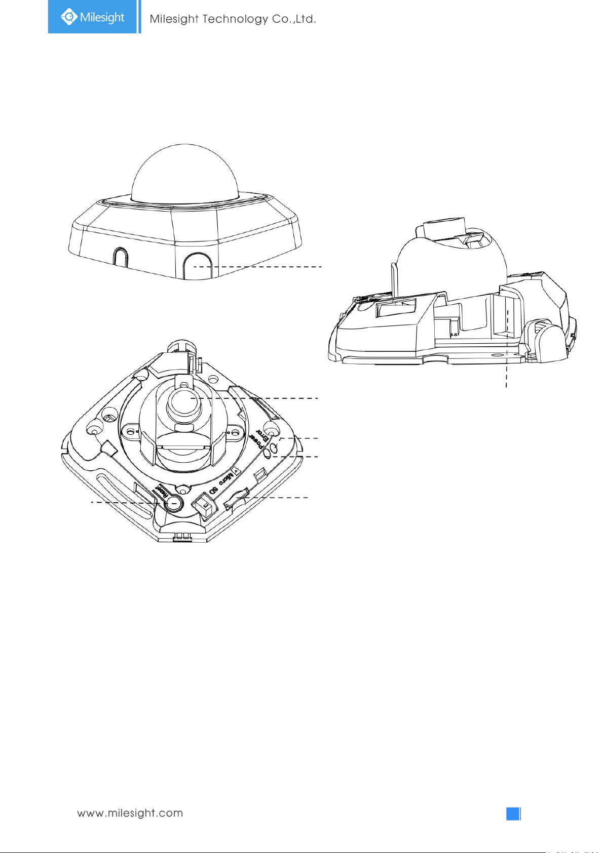
Press Button
Ethernet Port (PoE)
Lens
Error LED Indicator
Power LED Indicator
microSD/SDHC/SDXC Card Slot
Reset
1. Mini Dome Network Camera
Note:
1) Error LED Indicator: Error LED Indicator is on when the device starts up or runs error.
2) Reset Button: Press “Reset” button for 5 seconds, then the device will be restored to factory
default.
3) Only PoE is available for power supply.
Figure 1-3-1 Mini Dome Network Camera
Page 8
3
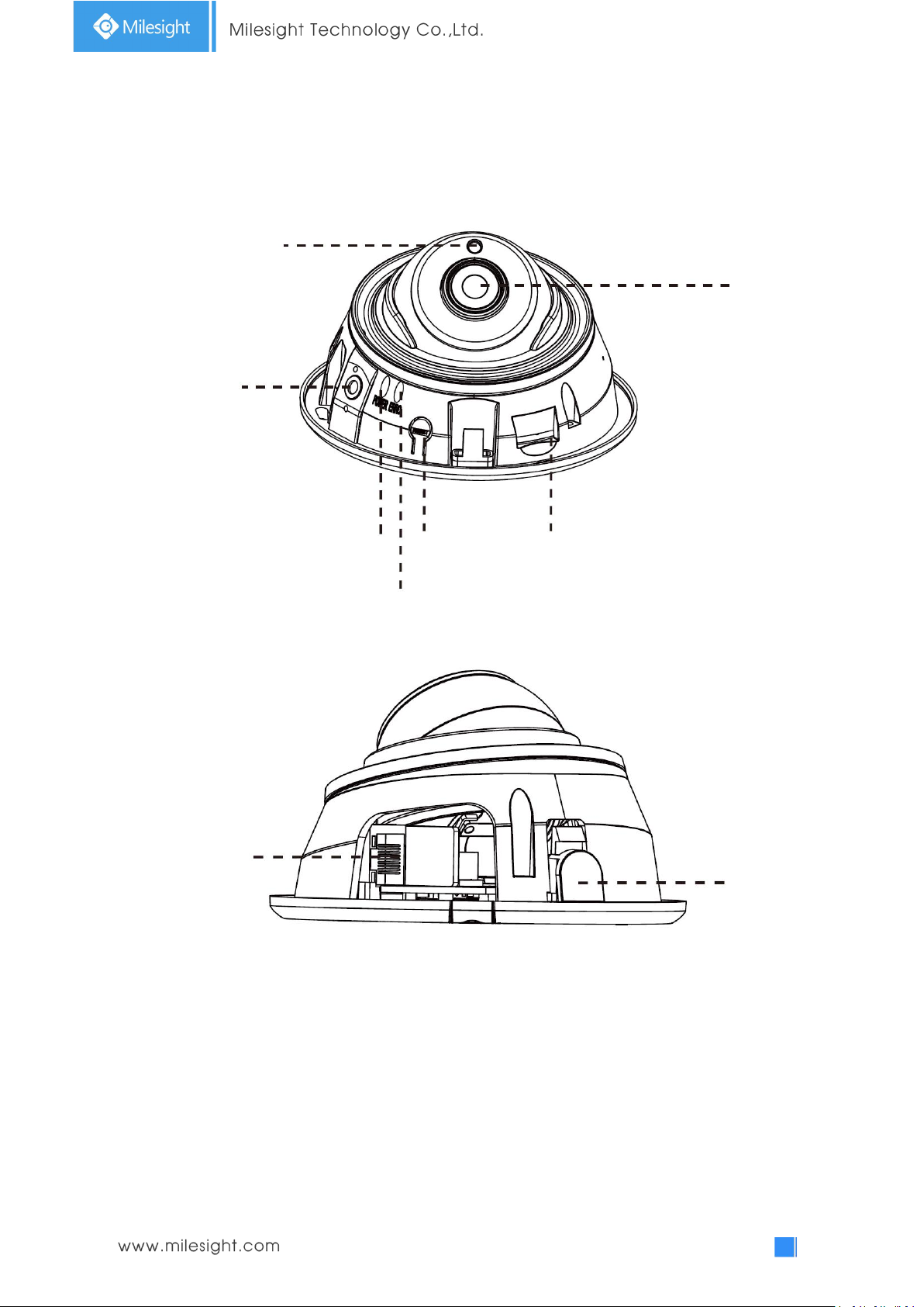
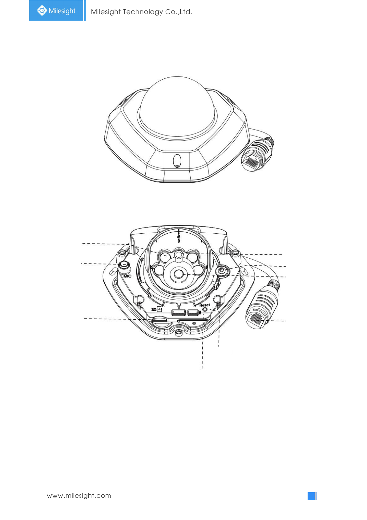
2. IR Mini Dome Network Camera
Ethernet Port (PoE)
Press Button
Light Sensor
Lens
Power LED Indicator
Error LED Indicator
Reset
microSD/SDHC/SDXC Card Slot
Microphone
Note:
1) Error LED Indicator: Error LED Indicator is on when the device starts up or runs error.
2) Reset Button: Press “Reset” button for 5 seconds, then the device will be restored to factory
default.
3) Only PoE is available for power supply.
Figure 1-3-2 IR Mini Dome Network Camera
Page 9
4
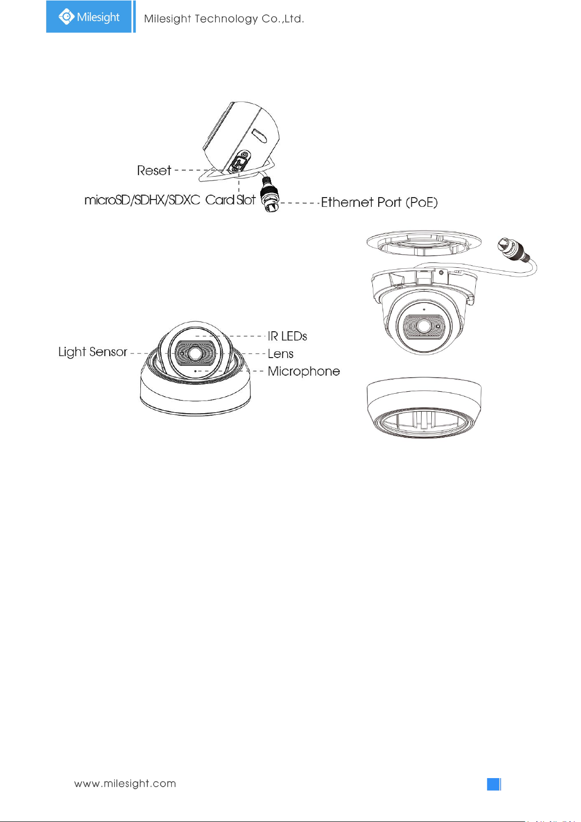
3. Vandal-proof Mini Dome Network Camera
IR LEDs
Light Sensor
Lens
Ethernet Port (PoE)
microSD/SDHC/SDXC
Card Slot
Microphone
Screw
Power and System LED Indicator
Reset
Note:
1) Error LED Indicator: Error LED Indicator is on when the device starts up or runs error.
2) Reset Button: Press “Reset” button for 5 seconds, then the device will be restored to factory
default.
3) Only PoE is available for power supply.
Figure 1-3-3 Vandal-proof Mini Dome Network Camera
Page 10
5
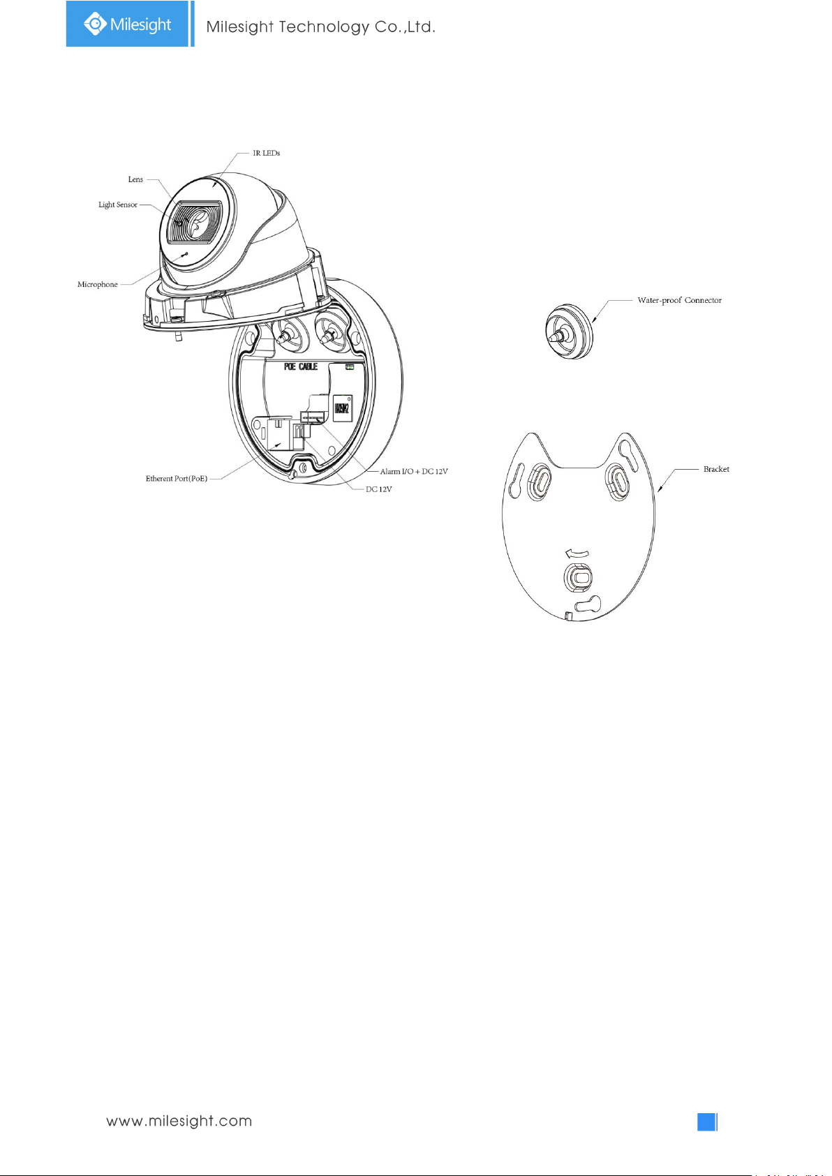
4. Weather-proof Mini Dome Network Camera
Figure 1-3-4 Weather-proof Mini Dome Network Camera
Note:
1) Reset Button: Press “Reset” button for 5 seconds, then the device will be restored to factory
default.
2) Only PoE is available for power supply.
Page 11
6
5. AF Motorized Mini Dome Network Camera
Figure 1-3-5 AF Motorized Mini Dome Network Camera
Note:
1) Reset Button: Press “Reset” button for 5 seconds, then the device will be restored to factory
default.
2) DC 12V and PoE are available for power supply.
Page 12
7
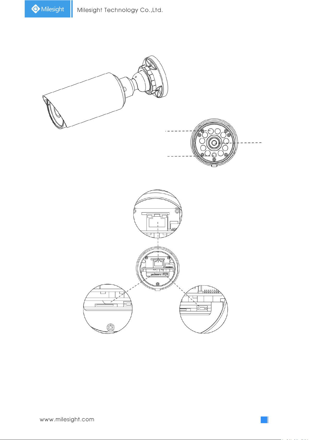
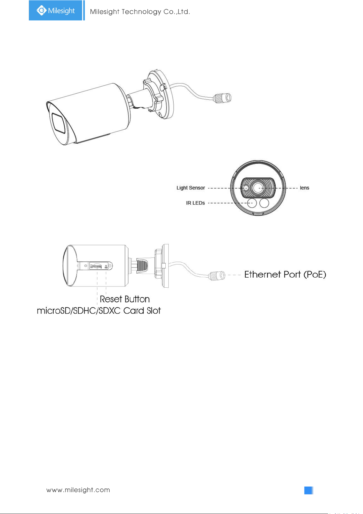
6. Mini Bullet Network Camera
Lens
IR LEDs
Light Sensor
Ethernet Port (PoE)
microSD/SDHC/SDXC Card Slot
Reset Button
Note:
1) Only PoE is available for power supply.
2) Reset Button: Press “Reset” button for 5 seconds, then the device will be restored to factory
default.
Figure 1-3-6 Mini Bullet Network Camera
Page 13
8
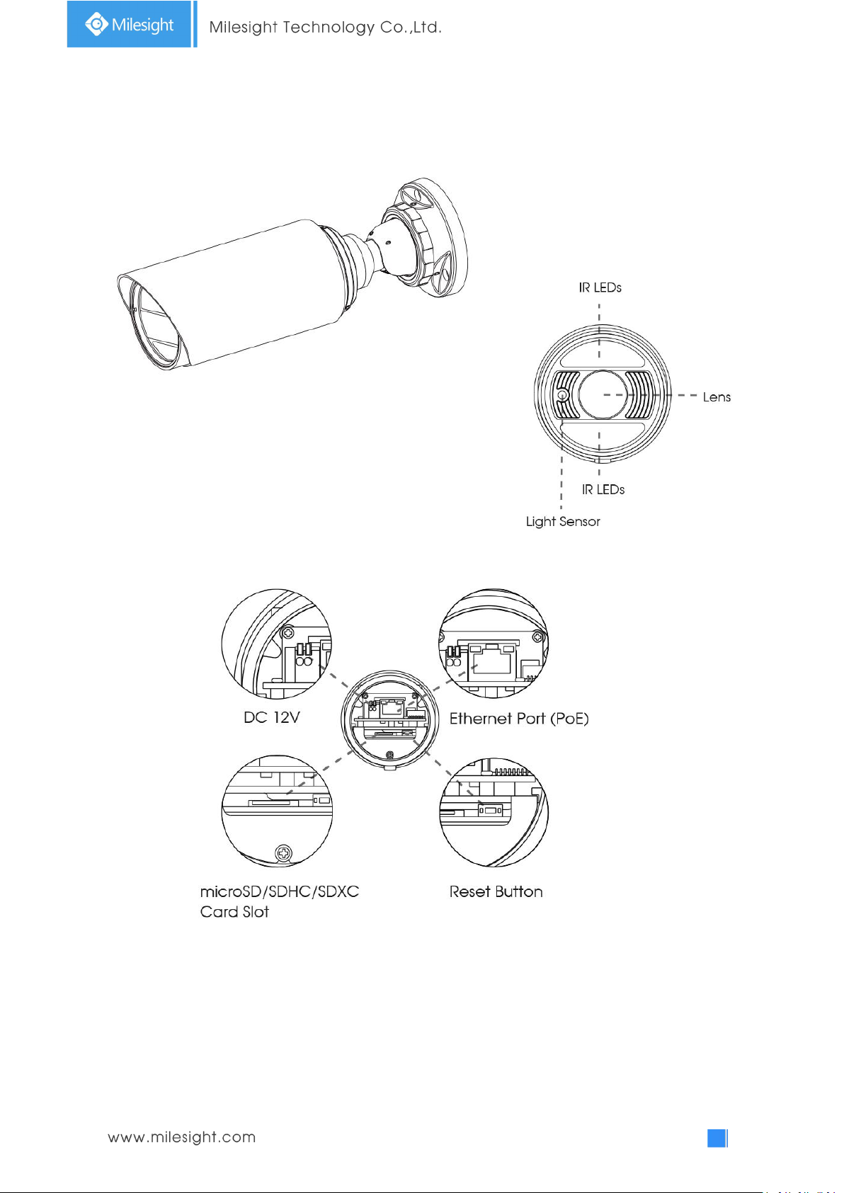
7. Vandal-proof Mini Bullet Network Camera
Figure 1-3-7 Vandal-proof Mini Bullet Network Camera
Note:
1) Only PoE is available for power supply.
2) Reset Button: Press “Reset” button for 5 seconds, then the device will be restored to factory
default.
Page 14
9
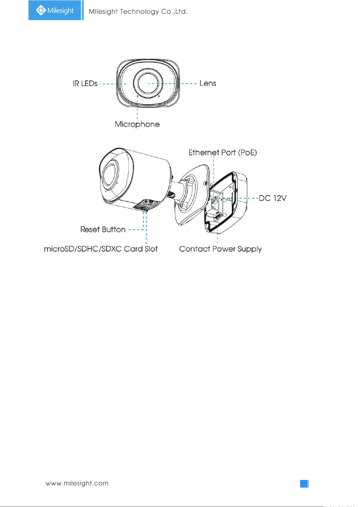
8. (Vandal-proof) Motorized Mini Bullet Network Camera
Ethernet Port (PoE)
Note:
1) DC 12V and PoE are available for power supply.
2) Reset Button: Press “Reset” button for 5 seconds, then the device will be restored to factory
Figure 1-3-8 (Vandal-proof) Motorized Mini Bullet Network Camera
default.
Page 15
10
9. 180°Panoramic Mini Bullet Network Camera
Note:
1) PoE is available for power supply.
2) Reset Button: Press “Reset” button for 5 seconds, then the device will be restored to factory
default.
Page 16
11
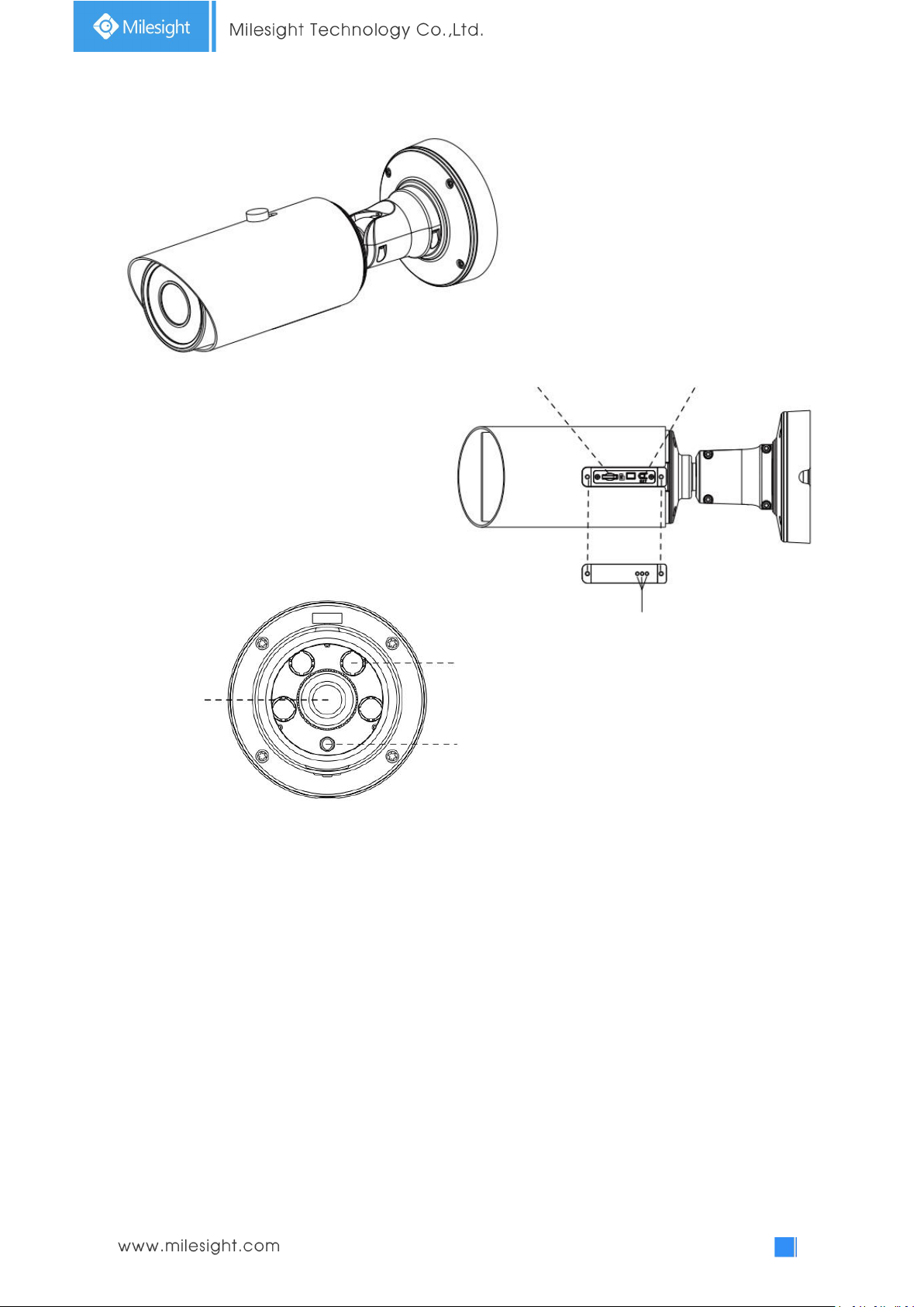
10. (12x AF) Motorized Pro Bullet Network Camera
microSD/SDHC/SDXC Card Slot
Reset
PTFE Membrane
IR LEDs
Lens
Light Sensor
Note:
3) DC 12V and PoE are available for power supply.
4) Reset Button: Press “Reset” button for 5 seconds, then the device will be restored to factory
default.
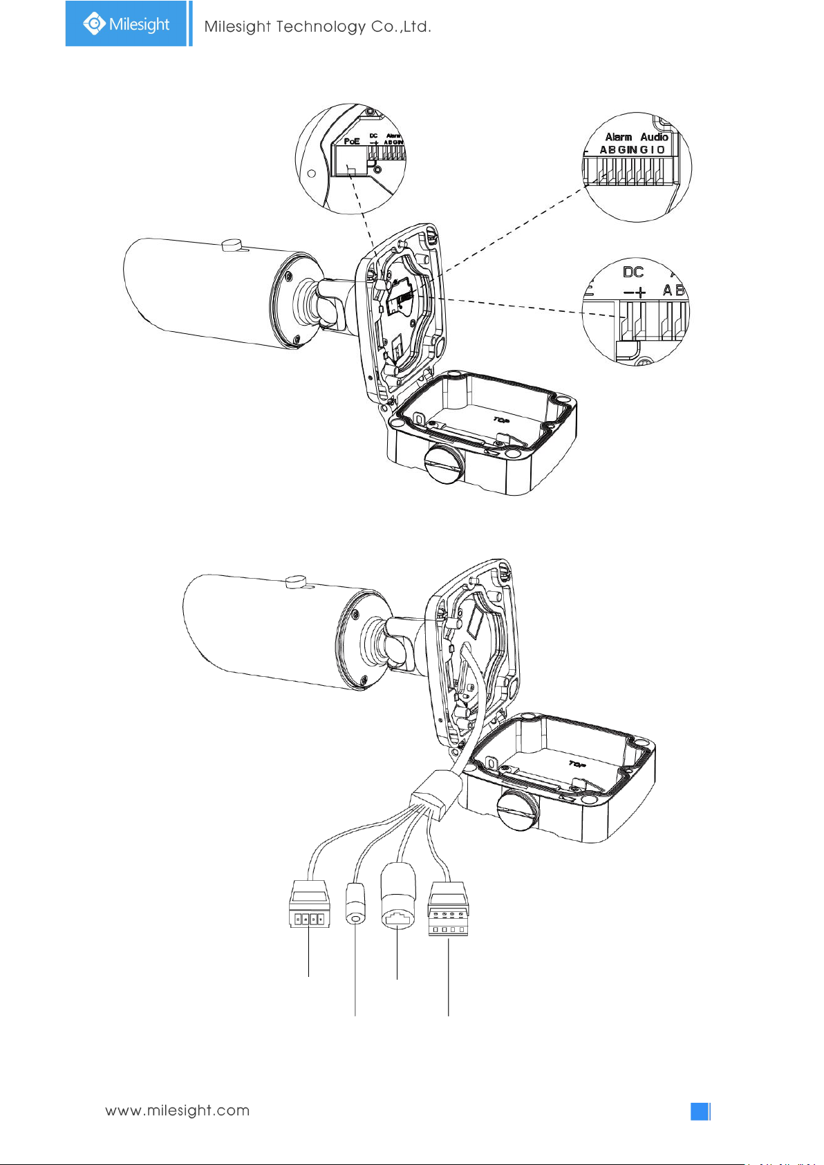
5) There are two versions for Pro Bullet: the interface’s pictures are as below.
Figure 1-3-9 (12x AF) Motorized Pro Bullet Network Camera
Page 17
12
Figure 1-3-10 Motorized Pro Bullet Network Camera(Version A)
Ethernet Port (PoE)
DC 12V
DC 12V
Alarm/Audio
Ethernet Port
(PoE)
Alarm In/Out
Audio In/Out
Figure 1-3-11 Motorized Pro Bullet Network Camera(Version B)
Page 18
13
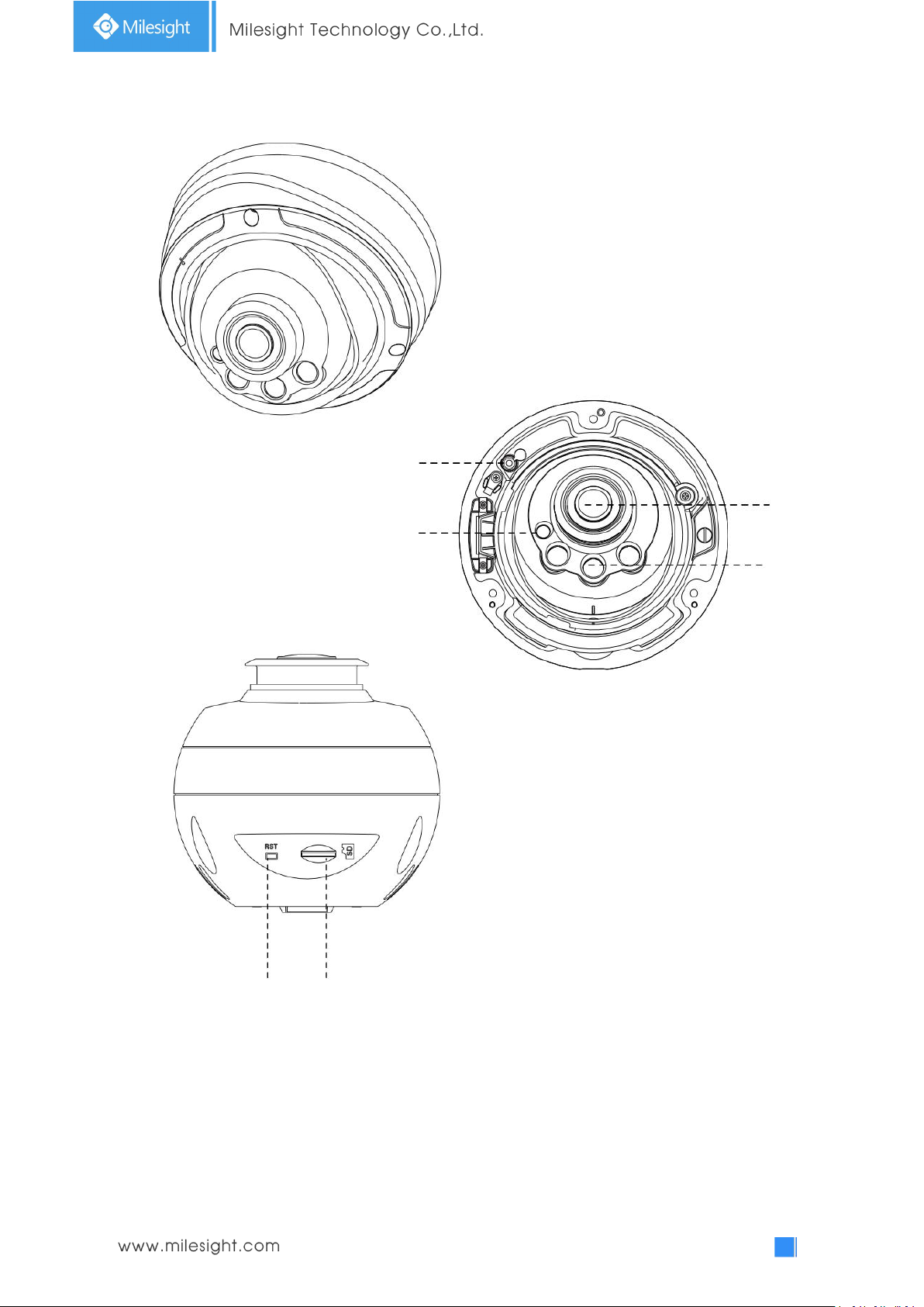
Microphone
Lens
IR LEDs
Light Sensor
Reset
11. Motorized Pro Dome Network Camera
microSD/SDHC/SDXC Card Slot
Note:
1) Reset Button: Press “Reset” button for 5 seconds, then the device will be restored to factory
default.
Figure 1-3-12 Motorized Pro Dome Network Camera
Page 19
14
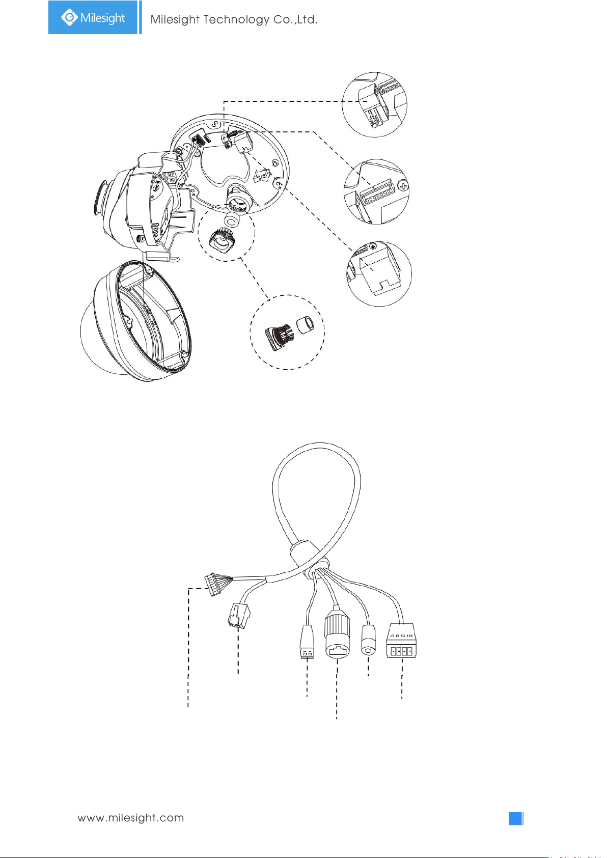
DC 12V
Alarm In/Out & Audio Out/DC 12V
Ethernet Port
(PoE)
Ethernet Port
(PoE)
Figure 1-3-13 Motorized Pro Dome Network Camera multiple interface
Ethernet Port (PoE)
Water-proof Connector
Alarm In/Out &
Audio Out/DC 12V
Audio Out
DC 12V
Alarm In/Out
Here is one equipped cable for multiple interface usage:
Figure 1-3-14 Motorized Pro Dome Network Camera multiple interface cable
Page 20
15
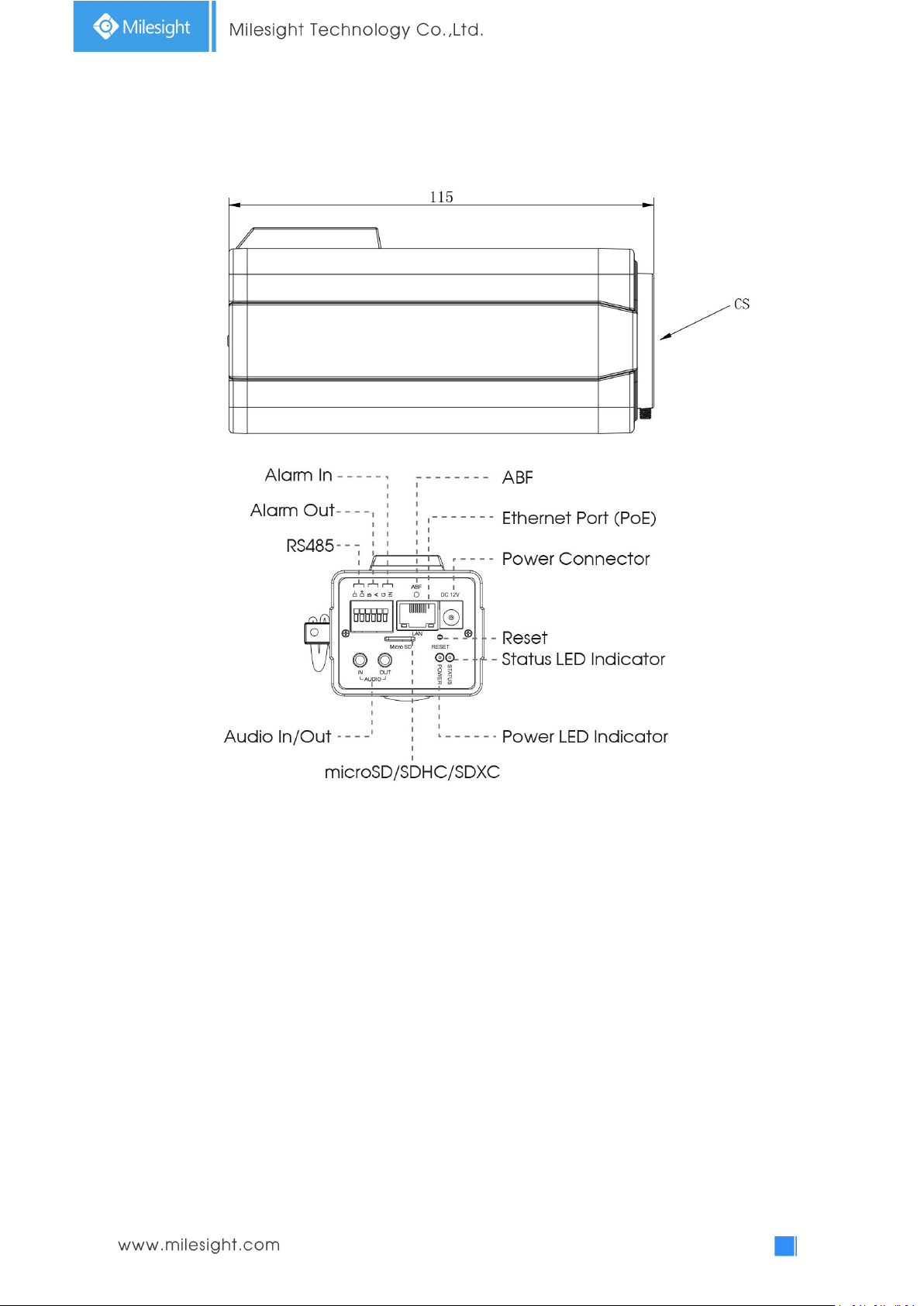
12. (LPR) (ABF) Pro Box Network Camera
Figure 1-3-15 (ABF) Pro Box Network Camera
Note:
1) Reset Button: Press “Reset” button for 5 seconds, then the device will be restored to factory
default.
2) DC 12V and PoE are available for power supply.
Page 21
16
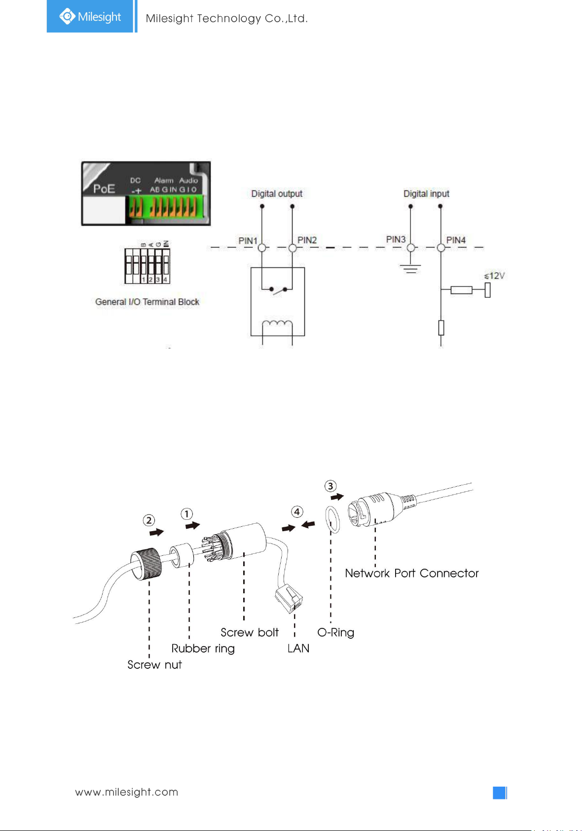
1.4 How to Connect to Alarm Interface
External interface of camera is as the following, you can refer to the picture to install the external
alarm device:
PIN1: Alarm Output NC/NO 24V DC 1A
PIN2: Alarm Output NC/NO 24V DC 1A
PIN3: Alarm Input NC/NO ≤12V
PIN4: Alarm Input NC/NO ≤12V
1.5 How to Connect the Water-proof Connector
Step1: Get the network cable through the screw nut, rubber ring and the screw bolt.
Step2: Insert the rubber ring into the screw bolt.
Step3: Connect the screw nut to the screw bolt.
Step4: Place the O-Ring on the network port connector.
Step5: Connect the RJ45 to the network port connector, and tighten the screw bolt and the
connector.
Page 22

17
1.6 System Requirements
Operating System: Windows XP/Vista/7/8/10/Server 2000/Server 2008
CPU: 1.66GHz or higher
RAM: 1G or higher
Graphic memory: 128MB or more
Internet protocol: TCP/IP (IPv4/IPv6)
Web Browsers: Internet Explorer 8.0 and above version, Mozilla Firefox, Google Chrome and Safari.
Page 23
18
Chapter II Network Connection
2.1 Setting the Camera over the LAN
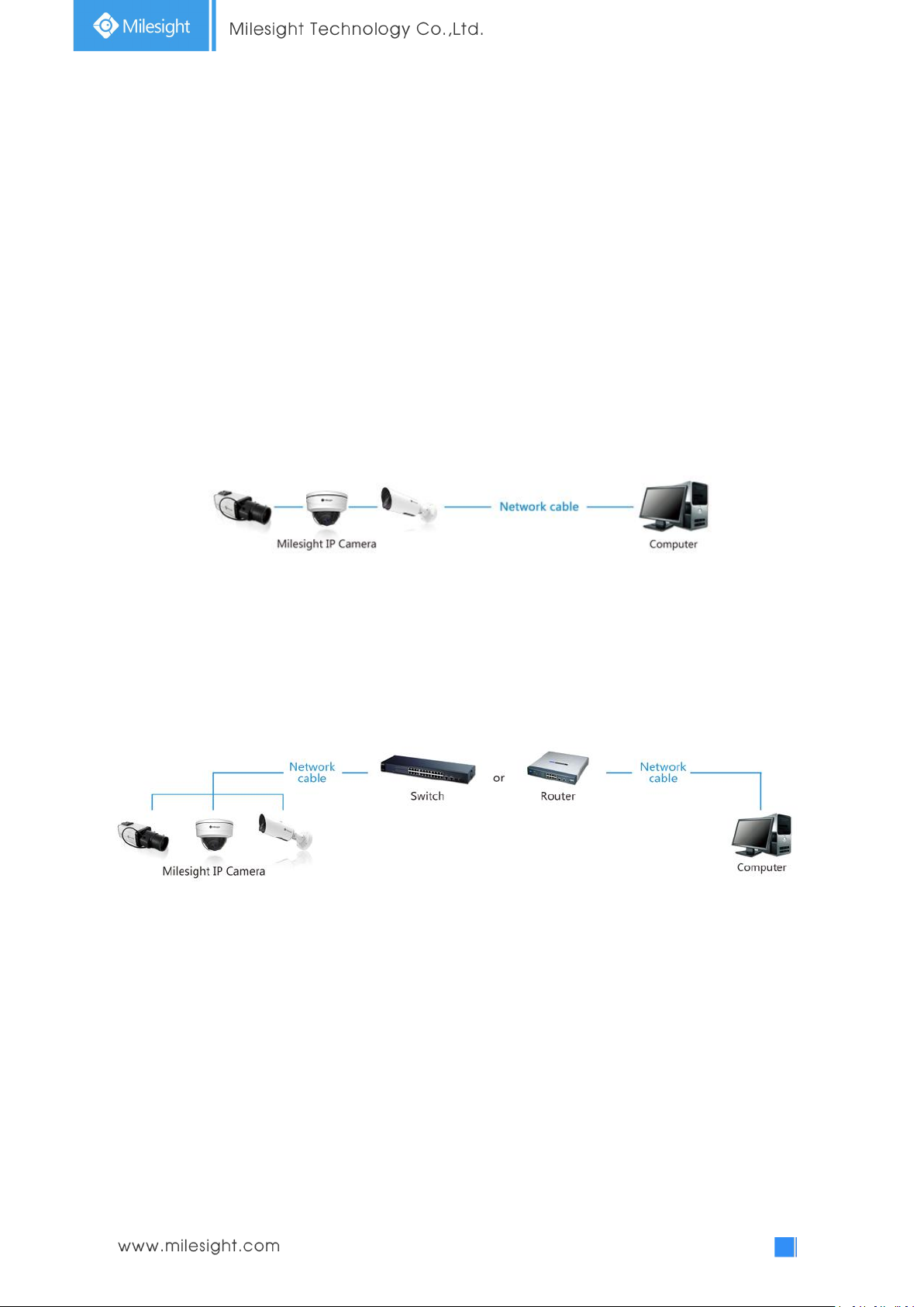
Connecting the camera to a switch or a router is the most common connection method. The
camera must be assigned an IP address that is compatible with its LAN.
2.1.1 Connect the Camera to the PC Directly
In this method, only the computer connected to the camera will be able to view the camera. The
camera must be assigned a compatible IP address to the computer. Details are shown as the
following figure.
Figure 2-1-1 Connect the camera to the PC directly
2.1.2 Connect via a Switch or a Router
Refer to the following figure to set network camera over the LAN via the switch or router.
Figure 2-1-2 Connect via a switch or a Router
2.2 Dynamic IP Connection
Connecting the network camera via a router
Step1: Connect the network camera to a router;
Step2: On the camera, assign a LAN IP address, the Subnet mask and the Gateway;
Step3: On the router, set port forwarding. E.g. 80, 8000 and 554 ports. The steps for port
forwarding vary depending on different routers. Please look up the router's user manual for
assistance with port forwarding;
Step4: Apply a domain name from a domain name provider;
Page 24

19
Step5: Configure the DDNS settings in the setting interface of the router;
Step6: Visit the camera via the domain name.
Figure 2-2 Connect the network camera via a router using dynamic IP
Page 25
20
Chapter III Accessing the Network Camera
The camera must be assigned an IP address to be accessible.
3.1 Assigning An IP Address
The Network Camera must be assigned an IP address to be accessible. The default IP address of
Milesight Network Camera is 192.168.5.190.
You can either change the IP address of the camera via Smart Tools or browser. Please connect the
camera in the same LAN of your computer.
3.1.1 Assigning An IP Address Using Smart Tools
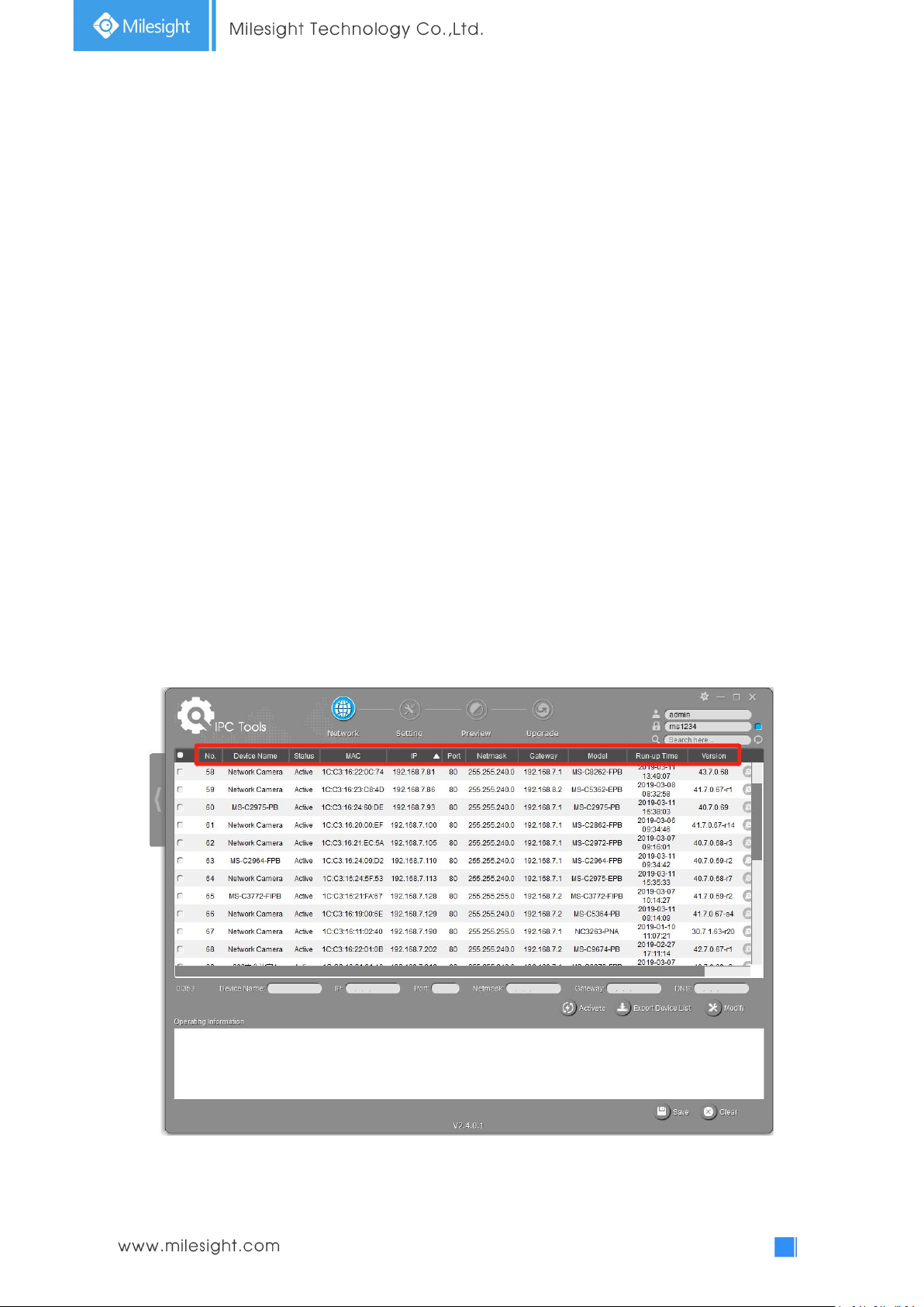
Smart Tools is a software tool which can automatically detect multiple online Milesight network
cameras in the LAN, set IP addresses, and manage firmware upgrades. It’s recommended to use
when assigning IP addresses for multiple cameras.
Step1: Install Smart Tools (The software could be downloaded from our website);
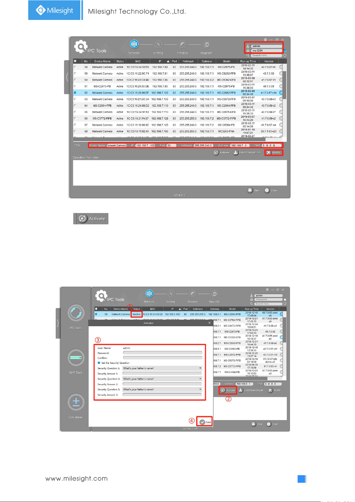
Step2: Start Smart Tools, click the IPC Tools page, then enter the device information, such as IP
address, MAC address, Status, Port number, Netmask, and Gateway, then all related
Milesight network cameras in the same network that will be displayed. Details are shown as
shown below;
Page 26
21
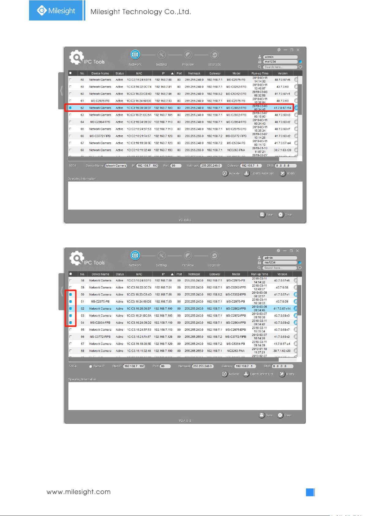
Step3: Select a camera or multiple cameras according to the MAC addresses;
Select single camera
Select multiple cameras
Step4: If the selected camera shows "Active" in the status bar, you can directly type the User Name
and Password (Camera with version lower than 4x.7.0.69 is using admin/ms1234 by default),
change the IP address or other network values, and then click “Modify” button;
Page 27
22
If the selected camera shows "Inactive" in the status bar(Camera with version V4x.7.0.69 or
above), click to set the password when using it for the first time. You can also set the
security questions when activating the camera in case that you forget the password(You can reset
the password by answering three security questions correctly). Click ‘Save’ and it will show that the
activation was successful.
Note:
(1) Password must be 8 to 32 characters long, contain at least one number and one letter.
(2) You need to upgrade Smart Tools version to V2.4.0.1 or above to activate the camera.
After activation, you can change the IP address or other network values, and then click “Modify”
button.
Page 28
23
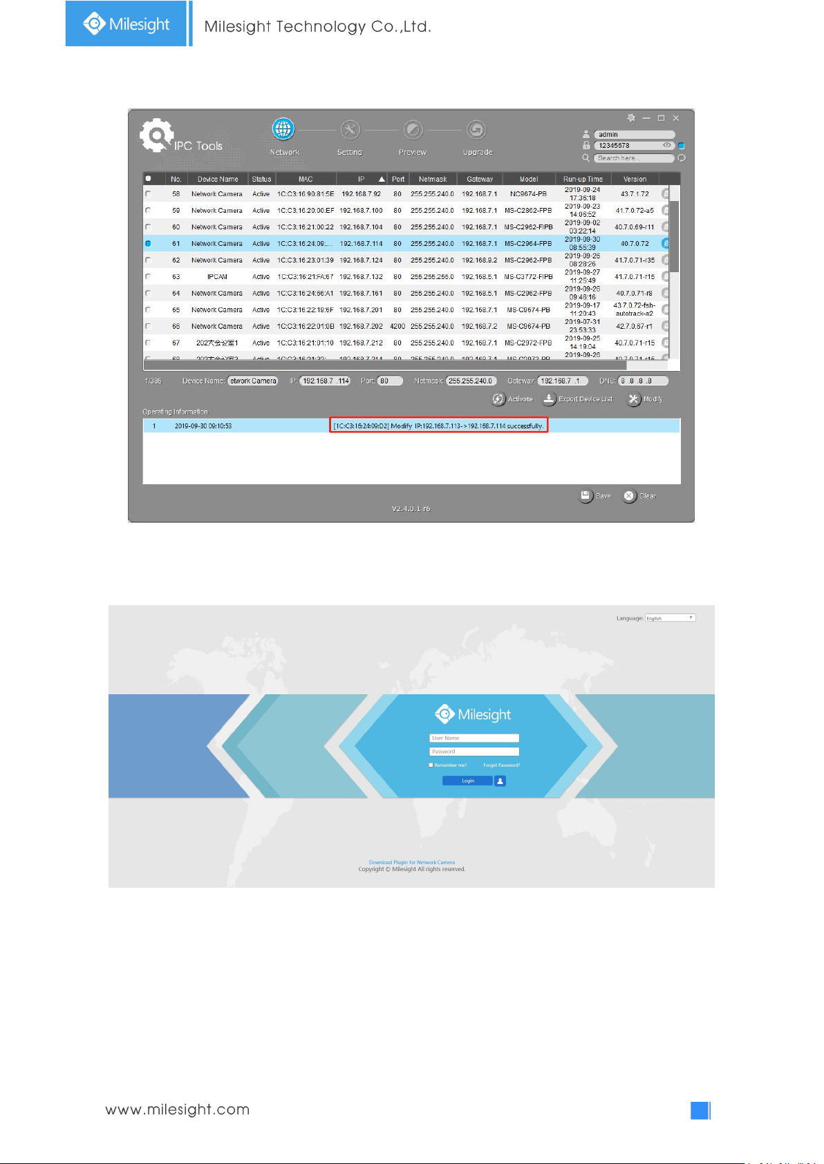
Step5: Change the IP address successfully;
Step6: By double clicking the selected camera or the browser of interested camera, you can access
the camera via web browser directly. The Internet Explorer window will pop up.
More usage of Smart Tools, please refer to the Smart Tools User Manual.
3.1.2 Assign An IP Address via Browser
If the network segment of the computer and that of the camera are different, please follow the
Page 29
24
steps to change the IP address:
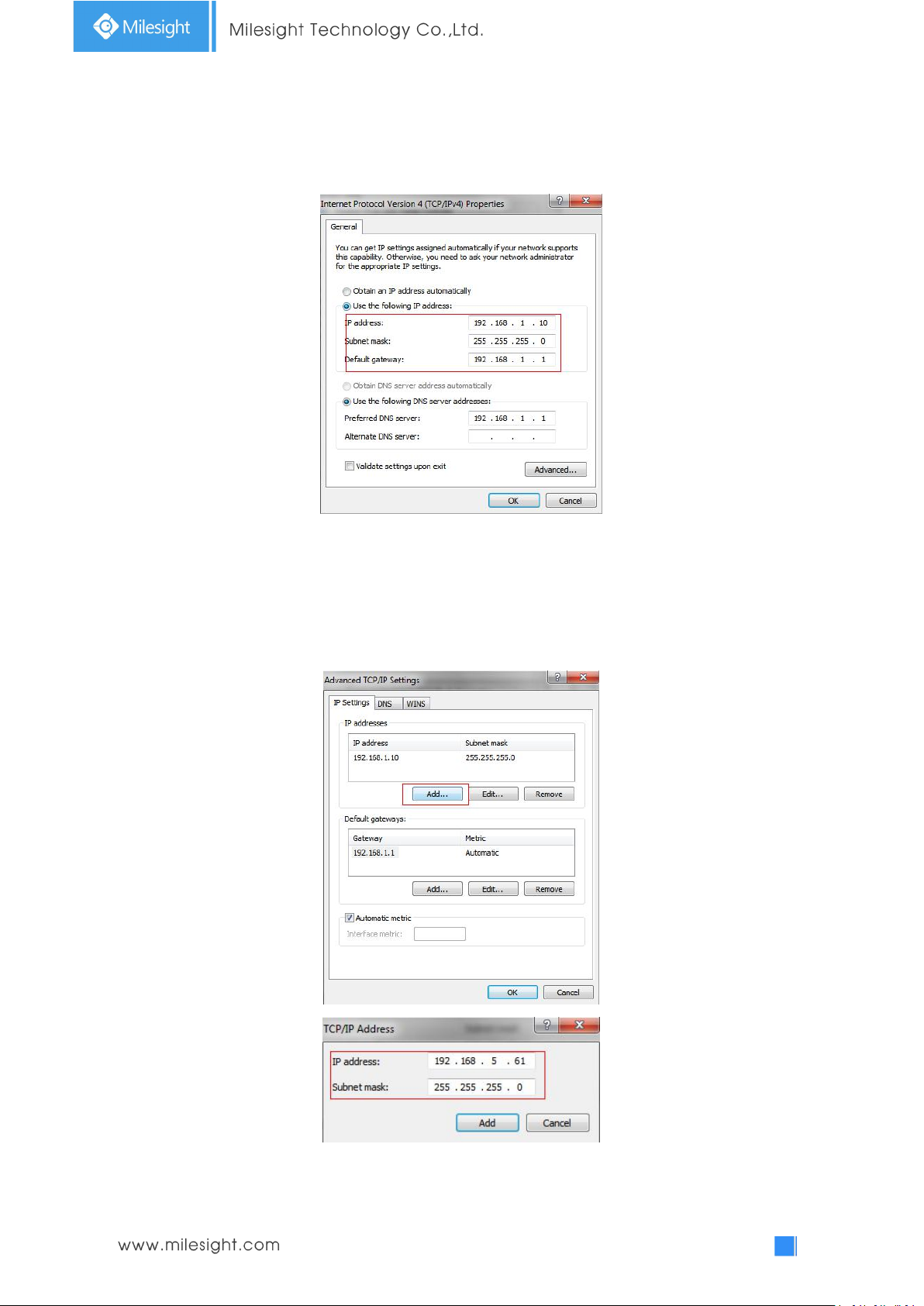
Step1: Change the IP address of computer to 192.168.5.0 segment, here are two ways as below:
a. StartControl PanelNetwork and Internet ConnectionNetwork Connection
Local Area Connection, and double click it. (Refer to Figure 3-1-8);
Figure 3-1-8 Setting Network Segment IP Address of Computer
b. Click “Advanced”, and then click “IP settings”“IP address”“Add” (See Figure
3-1-9). In the pop-up window, enter an IP address that in the same segment with
Milesight network camera ( e.g. 192.168.5.61, but please note that this IP address
shall not conflict with the IP address on the existing network);
Step2: Start the browser. In the address bar, enter the default IP address of the camera:
http://192.168.5.190;
Page 30
25
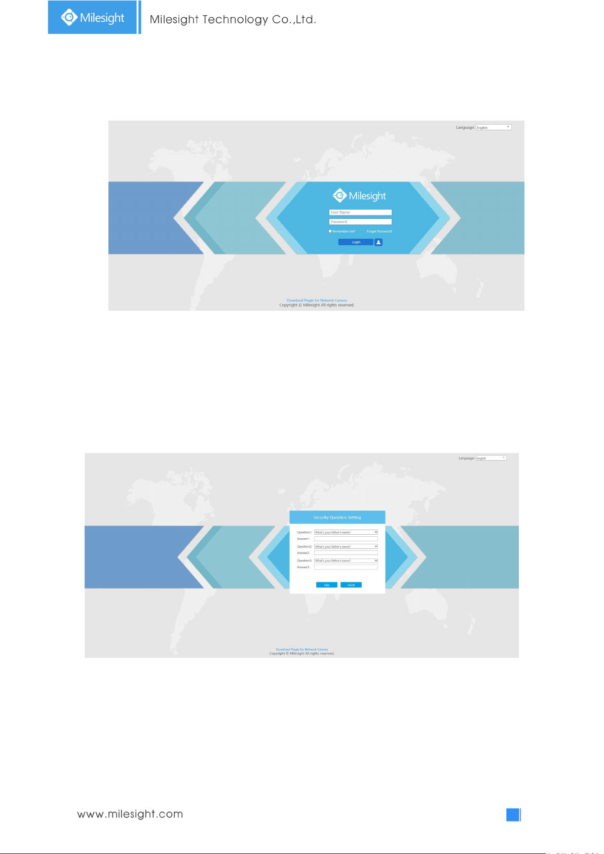
Step3: If the camera’s firmware version is lower than V4x.7.0.69, it will directly display the login
page, enter the user name and password when the LOGIN page appears;
Default user name: admin
Default password: ms1234
If the camera’s firmware version is V4x.7.0.69 or above, you need to set the password first
when using it for the first time. And you can also set three security questions for your device
after activation. Then, you can log in the device with You can log in to the camera with the
username(admin) and a custom password.
Note:
(1) Password must be 8 to 32 characters long, contain at least one number and one letter.
(2) You can click the “forget password” in login page to reset the password by answering three security
questions when you forget the password, if you set the security questions in advance.
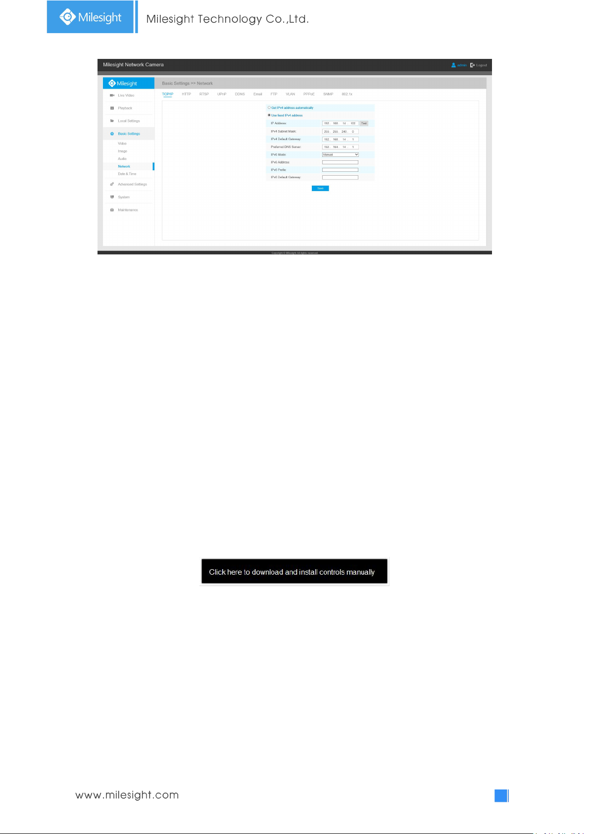
Step4: After login, please select “Configuration”“Basic Settings”“Network”“TCP/IP”. The
Network Settings page appears (Shown as below Figure);
Page 31
26
Step5: Change the IP address or other network values. Then click “Save” button;
Step6: The change of default IP address is completed.
3.2 Accessing from the Web Browser
The camera can be used with the most standard operating systems and browsers. The
recommended browsers are Internet Explorer, Firefox, Chrome, Microsoft Edge, Safari.
3.2.1 Access with Plugin
Currently you can only access the camera with plugin via Internet Explorer.
Access over IE Browser
Before using the browser to get access to your camera, you need to install the MsActiveX firstly.
You can refer the steps as follows:
Step1: Launch the IE browser and enter the IP address of the camera;
Step2: Enter the User Name and Password and click “Login”;
Step3: At the first time to log in the device, the browser will prompt to install Controls, please click
“Click here to download and install controls manually” as shown below;
Note:During installing the controls, please keep the browsers close.
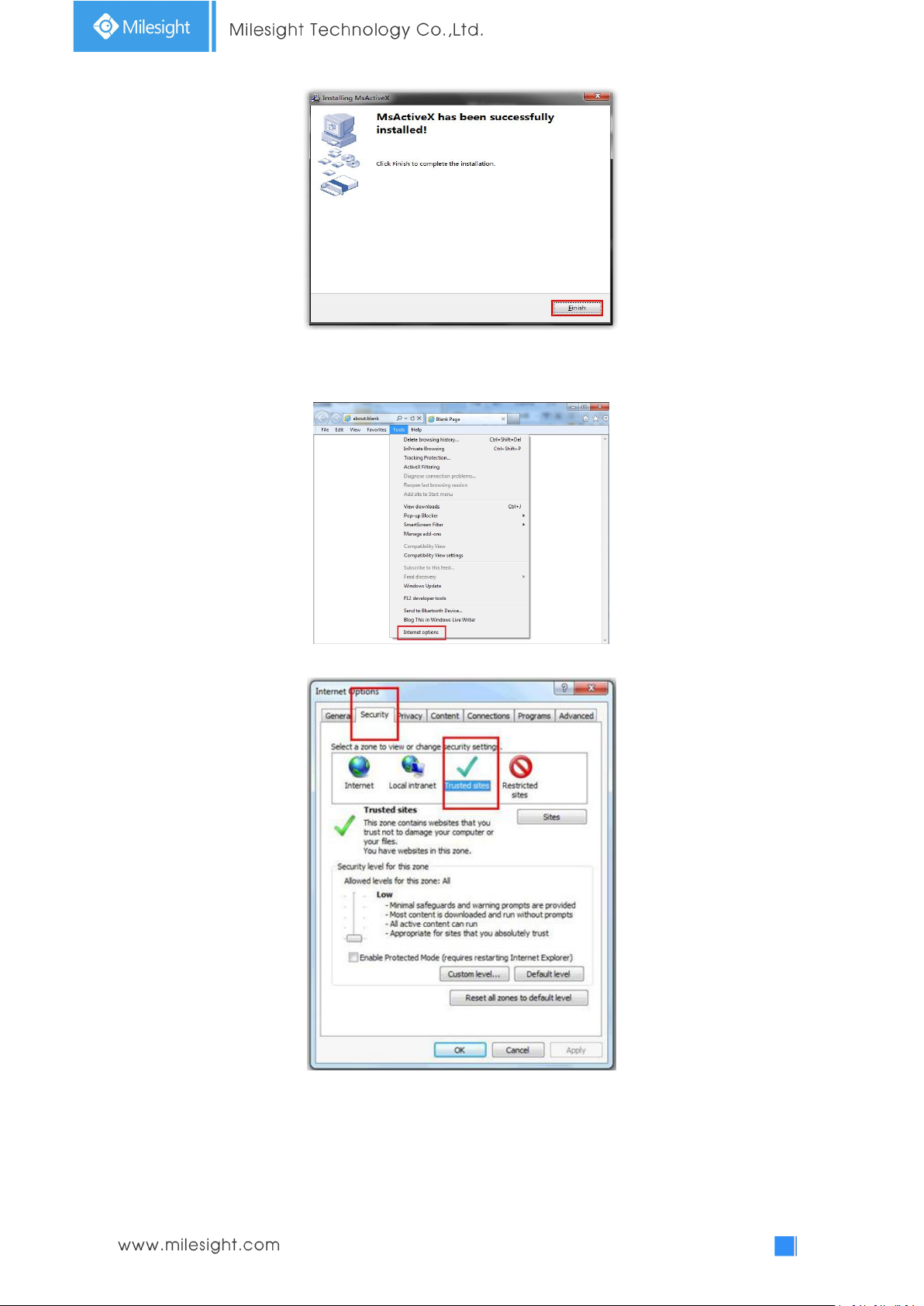
Step4: Follow the prompts to install the Controls, when it`s finished, it will pop out a window as
shown below. Please click “Finish” and refresh the browser, then you will see the video.
Page 32
27
If IE9 or higher version browser is used, it is suggested that the Milesight camera web link should
be added as a trusted site. See the instructions as follows:
Step1: Start the IE9 or higher version browser, and select “Tools”“Internet Options”;
Step2: Select “Security” to “Trusted”;
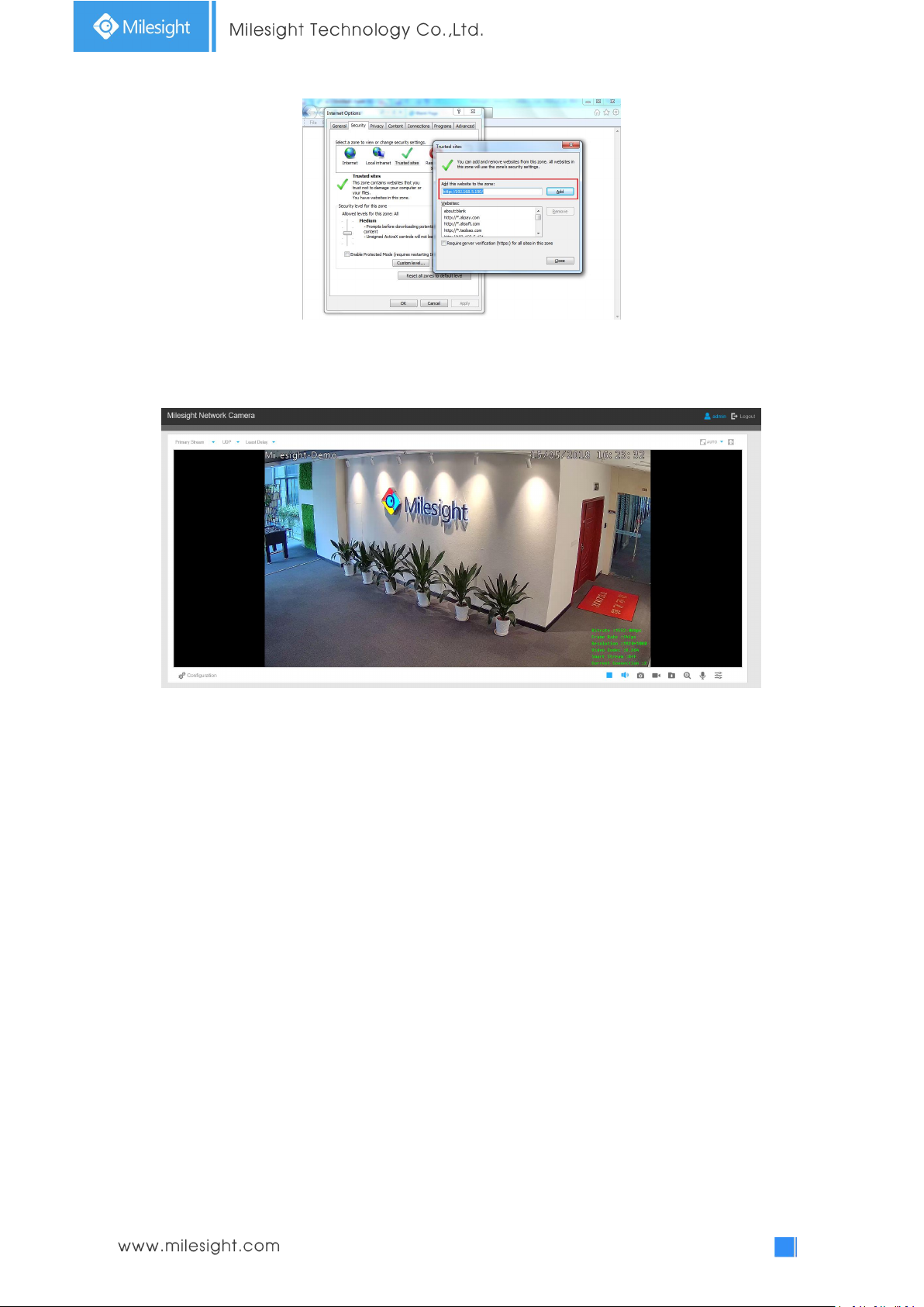
Step3: Enter the IP address of the camera in the blank and click “Add”;
Page 33
28
Step4: Enter the IP address. After logging on network camera’s web GUI successfully, user is
allowed to view live video as follows.
3.2.2 Access without Plugin
You can preview the video on the browser without plugin in Plugin-Free mode. Currently
Plugin-Free mode is supported in Chrome and Firefox browser for Windows system, MAC system
and Android system. Both H.265&H.264 video codec are supported in Plugin-Free Mode for
camera, and it will play the secondary stream by default.
Note:
① You need to upgrade camera to V4x.7.0.70 or above to use Plugin-Free Mode.
② If you use Chrome browser, Plugin-Free mode is only supported when the browser version is V69 or above.
③ If you use Firefox browser, Plugin-Free mode is only supported when the browser version is V65 or above.
(1) On Chrome browser
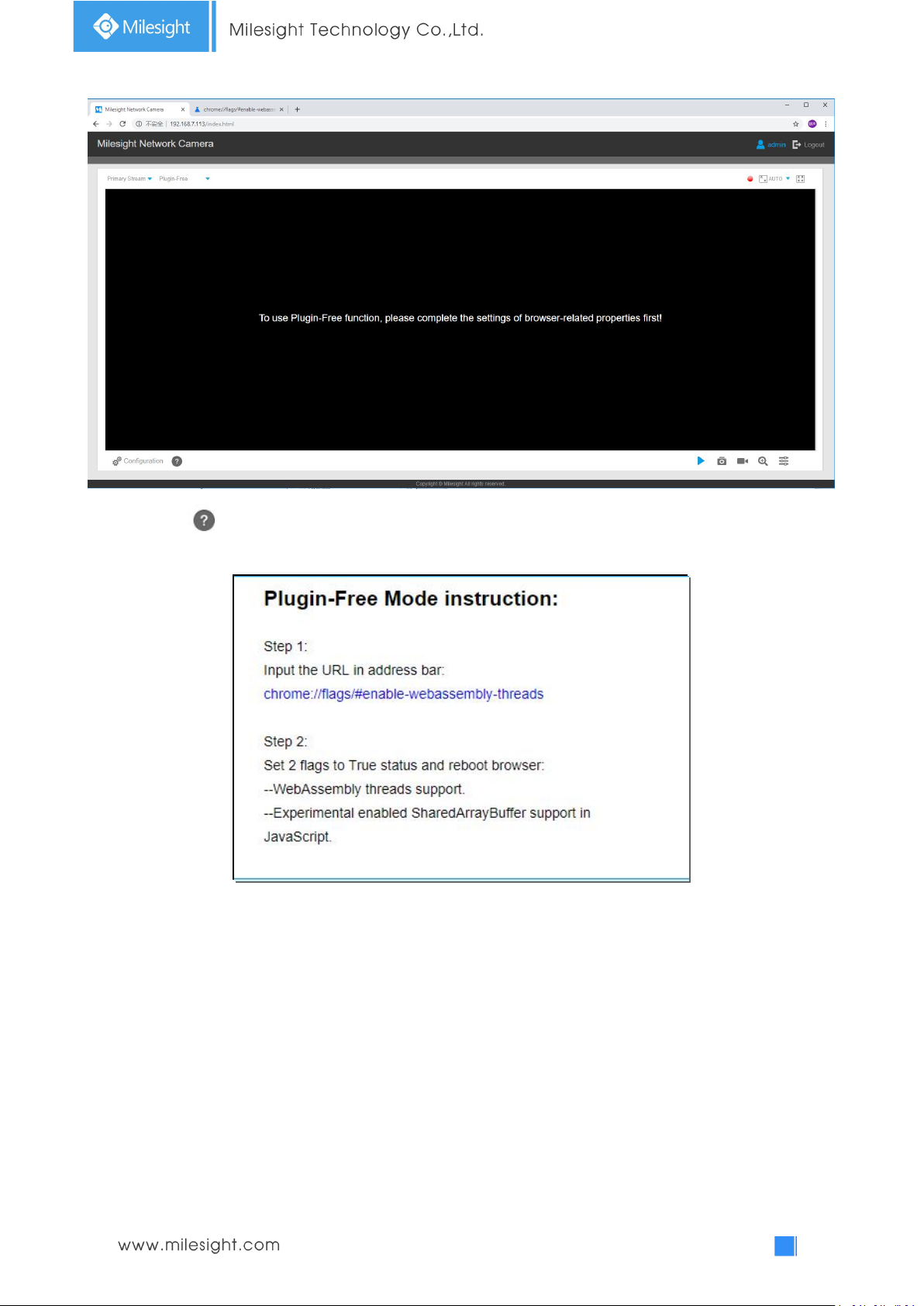
Step1: Access camera via Chrome browser.
Page 34
29
Step2: Click “ ” icon in the lower left corner of the webpage, you can refer to Plugin-Free Mode
instruction below.
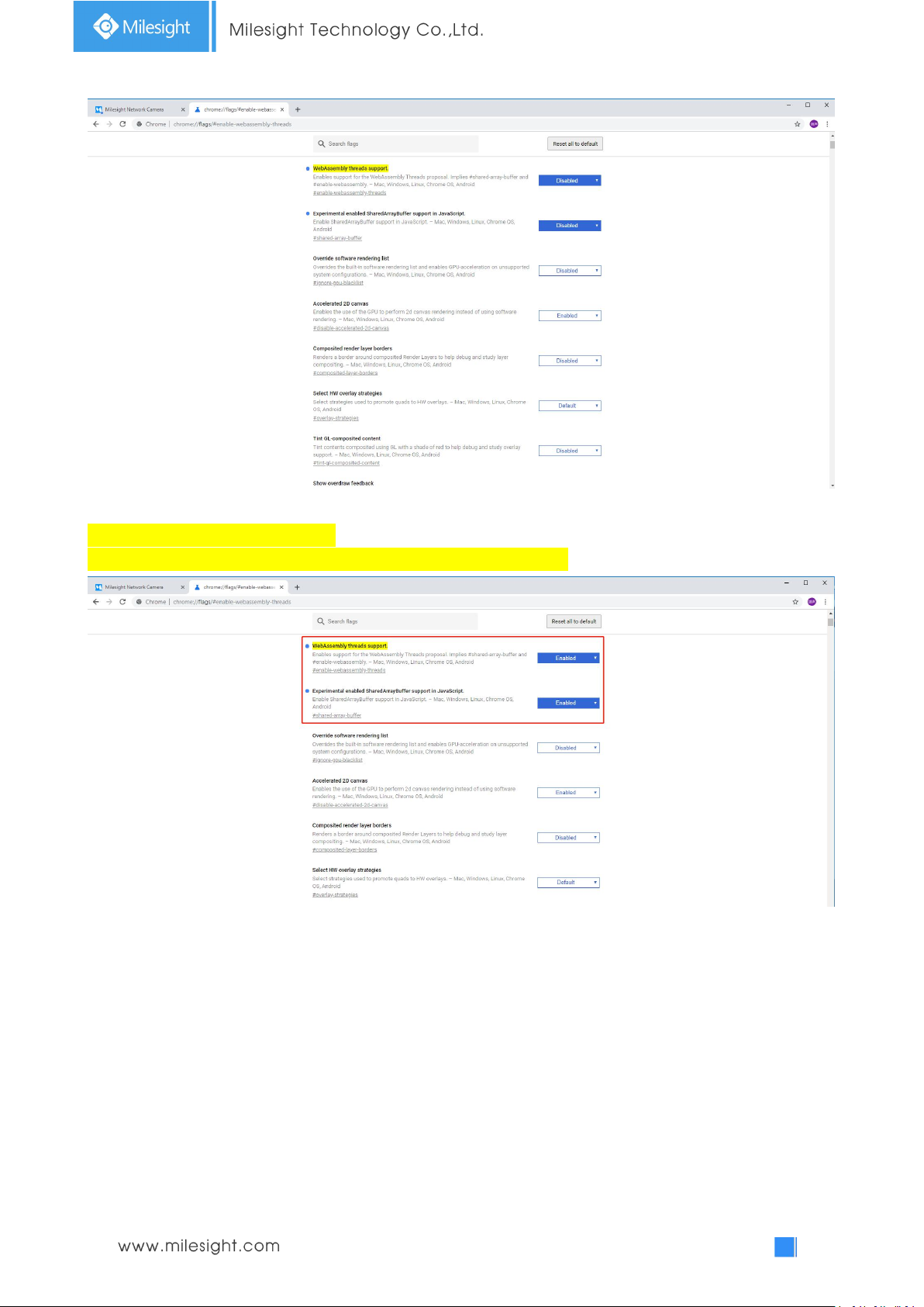
Step3: Input the URL in address bar: chrome://flags/#enable-webassembly-threads
You will enter the webpage shown below.
Page 35
30
Step4: Set 2 flags to True status and reboot browser:
--WebAssembly threads support.
--Experimental enabled SharedArrayBuffer support in JavaScript
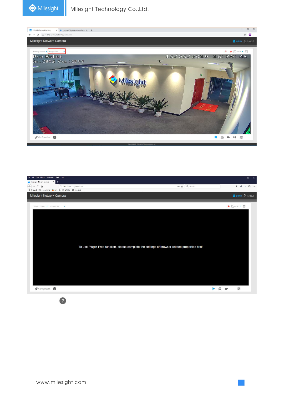
Step5: Then you can preview the video without plugin by selecting Plugin-Free mode in Live View
interface.
Page 36
31
It supports previewing the video in Live View and other setting interfaces.
(2) On Firefox browser
Step1: Access camera via Firefox browser.
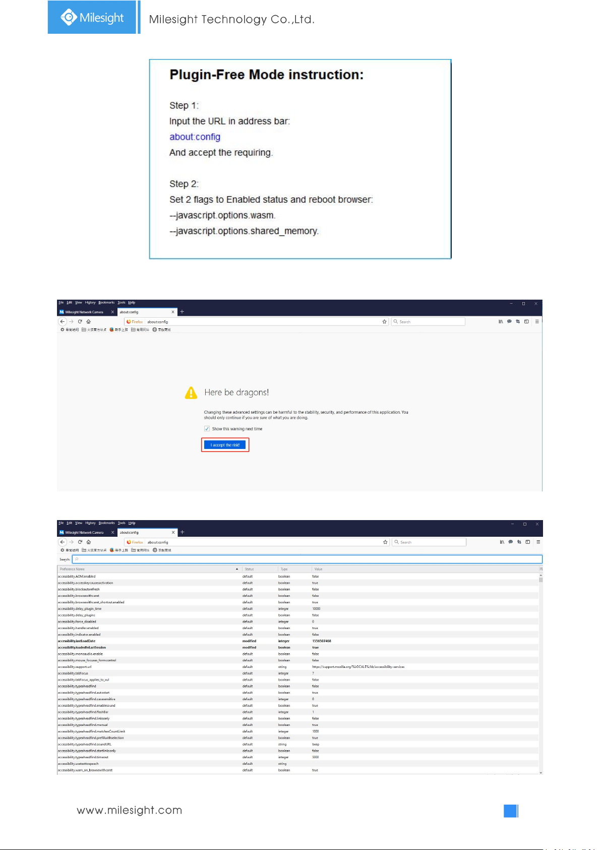
Step2: Click “ ” icon in the lower left corner of the webpage, you can refer to Plugin-Free Mode
instruction below.
Page 37
32
Step3: Input the URL in address bar: about:config
And accept the requiring.
You will enter the webpage shown below.
Page 38
33
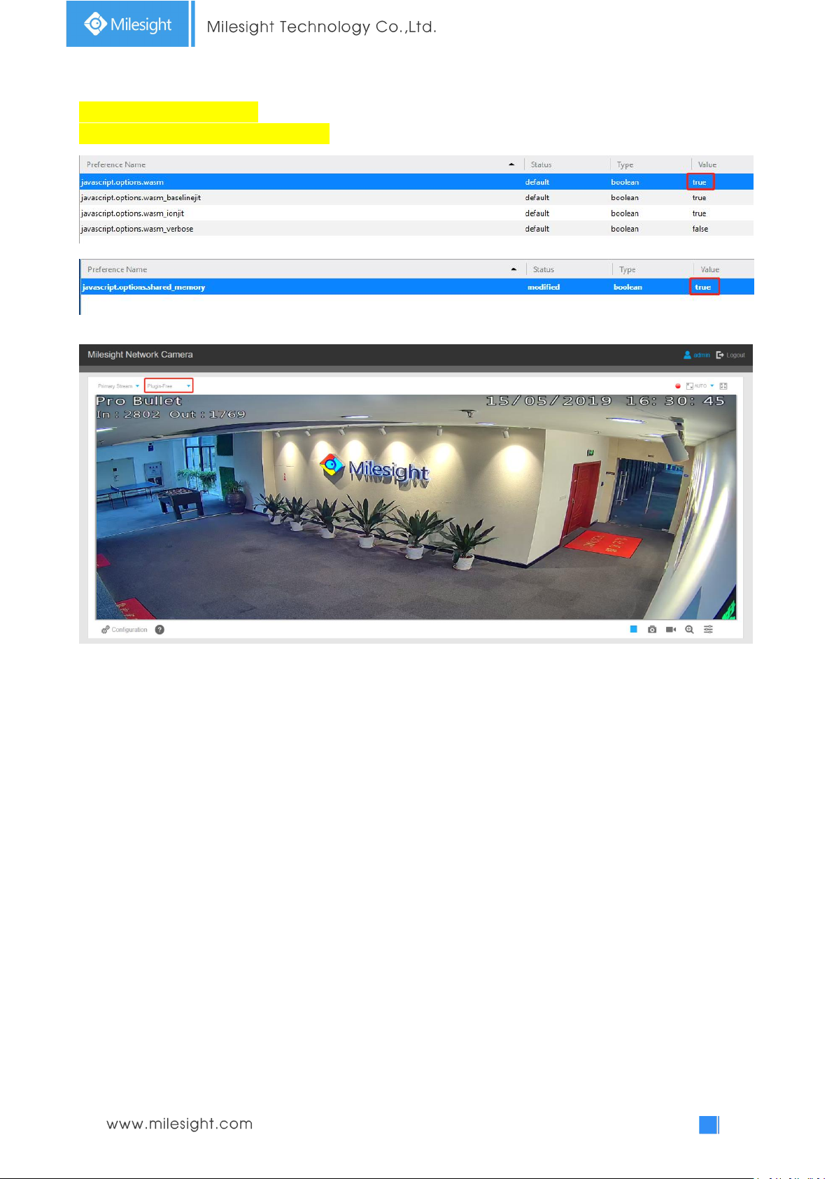
Step4: Set 2 flags to Enabled status and reboot browser:
--javascript.options.wasm.
--javascript.options.shared_memory.
Step5: Then you can preview the video without plugin by selecting Plugin-Free mode.
It supports previewing the video in Live View, Playback and other setting interfaces.
3.3 Accessing from Milesight VMS (Video Management Software)
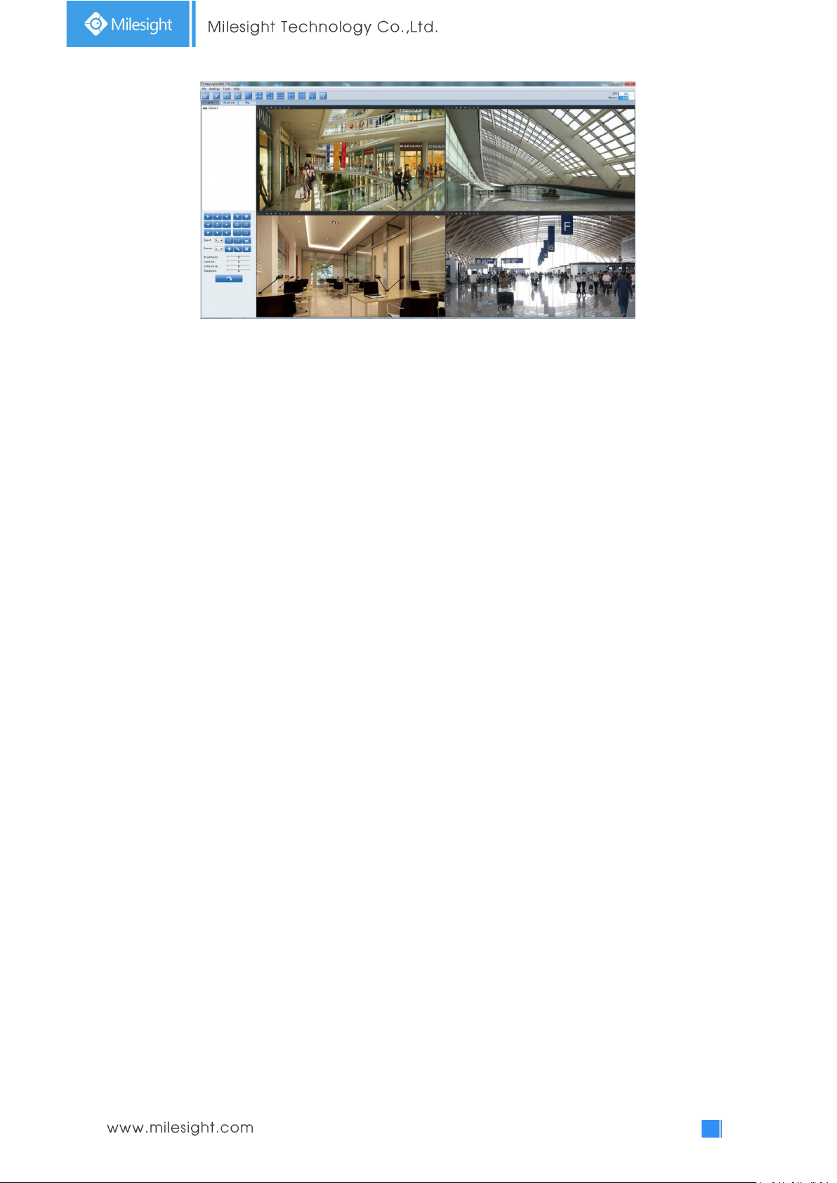
Milesight VMS(ONVIF compatible) is a handy and reliable application designed to work with
network cameras in order to provide video surveillance, recording settings and event management
functions. The interface of Milesight VMS is very easy to use, intuitive, with easy access to the
most common activities, such as viewing live video, searching through recordings and exporting
videos and snapshots. It's able to be integrated with other devices through ONVIF. It is designed to
work on Windows XP/ 7/ 8/ Vista/ Server 2000/ Server 2008. The software could be downloaded
from our website www.milesight.com.
Please install Milesight VMS; then launch the program to add the camera to the channel list. For
detailed information about how to use the software, please refer to user manual of Milesight VMS.
Page 39
34
Milesight VMS Live View
Page 40
35
Chapter IV System Operation Guide
No.
Parameter
Description
1
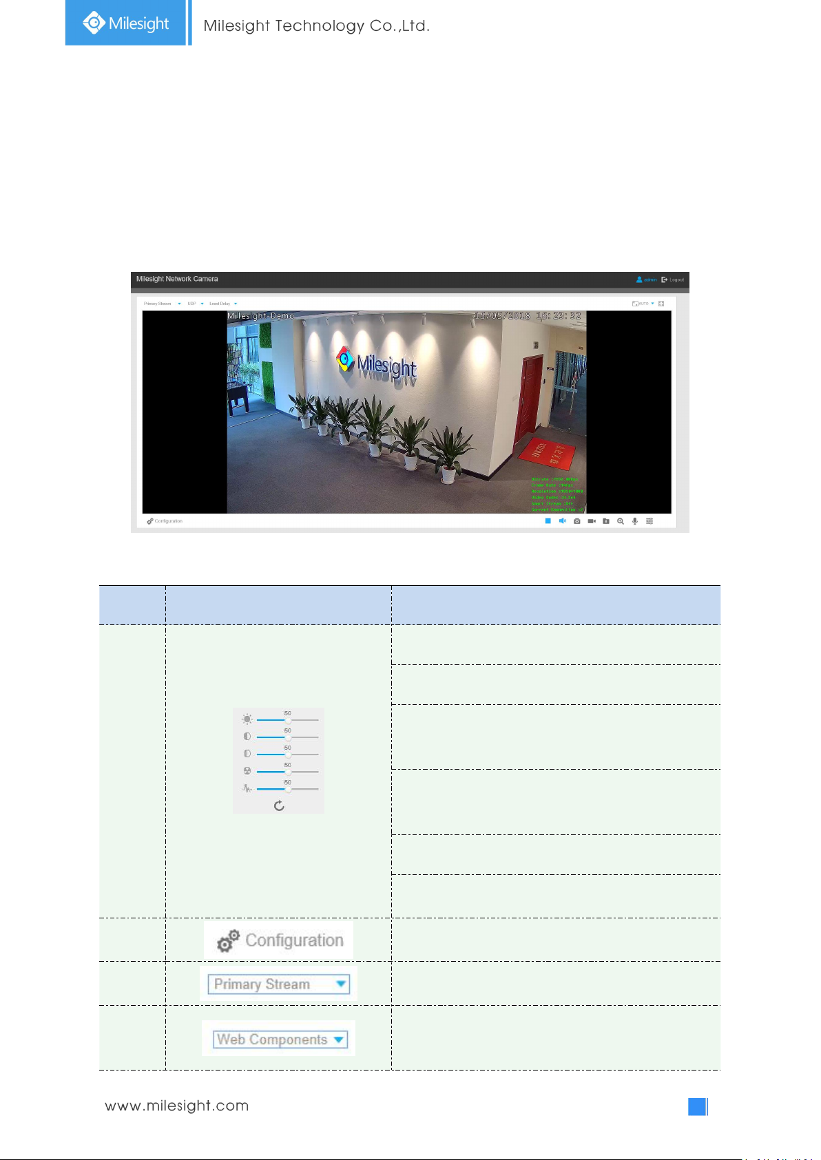
Image Adjustment
Brightness: Adjust the Brightness of the scene
Contrast: Adjust the color and light contrast
Saturation: Adjust the Saturation of the image.Higher
Saturation makes colors appear more "pure" while
lower one appears more “wash-out”
Sharpness: Adjust the Sharpness of image. Higher
Sharpness sharps the pixel boundary and makes the
image looks “more clear”
Noise Reduction Level: Adjust the noise reduction level
Default: Restore brightness, contrast and saturation to
default settings
Click to access the configuration page
2
Choose the Stream (Primary/Secondary/Tertiary)to
show on the current video window
3
Only available for camera whose software version is
43 or above
Web Components: Support Firefox, Safari, Chrome
4.1 Live Video
After logging in the network camera web GUI successfully, user is allowed to view live video as
follows.
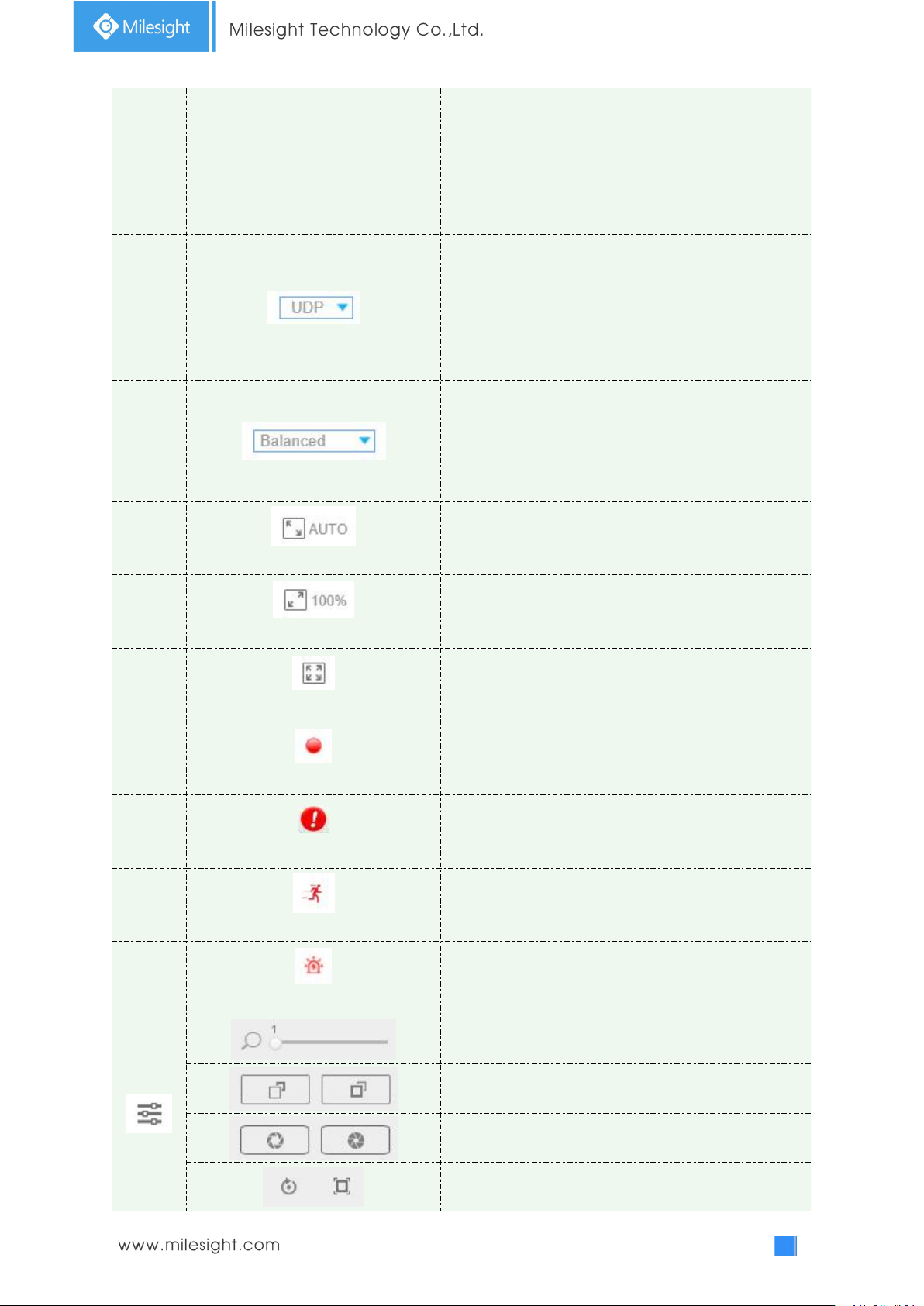
Table 4-1-1 Description of the buttons
Page 41
36
(Chrome version 44 or below); need to install the
component to display the view;
MJPEG: Support to display the view on Firefox, Safari,
Chrome (Chrome version 45 or above);
(NOTE: IE choose Web Components mode for default, in
this case, it will not show the options)
4
TCP: More reliable connection;
UDP: More instantaneous connection, but if you cannot
get the live view successfully, please turn into TCP
connection;
HTTP: Faster and safer connection especially in Internet
environment.
5
Least Delay: The most instantaneous mode;
Balanced: A balanced mode between Least Delay and
Best Fluency, maintains the fluency while keeps an
acceptable delay;
Best Fluency: The most fluent mode;
6
Window size
Click to display images at a window size
7
Real size
Click to display images at a real size
8
Full Screen
Click to display images at full-screen
9
Recording
When recording, the icon will turn red
10
Alarm
When an alarm of Smart Event was triggered, the icon
appears
11
Alarm
When an alarm of Motion Detection was triggered,
the icon appears
12
Alarm
Except for the two kinds of alarms above, when other
alarms were triggered, the icon appears
Adjust the Zoom length of the lens(Only work when
your camera is equipped with motorized lens
)
Adjust focus of the lens(Only work when your camera is
equipped with motorized lens)
Adjust the size of Iris(Only work when your camera is
equipped with P-Iris)
Auxiliary Focus and Lens Initialization(Only work when
your camera is equipped with motorized lens)
Page 42
37
Adjust iris automatically if check this box ( Only work
when your camera is equipped with P-Iris)
14
/
Start/Stop live view
15
Capture
Click to capture the current image and save to the
configured path. The default path is
C:VMS\+-1\ IMAGE-MANUAL
16
/
Start Recording
Click to start recording video and save to the configured
path. The default path is C:VMS\+-1\MS_Record. Click
again to stop recording
17
Play Audio
Enable Audio Input/Output. It can also be set in Audio
configuration page
18
Saving Path Settings
Set the saving path for captured images and video
recordings of operating on the live view
19
Enable Digital Zoom
When enabled, you can zoom in in a specific area of
video image with your mouse wheel
20
Start Talking
When it is enabled, you can start real-time talking.
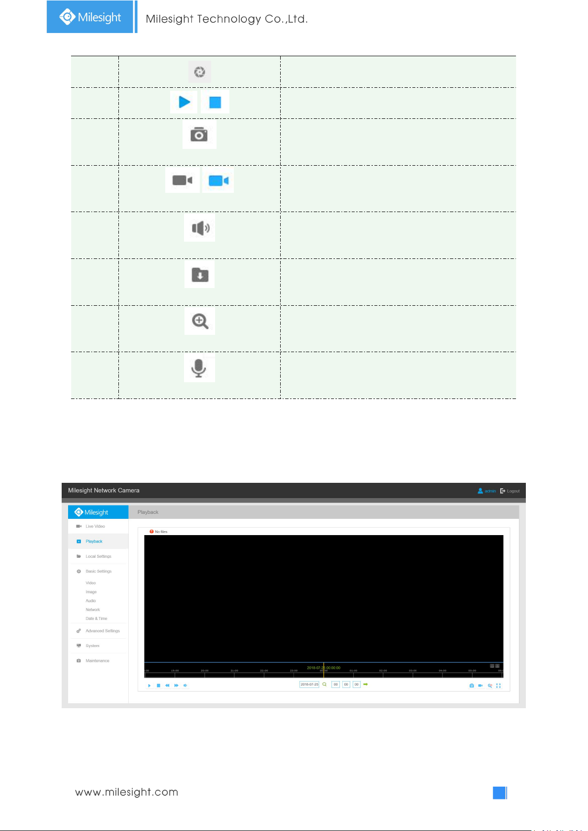
4.2 Playback
This section explains how to view the recorded video files stored in SD cards or NAS.
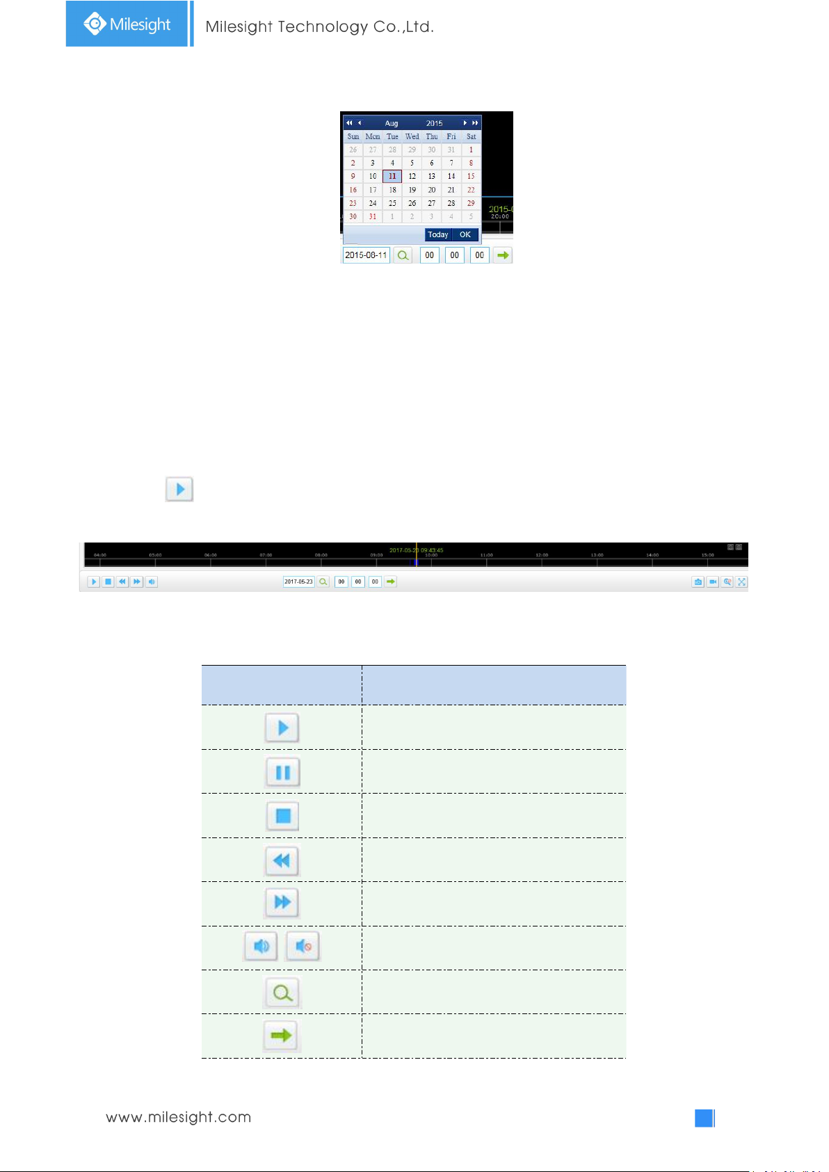
Step1: Click [Playback] on the menu bar to enter playback interface;
Page 43
38
Step2: Click the date button, choose the date when date window pops up;
Button
Operation
Play
Pause
Stop
Speed Down
Speed Up
/
Audio On/Off
Search
Go To
Note:
1) The date with bright red means current date; one with a dark red number and white
background means weekend day; one with a dark red number and blue background means
that the date is selected now.
2) It supports Plugin-free Playback function which allows to preview the playback without installi
ng plugin in Firefox (Version 65 and above) & Google Chrome (Version 69 and above) ;
You need to configure the browser properties before using this function. Please refer to 3.2.2
Access without Plugin for more browser configuration.
Step3: Click to play the video files found on this date.
The toolbar on the button of playback interface can be used to control playing progress.
Playback Toolbar
Table 4-2-1 Description of the buttons
Page 44
39
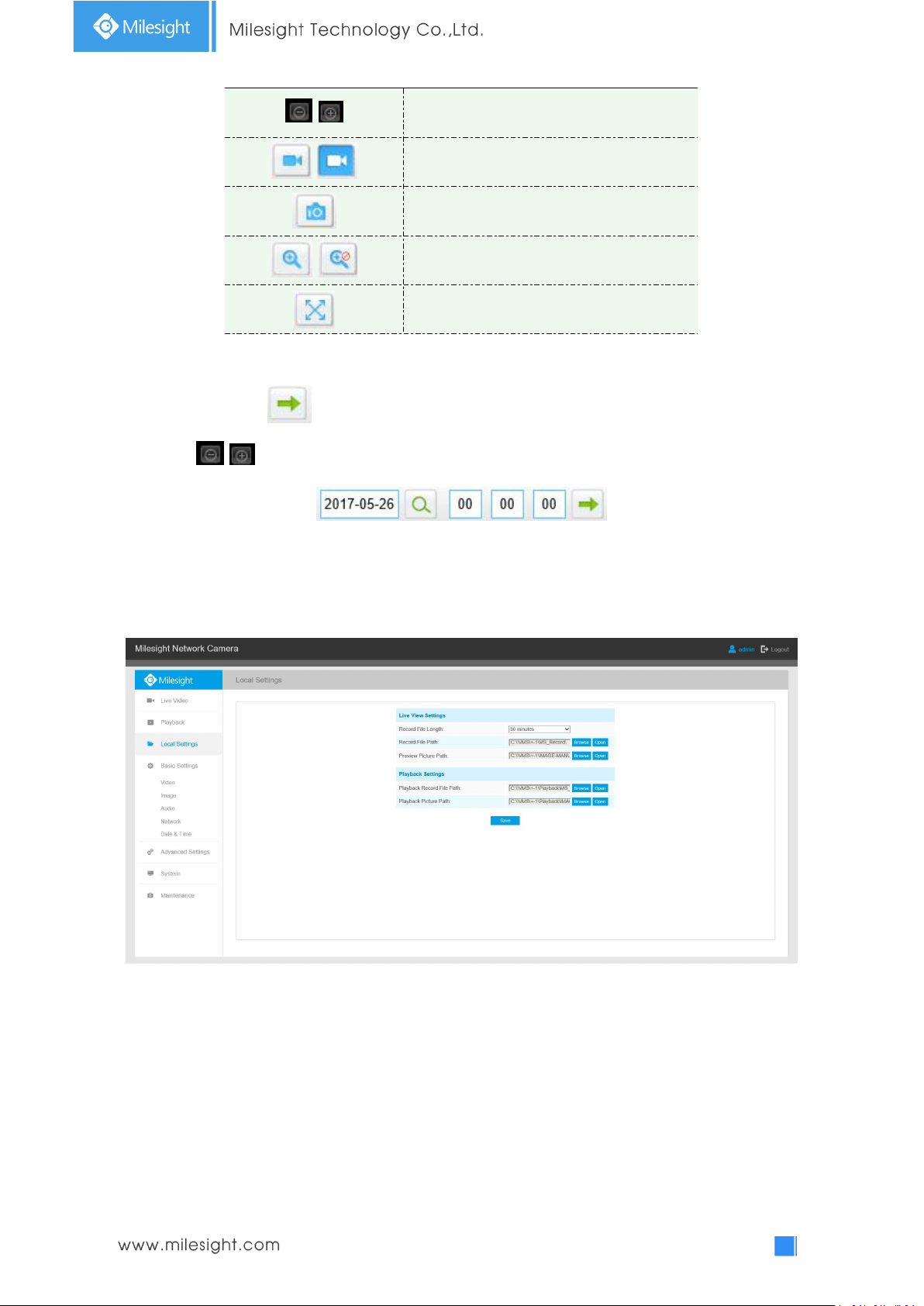
/
Time Narrow/Expand
/
Start/Stop Recording
Snapshot
/
Zoom On/Off
Full Screen
Note:
1) Drag the progress bar with the mouse to locate the exact playback point. You can also input
the time and click to locate the playback point in the Set Playback Time filed. You can
also click / to zoom out/in the progress bar.
4.3 Local Settings
Record File Length and storage path can be customized in this setting page.
4.4 Basic Settings
4.4.1 Video
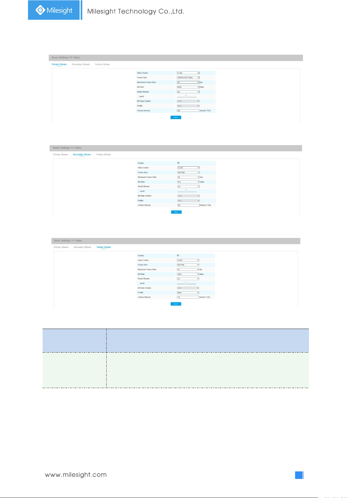
Stream parameters can be set in this module, adapting to different network environments and
demands.
Page 45
40
Primary Stream Settings
Parameters
Function Introduction
Video Codec
There are differences for the camera with “-A” and “-B”
-A: H.264/MJPEG are available
-B: H.265/H.264/MJPEG are available
Secondary Stream Settings
Tertiary Stream Settings
Table 4-4-1 Description of the buttons
Page 46

41
Frame Size
Options include 8M(3840×2160), 6M(3072×2048), 5M(2592*1944),
5M(2560*1920), 5M(2560*1440), 4M(2592*1520), 3M(2304*1296),
3M(2048*1536), 1080P(1920*1080), 2M(1600 *1200), 1.3M(1280*960),
720P(1280*720), D1(704*576).
For Secondary Stream, it includes 704*576, 640*480, 640*360, 352*288,
320*240, 320*192, 320*176.
For Tertiary Stream, it include 1920*1080, 1280*720, 704*576, 640*480,
640*360, 352*288, 320*240, 320*192, 320*176.
Maximum Frame Rate
Maximum refresh frame rate of per second
Bit Rate
Transmitting bits of data per second, this item is optional only if you select the
H.265/H.264
Smart Stream
Smart Stream mode remarkably reduces the bandwidth and the data storage
requirements for network cameras while ensuring the high quality of images, and
it is a 10-level adjustable codec.
It is optional to turn On/Off Smart Stream mode.
Level: Level 1~10 are available to meet your need.
Bit Rate Control
CBR: Constant Bitrate. The rate of CBR output is constant
VBR: Variable Bitrate. VBR files vary the amount of output date per time
segment
Image Quality
Low/Medium/High are available, this item is optional only if you select VBR.
Profile
The option is for H.264, Main/High/Base can be selected according to your needs.
I-frame Interval
Set the I-frame interval to 1~120, 50 for the default. This item is optional only if
you select the H.265/H.264. The number must be a multiple of the number of
frames.
JPEG Quality
Low/Medium/High/Higher are available,
this item is optional only if you
selected the MJPEG
Note:
1) The options of [Frame Size] are variable according to the model selected.
Page 47
42
4.4.2 Image
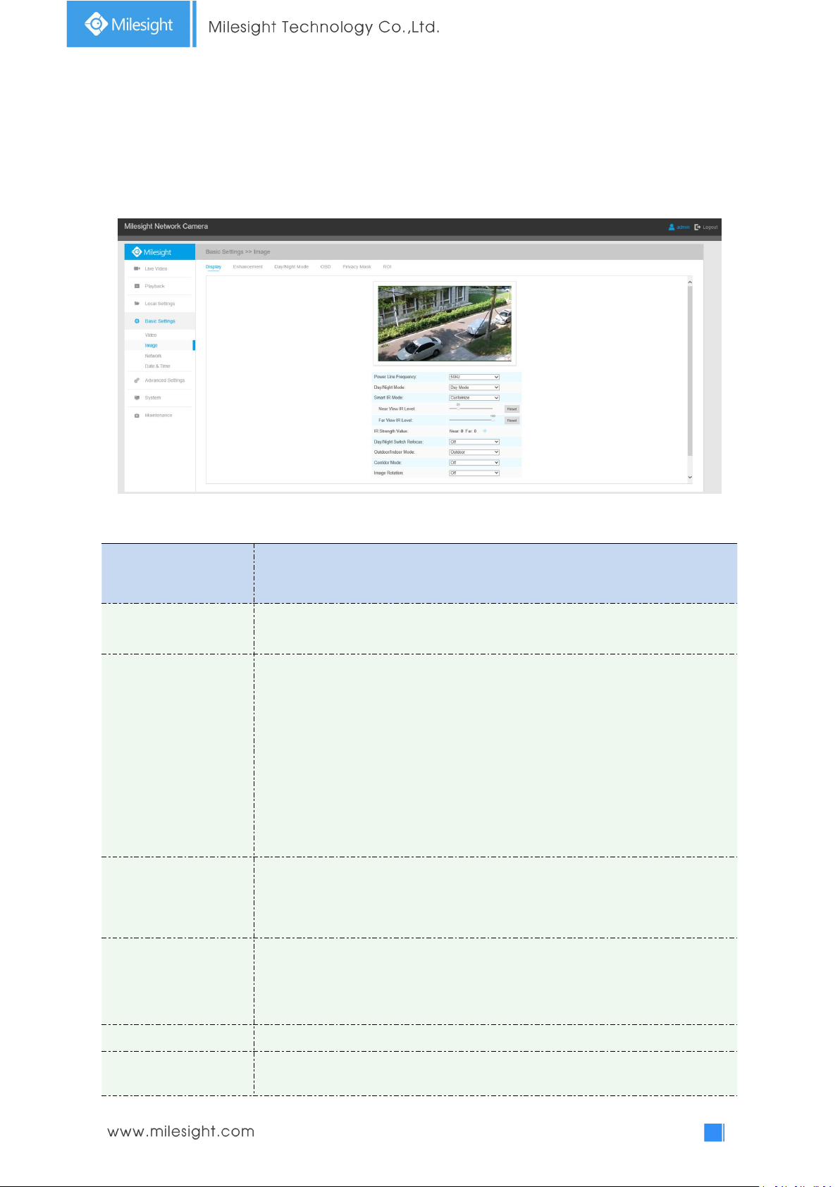
Parameters
Function Introduction
Power Line Frequency
60HZ flicker for NTSC mode and 50HZ flicker for PAL mode
Day/Night Mode
There are several parameters such as Exposure Level, Maximum Exposure Time
and IR-CUT Interval, etc, associated with this mode
Night Mode: Shown in live view based on Night Mode settings
Day Mode: Shown in live view based on Day Mode settings
Auto Mode: Shown in live view based on environment, set the sensitivity for
switching Day Mode to Night Mode, or Night Mode to Day Mode
Customize: Shown in live view based on your own settings’ time to start/end
Night Mode
Day To Night Value
This is the sensitivity for switching Day Mode to Night Mode. When IR Light
Sensor Current Value is lower than this value, it will switch Day Mode to Night
Mode
Night To Day Value
This is the sensitivity for switching Night Mode to Day Mode. When IR Light
Sensor Current Value is higher than this value, it will switch Night Mode to Day
Mode
IR Light Sensor Value
The current value of the IR light sensor
Smart IR Mode
With the combination of the High Beam and Low Beam, The IR LEDs technology
has been upgraded to provide better image clarity and quality regardless of the
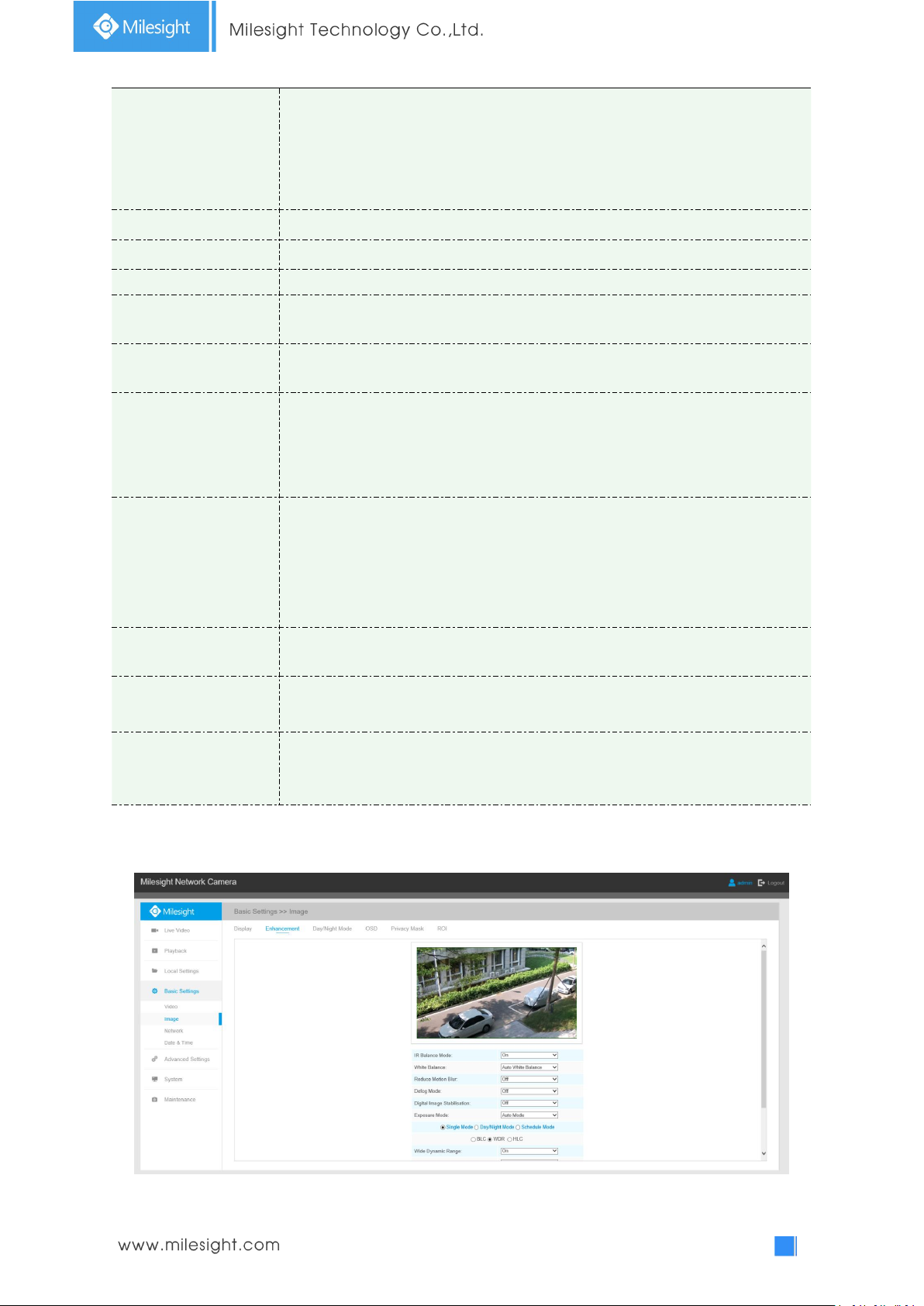
Display information, enhancement of image and Day/Night setting can be set in this module. OSD
(On Screen Display) content and video time can be displayed to rich the image information.
Display
Table 4-4-2 Description of the buttons
Page 48
43
object distance. Also, the Low Beam and High Beam's brightness can be adjusted
manually or automatically on the basis of the Zoom ratio. Moreover, with the IR
anti-reflection panel, the infrared light transmittance is highly increased.
Support to set the strength of the IR to Auto Mode or Customize to achieve the
best effect.
Near view level
Adjust the light strength of Low-Beams LED light level from 0 to 100.
Far view level
Adjust the light strength of High-Beams LED light level from 0 to 100.
IR Strength Value
The current value of Low-Beams LED and High-Beams LED light value
Day/Night Switch
Refocus
With this option enabled, the camera will refocus when switching between day
mode and night mode.
Outdoor/Indoor Mode
Select indoor or outdoor mode to meet your needs
Corridor Mode
There are three options available, you can select one to meet your need
Off: Keep the image in normal direction
Clockwise 90°: Rotate the image by 90° clockwise
Anticlockwise 90°: Rotate the image by 90° anticlockwise
Image Rotation
There are four options available, you can select one to meet your need
Off: Keep the image in normal direction
Rotating 180°: Upside down the image
Flip Horizontal: Flip the image horizontally
Flip vertical: Flip the image vertically
Local Display Video
(Only for Pro Bullet)
Select NTSC or PAL for local display
Smoked Dome Cover
This function is only for Pro Dome. If Pro Dome is equipped with a Smoked Dome
Cover, enable this function to display a normal image.
Lens distort correct
(Only for 180°
Panoramic Mini Bullet)
There are two options available, you can select one to meet your need
Off: Select the original image of 180°Panoramic Mini Bullet
On: Select the dewarping image of 180°Panoramic Mini Bullet
Enhancement
Enhancement
Page 49
44
Table 4-4-3 Description of the buttons
Parameters
Function Introduction
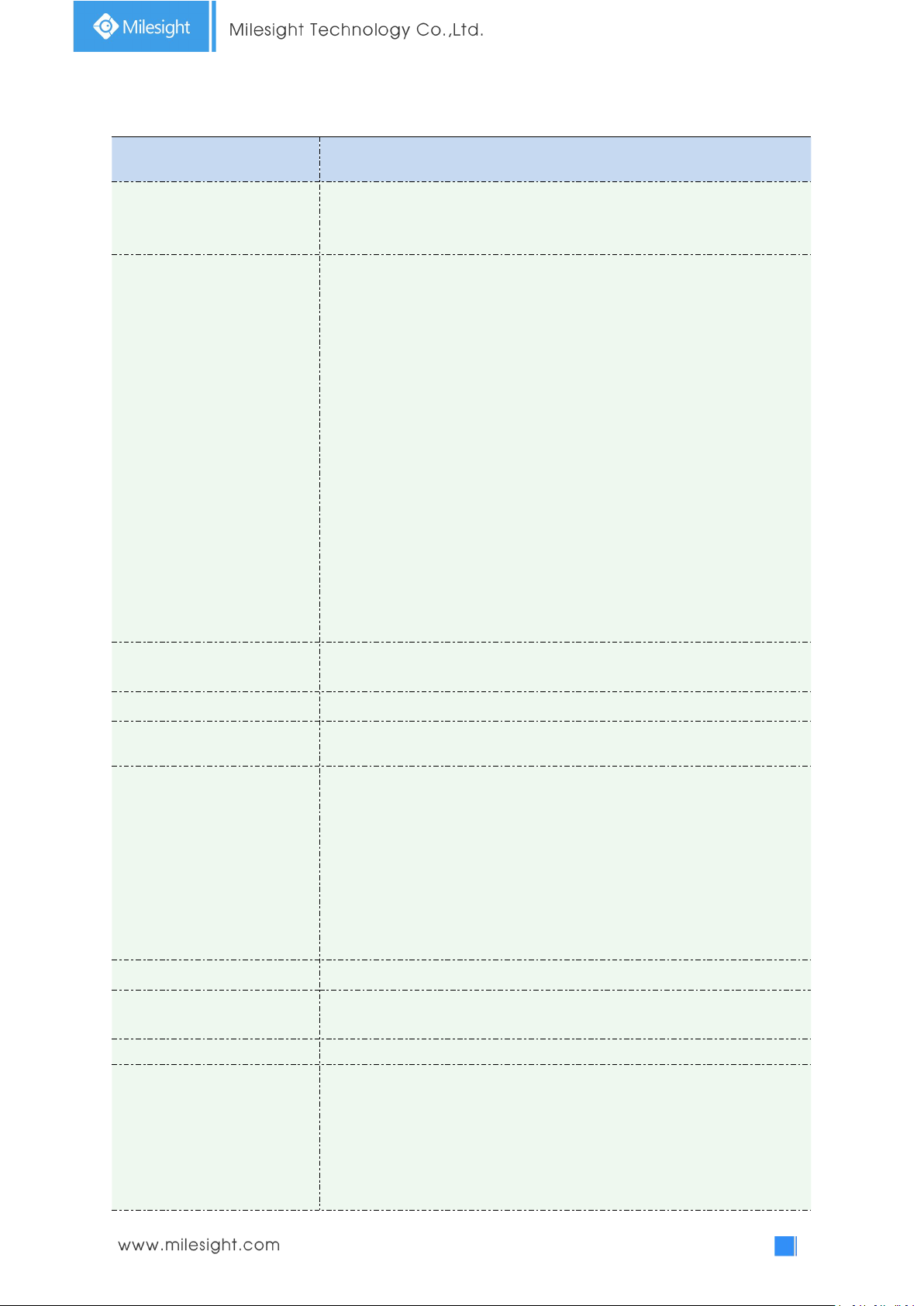
IR Balance Mode
There is an option to turn On/Off the IR LED.
IR Balance Mode would avoid the problem of overexposure and darkness,
and the IR LED will change according to the actual illumination.
White Balance
To restore white objects, removed color distortion caused by the light of
the environment
Auto White Balance: This option will automatically enable the White
Balance function
Manual White Balance: This option is only for H.265 series. Set Red Gain
Level and Blue Gain Level manually.
Incandescent Lamp: Select this option when light is similar with
incandescent lamp
Warm Light Lamp: Select this option when light is similar with warm light
lamp
Natural Light: Select this option when there is no other light but natural
light
Fluorescent Lamp: Select this option when light is similar with Fluorescent
Lamp
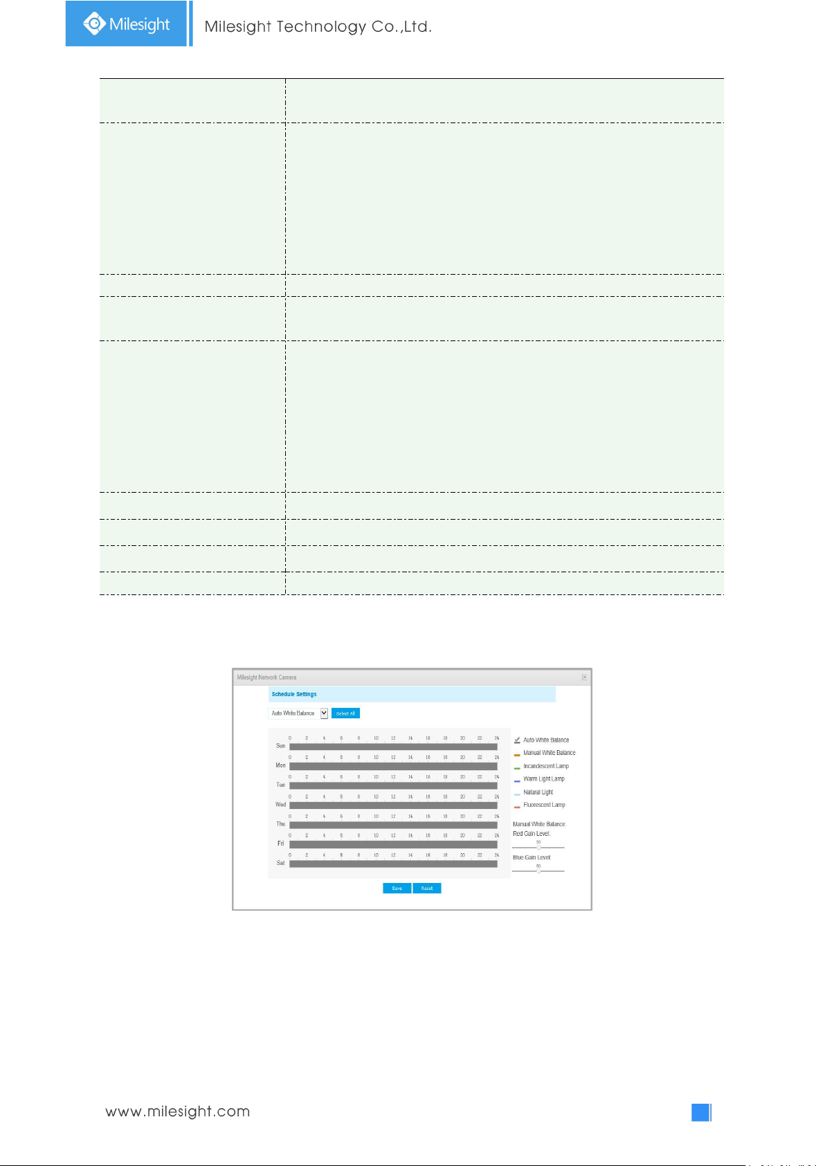
Schedule mode: Select this option that you can customize the schedule to
enable/disable above modes
Reduce Motion Blur
Enable this function to reduce the motion blur of objects effectively.
You can adjust the deblur level from 1 to 100.
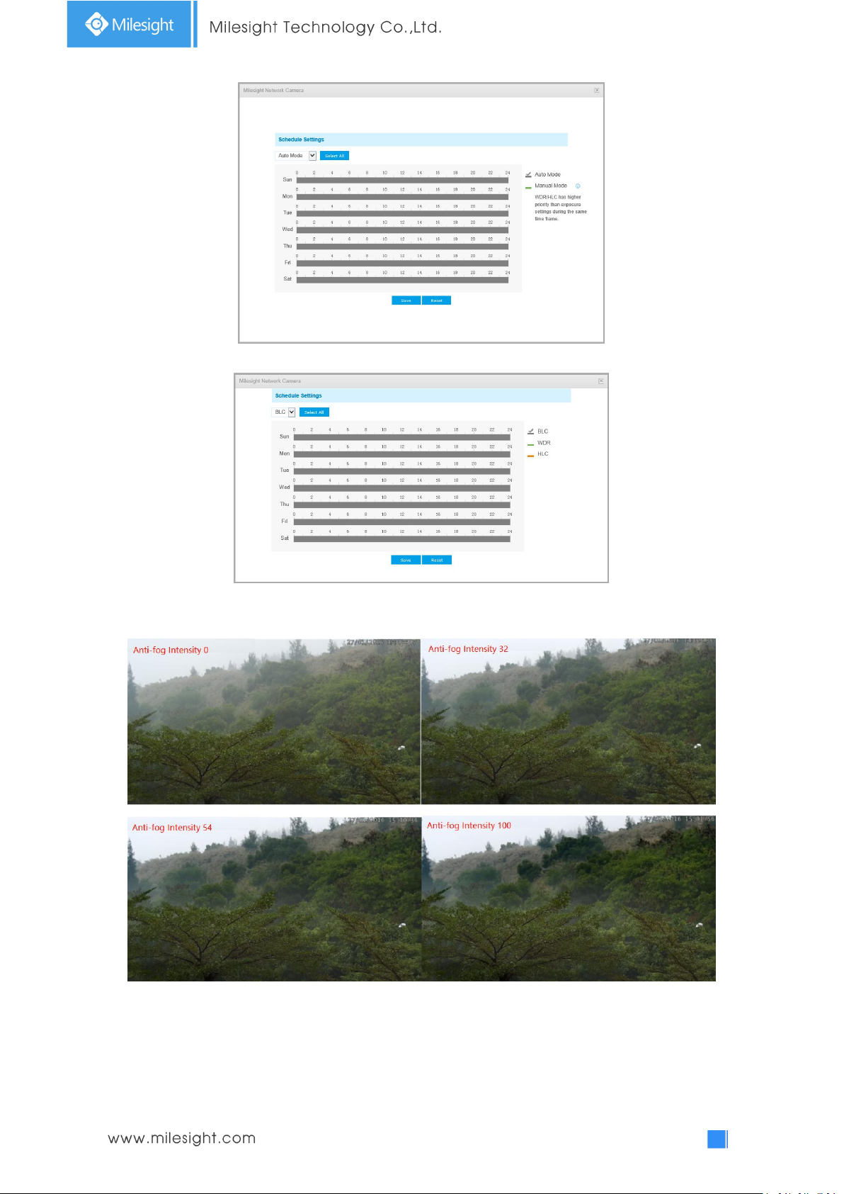
Defog Mode
Better image effect in foggy weather, refers to Figure 4-4-10
Digital Image Stabilisation
Decrease the blur and shakiness of the image.
Exposure Mode
Auto Mode, Manual Mode and Schedule Mode are available.
Auto Mode: The camera will adjust the brightness according to the light
environment automatically;
Manual Mode: The camera will adjust the brightness according to the
value you set, you can set the exposure time from 1~1/100000s, the higher
the value is, the brighter the image is;
Schedule Mode: You can customize the schedule to enable/disable Auto
Mode and Manual Mode.
Single Mode
Set single mode for BLC/WDR/HLC.
Day/Night Mode
Support BLC/WDR/HLC on Day Enhancement Mode/Night Enhancement
Mode separately.
Schedule Mode
Set schedule mode for BLC/WDR/HLC.
BLC Region
Off, Customize, and Centre are available (in single mode, only enable when
WDR is disable)
Off: Calculate the full range of view and offer appropriate light
compensation
Customize: This option enables you to customize inclusive or exclusive
region manually
Page 50
45
Centre: This option will automatically add an inclusive region in the middle
of the window and give the necessary light compensation
Wide Dynamic Range
This function which can capture and display both bright and dark areas in
the same frame enables details of objects in both bright and dark areas to
be visible.
Off: Disable WDR function
On: Enable the WDR, there are Low/High/Auto three levels
Customize: Customize the schedule to enable/disable the WDR function
and set the levels with Low/High/Auto
Wide Dynamic Level
Set WDR with Low/High/Auto level
Anti-flicker Level
Reduce flickers that appear on screen in some lighting conditions and there
are 10 levels of anti-flicker adjustments
High Light Compensation
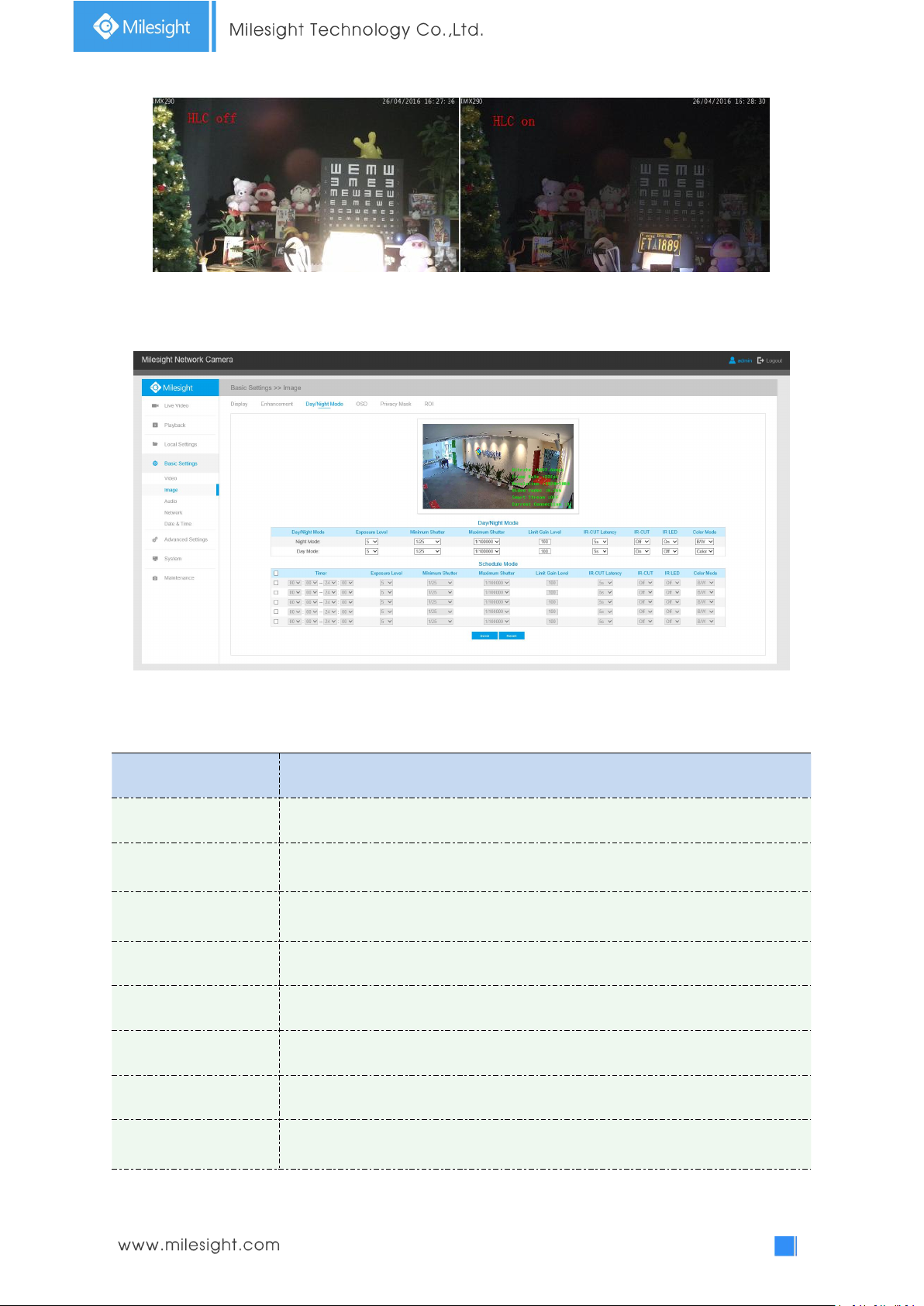
This function is only for H.265 series to adjust the brightness to a normal
range when the light is strong, refers to Figure 4-4-11
Off: Disable HLC function
General Mode: Enable the general mode of HLC, and there is a setting for
HLC Level
Enhanced Mode: Enable the enhanced mode of HLC, and there is a setting
for HLC Level
HLC Level
Select level for HLC
Day Enhancement Mode
BLC/WDR/HLC are available.
Night Enhancement Mode
BLC/WDR/HLC are available.
Schedule Setting
Customize the schedule to enable/disable BLC/WDR/HLC mode
Note:
1) You can customize the schedule to enable/disable the difference White Balance modes.
2) You can customize the schedule to enable/disable the difference exposure modes.
Page 51
46
3) You can customize the schedule to enable/disable BLC/WDR/HLC mode.
4) WDR/HLC has higher priority than exposure settings at the same time frame.
5) Defog Image.
6) HLC Image.
Page 52
47
Day/Night Mode
Parameters
Function Introduction
Exposure Level
Level 0~10 are available to meet your need
Minimum Shutter
Minimum Shutter is the same as Maximum Exposure Time. Set the minimum
Shutter to 1~1/100000s
Maximum Shutter
Maximum Shutter is the same as Minimum Exposure Time. Set the maximum
Shutter to 1~1/100000s
IR-CUT Latency
The interval time of switching one mode to another
IR-CUT
Turn on or turn off IR-CUT
IR LED
Turn on or turn off IR-LED
Color Mode
Select B/W or Color mode under Day/Night mode
Schedule Mode
Here you can customize your special demands for different time, then the Day
mode and Night mode will switch automatically according to your settings
Table 4-4-4 Description of the buttons
Page 53
48
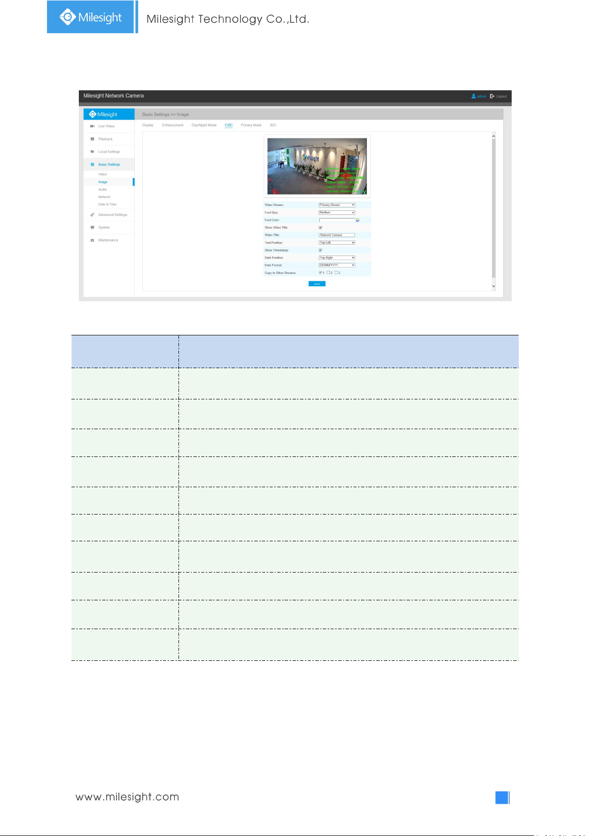
On Screen Display(OSD)
Parameters
Function Introduction
Video Stream
Enable to set OSD for primary stream and secondary stream
Font Size
Smallest/Small/Medium/Large/Largest/Auto are available for title and date
Font Color
Enable to set different color for title and date
Show Video Title
Check the checkbox to show video title
Video Title
Customize the OSD content
Text Position
OSD display position on the image
Show Timestamp
Check the checkbox to display date on the image
Date Position
Date display position on the image
Date Format
The format of date
Copy to Other Streams
Copy the settings to other streams
Table 4-4-5 Description of the buttons
Page 54
49
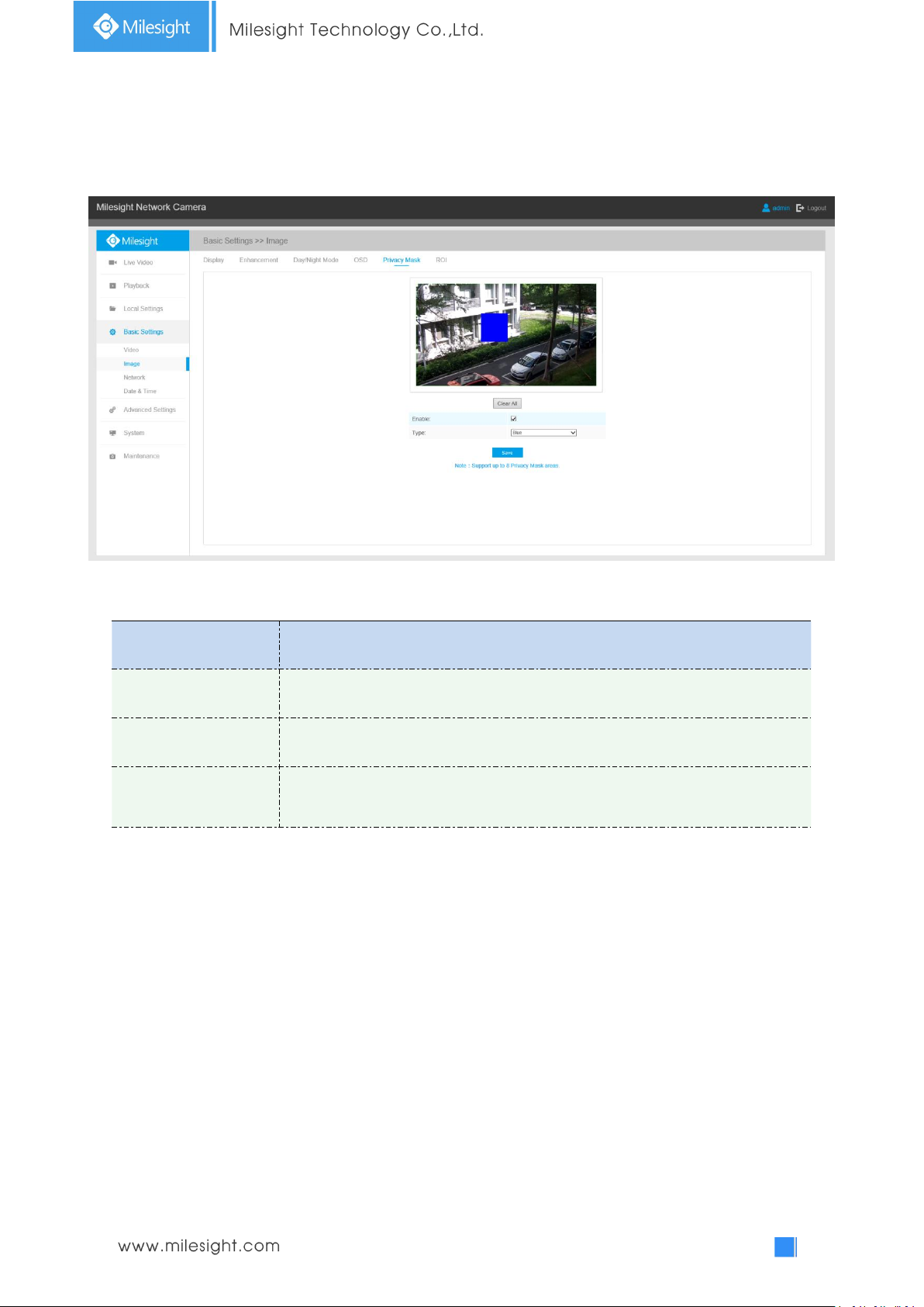
Privacy Mask
Parameters
Function Introduction
Enable
Check the checkbox to enable the Privacy Mask function
Clear All
Clear all areas you drew before
Type
Select the color to use for the privacy areas, there are eight colors available:
White, Black, Blue, Yellow, Green, Brown, Red and Violet
Privacy mask enables to cover certain areas on the live video to prevent certain spots in the
surveillance area from being viewed and recorded. You can set 8 mask areas at most.
Table 4-4-6 Description of the buttons
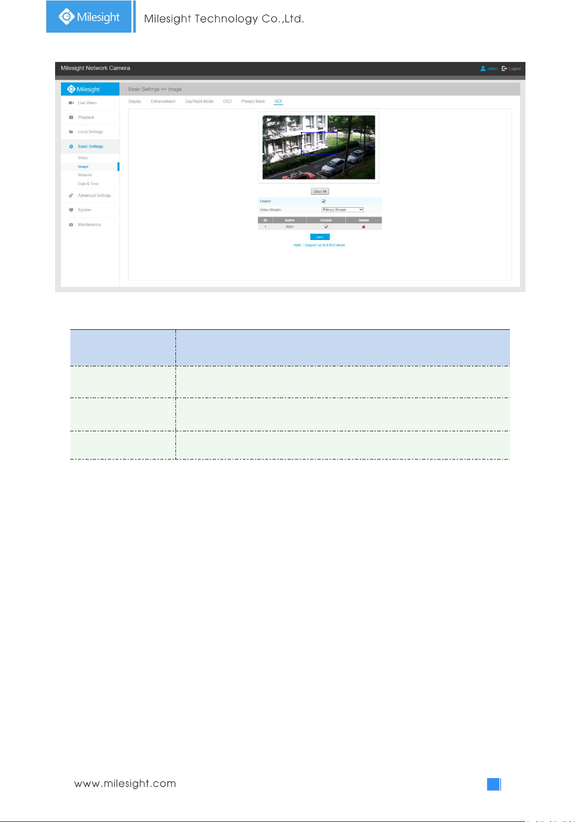
ROI
Region of interest(often abbreviate ROI), is a selected subset of samples within a dataset identified
for a particular purpose. Users can select up to 8 key regions of a scene to transmit through
separate streams for targeted preview and recording.
By using Milesight ROI technology, more than 50% of bit rate can be saved and therefore less
bandwidth demanded and the storage usage reduced. So according to this, you can set a small bit
rate for high resolution.
Page 55
50
Table 4-4-7 Description of the buttons
Parameters
Function Introduction
Enable
Check the checkbox to enable the ROI function
Clear All
Clear all areas you drew before
Video Stream
Choose the Video Stream
Note:
You can set a low bit rate. For example, you can set a bit rate with 512Kbps and a resolution with
1080P, then you can see the image quality of ROI is more clear and fluent than the other region.
4.4.3 Audio
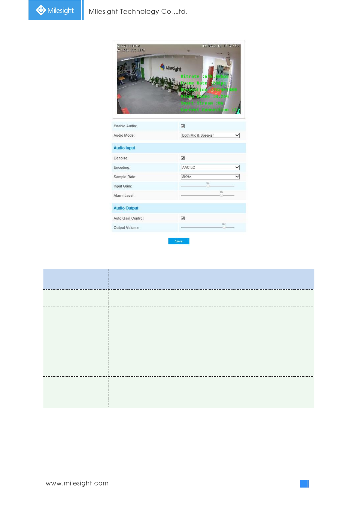
This audio function allows you to hear the sound from the camera or transmit your sound to the
camera side. A two-way communication is also possible to be achieved with this feature. Alarm can
be triggered when the audio input is above a certain alarm level you set, and configured audio can
be played when an alarm occurs.
Page 56
51
Table 4-4-8 Description of the buttons
Parameters
Function Introduction
Enable Audio
Check on the checkbox to enable audio feature
Audio Input
Denoise: Set it as On/Off. When you set the function on, the noise detected can
be filtered
Encoding: G711-ULaw, G711-ALaw and AAC LC are available
Sample Rate: There are 8KHz/16KHz two options
Input Gain: Input audio gain level, 0-100
Alarm Level: Alarm will be triggered if voice alarm is enabled and input gained
volume is higher than the alarm level, 1-100
Audio Output
Auto Gain Control: This function is only for H.265 series, improve the quality of
audio
Output Volume: Adjust volume of output
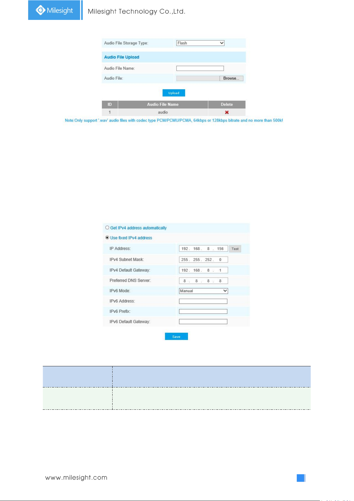
You can upload up to 5 audio files manually to Flash or SD Card on the Audio web page and you
can also edit the audio file’s name when upload.
Page 57
52
Note:
Parameters
Function Introduction
Get IPv4 Address
Automatically
Get an IP address from the DHCP server automatically
1) The Audio mode and Audio Output are only for certain modules.
2) Only support ‘.wav’ audio files with codec type PCM/PCMU/PCMA, 64kbps or 128 kbps and no
more than 500k.
4.4.4 Network
TCP/IP
Table 4-4-9 Description of the buttons
Page 58
53
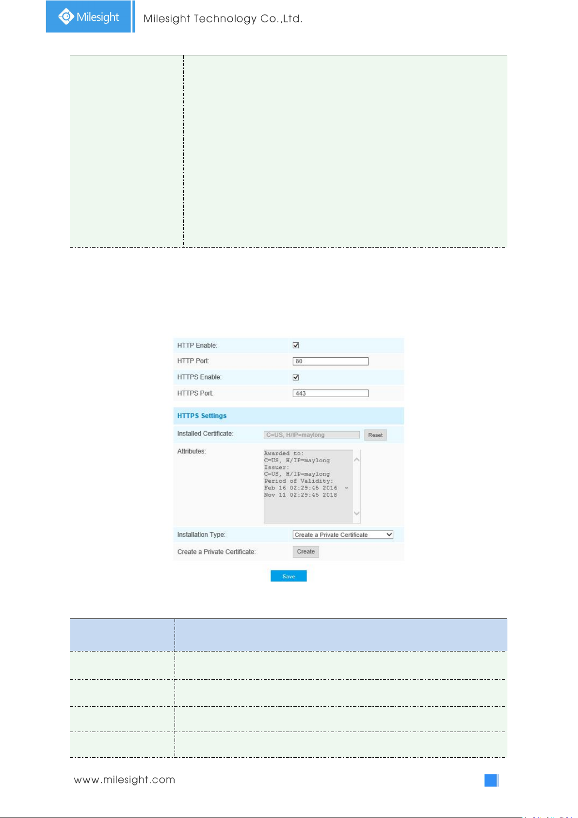
Use fixed IP address
IPv4 Address: An address that used to identify a network camera on the
network
IPv4 Subnet Mask: It is used to identify the subnet where the network camera
is located
IPv4 Default Gateway: The default router address
Preferred DNS Server: The DNS Server translates the domain name to IP
address
IPv6 Mode: Choose different mode for IPv6: Manual/Route Advertisement/
DHCPv6
IPv6 Address: IPv6 Address used to identify a network camera on the network
IPv6 Prefix: Define the prefix length of IPv6 address
IPv6 Default Gateway: The default router IPv6 address
Note:
Parameters
Function Introduction
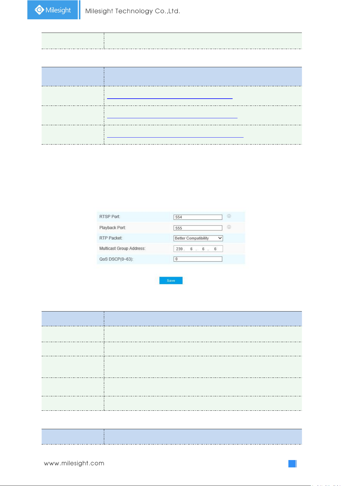
HTTP Enable
Start or stop using HTTP
HTTP Port
Web GUI login port, the default is 80, the same with ONVIF port
HTTPS Enable
Start or stop using HTTPS
HTTPS Port
Web GUI login port via HTTPS, the default is 443
The Test button is used to test if the IP is conflicting.
HTTP
Table 4-4-10 Description of the buttons
Page 59
54
HTTP Settings
Upload and set the SSL certificate .
HTTP URL are as below:
Stream
URL
Main Stream
http://username:password@IP:port/ipcam/mjpeg.cgi
Secondary Stream
http://username:password@IP:port/ipcam/mjpegcif.cgi
Tertiary Stream
http://username:password@IP:port/ipcam/mjpegthird.cgi
Parameters
Function Introduction
RTSP Port
The port of RTSP, the default is 554
Playback Port
The port of playback, the default is 555
RTP Packet
There are Better Compatibility and Better Performance two options, if your
camera’s image mess up, please switch this option
Multicast Group
Address
Support multicast function
QoS DSCP
The valid value range of the DSCP is 0-63.
Stream
URL
Note:
You need to change the codec type of streams to MJPEG except the main stream of H.264
cameras whose models with “-A”.
RTSP
Table 4-4-11 Description of the buttons
RTSP URL are as below:
Page 60
55
Main Stream
rtsp://username:password@IP:port/main
Secondary Stream
rtsp://username:password@IP:port/sub
Tertiary Stream
rtsp://username:password@IP:port/third
Note:
Parameters
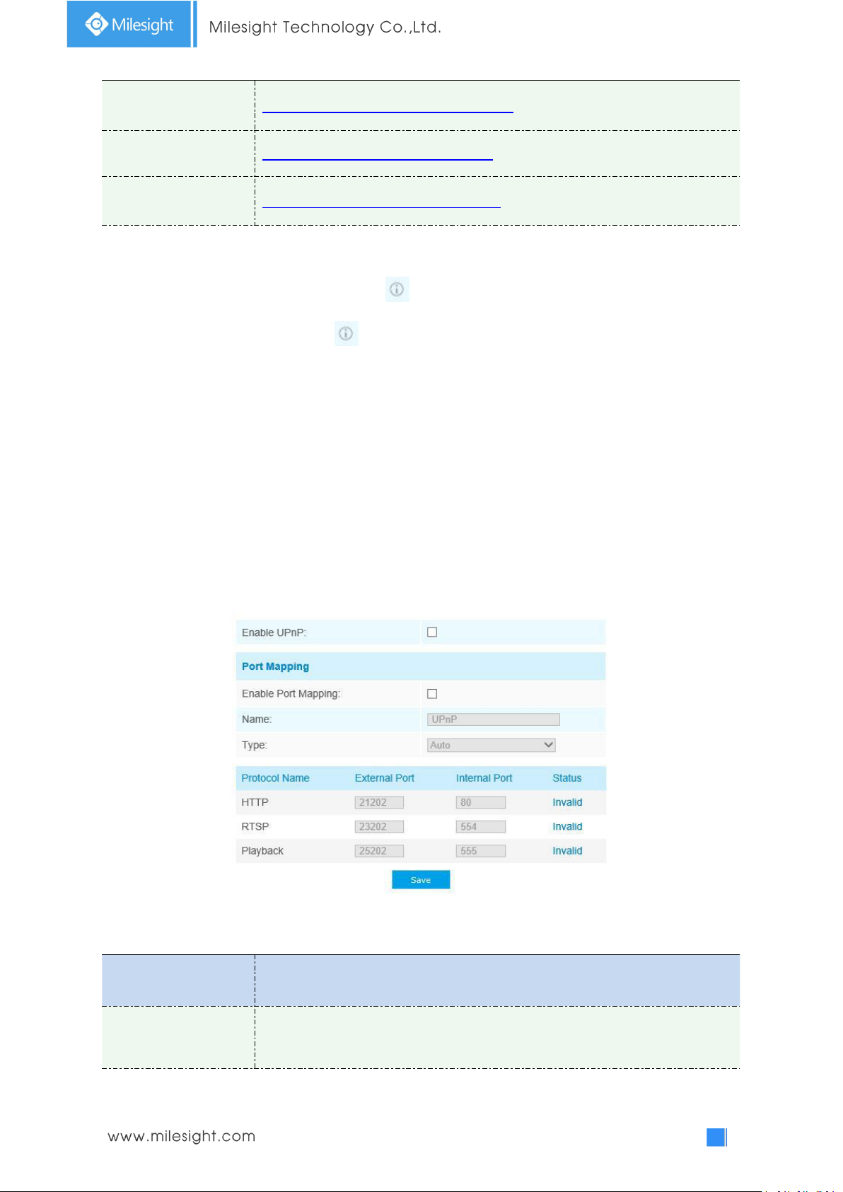
Function Introduction
Enable
Check the checkbox to enable the UPnP function
1) Get the format of RTSP URL by clicking “ ”on the right side of RTSP Port.
2) Get the playback tip by clicking “ ”on the right side of Playback Port.
3) DSCP refers to the Differentiated Service Code Point; and the DSCP value is used in the IP
header to indicate the priority of the data.
4) A reboot is required for the settings to take effect.
5) The tertiary stream is only equipped on camera whose model with “-A” or “-B”.
UPnP
Universal Plug and Play (UPnP) is a networking architecture that provides compatibility among
networking equipment, software and other hardware devices. The UPnP protocol allows devices
to connect seamlessly and to simplify the implementation of networks in the home and corporate
environments. With the function enabled, you don’t need to configure the port mapping for each
port, and the camera is connected to the Wide Area Network via the router.
Table 4-4-12 Description of the buttons
Page 61
56
Enable Port Mapping
Check the checkbox to enable the Port Mapping
Name
The name of the device detected online can be edited
Type
Auto: Automatically obtain the corresponding HTTP and RTSP port, without any
settings
Manual: Need to manually set the appropriate HTTP port and RTSP Port. When
choose Manual, you can customize the value of the port number by yourself
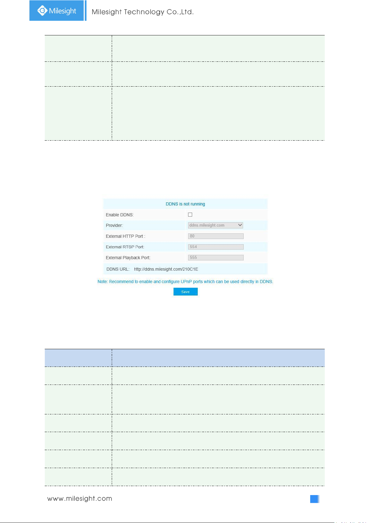
DDNS
Parameters
Function Introduction
Enable DDNS
Check the checkbox to enable DDNS service
Provider
Get support from DDNS provider: ddns.milesight.com, freedns.afraid.org,
dyndns.org, www.no-ip.com, www.zoneedit.com. You can also customize the
provider for DDNS.
Hash
A string used for verifying, only for "freedns.afraid.org"
User name
Account name from the DDNS provider, unavailable for "freedns.afraid.org"
Password
Account password, unavailable for "freedns.afraid.org"
Host name
DDNS name enabled in the account
DDNS allows you to access the camera via domain names instead of IP address. It manages to
change IP address and update your domain information dynamically. You need to register an
account from a provider.
You can choose “ddns.milesight.com” as provider for DDNS. After enabling it, you can access the
device via the URL “http://ddns.milesight.com/MAC address” .
Table 4-4-13 Description of the buttons
Page 62
57
Note:
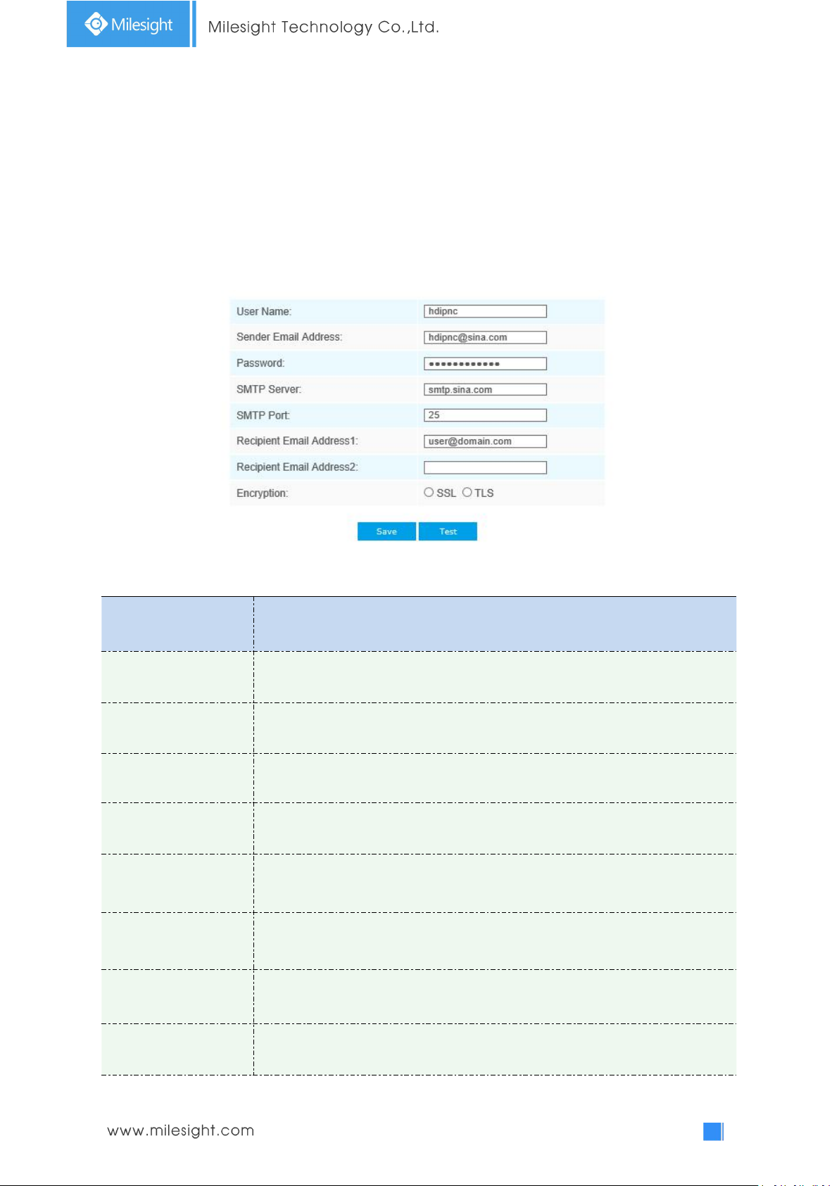
Parameters
Function Introduction
User Name
The sender's name. It is usually the same as the account name
Sender Email Address
Email address to send video files attached emails
Password
The password of the sender
SMTP Server
The SMTP server IP address or host name(e.g. smtp.gmail.com)
SMTP Port
The default TCP/IP port for SMTP is 25(not secured). For SSL/TLS port, it depends
on the mail you use
Recipient Email
Address1
Email address to receive video files
Recipient Email
Address2
Email address to receive video files
Encryption
Check the checkbox to enable SSL or TLS if it is required by the SMTP server.
1)Please do the Port Forwarding of HTTP Port and RTSP Port before you use Milesight DDNS.
2)Make sure that the internal and the external port number of RTSP are the same.
Email
Alarm video files can be sent to specific mail account through SMTP server. You must configure the
email settings correctly before using it.
Table 4-4-14 Description of the buttons
Page 63
58
FTP
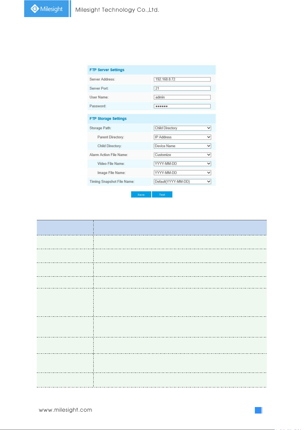
Parameters
Function Introduction
Server Address
FTP server address
Server Port
The port of the FTP server. Generally it is 21
User Name
User name used to log in to the FTP sever
Password
User password
Storage Path
Storage Path where video and image will be uploaded to the FTP server.
Four FTP storage path types are available, including Root Directory, Parent
Directory, Child Directory and Customize.
Parent Directory
Choose IP Address/ Device Name/ Date as the folder name of Parent Directory,
or customize the folder name.
Child Directory
Choose IP Address/ Device Name/ Date as the folder name of Child Directory, or
customize the folder name.
Multilevel Folder Name
If the storage path is more than two levels, enter Multilevel FTP storage path
here manually.
Alarm Action File Name
Choose the default(YYYY-MM-DD) or customize the alarm action file name.
Alarm video files can be sent to specific FTP server. You must configure the FTP settings correctly
before using it.
Table 4-4-15 Description of the buttons
Page 64
59
Video File Name
If you choose to customize the alarm action file name, YYYY-MM-DD/
MM-DD-YYYY/ DD-MM-YYYY/ Add prefix are available.
Image File Name
If you choose to customize the alarm action file name, YYYY-MM-DD/
MM-DD-YYYY/ DD-MM-YYYY/ Add prefix are available.
Timing Snapshot File
Name
Default(YYYY-MM-DD) /MM-DD-YYYY/ DD-MM-YYYY/ Add prefix/ Overwrite with
the base file name are available.
Note:
Parent Directory will be under Root Directory, and Child Directory will be under Parent
Directory.
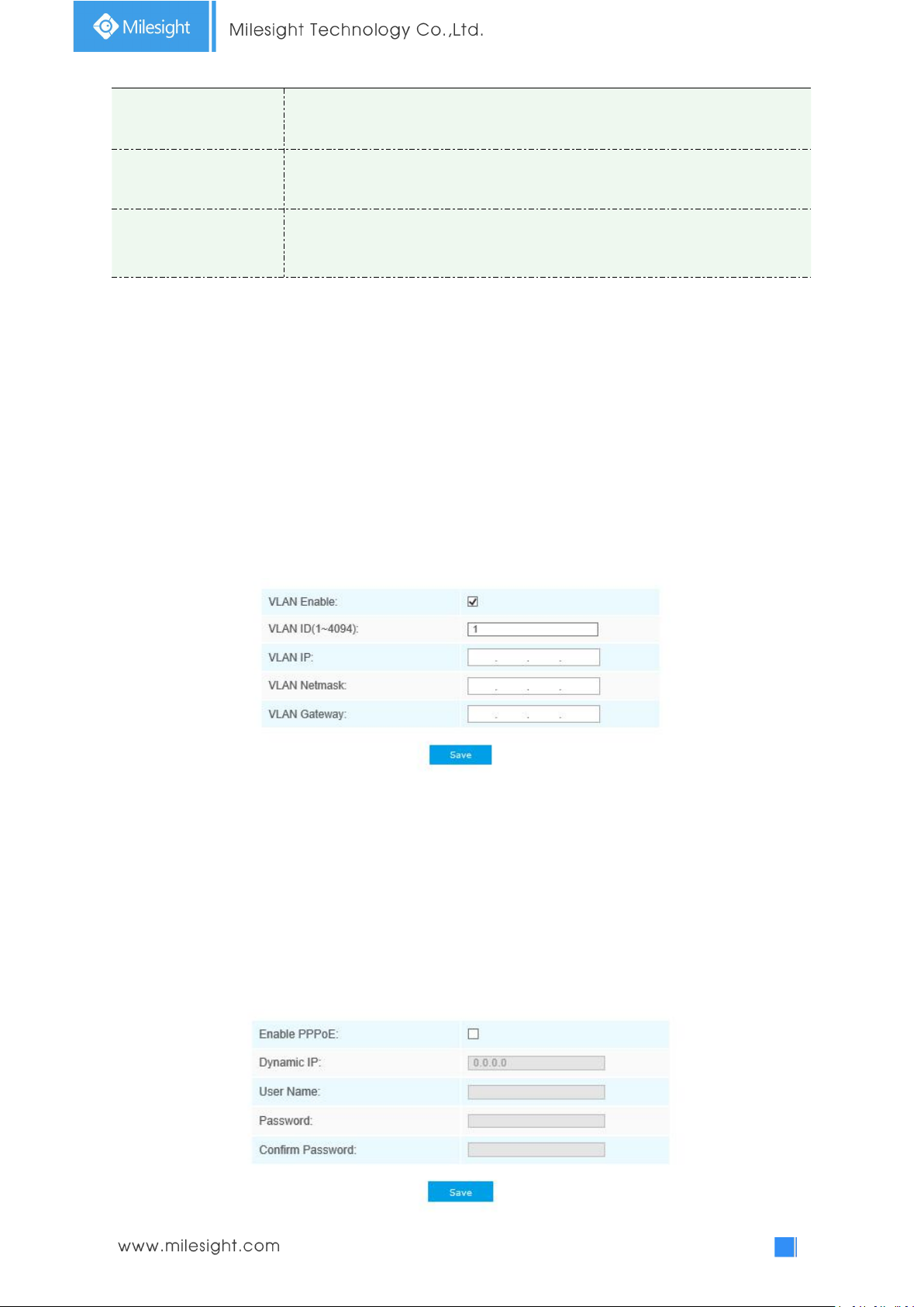
VLAN
A virtual LAN (VLAN) is any broadcast domain that is partitioned and isolated in a computer
network at the data link layer (OSI layer 2). LAN is an abbreviation of local area network. VLANs
allow network administrators to group hosts together even if the hosts are not on the same
network switch. This can greatly simplify network design and deployment, because VLAN
membership can be configured through software. Without VLANs, grouping hosts according to
their resource needs necessitates the labour of relocating nodes or rewiring data links.
Note:
How to set up VLAN in switches, please refers to your switches user manual.
PPPoE
This camera supports the PPPoE auto dial-up function. The camera gets a public IP address by ADSL
dial-up after the camera is connected to a modem. You need to configure the PPPoE parameters of
the network camera.
Page 65
60
Note:
Parameters
Function Introduction
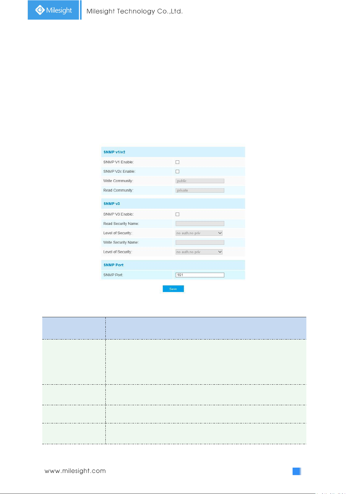
SNMP v1/2/3
The version of SNMP, please select the version of your SNMP software.
SNMP v1: Provide no security
SNMP v2: Require password for access
SNMP v3: Provide encryption and the HTTPS protocol must be enabled
Write Community
Input the name of Write Community
Read Community
Input the name of Read Community
Read Security Name
Input the name of Read Security Community
1) The obtained IP address is dynamically assigned via PPPoE, so the IP address always changes
after rebooting the camera. To solve the inconvenience of the dynamic IP, you need to get a
domain name from the DDNS provider (e.g. DynDns.com).
2) The user name and password should be assigned by your ISP.
SNMP
You can set the SNMP function to get camera status, parameters and alarm related information
and manage the camera remotely when it is connected to the network.
Before setting the SNMP, please download the SNMP software and manage to receive the camera
information via SNMP port. By setting the Trap Address, the camera can send the alarm event and
exception messages to the surveillance center.
Table 4-4-16 Description of the buttons
Page 66
61
Level of Security
There are three levels available: (auth, priv), (auth, no priv) and (no auth, no priv)
Write Security Name
Input the name of Write Security Community
Level of Security
There are three levels available: (auth, priv), (auth, no priv) and (no auth, no priv)
SNMP Port
The port of SNMP, the default is 161
Note:
1) The settings of SNMP software should be the same as the settings you configure here;
2) A reboot is required for the settings to take effect.
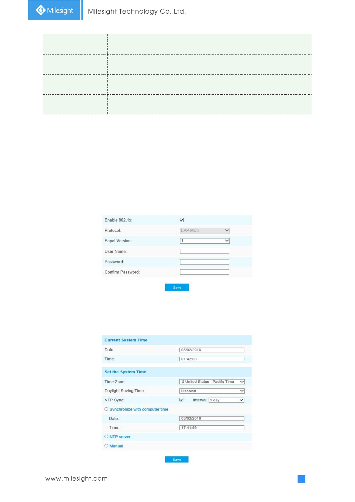
802.1x
The IEEE 802.1X standard is supported by the network cameras, and when the feature
is enabled, the camera data is secured and user authentication is needed when
connecting the camera to the network protected by the IEEE 802.1X.
4.4.5 Date&Time
Page 67
62
Current System Time
Parameters
Function Introduction
Time Zone
Choose a time zone for your location
Daylight Saving time
Enable the daylight saving time
NTP Sync
Regularly update your time according to the interval time
Synchronize with
computer time
Synchronize the time with your computer
NTP server
Input the address of NTP server
Manual
Set the system time manually
Current date&time of the system
Set the System Time
Table 4-4-17 Description of the buttons
4.5 Advanced Settings
4.5.1 Alarm
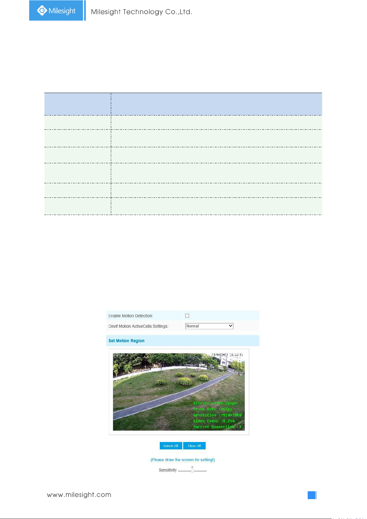
Motion Detection
Step1: Check the checkbox to enable the motion detection;
Step2: Set motion region;
Page 68
63
Table 4-5-1 Description of the buttons
Parameters
Function Introduction
Enable Motion
Detection
Check the checkbox to enable Motion Detection function
Onvif Motion
ActiveCells Settings
Normal and Compatible are available for the option. If the setting of motion
region of the third-party software is different from ours, please set this option to
Compatible.
Select All
Click the button, the motion in the area will be detected
Clear All
Click the button, the area drawn before will be removed
Sensitivity
Sensitivity level, 1~10
Parameters
Function Introduction
Save Into Storage
Save alarm recording files into SD Card or NAS
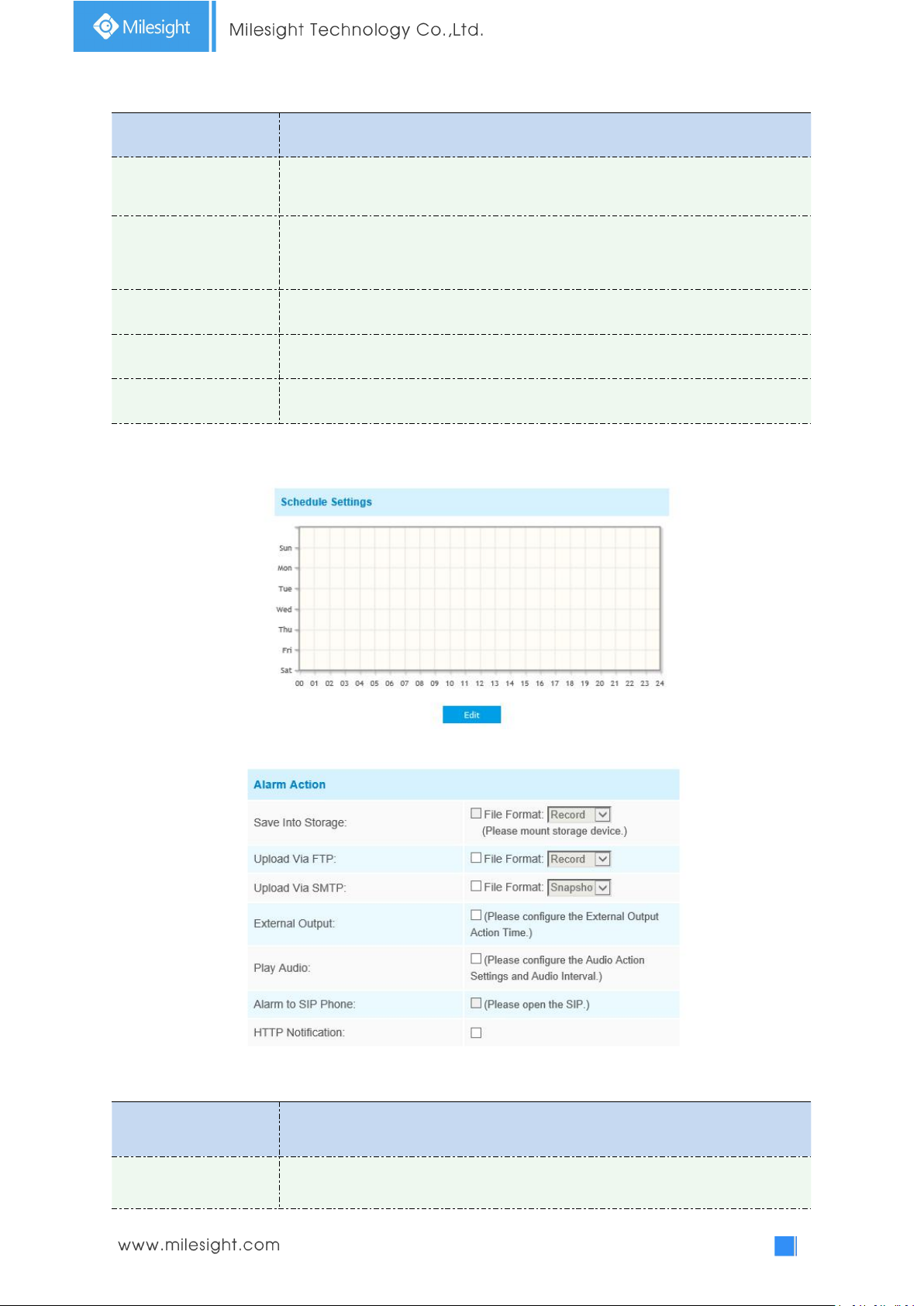
Step3: Set motion detection schedule;
Step4: Set alarm action;
Table 4-5-2 Description of the buttons
Page 69
64
Upload Via FTP
Upload the recording files via FTP
Upload Via SMTP
Upload the files via SMTP
External Output
If the camera equips with External Output, you can enable the action after
configuring the trigger duration
Play Audio
If the camera equips with Speaker, you can enable the action after configuring the
audio speaker
Play Buzzer
If the camera equips with Buzzer, you can check the checkbox to enable the
function.
Alarm to SIP Phone
Support to call the SIP phone after enable the SIP function.
HTTP Notification
Support to pop up the alarm news to specified HTTP URL.
Note: Three HTTP notifications at most can be added to the same event.
NOTE:
1) The HTTP notification function is just one way for camera to send messages to VMS Software.
And it's the VMS that defines what the messages mean and decides what to do after receiving
this kind of messages. So, we can use the HTTP Notification function of our cameras only if the
VMS supports this kind of message format.
Here will take the Digifort as an example to introduce the HTTP Notification function.
The following are the detail steps of setting for HTTP Notification in Digifort VMS and our
cameras.
Step1: Enable Alarm, set Motion Region and detection Schedule;
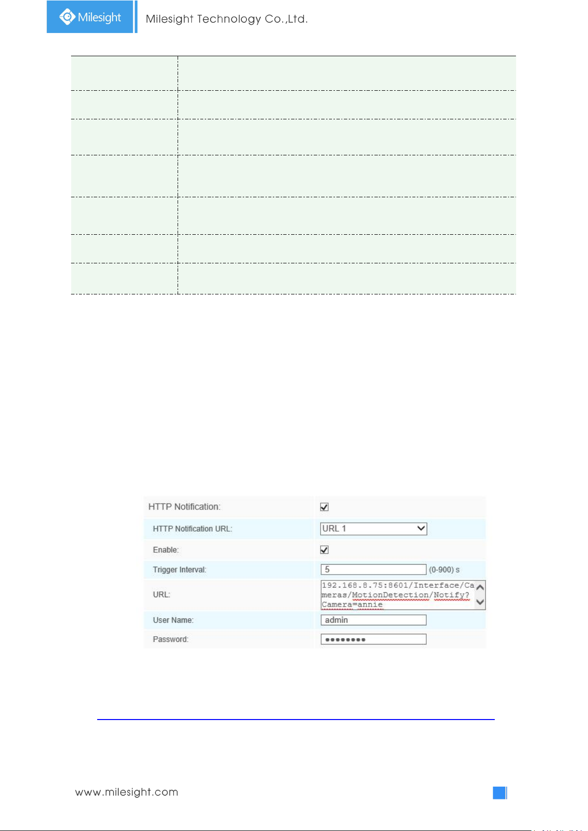
Step2: Check the HTTP Notification as Alarm Action, and fill the fields. Then save the
alarm setting. You can add up to three HTTP notifications to the same event;
HTTP User Name: admin (the user name of your camera)
HTTP Password: ms1234 (the password of your camera)
HTTP Notification URL:
http://IP:8601/Interface/Cameras/MotionDetection/Notify?Camera=CameraName
IP refers to the PC's IP where the Digifort installed.
8601 is the port for Motion signal in Digifort.
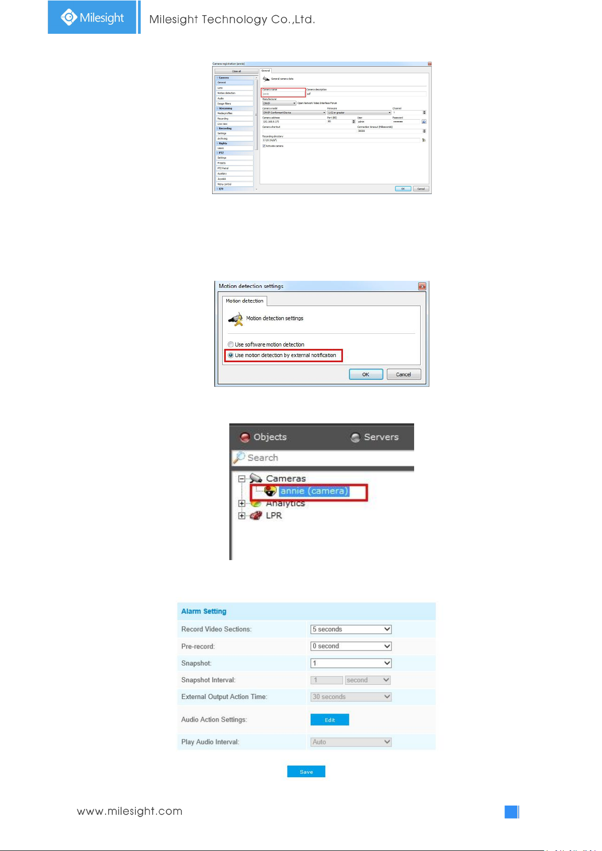
CameraName is the camera name you set in Digifort VMS, like the picture shown below.
Page 70
65
Example:
http://192.168.8.75:8601/Interface/Cameras/MotionDetection/Notify?Camera=annie,
this URL format is exactly supported by Digifort VMS, so we can set as above to our
cameras and get it work well.
Step3: choose use motion detection by external notification;
Step4: If successful, you can see the device icon turns yellow in the Surveillance when the
camera is under Motion Detection Alarm;
So, it's the VMS Software which decides whether we can use this function successfully.
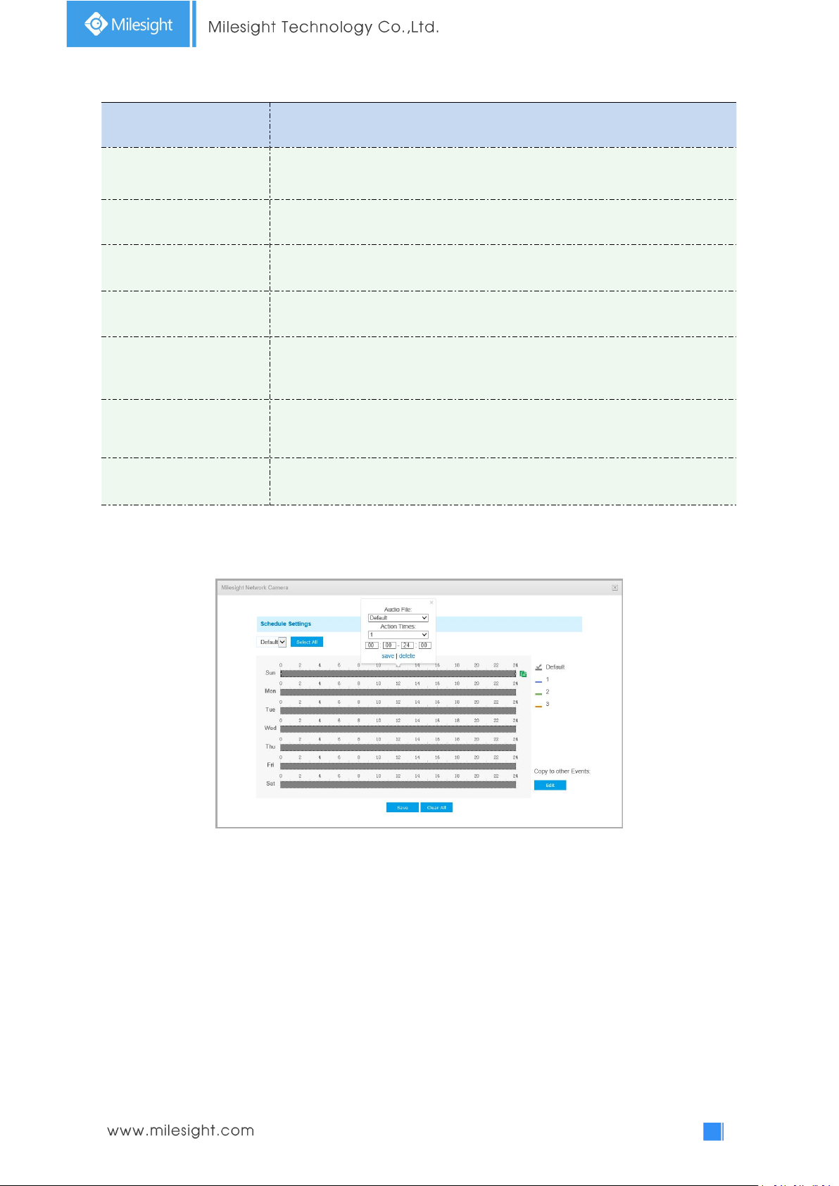
Step5: Set alarm settings.
Page 71
66
Table 4-5-3 Description of the buttons
Parameters
Function Introduction
Record Video Sections
Six different periods are available(5, 10, 15, 20, 25, 30 sec)
Pre-record
Reserve the record time before alarm, 0~10 sec
Snapshot
The number of snapshot, 1~5
Snapshot Interval
This cannot be edited unless you choose more than 1 to Snapshot
External Output Action
Time
Length of time an alarm lasts, this cannot be edited unless you enable the
External Output on the Alarm Action firstly.
Audio Action Settings
Set the audio schedule to trigger different audio files and action times in
different time, which is corresponded to alarm action.
Play Audio Interval
Auto/ 10 seconds/ 30 seconds/ 1 minute/ 5 minutes/ 10 minutes are available.
Note:
You can customize the schedule of Audio Action.
Audio Alarm
Enable the Audio before using Audio Alarm function.
Page 72
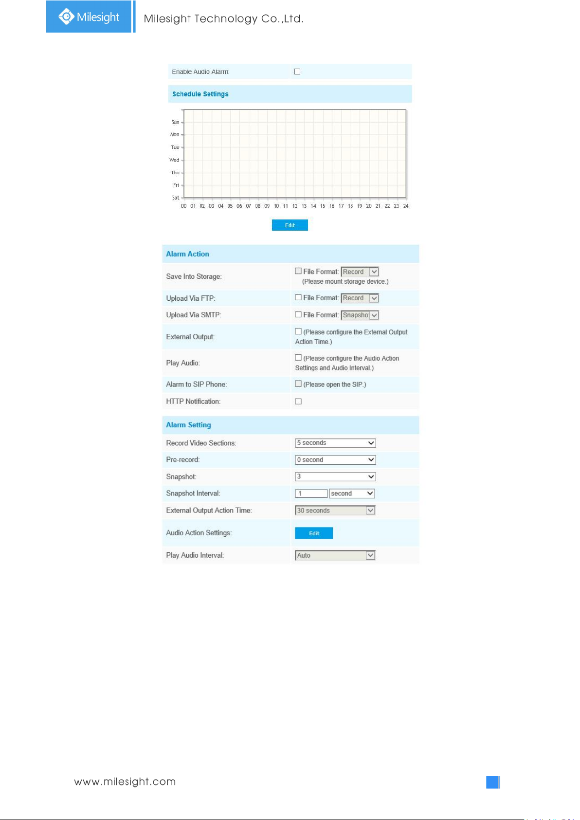
67
The meaning of items please refer to table 4-5-2 and 4-5-3, here will not repeat again.
Page 73
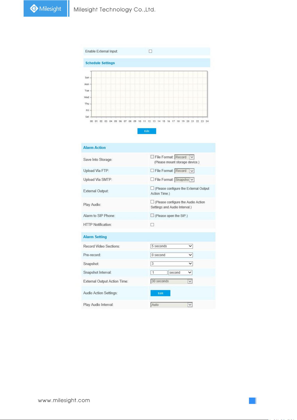
68
External Input
The meaning of items please refer to table 4-5-2 and 4-5-3, here will not repeat again.
Page 74
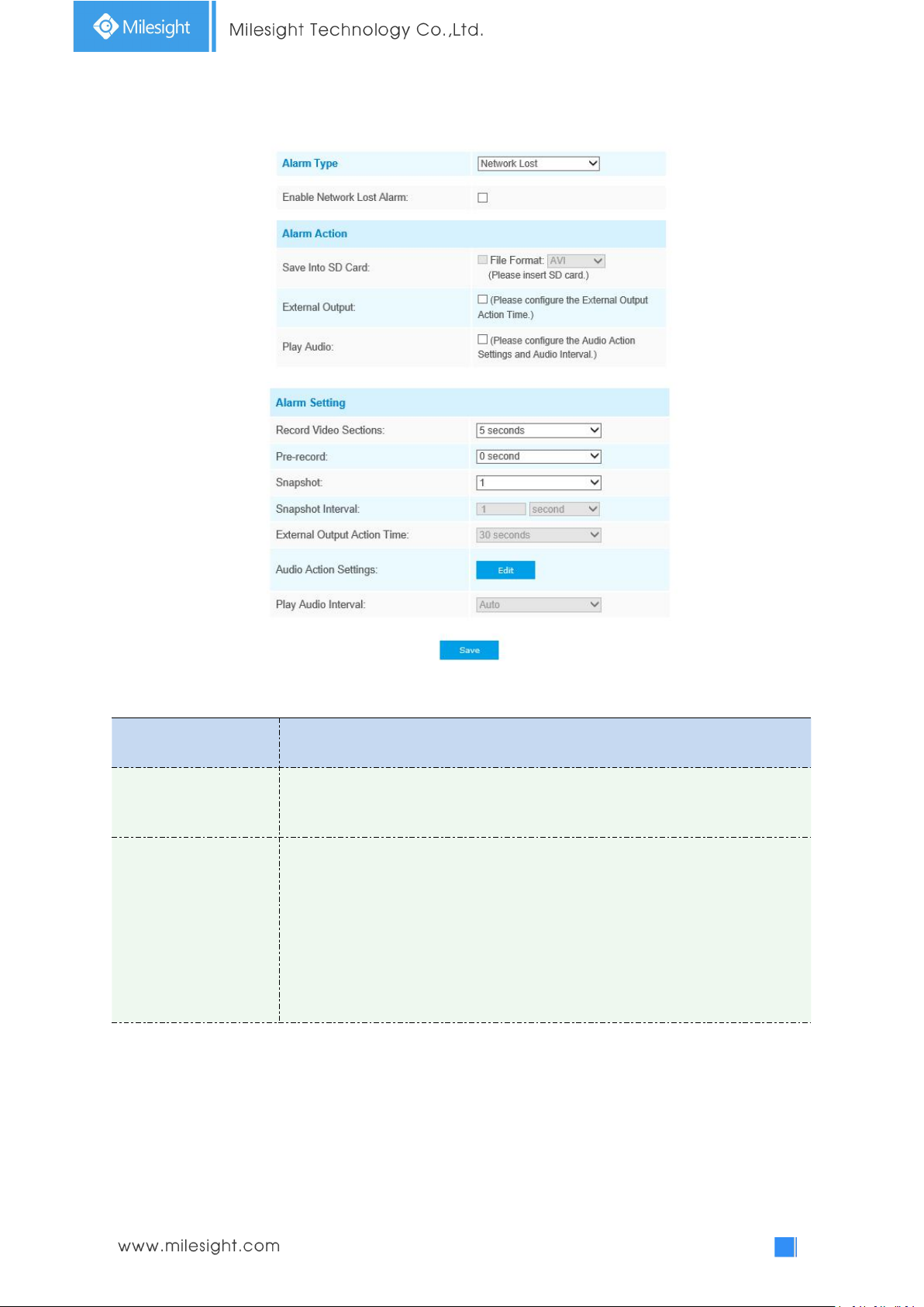
69
Other Alarm
Parameters
Function Introduction
Alarm Type
Network Lost, Tampering and IP Address Conflicted are available
Check the checkbox to enable the alarm type you selected
Alarm Action
Save Into SD Card: Save alarm recording files into SD Card
External Output: If the camera equips with External Output, you can enable the
action after configuring the trigger duration
Play Audio: If the camera equips with Speaker, you can enable the action after
configuring the audio speaker
Play Buzzer: If the camera equips with Buzzer, you can check the checkbox to
enable the function
Table 4-5-4 Description of the buttons
Page 75
70
Alarm Setting
Record Video Sections: Six different periods are available(5, 10, 15, 20, 25, 30
sec)
Pre-record: Reserve the record time before alarm, 0~10 sec
Snapshot: The number of snapshot, 1~5
Snapshot Interval: This cannot be edited unless you choose more than 1 to
Snapshot
External Output Action Time: Length of time an alarm lasts, this cannot be edited
unless when you enable the External Output on the Alarm Action firstly
Audio Action Settings: Set the audio schedule to trigger different audio files and
action times in different time, which is corresponded to alarm action
Play Audio Interval: Auto/ 10 seconds/ 30 seconds/ 1 minute/ 5 minutes/ 10
minutes are available
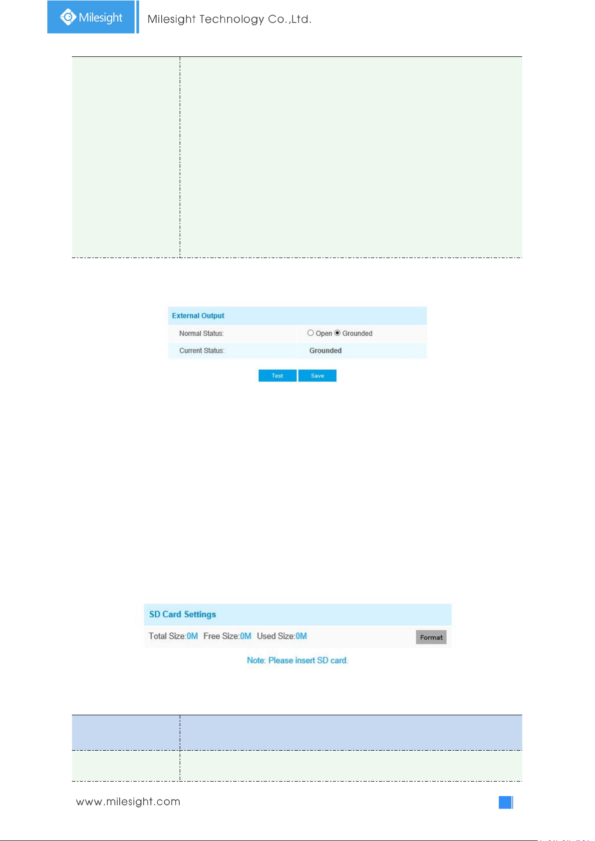
External Output
Parameters
Function Introduction
Format
Format SD card, the files in SD card will be removed
Please set the Normal Status firstly, when the Current Status is different with Normal Status, it will
lead to the alarm.
4.5.2 Storage
Before you start:
To configure record settings, please make sure that you have the network storage device within the
network or the SD card inserted in your camera.
Choose the storage mode according to your needs.
Storage Management
SD Card:
Table 4-5-5 Description of the buttons
Page 76
71
Mount/UnMount
Mount/Dismount SD card
Delete
Enable cyclic storage, when the free disk space reach at a certain value, it will
automatically delete the files at certain percentage according to your settings
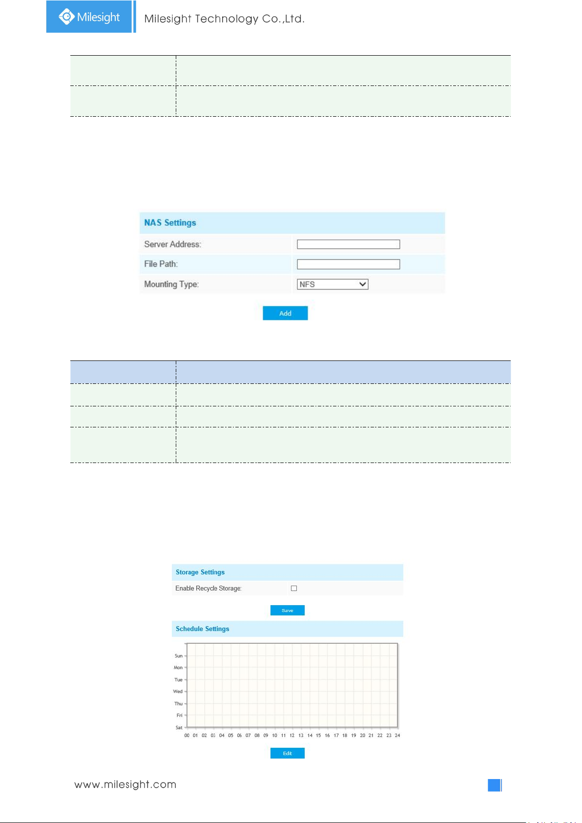
NAS
Parameters
Function Introduction
Server Address
IP address of NAS server
File Path
Input the NAS file path, e.g. “\path”.
Mounting Type
NFS and SMB/CIFS are available. And you can set the user name and password to
guarantee the security if SMB/CIFS is selected
The network disk should be available within the network and properly configured to store the
recorded files, etc.
NAS (Network-Attached Storage), connecting the storage devices to the existing network, provides
data and files services.
Table 4-5-6 Description of the buttons
Note:
Up to 5 NAS disks can be connected to the camera.
Record Settings
Page 77
72
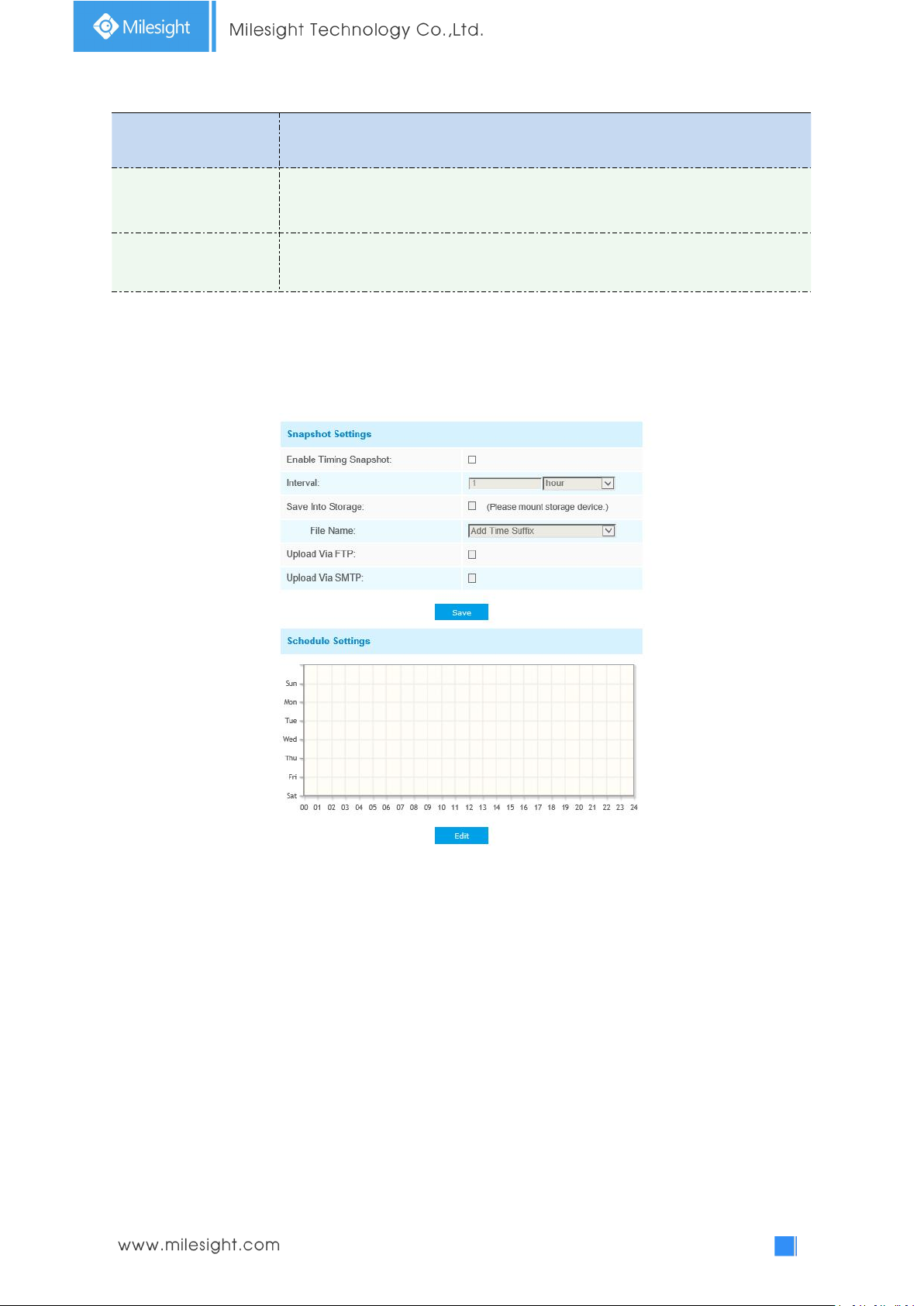
Parameters
Function Introduction
Enable Recycle Storage
Enable/Disable Recycle Storage, if you enable this option, it will delete the files
when the free disk space reach a certain value.
Schedule Settings
Click the Edit button to edit record schedule
Note:
SD Card or NAS are available.
Snapshot Settings
Table 4-5-7 Description of the buttons
Page 78
73
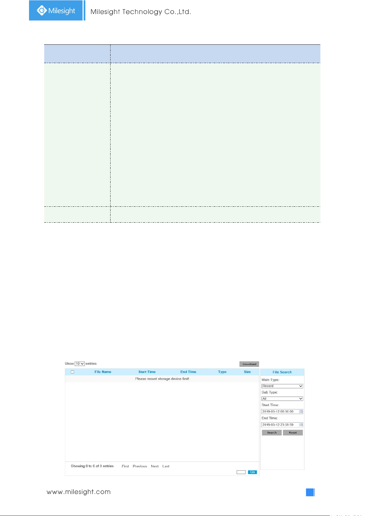
Table 4-5-8 Description of the buttons
Parameters
Function Introduction
Snapshot Settings
Enable Time Snapshot: Check the checkbox to enable the Timing Snapshot
function
Interval: Set the snapshots interval, input the number and choose the
unit(millisecond, second, minute, hour, day)
Save Into Storage: Save the snapshots into SD card or NAS, and choose the file
name to add time suffix or overwrite the base file name.
Save Into NAS: Save the snapshots into NAS, and choose the file name to add
time suffix or overwrite the base file name
Upload Via FTP: Upload the snapshots via FTP
Upload Via SMTP: Upload the snapshots via SMTP
Please note:
If you choose to add time suffix, every snapshot picture will be saved, but if you
choose to overwrite the base file name, only one latest picture will be saved.
When you choose add overwrite the base file name to SD Card or NAS, it will
create a file named “Snapshot” to place the snapshot.
Schedule Settings
Click the Edit button to edit record schedule
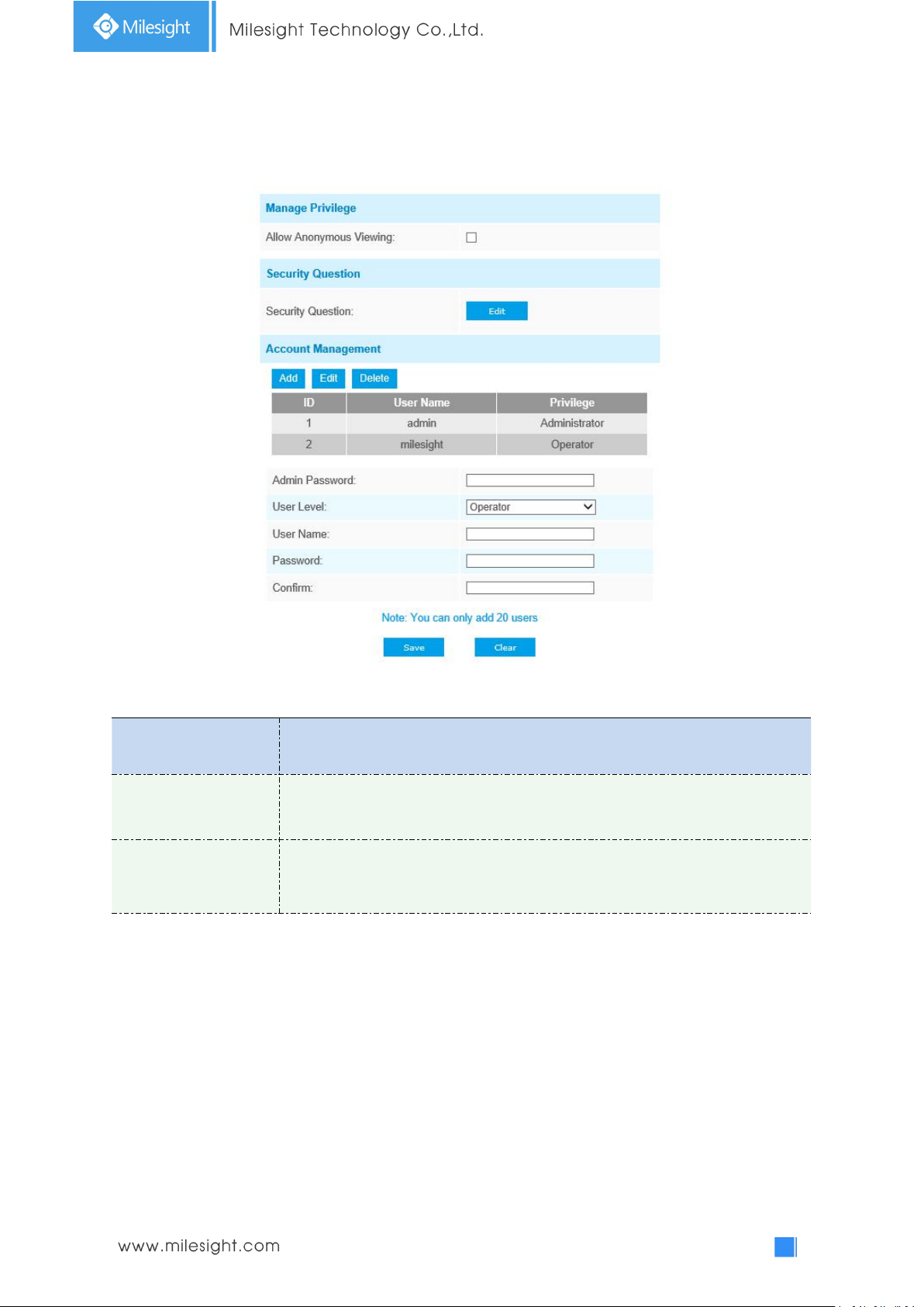
Explorer
Files will be seen on this page when they are configured to save into SD card or NAS.
You can set time schedule every day for recording videos and save video files to your desired
location.
(Note: Files are visible once SD card is inserted. Don’t insert or pull out SD card when power on.)
Video files are arranged by date. Set file type and start/end time to search out files. Each day files
will be displayed under the corresponding date, from here you can copy and delete files etc. You
can visit the files in SD card by ftp, for example, ftp://username:[email protected](user
name and password are the same as the camera account and the IP followed is the IP of your
device.).
Page 79
74
4.5.3 Security
Parameters
Function Introduction
Manage Privilege
Allow anonymous viewing: Check the checkbox to enable visit from whom
doesn’t have account of the device
Security Question
Click “Edit” button to set three security questions for your camera. In case that
you forget the password, you can click “Forget Password” button on login page to
reset the password by answering three security questions correctly.
User
Table 4-5-9 Description of the buttons
Page 80
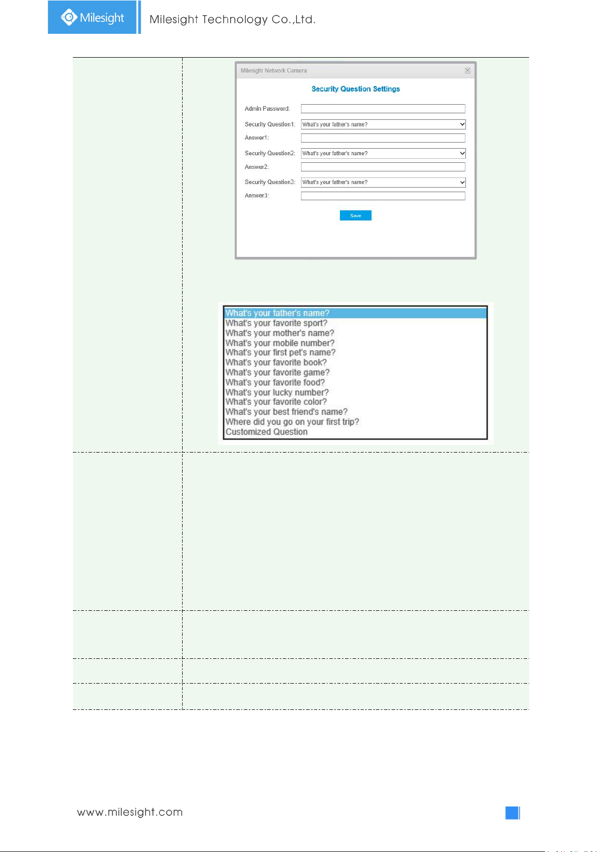
75
There are twelve default questions below, you can also customize the security
questions.
Account Management
Click “Add” button, it will display Account Management page. You can add an
account to the camera by entering the following information. The added account
will be displayed in the account list. You can edit and delete the account in the
account list (except the admin account).
Admin Password: You can only add an account after you enter the correct admin
password.
User Level: Set the privilege for the account.
User Name: Input user name for creating an account
Password: Input password for the account
Confirm: Confirm the password
Administrator
An administrator can manage all configuration pages of the device, including
change user password, add or delete users (the default user “admin” cannot be
deleted)
Operator
An operator can manage all configuration pages except the User page
Viewer
A viewer can`t change any settings
Note:
1) For versions above 54, the Operator and Viewer users are closed by default. But you still
can add on the User page.
2) You can only add 20 users.
Page 81
76
3) For V4x.7.0.69 or above, it removes the default admin password and allows to set a
Parameters
Function Introduction
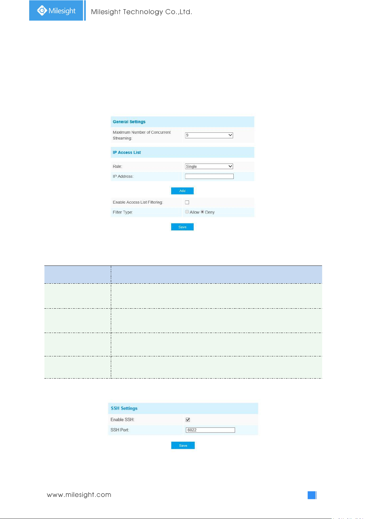
General Settings
Maximum number of concurrent streaming: Select the maximum number of
concurrent streaming. Options include No Limit, 1~9
IP access list
Rule: Single, Network and Range are available
IP address: Input the address to get the access to the device
Enable access list
filtering
Able to access or restrict access for some IP address
Filter type
Access or restrict access
password when logging in for the first time. It also supports set-up of the security questions for the
devices. Users can reset the password by answering the correct security questions in case of
forgetting the password, which is more convenient for users.
Access List
Security Service
Table 4-5-10 Description of the buttons
Page 82
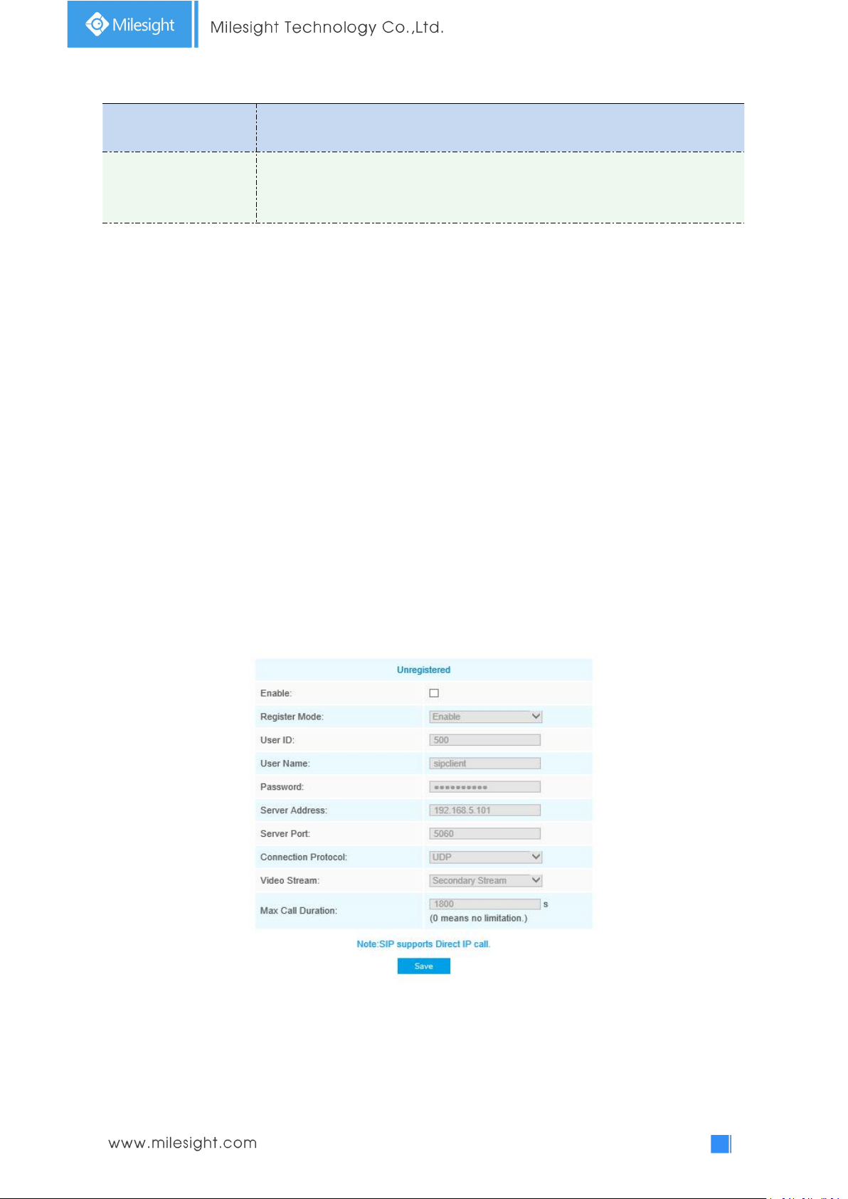
77
Table 4-5-11 Description of the buttons
Parameters
Function Introduction
SSH Settings
Secure Shell (SSH) has many functions: it can replace Telnet and also provides a
secure channel for FTP, POP, even for PPP.
4.5.4 SIP
The Session Initiation Protocol(SIP) is a signaling communications protocol, widely used for
controlling multimedia communication sessions such as voice and video calls over Internet
Protocol(IP) networks. This page allows user to configure SIP related parameters. Milesight
cameras can be configured as SIP endpoint to call out when alarm triggered; or allow permitted
number to call in to check the video if the video IP phone is used. To use this function, the settings
in SIP page must be configured properly. There are two ways to get video through SIP, one is to dial the
IP address directly, the other is account registration mode, the details are as follows:
Method 1: IP Direct mode
Dial on the camera’s IP address directly through SIP phone, so you can see the video.
(Note: SIP phone and the camera should in the same network segment).
Method2: Account registration mode
1) Before using the SIP, you need to register an account for the camera from the SIP server;
2) Register another user account for the SIP device from the same SIP server;
3) Call the camera User ID from the SIP device, you will get the video on the SIP device.
SIP Settings
Page 83
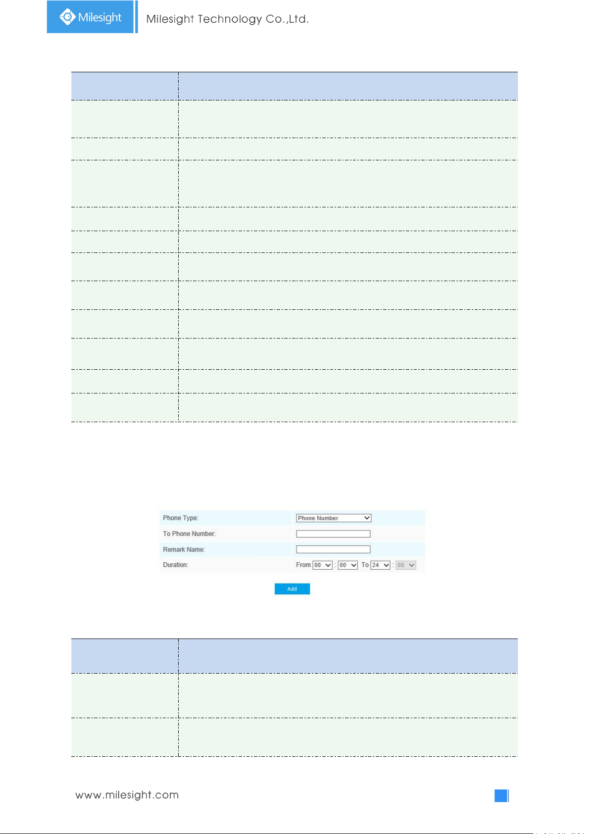
78
Table 4-5-12 Description of the buttons
Parameters
Function Introduction
Unregistered/
Registered
SIP registration status. Display “Unregistered” or “Registered”
Enable
Start or stop using SIP
Register Mode
Choose to use Enable mode or Disable mode. Enable mode means to use SIP with
register account. Disable mode refers to use SIP without register account, just use
the IP address to call.
User ID
SIP ID
User Name
SIP account name
Password
SIP account password
Server Address
Server IP address
Server Port
Server port
Connection
Protocol
UDP/TCP
Video Stream
Choose the video stream
Max Call Duration
The max call duration when use SIP
Parameters
Function Introduction
Phone Type
Phone Number(Call by phone number) & Direct IP Call(Check to accept peer to
peer IP call).
To Phone Number/
IP Address
Call by phone number or IP address.
Note: SIP supports Directly IP call.
Alarm Phone List
Table 4-5-13 Description of the buttons
Page 84
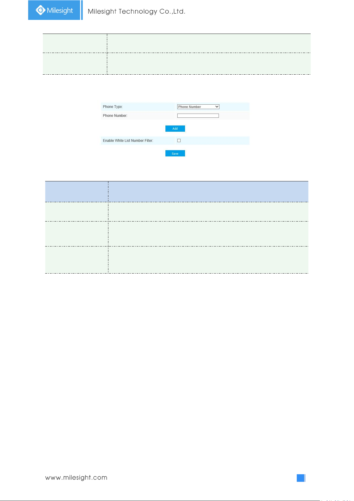
79
Remark Name
Display name.
Duration
The time schedule to use SIP.
White List
Parameters
Function Introduction
Phone Type
Phone Number(Call by phone number) & Direct IP Call
Phone Number/
IP Address
Including the phone number or IP address on the white list
Enable White List
Number Filter
When enabled, only the designated phone number or IP address can visit
Table 4-5-14 Description of the buttons
4.5.5 Smart Event
Smart Event uses Milesight Video Content Analysis technology. This technical capability is used in a
wide range of domains including entertainment, health-care, retail, automotive, transport, home
automation, safety and security. Milesight VCA provides advanced, accurate smart video analysis
for Milesight network cameras. It enhances the performance of network cameras through 10
detection modes which are divided into basic function and advanced function, enabling the
comprehensive surveillance function and quicker response of cameras to different monitoring
scenes.
Region Entrance
Region entrance helps to protect a special area from potential threat of suspicious person’s or
object’s entrance. An alarm will be triggered when objects enter the selected regions by enabling
region entrance.
Page 85
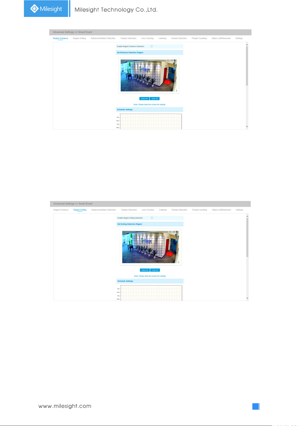
80
Step1: Set entrance detection region;
Step2: Set detection schedule;
Step3: Set alarm action;
Step4: Set alarm settings.
Region Exiting
Region exiting is to make sure that any person or object won't exit the area that is being monitored.
Any exit of people or objects will trigger an alarm.
Step1: Set exiting detection region;
Step2: Set detection schedule;
Step3: Set alarm action;
Step4: Set alarm settings.
Advanced Motion Detection
Different from traditional motion detection, Milesight advanced motion detection can filter out
“noise” such as lighting changes, natural tree movements, etc. When an object moves in the
selected area, it will trigger alarm.
Page 86
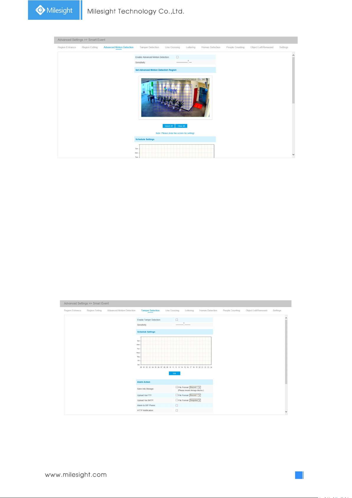
81
Step1: Set detecting sensitivity;
Step2: Set advanced motion detection region;
Step3: Set detection schedule;
Step4: Set alarm action;
Step5: Set alarm settings.
Note:
The sensitivity can be configured to detect various movement according to different requirements.
When the level of sensitivity is low, slight movement won’t trigger the alarm.
Tamper Detection
Tamper Detection is used to detect possible tampering like the camera being unfocused,
obstructed or moved. This functionality alerts security staff immediately when any
above-mentioned actions occur.
Step1: Set detecting sensitivity;
Step2: Set detection schedule;
Step3: Set alarm action;
Step4: Set alarm settings.
Page 87
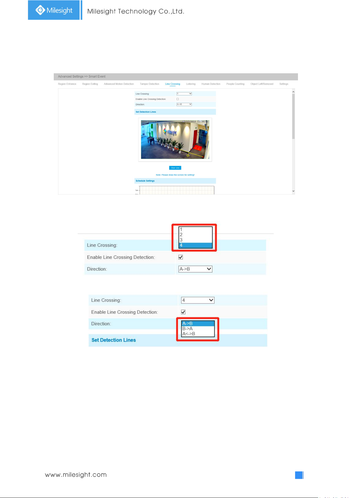
82
Line Crossing
Line Crossing detection is designed to work in most indoor and outdoor environment. An event will
be triggered every time when the camera detects objects crossing a defined virtual line.
Settings steps are shown as follows:
Step1: Choose a line number;
Step2: Enable Line Crossing Detection and define its direction;
Step3: Draw detection lines;
Step4: Set detection schedule;
Step5: Set alarm action;
Step6: Set alarm settings.
Note:
Milesight allows to set up to four lines at a time. There are three direction modes to choose for
triggering alarm. “A→B” means when there is any object crossing the line from the “A” side to the
“B” side, the alarm will be triggered. “B→A” vice versa. “A ↔ B” means that the alarm will be
triggered when objects cross line from either side.
Page 88
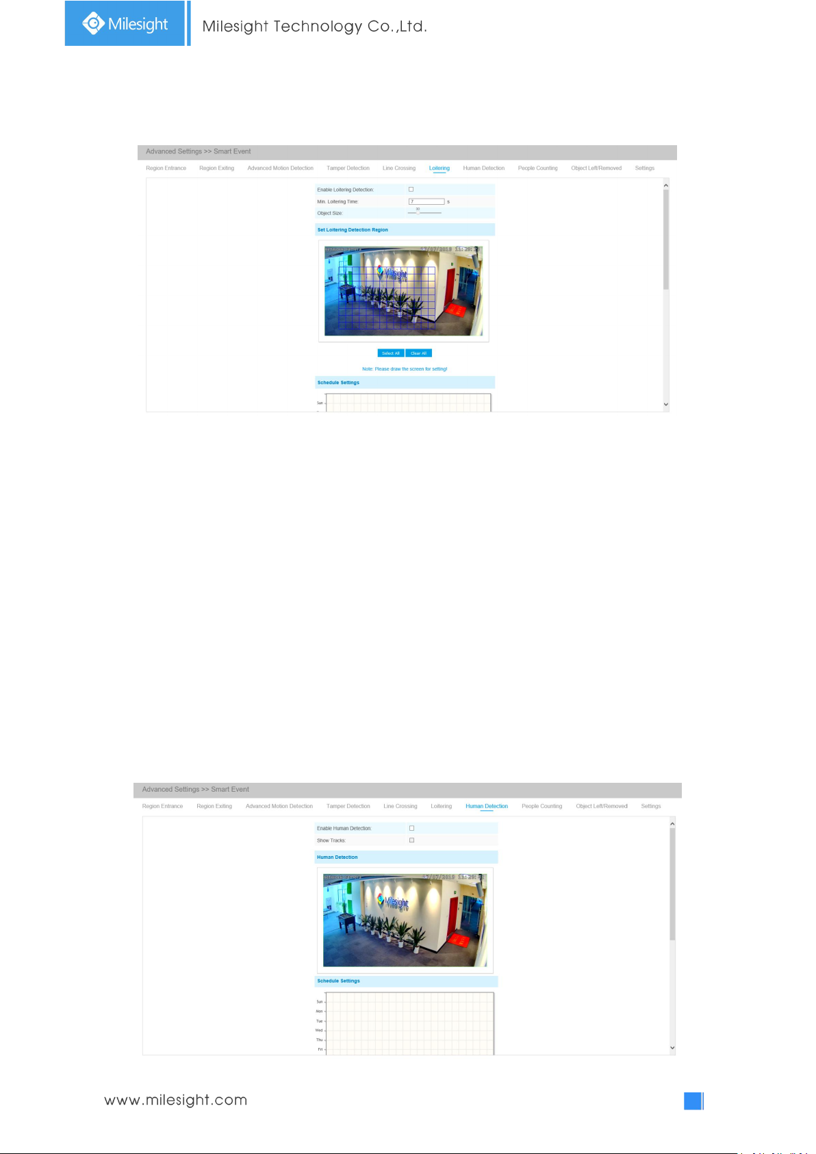
83
Loitering
When objects are loitering in a defined area for a specific period of time, it would trigger an alarm.
Step1: Set minimum loitering time;
Step2: Set object size;
Step3: Set loitering detection region;
Step4: Set detection schedule;
Step5: Set alarm action;
Step6: Set alarm settings.
Note:
After setting minimum loitering time from 3s to 1800s, any objects loitering in the selected area
over the minimum loitering time will trigger the alarm. Also Milesight loitering allows to set
“Object Size”. Only the object bigger than the set size will trigger the alarm.
Human Detection
Human detection is used for figuring out whether an object is a human or not. Once human
detection is enabled, when there is an object appearing in the detecting area, an ID will show on
the frame. If the object is a person, it will mark as “person”. When the Show Tracks is enabled, the
tracks of the moving object will show on the screen.
Page 89
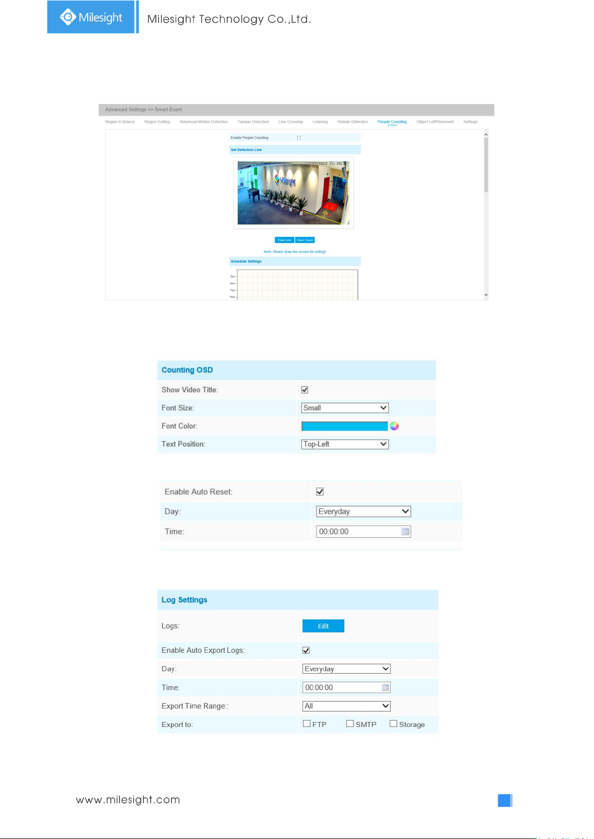
84
People Counting
People counting is able to count that how many people enter or exit during the setting period.
Step1: Set detection line;
Step2: Set detection schedule;
Step3: Set counting OSD;
The OSD of the people counting support automatic zeroing;
Step4: Click “Edit” to check the counting logs, the data log can be exported to FTP/ SMTP/ Storage
automatically as an Excel spreadsheet according to the time interval and range you set;
Step5: Set alarm trigger. Alarm will be triggered when the thresholds reaches to a certain value
Page 90
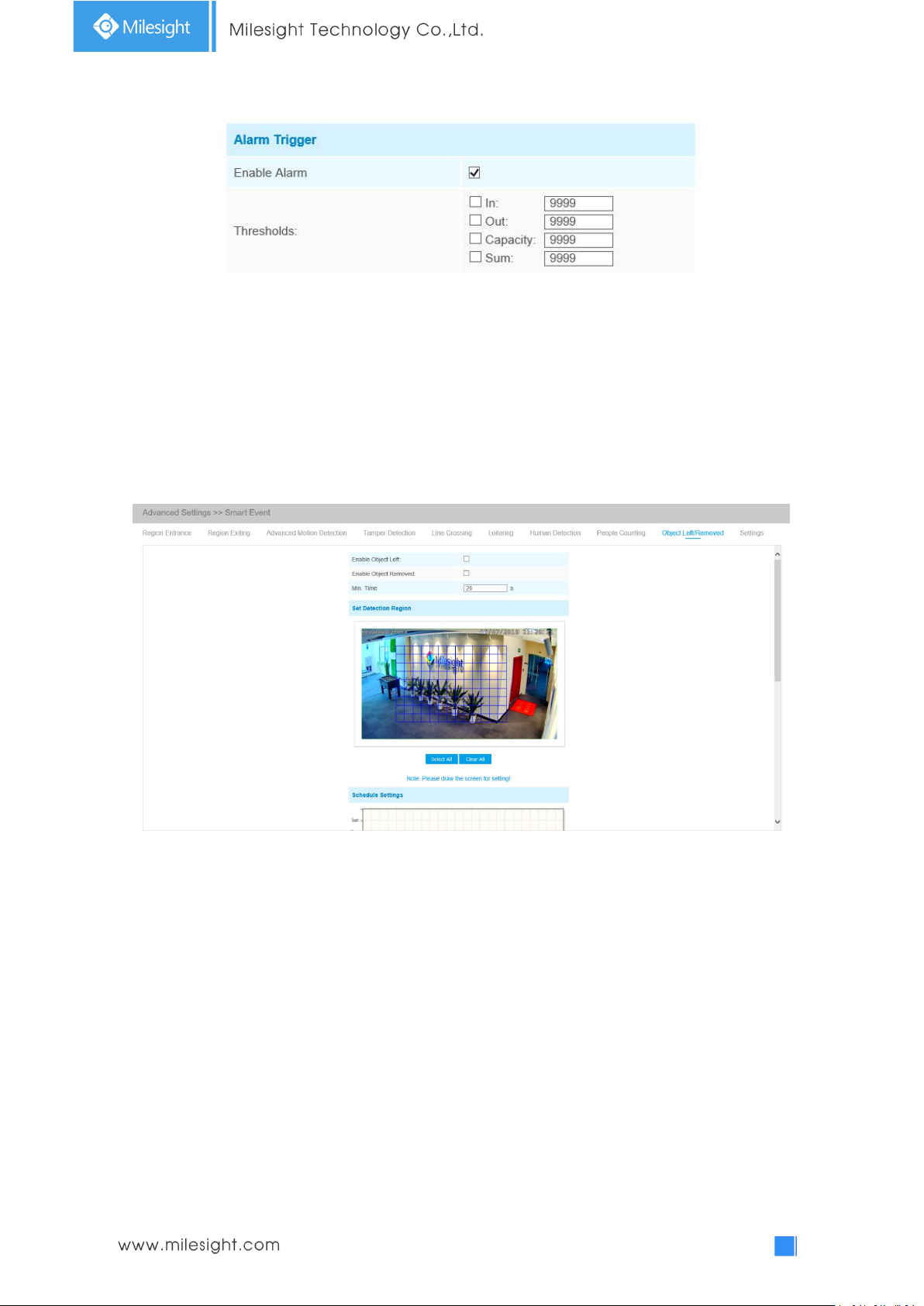
85
from 1 to 9999.
Step6: Set alarm action;
Step7: Set alarm settings.
Note:
Crossing along the direction of the arrow will record as “In”, opposite is “Out”;
Object Left/Removed(Optional)
Object Left can detect and prompt an alarm if an object is left in a pre-defined region. Object
Removed can detect and prompt an alarm if an object is removed from a pre-defined region.
Step1: Enable Object Left or Object Removed(Or you can enable both features at the same time);
Step2: Set minimum time;
Step3: Set detection region;
Step4: Set detection schedule;
Step5: Set alarm action;
Step6: Set alarm settings.
Note:
1. After setting minimum time from 3s to 1800s, any objects are left in the selected area or
removed from the selected area over the minimum time will trigger the alarm.
2. Object Left/Removed is optional, if you need this function, please contact Milesight sales first.
Settings
Milesight VCA provides the primary setting for the whole VCA functions. “Minimum Size” is to set
the whether an object is big enough to trigger other settings. The frame you draw on the screen
Page 91
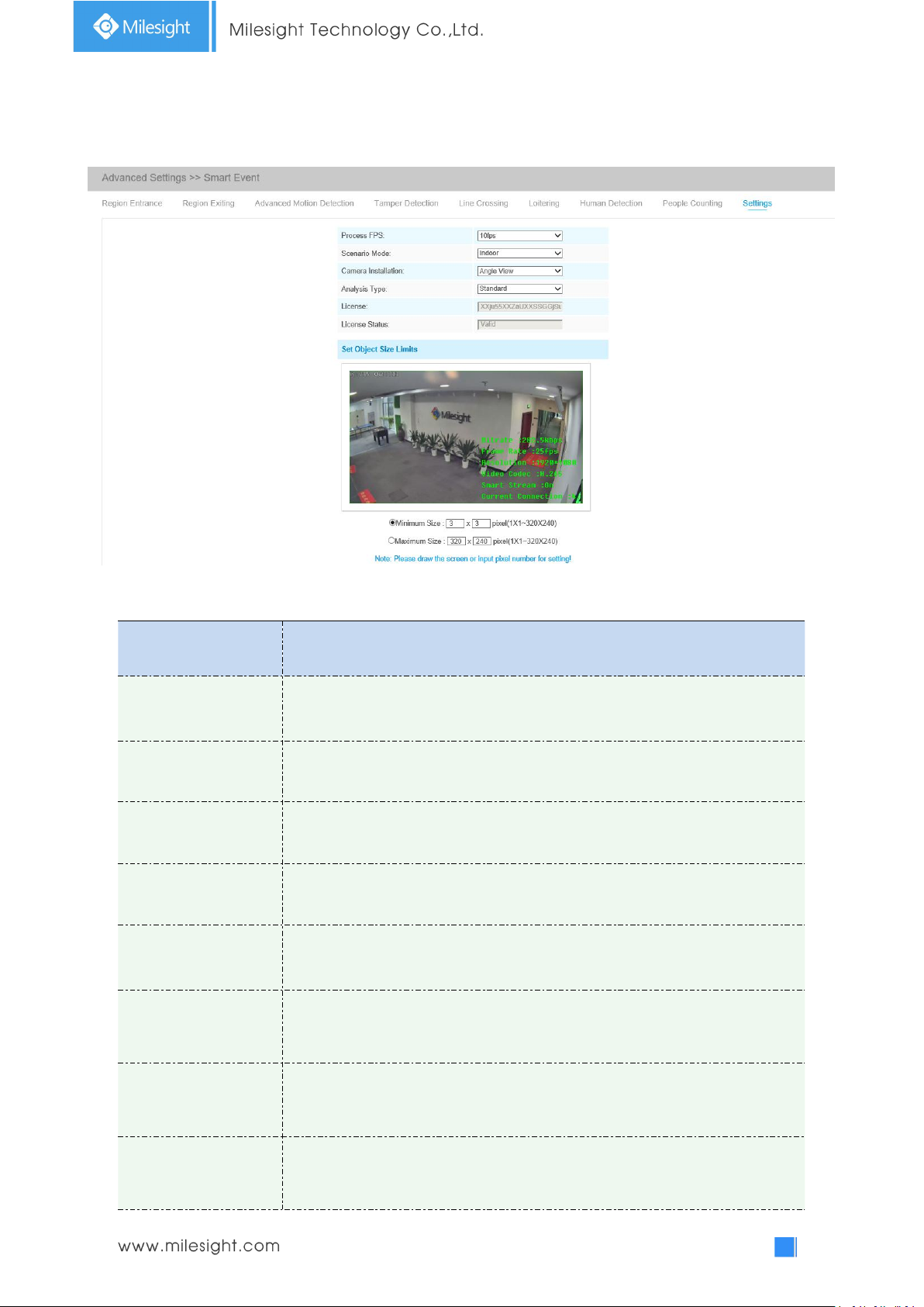
86
means that only if the object size is bigger than the frame, the settings for other VCA functions will
Parameters
Function Introduction
Process FPS
Five different periods are available(5, 10, 15, 20, 25, fps) for process fps
Scenario Mode
Select Indoor or Outdoor mode to meet your needs
Camera Installation
Select camera installation view, including Angle View, Horizontal View and
Overhead View
Analysis Type
Select Standard or Advanced analysis type
License
Generated by camera’s information
License Status
Show present license status, including Valid, Invalid, Expired, Unactivated
Minimum Size
Draw the screen or input pixel number to set the minimum size of the
detected object. When the object is smaller than this size, it will not be
detected. The default minimum size is 1*1.
Maximum Size
Draw the screen or input pixel number to set the maximum size of the
detected object. When the object is larger than this size, it will not be
detected. The default maximum size is 320*240.
take effect. Maximum Size means opposite, the frame you draw on the screen stands for that only
if the object size is smaller than the frame, the settings for other VCA functions will take effect.
Table 4-5-15 Description of the buttons
Page 92
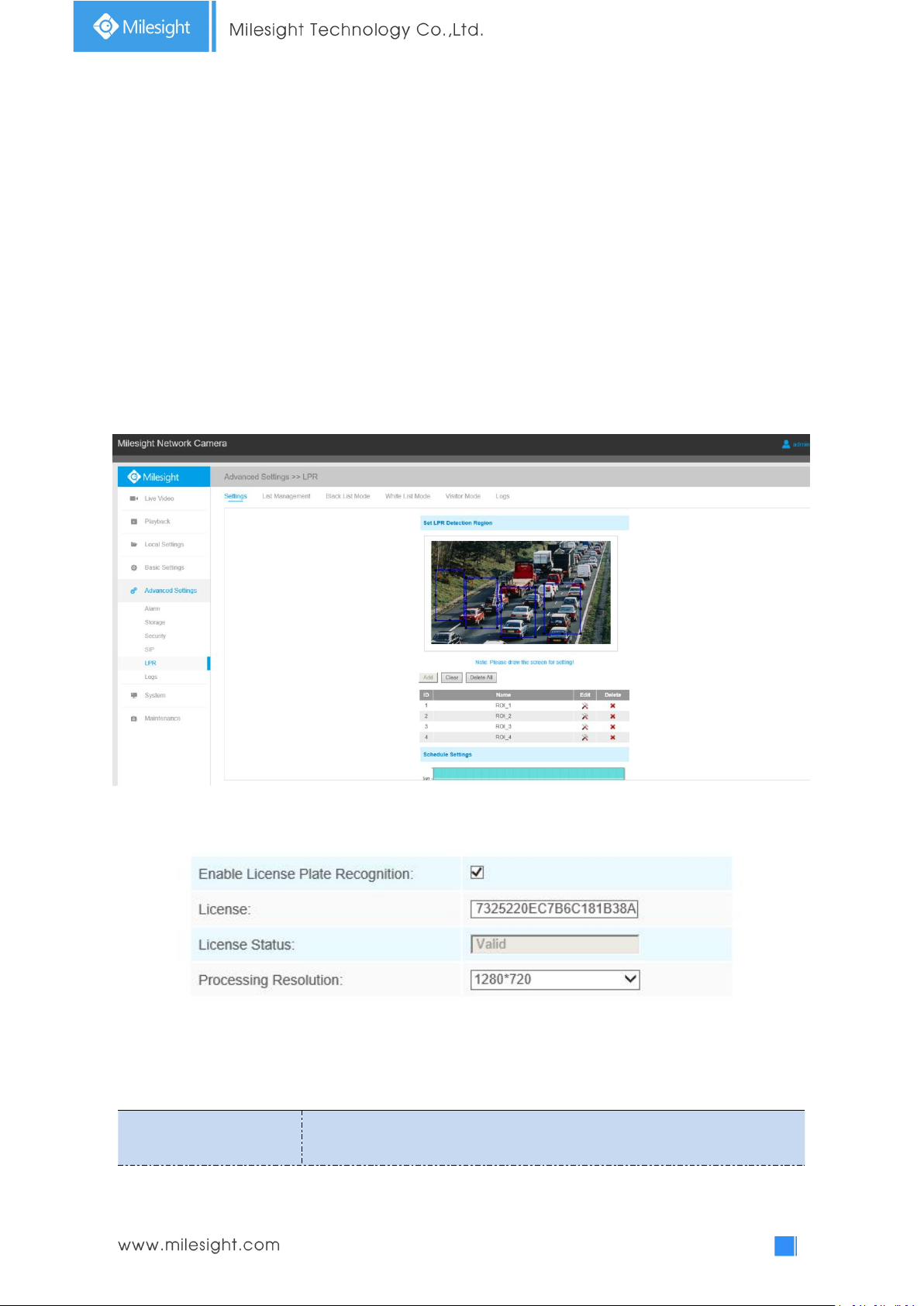
87
4.5.6 LPR(Optional)
Parameters
Function Introduction
The LPR function will automatically detects and captures license plate in real time and compares to
a predefined list, then takes appropriate action such as generating an alert once the license plate is
on the predefined black list.
Note:
(1) LPR is optional for 12x AF Motorized Pro Bullet, Mini PoE PTZ Bullet, ABF Pro Box, Vandal-proof
Motorized Mini Bullet, Motorized Pro Bullet Network Camera.
(2) Currently we have three LPR versions, LPR1, LPR2 and LPR3. LPR1 is for Asian regions, LPR2 is
for European regions and the former Soviet Union and LPR3 is for Korea.
For more information, please refer to Milesight-Troubleshooting-LPR setting-LPR1,
Milesight-Troubleshooting-LPR setting-LPR2, Milesight-Troubleshooting-LPR setting-Korea.
Settings
Step1: Enter the license and click Save. When the License Status changes to Valid, the camera can
start detecting the license plate.
Note: Only LPR2 and LPR3 need to enter a license to activate the LPR function.
Step2: Check the checkbox “Enable License Plate Recognition”, you can draw the screen to select
area interested.
Table 4-5-16 Description of the buttons
Page 93
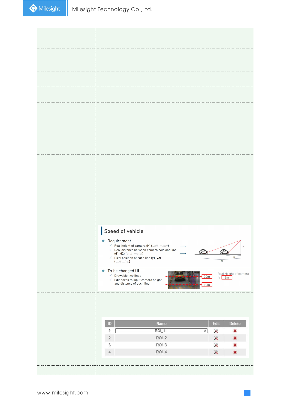
88
License
(Only for LPR2 and LPR3)
Generated by camera’s information
License Status
(Only for LPR2 and LPR3)
Show present license status, including Valid, Invalid.
Processing Resolution
Resolution of the stream for LPR analysis, including 1920*1280, 1280*720,
640*360, 320*176.
Country/ Region
(Only for LPR1)
Select country/ region to detect the license plate.
Effective Region Settings
(Only for PTZ series)
Normal: configure the LPR detection regions for the current area.
Advanced: configure different LPR detection regions for different PTZ
presets(Only support Preset 1~4 so far).
Enable Day/Night
Detection Mode
(Only for LPR3)
With this option enabled, the camera will enable different detection modes
according to Day/Night mode.
Enable Vehicle Speed
Detection
(Only for LPR3)
With this option enabled, the camera will detect the vehicle speed and
display the result on the logs interface.
You need to draw two lines(Line1 and Line2) on the live view, and fill in
Camera Installation Height, Horizontal Distance1 and Horizontal Distance2,
camera will combine the line you draw and the data filled to calculate the
vehicle speed.
Camera Installation Height: real height of camera.
Horizontal Distance1: real distance between camera pole and line1.
Horizontal Distance2: real distance between camera pole and line2.
Add
Draw the screen to select the area interested, then click “Add”button to add
the area,only four recognition areas can be added.
You can edit the name of the area or delete the area in the list below.
Note: Only license plates larger than 150 pixels can be recognized.
Clear
Click the "Clear" button to clear the area being drawn.
Page 94
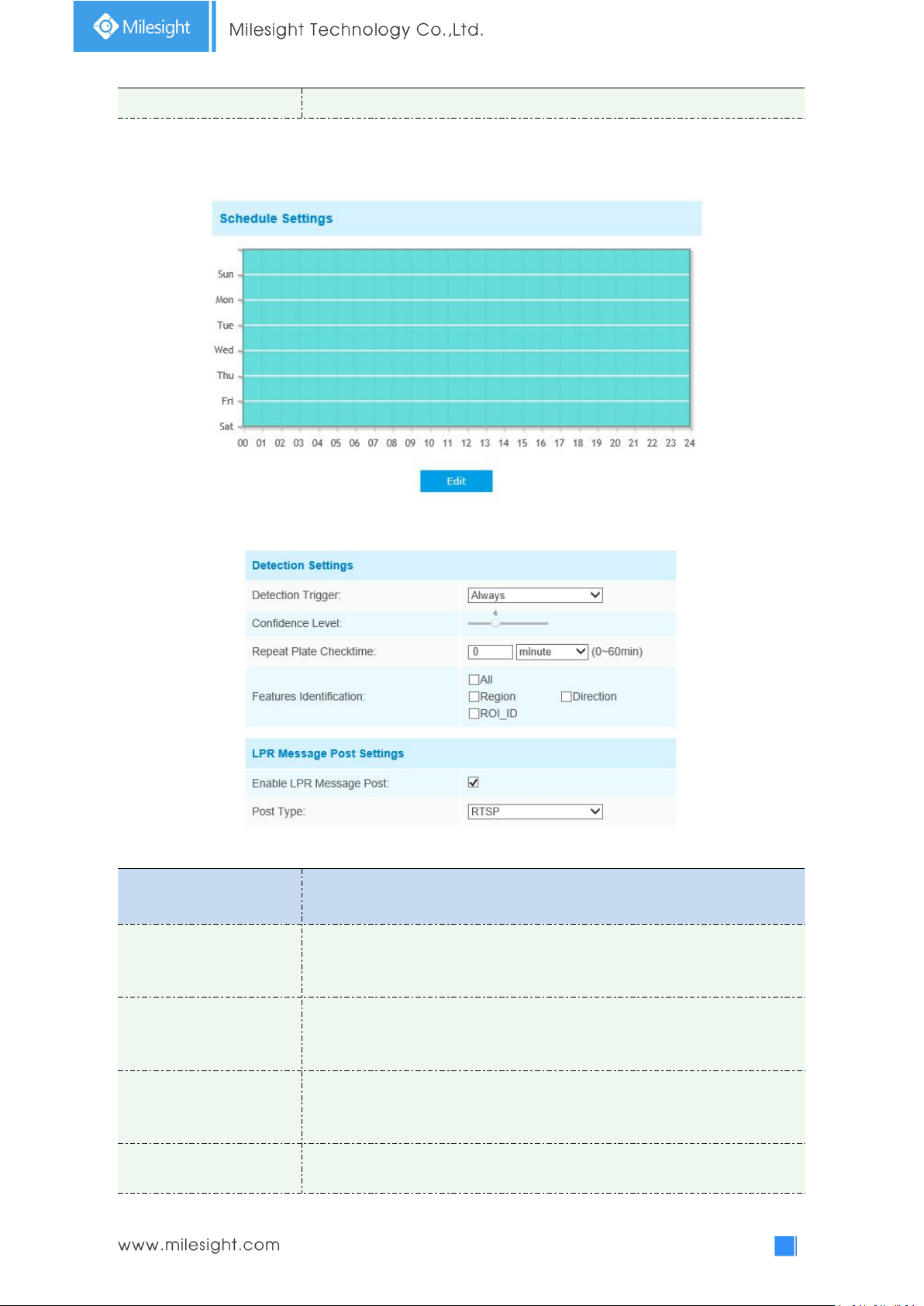
89
Delete All
Click the "Delete All" button to delete all the added areas.
Step3: Schedule Settings. You can draw the schedule by clicking Edit button.
Parameters
Function Introduction
Detection Trigger
Always: in this mode, camera will always detect the license plate.
Alarm Input: in this mode, camera will only detect the license plate during
Alarm Input is being triggered.
Confidence Level
(Only for LPR1 and LPR2)
You can set the confidence level from 1 to 10.
When the confidence level of the license plate is higher than the set
confidence level, it will push the license plate image to the logs interface.
Repeat Plate Checktime
Set the time interval for repeatedly reading license plates to effectively avoid
duplicate identification of parking vehicles.
You can set Repeat Plate Checktime from 0 to 60min or 0 to 60000ms.
Feature Identification
Check Region(Only for LPR2), ROI_ID, Direction or All to enable Features
Identification, it will display the corresponding information
Step4: Set Detection Settings and LPR Message Post Settings.
Table 4-5-17 Description of the buttons
Page 95
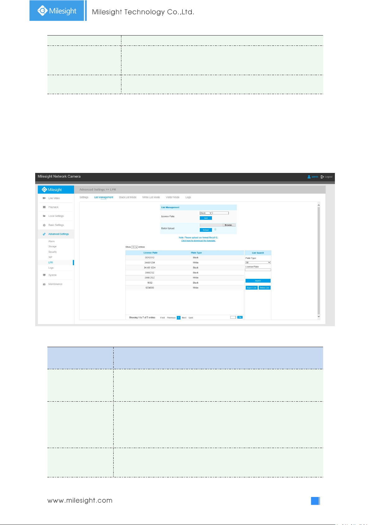
90
on the logs interface.
Enable LPR Message Post
Check the checkbox to enable LPR Message Post. It will push information to
some third-party devices or softwares that are compatible with ours.
Post Type
Information can be pushed by RTSP, TCP or HTTP.
List Management
Parameters
Function Introduction
Add License Plate
Select the license plate type as black or white, enter the license plate, click the
“Add” button, the license plate will be added successfully.
Batch Upload
You can add a csv form with the license plate you want to add, click the
"Browse" button to import the form to this interface, click the "Upload" button,
the license plates will be added successfully.
Note: You can first download the template as a reference in this interface.
List Search
Select Plate Type or directly enter the license plate number, click the “Search”
button, the corresponding license plate will be displayed in the list below.
Add the license plates to this interface as Black or White type (Black/White List), and then you can
set the alarm action for these license plates in the corresponding black list mode or white list
mode interface. When these license plates are detected, the camera will respond accordingly to
your settings.
Table 4-5-18 Description of the buttons
Page 96
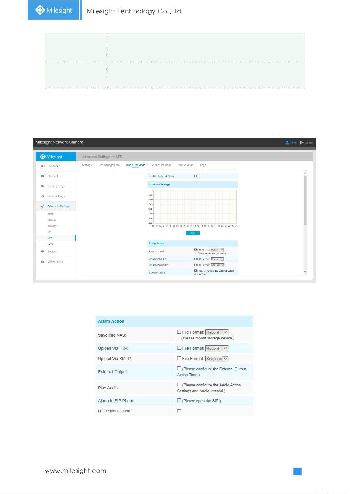
91
Export List
Click the "Export List" button to export the license plate in the current list to a
csv form locally.
Delete List
Click the "Delete List" button to delete all the license plate in the current list.
Note: It supports adding 1000 Black List and White List.
Black List Mode
Step1: Check the checkbox to enable Black List Mode.
Step2: Schedule Settings. You can draw the schedule by clicking Edit button.
Step3: Set alarm action.
Step4: Set alarm settings.
Page 97
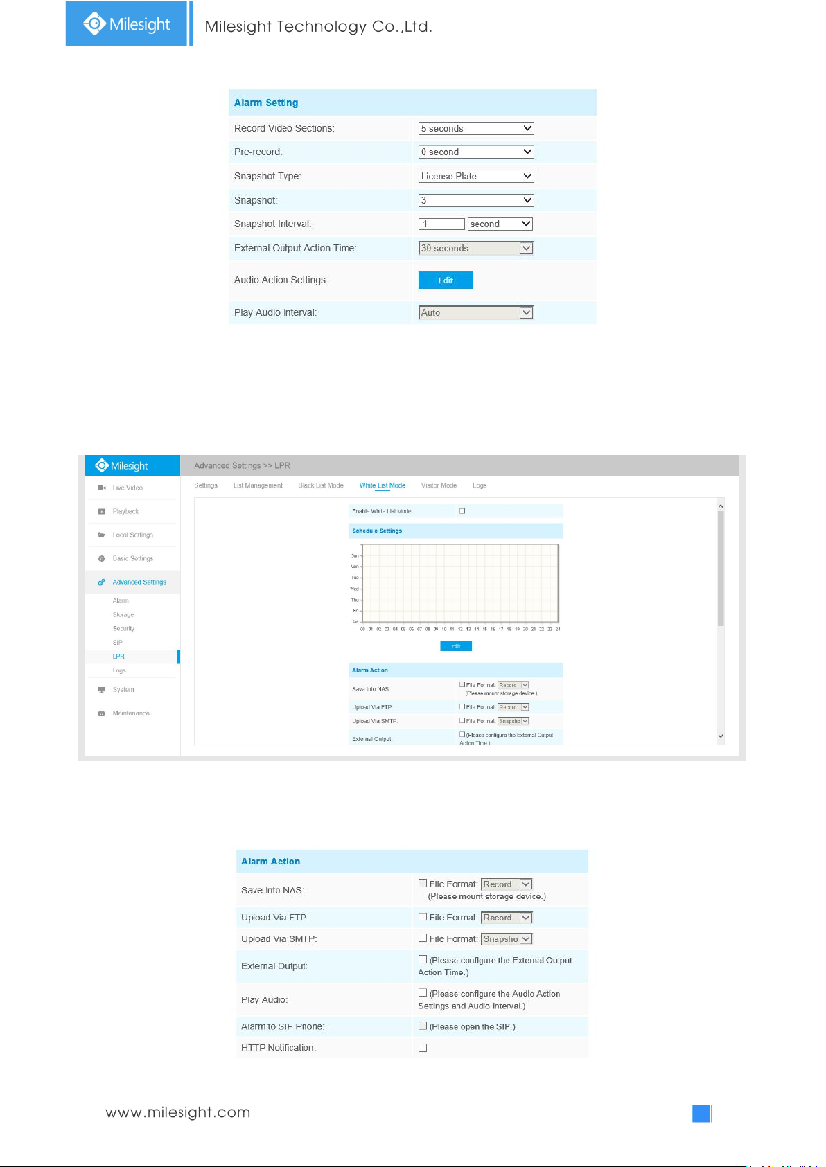
92
After that, when a license plate marked as “black” is detected, the camera will respond accordingly
to your settings.
White List Mode
Step1: Check the checkbox to enable White List Mode.
Step2: Schedule Settings. You can draw the schedule by clicking Edit button.
Step3: Set alarm action.
Page 98
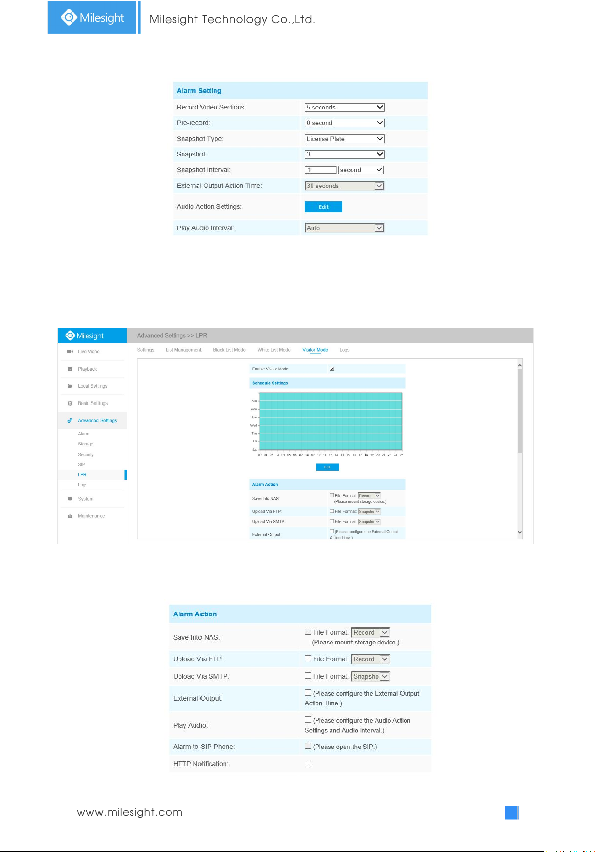
93
Step4: Set alarm settings.
After that, when a license plate marked as “White” is detected, the camera will respond
accordingly to your settings.
Visitor Mode
Step1: Check the checkbox to enable Visitor Mode.
Step2: Schedule Settings. You can draw the schedule by clicking Edit button.
Step3: Set alarm action.
Page 99
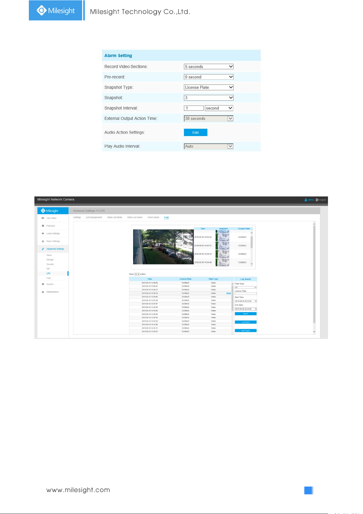
94
Step4: Set alarm settings.
After that, when a license plate that is not marked as "Black" or "White" is detected, the camera
will respond accordingly to your settings.
Logs
The detect results in real time will be displayed on the right side of Logs page, including detected
time, live screenshot, and license plate.
Note: Only 10 logs are visible on the right side.
Page 100
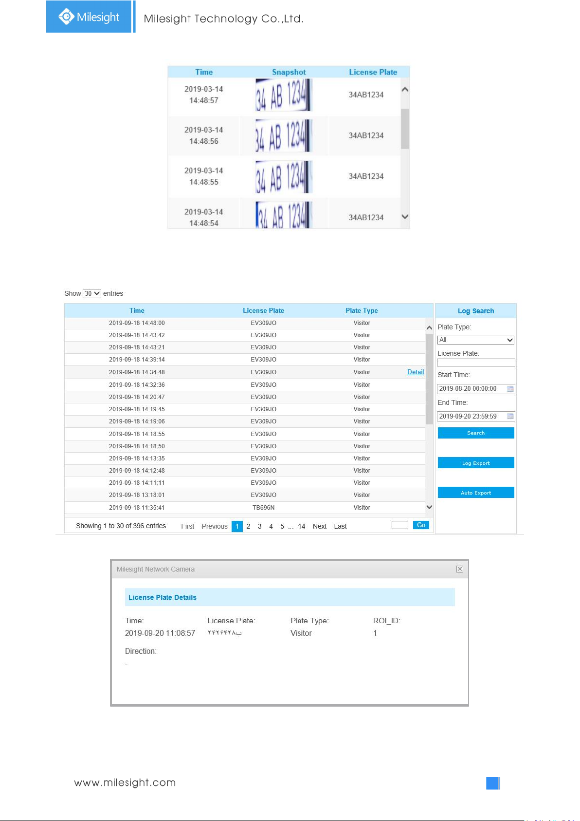
95
Select Plate Type or directly enter the license plate number, select Start Time and End Time, click
the “Search” button, the corresponding license plate will be displayed in the list below.
Note: It supports displaying 10,000 logs.
Click on the "Detail" button to the right of each log to display license plate details as shown below.
LPR1
 Loading...