

Milesight MS-C2942-RB, MS-C3742-B, MS-C5342-B, MS-C4461-EPB, MS-C5361-EPB User Manual
...
PTZ Network Camera
User Manual
V2.04

Thank you for purchasing our product. If there is any question or request, please do not hesitate
to contact your dealer.
This manual is applicable to the Milesight H.265 Network Camera, series are shown as follows,
except where otherwise indicated.
This Manual explains how to use and manage Milesight network cameras on your network.
Previous experience of networking will be of use when using the products. Please read this manual
carefully before operation and retain it for future reference.
This manual may contain several technically incorrect places or printing errors, and the content is
subject to change without notice. The updates will be added into the new version of this manual.
We will readily improve or update the products or procedures described in the manual.
Copyright Statement
This manual may not be reproduced in any form or by any means to create any derivative such as
translation, transformation, or adaptation without the prior written permission of Milesight
Technology Co., Ltd (Hereinafter referred to as Milesight).
Milesight reserves the right to change this manual and the specifications without prior notice. The
latest specifications and user documentation for all Milesight products are available on our official
website www.milesight.com
Industry Canada ICES-003 Compliance:
This Class B digital apparatus complies with Canadian ICES-003.
Cet appareil numerique de la classe B est conforme a la norme NMB-003 du Canada.
Milesight H.265 PTZ Network Camera
Type
Megapixel
2MP
3MP
4MP
5MP
Speed Dome
Network Camera
MS-C2942-(R)B
MS-C3742-B
-
MS-C5342-B
Mini (PoE) PTZ
Bullet Network
Camera
MS-C2961-E(P)B
-
MS-C4461-E(P)B
MS-C5361-E(P)B
Safety Instruction
These instructions are intended to ensure that user can use the product correctly to avoid danger
or property loss. The precaution measures are divided into “Warnings” and “Cautions”
Warnings: Serious injury or death may be caused if any of these warnings is neglected.
Cautions: Injury or equipment damage may be caused if any of these cautions are neglected.
Warnings: Please follow these safeguards to
prevent injury or death.
Cautions: Please follow these safeguards to
prevent potential injury or material damage.
Warnings
This installation must be conducted by a qualified service person and should strictly
comply with the electrical safety regulations of the local region;
To avoid risk of fire and electric shock, do keep the product away from rain and moisture
before installed;
Do not touch components such as heat sinks, power regulators, and processors, which
may be hot;
Source with DC 12V or AC 24V;
Please make sure the plug is firmly inserted into the power socket;
When the product is installed on a wall or ceiling, the device should be firmly fixed;
If the product does not work properly, please contact your dealer. Never attempt to
disassemble the camera by yourself.
Cautions
Make sure that the power supply voltage is correct before using the camera;
Do not store or install the device in extremely hot or cold temperatures, as well as dusty
or damp locations, and do not expose it to high electromagnetic radiation;
Only use components and parts recommended by manufacturer;
Do not drop the camera or subject it to physical shock;
To prevent heat accumulation, do not block air circulation around the camera;
Laser beams may damage image sensors. The surface of image sensors should not be
exposed to where a laser beam equipment is used;
Use a blower to remove dust from the lens cover;
Use a soft, dry cloth to clean the surface of the camera. Stubborn stains can be removed
using a soft cloth dampened with a small quantity of detergent solution, then wipe dry;
Do not use volatile solvents such as alcohol, benzene or thinners as they may damage the
surface finishes;
Save the package to ensure availability of shipping containers for future transportation.
EU Conformity Statement
2012/19/EU (WEEE directive): Products marked with this symbol cannot be disposed
of as unsorted municipal waste in the European Union. For proper recycling, return
this product to your local supplier upon the purchase of equivalent new equipment,
or dispose of it at designated collection points. For more information see:
www.recyclethis.info.
2006/66/EC (battery directive): This product contains a battery that cannot be
disposed of as unsorted municipal waste in the European Union. See the product
documentation for specific battery information. The battery is marked with this
symbol, which may include lettering to indicate cadmium (Cd), lead (Pb), or
mercury(Hg). For proper recycling, return the battery to your supplier or to a designated
collection point. For more information see: www.recyclethis.info.

Table of Contents
Chapter I Product Description
..............................................................................................................
1
1.1 Product Overview
....................................................................................................................
1
1.2 Key Features
............................................................................................................................
1
1.3 Hardware Overview
.................................................................................................................
2
1.4 System Requirements
..............................................................................................................
4
Chapter II Network Connection
............................................................................................................
5
2.1 Setting the Camera over the LAN
............................................................................................
5
2.1.1 Connect the Camera to the PC Directly
.........................................................................
5
2.1.2 Connect via a Switch or a Router
...................................................................................
5
2.2 Dynamic IP Connection
............................................................................................................
5
Chapter III Accessing the Network Camera
..........................................................................................
7
3.1 Assigning An IP Address
...........................................................................................................
7
3.1.1 Assigning An IP Address Using Smart Tools
...................................................................
7
3.1.2 Assign An IP Address via Browser
................................................................................
11
3.2 Accessing from the Web Browser
..........................................................................................
13
3.3 Accessing from Milesight VMS (Video Management Software)
...........................................
15
Chapter IV System Operation Guide
...................................................................................................
16
4.1 Live Video
..............................................................................................................................
16
4.1.1 Operations on Live View Page
.....................................................................................
16
4.1.2 3D Positioning
..............................................................................................................
19
4.1.3 Set / Call a preset / Patrol / Pattern
............................................................................
19
4.2 Playback
.................................................................................................................................
23
4.3 Basic Settings
.........................................................................................................................
25
4.3.1 Video
............................................................................................................................
25
4.3.2 Image
...........................................................................................................................
27
4.3.3 Audio
............................................................................................................................
34
4.3.4 Network
.......................................................................................................................
36
4.3.5 Date&Time
...................................................................................................................
45
4.4 Advanced Settings
.................................................................................................................
46
4.4.1 Alarm
...........................................................................................................................
46
4.4.2 Storage
.........................................................................................................................
54
4.4.3 Security
........................................................................................................................
58
4.4.4 SIP
................................................................................................................................
60
4.4.5 Smart Event
.................................................................................................................
63
4.4.6 PTZ
...............................................................................................................................
70
4.4.7 Logs
..............................................................................................................................
76
4.5 System
....................................................................................................................................
77
4.6 Maintenance
..........................................................................................................................
78
4.6.1 System Maintenance
...................................................................................................
79
4.6.2 Auto Reboot
.................................................................................................................
80
Chapter V Services
..............................................................................................................................
81
1
Chapter I Product Description
1.1 Product Overview
Milesight provides a consistent range of cost-effective and reliable network cameras to fully
meet your requirements. Based on embedded Linux operating system, Milesight network
cameras could be easily accessed and managed either locally or remotely with great reliability.
With built-in high-performance DSP video processing modules, the cameras pride on low power
consumption and high stability. They support state-of-the-art H.265+/ H.265/ H.264+/ H.264/
MJPEG video compression algorithm and industry-leading HD dual-stream technology to achieve
the highest level of video image quality under the limited network resources. It is fully functional,
supporting for flexible and comprehensive alarm linkage mechanism, day and night auto switch,
smart PTZ control and privacy masking, etc.
In practical applications, Milesight network cameras could either work independently in the LAN,
or be networked to form a powerful safety monitoring system. It is widely used in fields such as
finance, education, industrial production, civil defense, health care for security’s sake.
1.2 Key Features
30x AF Lens for Speed Dome, 12x AF Lens for Mini PTZ Bullet
360° continuous pan and 0°~ 90° auto flip tilt for Speed Dome
360° continuous pan and -45°~30° tilt for Mini PTZ Bullet
255 Preset Points and 8 Patrols
Based on Linux OS with high reliability
H.265+/ H.265/ H.264+/ H.264/ MJPEG video compression capability
Support ONVIF Profile S
Support three streams
ICR filter with auto switch, true day/night
Built-in WEB server, support IE/ Firefox/ Chrome/ Safari browser
UPnP protocol for the easy management of IPC
Support Milesight DDNS
3D Positioning, PTZ Motion, PTZ Limit, Scheduled Tasks and Auto Home function
White LED for Mini (PoE) PTZ Bullet
Motion Detection, Privacy Masking, Network Fault Detection and ROI
FTP upload, SMTP upload, SD card record and SIP function
G.711/AAC audio compression capability
Audio Input/Output
Three-privilege levels of users for flexible management
Micro SD/SDHC/SDXC card local storage support, expand the edge storage
Local PAL/NTSC signal output
2
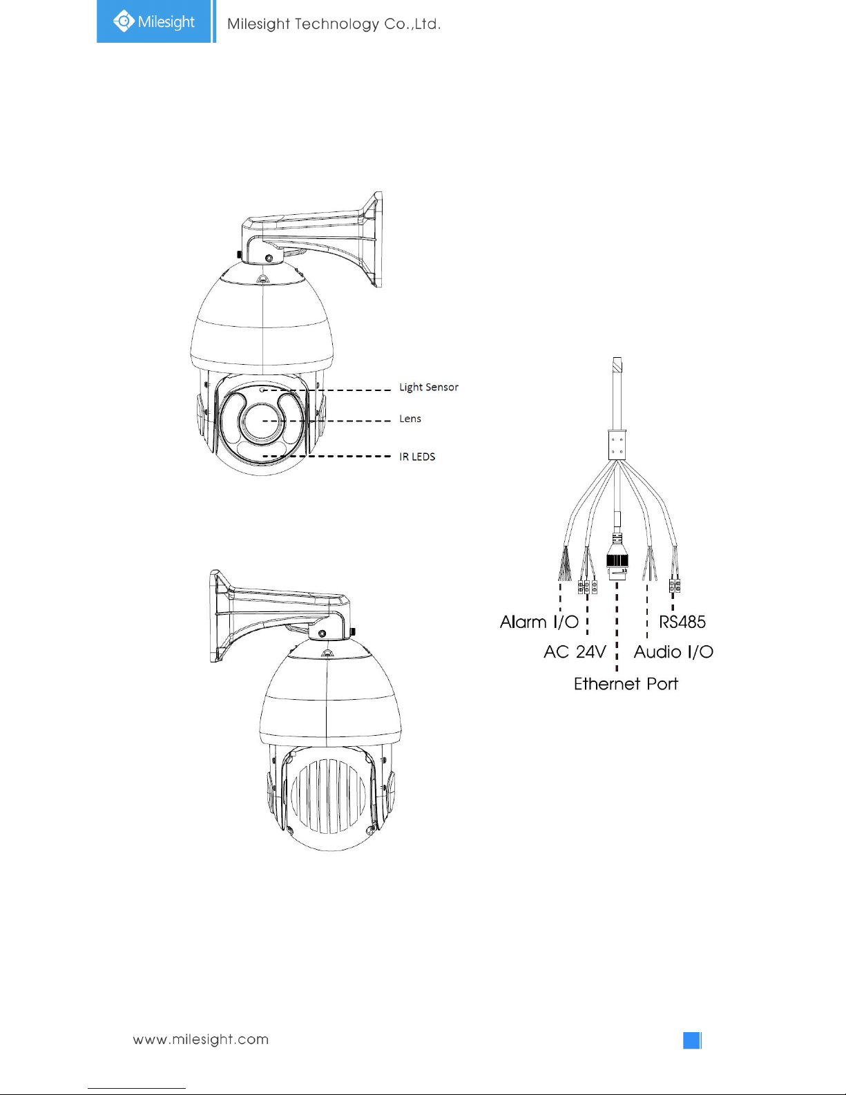
1.3 Hardware Overview
1. Speed Dome Network Camera
Figure 1-3-1 Speed Dome Network Camera
Note:
1) Only AC 24V is available for power supply.
2) Built-in SD card slot can be seen after removing the 4 screws and open the front panel.
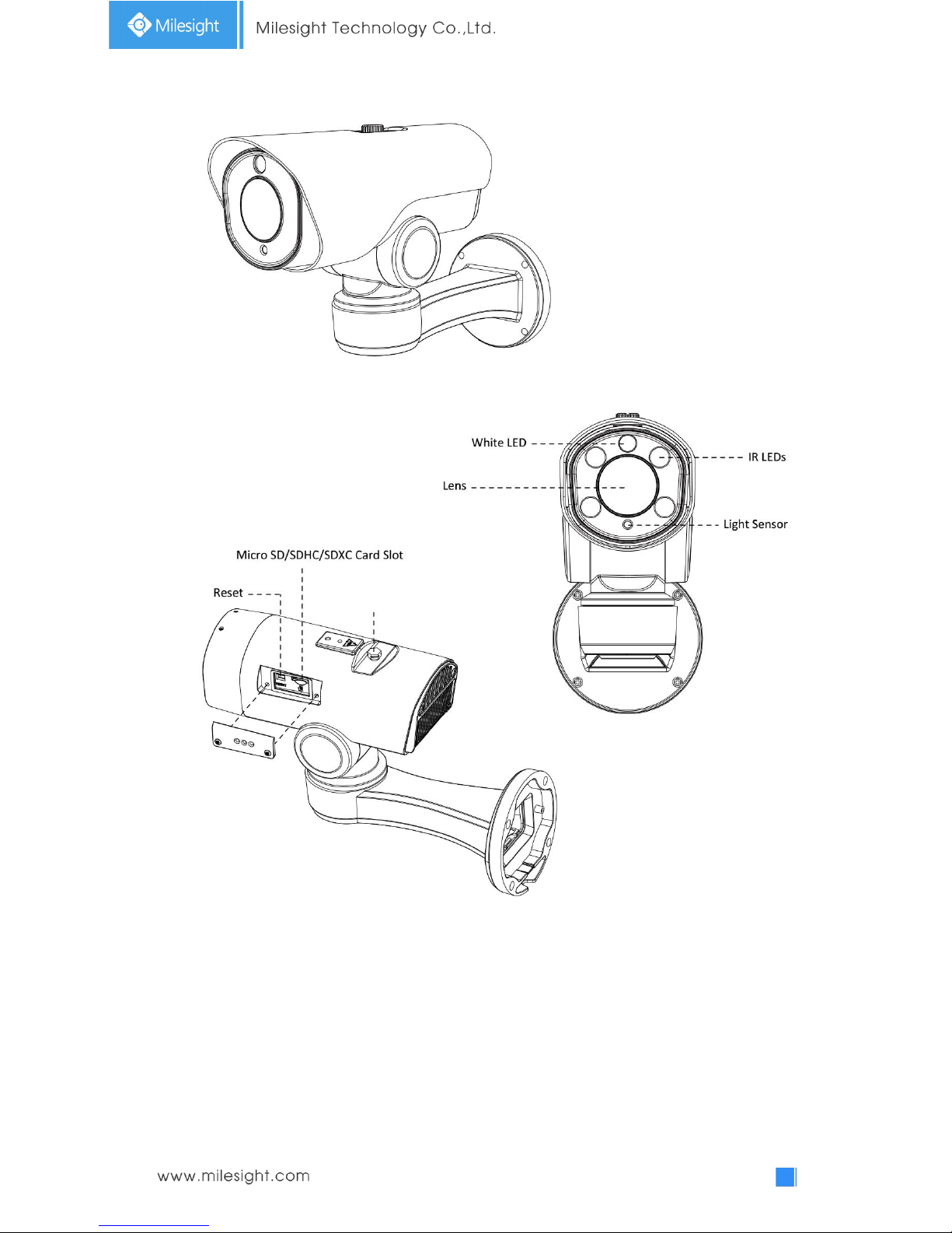
3
2. Mini (PoE) PTZ Bullet Network Camera
Figure 1-3-2 Mini PTZ Bullet Network Camera
Note:
1) DC 12V and PoE are available for power supply.
Screw-in Vent

4
1.4 System Requirements
Operating System: Windows XP/Vista/7/8/10/Server 2000/Server 2008
CPU: 1.66GHz or higher
RAM: 1G or higher
Graphic memory: 128MB or more
Internet protocol: TCP/IP (IPv4/IPv6)
Web Browsers: Internet Explorer 8.0 and above version, Mozilla
Firefox, Google Chrome and Safari.
5
Chapter II Network Connection
2.1 Setting the Camera over the LAN
Connecting the camera to a switch or a router is the most common connection method. The
camera must be assigned an IP address that is compatible with its LAN.
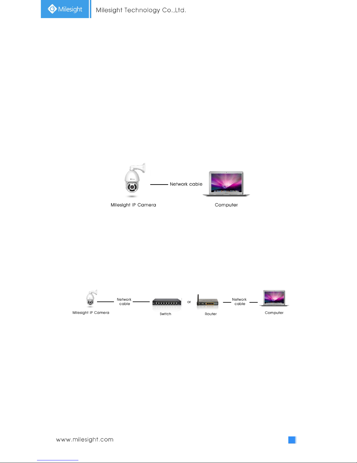
2.1.1 Connect the Camera to the PC Directly
In this method, only when the computer connected to a camera, it will be able to view the camera.
The camera must be assigned a compatible IP address to the computer. Details are shown as the
following figure.
Figure 2-1-1 Connect the camera to the PC directly
2.1.2 Connect via a Switch or a Router
Set network camera over the LAN via the switch or router as figure 2-1-2:
Figure 2-1-2 Connect via a switch or a Router
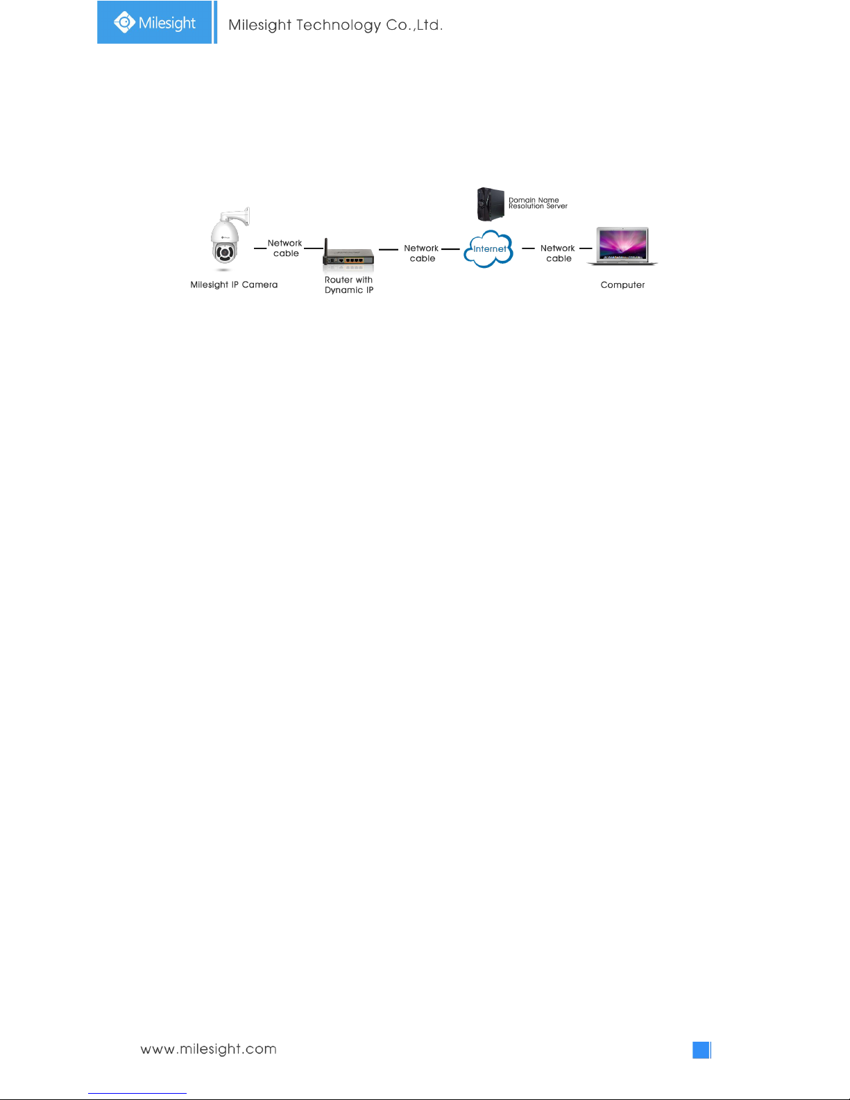
2.2 Dynamic IP Connection
Connecting the network camera via a router
Step1: Connect the network camera to a router;
Step2: On the camera, assign a LAN IP address, a Subnet mask and a Gateway;
Step3: On the router, set port forwarding. E.g. 80, 8000 and 554 ports. The steps for port
forwarding vary depending on different routers. Please look up the router's user manual for
6
assistance with port forwarding;
Step4: Apply a domain name from a domain name provider;
Step5: Configure the DDNS settings in the setting interface of the router;
Step6: Visit the camera via the domain name.
Figure 2-2 Connect the network camera via a router using dynamic IP
7
Chapter III Accessing the Network Camera
The camera must be assigned an IP address to be accessible.
3.1 Assigning An IP Address
The Network Camera must be assigned an IP address to be accessible. The default IP address of
Milesight Network Camera is 192.168.5.190. The default user name is “admin”, and password is
“ms1234”.
You can either change the IP address of the camera via Smart Tools or browser. Please connect the
camera in the same LAN of your computer.
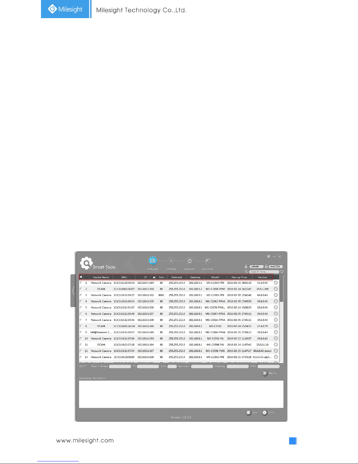
3.1.1 Assigning An IP Address Using Smart Tools
Smart Tools is a software tool which can automatically detect multiple online Milesight network
cameras in the LAN, set IP addresses, and manage firmware upgrades. It’s recommended to use
when assigning IP addresses for multiple cameras.
Step1: Install Smart Tools (The software could be downloaded from our website);
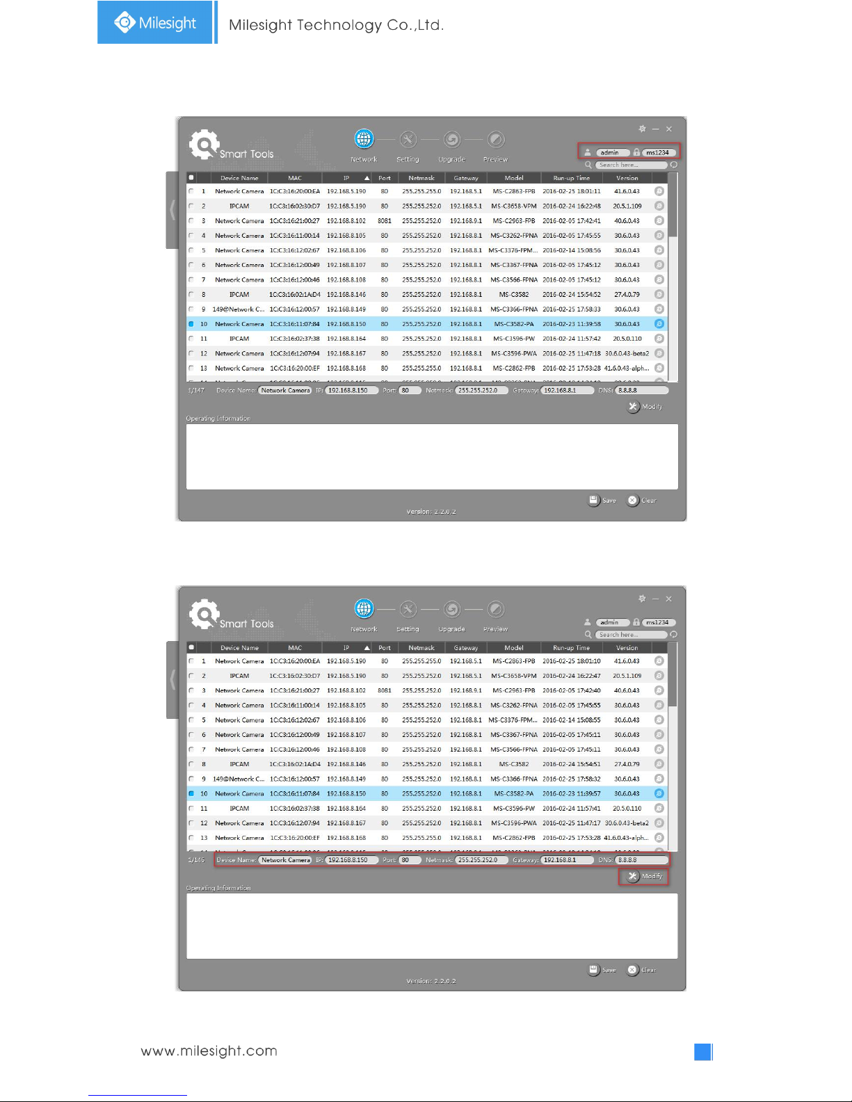
Step2: Start Smart Tools, click the IPC Tools page, then enter the device information, such as IP
address, MAC address, Port number, Netmask, and Gateway, then all related Milesight
network cameras in the same network that will be displayed. Details are shown as Figure
3-1-1;
Figure 3-1-1 Smart Tools

8
Step3: Select a camera or multiple cameras according to the MAC addresses;
Figure 3-1-2 Select single camera
Figure 3-1-3 Select multiple cameras
9
Step4: Type the User Name and Password (admin/ms1234 for default, please change your
password for your device security);
Figure 3-1-4 Type the User Name and Password
Step5: Change the IP address or other network values, and then click “Modify” button;
Figure 3-1-5 Modify
10
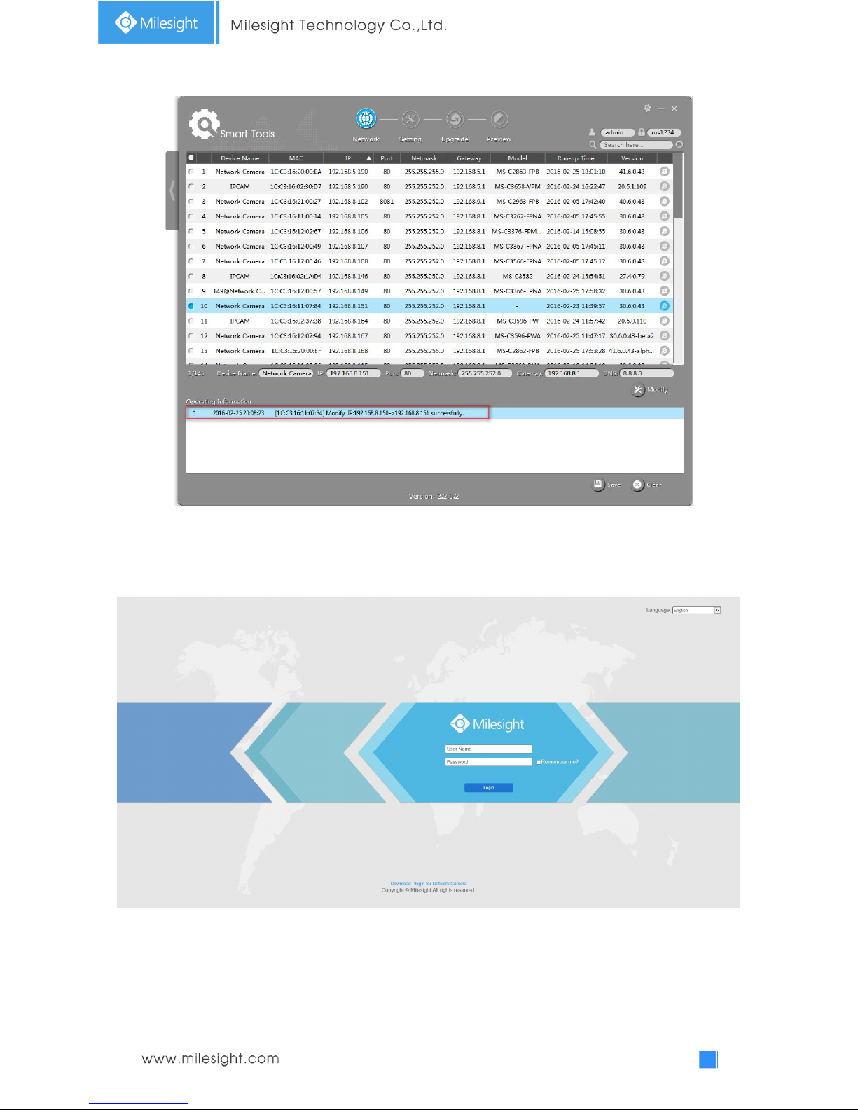
Step6: Change the IP address successfully;
Figure 3-1-6 Change IP address successfully
Step7: By double clicking the selected camera or the browser of interested camera, you can access
the camera via web browser directly. The Internet Explorer window will pop up.
Figure 3-1-7 Login interface
More usage of Smart Tools, please refer to the Smart Tools User Manual.
11
3.1.2 Assign An IP Address via Browser
If the network segment of the computer and that of the camera are different, please follow the
steps to change the IP address:
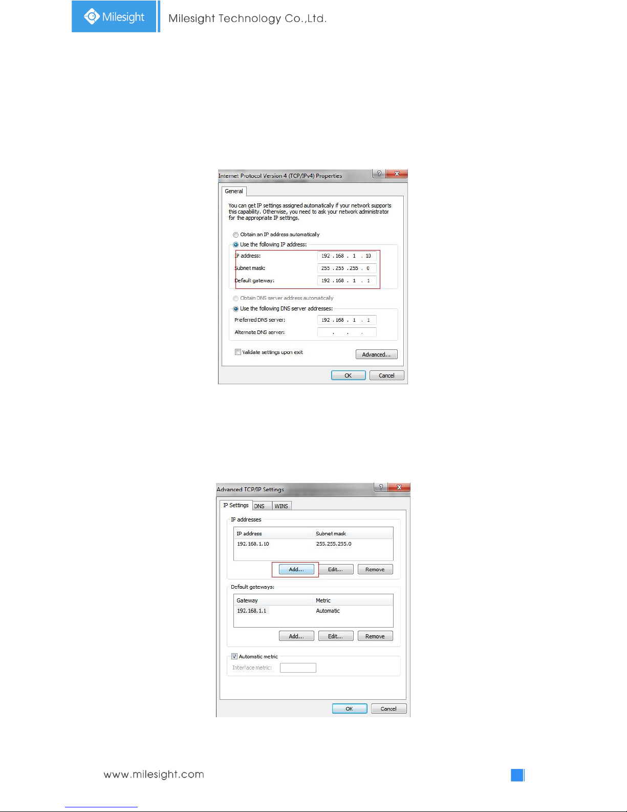
Step1: Change the IP address of computer to 192.168.5.0 segment, here are two ways as below:
a. StartControl PanelNetwork and Internet ConnectionNetwork Connection
Local Area Connection, and double click it. (Refer to Figure 3-1-8);
Figure 3-1-8 Setting Network Segment IP Address of Computer
b. Click “Advanced”, and then click “IP settings”“IP address”“Add” (See Figure
3-1-9). In the pop-up window, enter an IP address that in the same segment with
Milesight network camera ( e.g. 192.168.5.61, but please note that this IP address
shall not conflict with the IP address on the existing network);

12
Figure 3-1-9 Setting IP Address of Computer
Step2: Start the browser. In the address bar, enter the default IP address of the camera:
http://192.168.5.190;
Step3: Enter the user name and password when the LOGIN page appears;
Default user name: admin
Default password: ms1234
Figure 3-1-10 Login
Step4: After login, please select “Configuration”“Basic Settings”“Network”“TCP/IP”. The
Network Settings page appears (Shown as below Figure);
Figure 3-1-11 IP Address of Camera
13
Step5: Change the IP address or other network values. Then click “Save” button;
Step6: The change of default IP address is completed.
3.2 Accessing from the Web Browser
The camera can be used with the most standard operating systems and browsers. The
recommended browsers are Internet Explorer, Firefox, Chrome, Safari.
Access over IE Browser
Before using the browser to get access to your camera, you need to install the MsActiveX firstly.
You can refer the steps as follows:
Step1: Launch the IE browser and enter the IP address of the camera;
Step2: Enter the User Name and Password and click “Login”;
(The default user name is “admin”, password is “ms1234”)
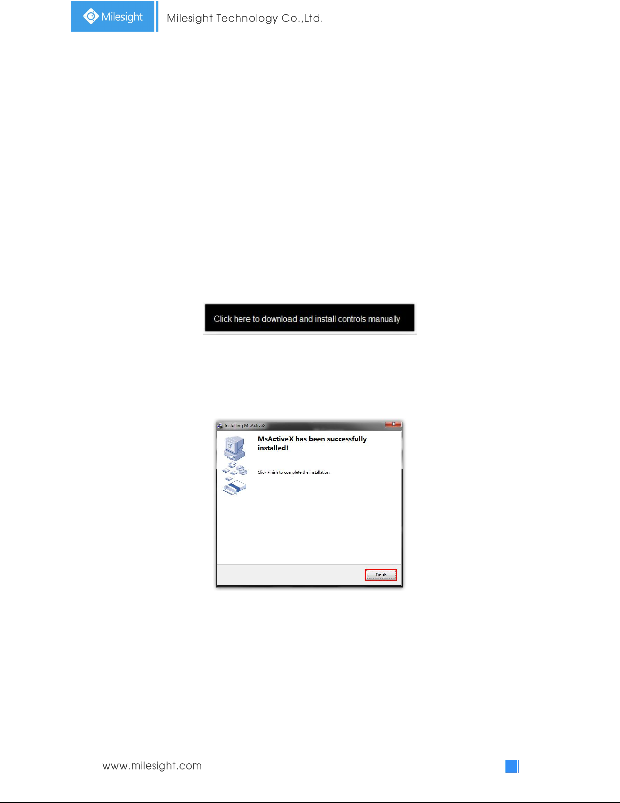
Step3: At the first time to log in the device, the browser will prompt to install Controls, please click
“Click here to download and install controls manually” as Figure 3-2-1;
Figure 3-2-1 To download and install controls
Note:
1)During installing the controls, please keep the browsers close.
Step4: Follow the prompts to install the Controls, when it`s finished, it will pop out a window as
Figure 3-2-2. Please click “Finish” and refresh the browser, then you will see the video.
Figure 3-2-2 Finish installation
If IE9 or higher version browser is used, it is suggested that the Milesight camera web link should
be added as a trusted site. See the instructions as follows:
Step1: Start the IE9 or higher version browser, and select “Tools”“Internet Options”;
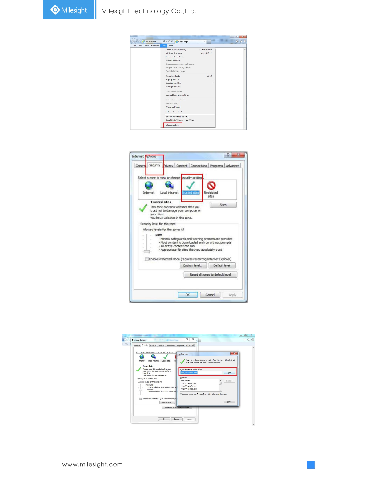
14
Figure 3-2-3 To add the permission
Step2: Select “Security” to “Trusted”;
Figure 3-2-4 To trust the control
Step3: Enter the IP address of the camera in the blank and click “Add”;
Figure 3-2-5 Add the website to the zone
15
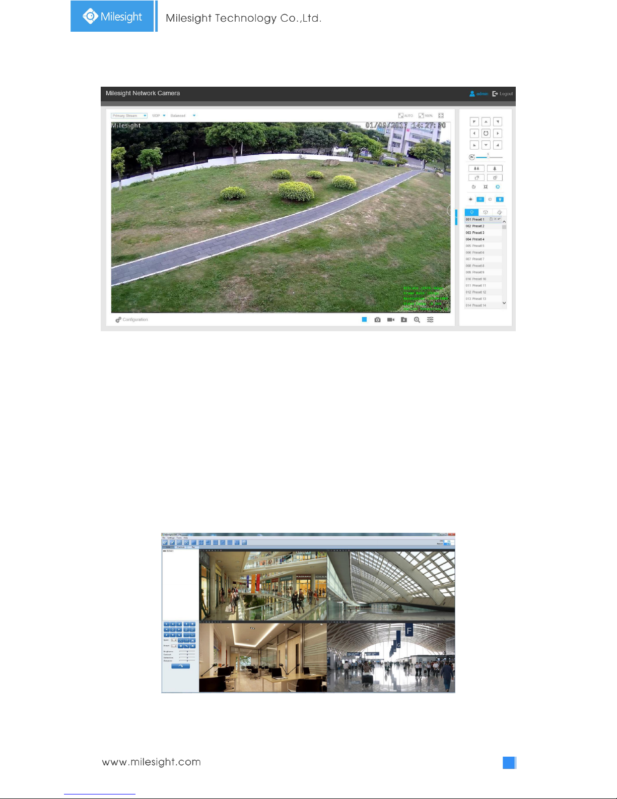
Step4: Enter the IP address. After logging on network camera’s web GUI successfully, user is
allowed to view live video as follows.
Figure 3-2-6 Live View Interface
3.3 Accessing from Milesight VMS (Video Management Software)
Milesight VMS(ONVIF compatible) is a handy and reliable application designed to work with
network cameras in order to provide video surveillance, recording settings and event management
functions. The interface of Milesight VMS is very easy to use, intuitive, with easy access to the
most common activities, such as viewing live video, searching through recordings and exporting
videos and snapshots. It's able to be integrated with other devices through ONVIF. It is designed to
work on Windows XP/7/8/Vista/ Server 2000/ Server 2008. The software could be downloaded
from our website www.milesight.com.
Please install Milesight VMS; then launch the program to add the camera to the channel list. For
detailed information about how to use the software, please refer to user manual of Milesight VMS.
Figure 3-3-1 Milesight VMS Live View
16
Chapter IV System Operation Guide
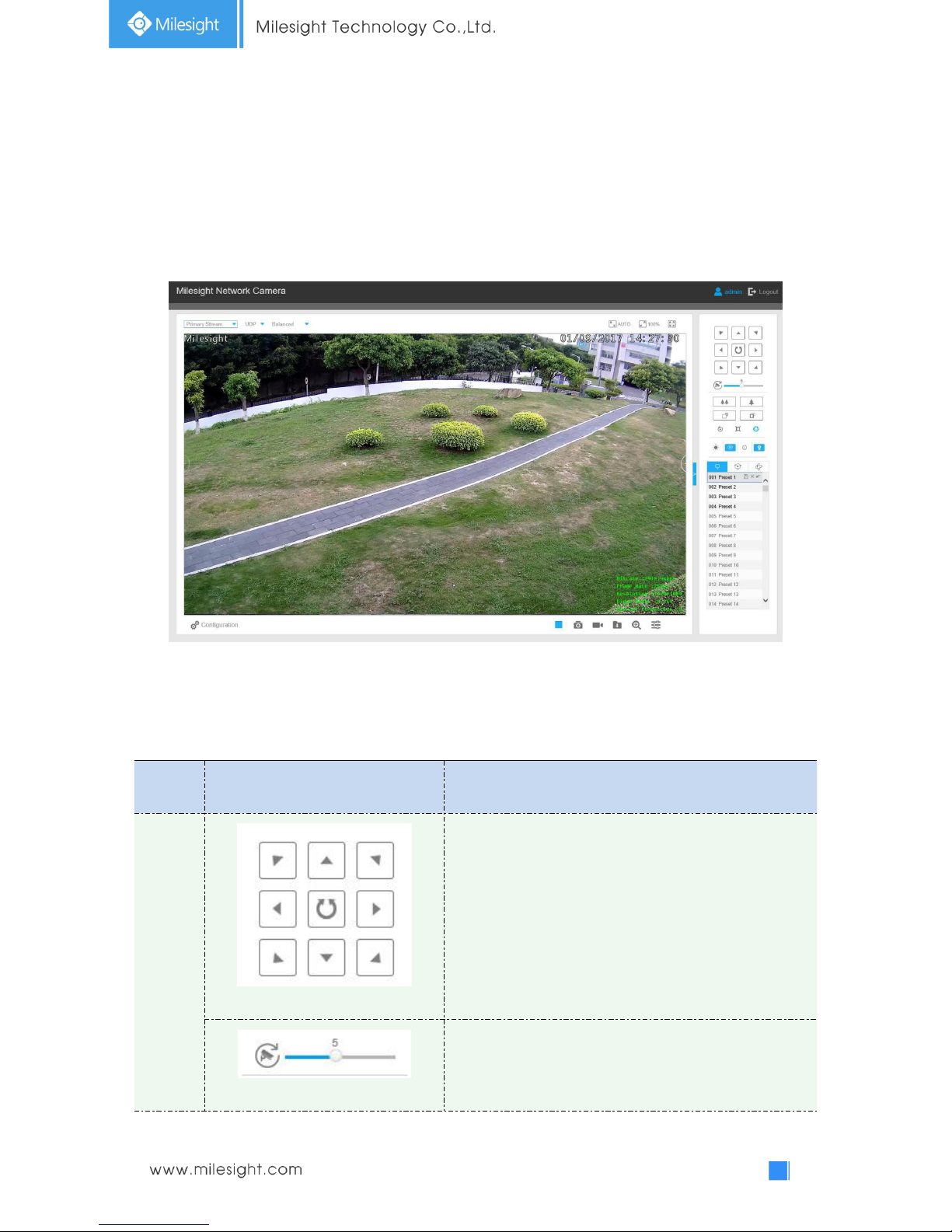
4.1 Live Video
After logging in the network camera web GUI successfully, you are allowed to view live video as
follows.
Figure 4-1-1 Live view interface
4.1.1 Operations on Live View Page
Table 4-1-1 Description of the buttons
No.
Parameter
Description
1
PTZ Control
Navigation key is used to control the direction. The rotation
key is used for auto-rotation.
PTZ Speed
To adjust the speed of pan/tilt movements, from 1 to 10
17
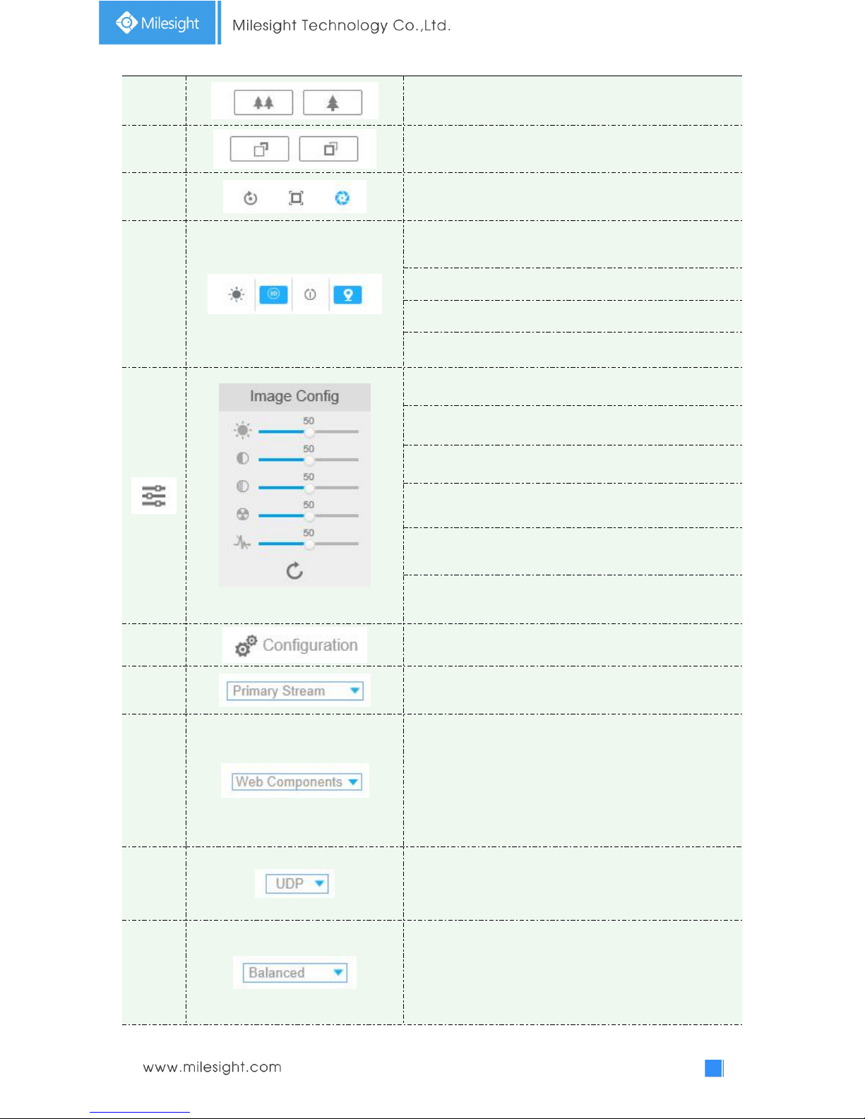
2
Click to zoom in and zoom out
3
Click to focus near or far of the lens.
4
Lens Initialization, Auxiliary Focus and Auto Iris
5
Lighting For 30s:
Click to open/ close the White LED for
lighting 30s.
3D Positioning: Click to enable/ disable 3D positioning.
One-touch Patrol:
Click to carry out the patrol.
Auto Home: Click to enable Auto Home.
Image Config
Brightness: Drag to adjust brightness of the image.
Contrast: Drag to adjust color and light contrast.
Saturation: Drag to adjust color saturation of the image.
Sharpness: Drag to enhance the detail of the image by
sharpening the edges in the image.
Noise Reduction Level: Drag to adjust the noise reduction
level.
Default: Drag to restore brightness, contrast and saturation
to default setup.
8
Configuration: Click to access the configuration page.
9
To choose the Stream(Primary/Secondary/Tertiary)to be
shown on the current video window.
10
Web Components: Support Firefox, Safari, Chrome; need to
install the component to display the view;
MJPEG: Support to display the view on Firefox, Safari,
Chrome;
(NOTE: IE chooses Web Components mode as default. In
this case, the options will not appear. )
11
TCP: More reliable connection;
UDP: More instantaneous connection, but if you cannot get
the live view successfully, please turn into TCP connection.
12
Least Delay: The most instantaneous mode in the three
modes;
Balanced: A balanced mode between Least Delay and
Best Fluency, maintains the fluency while keeps an
acceptable delay;
18
Best Fluency: The most fluent mode in the three modes.
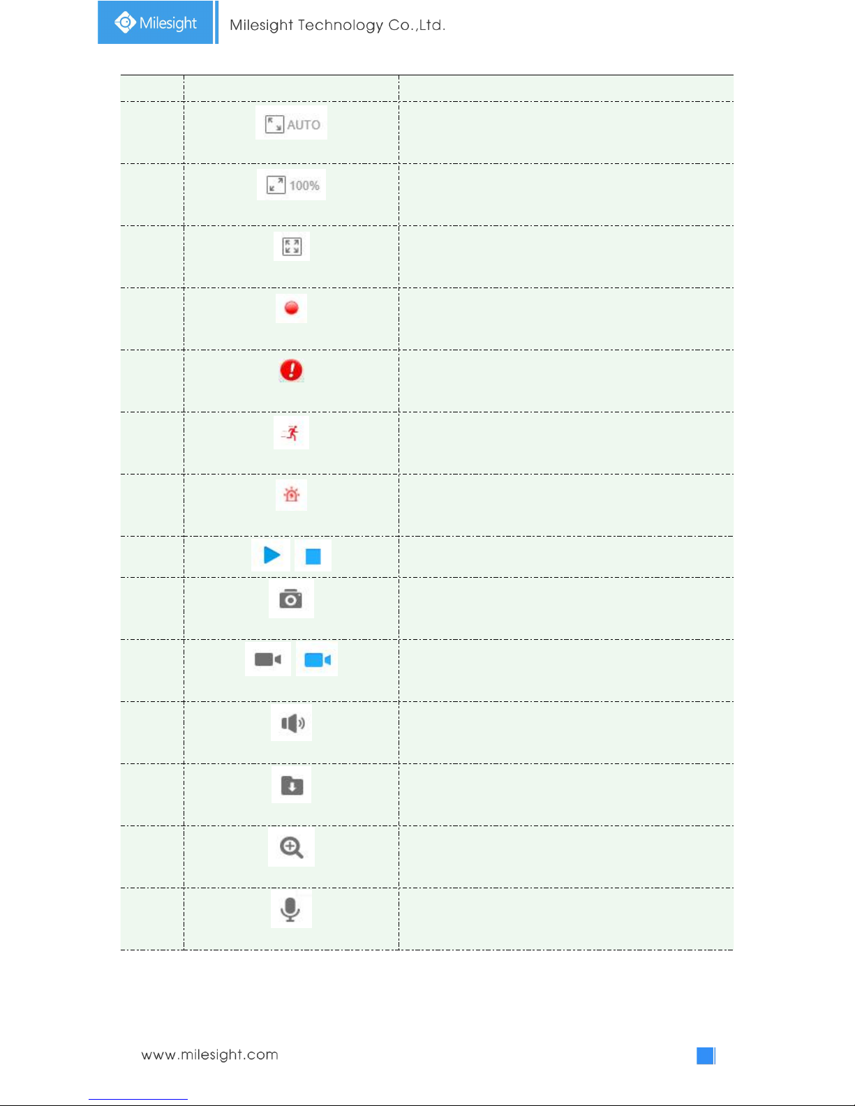
13
Window size
Click to display images at a window size.
14
Real size
Click to display images at a real size.
15
Full Screen
Click to display images at full-screen.
16
Recording
When recording, the icon will turn red.
17
Alarm
When an alarm of Smart Event was triggered, the icon
appears
18
Alarm
When an alarm of Motion Detection was triggered, the
icon appears
19
Alarm
Except for the two kinds of alarms above, when other
alarms were triggered, the icon appears
20
/
Click to start/stop Live View.
21
Capture
Click to capture the current image and save to the
configured path. The default path is
C:VMS\+-1\ IMAGE-MANUAL.
22
/
Start/Stop Recording
Click to start recording video and save to the configured
path. The default path is
C:VMS\+-1\MS_Record. Click again to stop recording.
23
Play Audio
Click to enable Audio Input/Output. It can also be set in
Audio configuration page.
24
Saving Path Settings
Click to set the saving path for captured images and video
recordings of operating on the live view.
25
Enable Digital Zoom
When it is enabled, you can zoom in within a specific area
of video image via your mouse wheel.
26
Start Talking
When it is enabled, you can start real-time talking.
19
4.1.2 3D Positioning
3D Positioning allows user to use mouse clicking and dragging to control the PTZ.
Steps:
1.Click on the toolbar of Live View interface.
2.Operate the 3D positioning function
Left click a position of the Live View, the corresponding position will be moved to the
center of the Live View.
Hold down the left mouse button and drag the mouse to the lower right or upper right on
the Live View, you can see a blue rectangle. The corresponding position will be moved to
the center of the Live View and Zoom in.
Hold down the left mouse button and drag the mouse to the lower left or upper left on
the Live View, you can see a blue rectangle. The corresponding position will be moved to
the center of the Live View and Zoom out.
The Bigger the rectangle is, the smaller zoom in/out will be acted.
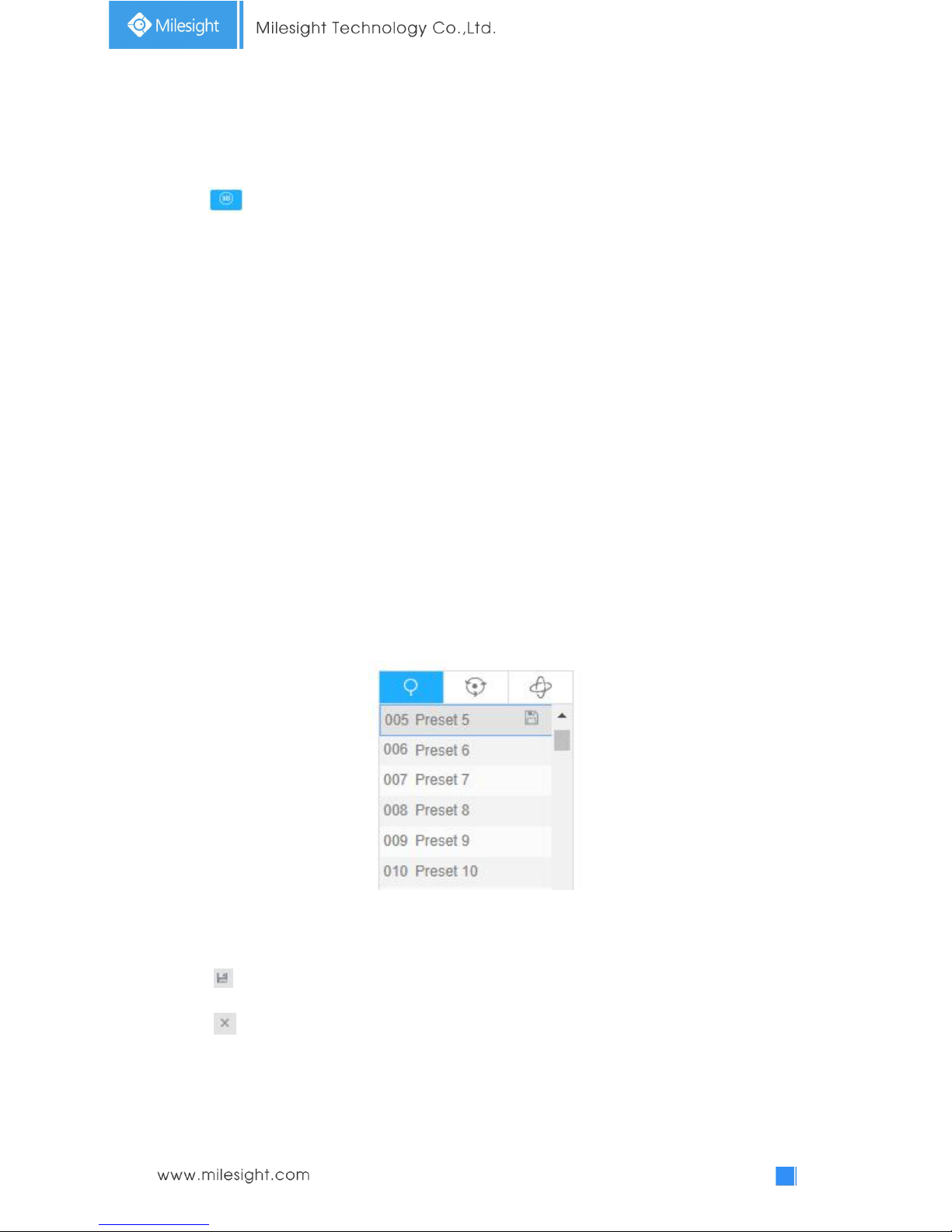
4.1.3 Set / Call a preset / Patrol / Pattern
A preset is a predefined image position. You can click the call button from the preset list to quickly
go to the desired image position.
Set a preset:
Step1: In the PTZ control panel, select a preset number from the preset list;
Figure 4-1-2 Set a Preset
Step2: Use the PTZ control buttons to move the lens to the interested position;
Step3: Click to save the setting of the current preset;
Step4: Click to delete the chosen preset.
Note:
Up to 237 presets can be configured (18 presets are not modifiable).
20
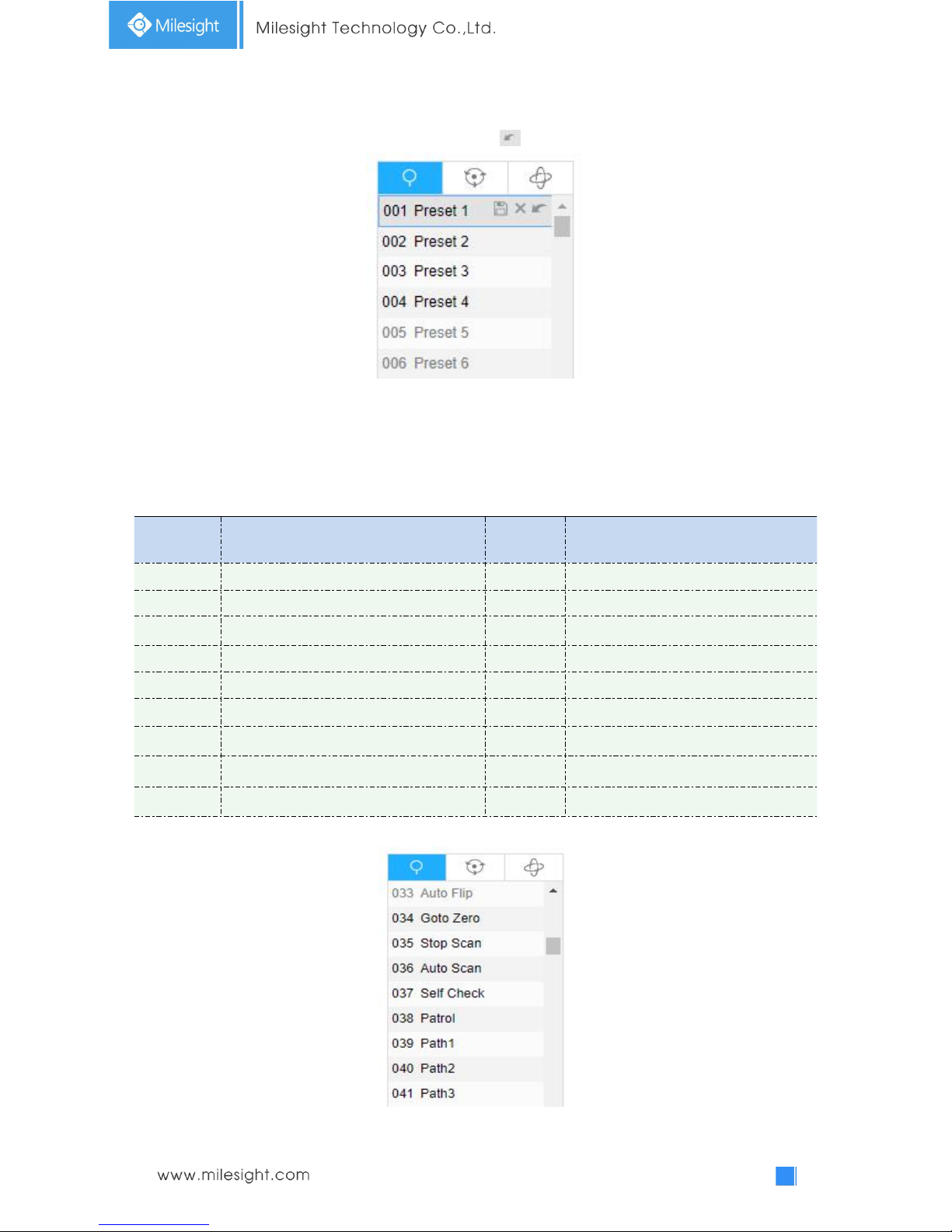
Calling a preset:
Select a defined preset form the preset list and click to call the preset.
Figure 4-1-3 call a Preset
Note:
The following presets are predefined with special commands. You can only call them but can’t
configure them. For example, preset 037 is the “Self Check”. If you call the preset number 037, the
PTZ camera will start self check function at once.
Table 4-1-2 Special Presets
Special
Preset
Function
Special
Preset
Function
33
Auto Flip(Speed Dome only)
42
Path4
34
Goto Zero
43
Path5
35
Stop Scan
44
Path6
36
Auto Scan
45
Path7
37
Self Check
46
Path8
38
Patrol
47
Pattern1
39
Path1
48
Pattern2
40
Path2
49
Pattern3
41
Path3
50
Pattern4
Figure 4-1-4 Special Presets
21
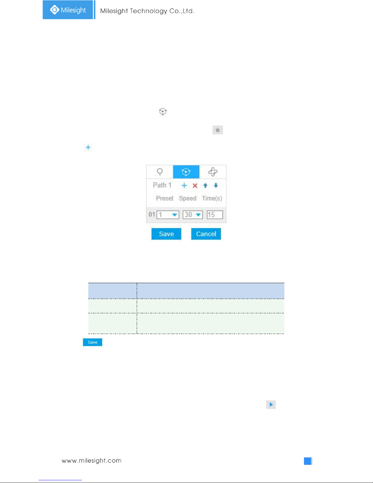
Set / Call a patrol
A patrol is a memorized series of preset function. It can be configured and called on the patrol
setting list. You can customize up to 8 patrols and it can be configured with 48 presets. Before
configuring the patrol, you should make sure that the presets you want to add to the patrol have
been defined.
Set a patrol:
Step1: In the PTZ control panel, click to enter the patrol settings interface;
Step2: Select a patrol number, the setting icon will appear , click it;
Step3: Click to add presets to this patrol, as shown in Figure 4-1-5;
Figure 4-1-5 Configure a Patrol
Step4: Configure the preset number, patrol speed and patrol time;
Table 4-1-3 Description of Patrol Settings
Name
Description
Patrol Speed
The speed of moving from one preset to another.
Patrol Time
The duration staying on one patrol point. The PTZ camera
moves to another patrol point after the set patrol time.
Step5: Click to save the patrol settings.
Note:
A. Patrol Speed only works in Patrol mode.
B. Patrol Time should be 15~120s for Mini (PoE) PTZ Bullet and 0~120s for Speed Dome.
Call a patrol:
In the PTZ control panel, select a defined patrol from the patrol list, and click to call the patrol,
as shown in Figure 4-1-6.
 Loading...