

Page 1

Electric Winch
Assembly and Operating
Instruction Book
Model PE 4500
Part Number 76-50115
Pulling capacity 4500 lb
*
Single Line
*
Power In - Power Out
*
Permanent Magnet DC Motor
*
12 Volt
*
Free Spool
2121 Blount Road Pompano Beach, FL 33069
Phone (800) 886-8647 (954) 782-0604 Fax (954) 782-0770
Page 2
Model PE 4500
P/N 76-50115
Features:
¾ Planetary gear system for fast line speed
¾ Automatic load-holding brake
¾ Free spooling
¾ Power In and Power Out
¾ 1.4 kw (1.9 hp) heavy duty electric permanent magnetic motor
¾ Low electric current
Specifications:
¾ Rated line pull………...4500 lbs. (2041 kgs.) Single line
¾ Gear Reduction ratio...294:1
¾ Motor……………….….Permanent magnet 1.4 kw (1.9 hp), 12 volt
¾ Drum Size………….…Diameter 2.5 inches (63mm) x Length 5.512 inches (140 mm)
¾ Cable supplied…….....1/4 inches (6 mm) x 80 ft. (24.5m) aircraft cable (min. break force 7000 lbs.)
¾ Overall dimension…....(Length x Width x Height) 17.165 in. x 6.2 in. x 7.3 in. (436mm x 1152.4mm x 185mm)
¾ Net Weight……………51 lb (23 kg)
¾ Mounting bolt pattern...6.535 inches x 4.5 inches (166 mm x 114.3 mm)
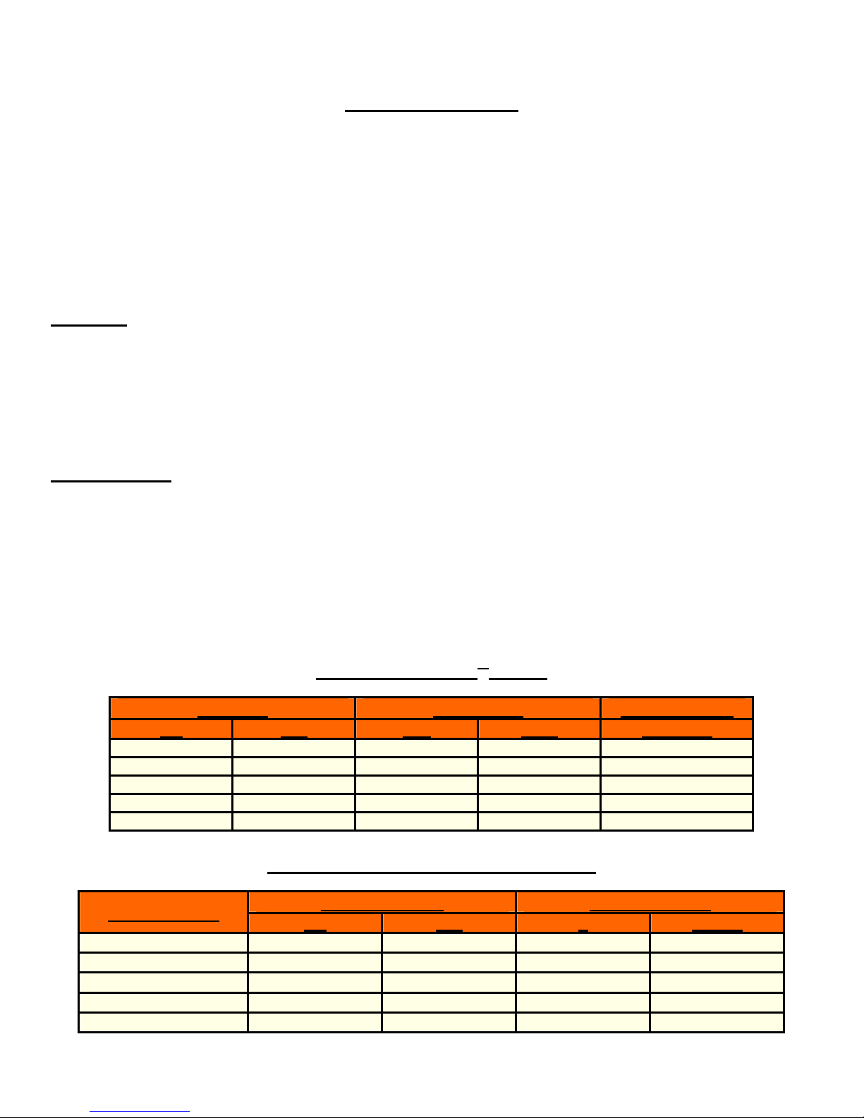
Performance of 1st Layer
Line Pull Line Speed Motor Current
lbs kgs fpm mpm 12 V Amp
0 0 14 4.3 35
1500 680 6.6 2 80
2200 998 5.2 1.6 100
3000 1361 4.6 1.4 145
4500 2041 3.3 1 170
Line pull & Cable Capacity by layer
Cable Layer
1 4500 2041 14 4.3
2 3880 1760 31.5 9.6
3 3420 1551 50 15.2
4 3050 1384 70 21.2
5 2750 1247 80 24.5
Rated Line Pull Cable Capacity
lbs kgs ft meters
1
Page 3

Safety Warnings & Precautions
When using this winch, safety precautions should always be followed to reduce the risk of personal
injury and damage to the winch.
1) LEARN TO USE YOUR MILE MARKER WINCH:
a. After winch has been installed, take some time and practice using it so you will be
familiar with ALL OPERATIONS. Periodically check the winch installation to ensure
that all bolts are tight.
b. Maintain your tools with care. Keep all of the tools clean and in good working
condition. Before using, check and see if there is any part that appears damaged that
may affect proper operation. Any damaged part should be properly repaired and
replaced using identical parts by a qualified technician.
2) KEEP WINCHING AREA CLEAR:
Do not allow people to remain in the area during winching operations. Do not step over a taut
wire rope or allow anyone else to do so. Direct all personnel to stand clear of any possible
pathway the object being pulled could possibly move should a cable break. A snapped cable
could cause winch failure, injury or death. Keep proper footing and balance at all times. Do not
reach over or across the winch and/or pulling cable while the winch is in operation.
3) INSPECT WIRE ROPE AND EQUIPMENT FREQUENTLY:
The wire rope should be for damage that could reduce it’s breaking strength. A frayed rope
with broken strands should be replaced immediately. Always replace the rope with a rope that
is rated to sustain any load that the winch is capable of pulling. Any substitute must be
IDENTICAL in strength, quality, lay and stranding to the Mile Marker cable originally supplied.
4) WORKING AREA CONDITIONS:
Keep the working area well lit. Do not use this winch in the presence of flammable gases or liquids.
5) KEEP CHILDREN AWAY:
Keep children away from working area. Never let children operate the winch.
6) DRESS PROPERLY:
Do not wear loose clothing or jewelry as they can be caught in moving parts. Protective, electrically
non-conductive clothes and non-skid footwear is the only type of clothing you should be using when
operating the winch. Wear restrictive hair covering to contain long hair.
7) USE LEATHER GLOVES:
When handling or rewinding wire rope always use hand protection to eliminate the possibility of
cuts caused by burrs & slivers from broken strands.
8) DRUM ROPE:
Always make sure that there are at least 5 complete turns of rope left on the drum before
winching since the rope fastener from broken strands.
9) KEEP HANDS AND FINGERS CLEAR OF WIRE ROPE AND HOOK WHEN OPERATING
WINCH:
Never put your finger through the hook when reeling in the last few feet. If your finger should
become trapped in the hook or rope, you could lose your finger. Never guide a wire rope under
tension onto the drum with your hand.
10) NEVER HOOK THE ROPE BACK ONTO ITSELF:
Holing the rope back onto itself creates an unacceptable strain, breaking individual strands,
which in turn weakens the entire wire rope.
2
Page 4
Safety Warnings & Precautions Continued
11) KEEP PULLING DURATIONS AS SHORT AS POSSIBLE:
The winch is designed for intermittent use and cannot be used in constant duty applications. Do not
pull more than one minute at or near rated load. If the motor becomes too hot to touch, stop and let it
cool off for a few minutes. If the motor stalls, cut off the power immediately.
a.
DO NOT OVERLOAD:
Always use this winch at its rated capacity for your safety and for better performance. Do not
use inappropriate attachments in an attempt to exceed its rated capacity.
12) AVOID CONTINUOUS PULLS FROM EXTREME ANGLES:
This will cause the rope to pile up at one end of the drum. When possible, please get the rope
as straight as possible to the direction of the object.
13) NEVER OPERATE THE WINCH WITHOUT THE ROPE FAIRLEAD FITTED:
Operator injury or winch damage can result if a fairlead is not installed.
14) STAY ALERT:
Watch what you are doing. Use your common sense. Do not use this winch when you are tired,
stressed or
WHEN UNDER THE INFLUENCE OF DRUGS, ALCOHOL OR MEDICATION.
15) DISCONNECT SWITCH:
Unplug switch when not in use.
16) REPLACEMENT PARTS & ACCESSORIES:
When servicing, use only identical replacement parts. Use of any other parts will void the warranty.
Approved accessories are available from your local distributor.
Winch Warnings & Precautions
1) Keeps hands and body away from Fairlead (cable intake slot) when operating.
2) Secure vehicle in position before using winch.
3) Do not exceed winch load weight capacity (see Specifications on Page 1).
4) Be certain winch is properly bolted to a structure (or vehicle) that can hold the winch load.
5) Always use proper couplings when connecting winch cable hook to load.
6) Do not lift items vertically. The winch was designed for horizontal use only.
7) Do not overload the winch (see Specifications on page 1). It will do the job better at the load it
was intended.
8) Do not use inappropriate attachments to extend the length of the winch cable.
9) Never lift people or hoist loads over people.
10) Never come in between the winch and the load when operating.
11) Do not apply load to winch when cable is fully extended. Keep at least 5 full turns of cable on
the reel.
12) After moving an item with the winch, secure the item. Do not rely on the winch to hold it for an
extended period.
3
Page 5

Winch Warnings & Precautions (Continued)
13) Examine winch before using. Components may be affected by exposure to everyday
weathering, chemicals, salts, and rust.
14) Never fully extend cable while under load. Keep 5 complete turns of cable around the winch
drum.
15) When loading a boat into a trailer without reel or side hull rollers, make sure the trailer is
submerged in the water when the boat is loaded by the winch. Attempting to drag the boat on
to the trailer while on land can cause winch failure and possible injury.
16) Never operate winch if cable shows any signs of weakening, is knotted or kinked.
17) Winch does not have a locking mechanism. Secure load after moving.
18) Do not cross over or under the cable while it is in process of loading.
19) Do not move vehicle with cable extended and attached to load to pull it. The cable could snap.
20) Apply blocks (such as a wheel choke) to vehicle when parked on an incline.
21) Re-spool cable properly.
Warning
The Electric Winch is designed for intermittent use only, and should not be used in a constant
duty application. The duration of the pulling job should be kept as short as possible. If the
Winch motor becomes very hot to touch, stop the winch and let it cool down for several
minutes. Never pull for more than one minute at or near the rated load. Do not maintain power
to the winch if the motor stalls.
UNPACKING
When unpacking, check to make sure all parts are included. Refer to Assembly Drawings and
Parts Lists behind. If any part is missing or broken, please call Mile Marker at the number on
the cover of this manual as soon as possible.
Installation
STEP 1 Mount electric winch to the vehicle using Cap Screw (37), Nut (34), Flat Washer (35)
and Lock washer (36), all provided. If the provided hardware does not accommodate
the installation, use SAE grade 8 bolts or higher with torque to 35 ft. lbs. It should be
aligned and secured to a solid part or the vehicle (front or rear) where the full rated load
will be evenly distributed. Also remember that the winch is designed for horizontal pull,
not vertical.
STEP 2 Connect the red (positive) Battery cable from the Solenoid Assembly to the closest
screw-down positive (+) terminal to 12-volt battery.
movement.
Battery cables should not be drawn taut. Leave slack for some cable
4
Page 6

Installation Continued
STEP 3 Connect the black (negative) Battery cable from the Solenoid Assembly to the closest
screw-down negative (-) terminal to 12-volt battery.
STEP 4 Test electric winch for proper operation. Refer to the operation selection below.
STEP 5 Winch cable must be rewound onto the drum under a load of at least 500lbs. (If this
precaution is not taken, inner wraps will damage winch cable).
Operation
1. Disengage the clutch by moving the Cam Ring (29) to the OUT position.
2. Grab the Cable Assembly (4) hook and pull the cable to the desired length, then attach to
item being pulled.
Always leave at least 5 turns of cable on the drum. Review winch safety warnings &
precautions on pages 2 & 3 before continuing.
3. Re-engage the clutch by moving the Cam Ring (29) to the IN position.
4. Lift the Female Connector Cover (21) exposing the electrical switch connector.
5. Insert the Switch Assy (5) connector into the Female Connector (20).
6. While standing aside the pulling path, press and hold the Red push button on the Switch Assy
(5). Press and hold the opposite push button to reverse directions. Wait until the motor stops
before reversing directions.
7. When the pulling is complete, remove the Switch Assy (5) from the Female Connector (20) and
replace the Female Connector Cover (21).
¾ It is important to make sure the winch is mounted on flat surface to guarantee the 3 major
sections of the winch (the motor end, the cable drum and the gear housing end) are properly
aligned.
¾ Run the vehicle engine during pulling operations to keep the battery charging.
¾ When pulling a heavy load, place a blanket or the similar over the cable 5 to 6 feet (1.5m to
1.8m) from the hook.
5
Page 7

MAINTENANCE
LUBRICATION:
1) All moving parts within Electric Winch having been lubricated using high temperature
2) Lubricate Cable Assembly (4) periodically using light penetrating oil.
CABLE ASSEMBLY REPLACEMENT:
1) Move Cam Ring (29) to OUT position.
2) Extend Cable Assembly (4) to its full length.
3) Remove old Cable Assembly and attach new one.
4) Retract Cable Assembly onto cable drum being careful not to allow kinking.
SYMPTOM POSSIBLE CAUSE SUGGESTED REMEDY
lithium grease at the factory. No internal lubrication is required.
*Note how the existing cable is connected to the inside of the drum*
TROUBLE SHOOTING
Motor does
not turn on
Motor runs too hot
Motor runs slowly
or without normal
power
Motor runs but
cable drum does
not turn
-Switch Assy not connected
properly
-Loose battery cable *Tighten nuts on cable connectors
-Solenoid malfunctioning *Tap solenoid to free contact, applying
-Defective Switch Assy *Replace Switch Assy.
-Defective motor *Check for voltage at armature port with
-Water has entered motor *Drain and dry. Run in short bursts
-Long period of operation *Let winch cool down periodically.
-Battery runs down *Recharge battery by running vehicle
-Insufficient current or
voltage
-Clutch (Cam Ring) not
engaged
*Insert Switch Assy firmly to the
connector.
12 volts to coil terminal directly.
Make an audible clicking when activating.
switch pressed. If voltage is present,
replace motor.
without load until completely dry.
engine.
*Clean, tighten or replace the connector.
*Push Cam Ring (29) into IN position. If
that does not work, as a qualified
technician to check and repair.
Motor runs in one
-Defective or stuck solenoid *Tap solenoid to free contacts. Repair or
direction only
-Defective Switch Assy *Replace Switch Assy
replace solenoid.
6
Page 8

Solenoid Assembly Drawing
With Kill Switch
Parts List for Solenoid Assembly
Item # Description Quantity
1
2
3
4
5
6
7
8
9
10
11
12
13
14
15
16
17
18
19
20
Wire Assembly-black 10 Ga x 76 mm
Wire Assembly-black 16 Ga x 38 mm
Wire Assembly-black 16 Ga x 89 mm
Wire Assembly-black 6 Ga x 152 mm
Strap-copper
Connector Assy. Female
Connector Cover Female
Screw M6 x 12mm
Screw M6 x 20mm
Nut H x M6
Washer-Flat
Lock Washer
Washer-Shake proof
Bracket
Terminal Tab
Solenoid
Wire Assy-Battery Red 1.5m
Wire Assy.-Battery Black 1.5m
Strap-Copper
Solenoid Cover
1
1
1
2
1
1
1
1
1
2
4
6
4
1
2
1
1
2
1
3
7
Page 9

Winch Parts List & Assembly Drawing for the PE 4500
ITEM QTY
1
2
3
4
5
6
7
8
9
10
11
12
13
14
15
16
17
18
19
20
21
22
1
1
1
1
1
1
1
1
1
6
1
1
2
3
1
1
1
1
1
1
1
1
PART NUMBER DESCRIPTION
76-50140-01
76-50140-02
76-50140-03
76-50115-04
76-50140-05
76-50115-06
76-50115-07
76-50115-08
76-50115-09
76-50140-10
76-50115-11
76-50115-12
76-50140-13
76-50140-14
76-50140-15
76-50140-16
76-50115-17
76-50140-18
76-50115-19
76-50140-20
76-50140-21
76-50140-22
Gear Carrier Assy. Input
Gear Carrier Assy. Intermediate
Gear Carrier Assy. Output
Cable Assy. 80ft x 1/4 in.
Switch Assy.
Solenoid Assy.
Motor End Bearing Assy.
Brake / Shaft Assy.
Drum
Screw M5 x 12
Gear Housing Cover
Gasket
Drum Bushing
Thrust Washer
Thrust Disc
Gear input-sun
Gear Intermediate Sun
Cap Screw M6 x 10
Cable Anchor
Roll pin D3 x 10
Shaft Bushing
Gear Output-sun
ITEM QTY
23
24
25
26
27
28
29
30
31
32
33
34
35
36
37
***When ordering parts from this list, make sure to indicate the
exact part number for your replacement and that it is from the
Winch Parts List***
PART NUMBER DESCRIPTION
6
2
1
1
2
2
1
2
1
6
1
4
6
1
6
76-50140-23
76-50140-24
76-50140-25
76-50115-26
76-50115-27
76-50115-28
76-50140-29
76-50115-30
76-50140-31
76-50140-32
76-50115-33
76-50140-34
76-50140-35
76-50115-36
76-50140-37
Cap screw M 6 x 19
Brake Shoes
Gear retainer ring
Gear ring
Bolt M6 x 20
Spring Washer D6
Cam Ring
Tie Bar
Locking Ring
Spring
Mounting leg
Nut M 10
Spring Washer D4
Roller Fairlead WH-4
Screw M10 x 34
8
Page 10

Roller Fairlead
Specifications Description
Model
Cable opening (mm)
Roller Sizes (mm) Vertical
Horizontal
Application (used on)
Overall dimensions (mm)
Weight (kgs)
Model WH-4
105 L x 19 W
35 D x 87 H
35 D x 119 L
PE 4500
PE 6000
212 L x 108 W x 78 H
3.19
9
Page 11

MILE MARKER, INC.
Mile Marker, Inc. offers a limited two (2) year warranty (to the original retail purchaser) for each new
Mile Marker consumer/RV electric winch against manufacturing defects in workmanship and
materials on all the mechanical components.
¾ Electrical components consisting of motors, solenoids, wiring, wire connectors and
associated parts have a limited one (1) year warranty.
¾ New cable assemblies are warranted against defects in workmanship and materials
when received by the retail purchaser. There is no applicable warranty after initial use.
Warranty registration cards for each winch must be submitted at the time of purchase or within 30
days by the end user. Warranty will only be valid for the original purchaser of the winch and installed
on the vehicle for which it was originally registered.
Mile Marker electric winches are intended for recreational self-recovery usage. The warranty is void if
the winch is used in commercial/industrial applications.
The obligation under this warranty, statutory or otherwise, is limited to the replacement or repair at the
manufacturer’s factory, or at a point designated by the manufacturer, of such part(s) as shall appear
to the manufacturer, upon inspection of such part(s) as shall appear to the manufacturer, upon
inspection of such part(s), to have been defective in material or workmanship. This warranty does not
obligate Mile Marker, Inc. to bear the cost of labor or transportation charges in connection with the
replacement or repair of defective parts, nor shall it apply to a product upon which repairs or
alterations have been made, unless authorized by the manufacturer, or for equipment misused,
neglected or improperly installed.
IMPORTANT NOTICE:
To the fullest extent permitted by applicable law, the following are hereby excluded and
disclaimed:
1) All warranties of fitness for a particular purpose;
2) All warranties of merchantability;
3) All claims for consequential or incidental damages.
There are no warranties that extend beyond the description that appears on the face hereof.
Some states do not allow the above exclusions or disclaimers in consumer transactions and as such
this disclaimer/exclusion may not apply to you.
To the extent such warranties of fitness or merchantability are deemed to apply to this product, they
exist for only so long as the express limited warranty elsewhere set forth is in existence.
Item Number Qty. Description
1
2
3
4
5
6
7
8
LIMITED 2 YEAR WARRANTY
ELECTRIC WINCH
8 Cap Nut
8 Star Washer
2 Short Shaft
2 Nylon Bush
2 Short Roller
2 Long Shaft
2 Long Roller
1 Frame
10
Page 12

Mile Marker, Inc. reserves the right to change, alter or improve its products in design, materials or
appearance without incurring any obligation to incorporate such changes in products that were
previously manufactured.
This Warranty gives you specific legal rights and you may have other legal rights, which vary from
state to state.
To submit a warranty claim contact:
Mile Marker Inc.
Warranty Administrator
2121 Blount Road
Pompano Beach, FL 33069
Toll Free: 1-800-886-8647
2121 Blount Road Pompano Beach, FL 33069
Phone
First Name:
Last Name:
Age:
Sex:
Marital Status:
Level of Education:
City/Province:
Zip/Postal Code:
Country:
Telephone Number:
Email Address:
Which Mile Marker winch did you
Model Number:
Serial Number:
Date of Purchase:
Where did you purchase this product?
Store or catalog name:
Store location:
(800) 886-8647 (954) 782-0604 Fax (954) 917-3398 Email: warranty@milemarker.com
How satisfied were you with the dealer
and/or sales staff?
Who installed or will install your Mile
Marker product?
Is this the first time you have purchased
a winch?
If no, what brand have you bought
before?
What type of vehicle will this Mile Marker
winch be installed on?
Is this vehicle two or four wheel drive?
What is the vehicles main use?
What other accessories have you
purchased for your vehicle?
Pickup:
Year: Make: Model:
11
Page 13

Do you belong to any 4-Wheel drive
club? Yes or No
If so, what is the Club name:
What factors most influenced the purchase of your Mile Marker product? (Check all that apply)
Mile Marker reputation
□
Previous experience with Mile Marker Inc.
□
Friend/Relative recommendation
□
Salesperson’s recommendation Salesperson Name: _______________ _________________
□
Compatibility with vehicle
□
Quality/Durability
□
Warranty
□
Availability
□
□
□
□
□
Price
Internet
Advertising
Mile Marker Inc. Electric Winch Line
12
Page 14

To see all of Mile Marker’s Product Lines, please visit our website at: www.milemarker.com
13
 Loading...