

Mikro X80 User Manual
X80 Power Factor Regulator Quick Reference Guide
Side View
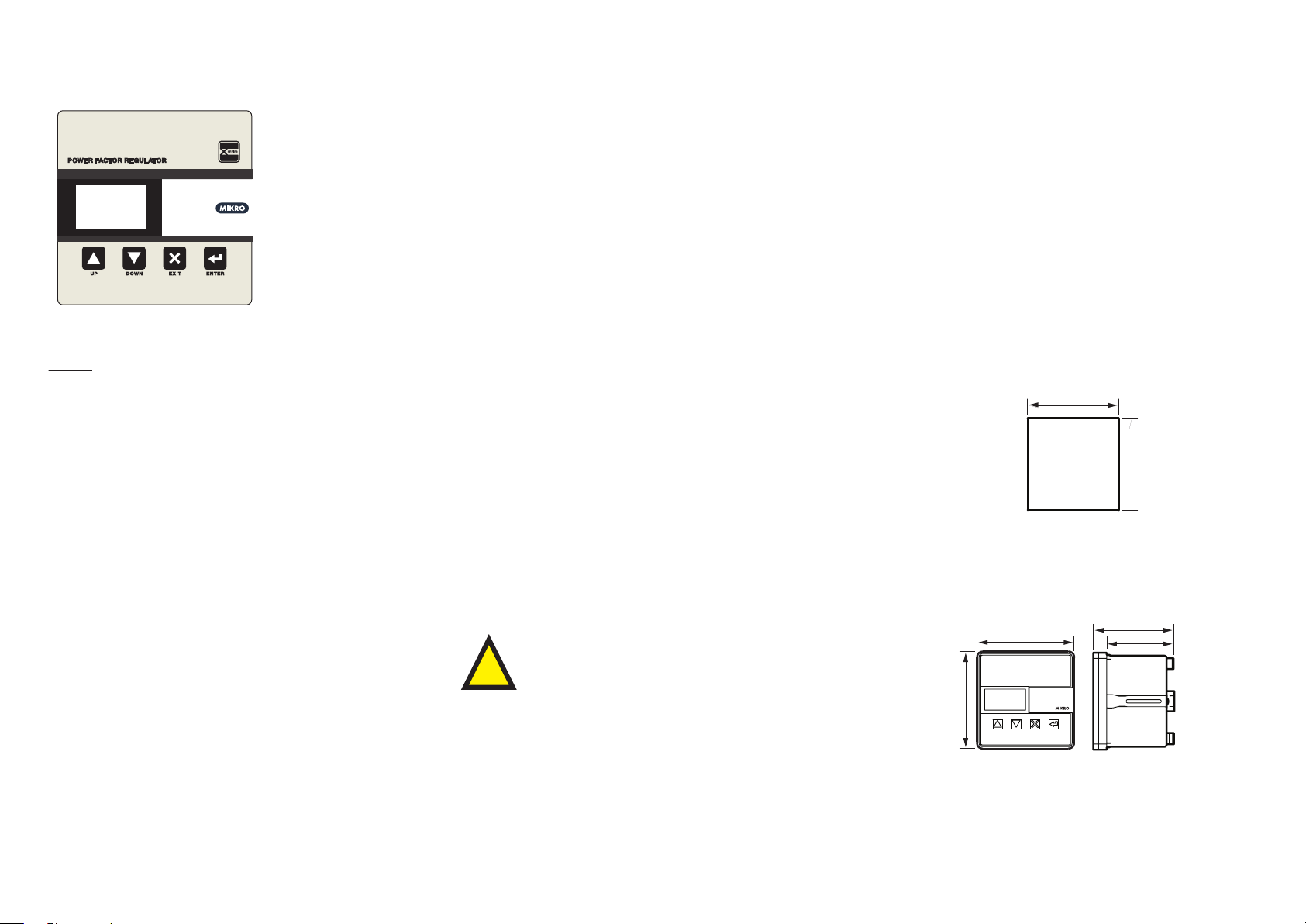
122mm
Front View
144mm
A Brief Overview
X80
Keypad
UP, DOWN, EXIT and ENTER are used to navigate through the menus
and adjust the settings.
1. General Description
Mikro®’s power factor regulator X80 is designed to detect and
compensate displacement power factor caused by inductive load by
switching in banks of capacitors. As oppose to traditional regulator
that only measures reactive power on a single phase basis but
compensates three phases, the X80’s Three Phase model is a true three
phase system as reactive power of all three phases are measured
individually and compensated optimally.
Mikro®’s power factor regulator X80 also provides exibility in conguring (or disabling) dierent levels of alarms. The alarms can then be
linked to dedicated signal contact to alert the users of potential issues
such as under compensation (thus avoiding penalty charges from the
utilities).
Mikro®’s power factor regulator X80 provides the user with a 2 inch
wide, 64 x 128 dot matrix LCD for displaying its various measurement
parameters such as: frequency, voltage, current, THD, active, reactive
and apparent power and temperature. The dot matrix LCD allows up to
31st order voltage and current harmonics to display in graphical and
table form.
3. Things include in Packing Box
a) 1 x X80 Power Factor Regulator
b) 2 x Steel Brackets
c) 1 x X80 Quick Reference Guide Hardcopy
4. Installation Guide
Before installing the X80, please ensure that the environment
meets the following conditions:
- Operating temperature: -5°C to +55°C
- Humidity: 56 days at 93%, 40°C non-condensing
- Dust free environment away from electrical noise and radiation.
5. Mounting
Insert the X80 through a 138mm x 138mm switch-gear panel as
shown below:
138mm
EXIT : To exit from menus, submenus or to cancel setting value
change. For X80 three phase models, at the main display page,
pressing EXIT will scroll through the display page for Phase 1,
Phase 2 and Phase 3 parameters
UP : Scroll up the menus or increase settings value.
Down : Scroll down the menus or decrease settings value.
Enter : To enter submenus or to conrm settings value change.
As per Mikro®’s power factor regulator series, it includes the automatic
C/K and rated step size detection feature for ease of commissioning for
typical inductive loads. Taking advantage of the dot matrix LCD, the
X80 also provides a guided step-by-step commissioning menu that
enables fast setup.
The regulator extends its connectivity by adopting the Modbus-RTU
protocol. Through the use of RS485 standard protocol, the user will be
able to network the regultor with other IEDS that linkto a center
monitoring station.
2. Precautions
Please read the instructions carefully before operating the
a) Before powering up X80, make sure auxiliary voltage supply does
not exceed the range given in connection diagram (i.e. 85 - 265 VAC or 110
- 370 VDC).
b) Ensure that there is no high voltage injected into terminal 13, 14, 23,
24 36, 37, 38, 39, 40, 41, 42 and 43.
c) If LCD display and AUX LED does not turn On after powering up X80,
please stop using the X80 and contact the manufacturer for service.
d) If any crack is found on the casing, please stop using the X80 and
contact the manufacturer.
equipment. The following symbols will appear throughout
this user manual to warn of potential dangers or hazardous
!
situation that will arise while operating the equipment.
138mm
Panel Cutout
6. Dimension
144mm
* For more detail information, please download full set of X80
user manual from http://itmikro.com/Contents/view/122
website.
102mm
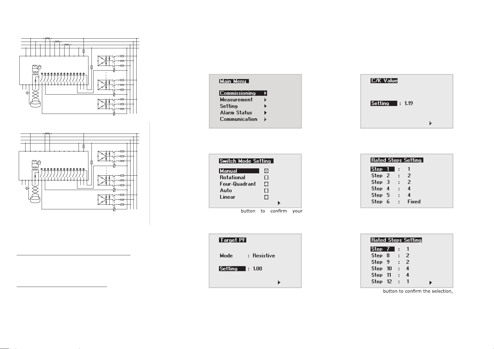
7. Connection Diagram
9. Commissioning
4432 43 42
2430
GND
T1
RS485
4432 43 42
2430
GND
T1
P1 P2
41
1 2 4 5 6 73 9 10 11 128
1423 13
12 11 9 8 7 610 4 3 2 15
N-
RP
P+
P1 P2
41
1 2 4 5 6 73 9 10 11 128
1423 13
12 11 9 8 7 610 4 3 2 15
N-
RP
P+
L1
L2
L3
N
31
T2
Thermistor
Modbus-RTU
X80 PFR120P3-240-50
L1
L2
L3
N
31
T2
Thermistor
The regulator is pre-programmed with the most common parameters as its
P1 P2
P1 P2
37 36
39 38
40
CT1
CT2
X80
OutInL3L2L1N
CT3
3435 33
N LOutOut InIn
AUX
FUSE
FUSE
SIG
FAN
K12 K2
LOAD
factory default setting. Users are normally not required to change any setting upon
commissioning. If the user requires any changes in the setting, the quick
commissioning feature will provide the user with a step-by-step guidance in setting up
all the mandatory parameters for the regulator to function properly.
1 4
2120 22
FAN
SIG
K1
LOAD
FUSE
3435 33
37 36
39 38
40
CT1
X80
N LOutInL1N
FUSE
AUX
FAN
2120 22
FAN
SIG
SIG
K12
K2
Press
2
button from Home menu.
Press
set the value. To navigate to the next
page, press or to select ““, then
press
5
button, then press or to
button.
RS485
Modbus-RTU
X80 PFR120P1-240-50
K1
8. Changing settings for X80
There are two ways to change settings for X80 which are either
through X80’s front panel or Communication port (RS485).
Change setting through RS485 communication port
User can use X-series toolkits software to change setting in PC.
This X-series toolkits can be downloaded from website http://itmikro.com/Contents/view/122
Change setting through X80’s front panel
User must unlock the password rst in order to change the settings for
X80. The default password for X80 is “0000”. The following ow chart
shows an example on how to change date:
Press
selection. To navigate to the next page,
press or to select ““, then press
button.
3
Press
set the value. To navigate to the next
page, press or to select ““, then
press
button, then press or to
button.
Press or button to navigate to the
following pages.
6
Press
and then the press or to set the
value. Back to the Main menu, press or
to select ““, then press
* For more detail information, please download full set of X80
user manual from http://itmikro.com/Contents/view/122
button.
website.
 Loading...