

Page 1
X20 Earth Fault Relay Quick Reference Guide
c
g
h
iab
d
e
f
j
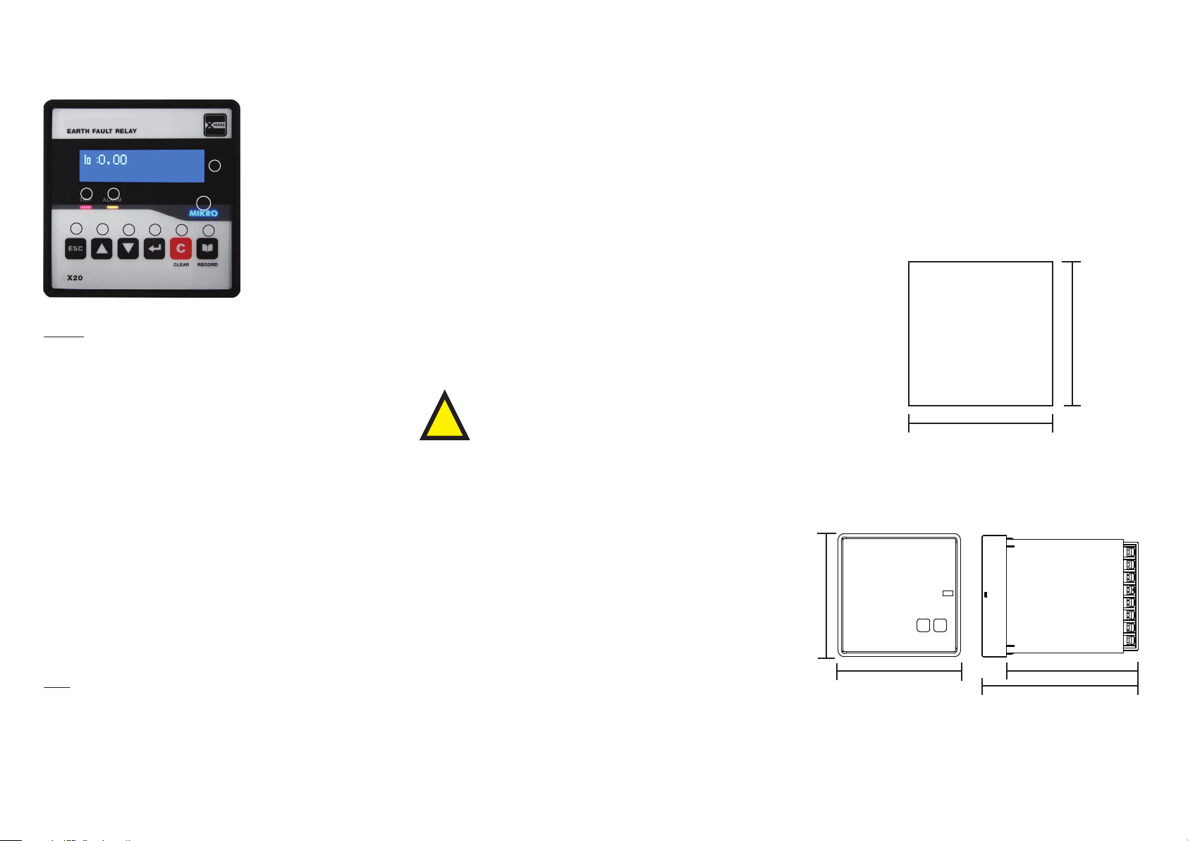
A Brief Overview
a) Trip LED Indication
b) Alarm LED Indication
c) 2x16 LCD Display
d) “ESC” Button
e) “UP” Button
f) “DOWN” Button
“ENTER” Button
g)
h) “CLEAR” Button
i ) “RECORD” Button
j ) AUX LED Indication
Keypad
Up, Down, Enter and Esc are used to navigate through the menus and
adjust the settings.
ESC : To exit from menus, submenus or to cancel setting value
change. Press and hold for 1.5 seconds to return to default
display from any submenu.
UP : Scroll up the menus or increase setting value.
Down : Scroll down the menus or decrease setting value.
Enter : To enter submenus or to conrm setting value change.
1. General Description
Mikro X20 is designed to provide protection of one non-directional
earth-fault element. This element is connected to protection current
transformer that has 5A rated CT on secondary part. `
Mikro X20 provides the user with 2x16 character LCD for displaying its
various measurement parameter such as: Current Measurement, Fault
Records, Event Records, Settings and others.
The relay extends its connectivity by adopting the Modbus-RTU protocol. Through the use of RS485 standard protocol, the user will be able
to network the relay with other slave device that links to a central
monitoring station.
Mikro X20 provides 2 congurable output relays that can be activated
by any of the protection functions available in the relay. There is another output relay which is used for internal fault indication. Besides that,
Mikro X20 also provides 1 conguration logic input for various
functions.
2. Thing to be Caution
The X20 should be installed, operated, serviced and
a) Before power up the X20, make sure auxiliarry voltage supply is not
out of the range given in connection diagram (85 - 265 VAC or 110 - 370
VDC).
b) Make sure no high voltage inject into terminal 15, 16, 17, 18, 19 and
20.
maintained only by qualied personnel. No responsiblility
is assumed by the manufacturer for any consequences
!
arising out of the use of this material.
4. Installation Guide
Before installing the X20, please ensure that the environment
meets the following conditions:
- Operating temperature: -5°C to +55°C
- Humidity: 56 days at 93%, 40°C non-condensing
- Dust free environment away from electrical noise and radiation.
5. Mounting
Insert the X20 through a 91mm x 91mm switch-gear panel as
shown below:
Panel
Cutout
91mm +/- 0.5mm
91mm +/- 0.5mm
6. Dimension
Clear : To reset tripping, reset latched relay. If “CLEAR” Scroll is enabled
(under Congurations->Display menu) and during alarm status,
it can be used to scroll through Earth Fault settings, and to
return to default display from any submenu by pressing and
holding for 1.5 seconds.
c) If LCD display and AUX LED not turn On after power up X20, please
stop using it and contact the manufacturer for service.
d) Anything crack on the casing, please stop using it and contact the
manufacturer.
96mm
Front
View
Side
View
3. Things include in Packing Box
Record : To display alarm records or successive records just press
Record button again.
LEDs
Trip LED : Indicates tripping
Alarm LED : Blinks to indicate non acknowledge alarm (or tripping).
Steady on when the alarm is acknowledged by pressing
any button.
a) 1 x X20 Protection Relay
b) 2 x Black Brackets
c) 1 x X20 Quick Reference Guide Hardcopy
105mm
96mm
125mm
* For more detail information, please download full set of X20
user manual from http://itmikro.com/Contents/view/122
website.
Page 2
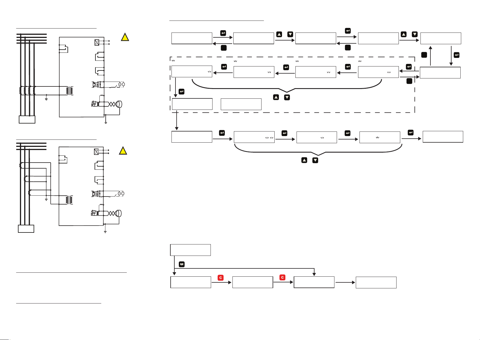
7. Connection Diagram
5A Secondary CT with 3 phase 4 wires
L1
L2
L3
N
9
IRF
Contact
10
R3
11
X20
15
5A
COM
16
LOAD
5A Secondary CT with 3 phase 3 wires
L1
L2
L3
9
IRF
10
Contact
11
R3
X20
15
5A
16
COM
LOAD
1
Uaux
2
3
Trip Contact
4
R1
5
6
R2
7
8
24 Digital Input 1
23
RP
20
Termination Resistor
P+
19
N-
18
17
GND
Communication
Cable Shield
1
Uaux
2
3
Trip Contact
4
R1
5
6
R2
7
8
24 Digital Input 1
23
RP
20
Termination Resistor
P+
19
N-
18
17
GND
Communication
Cable Shield
110 - 370 VDC
85 - 265 VAC
!
DANGER
*1
Series resistor 18k
Ohm, 2W required for
-
>94 Vac / 132 Vdc to
+
270Vac / 380Vdc
RS485
*2 Shorting terminal 18
and 20 for termination
for relays at 2 ends
110 - 370 VDC
85 - 265 VAC
!
DANGER
*1
Series resistor 18k
Ohm, 2W required for
-
>94 Vac / 132 Vdc to
+
270Vac / 380Vdc
RS485
*2 Shorting terminal 18
and 20 for termination
for relays at 2 ends
8. How to Change Setting in X20
There are two ways to change setting in X20 which are through RS485
Communication port.
Change setting through RS485 communication port
User can use X-series toolkit software to change setting in PC.
This X-series toolkit can be downloaded from website http://itmikro.com/Contents/view/122
Example of set date thorugh X20 front panel
Main Page
Io: 0.00
0 fourth digit start blinks
Enter password
0000
Password OK
Back to date page after
one second.
“p” shows password is unlock
Date p
xx/xx/xxxx
“Press”
Menu Page
1. MEASUREMENTS
ESC
0 Third digit start blinks
Enter password
0000
If entering wrong password
Password ERROR
or
Year number blinks
Date p
dd/mm/yyyy
or
3. CONFIGURATION
Goto
0 second digit start blinks
Enter password
0000
or
Press up or down button
to vary the number
Month number blinks
Date p
dd/mm/yyyy
Press up or down button
to vary the number
or
9. How to clear fault alarm
The following ow chart shown an example on how to clear fault
alarm:
Main Page
Io: 0.00
“Press”
“If no fault alarm”
Alarm Page
Rly latch 1/2
R1
“Press”
tIo> trip 1/1
12.3A
No alarm
3.1 Op Parameter
ESC
0 rst digit start blinks
or
Goto
Enter password
0000
ESC
“ If display does not show letter P at right top
corner, then user is required to key in password
for changing setting. The factory default
password is set as 0000”
Day number blinks
Date p
Back to main page after
few second.
Io: 0.00
dd/mm/yyyy
Save Data
3.3 Date & Time
ESC
Date
xx/xx/xxxx
Date p
xx/xx/xxxx
Change setting through X20 front panel
User must unlock the password rst then only allow to change the
setting. The default password for X20 is “0000”. The following ow
chart shown an example on how to change date:
* For more detail information, please download full set of X20
user manual from http://itmikro.com/Contents/view/122
website.
 Loading...