

Mikro X10 User Manual
X10 Earth Leakage Relay Quick Reference Guide
g
j
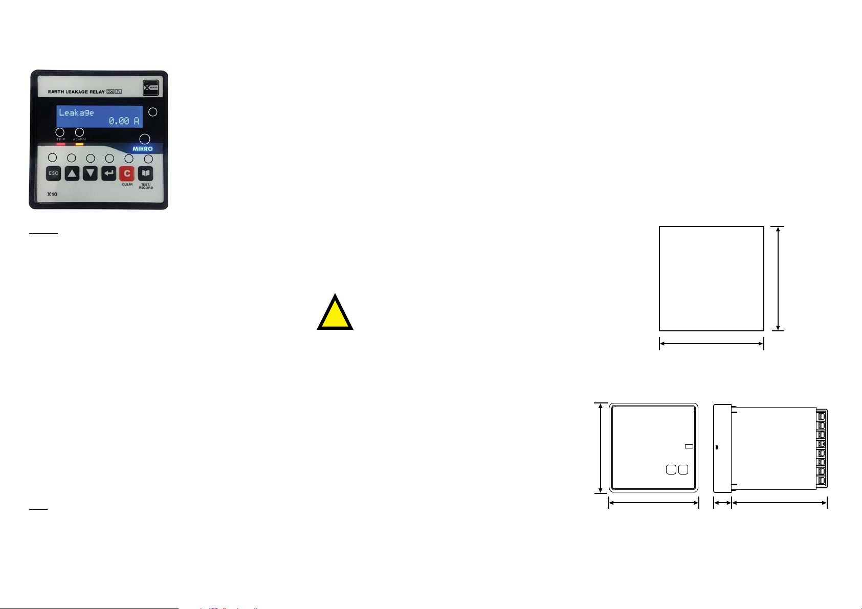
A Brief Overview
a) Trip LED
b) Alarm LED
c) 2x16-digit LCD with
c
a
b
d
e
f
Keypad
UP, DOWN, ENTER and ESC keys are used to navigate through the
menus and adjust the settings.
ESC :
UP :
DOWN :
ENTER :
CLEAR :
TEST/ :
RECORD
To exit from menus, submenus or to cancel the setting
value change. Press and hold for 1.5 seconds to return to
the default display from any submenu.
Scroll up the menus or increase the setting value.
Scroll down the menus or decrease the setting value.
To enter submenus or to conrm the setting value change.
To clear/reset the user resettable alarms. When the alarm
record is empty and the “CLEAR” Scroll is enabled (under
Congurations->Display menu), it can be used to scroll
through the protection settings. To return to the default
display from any submenu press and hold for 1.5 seconds.
To display the alarm records. To display successive records,
press the RECORD key again. If there’s no alarm press and
hold for 5 seconds to run the test function.
h
i
backlight display
d) “ESC” key
e) “UP” key
f) “DOWN” key
g) “ENTER” key
h) “CLEAR” key
i) “TEST/RECORD” key
j) Mikro logo and power
on indicator
1. General Description
Mikro X10 is an earth leakage relay with built-in advanced
features and functions for leakage protection, programmable
input and output control function, remote monitoring and etc. It
works together with Mikro’s zero-phase current transformer
(ZCT) to perform the protection function.
The relay provides the user with a 2x16 character LCD for
real-time display of leakage current, fault records, event record,
alarm record, various internal settings and etc.
The relay extends its connectivity by adopting the Modbus-RTU
protocol. Through the use of RS485 standard protocol, the user
will be able to network the relay with other slave devices, linked
to a central monitoring station.
The relay provides 2 programmable output contacts. There is
another output contact which is used for the relay’s internal fault
indication. Besides that, it also provides 1 conguration logic
input for various functions.
2. Precaution
Please observe the following safety precautions
before and during the installation of the relay :
!
Only competent and trained personnel should install, operate,
service and maintain this device.
Disconnect ALL power sources to the relay before performing
installation, inspection, tests and maintenance.
Do not perform megger, hi-pot or any high voltage stress test
with the relay connected to the system.
Install in a suitable enclosure where relay connections are
inaccessible with sucient clearance from other live parts.
Please note that incorrect installation may impair the operation
or even damage the relay. There is no user servicable part in the
relay. Tampering with it may damage the relay, result in injury
and also voiding any warranty.
3. Things included in the packing box
a) 1 x X10 protection relay
b) 2 x black colour retainer clips
c) 1 x X10 quick reference guide
4. Installation Guide
Before installing the relay, please check that the environment
meets the following conditions:
- Operating temperature: -5°C to +55°C
- Humidity: 5% to 95%, non-condensing
- Dust free environment away from electrical noise and radiation.
5. Mounting
Insert the relay through a 91mm x 91mm cutout on a switch-gear
panel as shown below:
Panel
Cutout
91mm +/- 0.5mm
91mm +/- 0.5mm
6. Dimension
96mm
Front
View
Side
View
LEDs
Trip LED :
Alarm :
LED
Indicates tripping.
Blinks to indicate unacknowledged alarm and continuously ON when the alarm is acknowledged by pressing
any key.
Before power up the relay, make sure the auxiliary voltage
supply is within the specication of 85 - 265 VAC or 110 - 370 VDC.
After powering up the relay, please ensure the LCD display and
the AUX Led indicator are turned on.
96mm
* For more details, please download the full set of X10 user
manual from the http://itmikro.com/contents/view/122
webpage.
20mm
105mm
7. Change Setting
There are two ways to change setting in X10.
Method 1: Change setting through rear RS485 communication port
User can use X-series toolkits software to change setting in PC.
The toolkits can be downloaded from website http://itmikro.com/contents/view/122
Method 2: Change setting through relay front panel
User must unlock the password rst then only allow to change the setting. The default password is “0000”.
The following ow chart shown an example on how to change date:
Main Page
Leakage
0.00 A
0 fourth digit start blinks
Enter password
0000
“Press”
Menu Page
1. MEASUREMENT
ESC
Enter password
0000
0 Third digit start blinks
or
3. CONFIGURATION
Goto
0 second digit start blinks
Enter password
0000
3.1 OP Parameter
ESC
0 rst digit start blinks
Enter password
0000
or
3.2 Date & Time
Goto
Date
xx/xx/xxxx
ESC
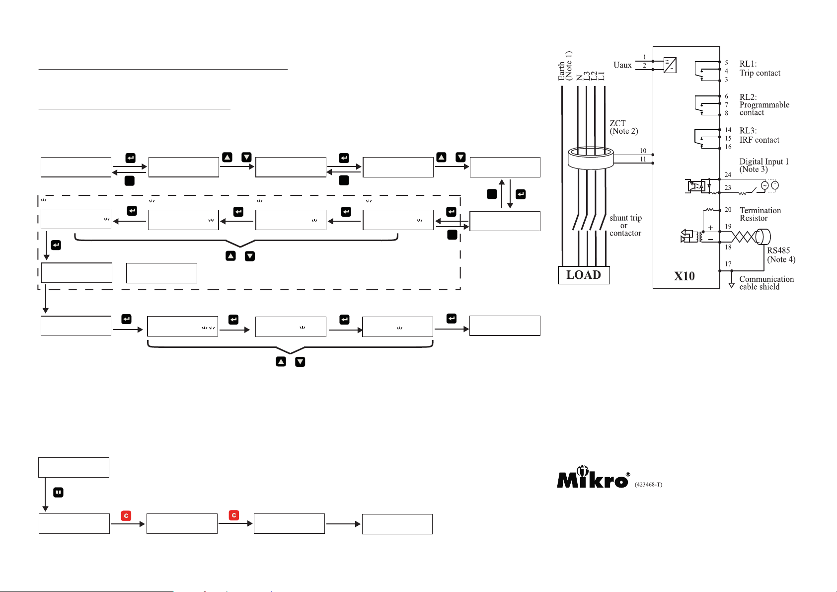
9. Connection Diagram
+
ESC
“ If display no show letter P on right top corner,
then user is required to unlock password for
changing setting. The factory default password is
set as 0000”
Day number blinks
Date p
xx/xx/xxxx
or
Save Data
Date p
xx/xx/xxxx
Password OK
Back to date page after few second.
“p” shows password is unlock
or
Date p
xx/xx/xxxx
If entering wrong password
Password ERROR
Year number blinks
Date p
xx/xx/xxxx
or
Press up or down button
to vary the number
Month number blinks
Date p
xx/xx/xxxx
Press up or down button to vary the number
8. Alarm Record
Alarms are divided into two catogories: user resettable and non-resetable types.
For the user non-resettable type, the alarm is self reset by the relay once the alarm condition is removed.
For the user resettable type, the user must ensure the cause of the alarm is removed before the the alarm can be cleared.
The following ow chart shown an example on how to clear fault alarm:
Main Page
Leakage
“Press”
Alarm Page
Relay 1 1/2
On
* For more detail information, please download full set of X10 user manual from http://itmikro.com/contents/view/122 webpage
0.00 A
“Press”
In1 Trip 1/1
50mA
No record
Back to main page after
few second.
Leakage
0.00 A
Note 1 :
Note 2 :
Note 3 :
The EARTH wire must not pass through the ZCT.
The relay must work together with Mikro’s ZCT.
External series resistor 18k ohm, 2W is required for input
voltage greater than 94Vac or 132Vdc
Note 4 :
Short terminals 18 and 20 for communication data lines
termination. Applicable only for relays located at the head
and tail ends of the communication lines.
No. 1, Jalan TP7/7, Sime UEP Industrial Park
40400 Shah Alam,
Selangor Darul Ehsan, Malaysia
Tel: +603-51927155
Fax: +603-51927166
Website: wwwitmikro.com
E-mail: salas@itmikro.com
 Loading...