

Mikro N302 User Manual
AUXTRIPDELAY
TEST RESET
ms
EARTH LEAKAGE RELAY
N302
N302 Earth Leakage Relay User’s Guide
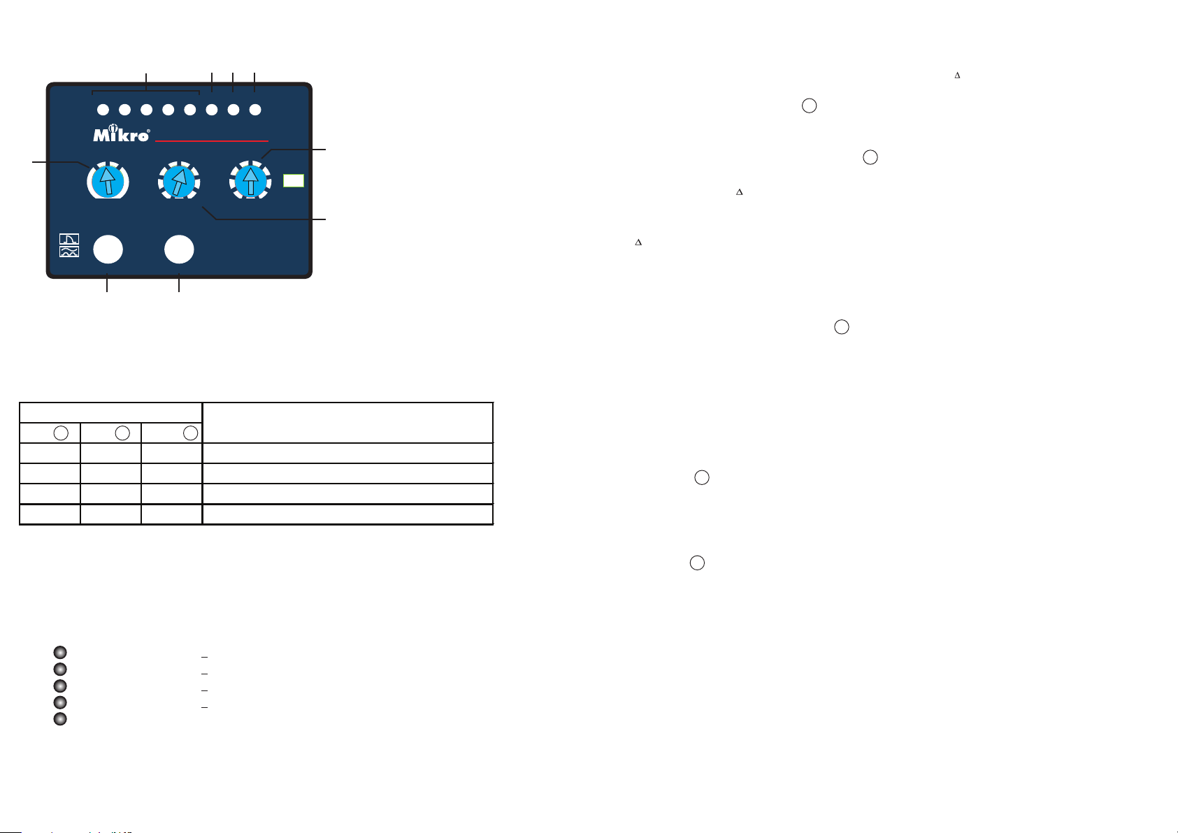
Indicator
c
b
100
50
150
250
a
a - Auxiliary power indicator
b - Trip status indicator
c - Trip start indicator
e
350
500
1000
3000 INST
d - Leakage current indicator
e - Time delay selector
f - Sensitivity selector
f
g - Sensitivity multiplier selector
h - Reset button
d
80%60%40%20%10%
x10
x100
g
x1
75
50
100
125
mA
150
300 30
200
250
2. Sensitivity Adjustment
The N302 features 2 rotary selector switches for sensitivity ( I n) setting:
( i ) 9- position sensitivity selector oers setting range of 30mA, 50mA, 75mA, 100mA,
125mA, 150mA, 200mA, 250mA and 300mA.
( ii ) 3- position sensitivity multiplier selector switch oers selection of 1x, 10x and 100x.
Example 1: To set I n = 100mA
Step 1: Set sensitivity selector = 100mA
Step 2: Set sensitivity multiplier selector = 100x
I n = 100mA x 100 = 10A
f
g
i - Test button
i
h
1. Light Indicator
( i ) Status Indicators
a
Aux Trip Delay
b
c
O O O No auxiliary power
On O O System normal, no tripping
On O On Trip start, time delay countdown started
On On O Earth leakage tripped
( ii ) Leakage Indicators
a) The earth leakage indicators indicate the amount of leakage current detected and are
expressed as percentage of the set current.
10% - leakage current > 10% of set current
20% - leakage current > 20% of set current
40% - leakage current > 40% of set current
60% - leakage current > 60% of set current
80% - leakage current > 80% of set current
Status
3. Tripping Delay Time Adjustment
- The 9 position time delay selector provides additional delay for fault
e
discrimination.
- Selectable delay are: Instantaneous (no delay), 50ms, 100ms, 150ms, 250ms,
350ms, 500ms, 1s and 3s.
4. Push Button Operations
( i ) Reset Button
- The reset button is for resetting the light indicator and the trip contact after an earth
leakage tripped.
- To reset, press the reset button once.
( ii ) Test Button
- Press and hold the test button for 3s to simulate an earth leakage trip condition.
h
i
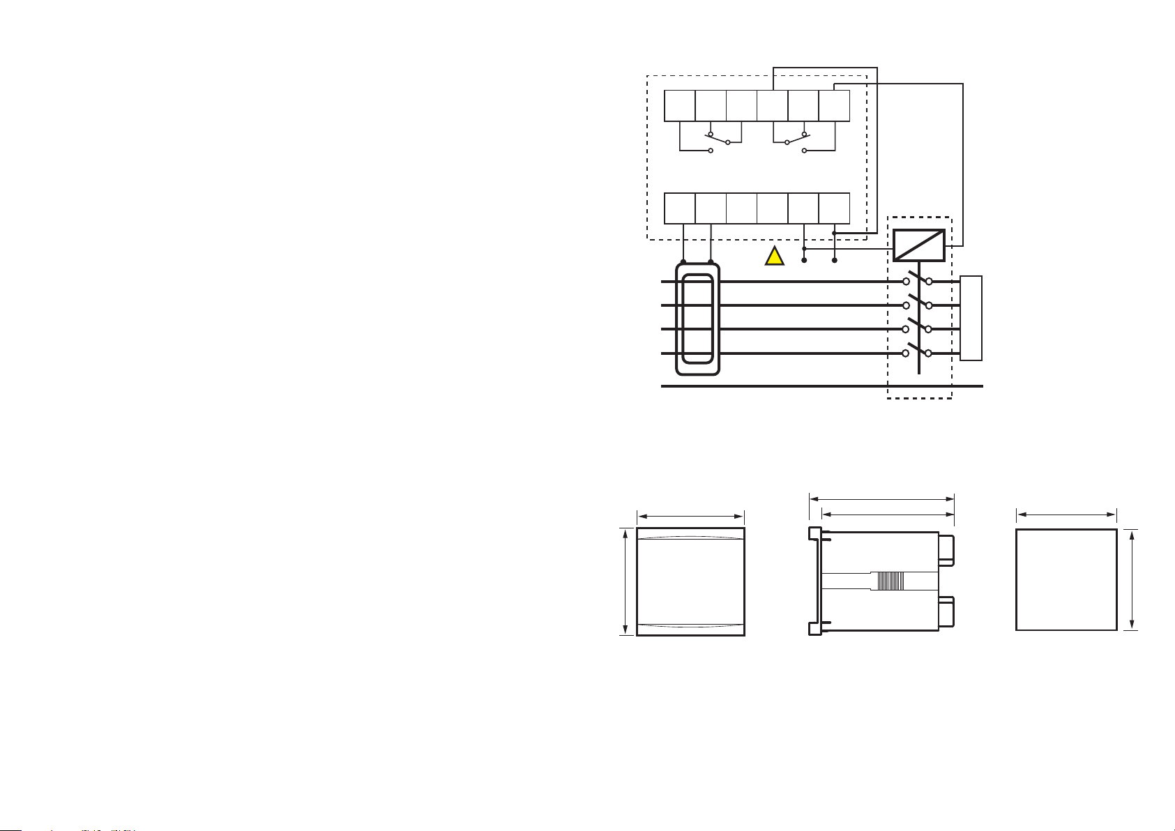
5. Output Contact
( i ) Trip Contact
- This is a latching type contact. It operates when tripped.
b) When the N302 detects absence of zero-phase current transformer (ZCT) connection, it will
blink the leakage indicators.
( ii ) Safety Contact
- Contact energized when supply is connected and the relay is functioning
normally.
6. Technical Data
Aux
ZCT
7. Connection Diagram
Auxiliary Supply
N302-240AD............................................ 85 ~ 265 VAC or 110 ~ 370 VDC
Supply frequency.................................. 50Hz or 60Hz
VA rating................................................... Less than 3 VA typical
Setting Ranges
Sensitivity Setting.................................30mA, 50mA, 75mA, 100mA, 125mA, 150mA,
200mA, 250mA, 300mA, 500mA, 750mA, 1A,
1.25A, 1.5A, 2A, 2.5A, 3A, 5A, 7.5A, 10A, 12.5A, 15A,
20A, 25A and 30A.
Time delay setting.................................Instantaneous, 50ms, 100ms, 150ms, 250ms, 350ms,
500ms, 1000ms and 3000ms.
Inputs
Sensor........................................................ ZCT*
Output Contact
Rated Voltage......................................... 250 VAC
Continuous carry................................... 5A (cos = 1.0)
Contact material.................................... Silver alloy
Operating time.......................................15ms max
Expected electrical life........................100,000 operations
Expected mechanical life................... 5 million operations
N 302
1
Safety Contact
7 8 9 10
L1
L2
L3
N
PE
*The EARTH wire must not pass through the ZCT
8. Case Dimensions
72 mm
Trip Contact
!
DANGER
11
12
62 3 4 5
LN
LOAD
97 mm
89 mm
68.0 ± 0.5 mm
Indicators
Auxiliary supply..................................... Green LED indicator
Time delay............................................... Red LED indicator
Trip............................................................. Red LED indicator
Leakage current.................................... 5 red lights for leakage levels
Mechanical
Mounting.................................................. Panel mounting
Front panel............................................... 72x72 mm
Approximate weight............................. 0.5 kg
72 mm
Side
Front
68.0 ± 0.5 mm
 Loading...