

Mikro N202 User Manual
O O O No auxiliary power supply.
On O O System normal mode. No tripping.
N202 IDMT Earth-Fault Relay User’s Guide
AUXI>>I>
TEST RESET
I
0.1A
0.5A
2A
1.5A
1A
TM
0.05
0.1
0.2
0.3
0.4
0.5
0.6
0.7
0.8
0.9
1.0 I X1
X2
X4
X6
X8
X10
IDMT EARTH FAULT RELAY
N202
a
b
c
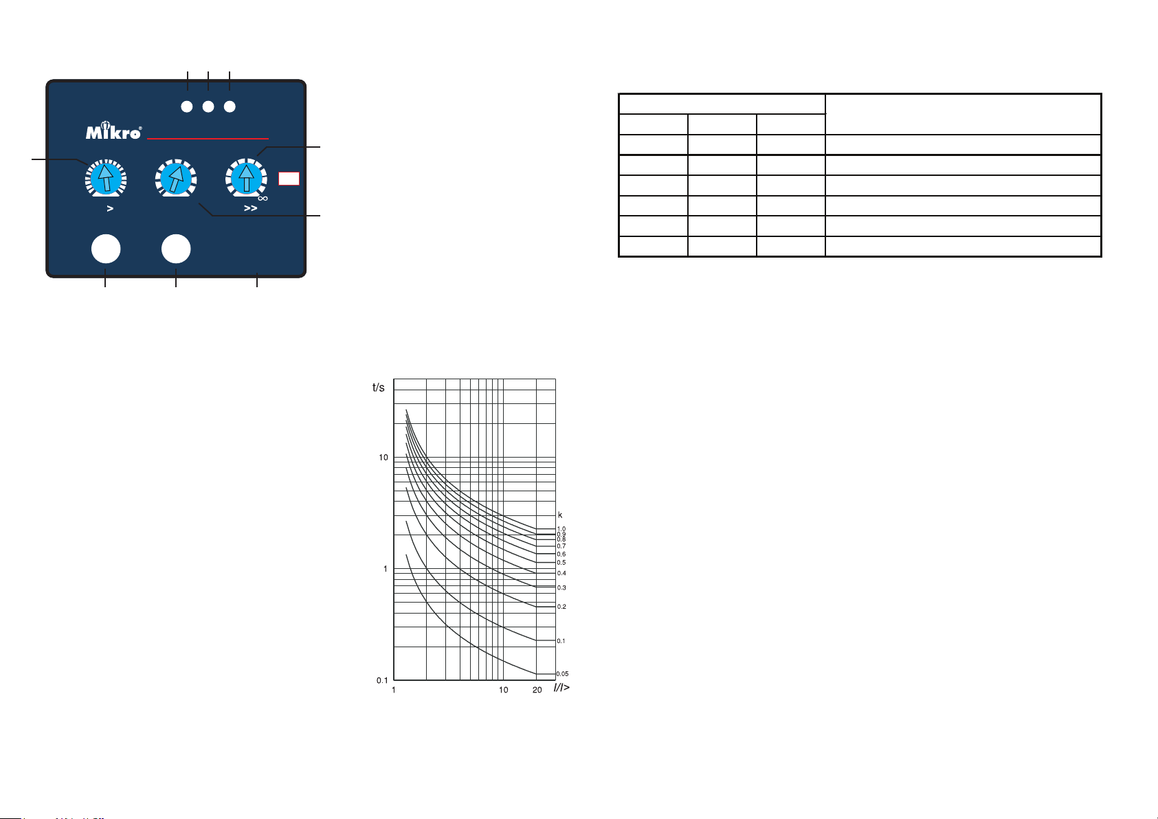
a - Low-set start/trip status indicator
2. Light Indicators
The light indicators display the status of the system.
b - High-set start/trip status indicator
c - Auxiliary power supply indicator
h
f
d - Test button
e - Trip reset button
f - Earth-fault low-set adjustment
g
g - Delay time adjustment
h - Earth-fault high-set adjustment
d
e
f
TECHNICAL DATA
1. Current and Time Adjustments
Earth-fault Low-set Current (I>) Adjustment
- This adjustment is for setting the minumum earth-fault
current for tripping with time delay.
- The setting range is between 0.1A to 2A
Indicator
AUX I> I>>
Status
On Blink O Earth-fault low-set start.
On On O Earth-fault low-set tripped.
On O Blink Earth-fault high-set start.
On O On Earth-fault high-set tripped.
3. Push Buttons
Reset Button
- The reset button is for resetting the light indicators (I> or I>>) after an earth-fault tripping
has occured.
- To reset, press the reset button once.
Test Button
- Test button is for checking the relay operation.
- Push and hold the test button, I> and I>> LEDs start blinking then LEDs turn On and relay
contacts will be activated after 3s.
Earth-fault High-set Current (I>>) Adjustment
- This adjustment is for setting the instantaneous tripping
current due to an earth-fault.
- The setting range is between 1x to 10x of the earth-fault
low-set setting value.
I>> = a x I> (a= 1 to 10)
- This high-set feature can be disabled by setting the
tripping current to innity (∞).
Time Delay (TM) Adjustment
- The time multiplier is for setting the normal inverse
time/ current characteristic (IDMT) as according to
BS142.
- The setting range between 0.05 to 1.0 .
IDMT Normal Inverse Curve
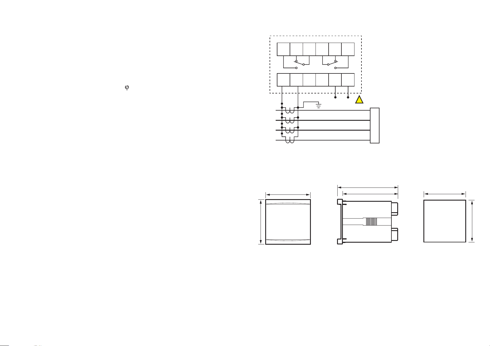
4. Trip Contacts
There are two set of tripping contacts namely, R1 and R2.
R1,R2 - Manual Reset Type
- These contacts is activated during an earth-fault trip. The contacts remain activeted
regardless of the removal of fault current. This relay can only be reset by pressing the
“RESET” button.
5. Electrical Specication
Aux
7. Connection Diagram
Auxiliary Supply
N202-240AD............................................ 85 ~ 265 VAC or 110 ~ 370 VDC
Supply frequency.................................. 50Hz or 60Hz
VA rating................................................... 3 VA typical
Trip Contact
Rated Voltage......................................... 250 VAC
Continuous carry................................... 5A (cos = 1.0)
Expected electrical life........................100,000 operations
Expected mechanical life................... 5 million operations
Setting Ranges
Low-set (I>)..............................................0.1A to 2.0A (2% to 40%)
Low-set delay time (TM).....................0.05 to 1.0
High-set (I>>)......................................... I> to 10x I> or disable
High-set delay time (t>>).................. Instantaneous
Indicators
Auxiliary supply..................................... Green LED indicator
Pick-up...................................................... Red LED indicator
Trip............................................................. Red LED indicator
COMNO NC
1
R1
7 8 9 10
L1
L2
L3
N
8. Case Dimensions
72 mm
COM NC NO
62 3 4 5
R2
12
11
N
N 202
L
DANGER
!
97 mm
89 mm
LOAD
68.0 ± 0.5 mm
6. Mechanical
Mounting.................................................. Panel mounting
Front panel............................................... 72x72 mm
Approximate weight............................. 0.6 kg
Side
Front
72 mm
68.0 ± 0.5 mm
 Loading...