

Mikro MK204A, MK203A User Manual
MK204A IDT Overcurrent Relay User's
Guide
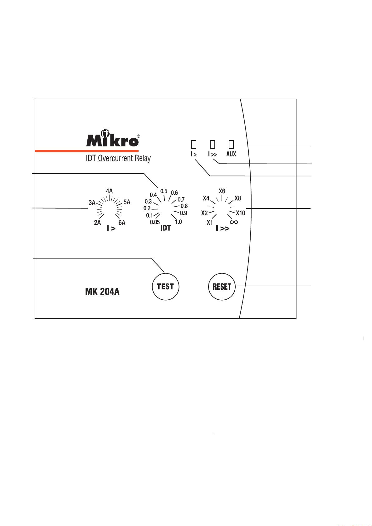
A BRIEF OVERVIEW
a
b
c
d
h
g
f
e
a - Auxiliary power supply indicator
b - High-set start/trip status indicator
c - Low-set start/trip status indicator
d - Overcurrent high-set adjustment
e - Trip reset button
f - Test button
g - Overcurrent low-set adjustment
h - Time multiplier adjustment
TECHNICAL DATA
1. Current and Time Adjustments
Overcurrent Low-set Current (l>) Adjustment
• This adjustment is for setting the minimum overcurrent
for tripping with time delay.
• The setting range is from 2A to 6A.
Overcurrent High-set Current (l>>) Adjustment
• This adjustment is for setting the instantaneous tripping
current due to an overcurrent.
• The setting range is from 1x to 10x of the overcurrent
low-set setting value.
l>> = a x l>, a = 1 to 10
• This high-set feature can be disabled by setting the
tripping current to infinity ( ' )
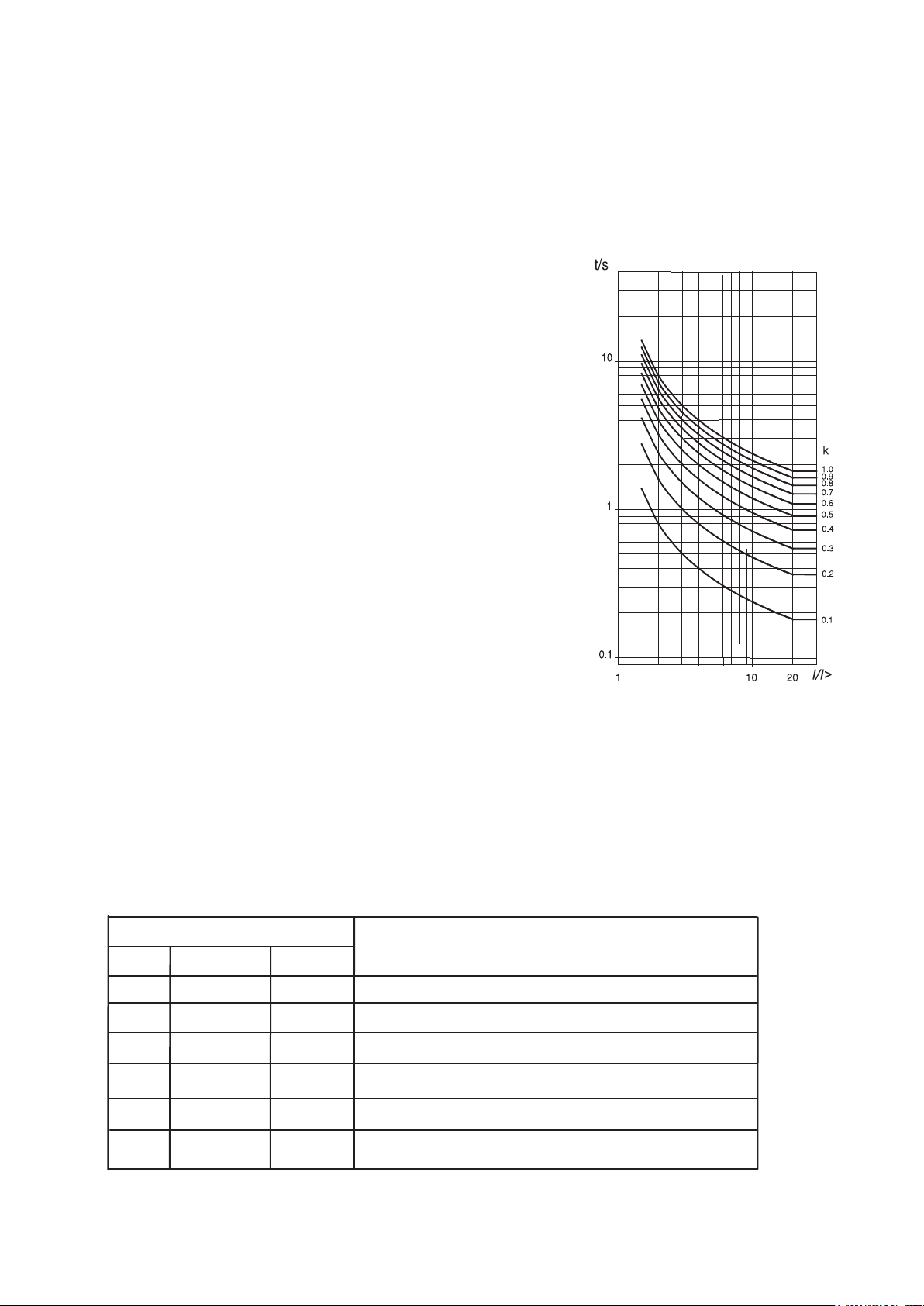
Time Multiplier (IDT) Adjustment
• The delay timing adjustment is for selecting different
delay curve as shown in figure 1.
2. Light Indicators
The light indicators display the status of the system.
• The setting range is from 0.05 to 1.0.
Figure 1: IDT Inverse
Indicator
AUX l> l>> Status
Off Off Off No auxiliary power supply.
On Off Off System normal mode. No tripping.
On On Off
On
On Off On
On Off Blink Overcurrent high-set tripped.
Blink Off Overcurrent low-set tripped.
Overcurrent low-set start.
Overcurrent high-set start.
 Loading...