

Mikro DPM380 User Manual

v1.0
Digital Power Meter User Manual
DPM380
No.1, Jalan TP7/7, Sime UEP Industrial Park,
40400 Shah Alam, Selangor, Malaysia.
Website: www.itmikro.com
Tel: +(603)51927155 Fax: +(603)51927166

HAZARD CATAGORIES AND SPECIAL SYMBOL
Read all instruction carefully and check the device before
installing or service it. The following safety alert symbol may
appear throughout this manual or on device to warn any
potential hazards or to call for attention.
PLEASE NOTE
The power meter should be installed, operated, serviced and
maintained only by qualifi ed personnel. No responsibility is
assumed by the manufacturer for any consequences arising
out of the use of this material.
DISCLAIMER
Mikro shall not be liable for errors contained herein including
any incidential and/or consequential damages arising from
the use of this material. Mikro also reserves the right to vary
the product from that described in this material without prior
notice.
COPYRIGHT
The licensed software contaioned in the product is proprietary
software owned by Mikro or its third party suppliers and shall
be used solely in connection with the product.

BEFORE YOU BEGIN
• Apply appropriate personal protective equipment and
follow safe electrical work practices.
• NEVER work alone.
• Turn-off all power supplying the power meter and the
equipment in which it is installed before working on it.
• Always use a properly rated voltage sensing device to
confi rm that all power is off .
• Before closing all covers and doors, carefully inspect the
work area for tools and objects that may have been left
inside the equipment.
• NEVER bypass external fusing.
• NEVER open circuit a CT; use the shorting block to short
circuit the leads of the CT before removing the connection from the power meter.
• Before performing hi-pot testing on any equipment in
which the power meter is installed, disconnect all input
and output wires to the power meter. High voltage testing may damage electronic components contained in
the power meter.
• The power meter should be installed in a suitable electrical enclosure.
Failure to follow this instruction may result in serious
injury.

CONTENTS
1. Introduction
1.1.Content of box
1.2.Part of power meter
2. Installation Guide
2.1.Precautions
2.2.Mounting
2.3. Wiring
3. Meter parameters
4. Display and Buttons
1
1
2
4
4
4
7
11
12
5. Function
6. Setting up
6.1.Access programming mode
6.2.Setup CT ratio
6.3.Setup PT ratio
6.4.Neutral current
6.5.Setup communication confi guration
6.6.Demand setting
6.7.System setting
6.8. Reset all energy register
6.9. Reset demand register
6.10. Reset maximum & minimum value
13
15
15
16
17
18
19
20
21
22
23
24
6.11. Remote set
6.12. Scroll mode setting
25
26

6.13. Scroll delay setting
27
6.14. Reset Hour on register
6.15. Backlight setting
6.16. Exit from programming mode
6.17. Setup new password
7. Specifi cations
8. Modbus table
9. Maintenance and troubleshooting
10. Dimensions
28
29
30
31
33
36
50
51
11. Appendix
11.1. Demand calculation
11.2. Data read format from modbus
53
53
54

FIGURES
1. Parts of power meter
2. Recommendation cut-out
3. 3-phase 4-wire system with 4 CTs
4. 3-phase 4-wire system with 3 CTs
5. 3-phase 3-wire with 3CTs and 3VTs
6. 3-phase 3-wire with 2CTs and 3VTs
7. Menu map for the normal mode
8. Flow map for the programming mode
2
4
7
8
9
10
13
14
TABLE
1. Parts list
2. Location and part label
3. Model information
4. Specifi cation
5. Data length nomenclature
6. Device and communication register
7. Operation data registers
8. Setting data registers
1
2
3
33
36
37
37
49

1.Introduction
Thank you for purchasing the DPM380 Digital Power Meter.
This multifunction power meter measuring the following
parameters:
• True RMS phase voltage ( L-N )
• True RMS line voltage (L-L )
• True RMS phase and neutral current
• Active, reactive and apparent power
• Total active, reactive and apparent energy
• Total and displacement power factor
• Frequency
• Voltage and current total harmonic distortion (THD)
• Demand and maximum demand for total active, reactive
and apparent power
• Maximum and minimum phase and line voltage
• Maximum and minimum phase and neutral current
• Maximum and minimum total active, reactive ad apparent power
1.2. CONTENT OF BOX
Upon opening this box, you should fi nd the following item
shown in table 1:
No Description Quantity
1 DPM380 power meter 1
2 Retainer clip 2
3 Quick guide 1
Table 1 : Parts list
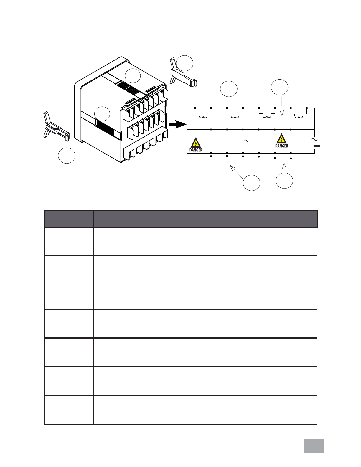
1.3. PARTS OF POWER METER
5
6
1
CURRENT INPUTS ... / 5A (6A MAX.)
5
6
I1 I2 I3 In
1
VOLTAGE INPUT L-N 300V MAX. 50/60Hz
Category III
3
2
S2 S2
L1
S1S1
11
109
1615
L2
4
57 8
S1
Modbus RTU RS485
Gnd
L3 Ln
Figure 1 : Parts of power meter
4
Table 2: Location and part label
Number Part Description
1 Current inputs Current metering connec-
tions.
2
6
S2
1312
-
-
AUX
S1
14
+
90V~415VAC
50/60Hz
100V~300VDC
3VA
20191817
+
S2
3
2 RS485 port The RS485 port is used for
communication with remote
monitoring and control
system.
3 Power supply
input
Connection to power the
meter
4 Voltage inputs Voltage metering connec-
tions.
5 Retainer clips Used to hold power meter
in place.
6 Retainer clips
slot
To slot in retainer clips in
place
2

Model Information
DPM380-415AD Auxiliary 90~415VAC or
100~300VDC; with Modbus
Table 3: Model information
3
2. Installation Guide
2.1. PRECAUTIONS
Before installing the power meter,please check that the
environment meets the following condition:
• Operating temperature -10 Celcius to +55 Celcius.
• Humidity 5% to 95%, non-condensing
• Dust free environmental away from electrical noise and
radiation
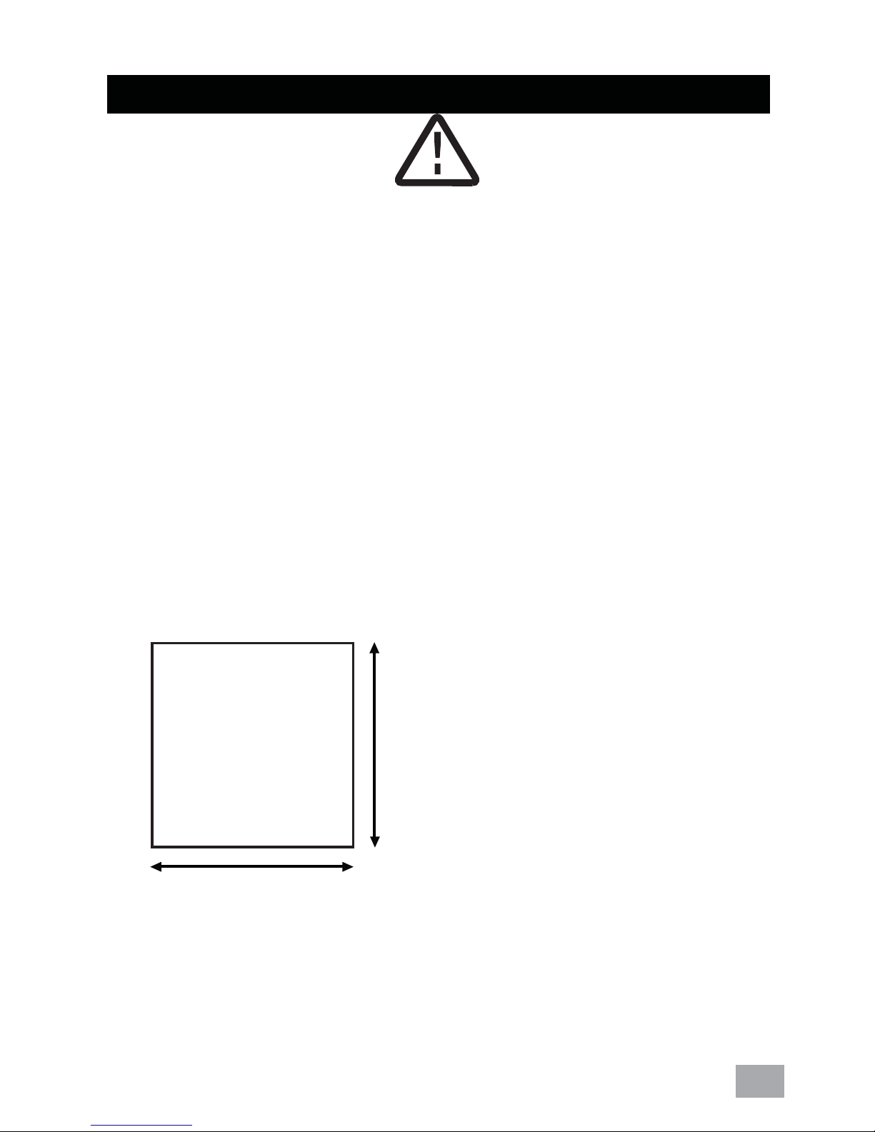
2.2. MOUNTING
a) Provide a cut out hole on the switchgear panel according
to the dimension below.
91 0.5mm
91 0.5mm
Figure 2:Recommended out-cut.
4

b) Insert the power meter through the hole and slide in the
retainer clip along the slots on left and right sides or bottom
and top sides of the power meter until the device is tightly
secured on the switchgear panel. The orientation of the
retainer clips is shown in fi gure 1.
The retainer clip can be removed by lifting the tab lightly at
the handle end.
c) Connect the metering voltage input, current input,
communcation and auxiliary according to the wiring schemes
shown in section 2.2 fi gure 3 to 6 on the next page.
d) The recomended wire size is as below:
• voltage input and auxiliary - AWG16~22
• current input - AWG12~18
• Modbus-RTU - AWG22 or thicker, shielded twisted pair
NOTE:
for CTs (S1 and S2).
Please make sure the power to the current metering input is totally shunted. Under no circumstances
can the CT connection be left open circuit. Use a
Polarity marks must be followed as shown
CT shorting block if necessary.
5
e) When connecting the power meter, please make sure the
polarity to the terminal is correctly aligned.
f) If the Modbus-RTU is used, it can be connected up to 32
devices in a daisy chain fashion and the cable total length
should not be more than 1000m.
NOTE:
the cable near sources of electrical noise. The
network cable sheild should be grounded at only
one end.
For Modbus-RTU connection, avoid running
6
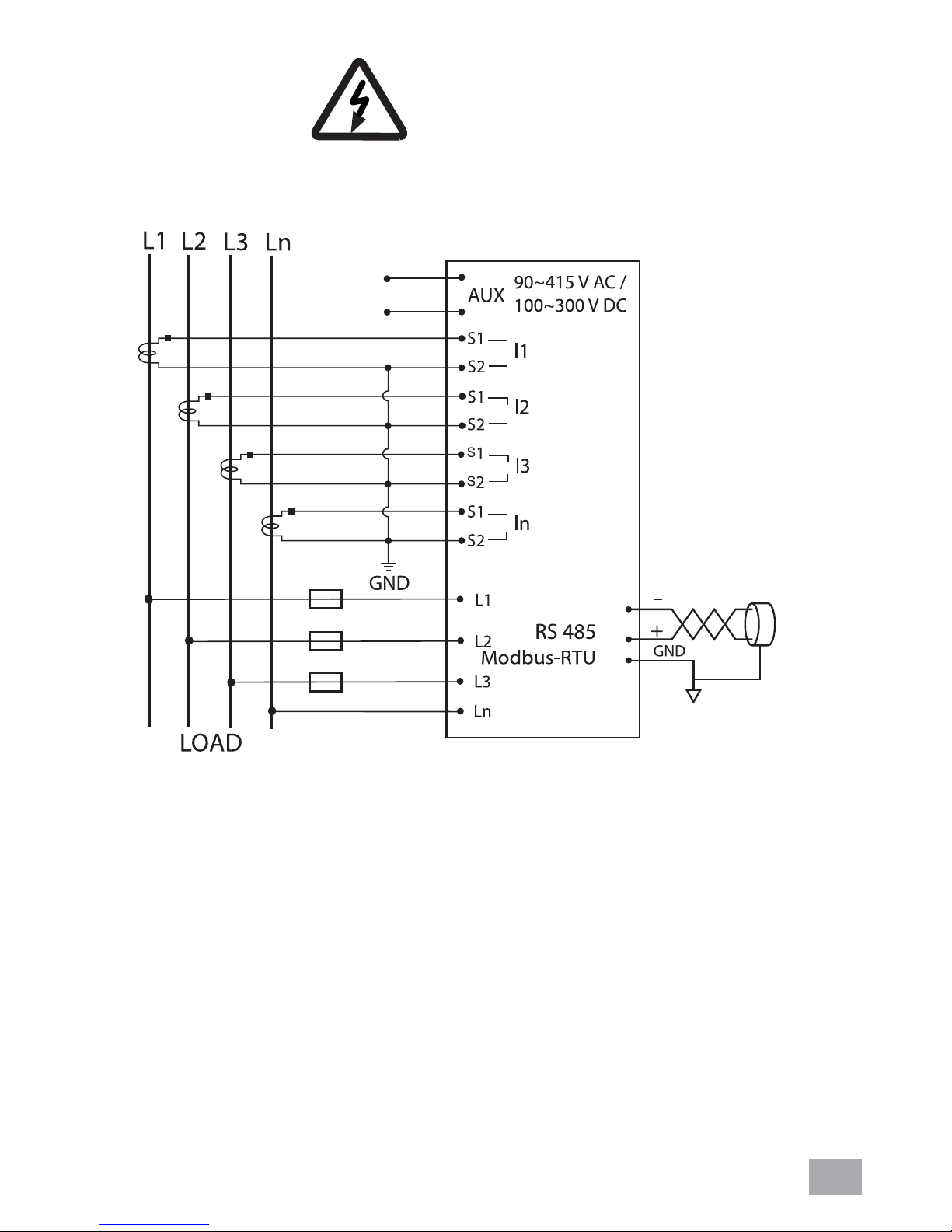
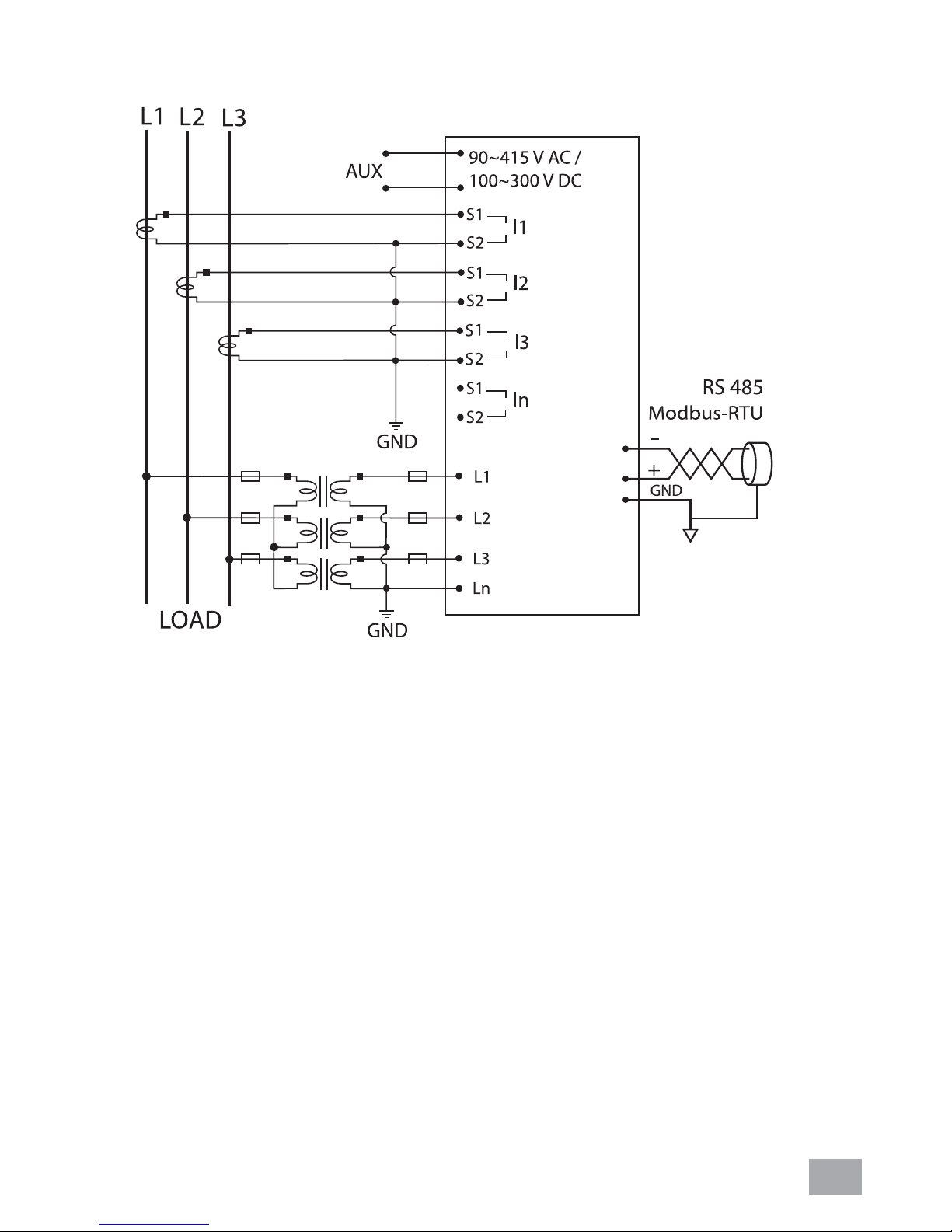
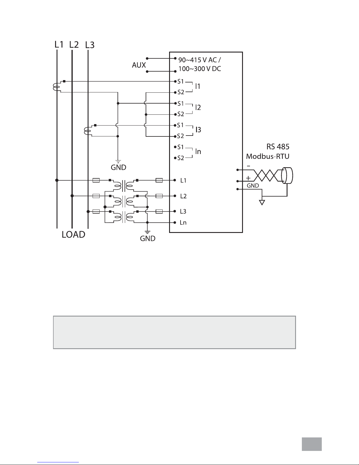
2.3. WIRING
19
20
1
2
3
4
5
6
7
8
15
13
16
17
18
14
12
Figure 3: 3 Phase 4-Wire System with 4CTs connection,
direct voltage input.
7

19
20
15
16
17
18
1
2
3
4
5
6
7
8
13
14
12
Figure 4: 3-Phase 4-Wire System with 3CTs connection,
direct voltage input.
NOTE: Neutral current measurement is based on the
vector sum of 3 CTs.
8
19
20
15
16
17
18
1
2
3
4
5
6
7
8
13
14
12
Figure 5: 3-phase 3-wire with 3CTs and 3VTs connection.
9
19
20
1
2
3
4
5
6
7
8
15
16
17
18
13
14
12
Figure 6: 3-phase 3-wire with 2CTs and 3VTs connection.
NOTE: I2 current measurement is based on the vector
sum of
2 CTs.
10

3. Meter parameters
Before commencing operation, the meter has to be set up. To
do this, the meter must be powered up by the meter control
power supply.
Under section 6, the following parameters should be reviewed
against the default value if necessary:
• CT ratio
• PT ratio
• Neutral current input
• Modbus-RTU setting
• Demand setting
• System setting
• Scroll mode setting and delay time
• Backlight setting
The fl ow maps for the meter is under section 5. It is guideline
for the user to fl ip to the desire window whether in normal
mode or programming mode.
11
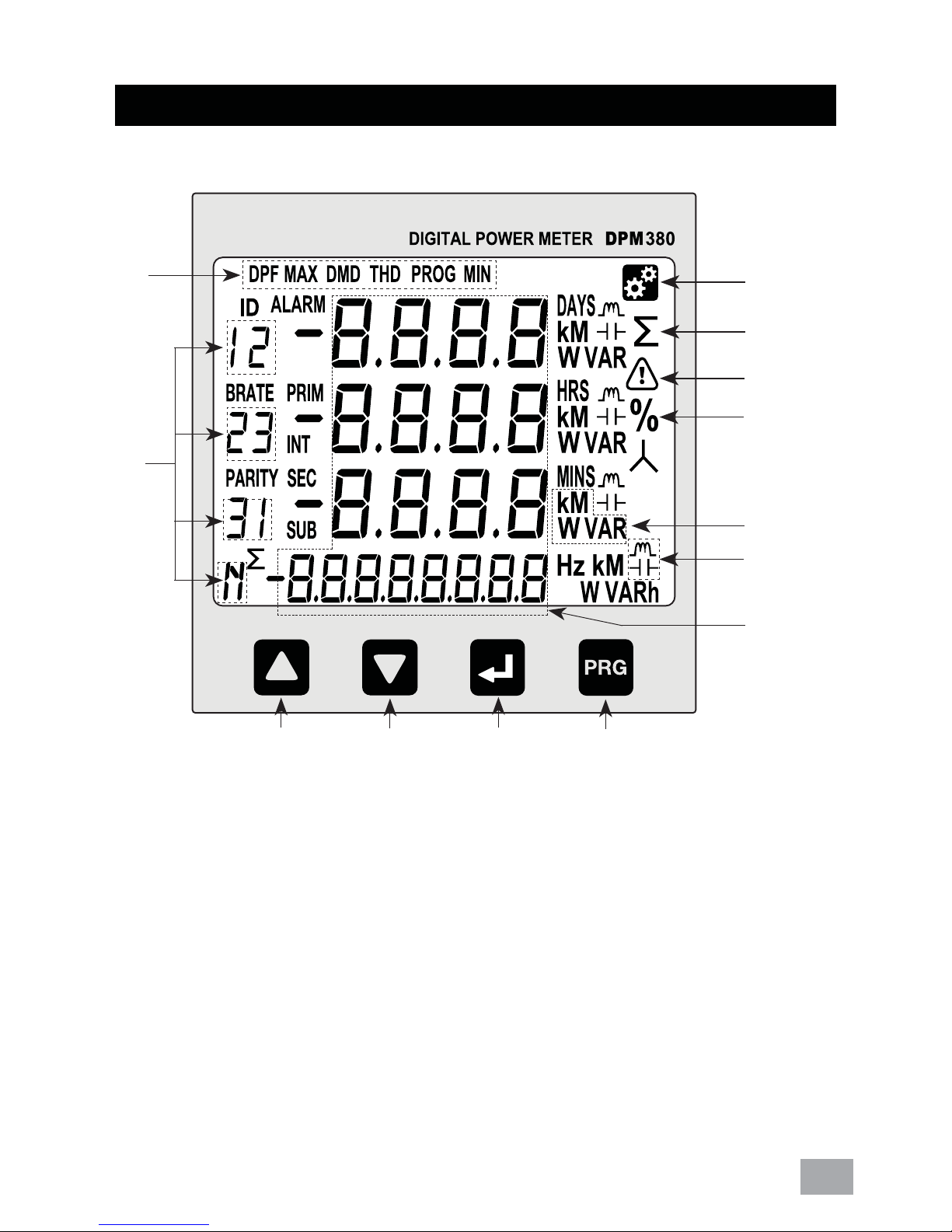
4. Display and Buttons
m
l
a
b
c
d
e
f
g
k
a. Setting Indicator h. ‘PROG’ button
b. Total Indicator i. ‘NEXT’ button
c. Alarm Indicator j. ‘DOWN’ button
d. Percentage Indicator k. ‘UP’ button
e. Unit Indicator l. Phase Indicator
f. Capasitive/Inductive Indicator m. Window Indicator
g. Digit Display
j
i
h
12
 Loading...