

Page 1

REVERSIBLE COMPACTOR
INSTRUCTION MANUAL
402-04504
We thank you for selecting Mikasa
Vibration Compactor. For your safe
and proper operation, please read
this manual and be always sure to
keep it ready for reference.
MVH-R60
MVH-120
MVH-150
Contentsof“DeclarationofConformity”
Pleasereferthe
ECDECLARATIONOFCONFORMITY
inthismanualaswell.
Original
Page 2

Page 3

5) model
MVH-R60 MVH-120GH MVH-120GR MVH-150GH MVH-150GR MVH-150D
6) Equipmen
t
item numbe
r
452726 452732
452733
452802 452806
452814
452810 452811
452772 452776
452778
452762 452758
7) Serial number
8) power source
cont. output
<max.output>
Honda GX120
2.1kW
<2.6kW>
Honda GX160
2.9kW
<3.6kW>
Robin EH17
2.9kW
<3.7kW>
Honda GX200
3.7kW
<4.1kW>
Robin EH25
4.7kW
<5.9kW>
Yanmer L48N
3.1kW
<3.5kW>
9) Measured
sound power
l
evel(dB)
104 107 106 107 107 107
10) Guaranteed
sound power
level(dB)
105 108 108 108 108 108
11) Max. Sound
pressure
level
(dB)
90 94 94 94 97 95
For serial number, please refer it on front page.
2) Manufacturer’s name and address.
3) Name and address of the person who keeps the
technical documentation.
Mikasa Sangyo Co., Ltd.
4-3, Sarugaku-cho 1 chome, Chiyoda-ku, Tokyo101-0064, Japan
Yoshiharu Nishimaki, engineer
R. & D. Division, Mikasa Sangyo Co., Ltd.
Shiraoka-machi, Saitama, Japan
12) Conformity assessment according to Annex: VIII (Full Quality Assurance procedure)
13) Name and address of the Notified Body
Société Nationale de Certification et d’Homologation (SNCH)
11, route de Luxembourg
L-5230 Sandweiler LUXEMBOURG
15) Declaration
The equipment referred in this document, fulfills with all the
requirements of Directive 2000/14/EC
14) Related Directive
Directive 2000/14/EC and, to be followed by Directive 2005/88/EC,
relating to the noise emission in the environment by equipment for use
outdoors.
Signed by:
16) Other related Community Directives
2006/42/EC, 2005/88/EC, 2004/108/EC, 2002/88/EC(2004/26/EC)
EN500-1, EN500-4
17) EC Conformity Certificate No: e13*2000/14*2005/14*0472*01
1) DECLARATION OF CONFORMITY
4) Type: Vibratory Plates
Director, Product Control Division
Mikasa Sangyo Co., Ltd.
18) Place and date of the declaration
Keiichi YOSHIDA
Tokyo, Japan Jul, 2010
Page 4

TABLE OF CONTENTS
1. Preface
2. Applications, Warnings, Power Transmission of Machine
3. Warning Symbols
4. Safety Precautions
5. Specifications
6. Appearance
7. Inspection Before Operation
8. Operation
9. Stopping the Machine
10. Transportation
11. Storage
12. Regular Check and Adjustment
13. Troubleshooting
4-1 General Precautions
4-2 Refueling Precautions
4-3 Location and Ventilation Precautions
4-4 Precautions Before Starting
4-5 Precautions During Work
4-6 Lifting Precautions
4-7 Transportation and Storage Precautions
4-8 Maintenance Precautions
4-9 Labeling Positions
4-10 Description of Symbols Used on Warning Labels
6-1 Outside Dimensions
6-2 Parts and Component
8-1 Starting
Gasolime Engine
Diesel Engine
8-2 Operation
10-1 Loading and Unloading
10-2 Transportation Precautions
12-1 Inspection and Maintenance Schedule Table
12-2 Changing the Engine Oil
12-3 Cleaning the Air Cleaner
12-4 Checking/Changing the V-belt and Clutch
12-5 Checking/Changing the Vibrator Oil
12-6 Checking/Changing the Hydraulic Oil
13-1 Gasoline Engine
13-2 Diesel Engine
13-3 Main Body
.................................................................................... 1
....... 1
.................................................................... 3
.................................................................. 3
.................................................... 3
.................................................. 4
........................... 4
....................................... 4
............................................. 4
....................................................... 4
.................... 5
........................................... 5
....................................................... 6
...... 7
.......................................................................... 9
.............................................................................10
.....................................................10
................................................ 11
.................................................. 12
............................................................................... 13
..................................................................... 13
.................................................... 13
.......................................................... 16
.................................................................. 17
............................................................ 18
....................................................................... 19
............................................ 19
...................................... 19
...................................................................................19
............................................ 20
........... 20
........................................... 21
........................................... 21
................ 21
......................... 22
....................... 22
.................................................................... 24
....................................................... 24
........................................................... 25
................................................................ 26
Page 5

1. Preface
This operation manual describes the proper operation, basic inspection and maintenance
procedures of the reversible compactor. Please read this operation manual before use in order
to maximize the excellent performance of this machine and make your work more efficient and
effective.
After reading the manual, please keep it in a handy location for easy reference.
For the handling the engine, please refer to the separate engine operation manual.
For inquiries about repair parts, parts lists, service manuals, and repairs, please contact the
store where you purchased the product, our sales office, or the Mikasa Parts Service Center.
For parts lists, please visit our homepage at: http://www.mikasas.com/ where you can access
Mikasa WEB parts lists.
This machine, weighing more than 60kg to more than 150kg, is a compactor with back and forth
motion. The strong vibration from the two-axes pendulum structure inside the vibrator changes
the machine’s motion into straight back and forth motion. The machine compacts through this
motion.
The machine has tightening and compacting effect for all ground types other than the soft soil
with high water percentage. Because the machine is capable of straight back and forth movement, it works very effectively in grooved structures. Also, since the work efficiency of this
machine is high, it is suitable for compacting of a large area. The machine also works well for
flattening and leveling rough ground surface with irregularities created by the use of a powerful
tamping rammer.
The machine can be used widely for heavy compacting works such as base work as well as
finishing work for asphalt paving.
Do not use this machine on ground with a high water percentage and, in particular, do not use
on clay because the machine will not advance. Use this machine for compacting earth and
sand mixtures, soil, sand or gravel. Do not use this machine for other type of work.
The upper part of the machine consists of an engine, handle, belt cover and guard frame. The
upper part of the machine is fixed to the compacting board of the lower part via an anti-vibration
rubber. The lower part of the machine consists of a compacting board and a vibrator. Inside the
vibrator, there are two pendulums. The phase of those pendulums is changed by hydraulic
pressure.
The hydraulic cylinder for the vibrator is connected with a hydraulic hose to the hydraulic pump,
which is directly connected to the drive lever.
Power is provided by an air-cooled single-cylinder 4-cycle gasoline engine or diesel engine.
The engine output shaft is equipped with a centrifugal clutch. The centrifugal clutch is engaged
when the engine speed increases. A V-pulley is incorporated to the centrifugal clutch drum, and
power is transmitted via the V-belt to the V-pulley on the vibrator side.
The illustrations in this manual might slightly differ in part from the machine you
actually purchased due to design changes.
2. Application,Warnings,Power Transmission of Machine
Application
Warning about Incorrect Applications and Techniques
Structure
Power Transmission
1
Page 6

Through this process, the engine revolution is changed to the pendulum revolution suitable for
compacting.
The vibrator pulley rotates the pendulum axis of the drive side. The two pendulums inside the
vibrator are fixed to the two pendulum axes that are positioned in parallel and are connected
with the gear. The two axes rotate in opposite directions at the same speed to generate vibration.
There is a spiral groove on the inner periphery of the gear assembled on the pendulum axis to
be driven. This groove serves as a key groove to let the guide pin slide to the axis direction.
This guide pin is connecting the two pendulum axes. The phase of the two pendulums is
changed by the axial sliding of the guide pin. The change in phase causes the vibration to
change directions, thus changing the speed and travel direction of the machine.
Hydraulic pressure is used for the axial movement of the guide pin. At the end of the groove
where the guide pin is attached, a piston is installed. When the oil level rises inside the hydraulic cylinder on the vibrator side and the pressure increases, the piston is pushed. Then the axis
connected to the piston is pushed, which causes the guide pin attached to the axis to move,
resulting in a change in phase.
The operator of the machine, by using the back and forth motion lever of the handle, can adjust
the oil quantity and pressure by the connected hand pump to get the travel speed suitable for
the work.
2
Page 7
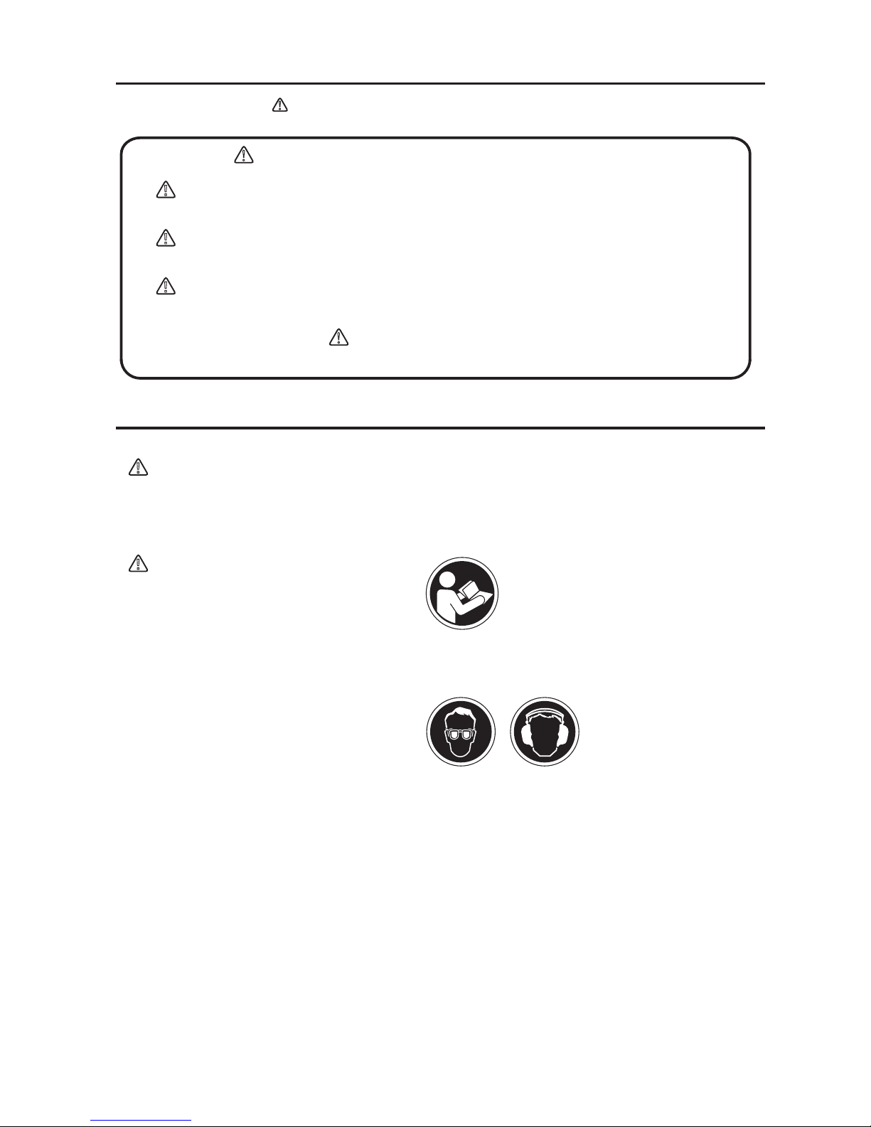
The triangle marks( ) used in this manual and on the decals on the machine
are warning symbols. Please follow these precautions.
Warning symbols indicating personnel hazards
DANGER:
!
WARNING:
!
CAUTION:
!
!
!
!
4-1. General Precautions
3. Warning Symbols
Extremely hazardous. If the warning is not followed, it is likely
to result in serious injury or death.
Hazardous. If the warning is not followed, it is likely to result in
serious injury or death.
Potential hazard. If the warning is not followed, it may result in
injury.
Precautions (without mark):
4. Safety Precautions
WARNING
!
DO NOT operate the machine,
- If you do not feel well due to overwork or illness.
- If you are taking any medicine.
- If you are under the influence of alcohol.
For details about the engine, refer the separate instruction manual for the engine.
Make sure you understand the structure of the machine well.
Always check the machine before your work to make sure it is in normal condition.ed.
Decals on the machine (operation method labels, warning labels, etc.) are very important for
your safety. Keep the machine clean so that the decals can be read all the time. Replace a
decal if it becomes illegible.
Before performing maintenance work, be sure to turn the engine off.
It is very dangerous if children come into close contact with the machine. Have the utmost
concern about how and where to store the machine. In particular, for an engine with a cell,
always remove the starter key and keep it in a designated place.
Before inspection and maintenance work, stop the engine, and do your work on a flat
surface area. If a cell is attached, remove the battery wiring before your work.
Mikasa does not accept any responsibility for accidents caused by remodeling or rework
done on the machine.
CAUTION
!
Read this manual carefully and
handle the machine as described to
ensure safe work.
For safe work, always wear protective
gear (helmets, safety shoes, ear
plugs, etc.) and work in appropriate
clothes.
■
■
■
■
■
■
■
■
■
■
■
3
If the warning is not followed, it may
result in property damage.
Page 8
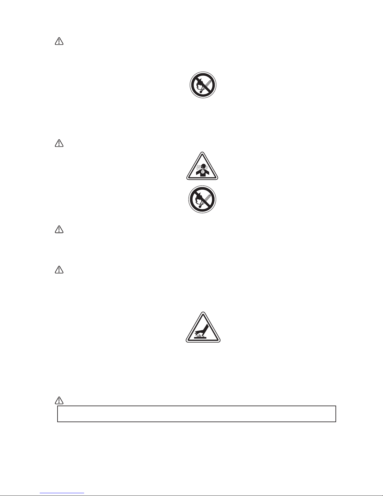
4-2. Refueling Precautions
DANGER
!
When adding fuel,
Do not fill to the rim due to potential spillage.
After adding the fuel, tightly close the tank cap
Check each part to see if it is tightened properly. Vibration causes loosening of bolts, which
results in unexpected serious malfunctions of the machine. Tighten the bolts securely.
Before starting the machine, make sure it is safe to start by checking your surroundings for
people and objects.
Always pay attention to your footing. Work in an area where you can maintain a good
balance of the machine and a safe comfortable posture.
If you notice deterioration of machine operation during your work, stop your work
immediately.
Before moving away from the machine, be sure to turn the engine off. Also when the
machine is transported, stop the engine and close the fuel cock.
For unloading using a crane, a licensed crane operator is needed. An operator should be
qualified for crane and hooking work.
Before lifting, check the machine parts (especially the hook and anti-vibration rubber) for any
damage and loosened or missing bolts.
Take the machine to a clear flat location without any combustibles nearby.
Be careful not to spill the fuel. Wipe
well if any spill occurs.
■
■
■
■
■
■
■
■
■
■
■
■
Make sure you work in a well ventilated location.
Make sure the engine is stopped and wait until it cools down.
-
-
-
4-3. Location and Ventilation Precautions
DANGER
!
4-6. Lifting Precautions
DANGER
!
DO NOT run the machine in an
unventilated location, such as indoors
or inside a tunnel. The exhaust gas
from the engine contains toxic gases
such as carbon monoxide and is very
hazardous.
DO NOT operate the machine near
open flames.
The engine and muffler become very
hot. Do not touch immediately after
the machine stops because they are
still very hot.
4-4. Precautions Before Starting
CAUTION
!
4-5. Precautions During Work
CAUTION
!
4
Page 9

WARNING
!
For safety reasons, do not lift to a height that is higher than necessary.
Stop the engine during transportation.
Transport after the engine and the machine are cooled down.
Always drain the fuel before transporting.
Securely fix the machine to prevent it from moving or falling during transportation.
Appropriate maintenance is required to ensure safe and efficient operation of the machine.
Always pay attention to the machine’ s condition and keep it in good condition. Pay special
attention to the parts used for lifting, if they are not maintained properly, it might result in a
serious accident.
Start maintenance work after the machine has cooled down completely. The muffler, in
particular, becomes very hot, and there is a danger of burn. The engine, engine oil and
vibrator also become very hot. Be careful not to get burned.
Always stop the engine before inspection and adjustment. If you are caught in a rotating
part, serious injury might occur.
After maintenance work, check the security parts to see if they are securely installed.
Special attention should be paid when checking bolts and nuts.
If disassembly is involved in maintenance, refer to the maintenance instruction manual to
make your work safe.
Never put the positive terminal and negative terminal come into contact. Sparks will be
generated, and ignition might occur.
Be careful when handling the battery fluid because it is very toxic. If the battery fluid gets on
your skin, eye, or clothes, rinse it off with plenty of water and consult with a doctor.
■
■
■
■
■
■
■
■
■
■
■
■
■
■
■
■
■
4-7. Transportation and Storage Precautions
WARNING
!
WARNING
!
4-8. Maintenance Precautions
Stop the engine and shut the fuel
cock while lifting.
Use a sufficiently strong wire rope.
For lifting, use only one point hoisting
hook, and do not lift at any other part.
When the machine is hoisted, never
let people or animals come underneath.
The gas from the battery might cause
an explosion. Do not generate sparks
or bring flames near the battery.
5
Lifting Precautions (Continued)
DANGER
!
CAUTION
!
Page 10
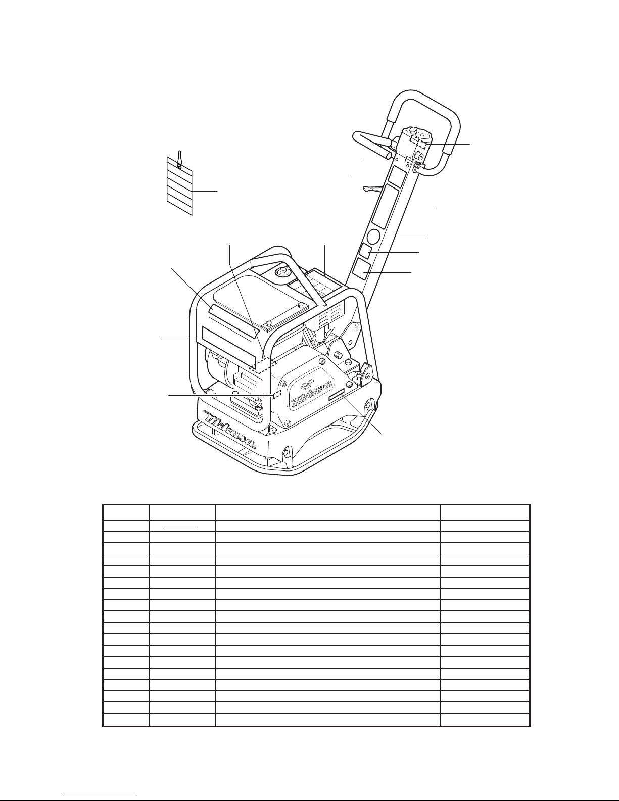
4-9. Labeling Positions
MVH-R60
-120
-150
7
2
1
5
5
8
10
6
11
9
12
3
4
13
6
Parts No. Parts Name Remarks
9201-10000
9202-07440
9202-07660
9202-09620
9202-07400
9202-07420
9202-07670
9202-07680
9202-07480
9202-00870
9202-01950
9202-10330
9202-10100
9202-07430
9202-03330
9202-07690
9202-09530
PLATE, SERIAL NO.
DECAL, MODEL/MVH-R60
DECAL, MODEL/MVH-120
DECAL, MODEL/MVH-150
DECAL, CAUTION/R60
DECAL, DANGER-CAUTION/MVH-150
DECAL, V-BELT RPF-3320
DECAL, V-BELT RPF-3350
DECAL, V-BELT RPF-3340
DECAL, SHELL TELLUS OIL 46
DECAL, WITHOUT ENGINE OIL
DECAL, OIL SAE 10W-30
DECAL, EC NOISE REQ.LWA105
DECAL, EC NOISE REQ.LWA108
DECAL, CAUTION/MVH-120
DECAL, EAR PROTECTION LABEL
DECAL, CAUTION/MANUAL
DECAL, CAUTION/COMBINATION
MVH-R60
MVH-120
MVH-150
MVH-R60
MVH-120/150
MVH-R60/120
MVH-150G
MVH-150D
MVH-R60
MVH-120/150
MVH-120/150
MVH-120/150
MVH-120/150
MVH-120/150
1
2
2
2
3
3
4
4
4
5
6
7
8
9
10
11
12
13
Label No.
Page 11

⑥
⑤
②
①
DANGER
OPERATIONAL CAUTION
FUEL
Fire risk
Operate only in well-
Wear ear protection
・ Prior to OPERATION, check engine oil and fuel levels.it not enough,add to proper levels.
・ Warm up engine at low speed for 3 to 5 minutes.
・ Operate machine at full throttle speed. (incorrect clutch engagement causes clutch to burn.)
・ Use travel lever for forward & reverse motion. Do not push or pull travel lever strongly.
Do not stand next to
Do not touch moving
ventillted area
Operate only in well-
ventillted area parts in operation
Read operator’s manual
carefully before use
machine while lifting
Do not use machine
handle
WARNING WARNING
NOISE
HOT TEMP. READ
CAUTION CAUTION
MOVING PARTS
DANGER
EXHAUST
DANGER
LIFTING
DANGER
LIFTING
③
⑧
④
⑦
4-10. Descriptions of Symbols Used on Warning Labels
Fire hazard
Stop the engine when refueling. Fire may occur if a flame is near the tank fuel port.
Danger: poisonous exhaust gas
Carbon monoxide poisoning may occur if the exhaust gas is inhaled. Do not operate the
machine in a poorly ventilated area.
Do not go under the lifted machine.
Do not let people or animals go under the lifted machine.
Lifting by the handle is prohibited.
Due to a falling risk, do not lift the machine by the handle.
Danger of hearing damage caused by noise
Always use ear plugs while operating the machine.
Be careful not to get burned.
Accidental burn may occur if you touch the hot parts (engine, muffler, etc.) during operation
or immediately after the machine stops.
Be careful not to be caught in rotating parts.
Make sure the engine is stopped when removing the belt cover during a belt change.
Read the manual carefully.
Always read the operation manual and have good understanding of operation before your
work.
(1)
(2)
(3)
(4)
(5)
(6)
(7)
(8)
WARNING
NOISE
Wear ear protection
①
②
③
⑤
⑦
⑧
Wear ear protection
WARNING
NOISE
①
②
③
⑤
⑦
⑧
Label No.3 Pars No.9202-09620 (MVH-R60)
Label No.3 Pars No.9202-07400 (MVH-120/150)
Label No.13 Pars No.9202-09530 ( MVH-150
D[L48]
)
※
Engine type except L48
Part No.9209-00110
DECAL, SET /MVH, MRH /EXP, EU
Do not use.
(For rollers)
NPA-1473
Do not use.
(For rollers)
NPA-1475
NPA-1474
NPA-1476
(MVH-150D is
excluded.)
Decal for new European machine directives
7
Page 12

Caution Decals on Engine
Fire hazard
Stop the engine when refueling. Fire may occur if a flame is near the tank fuel port.
Danger: poisonous exhaust gas
Carbon monoxide poisoning may occur if the exhaust gas is inhaled. Do not operate the
machine in a poorly ventilated area.
Do not go under the lifted machine.
Do not let people or animals go under the lifted machine.
Lifting by the handle is prohibited.
Due to a falling risk, do not lift the machine by the handle.
Danger of hearing damage caused by noise
Always use ear plugs while operating the machine.
Be careful not to get burned.
Accidental burn may occur if you touch the hot parts (engine, muffler, etc.) during operation
or immediately after the machine stops.
Be careful not to be caught in rotating parts.
Make sure the engine is stopped when removing the belt cover during a belt change.
Read the manual carefully.
Always read the operation manual and have good understanding of operation before your
work.
(1)
(2)
(3)
(4)
(5)
(6)
(7)
(8)
Fire hazard
Stop the engine when refueling. Fire may occur if a flame is near the tank fuel port.
Danger: poisonous exhaust gas
Carbon monoxide poisoning may occur if the exhaust gas is inhaled. Do not operate the
machine in a poorly ventilated area.
Hot muffler
Do not touch the muffler and its surrounding area.
Read operation manual
For safe operation, always read the operation manual before use.
Fire, open flame and smoking prohibited.
(1)
(2)
(3)
(4)
(5)
8
Robin Honda
WARNING
!
STOP
WARNING
!
⑤
②
②
①
①
③
④
④
(1)
(2) (3)
(4)
(5)
(6)
(7) (8)
(MVH-150D is excluded. Refer to engine instruction manual for MVH-150D.)
Page 13

5. Specifications
Model
Dimensions(mm)
Overall Length
Overall Width
Overall Height
Plate Size
(W x L)
V-Belt Size
Lubrication Oil
in vibration case
(cc)
Weight
Operating
Weight
(kg)
Performance
Max, Travelling
Speed
Vibrating
Frequency
Centrifugal
Force
Power Source
Manufacturer
Model
Max.Output
Fuel Tank
Capacity
Set R.P.M
68
Honda
GX120
(petrol)
2.6kW(3.5PS)
/3600min
-1
2.0L
69
Robin
EX13
(petrol)
3.2kW(4.3PS)
/4000min
-1
2.7L
MVH-R60
886
350
880
350 x 480
RPF-3320
200
0-25m/min
100Hz
(6000v.p.m)
15kN
(1530kgf)
3600min
-1
(3600rpm)
105
104
7.6
105
104
7.5
108
107
5.5 [2.5]
108
106
5.2
108
107
8.8
108
107
5.8
111
110
8.7
108
106
9.2
MVH-120GR
1030
400
900
400 x 585
RPF-3320
350
118
0-23m/min
100Hz
(6000v.p.m)
22.5kN
(2300kgf)
Robin
EH17-2D
(petrol)
3.7kW(5.0PS)
/4000min
-1
3.6L
3600min
-1
(3600rpm)
MVH-150GH
1130
430
920
430 x 700
RPF-3350
350
150
0-25m/min
90Hz
(5400v.p.m)
27kN
(2750kgf)
Honda
GX200
(petrol)
4.1kW(5.6PS)
/3600min
-1
3.1L
3600min
-1
(3600rpm)
MVH-150GR
1130
430
920
430 x 700
RPF-3350
350
161
0-25m/min
90Hz
(5400v.p.m)
27kN
(2750kgf)
Robin
EH25-2D
(petrol)
5.9kW(8.0PS)
/3600min
-1
6.0L
3600min
-1
(3600rpm)
1130
430
920
430 x 700
RPF-3340
350
150
0-25m/min
90Hz
(5400v.p.m)
27kN
(2750kgf)
Robin
DY23-2D
(diesel)
3.7kW(5.0PS)
/3600min
-1
3.2L
3200min
-1
(3200rpm)
1130
430
920
430 x 700
RPF-3340
350
158
0-25m/min
90Hz
(5400v.p.m)
27kN
(2750kgf)
Yanmar
L48N6-VSMK
(diesel)
3.5kW(4.7PS)
/3600min
-1
2.5L
3200min
-1
(3200rpm)
MVH-150D
MVH-150D
(Silent Type)
9
Guaranteed sound
power level(dB)
(in comply with
2000/14/EC)
Measured sound
power level(dB)
(in comply with
2000/14/EC)
Hand Arm Vibration
(m/sec2)
(in comply with
2002/44/EC)
1030 [1120]
400
900 [990]
400 x 585
RPF-3320
350
116 [118]
0-23m/min
100Hz
(6000v.p.m)
22.5kN
(2300kgf)
Honda
GX160
(petrol)
3.6kW(4.9PS)
/3600min
-1
3.1L
3600min
-1
(3600rpm)
MVH-120GH
[VAS]
Page 14

6-1. Outside Dimension
(mm)
6. Appearance
400 (MVH-120)
430 (MVH-150)
900 (MVH-120)
990 (MVH-120 VAS)
920 (MVH-150)
585 (MVH-120)
700 (MVH-150)
1030 (MVH-120)
1120 (MVH-120 VAS)
1130 (MVH-150)
MVH-R60
350
880
480
886
MVH-R60
MVH-120
MVH-150
10
Page 15

ENGINE
GUARD FRAME
HANDLE
(WORKING
POSITION)
HANDLE
(STORING
POSITION)
LIFTING FOOK
THROTTLE LEVER
TRAVEL LEVER
BREATHER CAP
HAND PUMP
( )
Hydraulic oil :
Shell Terrace Oil #46 or equivalent
FORWARD
REVERSE
NEUTRAL
BELT COVER
STARTING KNOB
VIBRATION CASE
HANDLE GRIP
HANDLE LOCK
OIL GAUGE FOR VIBRATION CASE
( )
Lubrication oil :SAE 10W-30
6-2. Parts and Component
THROTTLE LEVER
11
Page 16

7. Inspection Before Operation
Clean each part of the machine well to maintain
dirt and dust-free condition. Pay special attention
to the soil attached to the bottom of the compacting board, engine cooling air inlet, and the carbu-
retor and air cleaner area to keep those parts clean.
Check each part for any looseness of bolts. Vibration causes bolts to loosen, which might result in
unexpected accident or malfunction.
Inspect the guard hook, belt cover and antivibration rubber to check the function of speed
adjustment wire and speed adjusting lever.
Check for oil leakage from the hydraulic pump and
hoses.
Check the V-belt tension. (See p.19.) The belt
should have about 10–15mm of flexibility when
pushed strongly with a finger at the mid-point
between the axes. If the V-belt is loosened, power
is not transmitted well, which reduces compacting
force and shortens the life of the V-belt.
Set the engine on a level surface to check the oil
level. If the oil level is low, add oil. Use the following engine oil.(Fig. 1)
Set the machine on a level surface, then remove
the oil gauge of the vibrator. Check the oil gauge
to see if the oil is at the specified level. Use engine
oil SAE10W-30 as lubrication oil.
Recommended oil quantity for MVH-R60 is 200cc
and MVH-120/150, 350cc. (Fig. 2)
Refueling
-Do not expose to open flames while refueling.
-Do
not fill to the rim because the fuel might spill.
-Wipe off well if a spill occurs.
Use clean automotive gasoline or automotive light
oil appropriate for the engine. Let the fuel run
hrough a filter when refueling.
Quality:
Grade CC or above
Grade SE or above
Viscosity:
SAE No. 30 at 20°C and above(summer)
SAE10W-30
Diesel engine oil,
Gasoline engine oil,
1.
2.
3.
4.
5.
6.
7.
8.
Upper Level
Lower Level
(refil needed)
Oil Gauge
fig.1
Effective
Measure oil volume
Not necessary to screw
fig.2
DANGER
!
12
OPERATIONAL CAUTION
Check engine oil and fuel level.
If not enough, add to proper level.
To START engine:
1.Warm up engine at low speed for 3 to 5 minutes.
2.Operate machine always at full speed to avoid
incorrect clutch engagement.
3.Use travel lever for forward and reverse motion.
Do not push or pull lever strongly.
To STOP engine:
Move stop switch to "OFF' position.
To LIFT machine by using lifting hook in center
To STORE machine covered with plastic sheet in a moisture.
Do not move travel lever
if engine stops (MVH-120/150)
Prior to OPERATION:
Page 17

Gasoline Engine
Set the fuel cock lever to the “Out” position to
let the fuel flow. (Fig. 3-1, 3-2, 3-3)
In cold weather or when the engine does not
start easily, set the choke lever to the “Start”
position. This is not necessary when the engine
is already warmed up. (Fig. 4-1, 4-2, 4-3)
1.
2.
8. Operation
8-1. Starting
Choke (HONDA)
fig.4-1
Start
Choke Lever
Choke (ROBIN EX-TYPE)
fig.4-2
Start
Choke Lever
Fuel Cock
(HONDA)
fig.3-1
Fuel Cock Lever
FLOW
Fuel Cock
(ROBIN EX-TYPE)
fig.3-2
Fuel Cock Lever
“
l
”
“
O
”
13
Fuel Cock
(ROBIN EH-TYPE)
fig.3-3
Fuel Cock Lever
“ l ”
“
O
”
Choke (ROBIN EH-TYPE)
fig.4-3
Start
Choke Lever
Page 18

Slightly move the throttle lever at the handle to
high. (Fig. 5)
Turn the engine switch to “ON (operation)”.
(Fig.6)
Hold the recoil starter grip, and pull it a little.
You will feel a slight resistance. Then, pull it
hard to run the engine. Be careful not to pull
too hard, or the rope might break or come off.
Allow the starter rope to slowly move back into
the case while keeping the grip grabbed.
(Fig. 7-1, 7-2)
After the engine has started, while you hear
some explosion loud noise, gradually move
back the choke lever until it is wide open.
(Fig. 8-1, 8-2)
-When the choke lever is set to “Start”,
gradually move it back toward the “Operation” direction while making sure the enginerevolution stabilizes.
3.
4.
5.
6.
Choke (HONDA)
fig.8-1
Operation
(Open)
Choke Lever
Starter Grip (HONDA)
fig.7-1
Starter Grip
Starter Grip (ROBIN)
fig.7-2
Starter Grip
14
fig.5
Throttle Lever
fig.6
“ON”
ON
“ON”
HONDA ROBIN
Engine Switch
Page 19

After the engine has started, warm up the
engine at low speed for 2 to 3 minutes. This is
especially important in cold weather. While
warming up, check for any abnormalities
suchas gas leakage.
-After the engine has started, return the
speed adjustment lever to the low speed
position. If it is left “half open”, the centrifugal clutch remains slipping. It might cause
the centrifugal clutch to fail, and abnormal
vibration of the machine might result and
create very dangerous situation.
7.
15
Choke (ROBIN EX-TYPE)
fig.8-2
Choke Lever
Operation(Open)
Choke (ROBIN EH-TYPE)
fig.8-3
Choke Lever
Operation(Open)
Page 20

Diesel Engine (MVH-150D)
Open the fuel cock lever. (Fig 9)
Open the throttle lever to about 30° for the
idling position. (Fig.10)
Recoil starter
Do not pull the rope completely. Allow the
start knob to slowly move back while keeping the knob grabbed. If you let the knob off
your hand, the rope will suddenly move
back, resulting in damage of the knob,
engine, or the main body.
After the engine has started, warm up the
engine at low speed for 2 to 3 minutes. This is
especially important in cold weather. While
warming up, check for any abnormalities such
as gas leakage.
1.
2.
3.
4.
fig.10
Throttle Lever
Open by about
30 degress
fig.9
Fuel Cock
Close
Open
CAUTION
!
If you pull the starting knob slowly, you will
feel some resistance at a point (the compression point). After you feel the resistance,
slowly return the starting knob.
Push down the decompressor lever.
Pull the starting knob hard to start the engine.
(Fig. 11)
a.
b.
c.
fig.11
Recoil Starter
16
Page 21

While the machine is in operation, make
sure there is no object or structure that
might cause injury or machine damage in
the direction that the machine is moving.
If the throttle lever is opened suddenly, the
machine starts to operate. At an engine revolution of around 2000 rpm, the clutch engages,
but if the engine revolution is increased gradually, slipping of the clutch occurs (halfclutching), which results in wear and malfunction of the clutch. So, the operation of the
speed adjustment level should be done quickly
and suddenly without a hesitation.
Use the back and forth travel lever to make the
machine move backward and forward. When
the lever is pushed forward, the machine
moves forward, when pulled backward, the
machine moves backward. At neutral, the
machine vibrates staying at the same location.
(Fig. 12)
When this machine is used on ground that
contains clay, the ground surface tends to stick
to the compacting board, and the machine
travel speed becomes slower. In this case,
check the bottom of the compacting board to
see if there is any clay adhered to the board.
This machine cannot perform well on clay and
other type of ground with a high water percentage. Drying the ground is recommended to
make the ground water percentage appropriate
for the machine to get good compacting performance.
-
1.
2.
3.
fig.12
Travel Lever
Reverse
Neutral
Forward
CAUTION
!
8-2. Operation
17
Page 22

Move the throttle lever from ON to OFF (for
diesel engine, to idle position). Run the engine
for 3 to 5 minutes at low speeds to cool it down
before stopping.
Diesel Engine
Move the throttle lever to the stop position to
stop the engine.
Gasoline Engine
Turn the engine switch to the OFF position,
then the engine stops. (Fig. 13)
If the engine is stopped while it is hot, burning of the oil film on the cylinder inner wall
occurs, leading to troubles such as accelerated engine wear.
For gasoline engine, shut the fuel cock.
(Fig. 14-1, 14-2)
1.
-
-
2.
fig.13
Engine Switch
“OFF”
HONDA ROBIN
ON
“OFF”
9. Stopping the Machine
Fuel Cock
(HONDA)
fig.14-1
OFF
Fuel Cock Lever
Fuel Cock
(ROBIN EX-TYPE)
fig.14-2
“ O ”
“
l
”
Fuel Cock Lever
CAUTION
!
18
Fuel Cock
(ROBIN EH-TYPE)
fig.14-3
Fuel Cock Lever
“ l ”
“
O
”
Page 23

10-1. Loading and Unloading
10-2. Transportation Precautions
10. Transportation
11. Storage
WARNING
!
WARNING
!
Make sure there is no breakage of guard frame and anti-vibration rubber nor
loosened or missing bolts.
Always stop the engine when lifting.
Use an intact wire rope without any deformation with sufficient strength.
Slowly lift upward without applying any impact. Never let people or animals go under
the lifted machine.
For safety reasons, do not lift to a height that is higher than necessary.
Stop the engine when the machine is transported.
Always drain the fuel before transportation.
Fix the machine securely to prevent the machine from moving or falling.
For loading and unloading using a
crane, an operator qualified for
cranes and hooking works is
needed.
Use a crane for loading and unloading the machine.
Designate a person to guide the loading and unloading, and always work
under the instruction of that person.
When lifting, always use a special
hook on the guard frame. (Fig. 15)
Never lift by using the hook on the
handle.
Wash with water to remove any dust
and dirt from all parts of the machine.
Store in a dry area away from direct
sunlight after putting the cover over
the machine to prevent dust and dirt
buildup.
Add fuel and oil or perform an oil
change. Remove the battery terminals or remove the battery from the
machine for storage.
Securely cover the air cleaner and
muffler air inlets and exhaust port.
Do not leave the machine outdoors.
Keep it indoors.
(When storing for a long period of time)
■
■
■
■
■
1.
2.
3.
■
■
■
1.
2.
3.
4.
5.
fig.15
Special Hook
19
Page 24

Check frequency
Check parts Check items Oils
Appearance
Fuel tank
Fuel system
Engine oil
Shock absorber
Hand pump
Vibrator oil
Hydraulic pipe system
Air cleaner
Guard frame
Back and forth motion
lever, linking parts
Back and forth motion
lever operation
Bolts and nuts
Engine oil
Engine oil filter
Engine oil
Engine oil filter
Vibrator oil
Hydraulic oil
Battery terminal
V-belt for vibrator
Clutch
Vibrator oil
Hydraulic oil
Fuel filter
Engine oil filter
Fuel pipes
Air cleaner element
Hydraulic hose
Daily
(before starting)
Every 20 hours
Every 100 hours
Every 200 hours
Every 300 hours
Every 2 years
Irregular
Flaw, deformation
Leakage
Leakage
Leakage, oil level, dirt
Crack, damage, wear
Leakage
Leakage
Leakage, looseness, flaw, wear
Dust on sponge
Breakage, flaw, loosened or
missing bolts and nuts
Missing, breakage, flaw, looseness or
missing bolts and nuts
Operation check, play
Looseness, missing
Replace only after the first 20 hours
Replace only after the first 20 hours
Change
Washing
Leakage, oil level, dirt
Leakage, oil level, dirt
Cleaning
Flaw, tension
Dirt, flaw, wear
Change
Change
Change
Change
Change
Change
Change
gasoline
Engine oil
Hydraulic oil
Engine oil
Hydraulic oil
Engine oil
Engine oil
Engine oil
Hydraulic oil
Engine oil
Hydraulic oil
6mm 8mm 10mm 12mm 14mm 16mm 18mm 20mm
4T (SS41) 70 150 300 500 750 1,100 1,400 2,000
6-8T (S45C)
100 250 500 800 1,300 2,000 2,700 3,800
11T (SCM3)
150 400 800 1,200 2,000 2,900 4,200 5,600
When the mating material is aluminum
100 300~350 650~700
Thread diameter
Material
(Bolts used on the machine are right-hand thread.)
12-1. Inspection and Maintenance Schedule Table
12. Regular Check and Adjustment
For details about the check and maintenance of the engine, please refer to the
attached engine operation manual.
Caution: The above table shows the check frequency for standard condition. The
check frequency may vary depending on the condition in which the machine is used.
For check of bolt and nut looseness and tightening, please see the following tightening torque list.
Tightening Torque List (unit: kgf-cm, 1kgf-cm=9.80665N-cm)
20
Page 25

Perform the first engine oil change after 20
hours of operation, then change at every 100
hours.
When the air cleaner element becomes dirty,
the engine does not start smoothly, and sufficient output cannot be obtained. Machine
operation will be affected and the engine life
will be shortened greatly. Do not forget to clean
the element. (For details, please see the separate engine operation manual.) If the element
cannot be cleaned, replace it with a new one.
Check of V-belt (Fig. 16)
At every 200 hours, remove the belt cover (top)
to check the tension of the V-belt. The flexibility
of the belt should be about 10 mm when
pushed strongly with your finger at the midpoint between the axes. When the V-belt is
loose, the engine power is not transmitted well,
resulting in poor compacting force and shortening the life of the V-belt.
Changing the V-belt
Removing the V-belt
Remove the top and bottom belt covers. Put a
wrench (19mm) on the tightening bolt of the
vibrator pulley (lower side). Put a piece of cloth
at the center of the left side of the V-belt, and
pull the belt strongly towards you. While pulling,
turn the wrench clockwise, then remove the
V-belt.
Installing the V-belt
Set the V-belt on the lower side of the vibrator
pulley. Push the V-belt to the left side of the
upper clutch. Similar to removing the V-belt,
turn the wrench clockwise to install.
Be careful not to get your hand caught
between the belt and clutch pulley. Injury
may occur. Wear gloves when performing
this operation. (Fig. 17)
Checking the Clutch
Check the clutch when checking the V-belt.
Remove the belt cover and check for any seizing on the clutch outside drum. Also visually
check for wear and damage on V-groove. If the
V-groove is dirty, clean it thoroughly.
Wear on the lining shoe can be checked by an
operation check. Wear on the shoe will result in
poor power transmission, causing slipping.
To stop the operation, perform the starting
steps in reverse. Return the throttle lever
quickly and suddenly to lower the revolution
speed.
1.
2.
-
-
3.
-
fig.16
Belt Cover(upper)
Clutch
Belt
Belt Cover (lower)
Vibration Pulley
fig.17
CAUTION
!
12-2. Changing the Engine Oil
12-3. Cleaning the Air Cleaner
12-4. Checking/Changing the V-belt and Clutch
21
Page 26

Changing the Clutch
Remove the V-belt. (See the belt removing
steps described in the previous page.)
Remove the bolt at the engine output shaft end
by applying an impact (hitting with a hammer)
to the spanner. (in a counterclockwise direction).
Remove the clutch with a pulley remover.
For installation, perform the previous steps in
reverse. When tightening the bolt, apply a
shock to the spanner to tighten securely.
If vibration becomes weaker during operation or when there is no vibration even
though the engine is running normally,
immediately check the V-belt and clutch with
disregard to the rule of every 200 hours
check.
At every 100 hours of operation, set the
machine on a level surface and remove the oil
gauge of the vibrator. Check the oil level to see
if it is within the allowable range. (Fig.18)
Change the vibrator oil at every 300 hours
operation. Drain the oil from the drain plug. For
draining, put a beam under the compacting
board at the other side of the drain plug to tilt
the machine.
Use engine oil SAE 10W-3D as lubrication
oil. The quantity used is 200cc for MVH-R60
and 350cc for MVH-120/150.
When checking the vibrator oil, clean the oil
port beforehand to prevent dust and other
foreign materials from falling into the oil.
Whenever there is an oil leakage from the
vibrator, check the oil level.
Check the Hydraulic Oil
Check the hydraulic oil at every 100 hours’
operation. By making the handle bar vertical
(done at the time of storage), remove the
breather plug at the top of the hydraulic hand
pump to see if the hydraulic oil is at the specified level (OIL LEVEL). (Fig. 19)
4.
-
-
-
-
※
1.
fig.18
Effective
For MVH-R60/120/150
Measure oil volume
Not necessary to screw
fig.19
Cap
Breather Plug
Hand Pump
OIL LEVEL
CAUTION
!
CAUTION
!
12-5. Checking/Changing the Vibrator Oil
(Fig.18)
12-6. Checking/Changing the Hydraulic Oil
22
Page 27

Changing the Hydraulic Oil (Fig. 20)
The level of the hydraulic oil in the hand
pump should always be at OIL LEVEL. If the
level is higher, the oil bursts out from the
breather plug.
Be careful not to let dust enter inside the
hand pump.
Remove the hand pump plug cap, then remove
the breather plug (with a 24 mm wrench).
Remove the hydraulic hose that is in the vibrator cylinder. Set the lever to the forward motion
to drain the hydraulic oil in the pump.
After the hydraulic oil is drained, install the
hydraulic hose to the vibrator.
Pour hydraulic oil from the hand pump breather
plug attachment hole.
(MVH-R60: 0.25L, MVH-120/150: 0.3L)
Remove the air releasing plug of vibrator cylinder. Then oil will come out from the air releasing plug. After air bubbles stop coming out,
attach the plug. Tighten securely.
Attach the hand pump breather plug, put on the
plug cap. After making sure the hydraulic oil in
the pump is at OIL LEVEL, attach the breather
plug.
Hydraulic oil: Shell Terrace Oil #46 or
equivalent
2.
-
-
a.
b.
c.
d.
e.
■
fig.20
Hydraulic Hose Breather Plug
Vibrator
CAUTION
!
23
Page 28

Revolution fluctuation
(1) Starting Problem
(2) Operation Problems
(3) Recoil Starter Operation not Good
13-1. Gasoline Engine
13. Troubleshooting
Bridging the igniter plug.
Carbon accumulated on the igniter plug.
Short circuit due to insulation problems of the igniter plug.
Inappropriate spark gap.
Short circuit of the ON-OFF switch
Ignition coil problems
Dirt of the point or inappropriate gap.
Breakage of ignition coil or short circuit
Intake/exhaust valve is stuck or pushed up
Piston ring, cylinder wear
Cylinder head, igniter plug tightening problem
Head gasket, igniter plug gasket breakage
Water mixed in fuel
Dirt of the igniter plug.
Ignition coil problem
Occasional short circuit of the ignition coil
No fuel in the fuel tank.
Fuel cock does not open properly.
Clogging of fuel filter.
Clogging of tank cap air hole
Air trapped in the fuel pipe.
The wrong fuel is used.
Mixing of water or foreign materials
The air cleaner not working
Dirt of air cleaner.
Carbon accumulated in the cylinder.
Carburetor oil level inappropriate.
Carbon accumulated inside combustion chamber and exhaust hole.
Spark plug thermal value inappropriate.
Dirt and breakage of the cooling fin.
Clogging of foreign materials at the rotating part.
Weakening of the spiral spring
Governor adjustment inappropriate
Governor spring problems
Fuel does not flow properly.
Air taken from intake pipe system
Fuel is supplied, but the igniter plug does not ignite.
■
■
■
■
■
■
Fuel supplied, and the igniter plug ignites.
Fuel does not reach the carburetor.
Lowered power.
Engine overheating
Compression is good and no firing problem.
Compression is good, but no firing.
Insufficient compression (see the item “compression is not good.” )
Compression is good
Compression is not good
Electricity reaches the high voltage cable.
Electricity does not reach the high voltage cable.
24
Page 29

Intake/exhaust valve upthrust
Decompressor adjustment problems
(1) Starting Problem
(2) Insufficient Output and Operation Problems
Contact with seat not close enough.
Piston ring wear
Cylinder wear
Cylinder, cylinder head mating surface problems
Nozzle seat looseness
No compression at all
Almost no compression
Clogging of the tank cap air hole.
Clogging of the fuel filter
Fuel cock not open
Air inside the fuel pipe
Fuel flow low or no flow
Injection pump barrel, plunger stuck
Nozzle hole clogging
Nozzle needle stuck
Fuel not injected inside the combustion chamber
Inappropriate starting operations
Engine oil viscosity high, engine oil is very dirty.
Air trapped inside the fuel pipe.
Does not reach the starting revolution.
Governor fork and sleeve mating surface problems
Governor spring problems
Fly plate and sliding part wear and operation problems
Revolution fluctuation
Valve open/close timing inappropriate
Clogged exhaust hole, muffler
Overload
Engine revolution does not increase.
Dirt and breakage of cooling fin
Mixing of water inside the fuel filter
Carbon accumulated in the combustion chamber or exhaust hole.
Smoke set inappropriate
Overload
Inappropriate injecting timing
Nozzle clogging
Engine overheating with black smoke
See the comment for insufficient compression.
Insufficient compression
No fuel in the fuel tank
Mixing of water or foreign materials
(A) In case of compression problems
(B) In case of inappropriate fuel injection inside the combustion chamber
(C) Fuel and compression pressure appropriate, but the engine does not start.
13-2. Diesel Engine
25
■
■
■
■
■
■
■
■
■
■
■
Page 30

Piston, cylinder ring wear
Nozzle hole clogging
Piston ring stuck
Wrong assembly (upside down) of piston ring
Inappropriate injection timing
Inappropriate valve open/close timing
Looseness of injection pump joint
Firing problem with white smoke (when unloaded)
Hand pump problems
Inappropriately installed forward/backward motion lever
Breakage of the oil hose
Mixing of air in the hydraulic oil
Clogging of foreign materials in the check valve inside the hand pump
Breakage of the piston bearing in cylinder
Move forward or backwards, but unable to switch between back and forth motion
Insufficient engine output and inappropriate high speed set revolution
Slipping of clutch
Slipping of V-belt
Too much vibrator oil
Failure inside vibrator
Low travel speed and vibration weak
Leakage from fuel passage
Clogging of the air cleaner element
Inappropriate fuel due to mixing of impurities
Overload
Fuel consumption too high (black smoke)
V-belt coming off, slipping and breakage
Slipping of the clutch
Locking of the vibrator
Breakage of the piston bearing in cylinder
No forward, backward motion
Piston inside the hand pump not moving smoothly
Vibrator cylinder piston does not move smoothly
Movement of lever heavy
Use of wrong oil
Failure to change oil
Breakage of the air cleaner element or failure to clean the air cleaner
Extensive wear on sliding parts or stuck piston rings
Too much oil
Wrong assembly of the governor system
Detached injection pump rack
Engine does not stop even though the fuel supply is cut (or over-running)
Searing or damage of the piston, rod, etc.
Stopped suddenly with abnormal noise
Wear on the injection pump barrel or plunger
Lubrication oil diluted and increased.
13-3. Main Body
■
■
■
■
■
■
■
■
■
■
26
Page 31

Page 32

 Loading...