


OPERATION AND PARTS MANUAL
 SERIES
MODEL MTX-70
TAMPING RAMMER
(HONDA GX100UKRBF GASOLINE ENGINE)
Revision #5 (01/04/08)
To find the latest revision of this publication, visit our website at: www.multiquip.com
THIS MANUAL MUST ACCOMPANYTHE EQUIPMENT AT ALLTIMES.

MTX-70 — PROPOSITION 65WARNING
PAGE 2 — MTX-70 — OPERATION AND PARTS MANUAL — REV. #5 (01/04/08)

NOTES
MTX-70 — OPERATION AND PARTS MANUAL — REV. #5 (01/04/08) — PAGE 3
MTX-70 Tamping Rammer
Proposition 65 Warning ........................................... |
2 |
Table Of Contents ................................................... |
4 |
Parts Ordering Procedures ..................................... |
5 |
Safety Message Alert Symbols ............................ |
6-7 |
Rules For Safe Operation .................................... |
8-9 |
General Information .............................................. |
10 |
Specifications ........................................................ |
11 |
Controls and Components .................................... |
12 |
Basic Engine ......................................................... |
13 |
Operation ......................................................... |
14-16 |
Maintenance ......................................................... |
17 |
Troubleshooting Guide ..................................... |
18-19 |
Explanation Of Codes In Remarks Column .......... |
20 |
Suggested Spare Parts ......................................... |
21 |
Name Plate and Decals ................................... |
22-23 |
Crankcase and Engine Assembly .................... |
24-27 |
Guide Cylinder and Foot Assembly ................. |
28-29 |
Foot Assembly ................................................. |
30-31 |
Tank and Handle Assembly ............................. |
32-33 |
Combination Lever Assembly .......................... |
34-35 |
Tools ................................................................. |
36-37 |
MTX-70 —TABLE OF CONTENTS
HONDA GX100UKRBF ENGINE
Cylinder Barrel Assembly ................................... |
38-39 |
Crankcase Cover Assembly............................... |
40-41 |
Crankshaft Assembly ......................................... |
42-43 |
Piston Connecting Rod ...................................... |
44-45 |
Camshaft Assembly ........................................... |
46-47 |
Recoil Starter Assembly..................................... |
48-49 |
Fan Cover Assembly .......................................... |
50-51 |
Carburetor Assembly ......................................... |
52-53 |
Air Cleaner Assembly......................................... |
54-55 |
Muffler Assembly ............................................... |
56-57 |
Flywheel Ignition Assembly................................ |
58-59 |
Control Assembly ............................................... |
60-61 |
Labels Assembly ................................................ |
62-63 |
Terms and Condition Of Sale — Parts .................... |
64 |
Specification and part number are subject to change without notice.
PAGE 4 — MTX-70 — OPERATION AND PARTS MANUAL — REV. #5 (01/04/08)
www.multiquip.com

PARTS ORDERING PROCEDURES
Ordering parts has never been easier!
Choose from three easy options:
Best Deal! Order via Internet (Dealers Only):
Orderpartson-lineusingMultiquip’sSmartEquipwebsite!
■View Parts Diagrams
■Order Parts
■Print Specification Information
Goto www.multiquip.com and click on
Order Parts to log in and save!
Effective:
January 1st, 2006
If you have an MQ Account, to obtain a Username and Password, E-mail us at: parts@multiquip.com.
To obtain an MQ Account, contact your District Sales Manager for more information.
Use the internet and qualify for a 5% Discount on Standard orders for all orders which include complete part numbers.*
Note: Discounts Are Subject To Change
|
|
|
|
|
|
|
|
|
Order via Fax (Dealers Only): |
|
|
|
|
|
|
|
|
|
|
|
|
|
|
|
|
|
|
|
|
|
|
|
|
|
|
|
|
|
|
|
|
|
|
|
|
|
|
|
|
|
|||||||||||||||||||||||||||||
|
|
|
|
|
|
|
|
|
|
|
|
|
|
|
Fax your order in and qualify for a 2% Discount |
|
|||||||||||||||||||||||||||||||||||||||||||||||||||||||||||||||
|
|
|
|
|
|
|
|
|
|
|
|
|
|
|
|
||||||||||||||||||||||||||||||||||||||||||||||||||||||||||||||||
|
|
|
|
|
|
|
|
||||||||||||||||||||||||||||||||||||||||||||||||||||||||||||||||||||||||
|
|
|
|
|
|
|
|
|
All customers are welcome to order parts via Fax. |
|
|
|
|
|
|
on Standard orders for all orders which include |
|
||||||||||||||||||||||||||||||||||||||||||||||||||||||||||||||
|
|
|
|
|
|
|
|
||||||||||||||||||||||||||||||||||||||||||||||||||||||||||||||||||||||||
|
|
|
|
|
|
|
|
|
|
|
|
|
|
|
|
||||||||||||||||||||||||||||||||||||||||||||||||||||||||||||||||
|
|
|
|
|
|
|
|
|
Domestic (US) Customers dial: |
|
|
|
|
|
|
complete part numbers.* |
|
||||||||||||||||||||||||||||||||||||||||||||||||||||||||||||||
|
|
|
|
|
|
|
|
||||||||||||||||||||||||||||||||||||||||||||||||||||||||||||||||||||||||
|
|
|
|
|
|
|
|
|
1-800-6-PARTS-7 (800-672-7877) |
|
|
|
|
|
|
|
|
|
|
|
|
|
|
|
|
|
|
|
|
|
|
|
|
|
|
|
|
|
|
|
|
|
|
|
|
|
|
|
|
|
|||||||||||||||||||||||||||||
|
|
|
|
|
|
|
|
|
|
|
|
|
|
|
|
|
|
|
|
|
|
|
|
|
|
|
|
Note: Discounts Are Subject To Change |
|||||||||||||||||||||||||||||||||||||||||||||||||||
|
|
|
|
|
|
|
|
|
|
|
|
|
|
|
|
|
|
|
|
|
|
|
|
|
|
|
|
|
|
|
|||||||||||||||||||||||||||||||||||||||||||||||||
|
|
|
|
|
|
|
|
|
|
|
|
|
|
|
|
|
|
|
|
|
|
|
|
|
|
|
|
|
|
|
|
|
|
|
|
|
|
|
|
|
|
|
|
|
|
|
|
|
|
|
|
|
|
|
|
|
|
|
|
|
|||||||||||||||||||
|
|
|
|
|
|
|
|
|
|
|
|
|
|
|
|
|
|
|
|
|
|
|
|
|
|
|
|
|
|
|
|
|
|
|
|
|
|
|
|
|
|
|
|
|
|
|
|
|
|
|
|
|
|
|
|
|
|
|
|
|
|
|
|
|
|
|
|
|
|
|
|
|
|
||||||
|
|
|
|
|
|
|
|
|
|
|
|
|
|
|
|
|
|
|
|
|
|
Order via Phone: Domestic (US) Dealers Call: |
|
|
|
|
|
|
|
|
|
|
|
|
|
|
|
|
|
|
|
|
|||||||||||||||||||||||||||||||||||||
|
|
|
|
|
|
|
|
|
|
|
|
|
|
|
|
|
|
|
|
|
|
|
|
|
|
|
|
|
|
|
|
|
|
|
|
|
|
|
|
|
|
||||||||||||||||||||||||||||||||||||||
|
|
|
|
|
|
|
|
|
|
|
|
|
|
|
|
|
|
|
|
|
|
|
|
|
|
|
|
|
|
|
|
|
|
|
|
|
|
|
|
|
|
||||||||||||||||||||||||||||||||||||||
|
|
|
|
|
|
1-800-427-1244 |
|
|
|
|
|
|
|
|
|
|
|
|
|
|
|
|
|
|
|
|
|
|
|
|
|
|
|
|
|
|
|
|
|||||||||||||||||||||||||||||||||||||||||
|
|
|
|
|
|
|
|
|
|
|
|
|
|
|
|
|
|
|
|
|
|
|
|
|
|
|
|
|
|
|
|
|
|
|
|
|
|
|
|
|
|
|
|
|
|
|
|
|
|
|
|
|
|
|
|
|
|
|
|
|
|
|
|
|
|
|
|
|
|
|
|
|
|
|
|
|
|
|
|
|
|
|
|
|
|
|
|
|
|
|
|
|
|
|
|
|
|
|
|
|
|
|
|
|
|
|
|
|
|
|
|
|
|
|
|
|
|
|
|
|
|
|
|
|
|
|
|
|
|
|
|
|
|
|
|
|
|
|
|
|
|
|
|
|
|
|
|
|
|
|
|
|
|
|
|
|
|
|
|
|
|
|
|
Non-Dealer Customers: |
|
|
|
|
|
|
|
|
|
|
International Customers should contact |
|
|
|
|
|
|||||||||||||||||||||||||||||||||||||||||||||||||||||||||||
|
|
|
|
|
|
|
|
|
|
|
|
|
|
|
|||||||||||||||||||||||||||||||||||||||||||||||||||||||||||||||||
|
|
|
|
|
|
|
|
|
|
|
|
|
|
|
|||||||||||||||||||||||||||||||||||||||||||||||||||||||||||||||||
|
|
|
|
Contact your local Multiquip Dealer for |
|
|
|
|
|
|
|
|
|
|
|
|
|
|
|
|
|
||||||||||||||||||||||||||||||||||||||||||||||||||||||||||
|
|
|
|
|
|
|
|
|
|
|
|
|
|
|
|
|
|
|
|
|
|
|
|
|
|||||||||||||||||||||||||||||||||||||||||||||||||||||||
|
|
|
|
|
|
|
|
|
|
|
|
|
|
their local Multiquip Representatives for |
|
|
|
|
|
||||||||||||||||||||||||||||||||||||||||||||||||||||||||||||
|
|
|
|
parts or call 800-427-1244 for help in |
|
|
|
|
|
|
|
|
|
|
|
|
|
|
|
|
|
||||||||||||||||||||||||||||||||||||||||||||||||||||||||||
|
|
|
|
|
|
|
|
|
|
|
|
|
|
Parts Ordering information. |
|
|
|
|
|
||||||||||||||||||||||||||||||||||||||||||||||||||||||||||||
|
|
|
|
locating a dealer near you. |
|
|
|
|
|
|
|
|
|
|
|
|
|
|
|
|
|
|
|
|
|
||||||||||||||||||||||||||||||||||||||||||||||||||||||
|
|
|
|
|
|
|
|
|
|
|
|
|
|
|
|
|
|
|
|
|
|
|
|
|
|
|
|
|
|
|
|
|
|
|
|
|
|
|
|
|
|
|
|
|
|
|
|
|
|||||||||||||||||||||||||||||||
|
|
|
|
|
|
|
|
|
|
|
|
|
|
|
|
|
|
|
|
|
|
|
|
|
|
|
|
|
|
|
|
|
|
|
|
|
|
|
|
|
|
|
|
|
|
|
|
|
|
|
|
|
|
|
|
|
|
|
|
|
|
|
|
|
|
||||||||||||||
|
|
|
|
|
|
|
|
|
|
|
|
|
When ordering parts, please supply: |
||||||||||||||||||||||||||||||||||||||||||||||||||||||||||||||||||
|
|
|
|
Dealer Account Number |
Specify Preferred Method of Shipment: |
||||||||||||||||||||||||||||||||||||||||||||||||||||||||||||||||||||||||||
|
|
|
Dealer Name and Address |
|
|
UPS/Fed Ex |
DHL |
||||||||||||||||||||||||||||||||||||||||||||||||||||||||||||||||||||||||
|
|
|
Shipping Address (if different than billing address) |
|
|
|
|
|
|
|
■ Priority One |
Truck |
|||||||||||||||||||||||||||||||||||||||||||||||||||||||||||||||||||
|
|
|
|
|
|
|
|
|
|
■ Ground |
|
|
|
|
|
|
|
|
|
|
|
|
|
|
|
|
|
|
|
|
|||||||||||||||||||||||||||||||||||||||||||||||||
|
|
|
|
Return Fax Number |
|
|
|
|
|
|
|
|
|
|
|
|
|
|
|
|
|
|
|
|
|
|
|
|
|
|
|
||||||||||||||||||||||||||||||||||||||||||||||||
|
|
|
|
|
|
|
|
|
|
■ Next Day |
|
|
|
|
|
|
|
|
|
|
|
|
|
|
|
|
|
|
|
|
|||||||||||||||||||||||||||||||||||||||||||||||||
|
|
|
|
Applicable Model Number |
|
|
|
|
|
|
|
|
|
|
|
|
|
|
|
|
|
|
|
|
|
|
|
|
|
|
|
||||||||||||||||||||||||||||||||||||||||||||||||
|
|
|
|
|
|
|
|
|
|
■ Second/ThirdDay |
|
|
|
|
|
|
|
|
|
|
|
|
|
|
|
|
|
|
|
|
|||||||||||||||||||||||||||||||||||||||||||||||||
Quantity, Part Number and Description of Each Part
All orders are treated as Standard Orders andwillshipthesamedayifreceivedprior to 3PM PST.
WE ACCEPT ALL MAJOR CREDIT CARDS!
MTX-70 — OPERATION AND PARTS MANUAL — REV. #5 (01/04/08) — PAGE 5
MTX-70 — SAFETY MESSAGE ALERT SYMBOLS
FORYOUR SAFETY ANDTHE SAFETY OF OTHERS! |
|
HAZARD SYMBOLS |
|
|
|
Safety precautions should be followed at all times when operating this equipment. Failure to read and understand the Safety Messages and Operating Instructions could result in injury to yourself and others.
This Owner's Manual has been developed to provide complete instructions for the safe and efficient operation of the MQ Mikasa, Model MTX-70Tamping Rammer. Refer to the engine manufacturer's instructions for data relative to its safe operation.
Before using this rammer, ensure that the operating individual has read and understands all instructions in this manual.
SAFETY MESSAGE ALERT SYMBOLS
The three (3) Safety Messages shown below will inform you about potential hazards that could injure you or others. The Safety Messages specifically address the level of exposure to the operator, and are preceded by one of three words: DANGER,
 DANGER
You WILL be KILLED or SERIOUSLY INJURED if you DO NOT follow these directions.
 WARNING
You CAN be KILLED or SERIOUSLY INJURED if you DO NOT follow these directions.
 CAUTION
You CAN be INJURED if you DO NOT follow these directions.
Potential hazards associated with the operation of an MTX-70 Tamping Rammer will be referenced with Hazard Symbols which appear throughout this manual, and will be referenced in conjunction with Safety Message Alert Symbols.
 WARNING Lethal Exhaust Gas Hazards
Engine exhaust gases contain poisonous carbon monoxide. This gas is colorless and odorless, and can cause death if inhaled. NEVER operate this equipment in a confined area or enclosed structure that does not provide ample free flow air.
 WARNING Explosive Fuel Hazards
Gasoline is extremely flammable, and its vapors can cause an explosion if ignited. DO NOT start the engine near spilled fuel or combustible fluids.
DO NOT fill the fuel tank while the engine is running or hot. DO NOT overfill tank, since spilled fuel could ignite if it comes into contact with hot engine parts or sparks from the ignition system. Store fuel in approved containers, in well-ventilated areas and away from sparks and flames.
|
WARNING |
Burn Hazards |
Engine components can generate extreme heat. To prevent burns, DO NOT touch these areas while the engine is running or immediately after operations. Never operate the engine with heat shields or heat guards removed.
|
WARNING |
Respiratory Hazards |
ALWAYS wear approved respiratory protection when required.
PAGE 6 — MTX-70 — OPERATION AND PARTS MANUAL — REV. #5 (01/04/08)

MTX-70 — SAFETY MESSAGE ALERT SYMBOLS
|
CAUTION |
Rotating Parts Hazards |
|
|
|
NEVER operate equipment with covers, or guards removed. Keep fingers, hands, hair and clothing away from all moving parts to prevent injury.
 CAUTION Accidental Starting Hazards
ALWAYS place the ON/OFF switch in the OFF position when the rammer is not in use.
|
CAUTION |
Eye and Hearing Hazards |
|
|
|
ALWAYS wear approved eye and hearing protection.
|
DANGER |
Refueling Hazard |
|
|
|
NEVER refuel rammer when placed in truck bed with plastic liner.The possibility exists of explosion due to static electricity. When adding fuel, remove rammer from truck bed and place on ground.
|
CAUTION |
Equipment Damage |
|
Hazards |
|
|
|
Other important messages are provided throughout this manual to help prevent damage to your light tower, other property, or the surrounding environment.
|
CAUTION |
Lifting Handle |
|
|
|
Before starting operation, check the lifting handle to make sure there is no damage on the bolts, no cracks or breakage on the handle, and no fissure on the surface.
This handle is for manual lifting only. Use handle to lift the shoe part of the rammer with the body laid down on the ground or truck bed. Use proper lifting techniques to avoid back injury.
Do not use this rammer as a rammer lift point. Use the lifting point on top of the rammer.
Do not move the rammer with the lifting handle and the front rollers more than 5 meters.
 CAUTION- Read Manual Read Manual
Before attempting to operate the pump, and to avoid serious injury to personnel, always read and understand operation manual. Failure to read and understand operation manual could result in serious harm or even death!
MTX-70 — OPERATION AND PARTS MANUAL — REV. #5 (01/04/08) — PAGE 7
MTX-70 — RULES FOR SAFE OPERATION
|
DANGER |
Read this manual! |
|
|
|
Failure to follow instructions in this manual may lead to serious injury or even death! This equipment is to be operated by trained and qualified personnel only! This equipment is for industrial use only.
The following safety guidelines should always be used when operating the MTX-70 Tamping Rammer:
GENERAL SAFETY
■DO NOT operate or service this equipment before reading this entire manual.
■This equipment should not be operated by persons under 18 years of age.
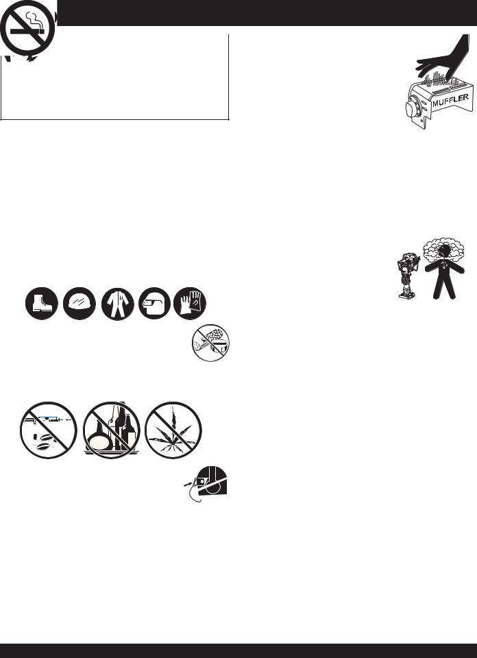
■NEVER operate this equipment without proper protective clothing, shatterproof glasses, steel-toed boots and other protective devices required by the job.
■NEVER operate this equipment when not feeling well due to fatigue, illness or taking medicine.
■NEVER operate this equipment under the influence of drugs or alcohol.
■ALWAYS wear proper respiratory (mask), 
 hearing and eye protection equipment when
 operating the rammer.
■Whenever necessary, replace nameplate, operation and safety decals when they become difficult read.
■Manufacturer does not assume responsibility for any accident due to equipment modifications.
■NEVER use accessories or attachments, which are not recommended by Multiquip for this equipment. Damage to the equipment and/or injury to user may result.
■NEVER touch the hot exhaust manifold, muffler or cylinder. Allow these parts to cool before servicing
engine or rammer.
■High Temperatures – Allow the engine to cool before adding fuel or performing service and maintenance functions. Contact with hot! components can cause serious burns.
■The engine section of this rammer requires an adequate free flow of cooling air. NEVER operate the rammer in any enclosed or narrow
area where free flow of the
air is restricted. If the air flow is restricted it will cause serious damage to the rammer or engine and may cause injury to people.
Remember the rammer's engine gives off DEADLY carbon monoxide gas.
■ALWAYS refuel in a well-ventilated area, away from sparks and open flames.
■ALWAYS use extreme caution when working with flammable liquids. When refueling, stop the engine and allow it to cool.DO NOT smoke around
or near the machine. Fire or explosion could result from fuel vapors, or if fuel is spilled on a hot engine.
■NEVER operate the rammer in an explosive atmosphere or near
combustible materials. An explosion or fire could result causing severe bodily harm or even death.
■DO NOT smoke around or near the machine. Fire or explosion could result from fuel vapors, or if fuel is spilled on a hot engine.
■Topping-off to filler port is dangerous, as it tends to spill fuel.
■Stop the engine when leaving the rammer unattended.
■Maintain this equipment in a safe operating condition at all times.
PAGE 8 — MTX-70 — OPERATION AND PARTS MANUAL — REV. #5 (01/04/08)

MTX-70 — RULES FOR SAFE OPERATION
■ALWAYS stop the engine before servicing, adding fuel and oil.
■NEVER run engine without air filter. Severe engine may occur.
■ALWAYS service air cleaner frequently to prevent carburetor malfunction.
■ALWAYS check the machine for loosened threads or bolts before starting.
■ALWAYS be sure the operator is familiar with proper safety precautions and operations techniques before using rammer.
■ALWAYS store equipment properly when it is not being used. Equipment should be stored in a clean, dry location out of the reach of children.
■DO NOT operate this equipment unless all guards and safety devices are attached and in place.
■CAUTION must be exercised while servicing this equipment.
Rotating and moving parts can cause injury if contacted.
■Keep all inexperienced and unauthorized people away from the equipment at all times.
■Unauthorized equipment modifications will void all warranties.
■NEVER pour or spray water over the engine.
■Test the engine ON/OFF switch before operating. The purpose of this switch is to shut down the engine of the rammer.
■Refer to the HONDA Engine Owner's Manual for engine technical questions or information recommended by Multiquip for this equipment.
TRANSPORTING
■ALWAYS shutdown engine before transporting.
■Tighten fuel tank cap securely and close fuel cock to prevent fuel from spilling.
■Drain fuel when transporting rammer over long distances or bad roads.
■When placing the rammer inside a truck-bed for transport, always tie-down the rammer
MAINTENANCE
■NEVER lubricate components or attempt service on a running rammer.
■ALWAYS allow the rammer a proper amount of time to cool before servicing.
■Keep the rammer in proper running condition.
■Fix damage to the rammer immediately and always replace broken parts.
■Dispose of hazardous waste properly. Examples of potentially hazardous waste are used motor oil, fuel and fuel filters.
■DO NOT use food or plastic containers to dispose of hazardous waste.
EMERGENCIES
■ALWAYS know the location of the nearest fire extinguisher and first aid kit.
■In emergencies always know the location of the nearest phone or keep a phone on the job site. Also know the phone numbers of the nearest ambulance, doctor and fire department. This information will be invaluable in the case of an emergency.
MTX-70 — OPERATION AND PARTS MANUAL — REV. #5 (01/04/08) — PAGE 9

Definition of Tamping Rammer
The Mikasa MTX-70 tamping rammer is a powerful compacting tool capable of applying a tremendous force in consecutive impacts to a soil surface. Its applications include soil compacting for road, embankments and reservoirs as well as backfilling for gas pipelines, water pipelines and cable installation work.
The impact force of the MTX-70 levels and uniformly compacts voids between soil particles to increase dry density.
Circular motion is converted to create impact force.The MTX70 tamping rammer develops a powerful compacting force at the foot of the rammer. To maintain optimum performance, proper operation and service are essential.
Construction of Tamping Rammer
The Mikasa MTX-70 is equipped with an air cooled, fourcycle gasoline engine.Transmission of the power takes place by increasing the engine speed to engage the centrifugal clutch.
Rammer Gearbox and Spring Cylinder
The Mikasa MTX-70 uses an oil bath lubrication system. Always check the oil level through the oil level sight glass at the rear of the tamper foot.
Controls
Before starting the MTX-70 Tamping Rammer identify and understand the function of the controls.
MTX-70 — GENERAL INFORMATION
|
CAUTION |
Handle Operation |
|
|
|
Before starting operation check the lifting handle to:
1.Make sure that there is no damage on the bolts.
2.Make sure that there is no crack or breakage on handle.
3.Make sure that there is no fissure on the surface. If there is any abnormality or damage, replace with new one.
For operation:
This handle is to be used to lift up the shoe part of the machine with the body laid down on the ground or truck bed.
1.Use proper lifting techniques to avoid back injury.This handle is for manual lifting only.
2.Do not use this handle as a rammer lift point. Use the lifting point on the top of the machine.
3.Do not move the rammer with the lifting handle and the front rollers more than 16 feet (5 meters).
PAGE 10 — MTX-70 — OPERATION AND PARTS MANUAL — REV. #5 (01/04/08)
|
|
|
|
MTX-70 — SPECIFICATIONS |
|
|
|
|
|
|
|
|
Table 1. MTX-70 Rammer Specifications |
|
|||
|
|
|
|
|
|
|
Overall Height |
|
|
39.37 in. (1000 mm) |
|
|
|
|
|
|
|
|
Overall Width |
|
|
13.78 in (350 mm) |
|
|
|
|
|
|
|
|
Over Length |
|
|
31.02 in (788 mm) |
|
|
|
|
|
|
|
|
Shoe Size |
|
|
13.4 x 11.2 (340 x 285 mm) |
|
|
|
|
|
|
|
|
Fuel Tank Capacity |
|
|
3.2 qt. (3 liters) |
|
|
|
|
|
|
|
|
Lubrication Oil Capacity |
|
|
0.8 quart (0.75 liter) |
|
|
|
|
|
|
|
|
No. of Impacts Per Second |
|
10.7 - 11.5 |
|
|
|
|
|
|
|
|
|
Impact Force |
|
|
2,855 lb (12.7 kN) |
|
|
|
|
|
|
|
|
Impact Plate Stroke |
|
|
2 -3.15 in (50 - 80 mm) |
|
|
|
|
|
|
|
|
Operating Weight |
|
|
165.34 lbs. (75 kg) |
|
|
|
|
|
|
|
|
|
|
|
|
|
|
Table 2. |
Engine Specifications |
|
||
|
|
|
|
|
|
|
Model |
|
Honda GX100UKRBF Engine |
|
|
|
|
|
|
|
|
|
Type |
|
Air-Cooled 4 Stroke, Overhead camshaft, |
|
|
|
|
single cylinder gasoline engine |
|
||
|
|
|
|
|
|
|
|
|
|
|
|
|
Piston Displacement |
|
6.0 cu.in. (98 cc) |
|
|
|
|
|
|
|
|
|
Max. Output |
|
3.0 hp/3,600 rpm (2.2 KW) |
|
|
|
|
|
|
|
|
|
Max. Governed Speed, No Load |
|
3,800 - 4,100 rpm |
|
|
|
|
|
|
|
|
|
Cooling System |
|
Air-Cooled |
|
|
|
|
|
|
|
|
|
Engine Oil Capacity |
|
0.3 qt. (0.28 liters) |
|
|
|
|
|
|
|
|
|
Fuel |
|
Unleaded gasoline |
|
|
|
|
|
|
|
|
|
Lubricant for Engine |
|
Automobile Oil; Class SE or higher |
|
|
|
|
|
|
|
|
|
Starting System |
|
Recoil Starter |
|
|
|
|
|
|
|
|
|
Spark Plug Type |
|
NGK CR5HSB |
|
|
|
|
|
|
|
|
Specifications are general and are subject to change without notice. If exact measurements are required, equipment should be weighed and measured.
MTX-70 — OPERATION AND PARTS MANUAL — REV. #5 (01/04/08) — PAGE 11
MTX-70 — CONTROLS AND COMPONENTS
3
2
4
10
1
5
9
6 
11
7 12
8 |
13 |
|
|
|
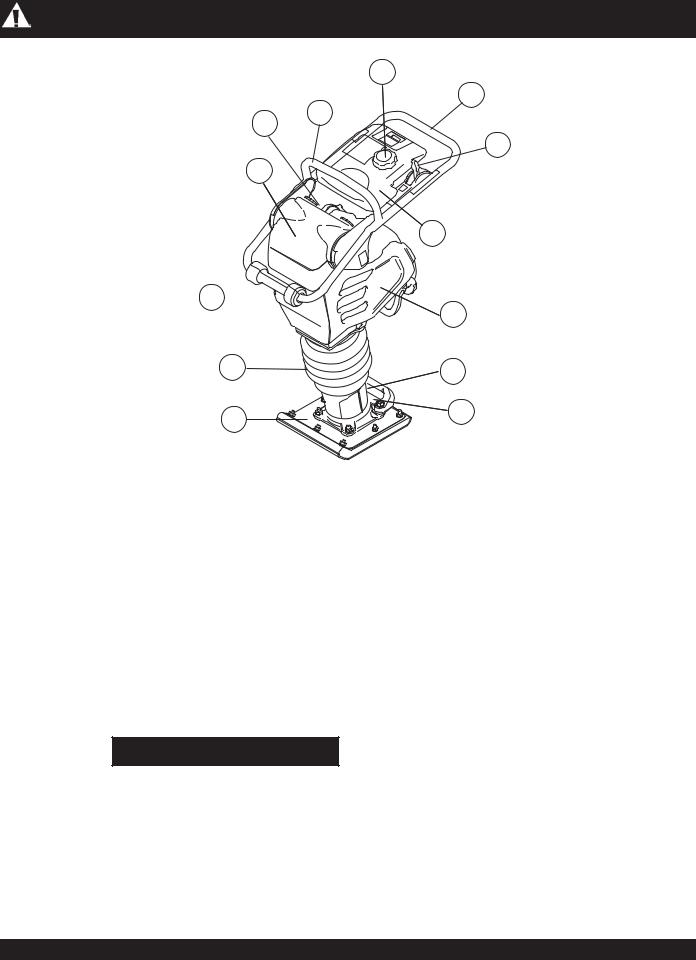
Figure 1. MTX-70 Rammer |
Figure 1 shows the location of the controls and components for the MTX-70 Tamping Rammer. The functions of each control is described below:
1. Combination (Throttle) Lever – Used to adjust engine speed (rpm).Move lever forward (SLOW)to reduce engine speed,moveleverbacktowardoperator(FAST)toincrease speed. Always operate the rammer at full speed (rpm).
2.Handle – To operate rammer, GRIP handle assembly firmly on both sides.
3.Fuel Tank Cap – Remove this cap to add unleaded gasolinetothefueltank.Makesurecapistightenedsecurely. DO NOT over fill.
WARNING
Addingfueltothetankshouldbeaccomplishedonly when the engine is stopped and has had an opportunitytocooldown. Intheeventofafuelspill, DO NOT attempt to start the engine until the fuel residue has been completely wiped up, and the area surrounding the engine is dry.
4. Hook – Used to lift rammer for transporting.
5. Air Cleaner Cover – Protects the air cleaner which prevents dirt and other debris from entering the engine.
6.Roller – Allows rammer to be moved around easily by rolling the unit.
7.Bellows – Reservoir for oil bath.
8.Foot – Laminated wood with tempered steel plate for superior shock absorption.
9.FuelTank – Holds the fuel for the unit (up to 3.2 quarts)
10.Muffler – reduces the noise of the engine when running.
11.Engine– thisunitusesaHondaGX100UKRBFgasoline engine.
12.Oil Gauge (Sight Glass) – Indicates the level of oil in the oil bath reservoir.
13.Drain Valve – Open this valve to remove oil from the bellows.
PAGE 12 — MTX-70 — OPERATION AND PARTS MANUAL — REV. #5 (01/04/08)
MTX-70 — BASIC ENGINE
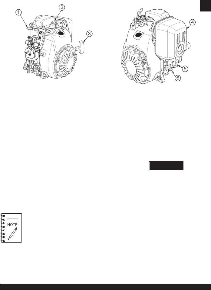
Figure 1A. Engine Controls and Components
(Honda GX100)
INITIAL SERVICING
The engine (Figure 1A) must be checked for proper lubrication and filledwithfuelpriortooperation. RefertothemanufacturersEngine manual for instructions & details of operation and servicing.
1. Choke Lever –Used when starting the engine. Normally used in cold weather conditions. In cold weather turn the choke lever to the fully closed position, in warm weather set choke lever half way or completely open.
2. Spark Plug – Provides spark to the ignition system. Set spark plug gap to 0.024 - 0.028 inch (0.6 - 0.7 mm). Clean spark plug once a week.
3. Recoil Starter (pull rope) – Manual-starting method. Pull the starter grip until resistance is felt, then pull briskly and smoothly.
Operating the engine without an air filter, with a damaged air filter, or a filter in need of replacement will allow dirt to enter the engine, causing rapid engine wear.
4. Muffler – Used to reduce noise and emissions.
WARNING
Enginecomponentscangenerateextremeheat. To prevent burns, DO NOT touch these areas while the engine is running or immediately after operating. NEVER
operate the engine with the muffler removed.
5. |
Dipstick/Oil Filler Cap – Remove this cap to determine if |
|
the engine oil is low. Add oil through this filler port as |
|
recommended in Table 3. |
6. |
Oil Drain Plug – Remove this plug to remove oil from the |
|
engine's crankcase. |
MTX-70 — OPERATION AND PARTS MANUAL — REV. #5 (01/04/08) — PAGE 13
This section is intended to assist the operator with the initial start-up of the MTX-70 Tamping Rammer. It extremely important that this section be read carefully before attempting to operate the rammer.
DO NOT use your rammer until this section is thoroughly understood.
MTX-70 — OPERATION
Engine
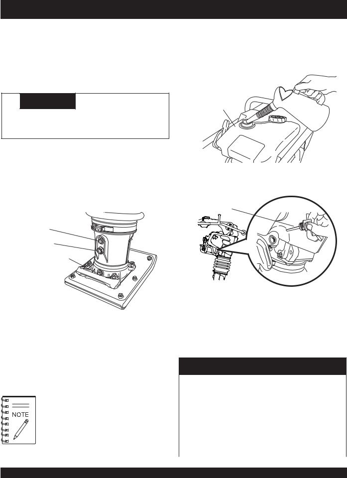
1.Fill the fuel tank (Figure 3) with unleaded gasoline. At the same time, check the engine oil and make it a habit to replenish it often (Figure 4).
 CAUTION
Failure to understand the operation of the MTX-70Tamping Rammer could result in severe damage to the unit or personal injury.
FUEL TANK
Rammer Crankcase and Spring Cylinder Oil Bath |
|
This unit uses an oil bath lubrication system.Perform the following: |
|
1. Checktheoillevelthroughtheoillevelsightglass(Figure2) |
Figure 3. Fuel Tank |
at the rear of the tamper foot. |
|
OIL LEVEL
DIPSTICK
OIL FILL PLUG
SIGHT GLASS
OIL DRAIN PLUG
Figure 4. Engine Oil Dipstick
Figure 2. Foot Housing Sight Glass
2.Ifoilisnotvisible,add10W-30SE,SForhighergrademotor oil into the oil fill plug opening (Figure 2).The bath contains approximately 1.7 pints (800 cc.)
Theoillevelshouldbekeptatthehalfwaypointof the sight glass.
2.Low levels of oil may result in engine seizure due to high levels of consumption during operations.
3.Check the engine oil level and if the engine oil level is low, it should be refilled. Use the proper motor oil as suggested in the Table 3 below.
Table 3 Motor Oil Grade
Season or Temperature |
Grade of motor oil |
||
(higher than MS class) |
|||
|
|
||
|
|
||
Spring, Summer or Autumn |
SAE 30 |
||
+120° F to +15° F |
|||
|
|||
|
|
|
|
Winter |
|
SAE 30 |
|
+40° F to +15° |
F |
||
|
|||
|
|
|
|
Below +15° F |
|
SAE 10W-30 |
|
|
|
|
|
PAGE 14 — MTX-70 — OPERATION AND PARTS MANUAL — REV. #5 (01/04/08)
Inspection
1. Check all nuts, bolts fasteners for tightness. Retighten as necessary.
2.Clean anydirtfromtherecoil starterand footpedestal. Wipe the entire unit clean before operating.
3.ReplaceanymissingordamagedSafetyOperationdecals.
4.Adjustheightofhandle.Adjusthandlebylooseningnutsand moving handle to suit operation. Retighten nuts.
Initial Start-up
When starting the MTX-70 Tamping Rammer perform the following:
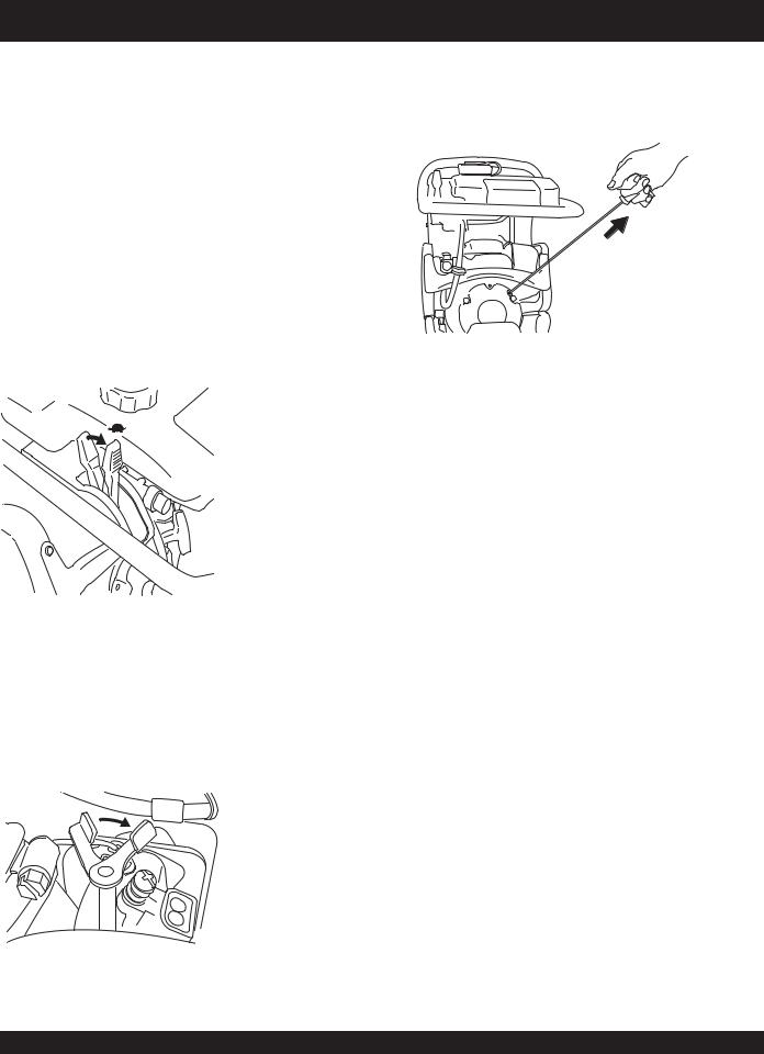
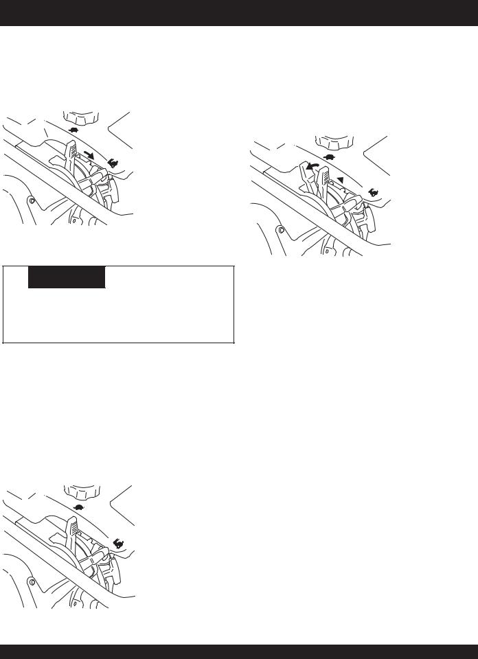
1.Slidethethrottleleverfromthestoptotheidleposition( ) (Figure 5).Thisopensthefuelcockandtheengineelectrical circuit is turned on automatically.
 THROTTLE LEVER (IDLE POSITION)
Figure 5. Throttle Lever (Idle {Position)
2.Place the choke lever to the closed position. When the weather is cold, close the choke all the way.When it is hot, or if the engine is hot, open the choke a little or leave it fully open.
 CHOKE LEVER (CLOSED POSITION)
MTX-70 — OPERATION
3.Gripthestarterropehandle (Figure7handleandpullituntil you feel a slight resistance.Then pull sharply and quickly. Return the handle to the starter case before releasing.
 STARTER
ROPE
Figure 7. Recoil Starter
4.Ifenginefailstostart,movethechokelever(Figure 6) tothe half open position to avoid flooding.
5.Repeat steps 1 thru 4.
6.If the engine does not start after repeated attempts, check the spark plug for excess fuel. Clean and replace the spark plug as needed.
Figure 6. Choke Lever
MTX-70 — OPERATION AND PARTS MANUAL — REV. #5 (01/04/08) — PAGE 15
Operation
1.To start the rammer tamping action, move the throttle lever
(Figure 8) quickly from IDLE to the START ( ) position. DO NOT move the throttle lever slowly as this may cause damage to the clutch or spring.
 THROTTLE LEVER (START POSITION)
Figure 8. Throttle Lever (Start Position)
 CAUTION
Make sure that the throttle lever is moved to the FULL START position. Operating the rammer at less than full speeds can result in damage to the clutch springs or foot.
2.The MTX-70 tamping rammer is designed to run at 3,800 to 4,100 rpm. Atoptimumrpmthefoothitsat theratebetween 590~695impacts per minute. Increasing throttlespeedpast factorysetrpmdoesnotincreaseimpacts and maydamage unit.TheMTX-70isdesignedtoadvancewhiletamping.For faster advance, pull back slightly on the handle so that rear offootcontactssoilfirst.
3.To stop the tamping action, move throttle lever quickly from START to IDLE position (Figure 9).
 THROTTLE LEVER (IDLE POSITION)
MTX-70 — OPERATION
Stopping The Engine
Normal Shutdown
1.MovethrottleleverquicklyfromtheSTARTtoIDLEposition (Figure9)andruntheengineforthreeminutesatlowspeed. After the engine cools, move the throttle lever to the STOP position (Figure 10).The engine will stop and the fuel cock is automatically closed.
 THROTTLE LEVER (STOP POSITION)
Figure 10. Throttle Lever (Stop Position)
2.If the engine does not stop due to a problem with the switch orthelike, movethemachinetoasafelocationandholdthe throttlelever inthestopposition.Letthemachinerunonidle and the machine will stop after a few minutes.
Figure 9. Throttle Lever (Idle Position)
PAGE 16 — MTX-70 — OPERATION AND PARTS MANUAL — REV. #5 (01/04/08)
Maintenance
Perform the scheduled maintenance procedures as indicated:
DAILY
■Thoroughly remove dirt and oil from the engine and control area.
■Clean or replace the air cleaner elements as necessary. Check and retighten all fasteners as necessary.
■Check the spring box and bellows for oil leaks. Repair or replace as needed.
EVERY50HOURS
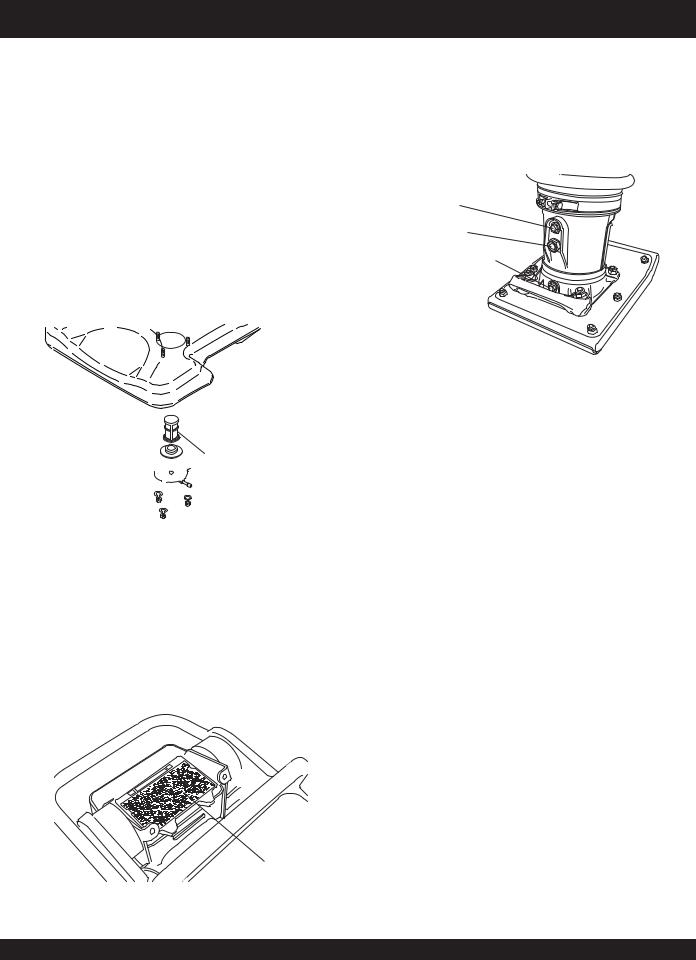
■Remove the fuel filter cap and clean the inside of the fuel tank (Figure 11).
MTX-70 — MAINTENANCE
EVERY200HOURS
■Remove the oil drain plug on foot housing (Figure 13) and drain the oil. Refill with approximately 1.7 pt. (800 cc.) of 10W-30 SE, SF or higher grade motor oil. Oil should be midway in sight glass. Break in oil should be changed after first 50 hours.
OIL FILL PLUG
SIGHT GLASS
OIL DRAIN PLUG
Figure 13. Oil Drain Plug
 FUEL FILTER
Figure 11. Fuel Filter
■Remove and clean the spark plug, then adjust the spark gap to 0.024~0.028 inch (0.6~0.7 mm).
EVERY 80 to 100 HOURS
■Remove the air cleaner cover. Loosen and remove the 2 screws that hold the cover to the air cleaner assembly.If the primary element (Figure 12) is dirty, wash it with gasoline or kerosene.Then dip it in engine oil (SAE10W-30) and wring the element so that 25 to 30 cc of engine oil remains on the element.
PRIMARY
ELEMENT
Figure 12. Air Cleaner Primary Element
EVERY2YEARS
■ Replace the fuel line every 2 years even if there is no visible damage.
Long Term Storage
■Slide the throttle lever to the STOP position.
■Drain any fuel including in the fuel hose.
■Replace lubrication oil and apply grease to lubrication points.
■Cover the air intake on the air cleaner and the exhaust outlet on the muffler.
■Store unit indoors covered with plastic sheet in moisture free and dust free location out of direct sunlight.
MTX-70 — OPERATION AND PARTS MANUAL — REV. #5 (01/04/08) — PAGE 17

|
MTX-70 —TROUBLESHOOTING GUIDE |
||
|
|
|
|
|
TABLE 4. ENGINE TROUBLESHOOTING |
||
|
|
|
|
SYMPTOM |
POSSIBLE PROBLEM |
SOLUTION |
|
|
|
|
|
Difficult to start |
|
|
|
|
|
|
|
|
Ignition plug being bridge? |
Check ignition system. |
|
|
|
|
|
Fuel is available but spark plug |
Carbon deposit at ignition? |
Clean or replace ignition. |
|
|
|
||
will not ignite. (Power available |
Short circuit due to defective |
Replace insulators. |
|
at high tension cable). |
|||
insulators? |
|
||
|
|
||
|
|
|
|
|
Improper spark gap? |
Set spark plug gap to the correct gap. |
|
|
|
|
|
Fuel is available but spark plug |
Short circuit at stop switch? |
Check stop switch circuit. Replace stop switch if defective. |
|
will not ignite. (Power NOT |
|
|
|
|
|
||
available at high tension cable). |
Ignition coil defective? |
Replace ignition coil. |
|
|
|
|
|
|
Muffler clogged with carbon |
Clean or replace muffler. |
|
|
deposits? |
|
|
Fuel is available and spark plug |
|
|
|
Fuel in use inadequate (water, |
Flush fuel sytem and replace with fresh fuel. |
||
ignites (compression normal). |
|||
dust)? |
|
||
|
|
||
|
|
|
|
|
Air Cleaner clogged? |
Clean or replace air cleaner. |
|
|
|
|
|
Fuel is available and spark plug |
Cylinder worn? |
Replace cylinder. |
|
|
|
||
ignites (compression low). |
Spark plug loose? |
Tighten spark plug. |
|
|
|||
|
|
|
|
Low compression. |
Incorrect valve adjustment? |
Check and adjust valves. |
|
|
|
|
|
Operation not satisfactory |
|
|
|
|
|
|
|
|
Air cleaner clogged? |
Clean or replace air cleaner. |
|
Not enough power available |
|
|
|
|
|
||
(compression normal, no miss- |
Air in fuel line? |
Bleed (remove air) from fuel line. |
|
firing). |
|
|
|
Carbon deposits in cylinder? |
Clean or replace cylinder |
||
|
|||
|
|
|
|
|
Ignition coil defective? |
Flush fuel sytem and replace with fresh fuel. |
|
Not enough power available |
|
|
|
Ignition plug often shorts? |
Replace ignition wires, clean ignition. |
||
(compression normal, miss- |
|||
|
|
||
firing). |
Fuel in use inadequate (water, |
Flush fuel sytem and replace with fresh fuel. |
|
|
|||
|
dust)? |
|
|
|
|
|
|
|
Excessive carbon depostion in |
Clean or replace crankcase. |
|
|
combustion chamber? |
|
|
|
|
|
|
Engine overheats. |
Exhaust or muffler clogged with |
Clean or replace muffler. |
|
|
carbon. |
|
|
|
|
|
|
|
Spark plug heat value incorrect? |
Replace spark plug with correct type spark plug. |
|
|
|
|
|
Engine high speed incorrect. |
Incorrect engine RPM? |
Check and adjust engine RPM to 3900-4100 RPM. |
|
|
|
|
|
PAGE 18 — MTX-70 — OPERATION AND PARTS MANUAL — REV. #5 (01/04/08)

MTX-70 —TROUBLESHOOTING GUIDE
TABLE 4. ENGINE TROUBLESHOOTING (continued)
SYMPTOM |
POSSIBLE PROBLEM |
SOLUTION |
|
|
|
|
|
Operation not satisfactory |
|
|
|
|
|
|
|
|
Governor adjustment improper? |
Adjust governor to correct lever. |
|
|
|
|
|
|
Governor spring defective? |
Clean or replace ignition. |
|
Rotational speed fluctuates. |
|
|
|
Fuel flow erratic? |
Check fuel line. |
||
|
|||
|
|
|
|
|
Air taken in through suction |
Check suction line. |
|
|
line? |
|
|
|
|
|
|
Recoil starter not working |
Dust in rotating part? |
Clean recoil starter assembly. |
|
|
|
||
properly. |
Spring spring failure? |
Replace sprial spring. |
|
|
|||
|
|
|
TABLE 5. RAMMER TROUBLESHOOTING
SYMPTOM |
POSSIBLE PROBLEM |
SOLUTION |
|
|
|
|
|
|
Operating speed of throttle lever |
Set throttle lever to correct position. |
|
|
is incorrectly set? |
|
|
|
|
|
|
|
Oil in excess? |
Drain excess oil. Bring to correct level. |
|
|
|
|
|
Engine runs but rammer jumps |
Clutch slips? |
Replace or adjust clutch. |
|
erratically or not at all.. |
|
|
|
Spring Failure? |
Replace sprial spring. |
||
|
|||
|
|
|
|
|
Speed of engine improper? |
Adjust engine speed to correct operating RPM setting. |
|
|
|
|
|
|
Soil over-compacted? |
Shut-down machine and test soil. |
|
|
|
|
MTX-70 — OPERATION AND PARTS MANUAL — REV. #5 (01/04/08) — PAGE 19
MTX-70—EXPLANATION OF PARTS SECTION REMARKS
The following section explains the different symbols and remarks used in the Parts section of this manual. Use the help numbers found on the back page of the manual if there are any questions.
The contents and part numbers listed in the parts section are subject to change without notice. Multiquip does not guarantee the availibility of the parts listed.
Sample Parts List:
NO. |
PART NO. |
PART NAME |
QTY. |
REMARKS |
1 |
12345 |
BOLT ...................... |
1 ...... |
INCLUDES ITEMS W/* |
2* |
|
WASHER, 1/4 IN. ............. |
|
NOTSOLDSEPARATELY |
2* |
12347 |
WASHER, 3/8 IN. ... |
1 ...... |
MQ-45T ONLY |
3 |
12348 |
HOSE ................... |
A/R .... |
MAKE LOCALLY |
4 |
12349 |
BEARING ............... |
1 ...... |
S/N 2345B AND ABOVE |
NO. Column
Unique Symbols - All items with same unique symbol (*, #, +, %, or >) in the number column belong to the same assembly or kit, which is indicated by a note in the “Remarks” column.
Duplicate Item Numbers - Duplicate numbers indicate multiple part numbers are in effect for the same general item, such as different size saw blade guards in use or a part that has been updated on newer versions of the same machine.
When ordering a part that has more than one item number listed, check the remarks column for help in determining the proper part to order.
PART NO. Column
Numbers Used - Part numbers can be indicated by a number, a blank entry, or TBD.
TBD (To Be Determined) is generally used to show a part that has not been assigned a formal part number at time of publication.
A blank entry generally indicates that the item is not sold separately or is not sold by Multiquip. Other entries will be clarified in the “Remarks” Column.
QTY. Column
Numbers Used - Item quantity can be indicated by a number, a blank entry, or A/R.
A/R (As Required) is generally used for hoses or other parts that are sold in bulk and cut to length.
A blank entry generally indicates that the item is not sold separately. Other entries will be clarified in the “Remarks” Column.
REMARKS Column
Some of the most common notes found in the “Remarks” Column are listed below. Other additional notes needed to describe the item can also be shown.
Assembly/Kit - All items on the parts list with the same unique symbol will be included when this item is purchased.
Indicated by:
“INCLUDES ITEMS W/(unique symbol)”
Serial Number Break - Used to list an effective serial number range where a particular part is used.
Indicated by:
“S/N XXXXX AND BELOW” “S/N XXXX AND ABOVE” “S/N XXXX TO S/N XXX”
Specific Model Number Use - Indicates that the part is used only with the specific model number or model number variant listed. It can also be used to show a part is NOT used on a specific model or model number variant.
Indicated by: “XXXXX ONLY”
“NOT USED ON XXXX”
“Make/Obtain Locally” - Indicates that the part can be purchased at any hardware shop or made out of available items. Examples include battery cables, shims, and certain washers and nuts.
“Not Sold Separately” - Indicates that an item cannot be purchased as a separate item and is either part of an assembly/kit that can be purchased, or is not available for sale through Multiquip.
PAGE 20 — MTX-70 — OPERATION AND PARTS MANUAL — REV. #5 (01/04/08)
 Loading...