

Page 1

402-07403
MVH-308
MVH-408
MVH-508
INSTRUCTION MANUAL
Contentsof“DeclarationofConformity”
Pleasereferthe
ECDECLARATIONOFCONFORMITY
inthismanualaswell.
REVERSIBLE COMPACTOR
Page 2

5) model MVH-308DSZ MVH-408DSZ MVH-508DSZ
6) Equipment
item number
454100, 454101,
454113, 454114,
454115, 454116,
454117, 454118,
454119, 454120,
454121, 454122
454136
454200, 454202,
454211, 454212,
454213, 454214,
454215, 454216,
454217, 454218,
454219, 454220
454234
454300, 454301,
454306. 454307,
454308, 454309,
454310, 454311,
454312, 454313,
454314, 454315,
454316, 454317
454333
7) Serial number
8) power source
cont. output
<max. output>
Hatz 1B30
4.9kW
<5.4kW>
Hatz 1B50
6.7kW
<7.3kW>
Hatz 1D81S
8.9kW
9) Measured
sound power
level(dB)
107 107 108
10) Guaranteed
sound power
level(dB)
108 108 109
11) Operator's
sound pressure
level(dB)
93 94 94
1) DECLARATION OF CONFORMITY
2) Manufacturer’s name and address.
Mikasa Sangyo Co., Ltd.
4-3, Sarugaku-cho 1 chome, Chiyoda-ku, Tokyo101-0064, Japan
3) Name and address of the person who keeps the
technical documentation.
Yoshiharu Nishimaki, engineer
R. & D. Division, Mikasa Sangyo Co., Ltd.
Shiraoka-city, Saitama, Japan
4) Type: Vibratory Plates
For serial number, please refer it on front page.
12) Conformity assessment according to Annex: VIII (Full Quality Assurance procedure)
13) Name and address of the Notified Body
Société Nationale de Certification et d’Homologation (SNCH)
11, route de Luxembourg
L-5230 Sandweiler LUXEMBOURG
14) Related Directive
Directive 2000/14/EC and, to be followed by Directive
2005/88/EC, relating to the noise emission in the environment by
equipment for use outdoors.
15) Declaration
The equipment referred in this document, fulfills with all the
requirements of Directive 2000/14/EC
16) Other related Community Directives
2006/42/EC, 2005/88/EC, 2004/108/EC,
2002/88/EC(2004/26/EC)
EN500-1, EN500-4
17) EC Conformity Certificate No: SNCH*2000/14*2005/88*0472*03
18) Place and date of the declaration
Tokyo, Japan December, 2013
Signed by:
Keiichi YOSHIDA
Director, Product Control Division
Mikasa Sangyo Co., Ltd.
Page 3

5) model MVH-308GH MVH-308GE MVH-408GH
6) Equipment
item number
454102, 454105,
454108, 454123,
454124, 454125,
454126
454111, 454112,
454127, 454128
454202, 454205,
454208, 454221,
454222, 454223
7) Serial number
8) power source
cont. output
<max. output>
Honda GX270
5.1kW
<6.0kW>
Subaru EX27
5.1kW
<6.6kW>
Honda GX390
6.6kW
<8.2kW>
9) Measured
sound power
level(dB)
105 106 106
10) Guaranteed
sound power
level(dB)
107 107 107
11) Operator's
sound pressure
level(dB)
93 94 94
18) Place and date of the declaration
Tokyo, Japan March, 2014
Signed by:
Keiichi YOSHIDA
Director, Product Control Division
Mikasa Sangyo Co., Ltd.
15) Declaration
The equipment referred in this document, fulfills with all the
requirements of Directive 2000/14/EC
16) Other related Community Directives
2006/42/EC, 2005/88/EC, 2004/108/EC,
2002/88/EC(2004/26/EC)
EN500-1, EN500-4
17) EC Conformity Certificate No: SNCH*2000/14*2005/88*0472*03
For serial number, please refer it on front page.
12) Conformity assessment according to Annex: VIII (Full Quality Assurance procedure)
13) Name and address of the Notified Body
Société Nationale de Certification et d’Homologation (SNCH)
11, route de Luxembourg
L-5230 Sandweiler LUXEMBOURG
14) Related Directive
Directive 2000/14/EC and, to be followed by Directive
2005/88/EC, relating to the noise emission in the environment by
equipment for use outdoors.
1) DECLARATION OF CONFORMITY
2) Manufacturer’s name and address.
Mikasa Sangyo Co., Ltd.
4-3, Sarugaku-cho 1 chome, Chiyoda-ku, Tokyo101-0064, Japan
3) Name and address of the person who keeps the
technical documentation.
Yoshiharu Nishimaki, engineer
R. & D. Division, Mikasa Sangyo Co., Ltd.
Shiraoka-city, Saitama, Japan
4) Type: Vibratory Plates
Page 4

Italian
1. DICHIARAZIONE “CE” DI CONFORMITÁ
2. Nome e indirizz o Fabbricante
3. Nome e indirizzo della persona che conserva la
documentazione tecnica
4. Tipo: Piastre vibranti
5. Modello
6. Codice macchina
7. Numeridi matricola
8. Potenza installata netta <resa massima>
9. Livello di potenza sonora misurato (dB)
10. Livello di potenza sonora garantito
11. Livello massimo di pressione sonora
12. Valutazione di conformità in accordo all'annesso VIII
( procedura Garanzia di Qualità totale
13. Nome dell'organismo notificato
14. Rappresentante Autorizzato in Europa
15. Direttiva di riferimento
Direttiva 2000/14/CE su l'emissione acustica ambientale
delle macchine ed attrezzature destinate a funzionare
all'aperto
16. Dichiarazione
Le attrezzature riportate nel documento soddisfano i requisiti
della Direttiva 2000/14/CE
17. Altre Direttive Comunitarie di riferimento
18. Certificato di Conformità CE No:
19. Luogo e data della dichiarazione
French
1. DECLARATION « CE » DE CONFORMITE
2. Non et adresse du Fabricant
3. Nom et adresse de la personne qui défient les documents
techniques
4. Type du materiel: Plaques vibrantes
5. Modello
6. Numero equipement
7. Numéro de série
8. Puissance reseau <rendement maximal>
9. Niveau sonore mesure(dB)
10. Niveau sonore garanti(dB)
11. Niveau sonore maximum
12. Certification de conformite selon l'annexe VIII ( procedura
Garanzia di Qualità totale )
13. Nom et adresse de l'organisme notifié
14. Mandataire dans la Communaute Europeenne
15. Directive concernee
Est egalement conforme aux dispositions de la directive
<<emission sonores des equipements utilises a l'exterieur
des batiments>> 2000/14/CE et aux legislations nationales
la transposant.
16. Declaration
L'équipement de référence satisfait aux exigences de la
Directive 2000/14/EC
17. Autres directives communautaires concernees
18. Certificate deConformite CE numero:
19. Lieu et date de la declaratio
Spanish
1. DECLARACIÓN “CE” DE CONFORMIDAD
2. Nombre y dirección del fabricante
3. Nombre y dirección de la persona que guarda la
documentación técnica.
4. Tipo: Bandejas vibrantes
5. Modelo
6. Número de referencia del equipo
7. Numeros de serie
8. Potencia neta instlada <rendimineto maximo>
9. Nivel sonoro medido del motor ( dB )
10. Nivel sonoro garantizado del motor ( dB )
11. Máximo nivel sonoro de presión ( dB )
12. Evaluación de la Conformidad de acuerdo al Anexo VIII
( Prcedimiento de total garantía asegurada )
13. Nombre y dirección de la Entidad Notificada
14. Representante autorizado
15. Directiva relacionada
Directiva 2000/14/CE en relación a la emisión sonora en el
ambiente por equipos que trabajan en espacios abiertos
16. Declaración
El equipo referido en este documento , cumple con todos los
requerimientos de la Directiva 2000/14/EC
17. Otras Directivas Comunitarias relacionadas
18. Certificado de Conformidad CE Nº
19. Lugar y fecha de la declaración
Page 5

Table of contents
1
1
2
2
2
3
3
3
3
3
3
4
5
7
8
9
11
12
12
12
12
13
13
13
16
16
18
19
19
19
19
20
20
21
22
22
22
23
23
24
26
29
General Cautions
Refueling Precautions
Location And Ventilation Precautions
Precautions Before Starting
Precautions During Work
Lifting Precautions
Transportation And Storage Precautions
Maintenance Precautions
Label Position
Descriptions Of Symbols Used On Warning Labels
Control Unit Positions And Names
Engine Oil
Vibration Case Oil
Refueling
Handle
Starting
Operation
Compaction Sensor (Compas)
Care
Transportation Precautions
Storage
Inspection And Maintenance Schedule Table
Open The Front Cover
Changing The Engine Oil
Cleaning The Air Cleaner
Checking/Changing The V-belt
Checking/Changing The vibrator Oil
Checking/Changing The Hydraulic Oil
Battery
1.
2.
3.
4.
5.
6.
7.
8.
9.
10.
11.
12.
13.
7.1
7.2
7.3
7.4
8.1
8.2
8.3
10.1
10.2
10.3
11.1
11.2
11.3
11.4
11.5
11.6
11.7
11.8
4.1
4.2
4.3
4.4
4.5
4.6
4.7
4.8
4.9
4.10
4.11
INTRODUCTION ......................................................................................
APPLICATION, STRUCTURE AND POWER TRANSMISSION ..............
WARNING SIGNS ....................................................................................
CAUTIONS FOR SAFETY........................................................................
SPECIFICATION......................................................................................
APPEARANCE ........................................................................................
INSPECTION BEFORE OPERATION .....................................................
OPERATION ............................................................................................
STOPPING THE MACHINE......................................................................
TRANSPORTAION AND STORAGE........................................................
REGULAR CHECK AND ADJUSTMENT.................................................
TROUBLESHOOTING ............................................................................
WIRING DIAGRAM .................................................................................
Page 6

1
1.INTRODUCTION
2.APPLICATION, STRUCTURE AND POWER TRANSMISSION
This machine, weighing more than 200kg to more than 400kg, is a compactor with back and forth motion. The strong vibration from the two-axes pendulum structure inside the vibrator changes the machine’s motion into straight back and forth
motion. The machine compacts through this motion.
The machine has tightening and compacting effect for all ground types other than the soft soil with high water percentage.
Because the machine is capable of straight back and forth movement, it works very effectively in grooved structures. Also,
since the work efficiency of this machine is high, it is suitable for compacting of a large area. The machine also works well
for flattening and leveling rough ground surface with irregularities created by the use of a powerful tamping rammer.
The machine can be used widely for heavy compacting works such as base work as well as finishing work for asphalt paving.
Do not use this machine on ground with a high water percentage and, in particular, do not use on clay because the machine
will not advance. Use this machine for compacting earth and sand mixtures, soil, sand or gravel. Do not use this machine for
other type of work.
The upper part of the machine consists of an engine, handle, belt cover and exterior frame. The upper part of the machine
is fixed to the vibrating plate of the lower part via an anti-vibration rubber. The lower part of this machine consists of a vibrating plate that incorporates a vibrator, there are two pendulums. The phase of those pendulums is changed by hydraulic
pressure.
The hydraulic cylinder for the vibrator is connected with a hydraulic hose to the hydraulic pump, which is directly connected
to the drive lever.
Power is provided by an air-cooled single-cylinder 4-cycle gasoline engine or diesel engine. The engine output shaft is
equipped with a centrifugal clutch. The centrifugal clutch is engaged when the engine speed increases. V-pulley is incorporated to the centrifugal clutch drum, and power is transmitted via the V-belt to the V-pulley on the vibrator side.
Through this process, the engine revolution is changed to the pendulum revolution suitable for compacting.
The vibrator pulley rotates the pendulum axis of the drive side. The two pendulums inside the vibrator are fixed to the two
pendulum axes that are positioned in parallel and are connected with the gear. The two axes rotate in opposite directions at
the same speed to generate vibration.
There is a spiral groove on the inner periphery of the gear assembled on the pendulum axis to be driven. This groove serves
as a key groove to let the guide pin slide to the axis direction. This guide pin is connecting the two pendulum axes. The phase
of the two pendulums is changed by the axial sliding of the guide pin. The change in phase causes the vibration to change
directions, thus changing the speed and travel direction of the machine.
Hydraulic pressure is used for the axial movement of the guide pin. At the end of the groove where the guide pin is attached,
a piston is installed. When the oil level rises inside the hydraulic cylinder on the vibrator side and the pressure increases, the
piston is pushed. Then the axis connected to the piston is pushed, which causes the guide pin attached to the axis to move,
resulting in a change in phase.
The operator of the machine, by using the back and forth motion lever of the handle, can adjust the oil quantity and pressure
by the connected hand pump to get the travel speed suitable for the work.
This operation manual describes the proper operation, basic inspection and maintenance procedures of the reversible
compactor. Please read this operation manual before use in order to maximize the excellent performance of this
machine and make your work more efficient and effective.
After reading the manual, please keep it in a handy location for easy reference.
For the handling the engine, please refer to the separate engine operation manual.
For inquiries about repair parts, parts lists, service manuals, and repairs, please contact the store where you purchased
the product, our sales office, or the Mikasa Parts Service Center. For parts lists, please visit our homepage at:
http://www.mikasas.com/ where you can access Mikasa WEB parts lists.
●
●
●
●
Application
Warning About Incorrect Applications And Techniques
Structure
Power Transmission
The illustrations in this manual might slightly differ in part from the machine you actually
purchased due to design changes.
Page 7
2
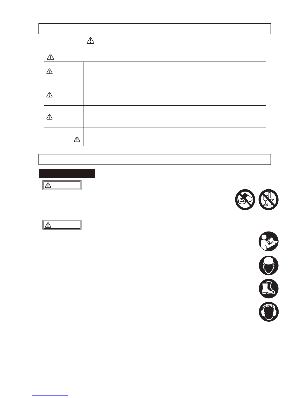
3.WARNING SIGNS
4.CAUTIONS FOR SAFETY
The triangle shaped marks used in this manual and on the decals stuck on the main body
indicate common hazards. Be sure to read and observe the cautions described.
Do not work with this machine, when
Please read the operation manual well and work safely by using the machine properly.
For handling of the engine, please refer to the separate engine operation manual.
Please have a good understanding of the structure of this machine.
Make sure to do work start inspection, regular self inspection and specified self inspection.
To make your work safe, please use protective equipment (use specified helmet, protective shoes, etc.) and wear appropriate work clothes.
Always use noise protection equipment such as ear muffs or ear plugs.
Always check the machine to make sure it is in normal condition before operating the
machine.
The nameplates attached to the machine (nameplates showing operation method,
warning, etc.) are very important for your safety. Clean the machine so that the nameplates can be read easily. If it is difficult to read the nameplate, please replace the old
one with a new one.
It is dangerous for young children to come near the machine. Please pay careful attention to the method of storing and the storage location for this machine. Especially the
engine start key has to be taken out every time you finish your work, and keep it in a
designated location.
To do maintenance work, stop the engine and remove the battery wiring.
We are not responsible for accidents that have occurred after the machine was refurbished without approval from the manufacturer.
you are tired or sick and not feeling well,
you have taken medicine or drug, or
you have had a drink.
4.1 General Cautions
●
●
●
●
●
●
●
●
●
●
●
●
○
○
○
Warning labels indicating hazards to humans and to equipment.
DANGER
!
WARNING
!
CAUTION
!
CAUTION
!
Denotes an extreme hazard. It calls attention to a procedure, practice,
condition or the like, which, if not correctly performed or adhered to, is
likely to result in serious injury or death.
Denotes a hazard. It calls attention to a procedure, practice, condition
or the like, which, if not correctly performed or adhered to, could
result in serious injury or death.
Denotes a hazard. It calls attention to a procedure, practice, condition
or the like, which, if not correctly performed or adhered to, could
result in injury to people and may damage or destroy the product.
Failure to follow the instructions may result in damage to property.
!
(without at )
WARNING
!
CAUTION
!
Page 8

3
Always refuel in a well ventilated area.
Make sure to stop the engine and wait until the engine cools down when refueling.
Select a flat surface area with no flammable material around for refueling. Be careful
not to spill the fuel. Wipe off well if there is any spill.
Never put fire near the machine during refueling. (Especially, be careful about
smoking.)
If you fill to the top of the fuel tank inlet, fuel might spill out from the tank, and it
becomes dangerous
After refueling, tighten the tank cap well.
Do not run the machine in an unventilated location, such as indoors or inside a tunnel. The exhaust gas
from the engine contains toxic gases such as carbon monoxide and is very hazardous.
Do not operate the machine near open flames.
Check each part to see if it is tightened properly. Vibration causes loosening of bolts, which results in
unexpected serious malfunctions of the machine. Tighten the bolts securely.
Before starting the machine, make sure it is safe to start by checking your surroundings for people and
objects.
Always pay attention to your footing. Work in an area where you can maintain a good balance of the
machine and a safe comfortable posture.
The engine and muffler become very hot. Do not touch immediately after the machine stops because
they are still very hot.
If you notice deterioration of machine operation during your work, stop your work immediately.
Before moving away from the machine, be sure to turn the engine off. Also when the machine is
transported, stop the engine and close the fuel cock.
For a machine with cell starter specification, do not operate without the battery. If you operate without the
battery, electrical system failure might occur.
Before lifting, check the machine parts (especially the hook and anti-vibration rubber) for any damage
and loosened or missing bolts.
Stop the engine and shut the fuel cock while lifting.
Use a sufficiently strong wire rope.
For lifting, use only one point hoisting hook, and do not lift at any other part.
When the machine is hoisted, never let people or animals come underneath.
For safety reasons, do not lift to a height that is higher than necessary.
Stop the engine during transportation.
Transport after the engine and the machine are cooled down.
Always drain the fuel before transporting.
Securely fix the machine to prevent it from moving or falling during transportation.
4.2 Refueling Precautions
4.4 Precautions Before Starting
4.5 Precautions During Work
4.6 Lifting Precautions
4.7 Transportation And Storage Precautions
4.3 Location And Ventilation Precautions
●
●
●
●
●
●
●
●
●
●
●
●
●
●
●
●
●
●
●
●
●
●
●
●
DANGER
!
DANGER
!
DANGER
!
WARNING
!
CAUTION
!
CAUTION
!
Page 9

4
Appropriate maintenance is required to ensure safe and efficient operation of the
machine. Always pay attention to the machine’s condition and keep it in good
condition. Pay special attention to the parts used for lifting, if they are not maintained
properly, it might result in a serious accident.
Start maintenance work after the machine has cooled down completely. The muffler,
in particular, becomes very hot, and there is a danger of burn. The engine, engine oil
and vibrator also become very hot. Be careful not to get burned.
Always stop the engine before inspection and adjustment. If you are caught in a
rotating part, serious injury might occur.
After maintenance work, check the security parts to see if they are securely installed.
Special attention should be paid when checking bolts and nuts.
If disassembly is involved in maintenance, refer to the maintenance instruction
manual to make your work safe.
If the battery fixing bolts have been removed, put them back and tighten securely to
fix the battery.
If used with the battery not fixed properly, contact with the battery terminal might
occur, leading to electric shock and electric leak, or breakage of the battery might
occur by the impact and vibration from outside, resulting in battery fluid leakage.
The gas from the battery might cause an explosion. Do not generate sparks or bring
flames near the battery.
Never put the positive terminal and negative terminal come into contact. Sparks will
be generated, and ignition might occur.
Be careful when handling the battery fluid because it is very toxic. If the battery fluid
gets on your skin, eye, or clothes, rinse it off with plenty of water and consult with a
doctor.
4.8 Maintenance Precautions
About The Battery
●
●
●
●
●
●
●
●
●
DANGER
!
WARNING
!
WARNING
!
CAUTION
!
Page 10
5
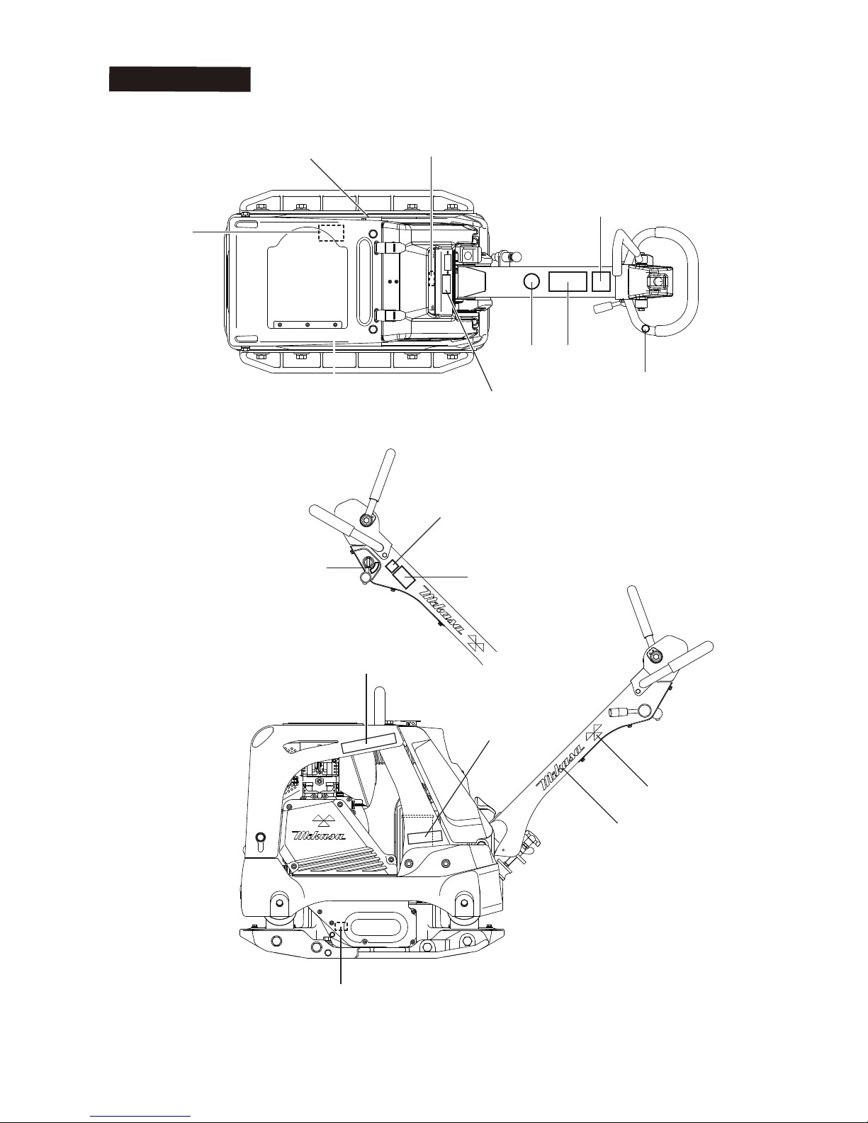
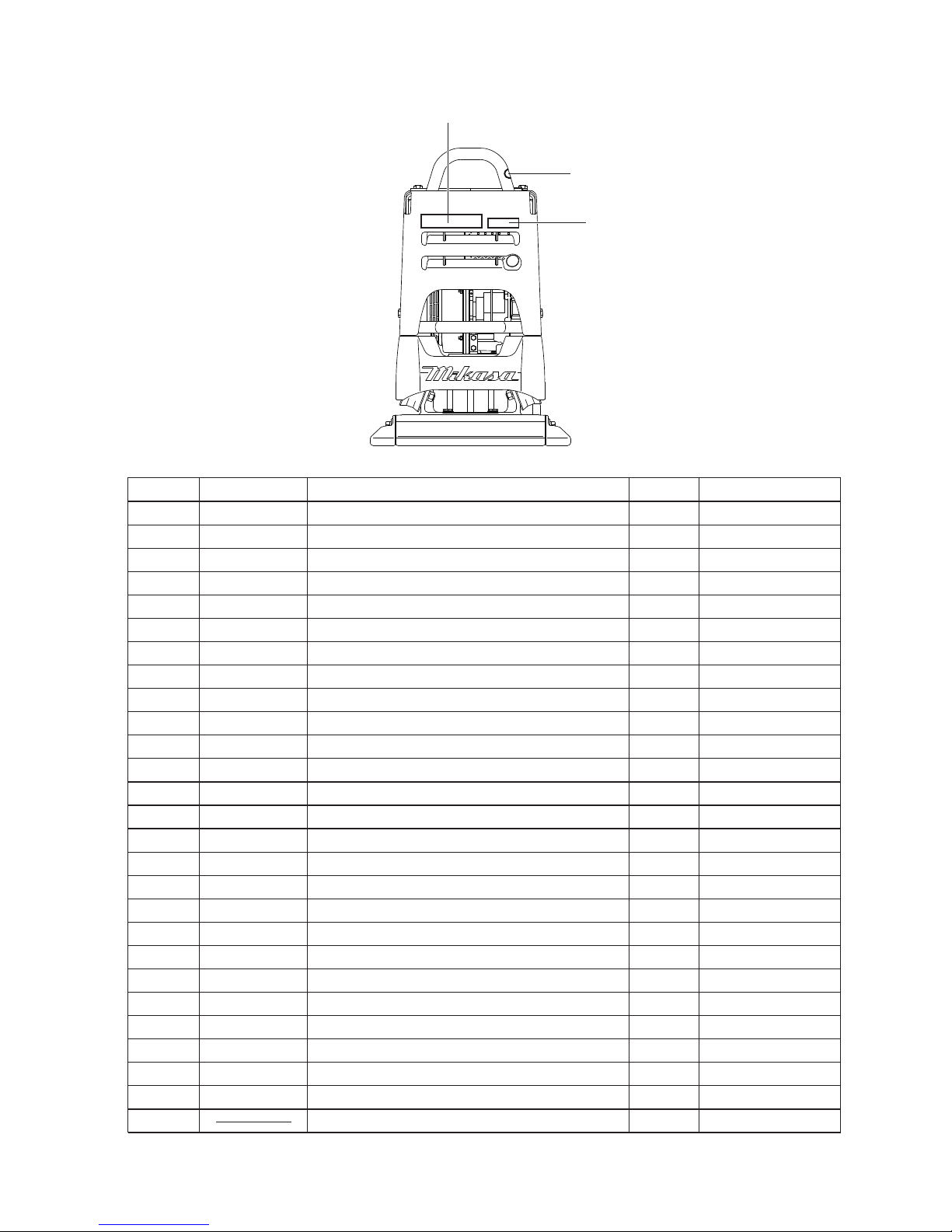
4.9 Label Position
2
18
17
1
7
15
15
14
5
16
3
4
6
10
12
13
※ The illustration is shown for model, "MVH-308"
Page 11
6
PART No. PART NAME Q’TY REMARKREF No.
9202-10100
9202-03330
9201-08800
9202-14960
9202-01950
9202-14950
9202-14730
9202-14740
9202-17640
9202-17650
9202-14750
9202-17130
9202-17110
9202-18140
9202-18130
9202-18150
9202-18160
9202-17870
9202-17880
9202-17890
9202-17730
9202-17770
9202-17810
9202-17740
9202-17780
9202-17820
Diesel Only
Diesel Only
308D
308G
408D,508D
408G
308
408
508
308
408
508
308
408
508
Not For Sale
1
1
1
1
1
1
1
1
1
2
1
2
2
1
1
1
1
1
1
1
2
2
2
1
1
1
1
1
2
3
4
5
6
7
8
9
10
11
12
13
14
14
14
14
15
15
15
16
16
16
17
17
17
18
DECAL,EC NOISE REQ.LWA108
EAR PROTECTION LABEL
DECAL, KEY SWITCH
DECAL, KEY OPERATION
DECAL,OIL SAE 10W-30
DECAL,REMOVE KEY
DECAL,DO NOT LIFTING
DEAL,LIFTING POSITION
DECAL COMPASS MARK 94MM
DECAL COMPASS MARK 110MM
DEAL,CAUTION ICONS/V-TYPE
DECAL,MIKASA MARK(W)200L
DECAL, MIKASA MARK 35X70
DECAL, E/G RPM 3400
DECAL, E/G RPM 3600
DECAL, E/G RPM 2400
DECAL, E/G RPM 3200
DECAL, MODEL MVH-308
DECAL, MODEL MVH-408
DECAL, MODEL MVH-508
DECAL,MODEL MVH-308 R-OR
DECAL,MODEL MVH-408 R-OR
DECAL,MODEL MVH-508 R-OR
DECAL,MODEL MVH-308 L-OR
DECAL,MODEL MVH-408 L-OR
DECAL,MODEL MVH-508 L-OR
PLATE,SERIAL NO.
9
8
16
Page 12

7
4.10 Descriptions Of Symbols Used On Warning Labels
Do not use.
(For rollers)
NPA-1473
Do not use.
(For rollers)
NPA-1475 NPA-1474
①Open Fuel Cock to start
②Turn Stop Switch to “I”(ON) position
③Close Choke Lever
④Pull Recoil Starter to start
⑤Return Choke Lever to open
①Return Throttle Lever fully until “O”(OFF) position
to stop work
②After cooling down enough, stop the engine to move Stop Switch to “O”(OFF) position
③Close Fuel Cock at the end
START
STOP
Starting, and stopping
P/N 9209-00110
DECAL, SET /MVH, MRH /EXP, EU
(NPA-1476 : “Diesel engine type
” is excluded.
)
(Refer to engine instruction manual for Diesel engine type)
①
②
③
④
⑤
⑥
⑦
⑧
⑨
⑩
Fire hazard
Stop the engine when refueling. Fire may
occur if a flame is near the tank fuel port.
⑧
Danger of hearing damage caused by
noise
Always use ear plugs while operating the
machine.
⑦
Be careful not to get burned.
Accidental burn may occur if you touch the hot
parts (engine, muffler, etc.) during operation or
immediately after the machine stops.
④
Be careful not to be caught in rotating parts.
Make sure the engine is stopped when removing the belt cover during a belt change.
③
Read the manual carefully.
Always read the operation manual and have
good understanding of operation before your
work.
①
Danger: poisonous exhaust gas
Carbon monoxide poisoning may occur if
the exhaust gas is inhaled. Do not operate
the machine in a poorly ventilated area.
②
⑩
⑨
NPA-1476
MVH-308GH
MVH-408GH
( )
⑤
Be careful not to approach danger
source.
During operation, Be careful not to approach
hot parts and rotating parts.
⑥
Refueling Hazard.
Don't fill the fuel tank while the engine is
running or hot.
Lifting position.
For lifting, use only one point hoisting hook,
and do not lift at any other part.
Do not lift the machine at this point.
Lifting by the handle is prohibited.
Page 13

8
4.11 Control Unit Positions And Names
※ The illustration is shown for model, "MVH-308"
NPA−1764
A
A
NPA−1765
Oil filler for vibration case
(with oil gauge)
Oil filler for engine
(without oil gauge)
Rubber cover
Fuel tank cap
(Fuel inlet)
Hour / tacho meter
Cyclone cleaner
Hand pump
Key switch
Breather plug
(with plug cap)
Handle lock
(Stored position)
Grip
Compaction sensor
(COMPASS)
Oil drain plug for vibration case
Battery
Grip for adjusting handle height
Handle
(Stored position)
Rear cover
Center cover
Front cover
Vibrating plate
Extension plate (option)
Hook
Engine
Stopper for rear cover
Handle (Working position)
Throttle lever
Forward
Neutral
Reverse
Direction control lever
(variable speed adjustable)
Engine switch
(ON-OFF)
MVH-308GH
MVH-408GH
Page 14

9
5.SPECIFICATION
Main Dimensions
Compacting Board
Weight
Engine
Parformance
1540
1030
445(595,745)
445(595,745)
860
345(360,375)
HATZ,1B30
Air-cooled 4-cycle
diesel engine
4.9/3300
6.7/3300
3350
○
73/4400
45/4600
0~27
6.1
1540
1030
445(595,745)
445(595,745)
860
341(356,371)
YANMAR,L70N6
Air-cooled 4-cycle
diesel engine
4.9/3600
6.7/3600
3600
○
73/4400
45/4600
0~27
Overall Length
Overall Height (Handle)
Overall Width
Width
Length
Operating Weight
Manufacturer/Type
Type Of Engine
Maximum Power
Set Engine Revolution
Electric Start
Vibrating Frequency
Centrifugal Force
Max. Traveling Speed
Hand Arm Vibration
(Ahv)
mm
mm
mm
mm
mm
kg
kw/min
-1
PS/min
-1
r.p.m
Hz/VPM
kN/kgf
m/min
m/sec
2
mm
mm
mm
mm
mm
kg
kw/min
-1
PS/min
-1
r.p.m
Hz/VPM
kN/kgf
m/min
m/sec
2
MODEL
MVH-308DSY
MVH-308DSY-PAS
MVH-308DSZ
MVH-308DSZ-PAS
MVH-408DSY
MVH-408DSY-PAS
MVH-408DSZ
MVH-408DSZ-PAS
MVH-508DSZ
MVH-508DSZ-PAS
1570
1030
500(650,800)
500(650,800)
900
408(423,438)
HATZ,1B50
Air-cooled 4-cycle
diesel engine
6.7/2500
9.1/2500
2350
○
73/4400
55/5600
0~28
4.7
1570
1030
500(650,800)
500(650,800)
900
407(422,437)
YANMAR,L100N2
Air-cooled 4-cycle
diesel engine
7.0/3200
9.5/3200
3200
○
73/4400
50/5100
0~27
1600
1070
650(800)
650(800)
900
525(540)
HATZ,1D81
Air-cooled 4-cycle
diesel engine
8.9/2500
12.1/2500
2350
○
69/4150
65/6600
0~29
5.5
※
The number in parentheses is the dimension of the “extension plate(option)” with.
“( )” : MVH-308,408: (standard type, wide type)
MVH-508: (wide type)
Main Dimensions
Compacting Board
Weight
Engine
Parformance
Overall Length
Overall Height (Handle)
Overall Width
Width
Length
Operating Weight
Manufacturer/Type
Type Of Engine
Maximum Power
Set Engine Revolution
Electric Start
Vibrating Frequency
Centrifugal Force
Max. Traveling Speed
Hand Arm Vibration
(Ahv)
MODEL
Page 15

10
※
The number in parentheses is the dimension of the “extension plate(option)” with.
“( )” : MVH-308,408: (standard type, wide type)
MVH-508: (wide type)
Main Dimensions
Compacting Board
Weight
Engine
Parformance
Overall Length
Overall Height (Handle)
Overall Width
Width
Length
Operating Weight
Manufacturer/Type
Type Of Engine
Maximum Power
Set Engine Revolution
Electric Start
Vibrating Frequency
Centrifugal Force
Max. Traveling Speed
Hand Arm Vibration
(Ahv)
mm
mm
mm
mm
mm
kg
kw/min
-1
PS/min
-1
r.p.m
Hz/VPM
kN/kgf
m/min
m/sec
2
MODEL
MVH-308GE
1540
1030
445(595,745)
445(595,745)
860
310(325,340)
HONDA,GX270
Air-cooled 4-cycle
petrol engine
6.3/3600
8.6/3600
3600
×
73/4400
45/4600
0~27
2.8
1570
1030
500(650,800)
500(650,800)
900
364(379,394)
HONDA,GX390
Air-cooled 4-cycle
petrol engine
8.7/3600
11.9/3600
3200
×
73/4400
55/5600
0~28
3.7
1540
1030
445(595,745)
445(595,745)
860
307(322,337)
ROBIN,EX27
Air-cooled 4-cycle
petrol engine
6.6/4000
9.0/4000
3600
×
73/4400
45/4600
0~27
3.8
MVH-308GH MVH-408GH
Remarks:
Vibration Level is in comply with EU Directive 2002/44/EC and the
value is shown as 3 axix min vibration level.
Test course (Crushed gravel) is in comply with EN500-4.
The above values are sublect to change in case that the machine
is modified or/and the required regulations change.
Page 16

11
6.APPEARANCE
A
NPA−1765
NPA−1764
A
A
NPA−1765
MVH-308 (
Standard:595mm, Wide:745mm
)
MVH-408 (
Standard:650mm, Wide:800mm
)
MVH-308: 445mm
MVH-408: 500mm
MVH-308
MVH-408
MVH-508
MVH-308: 880mm
MVH-408: 930mm
MVH-308: 1540mm
MVH-408: 1575mm
1210mm
1360mm
1250mm
1400mm
1040mm
1600mm
900mm
MVH-308: 860mm
MVH-408: 900mm
Working position
Stored position
※ The illustration is shown for model, "MVH-308"
Extension plate (option)
Working position
Stored position
Standard
Extension plate (OPTION)
A
NPA−1765
(
500mm)
650mm
800mm
Page 17

Always stop the engine before inspection
Fig. 1
Upper level
Lower level
(refil needed)
Oil gauge
Fig. 2
Oil inlet at the top
Fig. 3
600cc
Effective
Oil gauge
(19mm wrench)
Drain plug
(14mm wrench)
7.INSPECTION BEFORE OPERATION
Part inspection sheet before work start
Check point
Visual inspection
Front cover & center cover
Fuel tank
Fuel system
Fuel filter
Engine oil
Vibration case oil
V-belt for vibrator
Oil pressure pipe line system
Traveling lever & part of system
Operation of traveling lever, rink origin
Bolt, nuts
Crack、Skewness
Falling off、Breakage、Crack、Looseness and falling off of bolt & nuts
Leak、Quantity of oil、 Dirt
Leak
Dirt
Leak、Quantity of oil、 Dirt
Leak、Quantity of oil、 Dirt
Crack、Tension
Leak、Looseness、Crack、Abrasion
Falling off、Breakage、Crack、Looseness and falling off of bolt & nuts
Operation check、Permissible error
Looseness、Falling off
Check item
The check is details of engine is referred to engine instruction manual independently.
Set the engine on a level surface to check
the oil level.If the oil level is low, add oil.
(Fig.1)
Only lubrication can be done from the top
for HATZ engine (1B and 1D). (There is no
oil gauge.) (Fig.2)
Use the following engine oil.
When pouring oil from the top (for 1B and
1D), oil might overflow if large amount of oil
is poured at one time. So, pour slowly.
●
※
Set the machine on a level surface, then
remove the oil gauge of the vibrator. Check
the oil gauge to see if the oil is at the specified level. Use engine oil SAE10W-30 as
lubrication oil.
Recommended oil quantity is 600cc. (Fig. 3)
Stop the engine when refueling.
Do not expose to open flames while refueling.
Do not fill to the rim because the fuel might
spill.
Wipe off well if a spill occurs.
Use clean automotive gasoline or automotive
light oil appropriate for the engine. Let the
fuel run through a filter when refueling.
Fuel inlet is located under the rubber cover
at the front cover top portion.
The fuel tank cap is equipped with a lock
lever. Unlock this lever before opening the
cap. (Only for HATZ engine)
(Fig.4)
●
●
●
●
●
●
●
●
7.1 Engine Oil
7.2 Vibration Case Oil
7.3 Refueling
CAUTION
!
DANGER
!
Quality: Diesel engine oil, Grade CC or above
Gasoline engine oil, Grade SE or above
Viscosity: SAE No. 30 at 20°C and above (summer)
SAE10W-30
12
Page 18

8.OPERATION
Set the fuel cock lever to the “ON” position
to let the fuel flow. (Fig. 6)
In cold weather or when the engine does
not start easily, set the choke lever to the
“Start” position. This is not necessary when
the engine is already warmed up. (Fig. 7)
1
The height of the handle is adjustable for
your comfort.(Fig.5)
Adjusting Handle height
Loosen the wing nut.Turn the grip clockwise
to raise the handle or counter clockwise to
lower the handle.When the handle is raised
to the desired height, tighten the wing nut.
2
8.1 Starting
Gasoline Engine
7.4 Handle
13
Fig. 4
Lock lever
Fuel tank cap
※
Only for HATZ engine
①
②
③
Put your finger at the lock lever
to pull it up towards you.
Unlock the lock lever.
Put your fingers to the tabs at
the two locations of the tank
cap to pull up towards you.
Grip
Wing nut
Fig. 5
Fig. 6
“ON”
Fuel cock lever
Fig. 7
Choke lever
Choke lever
“START”
“START”
“ON”
Fuel cock lever
HONDA (GX270,GX390) HONDA (GX270,GX390)
ROBIN (EX27) ROBIN (EX27)
Page 19

Move the throttle lever to the idle position.
(Fig. 8)
When the engine is stopped, the hour
tachometer is always showing "Cumulative
time".(Fig.9)
Turn on the engine switch on the rear cover.
(Fig.10)
Hold the recoil starter grip, and pull it a little.
You will feel a slight resistance. Then, pull it
hard to run the engine. be careful not to pull
too hard, or the rope might break or come
off. Allow the starter rope to slowly move
back into the case while keeping the grip
grabbed. (Fig.11)
3
4
5
6
After the engine has started, while you hear
some explosion loud noise, gradually move
back the choke lever until it is wide open.
(Fig.12)
When the choke lever is set to “Start”,
gradually move it back toward the “Operation” direction while making sure the
engine revolution stabilizes.
After the engine has started, warm up the
engine at low speed for 2 to 3 minutes. This
is especially important in cold weather.
“Rotation number” is displayed during operation.(Fig.13)
7
8
9
14
Fig. 10
Fig. 11
Starter grip
Recoil starter
Fig.13
Rotation number
Cumulative time
ENGINE TACH
HOUR&METER
HRS
TP-22
ENGINE TACH
HOUR&METER
RPM
TP-22
Idle position
Throttle lever
Handle
Fig. 8
ENGINE TACH
HOUR&METER
HRS
TP-22
Fig. 9
Choke lever
“OPERATION”
“OPERATION”
Choke lever
HONDA (GX270,GX390)
ROBIN (EX27)
Fig. 12
Page 20

Set the fuel cock lever to the “ON” position
to let the fuel flow.(Fig. 14)
(
Only for YANMAR engine
)
Starter motor
Insert the key to the key switch.
Open the throttle lever to the idling position.
(Fig.15)
Turn the key to "Run" position. (Fig.16)
The buzzer starts. After "HA" is displayed on
hour tachometer, the display will change immediately to "Cumulative time".(Fig.17)
Turn the key further to the “START” position
to start the engine. After the engine is
started, take your hand off the key.(Fig.16)
After the engine revolution rises, the buzzer
stops.
“Rotation number” is displayed during operation.(Fig.18)
After the engine has started, warm up the
engine at low speed for 2 to 3 minutes. This
is especially important in cold weather.
When the engine does not start, do not run
the cell motor continuously for more than
five seconds. Move the key back to the
“RUN” position, then wait for about 10 seconds to restart.
While the engine is running, never turn the
key switch to the “START” position.
Recoil motor
Insert the key to the key switch.
Open the throttle lever to the idling position.
(Fig.15)
Turn the key to "Run" position. (Fig.16)
The buzzer starts. After "HA" is displayed on
hour tachometer, the display will change immediately to "Cumulative time".(Fig.17)
Hold the recoil starter grip, and pull it a little.
You will feel a slight resistance. Then, pull it
hard to run the engine. be careful not to pull
too hard, or the rope might break or come
off. Allow the starter rope to slowly move
back into the case while keeping the grip
grabbed. (Fig.19)
●
1
2
3
4
5
6
●
●
●
1
2
3
4
Diesel Engine
15
Starter grip
Recoil starter
Fig. 19
DIESEL
ENGINE TACH
&HOUR
METER
HRS
DIESEL
ENGINE TACH
&HOUR
METER
RPM
Fig.18
Rotation number
Cumulative time
Diesel Engine
Fig.16
DIESEL
ENGINE TACH
&HOUR
METER
DIESEL
ENGINE TACH
&HOUR
METER
HRS
Fig.17
"HA" is displayed at the
operation position, then
immediately it will change
to "Cumulative time".
HA: 1B30 or 1B50
YA: L70 or
L100
1081: 1D81
Stop position
Throttle lever
Handle
Idle position
Fig.15
CAUTION
Fig. 14
“ON”
Fuel cock lever
YANMAR (L70N,L100N)
Page 21

16
When this machine is used on ground that contains clay, the ground surface tends to stick to
the vibrating board, and the machine travel
speed becomes slower. In this case, check the
bottom of the vibrating board to see if there is
any clay adhered to the board.
This machine cannot perform well on clay
and other type of ground with a high water
percentage. Drying the ground is recommended to make the ground water percentage appropriate for the machine to get good
compacting performance.
If you want to suspend the work, to return
quickly to the idle position the throttle lever.
(Fig.22)
Compaction sensor (Compas) is a system
that uses acceleration sensor to show realtime soil stiffness with LED (light-emitting
diode) lights based on the number of compactions done.
This compaction sensor improves efficiency
of compaction work because it can prevent
the area already properly compacted from
being compacted more than necessary and
to identify the area where more compaction
is needed. The sensor also has a function to
detect abnormality such as vibration trouble
(insufficient vibration frequency), ground
trouble (soft soil) and functional issues.
(Fig. 23)
NOTE
What is shown by the compaction
sensor (Compass) is not the absolute
value of the soil stiffness.
When using the sensor, always calculate
appropriate soil stiffness by conducting
plate load test and dynamic load test
(FWD), etc. to calibrate the LED lighting
level with the actual measurement value.
3
4
Throttle lever
Handle
Idle position
Operation
position
Fig.22
When you move to the idle position the
throttle lever, please do not return to the operating position rapidly the throttle lever before
the rotational speed is possible fall.
CAUTION
!
8.3 Compaction Sensor (Compas)
Reverse
Neutral
Forward
Fig.21
Direction
control lever
Throttle lever
Handle
Idle position
Operation
position
Fig.20
After the engine has started, warm up the
engine at low speed for 2 to 3 minutes. This
is especially important in cold weather.
Do not pull the starter knob all the length of
the rope.
After engine start, do not let the starter knob
off your hand, but return it slowly by holding it.
If you let the knob off at the position where it
is pulled, the rope retracts suddenly, leading
to breakage of the recoil starter and engine.
While the engine is running, never turn the
key switch to the “START” position.
During operation, pay sufficient attention to
dangerous objects, obstacles, in the direction of your work and surrounding area.
While in operation, never touch the moving
parts and high temperature parts of the machine.
If the throttle lever is opened suddenly, the
machine starts to operate. When you operate
the throttle lever slowly, it may cause failure
of the clutch causing the bad connection.
(Fig.20)
Use the back and forth movement direction
control lever to make the machine move
backward and forward. When the direction
control lever is pushed forward, the machine
moves forward, when pulled backward, the
machine moves backward.
At neutral, the machine vibrates staying at
the same location.(Fig.21)
5
●
●
●
●
●
1
2
CAUTION
8.2 Operation
CAUTION
!
Page 22

17
If that happens, because you cannot expect
sufficient compaction, do ground improvement work before proceeding with the compaction process. (Fig. 26)
Detection of vibration abnormality
During operation when appropriate vibration
frequency cannot be achieved because of
the specified engine revolution or the loosened drive belt, or when the vibration frequency is too high, it is indicated by the
flashing light. (Fig. 27)
Sensor wire disconnection
(Between acceleration sensor and sensor
panel)
If flashing of red LED and green LED alternates as shown in the figure, please check
the sensor wire because there is a possibility that it is disconnected. (Fig. 28)
Power cable disconnection
(Between battery and sensor panel)
If there is no power even when the key
switch is turned on, please check because
there is a possibility that the power cable is
disconnected.
Function to detect electric system abnormality
3-2
4
4-1
4-2
1
2
3
4
5
6
7
8
!
CM-01
Ground trouble or soft ground
(Red only: Lighted)
Compaction Analyzing System
Fig.26
1
2
3
4
5
6
7
8
!
CM-01
Compaction Analyzing System
Vibration abnormality due to insufficient revolution
(Green: Flashing)
Fig.27
(Red: Flashing)
(Alternating)
(Green: Flashing)
4
5
6
7
8
!
CM-01
4
5
6
7
8
!
CM-01
Fig.28
Function to detect abnormality
Normal compaction (during compacting)
Green LED lights up when the sensor finds
that the machine is in normal compaction
process. When the revolution goes up, and
compaction starts, the yellow LED ① lights
up, and as the compaction proceeds, the
number of the lighted LEDs increases from
②
to ⑧. After the LED light that was calibrated with the measured soil stiffness
value lights up, the compaction process
completes. (Fig. 24)
Normal compaction (Compaction limit)
Compaction limit is reached when all the
yellow LEDs from ① to ⑧ have lit up and
the red LED lights up. At this point, this machine cannot do any further compaction. If
higher soil stiffness value is required, please
use a machine of higher level. (Fig. 25)
Detection of ground trouble and soft ground
For a case of unstable ground or soft
ground (soil containing clay) for which the
use of this machine is not suitable, only the
red LED lights up, with no yellow LED illuminated.
1
2
3
3-1
Normal operation (Green: Lighted)
Vibration abnormality (Green: Flashing)
Compaction condition (Yellow (1 - 8): Lighted)
Compaction limit (Yellow + Red: Lighted)
Soil problem (Only red: Lighted)
1
2
3
4
5
6
7
8
!
CM-01
Compaction Analyzing System
Fig.23
Normal operation (Green: Lighted)
Initial compaction (Yellow ①: Lighted)
1
2
3
4
5
6
7
8
!
CM-01
Compaction Analyzing System
Fig.24
During compaction (Yellow ① to ④ : Lighted)
1
2
3
4
5
6
7
8
!
CM-01
Compaction Analyzing System
Fig.25
Page 23

Diesel Engine
18
34When the key switch is moved from “ON
(Operation)” to “OFF(Stop)”, the buzzer
stops. (Fig. 32)
Shut the fuel cock.(Fig. 33)
(
Only for YANMAR engine
)
Stop position
Throttle lever
Handle
Idle position
Fig.31
Fig.32
CAUTION
If the throttle lever is moved from the idling
position to the stop position, the engine revolution decreases. Before the engine stops
completely, do not move the throttle lever sud-
9.STOPPING THE MACHINE
Move the throttle lever to idle position.
Run the engine for 3 to 5 minutes at low
speeds to cool it down before stopping.
Turn the engine switch to the OFF position,
then the engine stops. (Fig. 29)
Shut the fuel cock.
(Fig. 30)
Move the throttle lever to idle position.
Run the engine for 3 to 5 minutes at low
speeds to cool it down before stopping.
Move the throttle lever to the stop position
to stop the engine.
In case of a diesel engine, when the engine
stops, the buzzer sounds.(Fig.31)
1
2
3
1
2
Fig.29
Gasoline Engine
Fig. 30
Fuel cock lever
“Close”
Fuel cock lever
HONDA (GX270,GX390)
ROBIN (EX27)
“Close”
Fig.33
YANMAR (L70N,L100N)
“Close”
Fuel cock lever
Page 24

19
10.TRANSPORTAION AND STORAGE
Make sure there is no breakage of guard
frame and anti-vibration rubber nor loosened or missing bolts.
Always stop the engine when lifting.
Use an intact wire rope without any deformation with sufficient strength.
Slowly lift upward without applying any
impact. Never let people or animals go
under the lifted machine.
For safety reasons, do not lift to a height
that is higher than necessary.
Use a crane for loading and unloading the
machine.
Designate a person to guide the loading and
unloading, and always work under the
instruction of that person.
When lifting, always use a hook. (Fig. 34)
Never lift by using the hook on the handle.
Stop the engine when the machine is transported.
Always drain the fuel before transportation.
Fix the machine securely to prevent the machine from moving or falling.
When putting the handle into the stored
condition (vertical condition), make sure it is
properly locked.
When transporting, remove the starter key.
Wash off dirt and soil from every part with
water. While washing, be careful not to let
the water splashed on the electric components such as the battery and the engine
muffler part.
●
●
●
●
●
1
2
3
●
●
●
●
●
●
●
●
●
●
Store in a dry area away from direct sunlight
after putting the cover over the machine to
prevent dust and dirt buildup.
Do not leave the machine outdoors. Keep it
indoors.
When not used for a long period of time,
drain the fuel from the fuel tank, and either
disconnect the battery terminal or remove
the battery itself.
When the machine is used after a long storage period, check the level of engine oil and
battery capacity.
10.1 Loading And Unloading
10.2 Transportation Precautions
10.3 Storage
WARNING
!
WARNING
!
Fig.34
Hook
Page 25

11.REGULAR CHECK AND ADJUSTMENT
11.1 Inspection And Maintenance Schedule Table
20
For details about the check and maintenance of the engine, please refer to the attached engine operation manual.
Caution: The above table shows the check frequency for standard condition.
The check frequency may vary depending on the condition in which the machine is used.
For check of bolt and nut looseness and tightening, please see the following tightening torque list.
Tightening torque list (unit: kgf-cm, 1kgf-cm=9.80665N-cm)
6mm
8mm 10mm
12mm 14mm
16mm 18mm 20mm
4T(SS41)
70
150
300
500 750
1,100
1,400
2,000
6-8T(S45C)
100
250
500
800 1,300
2,000
2,700
3,800
11T(SCM3)
150
400
800
1,200
2,000
2,900 4,200
5,600
When the mating material is aluminum.
100
300~350 650~700
Thread diameter
Material
(Bolts used on the machine are all right-hand thread.)
Check parts
Appearance
Fuel tank
Fuel system
Engine oil
Shock absorber
Hand pump
Vibrator oil
Hydraulic pipe system
Air cleaner
Guard frame
Back and forth motion
lever, linking parts
Back and forth motion
lever operation
Bolts and nuts
Duct hose
Engine oil
Engine oil filter
Engine oil
Engine oil filter
Vibrator oil
Hydraulic oil
Battery terminal
V-belt for vibrator
Clutch
Vibrator oil
Hydraulic oil
Fuel filter
Engine oil filter
Fuel
pipes
Air cleaner element
Hydraulic hose
Cyclone cleaner
Check frequency
Daily
(before starting)
Every 20 hours
Every 100 hours
Every 200 hours
Every 300 hours
Every 2 years
Irregular
Check items
Flaw, deformation
Leakage, oil level, dirt
Leakage, oil level, dirt
Leakage, oil level, dirt
Crack, damage, wear
Leakage
Leakage
Leakage, looseness,flaw,
wear
Dust on sponge
Breakage, flaw, loosenedor
missing bolts and nuts
Missing, breakage,
flaw,looseness or m
issing-
bolts and nuts
Operation check, play
Looseness, missing
Crack, damage
Replace only afterthe first
20 hours
Replace only afterthe first
20 hours
Change
Washing
Leakage, oil level, dirt
Leakage, oil level, dirt
Cleaning
Flaw, tension
Dirt, flaw, wear
Change
Change
Change
Change
Change
Change
Change
Cleaning
Oils
Light oil, gasoline
Engine oil
Hydraulic oil
Engine oil
Hydraulic oil
Engine oil
Engine oil
Hydraulic oil
Engine oil
Hydraulic oil
Page 26

For a comfortable maintenance work.
Do maintenance work in a place with a flat
and hard surface to keep the machine
stable.
Start your work after the machine and
engine cool down completely.
Be careful to catch the finger when opening
and closing the front cover.
Do not touch the hot part because the
engine and muffler become very hot.
Remove the bolts (M14x35) on the front
cover. Loosen the bolts (M14x35) on the
side of front cover. (Do not remove.) (Fig.35)
Hold the side of front cover, and pull up to
open position.(Fig.36)
Open the front cover slowly.(Fig.37)
●
●
●
●
1
2
3
Hold the hook and the front side of front
cover, and pull up to open position.(Fig.38)
Open the front cover slowly.(Fig.39)
Return the front cover to original position
slowly.Tighten the bolts in the specified
torque. (Fig.40)
Do not return the front cover in its open position.
Do not start the engine when opening the
front cover.
Tighten the bolts firmly.
2
3
4
●
●
●
21
11.2 Opening The Front Cover
CAUTION
!
Fig.38
Pull up
Fig.35
Top of front cover
bolts (M14×45)
Side of front cover
bolts (M14×45)
Fig.40
Front cover top
BOLTS (M14×45)
Side of front cover
BOLTS (M14×45)
Fig.37
OPEN
Fig.39
OPEN
CAUTION
!
Fig.36
Pull up
Diesel Engine
Gasoline Engine
Bolt M14X45
176.6N・m
(130.2ft・lbf)
Size
Apply Loctite
#243
Tightening
torque
Remarks
Open position
Open position
Page 27

22
Perform the first engine oil change after 20
hours of operation, then change at every
100 hours.(Fig.41)
The Engine Air Cleaner
When the air cleaner element becomes
dirty, the engine does not start smoothly,
and sufficient output cannot be obtained.
Machine operation will be affected and the
engine life will be shortened greatly. Do not
forget to clean the element. (For details,
please see the separate engine operation
manual.) If the element cannot be cleaned,
replace it with a new one.(Fig.42)
Cyclone Cleaner
Always clean Dust Pot. Clogged Dust Pot
leads to reduce cyclone effect with easy
wear of Cleaner Element.
How to clean Dust Pot
Latch off to remove Dust Pot. (Fig.43)
●
●
●
i)
ii)
iii)
1
2
●
11.3 Changing The Engine Oil
11.4 Cleaning The Air Cleaner
11.5 Checking/Changing The V-belt
And Clutch
Clean Dust Pot inside with water and neutral detergent.
Latch up securely to return Dust Pot to Air
Cleaner.(Fig. 44)
Check of V-belt (Fig. 45)
At every 200 hours, remove the belt cover
(top) to check the tension of the V-belt.
The flexibility of the belt should be about
10 mm when pushed strongly with your
finger at the mid-point between the axes.
When the V-belt is loose, the engine
power is not transmitted well, resulting in
poor compacting force and shortening the
life of the V-belt.
Changing the V-belt
Removing the V-belt
Remove the top and bottom belt covers.
Put a wrench (19mm) on the tightening
bolt of the vibrator pulley (lower side). Put
a piece of cloth at the center of the left
side of the V-belt, and pull the belt strongly
towards you. While pulling, turn the
wrench clockwise, then remove the V-belt.
Fig.44
1
2
Lock
Dust exhaust
Fig.41
Engine oil drain
(Drain bolt)
Fig.42
Engine air cleaner
Dust pot
Latch
Dust exhaust
Fig.43
CAUTION
!
Be careful to avoid pinched fingers.
CAUTION
!
Do not use organic solvent like paint thinner, which may cause damage or deformation of Dust Pot.
Clutch
V-belt
Vibration pulley
Fig.45
Page 28

●
●
●
●
●
●
●
●
●
1
2
23
11.6 Checking/Changing The vibrator Oil
11.7 Checking/Changing The Hydraulic Oil
Installing the V-belt
Set the V-belt on the lower side of the vibrator pulley. Push the V-belt to the left side of
the upper clutch. Similar to removing the
V-belt, turn the wrench clockwise to install.
Stop the engine when inspecting or changing the V belt.
Be careful not to have your hand or clothes
get caught between the V belt and the
clutch. Always wear work gloves.
At every 100 hours of operation, set the
machine on a level surface and remove the
oil gauge of the vibrator. Check the oil level
to see if it is within the allowable range.
(Fig.46)
Change the vibrator oil at every 300 hour
operation. Drain the oil from the drain plug.
For draining, put a beam under the compacting board at the other side of the drain
plug to tilt the machine.
Use engine oil SAE 10W-30 as lubrication oil.The quantity used is 600cc.
Appropriate maintenance is required to
ensure safe and efficient operation of the
machine. Pay special attention to the parts
used for lifting, if they are not maintained
properly, it might result in a serious accident.
When checking the vibrator oil, clean the
oil port beforehand to prevent dust and
other foreign materials from falling into the
oil. Whenever there is an oil leakage from
the vibrator, check the oil level.
In case that oil is drained from Drain Plug,
some oil still remains in Oil Pan. So be
sure to check oil level correctly by Oil
Gauge after filling oil.
Do not fill oil with excessive volume
(600cc). It may cause the terrible fuel consumption and lower machine performance
as the result of engine overload.
Check the hydraulic oil
Check the hydraulic oil at every 100 hours’
operation. By making the handle bar vertical (done at the time of storage), remove
the breather plug at the top of the hydraulic hand pump to see if the hydraulic oil is
at the specified level (OIL LEVEL).
(Fig. 47)
Changing the hydraulic oil
Remove the plug cap of the hand pump.
Then remove the breather plug (with
24mm wrench) before removing the hydraulic hose connected to the cylinder on
the vibrator side. Set the run lever to
reverse, then drain the hydraulic oil from
the pump.(Fig.47, 48)
After the oil is drained, attach the hydraulic
hose again to the cylinder on the vibrator
side. With the direction control lever at the
forward-most position, fix to the hook with
a rope to immobilize.
(Fig.48, 49)
CAUTION
!
CAUTION
!
Fig.46
600cc
Effective
Oil gauge
(19mm wrench)
Drain plug
(14mm wrench)
Fig.48
Air releasing plug
Cylinder
Hydraulic hose
Fig.49
Direction
control lever
Hook
Forward-most position
Fig.47
Breather
plug
Plug cap
OIL LEVEL
Hand pump
Page 29

3
4
5
6
●
●
●
1
2
3
4
24
11.8 Battery
How to remove the battery
Remove the stopper at the two locations
on the top portion of the rear cover to
open the rear cover.(Fig.51)
Loosen, but not remove, the M8 bolts (2
bolts) used for cyclone cleaner attachment. Take out the cyclone cleaner downward.(Fig.52)
Take off the nuts and remove the battery
holder. After tilting the battery backward,
disconnect the battery terminal. When
doing so, always disconnect the black terminal on the minus side first.
By holding the top surface handle, pull
upward to remove the battery from the
machine.(Fig.53)
If an old battery is used, even when the battery checker is not lighted (indicating charging
level low), the cell starter might not operate
because of low charging level. If that happens, change the battery with the new one.
Pay sufficient attention so that the battery terminal will not touch the frame.
Pour hydraulic oil(550cc) from the hand
pump breather plug attachment hole.
(Fig.47)
Remove the air releasing plug of vibrator
cylinder. Then oil will come out from the
air releasing plug. After air bubbles stop
coming out, attach the plug. Tighten securely. (Fig.48)
Then release the direction control lever
and move the lever forward and reverse
several dozen times (until air bubble not
be found). Stay the lever at the forward
position for 10 seconds every time.
(Because the check valve is opened at the
maximum forward position and air bubble
will come out from the oil tank of the hand
pump).(Fig.49)
In case the air bleeding is insufficient,
repeat the procedure of above “4” and “5”.
Attach the hand pump breather plug, put
on the plug cap. After making sure the hydraulic oil in the pump is at OIL LEVEL,
attach the breather plug.
Hydraulic oil:
Shell Terrace Oil #32 or equivalent
Checking the battery
The standard battery installed is a maintenance free battery. It is not necessary to
supply battery fluid. In case of a sudden
voltage drop, the battery cannot be
charged quickly, so it has to be replaced
with a new one.
Check of battery capacity by battery
checker
When the battery charging level gets low,
the battery checker of the hour tachometer
lights up in red.(Fig.50)
The level of the hydraulic oil in the hand pump
should always be at OIL LEVEL. If the level is
higher, the oil bursts out from the breather plug.
CAUTION
!
CAUTION
!
CAUTION
!
Fig.51
Rear cover
Stopper
Fig.50
DIESEL
ENGINE TACH
&HOUR
METER
Battery checker
HOUR TACHOMETER
Fig.52
M8 bolts (2 bolts)
CUT
Cyclone cleaner
Page 30

5
25
For assembly, take the reverse steps described above, but when attaching the battery terminal, start with the red terminal of
the plus side. Also, attach securely so that
it will not get loosened by vibration.
When charging the battery, always
remove it from the machine.
CAUTION
!
Nut
Battery holder
Battery
Handle
Fig.53
MVH-308
L W H SIZE
MVH-408
MVH-508
129
175
175
129
175
129
175
175
175
175
175
175
175
175
203
175
190
203
190
203
203
175
190
203
203
175
190
203
55B24L(JIS) No.51R(BCI)
DIN 55Ah or equivalent
55B24L (JIS) No.51R(BCI)
※
75D23L(JIS) No.35(BCI)
DIN 55Ah or equivalent
75D23L(JIS) No.35(BCI)
DIN 75Ah or equivalent
JIS/BCI TYPE Maximum capacity
DIN TYPE Maximum capacity
Maximum capacity
Maximum capacity
STD
Replacement
STD
Replacement
STD
Replacement
238
245
245
245
245
238
232
245
245
245
232
245
245
245
6 Mountable battery size table
Page 31

12.TROUBLESHOOTING
12.1 Gasoline Engine
(1) Starting problems
(2) Operation problems
(3) Recoil starter problems
26
Fuel is supplied, but
the igniter plug does
not ignite.
Electricity reaches
the high voltage cable.
Electricity does not
reach the high
voltage cable.
Bridging the igniter plug.
Carbon accumulated on the igniter plug.
Short circuit due to insulation problems of
the igniter plug.
Inappropriate spark gap
Short circuit of the ON-OFF switch
Ignition coil problems
Dirt of the point or inappropriate gap.
Breakage of ignition coil or short circuit
The wrong fuel is used.
Mixing of water or foreign materials
The air cleaner not working
Intake/exhaust valve is stuck or pushed up
Piston ring, cylinder wear
Cylinder head, igniter plug tightening problem
Head gasket, igniter plug gasket breakage
Dirt of air cleaner.
Carbon accumulated in the cylinder.
Carburetor oil level inappropriate.
Compression is
good,
No fuel in the fuel tank.
Fuel cock does not open properly.
Clogging of fuel filter.
Clogging of tank cap air hole
Air trapped in the fuel pipe.
Compression is
not good,
Fuel supplied, and
the igniter plug
ignites.
Fuel does not reach
the carburetor.
Compression is
good and no firing
problem.
Insufficient compression (see the item “compression is not good.” )
Compression is
good, but no firing.
Water mixed in fuel
Dirt of the igniter plug.
Ignition coil problem
Occasional short circuit of the ignition coil
Lowered power.
Engine overheating
Carbon accumulated inside combustion chamber and exhaust hole.
Spark plug thermal value inappropriate
Dirt and breakage of the cooling fin.
Revolution fluctuation
Governor adjustment inappropriate
Governor spring problems
Fuel does not flow properly.
Air taken from intake pipe system
Recoil starter operation not good
Clogging of foreign materials at the rotating part.
Weakening of the spiral spring
Page 32

12.2 Diesel Engine
(1) Starting problems
(2) Insufficient output and operation problems
27
(A) In case of compression problems
(B) In case of inappropriate fuel injection inside the combustion chamber
(C) Fuel and compression pressure appropriate, but the engine does not start.
Intake/exhaust valve upthrust
Decompressor adjustment problems
Contact with seat not close enough.
Piston ring wear
Cylinder wear
Cylinder, cylinder head mating surface problems
Nozzle seat looseness
Clogging of the tank cap air hole.
Clogging of the fuel filter
Fuel cock not open
Air inside the fuel pipe
Injection pump barrel, plunger stuck
Nozzle hole clogging
Nozzle needle stuck
No compression at all
Almost no compression
Fuel flow low or no flow
Fuel not injected inside
the combustion chamber
No fuel in the fuel tank
Mixing of water or foreign materials
Does not reach
the starting revolution.
Insufficient compression
Engine overheating
with black smoke
Revolution fluctuation
Inappropriate starting operations
Engine oil viscosity high, engine oil is very dirty.
Air trapped inside the fuel pipe.
See the comment for insufficient compression.
Dirt and breakage of cooling fin
Mixing of water inside the fuel filter
Carbon accumulated in the combustion chamber or exhaust hole.
Smoke set inappropriate
Overload
Inappropriate injecting timing
Nozzle clogging
Governor fork and sleeve mating surface problems
Governor spring problems
Fly plate and sliding part wear and operation problems
Page 33

12.3 Main Body
28
Valve open/close timing inappropriate
Clogged exhaust hole, muffler
Overload
Piston, cylinder ring wear
Nozzle hole clogging
Piston ring stuck
Wrong assembly (upside down) of piston ring
Inappropriate injection timing
Inappropriate valve open/close timing
Looseness of injection pump joint
Leakage from fuel passage
Clogging of the air cleaner element
Inappropriate fuel due to mixing of impurities
Overload
Use of wrong oil
Failure to change oil
Breakage of the air cleaner element or failure to clean the air cleaner
Too much oil
Wrong assembly of the governor system
Detached injection pump rack
Insufficient engine output and inappropriate high speed set revolution
Slipping of clutch
Slipping of V-belt
Too much vibrator oil
Failure inside vibrator
Hand pump problems
Inappropriately installed forward/backward motion lever
Breakage of the oil hose
Mixing of air in the hydraulic oil
Clogging of foreign materials in the check valve inside the hand pump
Breakage of the piston bearing in cylinder
V-belt coming off, slipping and breakage
Slipping of the clutch
Locking of the vibrator
Breakage of the piston bearing in cylinder
Piston inside the hand pump not moving smoothly
Vibrator cylinder piston does not move smoothly
Firing problem with
white smoke
(when unloaded)
Fuel consumption too
high (black smoke)
Stopped suddenly with abnormal noise
Searing or damage of the piston, rod, etc.
Lubrication oil diluted and increased
.
Wear on the injection pump barrel or plunger
Engine does not stop
even though the fuel
supply is cut
(or over-running)
Low travel speed and
vibration weak
Move forward or
backwards, but unable
to switch between back
and forth motion
No forward,
backward motion
Movement of l
ever heavy
Engine revolution
does not increase.
Extensive wear on
sliding parts or
stuck piston rings
Page 34

G
114399-78260
55B24L
+
-
CB104
CA104
CB104
CA104
IG
ST
BAT
M8
JASO
D601
20T
DC12V 0.8kW
AV20
AV20
7122-2046
7123-2249
121252-39450
6040-2111
6030-2981
Compaction
sensor panel
Compaction sensor
G
Dynamo
Dynamo
114399-78260
White
White
White
White
White
Black
White
White
Red
Red
Red
Red
Red
Green
Green
Green
Starter
Starter
55B24L
Regulator
+
-
CB104
CA104
IG
ST
BAT
Starter switch
Starter switch
Battery
Battery
M8
BOLT
BOLT
AV1.25
AV1.25
AV1.25
White
Black
Black
Red
AV1.25
AV1.25
AV1.25
JASO
D601
20T
DC12V 0.8kW
AV20
AV20
YAZAKI
YAZAKI
YAZAKI
YAZAKI
7122-2046
7123-2249
Oil pressure switch
Oil pressure
switch
121252-39450
AV0.5(
Sky-blue
)
AV0.5(
Orange
)
AV0.5(
Sky-blue
)
AV0.5(
Orange
)
SUMITOMO
SUMITOMO
SUMITOMO
SUMITOMO
6040-2111
6030-2981
(Green/
White)
CB104 CB104
CA104
CA104
CB104
(Green/
White)
(Green/
White)
(Green/
White)
Palus
DC12V
(Black/
Green)
Hour/tacho meter
DC12V
CA104
CB104
CA104
CB104
Palus
(Black/Green)
(White)
CA104
(White)
Hour/tacho meter
Regulator
(Green/
White)
CB104 CB104
CA104
CA104
CA104
CB104
(Green/
White)
(Green/
White)
(Green/
White)
13.WIRING DIAGRAM
29
MVH-308DSY
MVH-408DSY
MVH-308DSY-PAS
MVH-408DSY-PAS
ISO 8820-3
TYPE,F
2A
(SAE J2077)
White
White
Red
Red
Green
Black
Page 35

30
CA104
CB104
(White)
Pulse
ISO 8820-3
TYPE,F
2A
(SAE J2077)
CB104
CA104
G
G
55B24L
30
50
15
30
50
15
AV20
AV20
AV20
AV20
55B24L
DC12V 1.0kW
CA104
CA104
CA104
CA104
CB104
CB104
CB104
+
-
+
-
Dynamo
Dynamo
Starter
Hour/tacho meter
Regulator
Regulator
Oil pressure
switch
Oil pressure
switch
Battery
Battery
Starter switch
Starter switch
Buzzer
(White)
Pulse
Black
Red
Green
Hour/tacho meter
Black
Red
Green
M8
BOLT
No.3: Relay drive
DC12V 1.0kW
Starter
M8
BOLT
No.3: Relay drive
Compaction
sensor panel
Compaction sensor
MVH-308DSZ
MVH-408DSZ
MVH-308DSZ-PAS
MVH-408DSZ-PAS
Buzzer
Page 36

31
75D23L
75D23L
CA104
CB104
(White)
Pulse
ISO 8820-3
TYPE,F
2A
(SAE J2077)
CB104
CA104
CA104
G
G
30
50
15
30
50
15
AV20
AV20
AV20
AV20
DC12V 1.0kW
CA104
CA104
CA104
CA104
CB104
CB104
CB104
+
-
+
-
Dynamo
Dynamo
Starter
Hour/tacho meter
Regulator
Regulator
Oil pressure
switch
Oil pressure
switch
Battery
Battery
Starter switch
Starter switch
Buzzer
(White)
Pulse
Black
Red
Green
Hour/tacho meter
Black
Red
Green
M8
BOLT
No.3: Relay drive
DC12V 1.0kW
Starter
M8
BOLT
No.3: Relay drive
Compaction
sensor panel
Compaction sensor
CA104
CB104
CA104
CB104
MVH-508DSZ
MVH-508DSZ-PAS
Buzzer
Page 37

memo
- - - - - - - - - - - - - - - - - - - - - - - - - - - - - - - - - - -
- - - - - - - - - - - - - - - - - - - - - - - - - - - - - - - - - - -
- - - - - - - - - - - - - - - - - - - - - - - - - - - - - - - - - - -
- - - - - - - - - - - - - - - - - - - - - - - - - - - - - - - - - - -
- - - - - - - - - - - - - - - - - - - - - - - - - - - - - - - - - - -
- - - - - - - - - - - - - - - - - - - - - - - - - - - - - - - - - - -
- - - - - - - - - - - - - - - - - - - - - - - - - - - - - - - - - - -
- - - - - - - - - - - - - - - - - - - - - - - - - - - - - - - - - - -
- - - - - - - - - - - - - - - - - - - - - - - - - - - - - - - - - - -
- - - - - - - - - - - - - - - - - - - - - - - - - - - - - - - - - - -
- - - - - - - - - - - - - - - - - - - - - - - - - - - - - - - - - - -
- - - - - - - - - - - - - - - - - - - - - - - - - - - - - - - - - - -
- - - - - - - - - - - - - - - - - - - - - - - - - - - - - - - - - - -
- - - - - - - - - - - - - - - - - - - - - - - - - - - - - - - - - - -
- - - - - - - - - - - - - - - - - - - - - - - - - - - - - - - - - - -
- - - - - - - - - - - - - - - - - - - - - - - - - - - - - - - - - - -
- - - - - - - - - - - - - - - - - - - - - - - - - - - - - - - - - - -
- - - - - - - - - - - - - - - - - - - - - - - - - - - - - - - - - - -
- - - - - - - - - - - - - - - - - - - - - - - - - - - - - - - - - - -
Page 38

Page 39

Page 40

HEAD OFFICE
No.4-3, Sarugakucho 1-chome,
Chiyoda-ku, Tokyo, 101-0064,
Japan
 Loading...