

Mikasa MVH-308, MVH-508, MVH-408 Service Manual
SERIES
MVH-308
MVH-408
MVH-508
SERVICE MANUAL
REVERSIBLECOMPACTOR

TABLE OF CONTENTS
3.1
3.2
3.3
3.4
3.5
3.6
3.7
3.8
3.9
5.1
5.2
8.1
8.2
8.3
8.4
8.5
9.1
9.2
9.3
9.4
9.5
9.6
9.7
9.8
9.9
10.1
10.2
10.3
1
2
2
2
2
2
3
3
3
5
5
9
9
10
11
18
21
21
22
22
23
23
24
24
25
28
29
30
...............................................................................................
............................................................................
........................................
...........................
..............................................................................
.................................................................................
...............................
........................................................
.....................................................................
.................................................................................
.....................................................................................
...................................................................
............................................................................................
..............
.................................................................................
...............................................................
.........................................................
..............................................................................
.......................................................................
.......................................................................
.......................................................................
..............................................
.......................................................
.....................................................
..................................................................................................
....................................................................................
........................................................................................
.............................................................................................
Work Site
Clothes And Protective
Cautions During Refuelinglothes And Protective
Prevention Of Burn And The Accident Of Getting Caught
Tools And Equipment
Handling Of Battery
Use Of Genuine Parts And Appropriate Oil And V-belt
Tightening Torque Of Bolts And Nuts
Disposal Of Waste Material
Appearance Check
Operation Check
How To Remove The Battery
Control Part
Main Body Part (Separation Of Engine Base And Vibrating Plate Assembly)
Vibrator Partontrol
Hand pump & Accumulator CP
Inspection and Maintenance Chart
Oil Application Table
Opening The Front Cover
Changing The Engine Oil
Cleaning The Air Cleaner
Checking/Changing The V-belt And Clutch
Checking/Changing The Vibrator Oil
Checking/Changing The Hydraulic Oil
Battery
Gasoline Engine
Diesel Engine
Main Body
1. INTRODUCTION
1
2. WARNING SIGNS
1
3. CAUTIONS FOR MAINTENANCE TO SECURE SAFETY
1
4. TOOLS
4
5. INSPECTION PROCEDURE
5
6. SPECIFICATION
6
7. CAUTIONS BEFORE MAINTENANCE WORK
8
8. DISASSEMBLY AND ASSEMBLY
9
9. REGULAR CHECK AND ADJUSTMENT
21
10. TROUBLESHOOTING
28
11. WIRING DIAGRAM
31
ࠉࠉ
1
1䠊INTRODUCTION
For correct operation, maintenance and service of Reversible Compactor, please read the separate operation manual
before your work for your safe work.
For the handling of engine, please read the separate engine operation manual and maintenance/service manual.
This service manual explains the maintenance standard and how to disassemble and assemble for Reversible Compac-
tor. Please read this service manual for a better understanding of the maintenance standard, the structure and function
of each part.
To improve the performance and quality of this machine, the change might be made in this machine without notice. If
you have any questions, please contact with our distributor. For parts list, Mikasa WEB parts list is available at our
homepage (http://www.mikasas.com/).
䖃
䖃
䖃
䖃
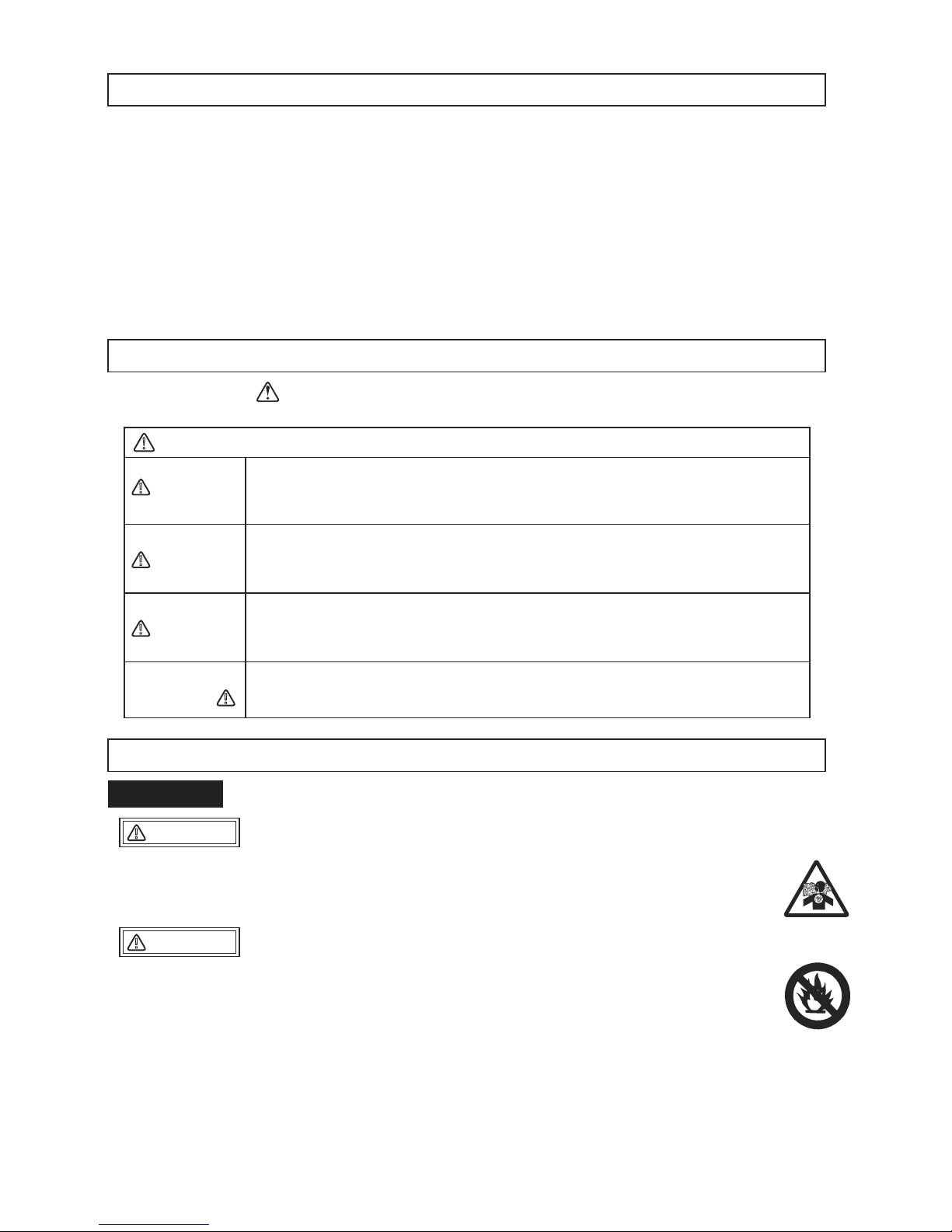
2䠊WARNING SIGNS
The triangle shaped marks used in this manual and on the decals stuck on the main body
indicate common hazards. Be sure to read and observe the cautions described.
Warning labels indicating hazards to humans and to equipment.
DANGER
䟿
WARNING
䟿
CAUTION
䟿
CAUTION
䟿
Denotes an extreme hazard. It calls attention to a procedure, practice,
condition or the like, which, if not correctly performed or adhered to, is
likely to result in serious injury or death.
Denotes a hazard. It calls attention to a procedure, practice, condition
or the like, which, if not correctly performed or adhered to, could
result in serious injury or death.
Denotes a hazard. It calls attention to a procedure, practice, condition
or the like, which, if not correctly performed or adhered to, could
result in injury to people and may damage or destroy the product.
Failure to follow the instructions may result in damage to property.
䟿
(without at )
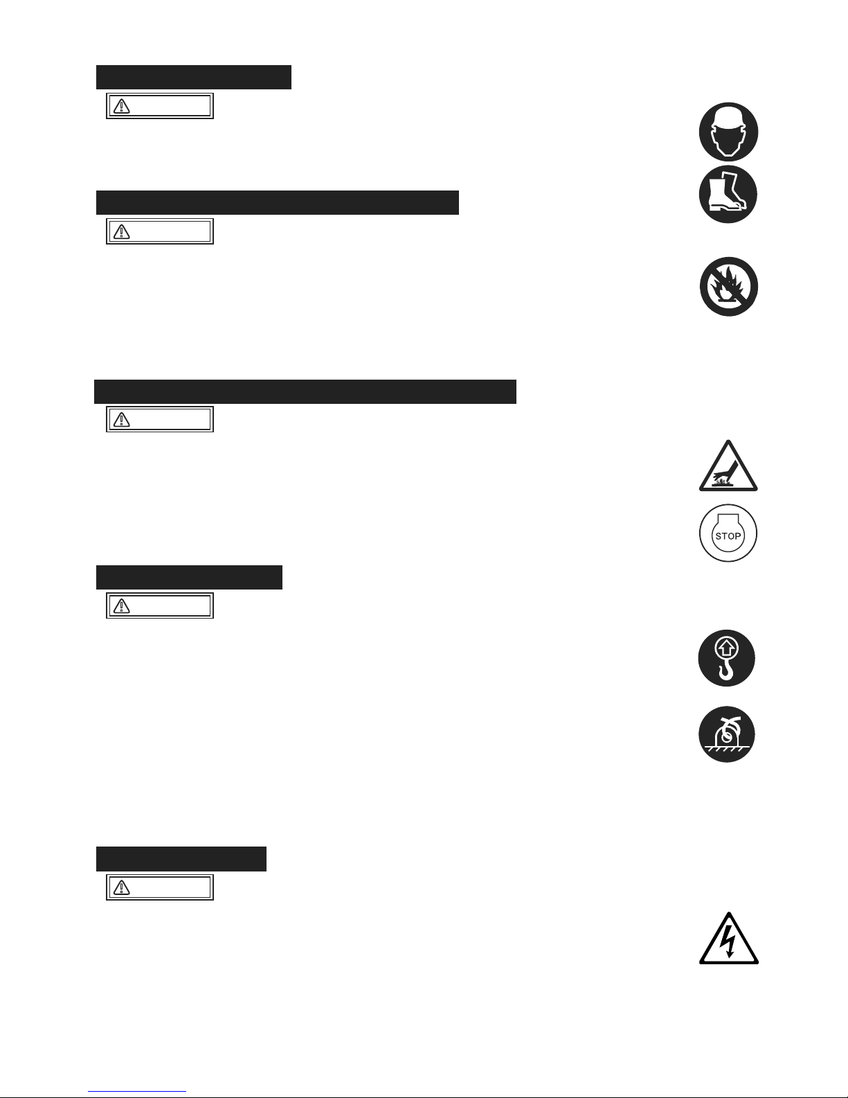
3䠊CAUTIONS FOR MAINTENANCE TO SECURE SAFETY
Do not work indoor or inside a tunnel where ventilation is poor. The emission from the
engine contains toxic gas such as carbon monoxide, and it is very dangerous if this
toxic gas and dust are inhaled. Also, to improve ventilation, please keep a proper
distance between this machine and a building when operating the machine.
Maintenance should be done in a place with a flat and hard surface to keep the
machine stable. Also, do maintenance at sufficient work space.
Before maintenance work, clean the floor. Oil on the floor, in particular, becomes the
cause of falling accident.
For maintenance work, have sufficient lighting in the work site. A portable lamp used to
illuminate the work area has to be protected by wire. In case if the lamp is broken, fuel
and oil might ignite.
To prepare for an accident, please have emergency medical supplies and fire
extinguisher ready at an easily accessible area.
3.1 Work Site
䖃
䖃
䖃
䖃
䖃
CAUTION
䟿
DANGER
䟿
2
To work safely, wear work clothes of appropriate size, and use suitable protective gear
such as helmet and safety shoes. The work clothes that do not fit the body size might
result in unpredicted injury because the clothes easily get caught by rotating part of the
machine.
When adding fuel
If fuel is filled to the top, it might overflow, and is dangerous.
After refueling, securely tighten the tank cap.
Start your work after the machine temperature drops. Especially, the muffler gets very
hot, and it will pose a danger of burn accident. Also, engine and engine oil as well as
vibrator become hot. Be careful not to get a burn.
If maintenance work is started with the engine running, injury might occur because you
might get caught by the rotating part such as pulley and V-belt. Always stop the engine
before maintenance.
Before maintenance work, remove the starter key of the engine.
Before starting maintenance, always remove the minus (-) terminal of the battery.
When lifting the machine body and the engine, always use a crane. When lifting the
machine and the engine, follow the cautions listed below. If the machine or the engine
is dropped, a serious accident might occur.
To operate a crane, a crane handling qualification is required. Have someone qualified
to handle and operate a crane do this work.
Before lifting, check the parts (especially, hook and anti-vibration rubber) of this
machine for damage and loosening/lack of bolts to secure safety.
Before lifting, stop the engine and shut the fuel cock.
Use sufficiently strong wire rope.
For lifting, use only the lifting hook. Do not use other part for lifting.
Never allow anyone or any animal come under the lifted machine.
For safety, do not lift to the height more than necessary.
Use an appropriate tool. If the tool that is not suitable for the part is used, not only the
damage on the part, but also unpredicted accident might occur.
Before starting maintenance, always remove the minus terminal of the battery. If short
circuit occurs, ignition might occur.
The battery gas might become a cause of explosion. Do not put fire nearby.
Especially, during charging, flammable gas is released. Do not put fire nearby.
The battery fluid is very toxic. Be careful when handling. If the battery fluid gets on your
skin, eye or on your clothes, wash it off with plenty of water, then see a doctor.
Always refuel in the well ventilated area.
Always refuel after the engine stopped and cooled sufficiently.
Select a flat surface location away from flammable material and Do not overfill
the tank. If spilled fuel, wipe it off well.
Never put fire near the refueling area. (Never refuel while smoking.)
3.2 Clothes And Protective
3.3 Cautions During Refuelinglothes And Protective
3.4 Prevention Of Burn And The Accident Of Getting Caught
䖃
䖃
䖃
䖃
䖃
䖃
䖃
䖃
䖃
䖃
䖃
䖃
䖃
䖃
䖃
䖃
䖃
䖃
䖃
䖃
䖃
WARNING
䟿
3.5 Tools And Equipment
WARNING
䟿
3.6 Handling Of Battery
WARNING
䟿
CAUTION
䟿
CAUTION
䟿
䕿
䕿
䕿
䕿

3
Always use genuine parts.
If inappropriate parts are used, not only it will shorten the machine life, but it might lead
to unpredicted accident.
Tighten bolts and nuts with the tightening torque specified in this maintenance manual.
Over tightening torque and lack of tightening torque not only affect the machine life, but
also might occur unexpected accident.
Unnecessary engine oil, hydraulic oil and fuel should be kept in a container. Never
dump it on the ground or pour into the sewage system such as side ditch.
For disposal of unnecessary engine oil, hydraulic oil and fuel, follow the law and other
regulations.
3.7 Use Of Genuine Parts And Appropriate Oil And V-belt
䖃
䖃
䖃
䖃
WARNING
䟿
CAUTION
䟿
3.9 Disposal Of Waste Material
CAUTION
䟿
3.8 Tightening Torque Of Bolts And Nuts
䠇
䞊
4
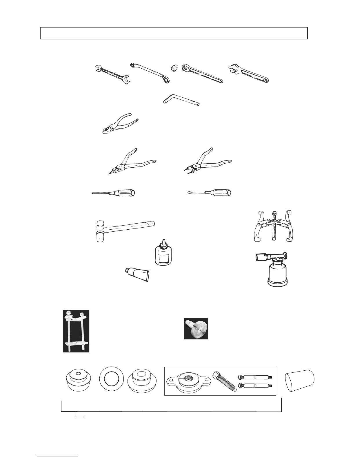
1. Wrench 10mm 12mm 13mm 14mm 17mm 19mm 22mm 24mm 27mm
Offset wrench/Socket wrench/Adjustable wrench
2. Hexagonal wrench 3/16inch
5mm 8mm 10mm 14mm
3. Plier
4. External snap ring plier/Internal snap ring plier(bent type can be also used)
6. Metal and plastic hammers 7. Pulley puller
9. Torch burner
8. Screw lock agent
(Locktite 242, 271 and 638)
10. Liquid gasket
11. Pressing machine
12. Special jig for hand pump disassembly and assembly
13. Special jig for vibrator disassembly and assembly
4䠊TOOLS
5. Screwdriver, flat and cross
9840-10060
Spring compression tool
9840-10040
Disassembling tool
9840-10070
9849-10011
Bearing insertion jig (driven shaft and drive one) set
Bearing
nsertion
cup
Bearing
insertion
ring
Bearing
insertion
holder
Bearing insertion puller
Bearing
remover

㻌
5
5.INSPECTION PROCEDURE
Assembly condition of each component (bolt loosening, defective parts, etc.)
Damage on machine body
Oil check (oil level, dirtiness)
V-belt check (tension, scratch, crack, deterioration, etc.)
Anti-vibration rubber check (scratch, crack, setting, deterioration, etc.)
Engine
Engine speed check (Operating speed, idling speed)
Travel
Check for abnormal noise during operation
Engine oil (when shipped, SAE10W30) (For oil level, please see the table below.)
Vibrator oil
Hydraulic oil (forward/backward travel)
Forward/backward travel switch check
Forward/backward travel speed check
5.1 Appearance Check
5.2 Operation Check
㻔㻝㻕
㻔㻞㻕
㻔㻟㻕
㻔㻠㻕
㻔㻡㻕
㻔㻝㻕
㻔㻞㻕
㻔㻟㻕
㼍㻚
㼎㻚
㼏㻚
㼍㻚
㼎㻚
Screw diameter
M6
M8
M10
M12
M14
The collar screws materials
SS,FCD
Aluminum
Aluminum type+Helisert
N.m
Kgf
.
cm
ft
.
lbf
N
.
m
Kgf
.
cm
ft
.
lbf
N
.
m
Kgf
.
cm
ft
.
lbf
N
.
m
Kgf
.
cm
ft
.
lbf
N
.
m
Kgf
.
cm
ft
.
lbf
11.8 - 14.7
120 - 150
8.7 - 10.8
24.5 - 29.4
250 - 300
18.1 - 21.7
58.8 - 68.6
600 - 700
43.4 - 50.6
98.1 - 107.9
1000 - 1100
72.3 - 79.6
117.7 - 127.5
1200 - 1300
86.8 - 94.4
14.7 - 17.7
150 - 180
10.8 - 13.0
32.4 - 35.3
330 - 360
23.9 - 26.0
73.5 - 78.5
750 - 800
54.2 - 57.9
112.8 - 122.6
1150 - 1250
83.2 - 90.4
166.7 - 176.5
1700 - 1800
123.0 - 130.2
Table 1
Standard torque table
MVH-308DSC
MVH-308DSC-PAS
MVH-308DSZ
MVH-308DSZ-PAS
MVH-308GE MVH-308GH MVH-408GH
MVH-408DSC
MVH-408DSC-PAS
MVH-408DSZ
MVH-408DSZ-PAS
MVH-508DSC
MVH-508DSC-PAS
L70V
L70N
YANMAR YANMAR
L100V
L100N
HATZ 1B30
HATZ 1D81
ROBIN EX27
HONDA GX270 HONDA GX390
HATZ 1B50
1,050cc
1,050cc 1,050cc
1,600cc 1,100cc
1,100cc
1,500cc
2,000cc
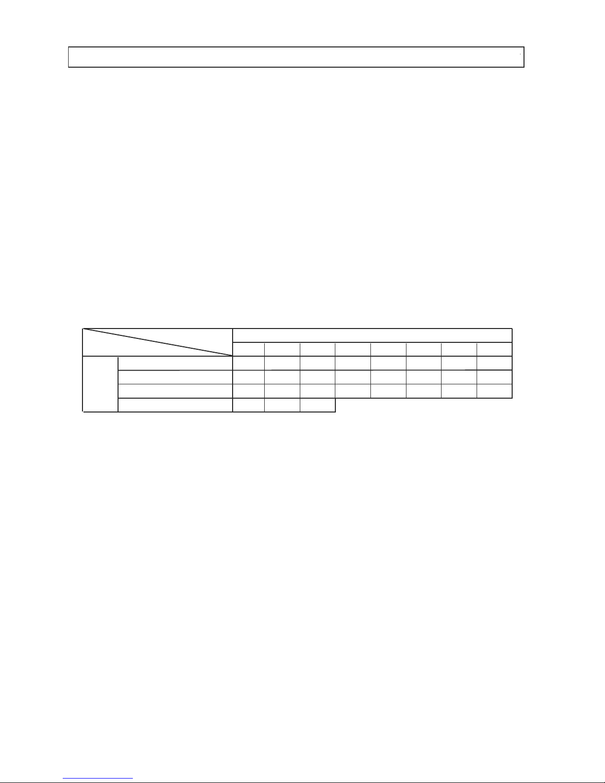
Capacity of Lubricant
for Engine
Model
Engine type
Capacity of Lubricant
for Engine
Model
Engine type
Engine oil level table Table 2

6
6䠊SPECIFICATION
Main Dimensions
Compacting Board
Weight
Engine
Parformance
1540
1030
445(595,745)
445(595,745)
860
345(360,375)
HATZ,1B30
Air-cooled 4-cycle
diesel engine
4.9/3300
6.7/3300
3350
○
73/4400
45/4600
0䡚27
6.1
1540
1030
445(595,745)
445(595,745)
860
341(356,371)
YANMAR,L70N6
Air-cooled 4-cycle
diesel engine
4.9/3600
6.7/3600
3600
○
73/4400
45/4600
0䡚27
Overall Length
Overall Height (Handle)
Overall Width
Width
Length
Operating Weight
Manufacturer/Type
Type Of Engine
Maximum Power
Set Engine Revolution
Electric Start
Vibrating Frequency
Centrifugal Force
Max. Traveling Speed
Hand Arm Vibration
(Ahv)
mm
mm
mm
mm
mm
kg
kw/min
-1
PS/min
-1
r.p.m
Hz/VPM
kN/kgf
m/min
m/sec
2
mm
mm
mm
mm
mm
kg
kw/min
-1
PS/min
-1
r.p.m
Hz/VPM
kN/kgf
m/min
m/sec
2
㻹㻻㻰㻱㻸
㻹㼂㻴㻙㻟㻜㻤㻰㻿㼅
㻹㼂㻴㻙㻟㻜㻤㻰㻿㼅㻙㻼㻭㻿
㻹㼂㻴㻙㻟㻜㻤㻰㻿㼆
㻹㼂㻴㻙㻟㻜㻤㻰㻿㼆㻙㻼㻭㻿
㻹㼂㻴㻙㻠㻜㻤㻰㻿㼅
㻹㼂㻴㻙㻠㻜㻤㻰㻿㼅㻙㻼㻭㻿
㻹㼂㻴㻙㻠㻜㻤㻰㻿㼆
㻹㼂㻴㻙㻠㻜㻤㻰㻿㼆㻙㻼㻭㻿
㻹㼂㻴㻙㻡㻜㻤㻰㻿㼆
㻹㼂㻴㻙㻡㻜㻤㻰㻿㼆㻙㻼㻭㻿
1570
1030
500(650,800)
500(650,800)
900
408(423,438)
HATZ,1B50
Air-cooled 4-cycle
diesel engine
6.7/2500
9.1/2500
2350
○
73/4400
55/5600
0䡚28
4.7
1570
1030
500(650,800)
500(650,800)
900
407(422,437)
YANMAR,L100N2
Air-cooled 4-cycle
diesel engine
7.0/3200
9.5/3200
3200
○
73/4400
50/5100
0䡚27
1600
1070
650(800)
650(800)
900
525(540)
HATZ,1D81
Air-cooled 4-cycle
diesel engine
8.9/2500
12.1/2500
2350
○
69/4150
65/6600
0㹼29
5.5
※
The number in parentheses is the dimension of the „extension plate(option)‰ with.
„( )‰ : MVH-308,408: (standard type, wide type)
MVH-508: (wide type)
Main Dimensions
Compacting Board
Weight
Engine
Parformance
Overall Length
Overall Height (Handle)
Overall Width
Width
Length
Operating Weight
Manufacturer/Type
Type Of Engine
Maximum Power
Set Engine Revolution
Electric Start
Vibrating Frequency
Centrifugal Force
Max. Traveling Speed
Hand Arm Vibration
(Ahv)
㻹㻻㻰㻱㻸

7
※
The number in parentheses is the dimension of the „extension plate(option)‰ with.
„( )‰ : MVH-308,408: (standard type, wide type)
MVH-508: (wide type)
Main Dimensions
Compacting Board
Weight
Engine
Parformance
Overall Length
Overall Height (Handle)
Overall Width
Width
Length
Operating Weight
Manufacturer/Type
Type Of Engine
Maximum Power
Set Engine Revolution
Electric Start
Vibrating Frequency
Centrifugal Force
Max. Traveling Speed
Hand Arm Vibration
(Ahv)
mm
mm
mm
mm
mm
kg
kw/min
-1
PS/min
-1
r.p.m
Hz/VPM
kN/kgf
m/min
m/sec
2
㻹㻻㻰㻱㻸
㻹㼂㻴㻙㻟㻜㻤㻳㻱
1540
1030
445(595,745)
445(595,745)
860
310(325,340)
HONDA,GX270
Air-cooled 4-cycle
petrol engine
6.3/3600
8.6/3600
3600
×
73/4400
45/4600
0㹼27
2.8
1570
1030
500(650,800)
500(650,800)
900
364(379,394)
HONDA,GX390
Air-cooled 4-cycle
petrol engine
8.7/3600
11.9/3600
3200
×
73/4400
55/5600
0㹼28
3.7
1540
1030
445(595,745)
445(595,745)
860
307(322,337)
ROBIN,EX27
Air-cooled 4-cycle
petrol engine
6.6/4000
9.0/4000
3600
×
73/4400
45/4600
0㹼27
3.8
㻹㼂㻴㻙㻟㻜㻤㻳㻴 㻹㼂㻴㻙㻠㻜㻤㻳㻴
Remarks:
Vibration Level is in comply with EU Directive 2002/44/EC and the
value is shown as 3 axix min vibration level.
Test course (Crushed gravel) is in comply with EN500-4.
The above values are sublect to change in case that the machine
is modified or/and the required regulations change.
8
Disassembly and assembly of this machine, with inspection and change of vibrator oil
included, should be done on a horizontal surface area. Before disassembly and
assembly, understand well the normal assembly condition so that you will not make
assembly error.
If oil seal, gasket, packing, O-ring or lock washer is disassembled, replace it with a new
one each time.
The contact surface between vibrator case and vibrator top cover should be sealed with
O-ring. (Clean the contact surface and be careful about O-ring position when
assembling.)
When tightening bolts and nuts, tighten them according to the specified standard torque
and applying the screw lock agent (Loctite, etc.). For bolts and nuts with no
specification, refer to the “Tightening torque list”. (When applying screw lock agent,
degrease and clean the screw part with the brake cleaner, etc.)
Note) The bolts used on this machine are all of the right hand thread.
When disassembling and assembling, work in the maintenance shop without dirt and
dust.
When the bolts applied the screw lock agent (Loctite, etc.) are difficult to loosen, they
loosen easily by heating them with a torch burner. Then, replace the heated bolt with a
new one. It should be a specified high tension bolt (genuine parts).
Use correct tools correctly.
First of all, the machine with battery remove the minus terminal before starting
disassembly. After assembly is done completely, install the minus terminal.
1.
2.
3.
4.
5.
6.
7.
8.
7䠊CAUTIONS BEFORE MAINTENANCE WORK
Tightening torque list
To change the unit to kgf・cm, convert with 1 N・m = 10.197 kgf・cm.
㻔㼡㼚㼕㼠㻦㻌㼗㼓㼒㻙㼏㼙㻘㻌㻝㼗㼓㼒㻙㼏㼙㻩㻥㻚㻤㻜㻢㻢㻡㻺㻙㼏㼙㻕
㻢㼙㼙
㻤㼙㼙 㻝㻜㼙㼙
㻝㻞㼙㼙 㻝㻠㼙㼙
㻝㻢㼙㼙 㻝㻤㼙㼙 㻞㻜㼙㼙
㻠㼀㻔㻿㻿㻠㻝㻕
㻣㻜
㻝㻡㻜
㻟㻜㻜
㻡㻜㻜 㻣㻡㻜
㻝㻘㻝㻜㻜
㻝㻘㻠㻜㻜
㻞㻘㻜㻜㻜
㻢㻙㻤㼀㻔㻿㻠㻡㻯㻕
㻝㻜㻜
㻞㻡㻜
㻡㻜㻜
㻤㻜㻜 㻝㻘㻟㻜㻜
㻞㻘㻜㻜㻜
㻞㻘㻣㻜㻜
㻟㻘㻤㻜㻜
㻝㻝㼀㻔㻿㻯㻹㻟㻕
㻝㻡㻜
㻠㻜㻜
㻤㻜㻜
㻝㻘㻞㻜㻜
㻞㻘㻜㻜㻜
㻞㻘㻥㻜㻜 㻠㻘㻞㻜㻜
㻡㻘㻢㻜㻜
When the mating material is aluminum.
㻝㻜㻜
㻟㻜㻜䡚㻟㻡㻜 㻢㻡㻜䡚㻣㻜㻜
㼀㼔㼞㼑㼍㼐㻌㼐㼕㼍㼙㼑㼠㼑㼞
Material
(Bolts used on the machine are all right-hand thread.)
9
1
3
4
5
7
12
8
9
10
11
13
2
3
4
5
7
8
11
14
15
10
9
29
27
34
35
25
26
28
16
36
38
39
37
40
59
44
46
47
48
45
43
61
60
62
18
21
20
19
77
78
63
64
68
75-1
75-2
75-2
67
69
71
51
85
53
80
84
81
76
70
82
83
49
55
56
50
57
58
52
57
58
22
23
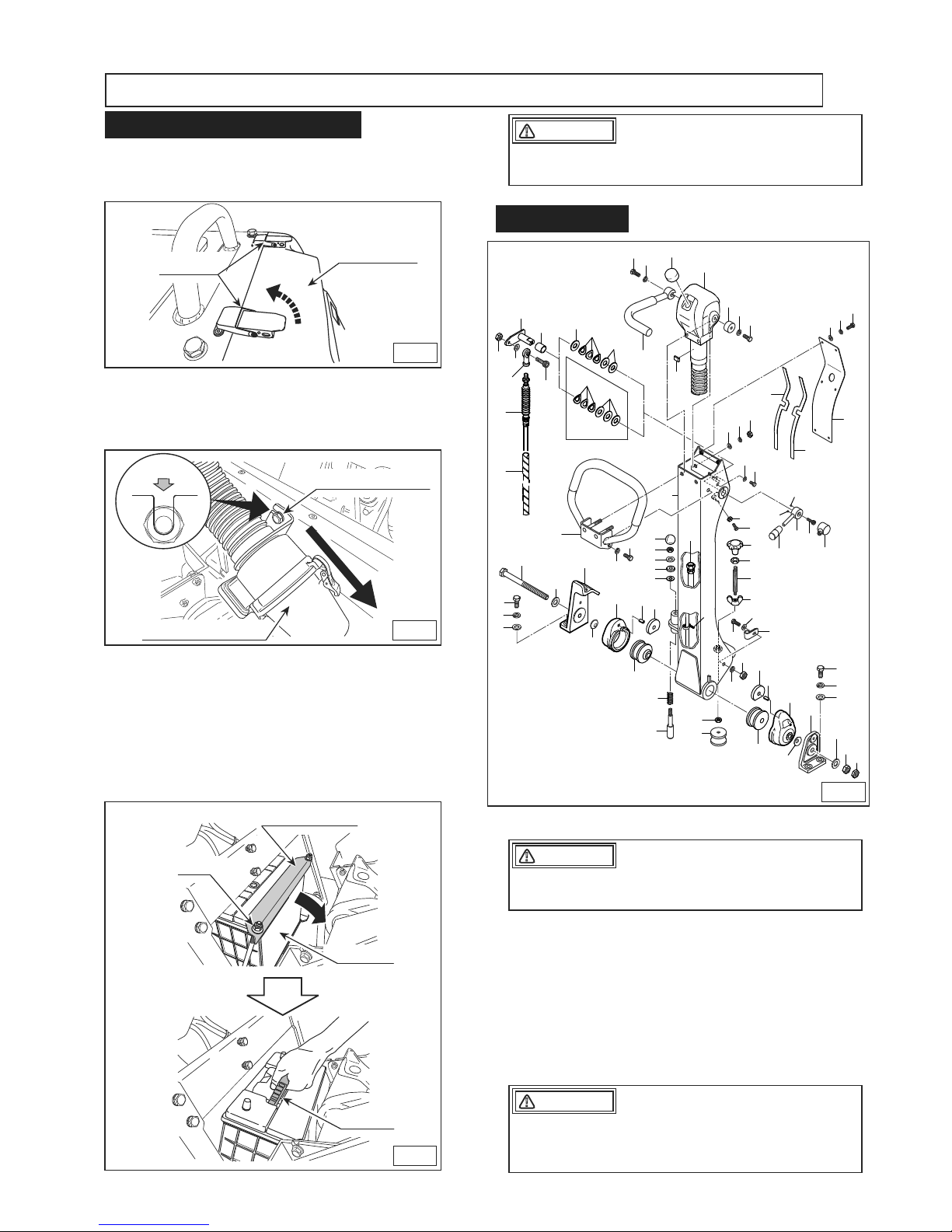
MVH-308
CONTROL
13
72
74-1
73-1
74-2
73-2
YANMAR:
L70V / L70N
93
92
Fig.4
Fig.3
Nut
Battery holder
Battery
Handle
Fig.1
Rear cover
Stopper
Fig.2
M8 bolts (2 bolts)
㻯㼁㼀
Cyclone cleaner
1.
2.
3.
4.
Remove the stopper at the two locations
on the top portion of the rear cover to
open the rear cover.(Fig.1)
Loosen, but not remove, the M8 bolts (2
bolts) used for cyclone cleaner attachment. Take out the cyclone cleaner downward.(Fig.2)
Take off the nuts and remove the battery
holder. After tilting the battery backward,
disconnect the battery terminal. When
doing so, always disconnect the black terminal on the minus side first.
By holding the top surface handle, pull
upward to remove the battery from the
machine.(Fig.3)
Pay sufficient attention so that the battery terminal will not touch the frame.
CAUTION
䟿
Start your work after the temperature of hydraulic oil gets sufficiently lowered.
CAUTION
䟿
After the hydraulic hose is removed, tighten
the caps on both ends to prevent entry of
dust.
CAUTION
䟿
8䠊DISASSEMBLY AND ASSEMBLY
8.1 How To Remove The Battery
8.2 Control Part
(1)
a.
b.
c.
d.
Disassembly
Remove 6 bolts (46), then remove the
handle cover (43).
Remove a bolt (57), then remove the
travel lever (55).
Remove 2 bolts (63) and 2 nuts (62), then
remove the handle grip (59).
Remove the hydraulic hose (51) from
hand pump (50), then remove the hand
pump (50) from the handle (16). (Fig. 4)
 Loading...