

Page 1

PLATE COMPACTOR
INSTRUCTION MANUAL
402-04808
MVC
MVC
-
40G
-
50GB
We thank you for selecting
Mikasa Plate Compactor. For
your safe and proper operation,
please read this manual and be
always sure to keep it ready for
reference.
Contentsof“DeclarationofConformity”
Pleasereferthe
ECDECLARATIONOFCONFORMITY
inthismanualaswell.
Original
Page 2

5) model
MVC-40G MVC-50GB
6) Equipment
item number
352062 352067
352068 352069
352070 352073
352050
7) Serial number
8) power source
cont. output
<m
ax.output
>
Robin EH09
1.5kW
<2.1kW>
Robin EX-13
2.2kW
<
3
.2kW>
9) Measured
sound power
level(dB)
97 101
10) Guaranteed
sound power
level(dB)
105 105
11) Max. Sound
pressure
level(dB)
84 91
For serial number, please refer it on front page.
Director, Product Control Division
Mikasa Sangyo Co., Ltd.
18) Place and date of the declaration
Keiichi YOSHIDA
Tokyo, Japan Feb, 2010
Signed by:
16) Other related Community Directives
2006/42/EC, 2005/88/EC, 2004/108/EC, 2002/88/EC(2004/26/EC)
EN500-1, EN500-4
e13*2000/14*2005/14*0472*01
4) Type: Vibratory Plates
Société Nationale de Certification et d’Homologation (SNCH)
11, route de Luxembourg
L-5230 Sandweiler LUXEMBOURG
15) Declaration
The equipment referred in this document, fulfills with all the
requirements of Directive 2000/14/EC
17) EC Conformity Certificate No:
1) DECLARATION OF CONFORMITY
14) Related Directive
Directive 2000/14/EC and, to be followed by Directive 2005/88/EC,
relating to the noise emission in the environment by equipment for
use outdoors.
2) Manufacturer’s name and address.
3) Name and address of the person who keeps the
technical documentation.
Mikasa Sangyo Co., Ltd.
4-3, Sarugaku-cho 1 chome, Chiyoda-ku, Tokyo101-0064, Japan
Yoshiharu Nishimaki, engineer
R. & D. Division, Mikasa Sangyo Co., Ltd.
Shiraoka-machi, Saitama, Japan
12) Conformity assessment according to Annex: VIII (Full Quality Assurance procedure)
13) Name and address of the Notified Body
Page 3

TABLE of CONTENTS
1. Preface
2. Applications, Warnings, Structure and Power Transmission
3. Warning Symbols
4. Safety Precautions
4.1 General precautions
4.2 Refueling precautions
4.3 Location and ventilation precautions
4.4 Precautions before starting
4.5 Precautions during work
4.6 Lifting precautions
4.7 Transportation and Storage precautions
4.8 Maintenance precautions
4.9 Labeling Position
4.10 Description of symbols used warning labels
5. Specifications
5.1 Machine specifications
5.2 Engine specifications
6. Appearance
6.1 Overall Dimensions
6.2 Control Unit Positions and Names
7. Inspection Before Operation
8. Operation
8.1 Starting
8.2 Operation
9. Stopping the machine
10. Transportation
10.1 Loading and Unloading
10.2 Transportation precautions
11. Storage
12. Regular Check and Adjustments
12.1 Inspection and maintenance schedule table
12.2 Changing the engine oil
12.3 Cleaning the air cleaner
12.4 Checking/Changing V-belt and Clutch
12.5 Inspection and Change of vibrator oil
13. Troubleshooting
1
1
2
2
7
8
10
11
13
13
13
14
16
2
2
3
3
3
3
3
4
5
6
7
7
8
9
11
12
13
13
14
15
15
15
15
Page 4

1
1. Preface
This operation manual describes the proper operation, basic inspection and maintenance procedures of the plate
compactor. Please read this operation manual before use in order to maximize the excellent performance of this
machine and make your work more efficient and effective.
After reading the manual, please keep it in a handy location for easy reference.
For the handling the engine, please refer to the separate engine operation manual.
For inquiries about repair parts, parts lists, service manuals, and repairs, please contact the store where you purchased
the product, our sales office, or the Mikasa Parts Service Center. For parts lists, please visit our homepage at:
http://www.mikasas.com/ where you can access Mikasa WEB parts lists.
●
●
●
●
The illustrations in this manual might slightly differ in part from the machine you actually
purchased due to design changes.
2. Applications, Warnings,
Structure and Power Transmission
Applications
Plate compactor is the machine that compacts the ground and it intends to make the surface smooth, by transmitting vibration through vibrating plate, which power generated from single rotor in vibrator case.
This machine is suitable for making the ground surface smooth, such as leveling the soil and beaching, finishing
the asphalt paving.
Warning about incorrect applications and techniques
This machine is hard to move forward on a soil with much water (especially clay soil). It is not suitable for such
application. This machine is difficult to level a ground include big stones due to insufficient compacting force. Plate
compactor is mainly applied for compacting surface smooth and it is not effective for jobs that requires heavy
compaction. In case of compacting ground deeply into lower layer, it is recommended to use Tamping Rammer,
Vibro Compactor or Vibration Roller of which compacting force is rather effective. Please use this compactor for
compacting surface on soil, sediment, beaching and asphalt. It is not recommended for use this machine for the
other applications.
Structure
The upper part is made up of Power source, Handle, Belt Cover, Water Tank for sprinkling and Guard Hook which
are fixed by Engine Base. The Engine base is fixed on Vibrating Plate by Shock Absorbing Rubber. The lower part
is made up of Vibrating Plate and Vibrator Unit that has an Eccentric rotary shaft built in. The power source is
transmitted from the centrifugal clutch on engine output shaft to the Eccentric rotary shaft through V-belt.
Power transmission
Air-cooled Single Cylinder Engine is amounted as power source and Centrifugal Clutch is fixed on engine output
shaft.
Centrifugal Clutch engages by running up the engine and engine R.P.M. is reduced to suitable number for
compacting. The rotation of engine is transmitted from V-pulley integrated with Clutch Drum to Vibrator Pulley
through V-belt.
Vibrator Pulley rotates Eccentric Rotor Shaft that is contained in Vibrator Case. The generated vibration created
from Eccentric Rotor is transmitted to Vibrating Plate.
Vibration of Vibrating Plate carries the machine forward; the vibration with the weight of the machine makes the
compaction of the ground possible.
Page 5
2
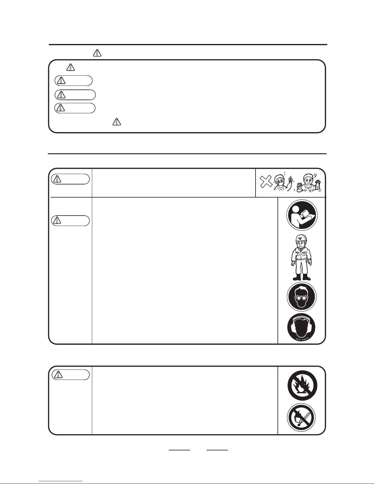
The triangle marks ( ) used in this manual and on the decals on the machine are warning symbols. Please follow these precautions.
Warning symbols indicating personnel hazards
Extremely hazardous. If the warning is not followed, it is likely to result in serious injury or death.
Hazardous. If the warning is not followed, it is likely to result in serious injury or death.
Potential hazard. If the warning is not followed, it may result in injury.
If the warning is not followed, it may result in property damage.
4.1 General precautions
4.2 Refueling precautions
!
Precautions (without mark)
!
!
3. Warning Symbols
4. Safety Precautions
○
○
○
Do not operate the machine,
Read this manual carefully and handle the machine as described to ensure safe
work.
For details about the engine, refer to the separate manual for the engine.
Make sure you understand the structure of the machine well.
For safe work, always wear protective gear (helmets, safety shoes, ear plugs,
etc.) and work in appropriate clothes.
Always check the machine before your work to make sure it is in normal
condition.
Decals on the machine (operation method labels, warning labels, etc.) are very
important for your safety. Keep the machine clean so that the decals can be read
all the time. Replace a decal if it becomes illegible.
Before performing maintenance work, be sure to turn the engine off.
It is very dangerous if children come into close contact with the machine. Have
the utmost concern about how and where to store the machine. In particular, for
an engine with a cell, always remove the starter key and keep it in a designated
place.
Before inspection and maintenance work, stop the engine, and do your work on
a flat surface area. If a cell is attached, remove the battery wiring before your
work.
Mikasa does not accept any responsibility for accidents caused by remodeling or
rework done on the machine.
When adding fuel,
Do not fill to the rim due to potential spillage.
After adding the fuel, tightly close the tank cap.
○ Make sure you work in a well ventilated location.
○ Make sure the engine is stopped and wait until it cools down.
○ Take the machine to a clear flat location without any combustibles nearby.
Be careful not to spill the fuel. Wipe well if any spill occurs.
●
●
●
●
●
●
●
●
●
●
●
●
●
●
DANGER
!
WARNING
!
CAUTION
!
WARNING
!
CAUTION
!
If you do not feel well due to overwork or illness.
If you are taking any medicine.
If you are under the influence of alcohol.
DANGER
!
Page 6
3
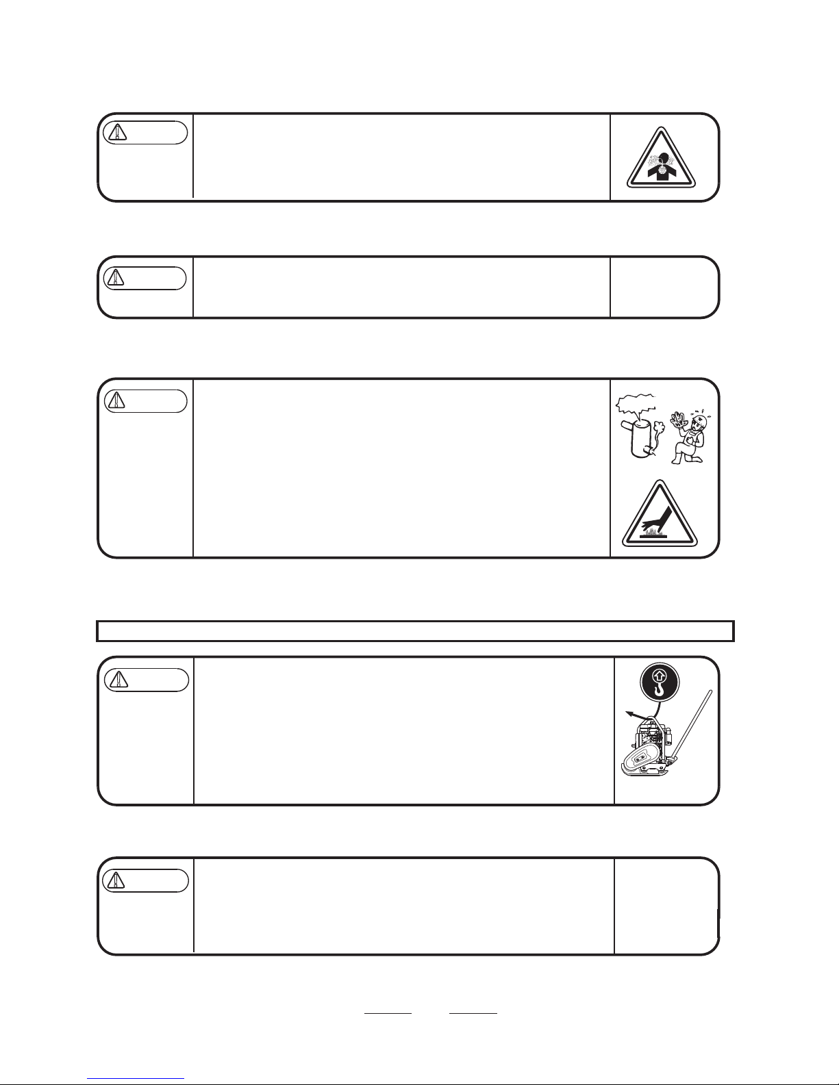
4.3 Location and Ventilation precautions
4.4 Precautions before starting
4.5 Precautions during work
4.6 Lifting precautions
For unloading using a crane, a licensed crane operator is needed. An operator should be qualified for crane and hooking work.
4.7 Transportation and Storage precautions
Do not run the machine in an unventilated location, such as indoors or inside a
tunnel. The exhaust gas from the engine contains toxic gases such as carbon
monoxide and is very hazardous.
Do not operate the machine near open flames.
Check each part to see if it is tightened properly. Vibration causes loosening of
bolts, which results in unexpected serious malfunctions of the machine. Tighten
the bolts securely.
Before starting the machine, make sure it is safe to start by checking your
surroundings for people and objects.
Always pay attention to your footing. Work in an area where you can maintain a
good balance of the machine and a safe comfortable posture.
The engine and muffler become very hot. Do not touch immediately after the
machine stops because they are still very hot.
If you notice deterioration of machine operation during your work, stop your work
immediately.
Before moving away from the machine, be sure to turn the engine off. Also when
the machine is transported, stop the engine and close the fuel cock.
Before lifting, check the machine parts (especially the hook and anti-vibration
rubber) for any damage and loosened or missing bolts.
Stop the engine and shut the fuel cock while lifting.
Use a wire rope with sufficient strength.
For lifting, use only one point hoisting hook, and do not lift at any other part.
When the machine is hoisted, never let people or animals come underneath.
For safety reasons, do not lift to a height that is higher than necessary.
Stop the engine during transportation.
Transport after the engine and the machine are cooled down.
Always drain the fuel before transporting.
Securely fix the machine to prevent it from moving or falling during
transportation.
●
●
●
●
●
●
●
●
●
●
●
●
●
●
●
●
●
●
DANGER
!
WARNING
!
CAUTION
!
CAUTION
!
Muffler
Burn warning
DANGER
!
Page 7
4
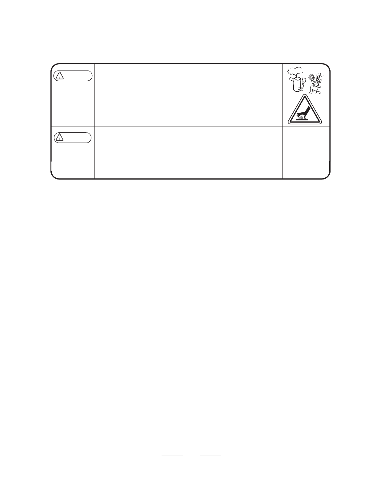
4.8 Maintenance precautions
Appropriate maintenance is required to ensure safe and efficient operation of the
machine. Always pay attention to the machine’s condition and keep it in good
condition. Pay special attention to the parts used for lifting, if they are not
maintained properly, it might result in a serious accident.
Start maintenance work after the machine has cooled down completely. The
muffler, in particular, becomes very hot, and there is a danger of burn. The
engine, engine oil and vibrator also become very hot. Be careful not to get
burned.
Always stop the engine before inspection and adjustment. If you are caught in a
rotating part, serious injury might occur.
After maintenance work, check the security parts to see if they are securely
installed. Special attention should be paid when checking bolts and nuts.
If disassembly is involved in maintenance, refer to the maintenance instruction
manual to make your work safe.
●
●
●
●
●
CAUTION
!
WARNING
!
Muffler
Burn warning
Page 8

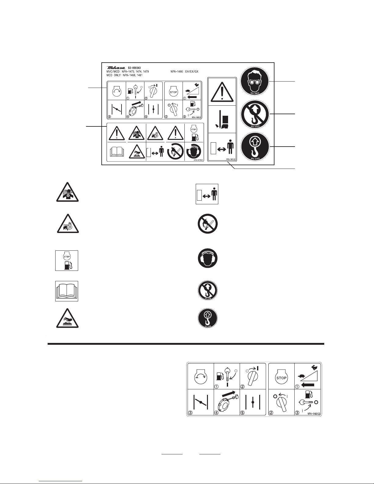
4.9 Labeling Position
5
MVC-50GB
1
9
10
7
7
2
5
5
8
6
6
3
4
4
MVC-40G
3
2
1
ENGINE BASE
RIGHT SIDE
ENGINE BASE
RIGHT SIDE
9202-10330
9209-00090
9209-00090
9209-00090
9209-00090
9202-00870
9201-09530
9201-00920
9201-05070
REF
No.
LABEL
No.
PART No. PART NAME Q’ TY REMARK
PLATE, SERIAL NO. / EU
DECAL,EC NOISE REQ.LWA105
DECAL,DO NOT LIFTING
DEAL,LIFTING POSITION
DEAL,CAUTION ICONS
DECAL,ENGINE HANDLING /GS
DECAL, WITHOUT ENGINE OIL
DECAL,MIKASA(125MM)YELLOW
DECAL, MIKASAMARK
DECAL,MIKASA MARK 125MM
Warnig labels
Starting, and stopping
40G
50GB/ WATER TANK
50GB/ WATER TANK
NPA-1033
NPA-1473
NPA-1474
NPA-1479
NPA-1480
NPA-87
NP-953
NP-92
NP-507
1
1
1
1
1
1
1
1
1
1
1
2
3
4
5
6
7
8
9
10
Page 9
6
4-10. Descriptions of symbols used on warning labels
START
①Open Fuel Cock to start
②Turn Stop Switch to “I”(ON) position
③Close Choke Lever
④Pull Recoil Starter to start
⑤Return Choke Lever to open
STOP
①Return Throttle Lever fully until “O”(OFF) position to stop work
②After cooling down enough, stop the engine to move Stop Switch to “O”(OFF) position
③Close Fuel Cock at the end
Starting, and stopping
P/N 9209-00090
DECAL, SET /MVC, MCD /EXP, EU
①
Danger: poisonous exhaust gas
Carbon monoxide poisoning may occur if
the exhaust gas is inhaled. Do not operate
the machine in a poorly ventilated area.
⑤
Be careful not to get burned.
Accidental burn may occur if you touch the
hot parts (engine, muffler, etc.) during operation or immediately after the machine stops.
Fire hazard
Stop the engine when refueling. Fire may
occur if a flame is near the tank fuel port.
⑦②
Be careful not to get caught in the
rotating parts.
During operation, be careful not to have your
fingers, body, clothes, etc. come in contact with
the rotating parts such as the V-belt and clutch.
P/N 9209-00090
DECAL, SET /MVC, MCD /EXP,EU
NPA-1479
NPA-1480
Do not use.
(For cutters)
Do not use.
(For cutters)
NPA-1473
NPA-1474
Lifting position.
For lifting, use only one point hoisting hook,
and do not lift at any other part.
⑩
⑥
Be careful not to approach danger
source.
During operation, Be careful not to approach hot
parts and rotating parts.
Lifting by the handle is prohibited.
Due to a falling risk, do not lift the
machine by the handle.
⑨
③
Refueling Hazard.
Don't fill the fuel tank while the engine is
running or hot.
Danger of hearing damage caused
by noise
Always use ear plugs while operating the
machine.
⑧
④
Read the manual carefully.
Always read the operation manual and have good
understanding of operation before your work.
① ②
④
③
⑤ ⑥
⑦
⑩
⑨
⑧
Page 10

7
5.Specifications
(The specifications may be changed without notice)
5.1 Machine specifications
5.2 Engine specifications
Manufacturer
Model
Max. Output
Fuel Tank Capacity
liters
Lubricant capacity
cc
Starting system
Set R.P.M rpm
Robin
EX13 (petrol)
3.2kW(4.3PS)
/4000min
-1
2.7
600
Recoil starting
3600
Robin
EH09-2F (petrol)
2.1kW(2.8PS)
/4200min
1.5
300
Recoil starting
4000
-1
MVC-40G
Folding Handle
MVC-50GB
Robin
EH09-2F
Overall Length
mm
855
Overall Width mm
290
Overall Height
mm
920
Plate Size (W X L) mm
290 x 420
Operating Weight
kg
46
47
Travelling Speed
m/min
25
Vibrating Frequency
Hz [ vpm ]
103 [ 6200 ]
Centrifugal Force
kN [ kgf ]
7.2 [ 730 ]
Vibrating unit
SAE 10W-30
Lubrication oil in
vibration case
cc
300
V-Belt Size
RPF3270
Model
Engine model
Robin
EX13
865
345
920
345 x 460
59
25
97 [ 5800 ]
9.8 [ 1000 ]
SAE 10W-30
300
RPF3270
STD
With Water Tank
STD
←
←
←
←
←
←
←
←
←
←
←
←
←
←
←
←
←
←
←
66
Water tank capacity
8.5L
cc
MVC-50GB
Robin
EX13
880
345
850
345 x 460
60
25
97 [ 5800 ]
9.8 [ 1000 ]
SAE 10W-30
300
RPF3270
With Water Tank
STD
←
←
←
←
←
←
←
←
←
←
67
Overall Length
mm
Overall Width mm
Overall Height
mm
Plate Size (W X L) mm
Operating Weight
kg
Travelling Speed
m/min
Vibrating Frequency
Hz [ vpm ]
Centrifugal Force
kN [ kgf ]
Vibrating unit
Lubrication oil in
vibration case
V-Belt Size
Model
Engine model
Water tank capacity
8.5L
cc
(Folding Handle )
940
925
865
865
Page 11

6.1 Overall Dimensions
8
.
6. Appearance
Dimensions may change without notice.
6.1.1 MVC-40G
6.1.2 MVC-50GB
290
590
855 ( Folding Handle: 865)
420
920 ( Folding Handle: 865 )
545
460
345
60
865 ( Folding Handle: 880)
920 ( Folding Handle: 850 )
Page 12

MVC-50GB
MVC-40G
4
3
1
5
2
6
7
8
9
6.2 Control Unit Positions and Names
1. Starter Grip
2. Engine ON/OFF Switch
3. Choke Lever
4. Speed Control Lever
5. Fuel Cock
6. Handle Bar
7. Folding Handle
8. Lifting Hook
9. Vibrating Plate
10. Vibration Case
11. Water Shut-Off Valve
9
9
7
2
8
10
11
4
1
3
5
Page 13

10
7. Inspection Before Operation
Clean each part of the machine well to maintain dirt and
dust-free condition. Pay special attention to the soil
adhered to the bottom of the vibrating plate, engine
cooling air inlet, and the carburetor and air cleaner area
to keep those parts clean.
Check each part for any looseness of bolts. Vibration
causes bolts & nuts to loosen, which might result in
unexpected accident or malfunction.
Inspect the guard hook, belt cover and anti-vibration
rubber, as well as to check the function of speed adjustment wire and speed adjusting lever.
Check V-belt tension. The belt should have about 10 –
15mm of flexibility when pushed strongly with a finger
at the mid-point between the axes. If V-belt is loosened,
power is not transmitted connectively, which reduces
compacting force and shortens the life of V-belt. In
addition, the generated compaction force will lead to
irregular vibrations when the engine revolutions are
increased, and may result in a machine failure.
Set the engine on a level surface to check the oil level.
If the oil level is low, add oil. Use the following engine
oil.
Quality: Gasoline engine oil, Grade SE or above
Viscosity: SAE No. 30 at 20°C and above (summer)
SAE10W-30
1
2
3
4
5
Upper level
Lower level
(Refill line)
Oil Gauge
Fig.1
DANGER
!
Conduct inspection while the engine is stopped.
If you get caught in the rotating parts, you may
suffer serious damage. Conduct inspection after
making this machine level and checking that the
body does not move.
Refer to "Regular Check and Adjustments" on
page 14 for the inspection points before starting
operation.
★
Temperature
Morethan25℃
10〜25℃
10〜0℃
Lessthan0℃
Useoil
SAE#30
SAE#30,#20
SAE#20
SAE#10
Page 14

11
Set the machine on a level surface, then remove the oil
gauge of the vibrator. Check the oil gauge to see if the
oil is at the specified level. Use engine oil SAE10W-30
as lubrication oil.
Recommended oil quantity for MVC-40G/50G is 300cc.
Remove the oil plug in Vibrator Assembly and check
the oil level. Make sure the oil quantity is set at level of
plug hole for checking. Every month or every 200 hours
of operation, replace the oil.
A regular grade gasoline should be used in the engine.
When filling the fuel tank, make sure the fuel filter is
used.
Never refuel this machine while leaving the engine
running. There is danger of fire.
Never smoke, or put other flames close to this
machine while refueling. Serious hazards such as
burns and fire may result.
Choose a place free from flammable substances
for refueling. Be careful not to spill fuel. In case fuel
should be spilled, wipe off the spilled fuel
completely.
6
7
DANGER
!
DANGER
!
DANGER
!
DANGER
FUEL
Fire risk
Fig. 2
Gasoline engine
8.1 Starting
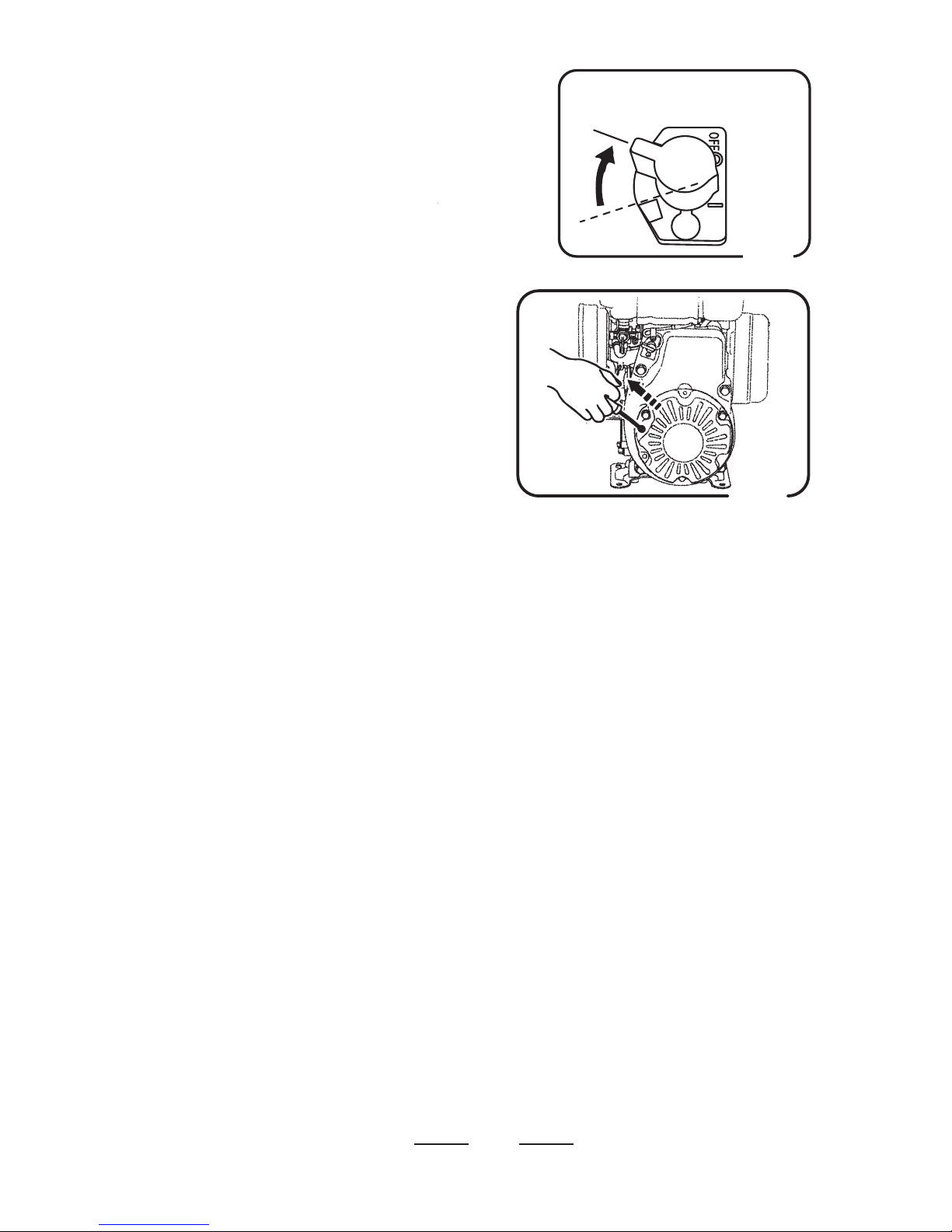
8.Operation
Turn the lever of the fuel cock downward and feed
fuel. (Figs.3-1 , 3-2)
1
DANGER
!
The engine exhaust gas contains carbon dioxide
and is very dangerous.
Do not use this machine where ventilation is poor.
MVC-40G
( ROBIN EH09-2F )
Choke Lever
High Speed
Fig.3-1
Open
Fuel Cock
Close
Speed control lever
MVC-50GB
(ROBIN EX13)
High Speed
Speed control lever
Choke Lever
Fuel Cock
Open
Close
Fig.3-2
Page 15
12
Turn the stop switch to “ON (I)” position. (Fig.4)
Open the speed control lever half. (Fig.3-1, 3-2)
When it is cold or the engine does not start easily,
close the choke lever. (Figs. 3-1 , 3-2)
2
3
Engine Switch
ON
“ON”
(RUN)
Fig.4
Grip the starting knob of the recoil starter. When you
pull the rope a little, you will feel some resistance.
Then pull it at a stroke. Be careful not to pull the rope
too strongly, or the rope may break or come off.
(Fig.5)
When the engine has started, return the speed control
lever to the low speed position immediately. Listening
to the sound of the explosion, return the choke lever
gradually to the fully open condition. (Fig.3-1 , 3-2)
After the start, be sure to conduct the warm-up
operation at low speed for 2-5 minutes. This is
particularly important when it is cold. During this time,
check for any abnormalities such as gas leakage.
Note: If you leave the speed control lever
half-open, the centrifugal clutch turns into a
slipped state. This may cause a failure of the
centrifugal clutch, and also cause abnormal
vibration of this machine, which is very
dangerous. So, as soon as the engine has
started, return the speed control lever to the
low-speed position.
4
5
Fig.5
8.2 Operation
If you open the speed control lever at a stroke, this
machine starts vibration and moves forward. If you
open it slowly, the clutch may slip, so open the speed
control lever at a stroke without hesitation. (Figs. 3-1 ,
3-2)
When this machine is used on cohesive soils, the
vibrating plate does not move over the ground easily
and the travel speed becomes slow. Check that clay is
not adhering to the bottom of the cvibration plate. The
compaction force of this machine does not act
effectively on cohesive soils or soils of a high moisture
ratio. In this case, use other machine such as a
rammer, or dry the soils and decrease the moisture
ratio.
When you stop the operation, return the speed control
lever at a stroke.
1
2
3
Page 16
13
11 Storage
Conduct fueling and replenishment/change of oil
without omission. Remove the spark plug, put a few
drops of engine oil into the cylinder, and rotate the
engine manually for spreading the oil inside sufficiently.
Securely cover the air cleaner and muffler air inlets and
exhaust port.
Do not leave the machine outdoors. Keep it indoors.
Don not store this machine by laying it on its side (or
backward).
4
5
6
7
CAUTION
!
9. Stopping the machine
When you finish the work and stop the engine, return
the speed control lever to the low speed position, and
keep the engine running at low speed for 3-5minutes.
When the temperature of the engine has decreased,
stop the engine.
If you stop the engine while it is still hot, this
machine will be affected adversely, causing, for
example, burning of the oil film on the inner wall
of the cylinder, which may accelerate wear of the
inner wall of the cylinder. This may result in a
shorter life of this machine, or cause unexpected
failure.
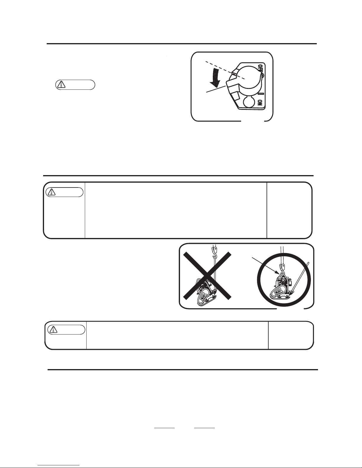
Turn the engine switch to the OFF position, then the
engine stops. (Fig. 6)
Close the lever of the fuel cock. (Fig. 3-1, 3-2)
1
2
Fig. 6
ON
“OFF”
(Stop)
Engine switch
Wash with water to remove any dust and dirt from all
parts of the machine.
Store in a dry area away from direct sunlight after
putting the cover over the machine to prevent dust and
dirt buildup.
1
2
(When storing this machine for an extended period of time)
Drain the fuel from the fuel tank, fuel pipe, and
carburetor completely.
3
10.1 Loading and Unloading
10.2 Transportation precautions
For loading and unloading using a crane, an
operator qualified for cranes and hooking works is
needed.
Use a crane for loading and unloading the machine.
Designate a person to guide the loading and unloading,
and always work under the instruction of that person.
When lifting, always use a special hook on the guard
frame. (Fig. 7)
Never lift by hooking the handle.
1
2
3
10 Transportation
Make sure there is no breakage of guard frame and anti-vibration rubber
nor loosened or missing bolts.
Always stop the engine when lifting.
Use an intact wire rope without any deformation with sufficient strength.
Slowly lift upward without applying any impact. Never let people or animals
go under the lifted machine.
For safety reasons, do not lift to a height that is higher than necessary.
●
●
●
●
●
WARNING
!
WARNING
!
Stop the engine when the machine is transported.
Always drain the fuel before transportation.
Fix the machine securely to prevent the machine from moving or falling.
●
●
●
Special hook
on the guard frame
Fig.7
Page 17

14
12.1 Inspection and maintenance schedule table
For details about the check and maintenance of the engine, please refer to the attached engine operation manual.
Caution:
The above table shows the check frequency for standard condition.
The check frequency may vary depending on the condition in which the machine is used.
For check of bolt and nut looseness and tightening, please see the following tightening torque list.
Tightening torque list (unit: kgf-cm, 1kgf-cm=9.80665N-cm)
6mm
8mm 10mm
12mm 14mm
16mm 18mm 20mm
4T(SS41)
70
150
300
500 750
1,100
1,400
2,000
6-8T(S45C)
100
250
500
800 1,300
2,000
2,700
3,800
11T(SCM3)
150
400
800
1,200
2,000
2,900 4,200
5,600
When the mating material is aluminum.
100
300~350 650~700
Thread diameter
Material
(Bolts used on the machine are all right-hand thread.)
12. Regular Check and Adjustments
Check frequency Check parts Check items Oils
Appearance
Flaw, deformation
Fuel tank
Leakage
Fuel system
Leakage
Engine oil
Leakage, oil level, dirt
Engine oil
Shock absorber Crack, damage, wear
Vibrator oil
Leakage
Engine oil
Air cleaner
Dust on sponge
Guard frame
Breakage, flaw, loosened
or missing bolts and nuts
Back and forth motion
lever operation
Operation check, play
Bolts and nuts
Looseness, missing
Engine oil
Replac
e only after
the first 20 hours
Every 2 years
Fuel pipes
Change
Air cleaner element ChangeIrregular
Daily
(before starting)
Every 20 hours
Engine oil
Change
Engine oil
Engine oil filter
Washing
Vibrator oil
Leakage, oil level, dirt
Engine oil
V-belt for vibrator Flaw, tension
Clutch
Dirt, flaw, wear
Vibrator oil
Change
Engine oil
Fuel filter
Change
Every 300 hours
Every 100 hours
Every 200 hours
Engine oil
Page 18

15
Fig.8
Changing the engine oil
Perform the first engine oil change after 20 hours of
operation, then change at every 100 hours.
Cleaning the air cleaner
When the air cleaner element becomes dirty, the
engine does not start smoothly, and sufficient output
can not be obtained. Machine operation will be
affected and the engine life will be shortened greatly.
Do not forget to clean the element. (For details, please
see the separate engine operation manual.) If the
element can not be cleaned, replace it with a new one.
Checking/Changing V-belt and Clutch
Checking V-belt
Remove the belt cover and check that V-belt is
properly stretched every 200 hours. Press on the
portion midway between the two shafts with your
fingers strongly. The belt is properly stretched if that
portion bows by about 10-15 mm.
Checking the clutch
Inspect the clutch concurrently with the inspection of
V-belt. Check visually for burning of each clutch-shoe.
Check for wear the lining shoe or the like in the
operation check. If the shoe wears, power
transmission is not performed properly and the clutch
slips. Check wear of and damage to the V-groove. If
the V-groove is stained, clean it thoroughly.
When the vibration weakens during operation, or this
machine does not vibrate at all though the engine
rotates normally, conduct the inspection or change of
the V-belt and clutch without regard to the regular
inspection of every 200 hours.
Inspection and Change of vibrator oil
Make this machine level, and remove the oil level plug
off the vibrator. Check that vibrator oil is provided up
to the mouth level. The oil level plug is on the right
side of the vibrator case (opposite to the belt side).
(Refer to Fig.1 on page 10.)
Use the engine oil #10W-30 for vibrator oil. Refer to
page 7 for the amount. Drain the vibrator oil
completely by removing the plug and tilting the body
once a month or every 200 hours’ operation. Replace
with new oil.
12.2
12.3
12.4
1
2
12.5
CAUTION
!
Always stop the engine before inspection and
adjustment. If you are caught in a rotating part,
serious injury might occur.
CAUTION
!
Page 19

1. Gasoline engine
(1) Starting problem
Fuel is supplied, but
Spark Plug does
not ignite
Electricity reaches
to High Voltage Cable
Electricity does not
reach to High Voltage
Cable
Bridging Spark Plug
Carbon accumulated on Spark Plug
Short circuit due to insulation problems of
Spark Plug
Inappropriate gap of Spark Plug
Short circuit of Stop Switch
Ignition coil problems
Oil Sensor problem
Th
e wrong fuel is used
Mixing of water or dust contamination
Air Cleaner not working
Intake/Exhaust Valve is stuck or pushed up
Piston Ring, Cylinder wear enough
Cylinder head, Spark Plug tightening problem
Head gasket or Spark Plug Gasket breaks
Compression is
good
No fuel in tank
Fuel Cock does not open properly
Clogging of Fuel Filter
Clogging of Tank Cap Air Hole
Air trapped in fuel pipe
Fuel supplied, and
Spark Plug
ignites
Fuel does not reach
to Carburetor
(2) Operation problem
Compression is
good and no firing
problem
Insufficient compression (see the item “compression is not good.” )
Compression is
good, but no firing
Water mixed in fuel
Dirt of Spark Plug
Ignition Coil problem
Lowered power
Engine overheating
Carbon accumulated inside combustion chamber and exhaust hole.
Thermal value of Spark Plug is poor
Dirt and breakage of Cooling Fin
Revolution fluctuation
Governor adjustment inappropriate
Governor Spring problem
Fuel flows in proper
Air taken from Intake Pipe line
Clogging of Pilot Jet ( Idle speed fluctuates improper)
(3) Recoil Starter does not work well
Clogging of dust from rotating part
Weakening of Spiral Spring
16
13. Troubleshooting
nsufficient engine output and inappropriate high speed set revolution
Slipping of Clutch
Slipping of V-belt
Too much vibrator oil
Failure inside Vibrator Unit
Wear / damage of Shock Absorber
2. Main body
Low travel speed and
vibration weak
D
irt of Air Cleaner
Carbon accumulated in Cylinder.
Fuel Level in Carburetor inproper
Compression is
not good
Page 20

(402-04801)08-07-00(BSC)
 Loading...