

Page 1

TAMPINGRAMMER
MT-76D
MT-76DL
INSTRUCTIONMANUAL
en
http://www.mikasas.com
WethankyouforselectingMikasaTampingRammer.
Foryoursafeandproperoperation,pleasereadthismanualand
bealwayssuretokeepitreadyforreference.
Contentsof“DeclarationofConformity”
PleaserefertheECDECLARATIONOFCONFORMITY
inthismanualaswell.
302-00912
*302-00912*
Page 2

Page 3

1) DECLARATION OF CO NF O RMITY
2) Manufacturer’s name and address.
3) Name and address of the person who keeps the
technical documentation.
4) Type: Vibratory Rammers
5) model
6) Equipment
item number
7) Serial number
8) power source
cont. output
<max.output>
9) Measured
sound power
level(dB)
10) Guaranteed
sound power
level(dB)
11) Operator's
sound pressure
level(dB)
MT-76D MT-76DL CE
251555, 251556,
251557, 251558,
251559, 251560
Yanmer L48N
3.1kW
<3.5kW>
251561
Yanmer L48N
3.1kW
<3.5kW>
107 105
108 107
96 97
For serial number, please refer it on front page.
12) Conformity assessment according to A nnex:
Mikas a Sangyo Co., Lt d.
4-3, Sarugaku-cho 1 chome, Chiyoda-ku, Tokyo101-0064, Japan
Takahiro Kis hino, engineer
R. & D. Division, Mikasa Sangyo Co., Ltd.
Shiraoka-city, Saitama, Japan
VIII (Full Quality Assurance procedure)
13) Name and address of the Notifi ed Body
14) Related Directive
15) Declaration
16) Other related Community Directives
17) EC Conformity Certificate No:
18) Place and date of the declaration
Société Nationale de Certification et d’ Homologation (S NCH)
11, route de Luxembourg
L-5230 Sandweiler LUXEMBOURG
Directive 2000/14/EC and, to be followed by Directive 2005/88/EC,
relating to the noise emission in the environment by equipment for
use outdoors.
The equipment referred in this document, fulfills with all the
requirements of Directive 2000/14/EC
2006/42/EC, 2005/ 88/ E C, 2004/108/EC, 2002/88/ E C(2004/ 26/EC)
EN500-1, EN500-4
e13*2000/14*2005/14*0472*01
Tokyo, Japan May, 2016
Signed by:
Keiichi YOSHIDA
Director, P roduct Control Division
Mikas a Sangyo Co., Lt d.
Page 4

Italian
Garanzia di Qualità totale )
1. DICHIARAZIONE “CE” DI CONFORMITÁ
2. Nome e indirizzo Fabbricante
3. Nome e indirizzo della persona che conserva la
documentazione tecnica
4. Tipo: Piastre vibranti
5. Modello
6. Codice macchina
7. Numeridi matricola
8. Potenza installata netta <resa massima>
9. Livello di potenza sonora misurato (dB)
10. Livello di potenza sonora garantito
11. Livello massimo di pressione sonora
12. Valutazione di conformità in accordo all'annesso VIII
( procedura Garanzia di Qualità totale
13. Nome dell'organismo notificato
14. Rappresentante Autorizzato in Europa
15. Direttiva di riferimento
13. Nom et adresse de l'organisme notifié
14. Mandataire dans la Communaute Europeenne
15. Directive concernee
Est egalement conforme aux dispositions de la directive
<<emission sonores des equipements utilises a l'exterieur
des batiments>> 2000/14/CE et aux legislations nationales
la transposant.
16. Declaration
L'équipement de référence satisfait aux exigences de la
Directive 2000/14/EC
17. Autres directives communautaires concernees
18. Certificate deConformite CE numero:
19. Lieu et date de la declaratio
Spanish
1. DECLARACIÓN “CE” DE CONFORMIDAD
2. Nombre y dirección del fabricante
Direttiva 2000/14/CE su l'emissione acustica ambientale
delle macchine ed attrezzature destinate a funzionare
all'aperto
16. Dichiarazione
Le attrezzature riportate nel documento soddisfano i requisiti
della Direttiva 2000/14/CE
17. Altre Direttive Comunitarie di riferimento
18. Certificato di Conformità CE No:
19. Luogo e data della dichiarazione
French
1. DECLARATION « CE » DE CONFORMITE
2. Non et adresse du Fabricant
3. Nom et adresse de la personne qui défient les documents
techniques
4. Type du materiel: Plaques vibrantes
5. Modello
3. Nombre y dirección de la persona que guarda la
documentación técnica.
4. Tipo: Bandejas vibrantes
5. Modelo
6. Número de referencia del equipo
7. Numeros de serie
8. Potencia neta instlada <rendimineto maximo>
9. Nivel sonoro medido del motor ( dB )
10. Nivel sonoro garantizado del motor ( dB )
11. Máximo nivel sonoro de presión ( dB )
12. Evaluación de la Conformidad de acuerdo al Anexo VIII
( Prcedimiento de total garantía asegurada )
13. Nombre y dirección de la Entidad Notificada
14. Representante autorizado
15. Directiva relacionada
Directiva 2000/14/CE en relación a la emisión sonora en el
ambiente por equipos que trabajan en espacios abiertos
6. Numero equipement
7. Numéro de série
8. Puissance reseau <rendement maximal>
9. Niveau sonore mesure(dB)
10. Niveau sonore garanti(dB)
11. Niveau sonore maximum
12. Certification de conformite selon l'annexe VIII ( procedura
16. Declaración
El equipo referido en este documento , cumple con todos los
requerimientos de la Directiva 2000/14/EC
17. Otras Directivas Comunitarias relacionadas
18. Certificado de Conformidad CE Nº
19. Lugar y fecha de la declaración
Page 5

Preface
This instruction manual describes the proper methods for using the tamping rammer, as well as
simple checks and maintenance. Be sure to read this instruction manual before using the
rammer, in order to get full use of the excellent performance of this machine, to improve your
operation and to perform engineering work effectively.
After reading this manual, store it in a handy location for easy reference.
For details about the engine in this machine, see the separate instruction manual for the
engine.
For inquiries about repair parts, parts lists, service manuals, and repair of the machine, please
contact the shop where you purchased it, our sales office, or the Mikasa Parts Service Center.
In addition, parts lists are available on the MIKASA website at:
http://www.mikasas.com/english/
The illustrations and Figures in this manual may be different from the machine you
actually purchased due to design changes and other reasons for improvement.
Application
Though compact and lightweight, this rammer creates a strong impact and you may expect a
large tamping effect on the ground.
It will compact nearly all types of soil, except soft soil that contains too much moisture.
Use this rammer to tamp the ground for creating roads, embankments, and to prepare the
surface to support buildings. It can also be used when burying gas or water lines, and electric
cables.
Warning about incorrect applications and techniques
Do not use this machine on ground that is harder than the machine can handle, or for driving
pilings or tamping rock beds. Furthermore, use of the machine on sloping ground such as the
side of an embankment, may be make the machine unstable and can cause an accident. It can
also result in premature machine wear due to uneven loads on the machine.
Use the machine with confidence for tamping earth and sand, soil, sand, gravel, and asphalt.
Do not use the machine for other type of jobs.
Structure
The upper section of the machine functions as a weight and consists of an engine section
guide, a gear reducer section, and reciprocating section. It also accommodates the handle and
the fuel tank sections, which are connected by rubber dampers.
The lower section of the machine which hits the ground, consists of a spring case to engage
sliding motion, a sloping section to allow the machine to tilt toward the front, bellows to cover
the foot, a sliding section, and a protective sleeve.
Power transmission
Power is provided by an air-cooled, 4-cycle, single-cylinder diesel engine. The output end of the
engine crankshaft is equipped with a centrifugal clutch.
As the engine speed increases, the centrifugal clutch expands and a pinion gear that is a part
of the clutch drum engages a gear in the crank shaft on the main frame. The engine speed is
decreased in order to produce the required force for tamping.
The rotating motion of the main frame crankshaft is converted to a reciprocating motion through
a connecting rod. This reciprocating motion causes the foot to go up and down through a strong
coil spring. The weight of the main body and the strong force from the engine compress the
spring and the foot moves up and down, striking the ground forcefully.
1
Page 6
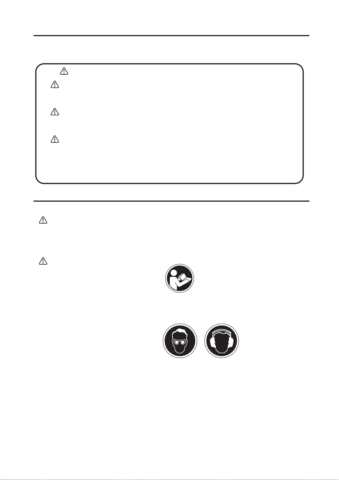
Warning labels
The triangle shaped marks used in this manual and on the decals stuck on the
main body indicate common hazards. Be sure to read and observe the cautions
described.
Warning labels indicating hazards to humans and to equipment.
!
!
DANGER:
Denotes an extreme hazard. It calls attention to a procedure,
practice, condition or the like, which, if not correctly performed
or adhered to, is likely to result in serious injury or death.
!
WARNING:
Denotes a hazard. It calls attention to a procedure, practice,
condition or the like, which, if not correctly performed or
adhered to, could result in serious injury or death.
!
CAUTION:
Denotes a hazard. It calls attention to a procedure, practice,
condition or the like, which, if not correctly performed or
adhered to, could result in injury to people and may damage or
destroy the product.
Precautions (without a triangular mark):
Failure to follow the instructions may
result in damage to property.
Precautions for safety
General precautions
!
WARNING
■
DO NOT work in the following conditions.
- If you do not feel well due to overwork or illness.
- If you are taking any medicine.
- If you are under the influence of alcohol.
!
CAUTION
■
Read this instruction manual carefully
and handle the machine as described
so that you can work safely.
■
For details about the engine, refer the separate instruction manual for the engine.
Make sure you thoroughly understand the construction and operation of the machine.
■
T o work s afe l y, always wear
protective clothing (helmet, safety
glasses, safety shoes, ear plugs etc.)
and appropriate work clothes.
Always check the machine to make
sure that it is normal before starting
operation.
■
The decals on the machine body (operating methods, warning decals, etc.) are very
important to ensure safety. Keep the machine body clean so that they can be read at all
times. If any decal cannot be read, replace it with a new one.
■
It is very dangerous if children come into contact with the machine. Take the utmost care
about how and where the machine is stored.
■
Before performing any maintenance, be sure to turn the engine off.
2
■
Mikasa does not accept any liability for accidents or problems caused as a result of not
using genuine Mikasa parts (foot assembly, etc.), or if the machine has been modified.
Page 7

Precautions when adding fuel
!
DANGER
■
When adding fuel.
-
Be sure to work in a well ventilated location.
-
Be sure to turn the engine off and wait until it has cooled down.
-
Take the machine to a clear flat location without any combustibles nearby. Be careful not
any fuel. If you do spill some fuel of diesel, wipe it all up.
-
Do not allow any open flames nearby
while adding fuel. (I n par
smoking while adding fuel is strictly
prohibited.)
■
Adding fuel until it comes too close to the top of the inlet may cause the fuel to overflow.
That is dangerous. Follow the instructions in the engine manual about the specified fuel
level.
■
When through adding fuel, tighten the tank cap securely.
tic ular,
Precautions about where to use the machine
!
DANGER
■
D O NO T run the engine in an
unventilated location, such as indoors
or in a tunnel. The exhaust gas from
the engine is carbon monoxide and is
deadly.
■
DO NOT operate the machine near
open fires.
Precautions before starting work
CAUTION
!
■
If you use the machine for a long time, be careful to watch for signs of vibration syndrome.
Since this machine vibrates, operation for a long time may have a negative effect on your
body. Take sufficient breaks while working.
■
Before starting to operate the machine, check for other people or obstacles that are too
close for safe operation.
■
When starting the engine, the rammer may jump suddenly. Hold the handle firmly with one
hand and pull the recoil starter with the other hand.
■
Always be careful around scaffolding. Operate the rammer in a stable manner so that it will
not become unbalanced.
■
During operation, don't let the foot of the machine come too close to your foot. The plate
may smash your foot.
■
The main part s of the engine, the
muffler, and muffler cover will be very
hot during operation. Be careful not to
touch them during operation or soon
after operation.
■
If you encounter any problems or abnormality with the machine during operation, while
moving it, or stopping operation, stop work immediately.
■
Before leaving the machine, be sure to turn the engine off. Also, make sure to turn the
engine off if you want to move the machine. When the throttle lever is in the stop position,
the fuel cock is closed. Do not move the lever away from the stop position.
■
When lifting the machine by the handle, be careful not to pinch your fingers between the
handle and main body.
3
Page 8

Precautions before starting work(Continued)
!
DANGER
■
Take the utmost care not to allow the
machine to fall during work, or when
s t opped or stored. Secure the
machine with a rope or similar tie
when stored or left i d l e so that it
cannot fall. If the rammer falls over
when children are around, a serious
accident may occur. If the machine
foot is worn, the mac hine will be
especially unstable. If the machine
foot is worn badly, replace it with a
new one.
■
If the machine falls over while working, the machine will move forward due to the kicking
motion of the foot while it is lying on its side. If the ground is solid, it will move quickly and is
very dangerous. To ensure that the operator and anyone nearby are safe, turn the throttle
lever to the engine stop position and make sure the machine stops. You must be extremely
careful when working on a road because a serious accident can easily occur.
Precautions while lifting
!
DANGER
■
Before lifting the machine, make sure that there is no damage to any of the components on
the machine (look especially for damage to the rubber dampers and the hook). There must
not be any loose or missing screws and the machine must generally be in a safe condition.
■
Turn the engine off before lifting the machine.
■
Use wire cables with enough strength to support the machine.
■
DO NOT lift it higher than necessary, for safety.
■
DO NOTuse a damaged wire cable.
■
Only use the single hook to lift the
machine. DO NOT support it from any
other points (such as the handle).
■
Never lift or lower the machine rapidly when using a hydraulic shovel or a crane.
■
When lifting the machine, do not allow any people or animals to pass under or near the
machine.
■
When using any type of equipment to lift the machine, be careful that the lifting equipment
does not cause an accident. Make sure you check the lifting equipment carefully, to ensure
that there are no problems or damage.
4
Page 9

Transportation and storage precautions
!
DANGER
When transporting
■
Before transporting the machine, stop the engine.
■
DO NOT try to move it before the engine and machine body have cooled down enough.
■
Drain any fuel before transporting the machine.
■
Transport the rammer in a manner that keeps it level. If you must lay the machine down to
transport it, drain any fuel from the fuel tank. Then close the fuel tank cap and oil fill plug
securely. Next, position the machine so that the muffler will be facing down.
■
Secure the machine body so that the machine cannot move or fall during transportation.
■
When you want to lift the machine by gripping the handle, be careful not to pinch your
fingers or hands between the handle and the main body.
■
Since this machine is quite heavy, use a truck specifically designed to transport heavy
objects.
When storing the machine
■
After the engine and machine body have cooled down enough, store the rammer so that it is
level. Fasten the machine as needed so that the machine cannot fall down. If it you must lay
the machine down, close the fuel tank cap and oil fill plug securely. Arrange the machine
position so that the muffler will be facing down. After it is lying down, make sure there are
no oil or fuel leaks. (If fuel is leaking, drain it all from the fuel tank.)
Maintenance precautions
!
WARNING
■
Appropriate maintenance of the machine is required to ensure safety and keep the machine
performing well. Always be aware of the machine's condition and keep it in good condition.
!
CAUTION
■
Be sure to turn the engine off before
checking or adjusting the machine.
■
T he muffler and muffler guard
become very hot. Do not touch them
until they will have cooled down.
■
The lubrication oil and engine oil are
very hot and can burn you. Do not
start any maintenance on the
machine while the oil remains hot.
■
After performing any maintenance, check the condition of the safety components and the
general safety of the machine. In particular, check the nuts and bolts thoroughly.
■
If you have to disassemble any components on the machine, be sure to ref er t he
maintenance standard sheets and always work safely.
5
Page 10

Specifications
Model MT-76D/76DL
Overall height
Overall width 410 mm
Overall length
Impact shoe width 285 mm
Jumping stroke
Impact number
Impact force (max.)
Clutch Automatic centrifugal clutch
Total weight 82 kg
10.8~11.7Hz
1,010 mm
740 mm
50~80 mm
(650~700blows/min.)
15.7kN (1,600kgf)
Specifications for engine
Model Yanmar L48N6-SMK
Type Air-cooled 4-stroke diesel engine
Piston displacement 219cc
Max.Output
Cooling system
Lubricant
Fuel
Starting system Recoil starter with Auto-return decompression device
3.5 kw (4.7 PS) / 3600 rpm
Air-cooled by fan
Diesel engine lubricating oil
API classification "CC" or "CD" grade
Automotive Diesel Fuel
Hand-Arm Vibration Level
Model
MT-76D
MT-76DL
Vibration Level is in comply with EU Directive2002/44/EC and the value is shown as 3 axix
min. vibration level.
Test course ( Crushed gravel ) is in comply with EN500-4.
The above values are subject to change in case that the machine is modified or/and the
required regulations change.
Specifications are general and subject to change without notice.
※
If exact measurements are required, equipment should be weighed and measured.
! !
Ahv
(m/sec
18.5
16.8
WARNING:
2
)
The engine exhaust from this product con-
6
tains chemicals known to the State of California to cause cancer,birth defects or other reproductive harm.
Page 11

Fuel tank
Air Cleaner
Handle
Bellows
Protect sleeve
Foot
1.Definition of Tamping Rammer
The Mikasa MT-76D diesel rammer is a powerful
compacting tool capable of applying tremendous
force in consecutive impacts to a soil surface.
The impact force of the MT-76D levels and
uniformly compacts voids between soil particles to
increase dry density. Its applications include soil
compacting for road, embankment and reservoirs as
well as backfilling for gas pipelines, water pipelines
and cable installation work.
2. Construction of Tamping Rammer
The rammer is equipped with an air-cooled,
four-stroke diesel engine. Transmission of the
power takes place by increasing engine speed to
engage a centrifugal clutch.
Circular motion is converted into vertical motion to
create impact force.
3. Prior to Operation
3-1 Identification of Controls:
1. Throttle
2. Engine Lubrication Oil
3. Oil Fill Plug
4. Oil Level Sight Glass
5. Recoil Starter Handle
Throttle lever
Fuel filter
Recoil stater
Oil level gauge (engine)
Oil filter (engine)
Oil level sight glass
Drain plug
Preoperation Inspection:
3-2
Rammer Gearbox and Spring Cylinder This unit
uses an oil bath lubrication system. Check oil level
through oil level sight glass at rear of tamper foot. If
oil is not visible, add #10W-30 motor oil. Oil bath
contains approx. 1.7 pt. (800 cc) for MT-76D.
Engine :
3-3
Use only automobile diesel fuel. Check the engine
oil before starting operation and fill the oil
regularly. For check the oil level, move the engine
at vertical position and check that the oil is filled
with at the oil inlet level.(about 700 cc)
Check all nuts, bolts and fasteners for tightness.
3-4
Retighten as necessary.
Clean dirt from the recoil starter and foot. Wipe
3-5
entire unit clean before operating
Replace any missing or damaged Safety/Operation
3-6
decals.
Fuel tank ( Diesel )
Oil inlet plug
(Check the oil level!!)
Blocking
(Move the engine at vertical position!)
Fig.2
Fig. 1
7
Page 12
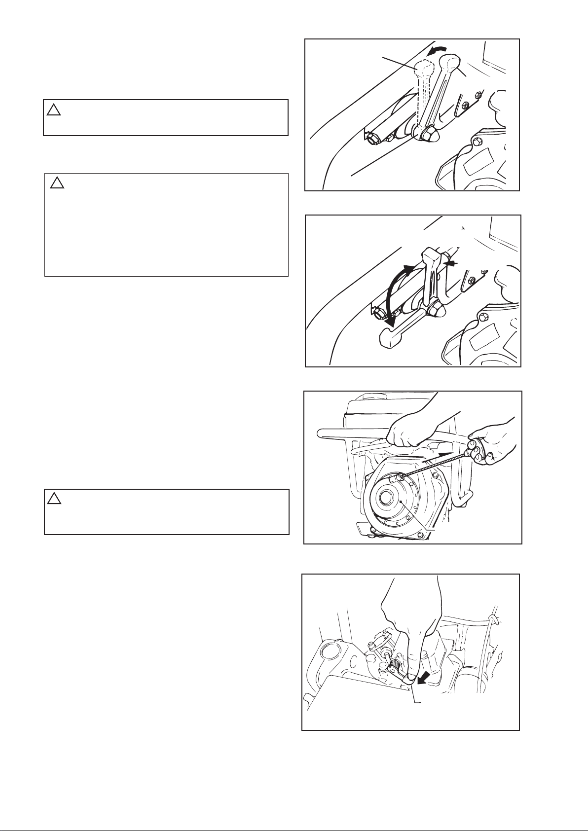
4.Starting
In cold weather, the engine should be
started at ope rating position or between
the idle and operation position of the
throttle lever.
Use caution as higher engine RPM. may
engage clutch, when engine starts.
Return throttle lever from starting position
to idle position when engine starts.
4 - 2 Grip the recoil starter handle and pull it
until you feel a slight resistance. (Fig.4)
4 - 3 Press the decompression lever to release
decompression.
The decompression lev er will return
automatically when the recoil starter is
pulled. (Fig.5)
4 - 4 Return the recoil starter, and pull the
handle sharply and quickly.
Warm up the engine by running at low
speed for three to five minutes, while
checking for fuel leakage or abno rmal
sounds.
Do no pull the s tarter rope all the way to the
end and do not let the starter rope snap back
as damage may result.
4 - 1 Move the throttle lever to IDLE position.
(Fig.3-1,3-2)
!
Throttle lever is used only at three (STOP,
IDLE & OPERATION) positions.
!
Idling position
Stop position
Throttle lever
Fig. 3-1
IDLE
Throttle
lever
OPERATION
Fig. 3-2
!
Recoil starter
Fig. 4
8
Decompression lever
(Decompressed posittion)
Fig. 5
Page 13

5 Operation
5-1 Move the throttle lever quickly from the IDLE to
OPERATION position to start tamping action. DO
NOT move the throttle lever slowly as this may
cause damage to the clutch or spring.
5-2 The tamping rammer is designed to tamp the
ground 650 to 700 times per minute for MT-76D at
an engine speed of 3,100 rpm.
Increasing the engine speed above the
recommended rpm will not increase the rammer
effectiveness.
Impact will actually decrease because a resonance
is created rather than a tamping effect, and
damage to the unit can result.
5-3 The rammer can be warmed by quickly moving the
throttle lever from the OPERATION to the IDLE
position several times until the rammer operates
smoothly.
5 -4 The tamping rammer is designed to travel forward
while tamping.
To increase travel speed, pull back slightly to the
handle so that the rear of the foot contacts soil
first.
5-5 To stop tamping, quickly move the throttle lever
from the OPERATION to IDLE position.
Do not move the lever slowly as irregular action
and damage may result.
6. Stopping the Engine
6-1 Move throttle lever quickly from idle to STOP while
pressing the throttle lever button.
Run the engine for three minutes at idle speed to
allow for proper cool down.
Following above procedure will prevent improper
cylinder lubrication caused by overheated
engine.(Fig.6)
Idling position
Stop position
Move the lever from Idling
to Stop position.
Throttle lever
Fig.6
9
Page 14

TEMPERATURE
CLASSIFICATION OF OIL
20 °C (+68 °F)or over
SAE 30
10 °C(+14 °F) - 20 °C(+68 °F)
SAE 20
B elow1 0 °C(+14 °F)
CC class or high er grade
SAE 10W - 30
!
7.Service
CAUTION:
Flammable Liquid. When refueling, stop engine and
allow it to cool. Do not smoke or allow work to be
performed in the immediate area. Fire or explosion
could result from flames or sparks, or if fuel is spilled
on a hot engine.
Moving Parts. Shut down the engine before performing
service or maintenance functions.
Contact with moving parts can cause serious injury.
High Temperatures. Allow machine and engine to cool
before performing service or maintenance functions.
Contact with hot components can cause serious
burns.
7 - 1 DAILY
* Thoroughly remove dirt and oil from the engine
and control area.
* Clean or replace air cleaner as necessary.
* Check and retighten all fasteners as necessary.
* Check spring box and bellows for oil leaks.
Repair as needed.
* Remove element from pre - cleaner at the top of
crankcase(body side) and clean it by air.
7 - 2 WEEKLY(every 50 hours)
* Remove the fuel filter cap and inspect clean fuel
tank.(Fig.7)
7 - 3 Replacement of Lubricant(BODY)
* Remove the drain plug at the rea r of tamper foot
and drain dirty oil. Refill with clean oil to the
middle of the sight glass. Oil bath contains
approx. 1.7 pt. (800 cc) for MT - 76D.
INITIAL OIL CHANGE:
After 50 hours of operation
SECOND OIL CHANGE AND/OR LATER:
Every 200 hours of operation
7 - 4 Replacement of Lubricant(ENGlNE)
7 - 4 - 1 While the engine is still warm, remove the
drain plug. For quick discharging, it is
advisable to take off the oil gauge.
Replace drain plug and refill engine
crankcase.(Fig.8)
7 - 4 - 2 Refer t he following chart, for oil types.
!
!
10
Fuel tank
Fuel filter
Fig.7
Drain plug
Fig.8
Page 15

The fuel filter is installed at the bottom of fuel
tank, should rammer be laid down dirt from
fuel filter may invade into injection nozzle and
fuel pump causing damage.
7-9 Storage
* When storing the rammer for long periods of
time, thoroughly drain all fuel from fuel line.
* Clean exterior of rammer with an oil-moistened
cloth. Cover and store in a clean, dry place.
7-4-3 The interval of oil replacement
INITIAL OIL CHANGE:
After 20 hours of operation
SECOND OIL CHANGE ANDIOR LATER:
Every 100 hours of operation
7-5 Cleaning the Air Cleaner
Cleaning the Air Cleaner (every 200- 300
hours) (Fig. 9)
* Remove element from pre-cleaner at the top
of crankcase(body side).
* Wash the element (outside) in detergent
solution.
* Shake out excess moisture and dry the
element.
* Clean inside element with air from the inside
of element.
7-6 Cleaning the Oil Filter
Drain oil filter every 100 hours of operation.
Replace the oil filter every 1,000 hours of
operation. (Fig.10)
7-7 Fuel Pipe & Oil Pipe
* Check fuel line regularly for damage, paying
attention to clamps to assure a tight fit.
* Replace fuel line every two years to maintain
original performance.
7-8 Transportation
Maintain upright position of rammer at all
times.
Transport rammer in upright position.
If machine must be laid down for
transportation, drain the diesel fuel first and
lay machine with muffler side down. (Fig.11)
Oil filter
Outer element
Inner element
Fig.9
Fig.10
Lay machine with
muffler side down
after draining the
diesel fuel.
Fig.11
11
Page 16

8. TROUBLE SHOOTING
1. Diesel Engine
(1) Starting Problem
(A) In case of compression problems
■
No compression at all
Intake/exhaust valve upthrust
Decompressor adjustment problems
■
Almost no compression
Contact with seat not close enough.
Piston ring wear
Cylinder wear
Cylinder, cylinder head mating surface problems
Nozzle seat looseness
(B) In case of inappropriate fuel injection inside the combustion chamber
■
Fuel flow low or no flow
Clogging of the tank cap air hole.
Clogging of the fuel filter
Fuel cock not open
Air inside the fuel pipe
■
Fuel not injected inside the combustion chamber
Injection pump barrel, plunger stuck
Nozzle hole clogging
Nozzle needle stuck
■
No fuel in the fuel tank
■
Mixing of water or foreign materials
(C) Fuel and compression pressure appropriate, but the engine does not start.
■
Does not reach the starting revolution.
Inappropriate starting operations
Engine oil viscosity high, engine oil is very dirty.
Air trapped inside the fuel pipe.
(2) Insufficient Output and Operation Problems
■
Insufficient compression
See the comment for insufficient compression.
■
Engine overheating with black smoke
Dirt and breakage of cooling fin
Mixing of water inside the fuel filter
Carbon accumulated in the combustion chamber or exhaust hole.
Smoke set inappropriate
Overload
Inappropriate injecting timing
Nozzle clogging
■
Revolution fluctuation
Governor fork and sleeve mating surface problems
Governor spring problems
Fly plate and sliding part wear and operation problems
12
■
Engine revolution does not increase.
Valve open/close timing inappropriate
Clogged exhaust hole, muffler
Overload
Page 17

■
Firing problem with white smoke (when unloaded)
Piston, cylinder ring wear
Nozzle hole clogging
Piston ring stuck
Wrong assembly (upside down) of piston ring
Inappropriate injection timing
Inappropriate valve open/close timing
Looseness of injection pump joint
■
Fuel consumption too high (black smoke)
Leakage from fuel passage
Clogging of the air cleaner element
Inappropriate fuel due to mixing of impurities
Overload
■
Extensive wear on sliding parts or stuck piston rings
Use of wrong oil
Failure to change oil
Breakage of the air cleaner element or failure to clean the air cleaner
■
Stopped suddenly with abnormal noise
Searing or damage of the piston, rod, etc.
■
Lubrication oil diluted and increased.
Wear on the injection pump barrel or plunger
■
Engine does not stop even though the fuel supply is cut (or over-running)
2. Rammer itself
Engine rotates but amplitude not uniform, or does not strike.
■
Too much oil
Wrong assembly of the governor system
Detached injection pump rack
Operating speed of throttle lever too slow.
Oil in excess.
Clutch slips.
Spring failure.
Set speed of engine improper.
13
Page 18

Note
- - - - - - - - - - - - - - - - - - - - - - - - - - - - - - - - - - -
- - - - - - - - - - - - - - - - - - - - - - - - - - - - - - - - - - -
- - - - - - - - - - - - - - - - - - - - - - - - - - - - - - - - - - -
- - - - - - - - - - - - - - - - - - - - - - - - - - - - - - - - - - -
- - - - - - - - - - - - - - - - - - - - - - - - - - - - - - - - - - -
- - - - - - - - - - - - - - - - - - - - - - - - - - - - - - - - - - -
- - - - - - - - - - - - - - - - - - - - - - - - - - - - - - - - - - -
- - - - - - - - - - - - - - - - - - - - - - - - - - - - - - - - - - -
- - - - - - - - - - - - - - - - - - - - - - - - - - - - - - - - - - -
- - - - - - - - - - - - - - - - - - - - - - - - - - - - - - - - - - -
- - - - - - - - - - - - - - - - - - - - - - - - - - - - - - - - - - -
- - - - - - - - - - - - - - - - - - - - - - - - - - - - - - - - - - -
- - - - - - - - - - - - - - - - - - - - - - - - - - - - - - - - - - -
- - - - - - - - - - - - - - - - - - - - - - - - - - - - - - - - - - -
- - - - - - - - - - - - - - - - - - - - - - - - - - - - - - - - - - -
- - - - - - - - - - - - - - - - - - - - - - - - - - - - - - - - - - -
- - - - - - - - - - - - - - - - - - - - - - - - - - - - - - - - - - -
- - - - - - - - - - - - - - - - - - - - - - - - - - - - - - - - - - -
- - - - - - - - - - - - - - - - - - - - - - - - - - - - - - - - - - -
- - - - - - - - - - - - - - - - - - - - - - - - - - - - - - - - - - -
- - - - - - - - - - - - - - - - - - - - - - - - - - - - - - - - - - -
- - - - - - - - - - - - - - - - - - - - - - - - - - - - - - - - - - -
- - - - - - - - - - - - - - - - - - - - - - - - - - - - - - - - - - -
- - - - - - - - - - - - - - - - - - - - - - - - - - - - - - - - - - -
- - - - - - - - - - - - - - - - - - - - - - - - - - - - - - - - - - -
- - - - - - - - - - - - - - - - - - - - - - - - - - - - - - - - - - -
- - - - - - - - - - - - - - - - - - - - - - - - - - - - - - - - - - -
- - - - - - - - - - - - - - - - - - - - - - - - - - - - - - - - - - -
- - - - - - - - - - - - - - - - - - - - - - - - - - - - - - - - - - -
- - - - - - - - - - - - - - - - - - - - - - - - - - - - - - - - - - -
Page 19

Page 20

MIKASASANGYOCO.,LTD.
1-4-3,Sarugakucho,Chiyoda-ku,Tokyo,101-0064,Japan
PRINTEDINJAPAN
 Loading...