

Page 1

CONCRETECUTTER
MCD-L14H
INSTRUCTIONMANUAL
en
http://www.mikasas.com
CODE
Contentsof“DeclarationofConformity”
PleaserefertheECDECLARATIONOFCONFORMITY
inthismanualaswell.
602-01507
*602-01507*
Page 2
S
㻤㻚㻞
㻡㻚㻟
㻤㻚㻟
'(&/$5$7,212)&21)250,7<
2) Manufacturer’s name and address.
3) Name and address of the person who keeps the
technical documentation.
7\SH9LEUDWRU\5DPPHUV
PRGHO
(TXLSPHQW
LWHPQXPEHU
6HULDOQXPEHU
SRZHUVRXUFH
FRQWRXWSXW
PD[RXW
0HDVXUHG
VRXQGSRZHU
OHYHOG%
*XDUDQWHHG
VRXQGSRZHU
OHYHOG%
2SHUDWRUV
VRXQGSUHVVXUH
OHYHOG%
XW!
MCD-1UBLH MCD-L14H MCD-218CEH
654118
Honda GX-200
3.7kW <4.1kW>
654179, 654180,
654181
For serial number, please refer it on front page.
Honda GX-200
3.7kW <4.1kW>
107 107 115
108 108 116
87 88 93
Mikasa Sangyo Co., Ltd.
4-3, Sarugaku-cho 1 chome, Chiyoda-ku, Tokyo101-0064, Japan
Takahiro Kishino, engineer
R&D Division, Mikasa Sangyo Co., Ltd.
Shiraoka-city, Saitama, Japan
654280, 654290,
654297, 654298,
654299
Honda GX390UT
6.6kW <8.2kW>
12) Conformity assessment according to Annex:
13) Name and address of the Notified Body
14) Related Directive
15) Declaration
16) Other related Community Directives
17) EC Conformity Certificate No:
18) Place and date of the declaration
+DQG$UP9LEUDWLRQ/HYHO
02'(/ $KYPVHF
MCD-1UBLH
MCD-L14H
MCD-218CEH
Vibration Level is in comply with EU Directive2002/44/EC and the value is
shown as 3 axix min. vibration level.
Test course ( Crushed gravel ) is in comply with EN500-4.
VIII (Full Quality Assurance procedure)
Société Nationale de Certification et d’Homologation (SNCH)
11, route de Luxembourg
L-5230 Sandweiler 䚷LUXEMBOURG
Directive(& and, to be followed by Directive (&,
relating to the noise emission in the environment by equipment for
use outdoors.
The equipment referred in this document, fulfills with all the
requirements of Directive 2000/14/EC
(&(&(&(&(&
EN500-1, EN500-4
SNCH*2000/14*2005/88*0472*04
Tokyo, Japan June, 2016
Signed by:
Keiichi YOSHIDA
Director, R&D Division
Mikasa Sangyo Co., Ltd.
5HPDUNV
The above values are subject to change in case that the machine is modified
or/and the required regulations change.
Page 3

Italian
Garanzia di Qualità totale )
1. DICHIARAZIONE “CE” DI CONFORMITÁ
2. Nome e indirizzo Fabbricante
3. Nome e indirizzo della persona che conserva la
documentazione tecnica
4. Tipo: Piastre vibranti
5. Modello
6. Codice macchina
7. Numeridi matricola
8. Potenza installata netta <resa massima>
9. Livello di potenza sonora misurato (dB)
10. Livello di potenza sonora garantito
11. Livello massimo di pressione sonora
12. Valutazione di conformità in accordo all'annesso VIII
( procedura Garanzia di Qualità totale
13. Nome dell'organismo notificato
14. Rappresentante Autorizzato in Europa
15. Direttiva di riferimento
13. Nom et adresse de l'organisme notifié
14. Mandataire dans la Communaute Europeenne
15. Directive concernee
Est egalement conforme aux dispositions de la directive
<<emission sonores des equipements utilises a l'exterieur
des batiments>> 2000/14/CE et aux legislations nationales
la transposant.
16. Declaration
L'équipement de référence satisfait aux exigences de la
Directive 2000/14/EC
17. Autres directives communautaires concernees
18. Certificate deConformite CE numero:
19. Lieu et date de la declaratio
Spanish
1. DECLARACIÓN “CE” DE CONFORMIDAD
2. Nombre y dirección del fabricante
Direttiva 2000/14/CE su l'emissione acustica ambientale
delle macchine ed attrezzature destinate a funzionare
all'aperto
16. Dichiarazione
Le attrezzature riportate nel documento soddisfano i requisiti
della Direttiva 2000/14/CE
17. Altre Direttive Comunitarie di riferimento
18. Certificato di Conformità CE No:
19. Luogo e data della dichiarazione
French
1. DECLARATION « CE » DE CONFORMITE
2. Non et adresse du Fabricant
3. Nom et adresse de la personne qui défient les documents
techniques
4. Type du materiel: Plaques vibrantes
5. Modello
3. Nombre y dirección de la persona que guarda la
documentación técnica.
4. Tipo: Bandejas vibrantes
5. Modelo
6. Número de referencia del equipo
7. Numeros de serie
8. Potencia neta instlada <rendimineto maximo>
9. Nivel sonoro medido del motor ( dB )
10. Nivel sonoro garantizado del motor ( dB )
11. Máximo nivel sonoro de presión ( dB )
12. Evaluación de la Conformidad de acuerdo al Anexo VIII
( Prcedimiento de total garantía asegurada )
13. Nombre y dirección de la Entidad Notificada
14. Representante autorizado
15. Directiva relacionada
Directiva 2000/14/CE en relación a la emisión sonora en el
ambiente por equipos que trabajan en espacios abiertos
6. Numero equipement
7. Numéro de série
8. Puissance reseau <rendement maximal>
9. Niveau sonore mesure(dB)
10. Niveau sonore garanti(dB)
11. Niveau sonore maximum
12. Certification de conformite selon l'annexe VIII ( procedura
16. Declaración
El equipo referido en este documento , cumple con todos los
requerimientos de la Directiva 2000/14/EC
17. Otras Directivas Comunitarias relacionadas
18. Certificado de Conformidad CE Nº
19. Lugar y fecha de la declaración
Page 4

TABLE OF CONTENTS
INTRODUCTION ......................................................................................
1.
MACHINERY OVERVIEW ........................................................................
2.
WARNING SIGNS ....................................................................................
3.
CAUTIONS FOR SAFETY........................................................................
4.
General Cautions
4.1
Refueling Precautions
4.2
Location And Ventilation Precautions
4.3
Precautions Before Starting
4.4
Precautions During Work
4.5
Lifting Precautions
4.6
Precautions In Transportation / Safekeeping
4.7
Precautions In Maintenance
4.8
Installed Place Of Every Decal
4.9
4.10
APPEARANCE.........................................................................................
5.
SPECIFICATION......................................................................................
6.
BEFORE STARTING YOUR OPERATION...............................................
7.
OPERATION ............................................................................................
8.
STOPPING...............................................................................................
9.
TRANSPORTAION...................................................................................
10.
10.1
10.2
STORAGE.................................................................................................
11.
PERIODIC CHECK AND COORDINATION..............................................
12.
TROUBLESHOOTING .............................................................................
13.
13.1
13.2
Warning Labels And Information
Dimensions
5.1
Parts And Compornent
5.2
Main Body
6.1
Engine
6.2
Starting Up
8.1
Working
8.2
Loading And Unloading
Precautions In Transportation
Gasoline Engine
Machine
1
1
2
2
2
3
3
3
4
4
5
5
5
6
7
7
8
9
9
9
10
13
13
14
14
15
15
15
16
17
18
18
19
Page 5

1䠊INTRODUCTION
TThis instruction manual describes the proper methods for using Mikasa CONCRETE CUTTER, as well as simple
䖃
checks and maintenances. Be sure to read this instruction manual before operation, in order to get full use of the excellent performance of this machine, as well as to improve your operation and to perform engineering work effectively.
After reading this manual, store it in a handy location for easy reference.
䖃
For details about the engine of this machine, see the separate instruction manual.
䖃
For inquiries about repair parts, parts lists, service manuals, and repairs, please contact the store where you purchased
䖃
the product, our sales office, or the Mikasa Parts Service Center. For parts lists, please visit our homepage at:
http://www.mikasas.com/ where you can access Mikasa WEB parts lists.
The illustrations in this manual might slightly differ in part from the machine you actually
purchased due to design changes.
2䠊MACHINERY OVERVIEW
Application
Mikasa Concrete Cutter is used to cut the concrete or asphalt road surface by Diamond Blade that is attached on its Blade
shaft. Please choose machine type by cutting depth, and then choose appropriate blade to match the spot situation, such as
material age, presence or absence of reinforcement in the concrete.
Warning About Incorrect Applications And Techniques
Please use this machine to cut plain concrete, reinforced concrete and asphalt only.
Do not cut sediment, for that it flies into pieces and injuries man around the machine.
This cutter can be equipped with diamond blade only. Do not attach resinoid blade on this machine. Please pour water to
blade at cutting except using dry-type blade, for that conglutination of the blade or Blade chip flies into pieces.
Do not use this machine in the state that you turned more than the number of turn in accord with the blade, for that conglutination of the blade or Blade chip flies into pieces.
Do not use this machine in instability, or in a rough ground, for that conglutination of the blade or Blade chip flies into pieces.
Do not use this machine to cut a secondary product concrete.
Structure
Engine of Concrete Cutter is fixed on a main body base, and conveys power to Blade shaft with the V belt. The way of adjustment of V-belt tension is making Engine slide.
Belt cover, Handle guide, Handle for elevating the blade, and Blade cover which can be put on and off easily is attached on
Engine Base. Cutting depth is adjusted by rotating Handle for elevating the blade through Blade Arm that is equipped with
Front wheel The way to travel the machine is pushing the machine directly.
Power Transmission
Air-cooled petrol engine is amounted on Mikasa Concrete Cutter as power source.
V-pulley is attached on Engine shaft for driving Blade shaft, and Diamond Blade is attached on Blade shaft. The cutting depth
can be adjusted to change the Front wheel position by Handle.
The way of driving the machine while cutting is pushing the handle.
1
Page 6

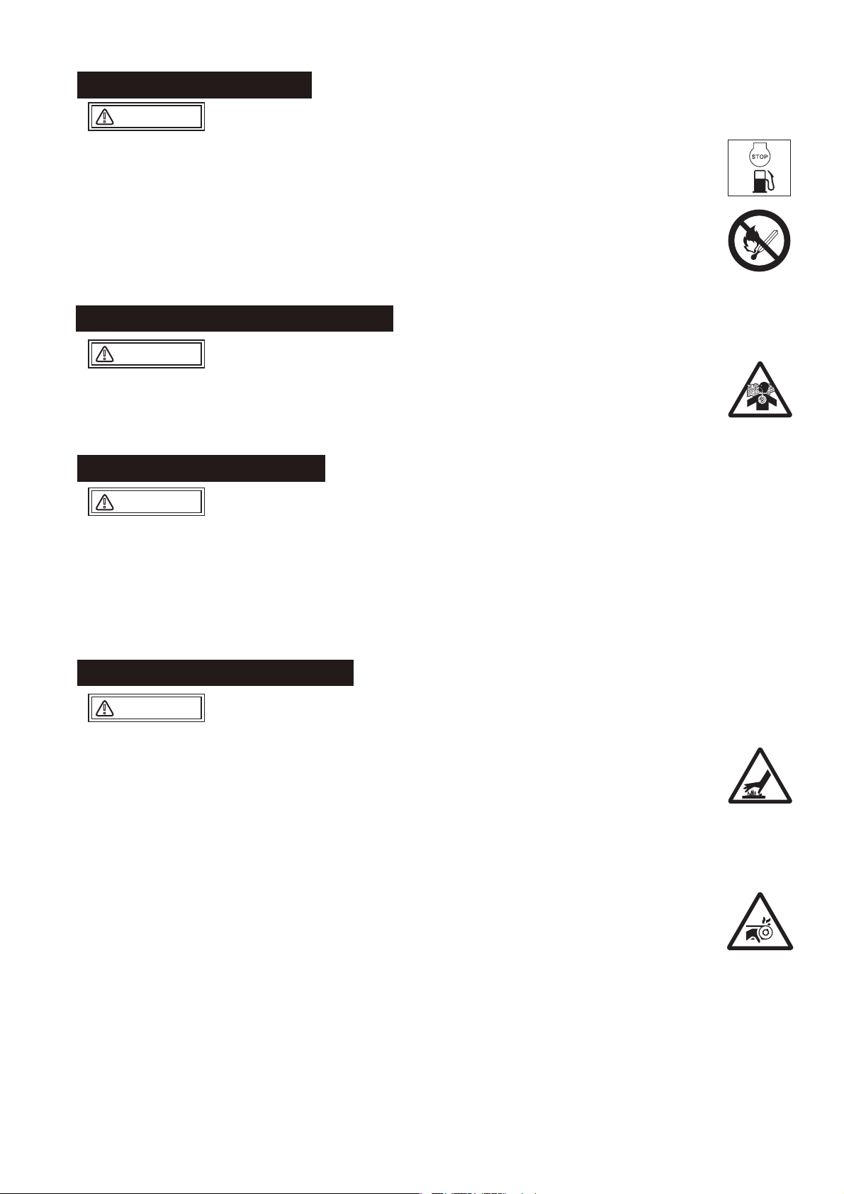
3䠊WARNING SIGNS
The triangle shaped marks used in this manual and on the decals stuck on the main body
indicate common hazards. Be sure to read and observe the cautions described.
Warning labels indicating hazards to humans and to equipment.
䟿
Denotes an extreme hazard. It calls attention to a procedure, practice,
䟿
DANGER
䟿
WARNING
䟿
CAUTION
condition or the like, which, if not correctly performed or adhered to, is
likely to result in serious injury or death.
Denotes a hazard. It calls attention to a procedure, practice, condition
or the like, which, if not correctly performed or adhered to, could
result in serious injury or death.
Denotes a hazard. It calls attention to a procedure, practice, condition
or the like, which, if not correctly performed or adhered to, could
result in injury to people and may damage or destroy the product.
CAUTION
(without at )
Failure to follow the instructions may result in damage to property.
䟿
4䠊CAUTIONS FOR SAFETY
4.1 General Cautions
䟿
WARNING
Do not work with this machine, when
䖃
䟿
Read this instruction manual carefully and handle the machine as described so that you
䖃
can work safely.
For details about the engine, refer the separate instruction manual for the engine.
䖃
Make sure you thoroughly understand the construction and operation of the machine.
䖃
Please check each part before work, and execute the scheduled check and alignment
䖃
regularly.
To work safely, always wear protective clothing (helmet, safety glasses, safety shoes,
䖃
ear plugs etc.) and appropriate work clothes.
Please wear Hearing protector ( noise protective equipment of ear muff or ear stoppers)
䖃
by all means.
Always check the machine to make sure that it is normal before starting operation.
䖃
The decals on the machine body (operating methods, warning decals, etc.) are very im-
䖃
portant to ensure safety. Keep the machine body clean so that they can be read at all
times. If any decal cannot be read, replace it with a new one.
It is very dangerous if children come into contact with the machine. Take the utmost
䖃
care how and where the machine is stored.
Before performing any maintenance, be sure to turn the engine off.
䖃
Mikasa does not accept any liability for accidents or problems caused as a result of not
䖃
using genuine Mikasa parts or if the machine has been modified.
you are tired or sick and not feeling well,
䕿
you have taken medicine or drug, or
䕿
you have had a drink.
䕿
CAUTION
2
Page 7
4.2 Refueling Precautions
䟿
DANGER
Always refuel in a well ventilated area.
䖃
Make sure to stop the engine and wait until the engine cools down when refueling.
䖃
Select a flat surface area with no flammable material around for refueling. Be careful
䖃
not to spill the fuel. Wipe off well if there is any spill.
Never put fire near the machine during refueling. (Especially, be careful about
䖃
smoking.)
If you fill to the top of the fuel tank inlet, fuel might spill out from the tank, and it
䖃
becomes dangerous
After refueling, tighten the tank cap well.
4.3 Location And Ventilation Precautions
䟿
DANGER
Do not run the machine in an unventilated location, such as indoors or inside a tunnel.
䖃
The exhaust gas from the engine contains toxic gases such as carbon monoxide and
is very hazardous.
䖃
Do not operate the machine near open flames.
4.4 Precautions Before Starting
䟿
CAUTION
Check the clamping condition of each part. Cause the big failure that does not think
䖃
that a screw loosens by vibration. Tighten the screw well.
Confirm that the diamond blade does not have anomaly such as deficit of the blade
䖃
chip or the crack of the board.
If the machine were not run more than 3 months, be sure to start at low speed in a
䖃
few minutes to warm up thoroughly,
for the reason to avoid engine seizure by oil film shortage.
4.5 Precautions During Work
䟿
CAUTION
When starting and working with the machine, confirm that neighboring people and
䖃
obstruction are safe.
Always pay attention to foothold and work in easy position that allow to keep your
䖃
machine in good balance.
Be careful not to touch muffler and engine body as it becomes hot in operation or just
䖃
after operation.
Discontinue operation promptly whenever your machine goes deficient or you notice
䖃
any abnormality.
Be sure not to make the cutter with blade stand-by for work.
䖃
In the case to be without avoidance, be sure to run the engine at low speed possibly
in a short time.
(In case of running the engine at high speed at the above position for long time, it
might occur the engine seizure by oil film shortage.)
Be sure to stop engine before leaving the machine. Also shutdown engine for
䖃
transporting the machine, and close the fuel cock.
Mount blade cover by all means, and use it.
䖃
Because engine turns blade when start, be careful enough. Do not bring legs close
䖃
especially.
Be careful enough so that be not rolled up your hand or clothes in reel (inside of the
䖃
belt cover).
3
Page 8

4.5 Precautions During Work
䟿
DANGER
Precautions in inclined area
When you use machine on inclined area, various risk is accompanied. Adhere
rigidly to the following precautions to a minimum, and try for further safety
retention. When you cannot get safety, never use it.
Do not leave machine in the inclined area. There is danger to cause a serious
䖃
accident when machine begins to move by any chance.
In the inclined area, grasp a handle well, and never separate a hand from machine.
䖃
Machine begins to move in tare weight at the moment when you separated a hand,
and there is danger to cause a serious accident.
Because there is the danger that machine runs uncontrollably when a grip falls out
䖃
from the handle, warn you enough.
When you work in inclined area, be located in the upper part of the slope for machine
䖃
by all means, and let machine face straight it below for a slope, and work.
䖃
Stop the machine at flat space. When you stop machine in
inclined area out of necessity, lower straight machine after
having stopped the engine by all means, do ring stopper to the
front wheel for safe retention by all means. When be collided by
an automobile and be shaken in right and left, even if you put on
ring stopper down the front wheel, the machine climbs ring
stopper and begins to move, and be careful this risk is very likely.
Even if you put on ring stopper down the back wheel, there is not
effect. In addition, a parking brake of the rear wheel is not a thing
to guarantee certain fixation of the machine. Use ring stopper for
a front wheel on the occasion of a stop by all means.
When put ring stopper, never go in the front side of the machine. When machine has
䖃
begun to move by any chance. There is the danger of serious injury or decease, by
the physical truncation with blade and the conflict of machine.
If hand touches the blade when put ring stopper, there is danger injured seriously. Put
䖃
ring stopper from the non blade cover side of the machine by all means.
In case of stop, when water is in the water tank, the center of gravity rises and the
䖃
balance worsens . Even if you put ring stopper to the front wheel at the time, it is very
dangerous that the front wheel climbs over ring stopper and begins to move. In this
case pull water out of the water tank by all means.
When a road surface gets wet in inclined area, ring stopper in itself slips depending
䖃
on an angle, and effect is gone. Stop on the dry road surface by all means, when you
stop it in inclined area out of necessity.
Do not work on blade installation disassembly in inclined area, because it is
䖃
dangerous.
Do not work on to cross the slope. There is danger that tumble of the machine or the
䖃
damage of the blade cause a serious accident.
4.6 Lifting Precautions
䟿
DANGER
Be sure to work with sling by crane license holder.
䖃
Before work of lifting, check any damage of body parts (especially, Lifting hook, etc)
䖃
or looseness / omission of screws, and be sure safe.
Stop the engine at the time of the lifting, and close the fuel cock.
䖃
Use enough strength of wire rope.
䖃
The work of lifting uses only one-point lifting hook, and do not lift in other point
䖃
(handles).
Never put any person or animal under the lifted machine.
䖃
For safety, do not lift up the machine more than required height.
䖃
4
Page 9
4.7 Precautions In Transportation / Safekeeping
䟿
WARNING
Stop the engine at the time of transportation.
䖃
Carry it after engine and body got cold well.
䖃
By all means drain fuel before transporting the machine .
䖃
Fix the machine well not to move and fall down.
䖃
4.8 Precautions In Maintenance
䟿
CAUTION
Appropriate maintenance is always required for safety operation and to maintain
䖃
performance of the machine. Pay full attention in the condition of the machine, and
maintain good condition. Especially improper maintenance of lifting-related part
becomes cause of serious accident.
Do work after lower temperature of machine. Especially muffler becomes high
䖃
temperature, and there is danger that burn itself. In addition, be careful not to burn
itself enough, because engine or engine oil become hot.
Do the check alignment in situation that stopped engine by all means. There is badly
䖃
injured danger when you are rolled up in a reel.
After maintenance fulfillment, check the installation of safety protection parts and
safety of the machine. Especially, check bolts and nuts thoroughly.
When you do maintenance with dismantlement, refer to maintenance manual
regularly, and work safely.
4.9 Installed Place Of Every Decal
12
11
㻺㻻㻚
㻼㻭㻾㼀㻛㻺㻻㻚
㻡
㻥㻞㻜㻝㻙㻜㻝㻞㻜㻜 㻰㻱㻯㻭㻸㻘㻌㻳㻾㻱㻭㻿㻱㻌㻛㻺㻼㻙㻝㻞㻜
㻥㻞㻜㻝㻙㻜㻥㻢㻥㻜
㻢
㻥㻞㻜㻝㻙㻝㻜㻜㻡㻜
㻝㻜
㻝㻝 㻥㻞㻜㻝㻙㻜㻜㻥㻞㻜
㻝㻞
㻥㻞㻜㻝㻙㻜㻝㻟㻥㻜
㻥㻞㻜㻞㻙㻜㻥㻤㻝㻜
㻝㻟
㻝㻠
㻥㻞㻜㻞㻙㻝㻜㻝㻞㻜
㻝㻡
㻞㻝
㻥㻞㻜㻞㻙㻝㻜㻢㻥㻜
㻰㻱㻯㻭㻸㻘㻌㻱㻹㻮㻸㻱㻹㻛㻯㼁㼀㼀㻱㻾
㻰㻱㻯㻭㻸㻘㻌㻹㻻㻰㻱㻸㻌㻹㻯㻰㻙㻸㻝㻠
㻰㻱㻯㻭㻸㻘㻌㻹㻙㻹㻭㻾㻷㻌㻔㻠㻜㼄㻤㻜㻕
㻰㻱㻯㻭㻸㻘㻌㻹㻵㻷㻭㻿㻭㻌㻔㻞㻡㻜㻕
㻰㻱㻯㻭㻸㻘㻌㼂㻙㻮㻱㻸㼀㻌㻟㼂㻙㻞㻢㻡
㻼㻸㻭㼀㻱㻘㻌㻿㻱㻾㻵㻭㻸㻌㻺㻻㻚
㻰㻱㻯㻭㻸㻘㻌㻵㻺㻰㻵㻯㻭㼀㻻㻾㻛㻹㻯㻰㻝㻞㻙㻞㻜㻜
㻰㻱㻯㻭㻸㻘㻌㻯㻭㼁㼀㻵㻻㻺㻔㻵㻯㻻㻺㻕㻛㻱㼄㻼
10
5
14
6
21
10
㻡
㻼㻭㻾㼀㻌㻺㻭㻹㻱
13
㻽㻓㼀㼅
㻝
㻞
㻞
㻝
㻝
㻝
㻝
㻝
㻝
㻾㻱㻹㻭㻾㻷㻿
5
Page 10
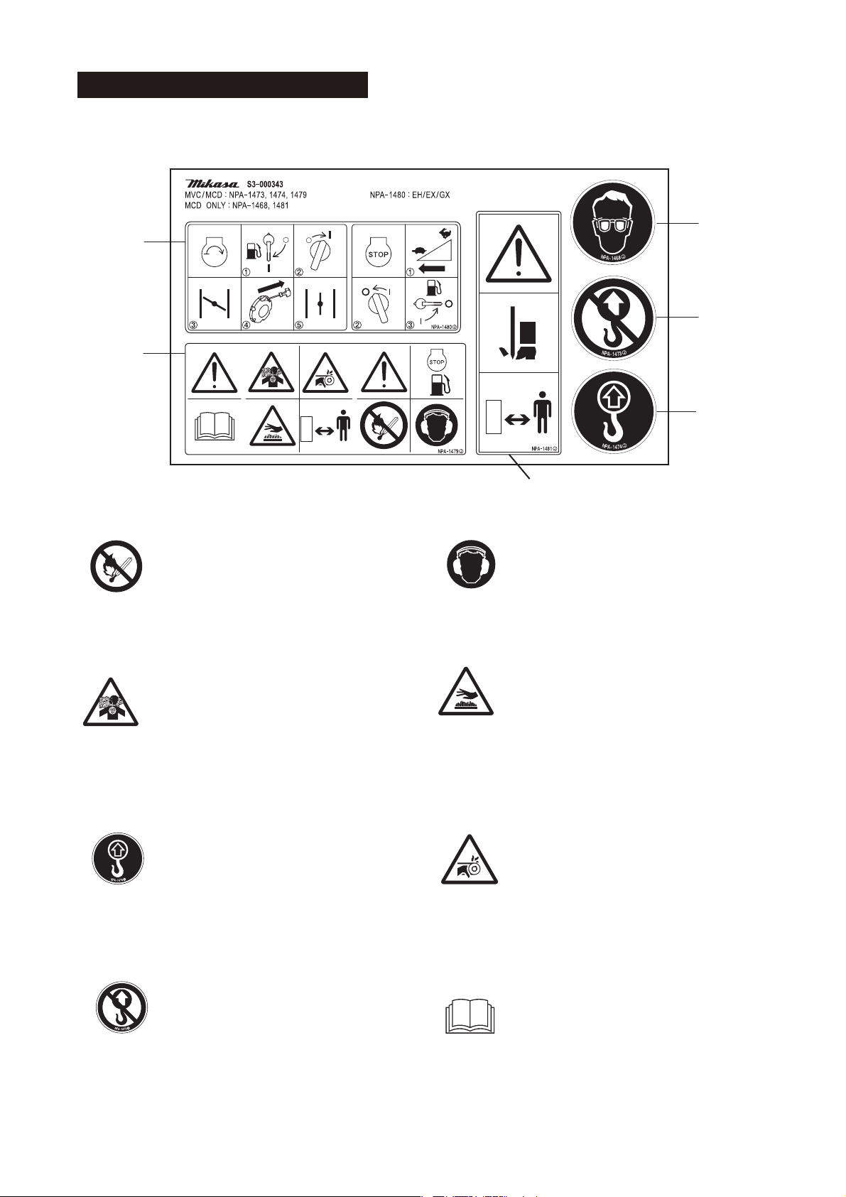
4.10 Warning Labels And Information
Decal for new European machine directives
NPA-1480
NPA-1479
䐟
3$5712
㻰㻱㻯㻭㻸㻘㻌㻿㻱㼀㻌㻛㻹㼂㻯㻘㻌㻹㻯㻰㻌㻛㻱㼄㻼㻘㻱㼁㻌
Fire hazard
Stop the engine when refueling. Fire
may occur if a flame is near the tank
fuel port.
䐣
NPA-1468
NPA-1473
NPA-1474
NPA-1481
Danger of hearing damage caused
by noise
Always use ear plugs while operating
the machine.
䐠
䐡
䐢
Danger: poisonous exhaust gas
Carbon monoxide poisoning may
occur if the exhaust gas is inhaled. Do
not operate the machine in a poorly
ventilated area.
Do not go under the lifted machine.
Do not let people or animals go under
the lifted machine.
Lifting by the handle is prohibited.
Due to a falling risk, do not lift the
machine by the handle.
䐤
䐥
䐦
Be careful not to get burned.
Accidental burn may occur if you touch
the hot parts (engine, muffler, etc.)
during operation or immediately after
the machine stops.
Be careful not to be caught in
rotating parts.
Make sure the engine is stopped when
removing the belt cover during a belt
change.
Read the manual carefully.
Always read the operation manual and
have good understanding of operation
before your work.
6
Page 11
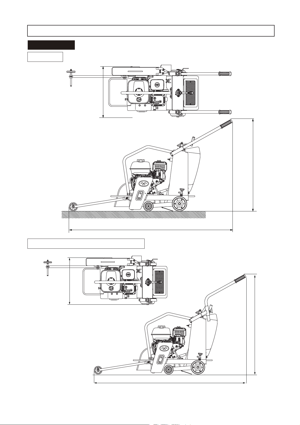
5䠊APPEARANCE
5.1 Dimensions
MCD-L14
(mm)
527
930
MCD-L14 ( with Special handlebar )
527
1650
1030
7
1630
Specifications are subject to change without notice.
※
Page 12
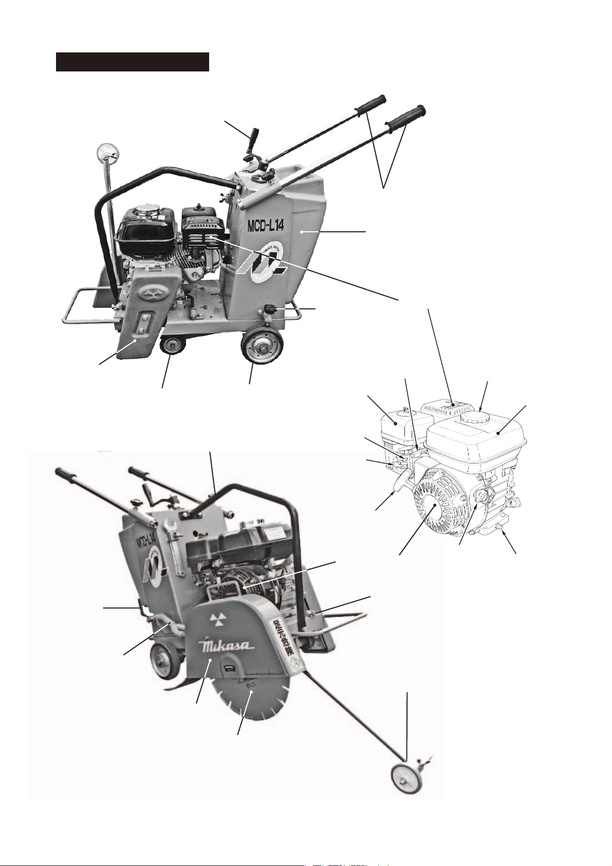
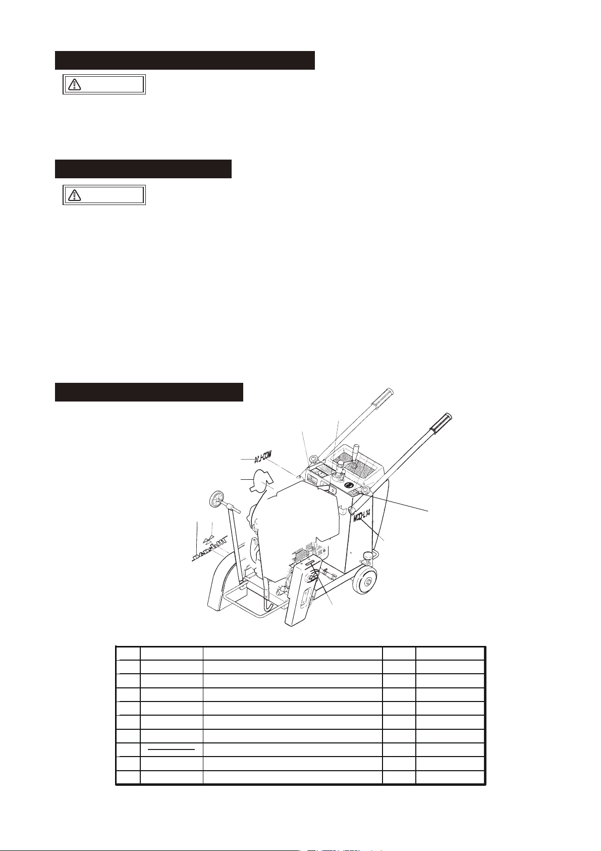
5.2 Parts And Compornent
Lifting handle
Handle
Water tank
Belt cover
Water cock
Front wheel
Hook
Rear wheel
Parking brake
Air cleaner
Choke lever
Fuel cock
Starter knob
Recoil starter
Muffler
Throttle lever
Switch
(ON-OFF)
Adjusting bolt & nut
of the belt tension
Fuel tank cap
Fuel tank
Drain plug
Sprinkling pipe
Line gauge
Blade cover
Diamond blade
8
Page 13
6䠊SPECIFICATION
6.1 Main Body
Model
Power source ( Engine model )
Dimensions
Overall Length ( on operating )
Overall Width
Overall Height
Operating Weight
Traveling system
Adjusting for cutting depth
Cooling System of blade
Water tank capacity
Blade size and maximum cutting depth ( Axis hole dimension of bladeφ27)
Blade size (Outer diameter)
(10in.) 254mm
(12in.) 305mm
(14in.) 356mm
Limitation of Blade size
Weight includes weigh of machine, lubricants, 50% of fuel and 50% of water in case with
※
water tank option.
Specifications are subject to change without notice.
※
[ with Special handlebar ]
Manual lifting screw system
Centrifugal injection type
Maximum cutting depth
MCD-L14H
GX200
1650mm [1630mm ]
527mm
930mm [1080mm ]
100kg
Hand push type
26L
70mm
95mm
120mm
Under 14in.
6.2 Engine
Manufacturer/
Type
Max. Output
Fuel tank capacity
Model
HONDA, GX200
Air-cooled 4-cycle petrol engine
4.1kW/3600min
(5.6PS/3600rpm)
3.6L
-1
9
Page 14
7䠊BEFORE STARTING YOUR OPERATION
DANGER:
Do the check alignment in situation that stopped engine
䚷㻌㻌㻌㻌
by all means. There is badly injured danger when you
are rolled up in a reel.
䚷㻌㻌㻌㻌㻸㼑㼢㼑㼘㻌㼠㼔㼑㻌㼙㼍㼏㼔㼕㼚㼑㻘㻌㼍㼚㼐㻌㼏㼔㼑㼏㼗㻌㼕㼠㻌㼍㼒㼠㼑㼞㻌㼠㼔㼑
㻌㻌㻌㻌㻌㻌㼙㼍㼏㼔㼕㼚㼑㻌㼏㼛㼚㼒㼕㼞㼙㼑㼐㻌㼠㼔㼍㼠㻌㼕㼠㻌㼐㼛㼑㼟㻌㼚㼛㼠㻌㼙㼛㼢㼑㻚
㻌㻌㻌㻌㻌㻌
ۻ
䚷㻌㻌㻌㻌㼀㼔㼑㻌㼏㼔㼑㼏㼗㻌㼜㼛㼕㼚㼠㻌㼎㼑㼒㼛㼞㼑㻌㼠㼔㼑㻌㼣㼛㼞㼗㻌㼟㼑㼑㻌㻎㼑㼍㼏㼔㻌㼜㼍㼞㼠
㻌㻌㻌㻌㻌㻌㼏㼔㼑㼏㼗㻌㼟㼏㼔㼑㼐㼡㼘㼑㻌㼘㼕㼟㼠㻎㻌㼙㼑㼚㼠㼕㼛㼚㼑㼐㻌㼕㼚㻌㻝㻣㻌㼜㼍㼓㼑㼟㻚
1
Engine oil (Fig.1)
With the engine positioned horizontally, check
oil-with oil gauge.
Replenish through filler port as necessary. Use
following oil
(10W-30 is in use when shipped).
SAE#30 (for normal temperature)
SAE#20 (for 10 or lower)
SAE#10W-30
This oil can be used throughout the year
regardless of ambient temperature (up to
ambient temperature -20 䉝㻌).
When it is used in normal temperature, its
consumption tends to increase. Pay additional
attention at the time of daily check. As for quality
of oil, be sure to use SE grade or better.
Degraded quality or decreased quantity may
induce damage by seizure.
Fuel
2
Use lead-free automobile gasoline. For
replenishment, be sure to shutdown engine and
use strainer provided at filler port. Wipe off any
spilled fuel clean.
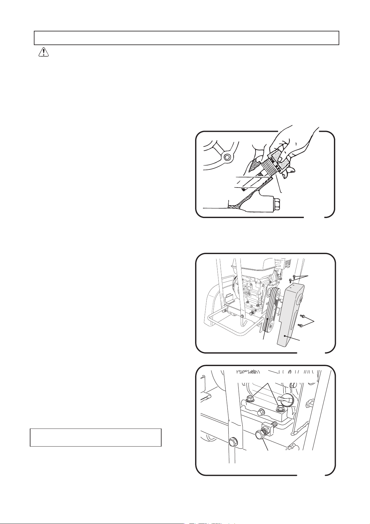
V-belt
3
Check V-belt for any slack or damage. Tension is
proper if the belt bends about 10mm when
pressed with your finger at midway between two
shafts. Retighten as necessary but when
replacing, replace both of them simultaneously.
Place the usable one in stand-by parts. For
adjusting the tension, slide engine longitudinally.
㻹㼍㼤㻚㻌㻸㼑㼢㼑㼘
㻹㼕㼚㻚㻌㻸㼑㼢㼑㼘
㻌㻔㻾㼑㼜㼘㼑㼚㼕㼟㼔㻕
㻻㼕㼘㻌㻳㼍㼡㼓㼑
V-belt
Engine mounting bolts
Fig.1
Bolt
Bolt
Belt cover
Fig.2
Adjusting the belt
A With 4 bolts removed, take off belt cover.
(Fig.2)
B Loosen 4 engine mounting bolts.
Caution:
Bolts should be just loosened;
not removed.
C Rotating it clockwise increases the belt
tension. (Fig.3)
Adjusting bolt & nut
of belt tension
Fig.3
10
Page 15

Water tank
4
Use water tank filled with water.
Useful life of blade depends on volume of cooling
water.
Pay attention to the water level.
(Fig.4)
Sprinkling pipe
5
Open the cock to make sure that sprinkler pipe is not
clogged.
(Fig.4).
Installing the blade:
6
a.
Disconnect water pipe at the nipple of water tank side.
Remove the blade cover by lifting it upward.
b.
Place flange (IN), diamond blade and flange (OUT)
around the blade shaft in such order, and install
washer before tightening sufficiently with nut (left-hand
thread). (Fig.5, 6)
Water Tank
Water Cock
Flange
(OUT)
Blade cover
Fig.4
Flange(IN)
Caution:
With wrench engaged at designated location of the
blade shaft to lock it, rotate nut counterclockwise to
tighten. (Fig.6)
c.
After installing the blade, replace blade cover to base ,
before replacing water hose to nipple firmly. And
check the cooling water.
Cutting depth adjustment:
7
To unlock, set the knob to shallow groove.
This will enable you to exactly adjust the cutting depth
by turning the lifting handle.
To lower (feed motion) the machine body, rotate lifting
handle clockwise.
To raise the body, rotate the lifting handle counterclockwise.
When decided the cutting depth, set the knob at lock
position for lock the position of machine. (Fig.7)
Washer
Diamond blade
Nut
30mm(L14)
Tightening
Raise
Lower
(Feed motion)
To lock the lift or lower the machine, set
the knob to deep groove.
To unlock, set the knob to shallow groove.
Fig.5
27mm(L14)
Fig.6
㻯㼞㼍㼚㼗㻌㻴㼍㼚㼐㼘㼑
㻌㻌㻌㻌㻌㻔㻯㼡㼠㼠㼕㼚㼓㻌㼐㼑㼜㼠㼔㻌
㻌㻌㻌㻌㻌㻌㻌㻌㼍㼐㼖㼡㼟㼠㼙㼑㼚㼠㻕
Fig.7
11
Page 16

8.
Move each operation lever, and check on creak or
the wobble.
Check bolts and nuts for looseness or any other
9.
abnormality.
10.
Parking brake
There is a parking brake to left back wheel.
Turn a knob to right (a clock direction) and brake
it, and turn it to the left and remove brakes.
Remove brakes before the work. (Fig.8)
11.
Cut depth reading method
Cut depth is distance from the reading point of
Fig. 9 to blade tip.
There is blade tip in circumference of blade.
When you cut asphalt or concrete road with
diamond blade, the line trace (trace of line) of turn
happens on the side surface of blade.
Search the line trace of reading point, and read
distance from circumference to it with the scale of
blade cover. (Fig.9)
Parking brake
Reading point
Diamond Blade
Cut depth
Fig.8
Blade Cover
Scale
Trace of line
Circumference
Surface
of earth
Fig.9
12
Page 17

8䠊OPERATION
8.1 Starting Up
Move fuel cock lever with “ON” position.
㻝㻚
(Fig.10)
Fuel cock lever
DANGER:
㻞㻚
When cold or somehow starting is difficult, turn
The exhaust gas from the engine is carbon
monoxide and is deadly.
Do not run the engine in an unventilated
location, such as indoors or in a tunnel.
choke lever to START position. This is not necessary when engine is warm. (Fig.11)
㻟㻚
Move throttle control lever slightly to high speed
side. (Fig.11)
㻠㻚
Turn engine start switch to ON position.
(Fig.12)
㻡㻚
Hold recoil starter grip and pull it slightly until you
feel light resistance. Pull it strongly there. Be careful not to pull it too hard because it may come off.
Do not release the grip from the pulled position but
return it to starter case before releasing. (Fig.13)
䇾㻻㻲㻲䇿
Throttle control
lever
High speed
Choke lever
Choke close
(START)
ON/OFF Switch
IN (ON)
䇾㻻㻺䇿
Fig.10
Low ( Idling )
Choke open
OPERATION)
(
Fig.11
If engine has started, while listening to explosion
㻢㻚
sound, slowly return the choke lever to OPERATION position. (Fig. 11)
After started, be sure to run the engine at low
speed for a few minutes.
It must be done in cold weather particularly . Check
for abnormal noise or gas leak in the meantime.
DANGER:
CAUTION:
Because engine turns blade when start,
be careful enough.
Do not allow the starter grip to snap back
against the engine.
Return it gently to prevent damage to the
starter.
Fig.12
Starter grip
Fig.13
13
Page 18

8.2 Working
1.
Align the blade with cutting line. Aligning is easier if it is
done with the machine lifted.(Fig.14)
2.
With water cock opened, spray cooling water to the
blade. At least 5-6 liters per minute of cooling water
is required.
As the standard, if water mist is being sprayed to the
extent that water does not flow, the cooling will be
sufficient. Adjust the amount of water with cock.
(Spray on a little heavier side when there is sufficient
water.) (Fig.15)
Gauge
Blade
Cutting line
Fig.14
3.
Open throttle lever slowly to set engine revolution to
high speed. (Fig.11)
4.
To cut - in with the blade at the bottom, turn the Crank
handle to clockwise, and cut down while adjustment
the lowering speed so that engine speed is not
reduced excessively. After cutting down, set the knob
to the lock position which located beside of Crank
handle to lock the machine. (Fig.16)
5.
While listening to engine sound, push the machine
slowly for cutting operation.
Caution: Sudden feeding or cutting may
damage blade or decrease durability
of engine, V-belt, etc..
Water cock
Close
Open
Fig.15
Raise
㻯㼞㼍㼚㼗㻌㻴㼍㼚㼐㼘㼑
㻌㻌㻌㻌㻌㻔㻯㼡㼠㼠㼕㼚㼓㻌㼐㼑㼜㼠㼔㻌
㻌㻌㻌㻌㻌㻌㻌㻌㼍㼐㼖㼡㼟㼠㼙㼑㼚㼠㻕
Lower
(Feed motion)
To lock the lift or lower the machine, set
the knob to deep groove.
To unlock, set the knob to shallow groove.
Fig.16
9䠊STOPPING
When cutting is completed, turn the lift handle slowly
1.
counterclockwise to raise the machine body.
Close water cock to stop cooling water spray.
2.
Return throttle lever to lower engine speed.
3.
Idle the engine for a few minutes to cool down, then
turn the stop switch to the STOP (O) position.
Caution: Muffler gets hot during operation.
Be careful not to touch it when
operating throttle lever.
14
4.
Close(OFF) fuel cock lever.
Caution: Immediately after cutting
operation, machine is hot
on the whole. Be careful
not incur a burn.
Page 19
10䠊TRANSPORT
●
WARNING
䟿
10.1 Loading And Unloading
Be sure to work the license holder of crane
operation and slings.
10.1.1. Lifting work
Do loading and unloading by cranes.
10.1.2.
In loading and unloading select a leader,
and work by instructions of a leader by all
means.
10.1.3.
Lift the machine with the guard hook by all
means, to hook fittings. Never lift the
machine with handle, to hook fittings.
Before work of lifting, check any damage of body parts
(especially, Lifting hook, etc) or looseness / omission of
screws, and be sure safe.
●
Stop the engine at the time of the lifting, and close the fuel
cock.
●
The work of lifting uses only one-point lifting hook, and do
not the work of lifting in other point (handles).
●
Use enough wire rope of the strength.
●
Never put any person or animal under the lifted machine.
●
For safety, do not lift the machine up than required height.
䟿
CAUTION
Do not do loading and unloading
that use a gangboard, because it
is very dangerous.
10.2 Precautions In Transportation
●
WARNING
䟿
Stop the engine at the time of the transportation, and
close a fuel cock.
●
Remove a blade at the time of transportation by all
means.
●
By all means drain fuel before transporting the
machine .
●
Fix the machine well not to move and fall down.
15
Page 20

11䠊STORAGE
11.1.
Clean the machine by removing residual
mortar and water.
11.2.
Drain water of the water tank and the pipe.
11.3.
Supply grease to the pillow block and
grease nipple of each part .
Particularly, pillow block of the blade shaft
should be well greased a few times by
means of grease gun after work. (Fig.17)
Be sure to grease the thread portion of lifting
screw as well. (Fig.18)
11.4.
Put cover so that garbage and dust do not
appear.
Store it in the space which no hit rays of the
sun with a little moisture.
11.5. Proper storage:
For long term storage after work;
1.
Drain fuel from fuel tank, piping and
carburetor.
2.
With spark plug removed, drip a few
drops of engine oil into cylinder and
rotate engine manually to let the oil
reach everywhere inside the cylinder.
3.
Pull the recoil starter and leave it where
compression is felt.
4.
Store the machine away, covered and
in such place as it is free from direct
sun, moisture and dust.
Keep the machine indoors without
5.
leaving it outdoors.
Do not overthrew the machine
6.
sideways, and do not keep it.
Pillow block
of blade shaft
Blade shaft
Grease nipple
Supply grease to the grease nipple of each part .
㻲㼕㼓㻚㻝㻣
ࢢ࣮ࣜࢫ
㹅㹐㹃㸿㹑㹃
㻲㼕㼓㻚㻝㻤
About engine
For daily and periodical inspection or simple
maintenance services, see engine manual
separated provided.
16
Page 21

12䠊PERIODIC CHECK AND COORDINATION
1.ࠉEach part check schedule list
Check schedule
Daily
( before work )
20 hours
Every PRQWKV
or 100 hours.
Every year
or 200 hours
300 hours
Check point
Visual inspection
㻲㼡㼑㼘㻌㼠㼍㼚㼗
One-point lifting hook
Fuel system
Fuel filter
Engine oil
Air cleaner
Blade
Lifting device
Bolt, nuts
Engine oil
Engine oil
Lifting device (Fig.18)
Lifting screw
Pillow block (Fig.17)
Spark plug
Spark arrester (optional part )
Fuel tank & filter
V-belt
Air-cleaner element
Spark plug
Engine idle speed
Engine combustion chamber
Check item
Crack䚸Deformation
Leak䚸Quantity of Fuel䚸Dirt
Falling off䚸Breakage䚸Crack
Looseness & falling off of bolt & nuts
Leak
Dirt
Leak䚸Quantity of oil䚸䚷Dirt
'XVWRIVSRQJH
Crackࠊ'DPDJH
Function validationࠊ
Oils and fats
Looseness䚸Falling off
First time
Change
Crackࠊ&XUYHࠊGreasing
Greasing
Check-Clean
Clean
Clean
Crack䚸Tension
Replace
Replace
Check-Adjust
Check-AdjustEngine valve clearance
Clean
Type of oils and fats
Gasoline
Engine oil
Grease
Engine oil
Engine oil
Grease
Grease
Every 2 years
Irregular time
Fuel line
Air-cleaner element
Pillow block
Change
Change of necessary
WearAbnormal noise&UHDN
Wobble
࣭&KHFNVFKHGXOHWLPHWRFKHFNLVIRUQRUPDOFRQGLWLRQ,WGHSHQGVRQXVHFRQGLWLRQV
Refer the attached engine instruction manual for the details of check & maintenance for engine.
In order to avoid deficient reassembly, watch carefully normal status of installation before
removing or disassembling any part.
17
Page 22

13䠊TROUBLESHOOTING
13.1 Gasoline Engine
(1) Starting problem
Fuel is supplied, but
Spark Plug does
not ignite
Fuel supplied, and
Spark Plug
ignites
Fuel does not reach
to Carburetor
Electricity reaches
to High Voltage Cable
Electricity does not
reach to High Voltage
Cable
Compression is
good
Compression is
not good
No fuel in tank
Fuel Cock does not open properly
Clogging of Fuel Filter
Clogging of Tank Cap Air Hole
Air trapped in fuel pipe
Bridging Spark Plug
Carbon accumulated on Spark Plug
Short circuit due to insulation problems of
Spark Plug
Inappropriate gap of Spark Plug
Short circuit of Stop Switch
Ignition coil problems
Th
e wrong fuel is used
Mixing of water or dust contamination
Air Cleaner not working
Intake/Exhaust Valve is stuck or pushed up
Piston Ring, Cylinder wear enough
Cylinder head, Spark Plug tightening problem
Head gasket or Spark Plug Gasket breaks
(2) Operation problem
Compression is
good and no firing
problem
Lowered power
Engine overheating
Revolution fluctuation
Insufficient compression (see the item “compression is not good.” )
Compression is
good, but no firing
Carbon accumulated inside combustion chamber and exhaust hole.
Thermal value of Spark Plug is poor
Dirt and breakage of Cooling Fin
Governor adjustment inappropriate
Governor Spring problem
Fuel flows in proper
Air taken from Intake Pipe line
Clogging of Pilot Jet ( Idle speed fluctuates improper)
(3) Recoil Starter does not work well
㻌
D
irt of Air Cleaner
Carbon accumulated in Cylinder.
Fuel Level in Carburetor inproper
Water mixed in fuel
Dirt of Spark Plug
Ignition Coil problem
Clogging of dust from rotating part
Weakening of Spiral Spring
18
Page 23

13.2 Machine
(1) Blade system
At the time of cutting, a cut line bends.
Check of blade
Check the installation of the blade axle
Yes
Normal
Normal
Abnormal
Abnormal
Replace
Adjustment
Check the transformation of the blade axle
Normal
Check the installation of the lifting frame
Normal
Check the uneven rear of the rear wheel
Normal
Check the transformation of the frame
Normal
Normal
Belt is easy to cut
Yes
Check the tension of the belt
Normal
Check the pulley
Normal
Check the pillow block of the blade axle
Normal
Check transformation of the belt cover, contact with the belt
Normal
Normal
Abnormal
Abnormal
Abnormal
Abnormal
Abnormal
Abnormal
Abnormal
Replace
Adjustment
Replace
Replace
Adjustment
or replace
Replace
Replace
Repair
Abnormal
(䠎) Height Adjusting System
The lifting motion is not smooth
Transformation of the lifting screw part, running
out of grease
Check the transformation of the lifting frame
Check the pillow block
Normal
Yes
Normal
Normal
Normal
19
Abnormal
Abnormal
Abnormal
Replacement
or greasing
Repair or
replace
Replace
Page 24

MIKASASANGYOCO.,LTD.
1-4-3,Sarugakucho,Chiyoda-ku,Tokyo,101-0064,Japan
PRINTEDINJAPAN
Page 25

INLEDNING
Tack för att du köpt en motor från Honda. Vi vill hjälpa till så att du ska
få bästa möjliga nytta av din nya motor och att du ska kunna hantera
den på ett säkert sätt. Denna bruksanvisning innehåller information
om hur man gör det. Läs den noggrant innan du använder motorn. Om
ett problem skulle uppstå, eller om du har frågor om motorn, ska du
kontakta en auktoriserad Honda-serviceverkstad.
All information i denna publikation bygger på senast tillgänglig
information vid tryckningen. Honda Motor Co., Ltd. förbehåller sig rätten
att göra ändringar när som helst utan föregående meddelande och utan
någon form av krav. Inga delar av det här dokumentet får kopieras utan
skriftligt tillstånd.
Bruksanvisningen ska anses vara en permanent del av motorpaketet
och ska därför följa med motorn om motorn säljs vidare.
Läs också anvisningarna för den utrustning som motorn ska driva. Där
kan finnas ytterligare information om motorstart, avstängning, drift,
justeringar eller underhåll.
För USA, Puerto Rico och amerikanska Jungfruöarna:
Vi rekommenderar att du läser garantipolicyn för att få en tydlig bild av
vad den täcker och vilket ansvar du har som ägare. Garantipolicyn är ett
separat dokument som du ska ha fått av återförsäljaren.
BRUKSANVISNING
GX120 · GX160 · GX200
SVENSKA
SÄKERHETSINFORMATION
Din säkerhet och andras säkerhet är mycket viktig. I den
här bruksanvisningen, och på själva motorn, finns viktig
säkerhetsinformation. Läs dessa meddelanden noggrant.
Säkerhetsinformationen visar på risker som kan innebära personskador
för dig själv och andra. Varje säkerhetsmeddelande föregås av en
varningssymbol
FÖRSIKTIGHET.
Dessa signalord betyder:
VARNING
FÖRSIKTIGHET
Varje meddelande talar om för dig vilken fara det handlar om, vad som kan
hända och vad du kan göra för att för att undvika eller minska skadan.
MEDDELANDEN OM FÖREBYGGANDE AV SKADOR
Det finns också andra viktiga meddelanden som föregås av ordet OBS.
Detta betyder:
OBS!
Syftet med dessa meddelanden är att skydda din motor, annan
egendom eller omgivningen från skada.
© 2012 Honda Motor Co., Ltd. Alla rättigheter förbehållna
3SZ4M600
00X3S-Z4M-6001
SVENSKA 1
och något av de tre orden, FARA, VARNING eller
Du KOMMER att DÖ eller SKADAS
FARA
Om du inte följer instruktionerna kan din motor eller
annan egendom skadas.
ALLVARLIGT, om du inte följer
anvisningarna.
Du KAN DÖ eller SKADAS ALLVARLIGT,
om du inte följer anvisningarna.
Du KAN SKADAS om du inte följer
anvisningarna.
GX120UT2·GX160UT2·GX200UT2
GX120RT2·GX160RT2·GX200RT2
INNEHÅLL
INLEDNING ..................................1
SÄKERHETSINFORMATION .......1
SÄKERHETSINFORMATION .......2
SÄKERHETSETIKETTERNAS
PLACERING ..................................2
KOMPONENTERNAS &
REGLAGENS PLACERING .........3
FUNKTIONER ...............................3
KONTROLLER FÖRE
ANVÄNDNING ...............................4
KÖRNING .....................................4
FÖRBEREDELSER FÖR
SÄKER DRIFT ...........................4
STARTA MOTORN ...................... 4
STÄNGA A V MOTORN ...............6
STÄLLA IN MOTORVARVTAL ....6
MOTORSERVICE ........................7
VIKTEN AV UNDERHÅLL ...........7
UNDERHÅLLSSÄKERHET ........7
SÄKERHETSÅTGÄRDER ..........7
SERVICESCHEMA .....................7
BRÄNSLEPÅFYLLNING .............8
MOTOROLJA ..............................8
Rekommenderad olja ...............8
Kontroll av oljenivå ...................9
Oljebyte ....................................9
SLUTVÄXELOLJA ......................9
Rekommenderad olja ...............9
Kontroll av oljenivå ...................9
Oljebyte ..................................10
LUFTRENARE ..........................10
Kontroll ...................................10
Rengöring ............................... 11
VARNING:
Motoravgaserna från den här produkten
innehåller kemikalier som enligt Staten
Kalifornien orsakar cancer, födelseskador
eller andra skador på fortplantningsorganen.
SLAMUPPSAMLINGSSKÅL ....12
TÄNDSTIFT ..............................12
GNISTSLÄCKARE ....................13
TOMGÅNGSV ARVTAL .............13
TIPS OCH FÖRSLAG .................13
FÖRV ARING A V MOTORN ....... 13
TRANSPORT ............................14
HANTERING AV OVÄNT ADE
PROBLEM ...................................15
BYTE AV SÄKRING ..................15
TEKNISK INFORMATION ...........16
Serienumrets placering ..........16
Batterianslutningar
för elstart ................................16
Länksystem för fjärrkontroll ....16
Modifiering av förgasare för
körning på hög höjd ................ 17
Information om system
för utsläppskontroll .................17
Luftindex .................................18
Specifikationer ........................18
Motorinställningss-
pecifikationer ..........................19
Snabbreferens ........................19
Kopplingsscheman .................19
KONSUMENTUPPLYSNING ....20
Information om garanti,
distributör/återförsäljare ..........20
Information om kundservice ...20
Page 26

SÄKERHETSINFORMATION
• Förstå hur alla kontroller fungerar och hur man stoppar motorn snabbt
i en nödsituation. Se till att användaren har fått tillräcklig information
innan han/hon använder utrustningen.
• Låt inte barn köra motorn. Håll barn och husdjur borta från
driftsområdet.
• Motorns avgaser innehåller giftig kolmonoxid. Kör inte motorn utan
tillräcklig ventilation och kör den aldrig inomhus.
• Motorn och avgassystemet blir mycket heta under drift. Motorn ska
stå minst en (1) meter från byggnader och annan utrustning under
drift. Håll brännbara material på avstånd och lägg ingenting på motorn
medan den är igång.
SÄKERHETSETIKETTERNAS PLACERING
De här etiketterna varnar för risker som kan orsaka allvarliga
personskador. Läs dem noggrant.
Om etiketten faller av eller blir svårläst – kontakta Hondas återförsäljare
för en ny.
VARNINGSSKYLT FÖR LJUDDÄMPARE
VARNINGSSKYLT
VARNINGSSKYLT För EU Förutom EU
VARNINGSSKYLT FÖR
LJUDDÄMPARE
fäst på
produkten
medföljer
produkten
medföljer
produkten
För EU Förutom EU
ingår ej
medföljer
produkten
medföljer
produkten
medföljer
produkten
fäst på
produkten
medföljer
produkten
medföljer
produkten
fäst på
produkten
medföljer
produkten
2 SVENSKA
Bensin är mycket brandfarligt och explosivt.
Stäng av motorn och låt den svalna före
bränslepåfyllning.
Motorn släpper ut giftig koloxid. Kör inte motorn
i slutna utrymmen.
Läs bruksanvisningen före användning.
Man kan bränna sig på en varm ljuddämpare.
Håll dig borta från den om motorn varit på.
Page 27

KOMPONENTERNAS & REGLAGENS PLACERING FUNKTIONER
BRÄNSLETANK
OLJETÖMNINGSPLUGG
LJUDDÄMPARE
TÄNDSTIFT
TANKLOCK
ELSTART (vissa modeller)
OLJEPÅFYLLNINGSLOCK/
OLJESTICKA
LUFTRENARE
REPSTARTSANORDNING
OIL ALERT®-SYSTEM (vissa modeller)
’’Oil Alert är ett registrerat varumärke i USA’’
Oil Alert-system är utformat för att förhindra att motorn skadas på
grund av att det är för lite olja i vevhuset. Oil Alert-systemet stoppar
automatiskt motorn innan oljenivån i vevhuset går under säkerhetsnivån
(motorns omkopplare står kvar i läget ON (PÅ)).
Om motorn stannar och inte startar igen, ska du kontrollera oljenivån
(se sidan 9) innan du felsöker andra områden.
KRETSSÄKRING (vissa modeller)
Kretssäkringen skyddar batteriets
laddningskrets. En kortslutning eller
ett batteri som anslutits felaktigt
kommer att göra att kretssäkringen
löser ut.
Den gröna indikatorn inuti
kretssäkringen kommer att hoppa
ut, vilket visar att säkringen stängt
av. Lokalisera orsaken till problemet
och åtgärda detta innan du
återställer kretssäkringen.
Tryck in kretssäkringen för att
återställa systemet.
KRETSSKYDD
BRÄNSLEVENTILARM
GASREGLAGE
ON (PÅ)
OFF (AV)
STARTHANDTAG
MOTORSTYRNINGSTYPER
EJ ELSTARTMODELLER
CHOKEREGLAGE
MOTOROMKOPPLARE
MOTOROMKOPPLARE
ELSTARTMODELLER
CHOKEREGLAGE
(luftrenare av lågprofiltyp)
MOTOROMKOPPLARE
KRETSSKYDD
SVENSKA 3
Page 28

KONTROLLER FÖRE ANVÄNDNING
KÖRNING
ÄR MOTORN FÖRBEREDD OCH KLAR?
För din egen säkerhet, och för att maximera användningstiden för
din utrustning, är det mycket viktigt att du tar en liten stund för att
kontrollera motorns skick innan du startar den. Tillse att alla problem
åtgärdats, gärna av serviceverkstaden, innan du startar motorn.
VARNING
Felaktigt underhåll eller underlåtenhet att inte rätta till ett
problem före drift kan orsaka ett funktionsfel där du kan
skadas allvarligt eller dödas.
Utför alltid en kontroll före varje igångkörning och åtgärda alla
eventuella problem.
Innan några kontroller görs – tillse att motorn står plant och att motorns
omkopplare står i läge OFF (AV).
Kontrollera alltid följande innan du startar motorn:
Kontrollera motorns allmänna skick
1. Titta runt och under motorn för att se om det finns tecken på
oljeläckor eller bensinläckor.
2. Ta bort all smuts och allt skräp, särskilt runt ljuddämparen och
startrepsanordningen.
3. Se efter om det finns tecken på skador.
4. Kontrollera att alla skydd och höljen finns på plats och att alla
muttrar, skruvar och bultar är åtdragna.
Kontrollera motorn
1. Kontrollera bränslenivån (se sidan 8). Start med full tank hjälper till
att eliminera eller minska driftavbrott för bränslepåfyllning.
2. Kontrollera motoroljenivån (se sidan 9). Om motorn körs med låg
oljenivå kan motorskador uppstå.
Oil Alert-systemet (vissa modeller) stannar motorn automatiskt innan
oljenivån går under säkerhetsnivån. Men för att slippa besvär med en
plötslig avstängning, ska man alltid kontrollera motoroljenivån innan
man startar motorn.
3. Kontrollera oljenivån i slutväxeln på vissa modeller (se sidan 9). Olja
är nödvändig för slutväxelns funktion och för lång livslängd.
4. Kontrollera luftfilterelementet (se sidan 10). Ett smutsigt
luftfilterelement begränsar luftflödet till förgasaren och försämrar
motorns prestanda.
5. Kontrollera den utrustning som drivs av motorn.
Läs igenom instruktionerna som följde med den utrustning som drivs
av denna motor för eventuella försiktighetsåtgärder eller procedurer
som ska genomföras före start.
FÖRBEREDELSER FÖR SÄKER DRIFT
Innan du startar motorn första gången ber vi dig läsa avsnittet
SÄKERHETSINFORMATION på sidan 2 och KONTROLLER FÖRE
ANVÄNDNING på sidan 4.
För din säkerhets skull, ska du undvika att starta eller köra motorn i ett
slutet utrymme som till exempel ett garage. Motorns avgaser innehåller
giftig koloxid som kan samlas snabbt i ett slutet utrymme och orsaka
illamående eller dödsfall.
VARNING
Avgaser innehåller giftig koloxid som kan ansamlas till farliga
nivåer i slutna utrymmen. Inandning av koloxid kan orsaka
medvetslöshet eller dödsfall.
Kör aldrig motorn i ett slutet, eller delvis slutet utrymme, där
det kan finnas människor.
Granska också instruktionerna som följer med den utrustning som
motorn ska driva. Där kan finnas säkerhetsinformation som ska följas
vid start, stopp eller drift av motorn.
Kör inte motorn i backar som sluttar mer än 20° (36%).
STARTA MOTORN
1. Flytta bränslekranens spak till läget ON (PÅ).
BRÄNSLEVENTILARM
ON (PÅ)
ON
OFF (AV)
2. Vid start av en kall motor ska chokereglaget flyttas till stängt läge
CLOSED (STÄNGD).
CHOKEREGLAGE
CLOSED
(STÄNGD)
CLOSED
(STÄNGD)
ON
ON (PÅ)
OPEN
OPEN
(ÖPPEN)
När man ska starta om en varm motor ska chokereglaget stå i läget
Vissa motorsystem har en fjärrmanövrerad choke i stället för det
4 SVENSKA
OPEN (ÖPPEN).
motormonterade chokereglage som visas här. Se anvisningarna från
respektive tillverkare.
Page 29

3. Flytta gasreglaget bort från MIN-läget, och cirka 1/3 av vägen mot
MAX-läget.
GASREGLAGE
5. Dra igång motorn med startanordningen.
STARTANORDNING:
Ta tag i starthandtaget lätt tills du känner ett motstånd. Dra sedan
snabbt i pilens riktning som visas nedan. Släpp starthandtaget
försiktigt.
STARTHANDTAG
MIN.
MIN.
MAX.
1/3-LÄGET
MIN.
På vissa motortillämpningar är det bättre att använda fjärrkontrollen
för gasreglaget än det gasreglage som är monterat på motorn och
som visas här. Se anvisningarna från respektive tillverkare.
4. Vrid motoromkopplaren till läget ON (PÅ).
EJ ELSTARTMODELLER
MOTOROMKOPPLARE
ON (PÅ)
ON (PÅ)
ELSTARTMODELLER
ON (PÅ)
MOTOROMKOPPLARE
ON (PÅ)
ON (PÅ)
Dragriktning
OBS!
Låt inte starthandtaget smälla tillbaka mot motorn. Låt det gå tillbaka
lugnt för att undvika skador på startmotorn.
START
ELSTART (vissa modeller):
Vrid nyckeln till START och håll kvar den
där tills motorn startar.
Om motorn inte startar inom fem (5) sekunder
släpper du nyckeln. Vänta sedan minst
10 sekunder innan du försöker starta igen.
OBS!
START
Om man använder elstarten i mer än fem
sekunder i taget kommer startmotorn att
överhettas och då kan den bli förstörd.
Den här typen av överhettning omfattas
inte av garantin.
Släpp nyckeln när motorn startar så att den
kan gå tillbaka till läge ON (PÅ).
MOTOROMKOPPLARE
(vissa modeller)
6. Om chokereglaget flyttats till stängt läge CLOSED (STÄNGD) vid
motorstart – flytta det gradvis mot öppet läge OPEN (ÖPPEN) när
motorn värms upp.
CHOKEREGLAGE
ON (PÅ)
MOTOROMKOPPLARE
SVENSKA 5
OPEN (ÖPPEN)
CLOSED (STÄNGD)
OPEN
OPEN
(ÖPPEN)
Page 30

STÄNGA A V MOTORN
Vrid bara motorns stoppknapp till läget OFF (AV) om du behöver
stänga av motorn i en nödsituation. Gör på följande sätt vid normala
förhållanden. Se anvisningarna från respektive tillverkare.
1. Flytta gasreglaget till MIN-läget.
På vissa motortillämpningar är det bättre att använda fjärrkontrollen
för gasreglaget än det gasreglage som är monterat på motorn och
som visas här.
GASREGLAGE GASREGLAGE
STÄLLA IN MOTORVARVTAL
Ställ in gasspjällsarmen på önskat motorvarvtal.
På vissa motortillämpningar är det bättre att använda fjärrkontrollen för
gasreglaget än det gasreglage som är monterat på motorn och som
visas här. Se anvisningarna från respektive tillverkare.
Se de instruktioner som följde med den utrustning som drivs av denna
motor för rekommendationer när det gäller motorvarvtal.
2. Vrid motoromkopplaren till läge AV/OFF.
EJ ELSTARTMODELLER
MOTOROMKOPPLARE
OFF (AV)
OFF
OFF (AV)
ELSTARTMODELLER
OFF (AV)
OFF (AV)
OFF (AV)
OFF
MIN.
MAX.
MA
MIN.MAX.
MIN.MIN.
MOTOROMKOPPLARE
OFF (AV)
MOTOROMKOPPLARE
3. Flytta bränslekranens spak till läget FRÅN/OFF (AV).
BRÄNSLEVENTILARM
OFF (AV)
OFF (AV)
6 SVENSKA
ON
ON (PÅ)
Page 31
MOTORSERVICE
VIKTEN AV UNDERHÅLL
Väl utfört underhåll är avgörande för säker, ekonomisk och problemfri
drift. Det hjälper också till att minska utsläppen.
VARNING
Felaktigt utfört underhåll, eller underlåtenhet att åtgärda
problem före drift, kan orsaka fel som kan leda till allvarliga
personskador eller dödsfall.
Följ alltid de rekommendationer för kontroller och underhåll
som anges i bruksanvisningen.
För att du ska få hjälp med att underhålla din motor på rätt sätt,
finns det ett underhållsschema på de följande sidorna, procedurer
för rutinkontroller och enkla underhållsprocedurer med hjälp av
grundläggande handverktyg. Andra serviceuppgifter som är svårare
eller som kräver specialverktyg utförs bäst av proffs och sådan service
görs normalt av en Honda-tekniker eller annan kvalificerad mekaniker.
Underhållsschemat gäller vid normala användningsförhållanden.
Om motorn körs under svårare förhållanden, t.ex. med hög last
under lång tid eller vid hög temperatur, eller vid särskilt våta eller
dammiga förhållanden – kontakta återförsäljare/serviceverkstad
för rekommendationer som gäller avsedd användning.
Underhåll, byte eller reparation av avgaskontrollenheter- och
system, kan utföras av en bilverkstad eller en enskild person
med hjälp av delar som är EPA-certifierade.
UNDERHÅLLSSÄKERHET
Här följer några av de viktigaste säkerhetsföreskrifterna. Vi kan däremot
inte varna för varje tänkbar risk som kan uppstå vid underhållsarbeten.
Bara du själv kan avgöra om du ska utföra ett givet moment av
underhållet eller inte.
SERVICESCHEMA
SERVICEINTERVALL (3)
Utförs vid angiven månad eller efter
antal timmar, beroende på vilket som
inträffar först.
Motorolja
Slutväxelolja
(vissa modeller)
Luftfilter
Slamuppsamlare Rengör O 12
Tändstift
Gnistsläckare
(vissa modeller)
Tomgångsvarvtal
Ventilspel
Förbränningskammare Rengör Efter varje 500-timmarsperiod (2)
Bränsletank och filter Rengör O (2)
Bränsleslang Kontrollera
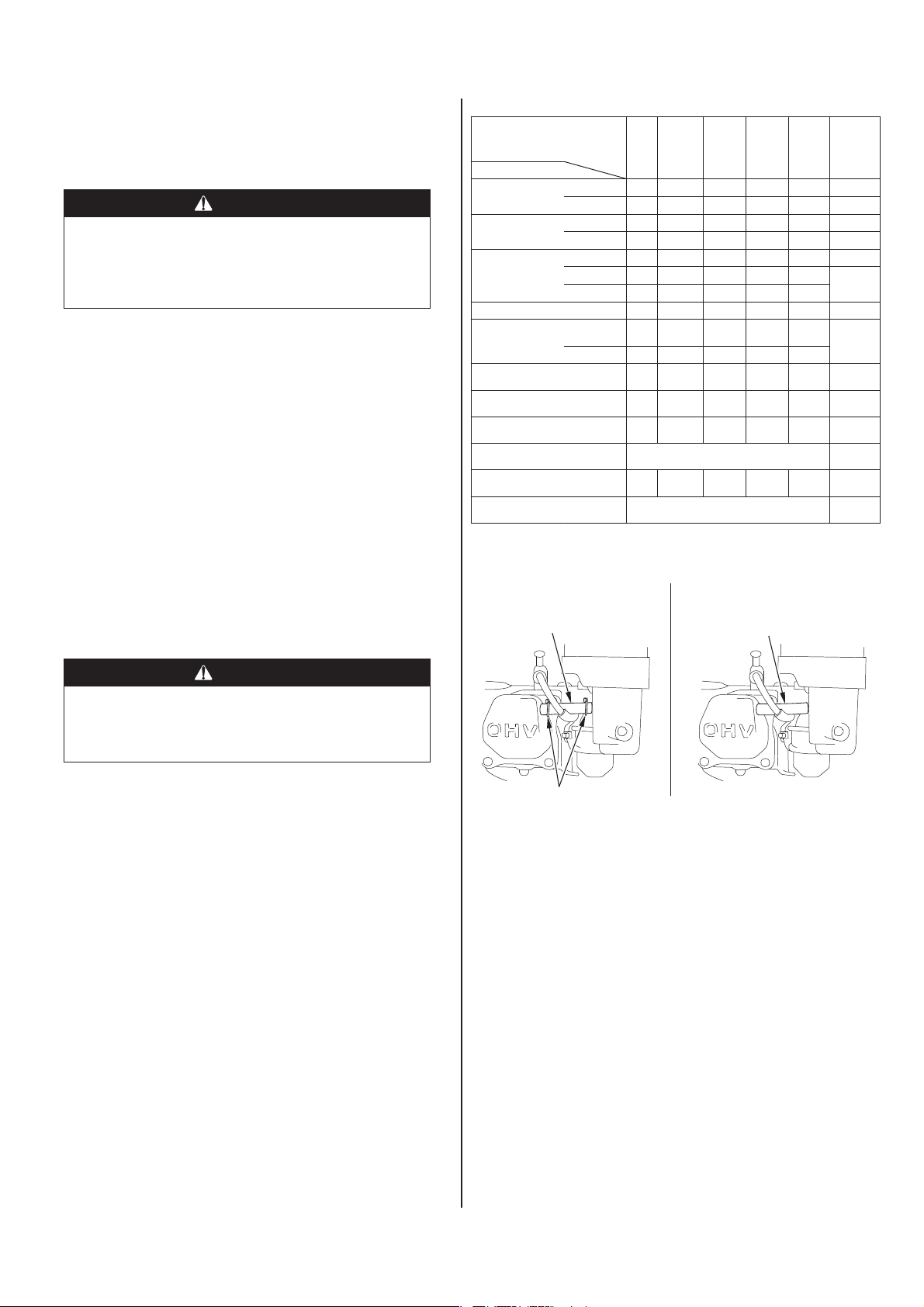
• Endast förgasare med intern ventil och dubbla element.
*
• Cyklontyp var 6:e månad eller var 150:e timme.
MED INTERN VENTIL
AVLUFTNINGSRÖR AVLUFTNINGSRÖR
Kontrollera nivå O 9
Byte O O 9
Kontrollera nivå O 9-10
Byte O O 10
Kontrollera O 10
Rengör O (1)
Byt ut
KontrolleraJustera
Byt ut O
Kontrollera O (4) 13
KontrolleraJustera
KontrolleraJustera
Varje
gång
Första
månaden
eller efter
20 timmar
Var tredje
månad
eller var
50:e
timme
Vartannat år
(Byte vid behov) (2)
STANDARDTYPMODELL MED FÖRGASARE
Var sjätte
månad
eller var
100:e
timme
(1)
O
*
O
Varje år
eller var
300:e
timme
O
* *
O (2) 13
O (2)
Se:
sidanDetalj
11-12
12
Verkst.
handbok
Verkst.
handbok
Verkst.
handbok
Verkst.
handbok
VARNING
Att inte följa instruktioner om underhåll kan orsaka att du blir
allvarligt skadad eller dödad.
Följ alltid anvisningar och säkerhetsföreskrifter enligt denna
bruksanvisning.
SÄKERHETSÅTGÄRDER
• Kontrollera att motorn är avstängd innan du påbörjar något
underhållsarbete eller några reparationer. Koppla från tändkabelskon
vid tändstiftet för att undvika oavsiktlig start. Du kan undvika många
potentiella risker så här:
— Koloxidförgiftning från avgaserna.
Använd bara motorn utomhus, på avstånd från fönster och dörrar.
— Brännskador av uppvärmda delar.
Låt motorn och avgassystemet svalna innan du rör vid dem.
— Skada från rörliga delar.
Kör inte motorn innan du fått anvisningar om att göra detta.
• Läs anvisningarna innan du börjar och se till att du har de verktyg och
färdigheter som krävs.
• Var försiktig när du arbetar i närheten av bensin för att minska risken
för brand eller explosion. Använda bara lösningsmedel som inte är
brandfarliga, inte bensin när du rengör delar. Cigarretter, gnistor och
eld måste hållas på behörigt avstånd från alla bränslerelaterade delar.
Kom ihåg att en auktoriserad Honda-återförsäljare kan din motor bäst
och har rätt utrustning för att serva och reparera den. För att vara
säker på bästa kvalitet och funktion bör du bara använda nya Honda
originalreservdelar eller motsvarande vid reparation och service.
SLANGKLÄMMA
• Byt endast papperselementtyp.
**
• Cyklontyp vartannat år eller var 600:e timme.
(1) Utför service oftare vid användning i dammiga miljöer.
(2) Service på dessa delar ska utföras av serviceverkstad såvida
du inte har rätt verktyg och själv har de mekaniska kunskaper
som krävs. Se Hondas verkstadshandbok för uppgifter om
serviceförfaranden.
(3) Vid kommersiell användning, ska du logga antalet driftstimmar för
att fastställa rätt underhållsintervall.
(4) I Europa och andra länder där maskindirektivet 2006/42/EC gäller,
ska den här rengöringen utföras av återförsäljaren.
Om underhållsschemat inte följs kan detta leda till fel som inte täcks
av garantin.
SVENSKA 7
Page 32

BRÄNSLEPÅFYLLNING
Rekommenderat bränsle
Blyfri bensin
USA Pumpbensin, oktantal på 86 eller högre
Utanför
USA
Bensin med oktantal på 91 eller högre
Pumpbensin, oktantal på 86 eller högre
Denna motor är godkänd för att köras på blyfri bensin med ett oktantal
på 86 eller högre (oktantal på 91 eller högre).
Fyll på bränsle i ett väl ventilerat utrymme med motorn avstängd. Låt
motorn svalna först om den varit igång. Fyll aldrig på bränsle inomhus
där bensinångorna kan komma i kontakt med flammor eller gnistor.
Man kan använda blyfri bensin som inte innehåller mer än 10
volymprocent etanol (E10) eller 5 volymprocent metanol. Dessutom
ska metanolen innehålla lösningsmedel och korrosionsskyddsmedel.
Användning av ett bränsle som innehåller mer etanol eller metanol än
vad som visas ovan kan leda till problem när det gäller start och/eller
prestanda. Det kan också skada delar i metall, gummi och plast som
ingår i bränslesystemet. Motorskador eller driftsproblem på grund av
att man använder bränsle med procentuellt större mängd etanol eller
metanol i än vad som visas här ovan, täcks inte av garantin.
Om utrustningen ska användas sällan eller oregelbundet bör du läsa
bränsleavsnittet i kapitlet FÖRVARING AV MOTORN (se sidan 13) för
ytterligare information om bränslenedbrytning.
Använd aldrig gammal eller förorenad bensin eller oljeblandad bensin.
Se till att smuts och vatten inte kan komma in i bränsletanken.
VARNING
Bensin är mycket brandfarligt och explosivt och kan
orsaka brännskador eller allvarliga personskador vid
bränslepåfyllning.
• Stanna motorn och undvik gnistor, värme och öppen låga.
• Fyll endast på bränsle utomhus.
• Torka upp spill omedelbart.
Fyll på försiktigt så att du inte spiller ut bränsle. Fyll inte tanken helt.
Det kan var nödvändigt att ha mindre bensin i tanken beroende på
driftsförhållandena. Efter tankning skruvar du på locket tills ett klick hörs.
Håll bensin på behörigt avstånd från tändsystem, grillar, elutrustning,
motordrivna verktyg etc.
Utspillt bränsle är inte bara brandfarligt utan även miljöfarligt. Torka upp
spill omedelbart.
MOTOROLJA
Oljan är en viktig komponent som påverkar prestanda och livslängd.
Använd fyrtaktsolja av biltyp.
Rekommenderad olja
Använd en fyrtaktsolja som uppfyller eller överskrider kraven för API,
servicekategori SJ eller senare (eller motsvarande). Kontrollera alltid
API-serviceskylten på oljebehållaren för att försäkra dig om att den har
bokstäverna SJ eller senars (eller motsvarande).
OMGIVNINGSTEMPERATUR
SAE 10W-30 rekommenderas för allmän användning. Andra viskositeter
i schemat kan användas när medeltemperaturen i ditt körområde är
inom angivna intervaller.
OBS!
Bränsle kan skada lacker och vissa typer av plast. Var försiktig så att
du inte spiller ut bränsle när du fyller på tanken. Skador som orakats
av utspillt bränsle täcks inte av Leverantörens begränsade garanti.
Flytta dig minst 1 meter från bränslekällan och platsen innan du
startar motorn.
1. Motorn ska vara stoppad och på ett jämns underlag när man tar
av tanklocket för att kontrollera bränslenivån. Fyll på tanken om
bränslenivån är låg.
2. Fyll på bränsle till precis under gränslinjen i bränsletanken. Fyll inte
på för mycket. Torka upp utspillt bränsle innan du startar motorn.
TANKLOCK
MAX.
BRÄNSLENIVÅ
8 SVENSKA
Page 33

Kontroll av oljenivå
Kontrollera motoroljenivån med motorn avstängd och på plant underlag.
1. Ta bort oljepåfyllningslocket/oljestickan och torka av.
2. Sätt in oljepåfyllningslocket/oljestickan så som figuren visar men
skruva inte in. Ta sedan ut oljestickan igen och kontrollera nivån.
3. Om oljenivån är nära eller under den nedre gränsmarkeringen på
oljestickan – fyll på med rekommenderad olja (se sidan 8) till det
övre gränsvärdet (nedre kanten på oljepåfyllningshålet). Fyll inte
på för mycket.
4. Sätt tillbaka oljepåfyllningslocket/oljestickan.
4. Montera oljepåfyllningslocket/oljestickan och dra åt ordentligt.
BRICKA
TÖMNINGSPLUGG
OLJEPÅFYLLNINGSLOCK/
OLJESTICKA
OLJENIVÅ
OLJEPÅFYLLNINGSLOCK/OLJESTICKA
OLJEPÅFYLLNINGSHÅL
(nedre kant)
ÖVRE GRÄNS
NEDRE GRÄNS
OBS!
Om motorn körs med låg oljenivå kan motorskador uppstå. Denna typ
av skada täcks inte av Leverantörens begränsade garanti.
Oil Alert-systemet (vissa modeller) stannar motorn automatiskt innan
oljenivån går under säkerhetsnivån. Men för att slippa besvär med en
plötslig avstängning, ska man alltid kontrollera motoroljenivån innan
man startar motorn.
Oljebyte
Töm ut den gamla oljan när motorn är varm. Varm olja rinner ut snabbt
och fullständigt.
1. Ställ en behållare under motorn för den gamla oljan. Ta sedan bort
oljepåfyllningslocket/oljestickan, oljepluggen och brickan.
2. Låt den gamla oljan rinna ut helt och hållet, och sätt sedan tillbaka
oljepluggen och en ny bricka. Dra åt oljepluggen ordentligt.
Ta hand om gammal motorolja på ett godkänt och miljövänligt
sätt. Ta med den använda oljan i en stängd behållare till en
återvinningsstation eller verkstad för återvinning. Den får inte kastas
i soporna, hällas ut på marken eller hällas ut i avloppet.
3. Ställ motorn på plant underlag, fyll på med rekommenderad olja
(se sidan 8) upp till övre gränsvärdet på oljestickan (nedre kanten
på oljepåfyllningshålet).
OBS!
Om motorn körs med låg oljenivå kan motorskador uppstå. Denna
typ av skada täcks inte av Leverantörens begränsade garanti.
Oil Alert-systemet (vissa modeller) stannar motorn automatiskt innan
oljenivån går under säkerhetsnivån. Fyll på till övre gränsen och
kontrollera oljan regelbundet för att undvika oavsiktlig avstängning.
Tvätta händerna med tvål och vatten efter att du har handskats med
smutsig olja.
SLUTVÄXELOLJA (vissa modeller)
Rekommenderad olja
Använd samma olja som rekommenderas för motorn (se sidan 8).
Kontroll av oljenivå
Kontrollera slutväxelns oljenivå med motorn avstängd och på plant underlag.
2 : 1 Slutväxel med centrifugalkoppling
1. Ta bort oljepåfyllningslocket/oljestickan och torka av.
2. Sätt in och ta ut oljepåfyllningslocket/oljestickan utan att skruva
in i påfyllningshålet. Kontrollera oljenivån på oljepåfyllningslocket/
oljestickan.
3. Fyll på olja till det övre gränsvärdet på oljestickan. Använd
rekommenderad olja.
4. Skruva in oljepåfyllningslocket/oljestickan och dra åt ordentligt.
PÅFYLLNINGSLOCK/
ÖVRE
GRÄNS
NEDRE GRÄNS
OLJESTICKA
SVENSKA 9
Page 34

6 : 1 Slutväxelhus
1. Ta bort oljenivåskruven och
OLJENIVÅ
PÅFYLLNINGSBULT
brickan, och se om oljan når upp till
skruvhålets kant.
2. Om oljenivån är under skruvhålets
nivå – ta bort påfyllningsskruven och
brickan. Fyll på olja tills oljan börjar
rinna ut genom kontrollskruvhålet.
Använd rekommenderad olja
(se sidan 9).
3. Sätt tillbaka oljekontrollskruv,
påfyllningsskruv och brickor. Dra åt
dem säkert.
Oljebyte
SKRUV FÖR KONTROLL AV OLJENIVÅ
2 : 1 Slutväxel med centrifugalkoppling
Töm ut den gamla oljan när motorn är varm. Varm olja rinner ut snabbt
och fullständigt.
1. Ställ en behållare under slutväxelhuset för den gamla oljan. Ta sedan
bort oljepåfyllningslocket/oljestickan, tömningspluggen och brickan.
2. Låt den gamla oljan rinna ut helt och hållet, och sätt sedan tillbaka
oljepluggen och en ny bricka. Dra åt oljepluggen ordentligt.
Ta hand om gammal motorolja på ett godkänt och miljövänligt
sätt. Ta med den använda oljan i en stängd behållare till en
återvinningsstation eller verkstad för återvinning. Den får inte kastas i
soporna, hällas ut på marken eller hällas ut i avloppet.
3. Ställ motorn på plant underlag, fyll på upp till övre gränsvärdet på
oljestickan. Använd rekommenderad olja (se sidan 9). Kontrollera
oljenivån genom att sätta in och ta ut oljestickan utan att skruva in den.
Oljekapacitet i slutväxelhuset: 0,5 liter
OBS!
Om motorn körs med för lite olja i slutväxelhuset kan motorskador
uppstå.
4. Skruva in oljepåfyllningslocket/oljestickan säkert.
Tvätta händerna med tvål och vatten efter att du har handskats med
smutsig olja.
PÅFYLLNINGSLOCK/
OLJESTICKA
ÖVRE
GRÄNS
NEDRE GRÄNS
TÖMNINGSPLUGG
6 : 1 Slutväxelhus
Töm ut den gamla oljan när motorn är varm. Varm olja rinner ut snabbt
och fullständigt.
1. Ställ en behållare under slutväxelhuset för den gamla oljan. Ta sedan
bort påfyllningslocket/oljestickan, oljenivåskruven och brickorna.
2. Töm ut den gamla oljan helt och hållet i en behållare genom att tippa
motorn mot oljekontrollhålet.
Ta hand om gammal motorolja på ett godkänt och miljövänligt
sätt. Ta med den använda oljan i en stängd behållare till en
återvinningsstation eller verkstad för återvinning. Den får inte kastas
i soporna, hällas ut på marken eller hällas ut i avloppet.
3. Ställ motorn plant. Fyll på olja tills oljan börjar rinna ut genom
kontrollskruvens hål. Använd rekommenderad olja (se sidan 9).
OBS!
Om motorn körs med för lite olja i slutväxelhuset kan motorskador
uppstå.
4. Sätt tillbaka oljekontrollskruv, påfyllningsskruv och brickor. Dra åt
ordentligt.
PÅFYLLNINGSBULT
OLJENIVÅ
SKRUV FÖR KONTROLL AV OLJENIVÅ
Tvätta händerna med tvål och vatten efter att du har handskats med
smutsig olja.
LUFTRENARE
En smutsig luftrenare begränsar luftflödet till förgasaren och försämrar
motorns prestanda. Om motorn körs på mycket dammiga platser måste
luftfiltret rengöras oftare än vad som anges i underhållsschemat.
OBS!
Om man använder motorn utan luftfilter, eller med ett skadat luftfilter,
kan det komma in smuts i motorn, vilket snabbt ger skador på den.
Denna typ av skada täcks inte av Leverantörens begränsade garanti.
Kontroll
Ta bort luftrenarkåpan och kontrollera filterelementen. Rengör eller byt
ut smutsiga filterelement. Byt alltid ut skadade filterelement. Kontrollera
även oljenivån om utrustningen har luftrenare av oljetyp.
Se sidorna 11 – 12 för anvisningar som gäller luftrenare och filter för
aktuell motortyp.
10 SVENSKA
Page 35

Rengöring
Dubbelfilter
1. Ta bort vingmuttern från
luftrenarkåpan och ta bort
kåpan.
2. Ta bort vingmuttern från
luftfiltret och ta bort filtret.
3. Ta bort skumplastfiltret
från pappersfiltret.
4. Kontrollera båda
luftfilterelementen
och byt ut dem om de
skadats. Sätt alltid tillbaka
luftfiltrets papperselement
vid angivna intervall
(se sidan 7).
DUBBELT FILTERELEMENT (CYKLON)
KONISK
SKRUV (3)
SPÅR
LUFTSTYRNING
DUBBELFILTER (STANDARD)
VINGMUTTER
LUFTRENARENS
KÅPA
VINGMUTTER
PAPPERSFILTERELEMENT
SKUMPLASTFILTERELEMENT
PACKNING
VINGMUTTERFÖRRENARKÅPA
LUFTRENARENS KÅPA
VINGMUTTER
PAPPERSFILTERELEMENT
SKUMPLASTFILTERELEMENT
7. Torka av smutsen från luftrenarens insida (basdel och kåpa) med en
fuktig trasa. Var försiktig så att inte smuts kommer in i luftkanalen
som går till förgasaren.
8. Placera luftfilterelementet av skumplast över papperselementet och
sätt tillbaka det hopmonterade luftfiltret. Kontrollera att packningen
sitter som den ska under luftfiltret. Dra åt luftfiltrets vingmutter så den
sitter ordentligt.
9. Montera luftrenarkåpan och dra åt kåpans vingmutter ordentligt.
Oljebadtyp
1. Ta bort vingmuttern och ta bort luftrenarlocket och kåpan.
2. Ta bort luftfilterelementet. Tvätta kåpan och filterelement i varmt
löddrande vatten, skölj och låt torka ordentligt. Eller rengör med ett
lösningsmedel, som inte är brandfarligt, och låt torka ordentligt.
3. Doppa filterelementet i ren motorolja och krama sedan ut all
överflödig olja. Motorn ryker om det är för mycket olja kvar i
skumplasten.
4. Töm ut den gamla oljan ur luftrenarhuset, tvätta bort smuts med
rengöringsmedel (ej brandfarligt!) och torka av.
5. Fyll luftrenarhuset till märket OIL LEVEL (oljenivå) med samma olja
som rekommenderas för motorn (se sidan 8).
3
Oljevolym: 60 cm
6. Montera luftrenaren och dra åt vingmuttern ordentligt.
LUFTRENARENS KÅPA
LUFTFILTERELEMENT
VINGMUTTER
LOCK
KLACK
PACKNING
CYKLONHUS
5. Rengör luftfilterelementen om de ska återanvändas.
Pappersfilterselement: Knacka filterelementet flera gånger mot
en hård yta för att avlägsna smuts eller blåsa tryckluft [som inte
överstiger 207 kPa (2,1 kgf/cm²)] genom filtret från insidan. Försök
aldrig borsta av smuts; borstning driver in smuts i fibrerna.
Skumplastfilterselement: Rengör med varmt tvålvatten, skölj och
låt torka ordentligt. Eller rengör med ett lösningsmedel, som inte är
brandfarligt, och låt torka ordentligt. Doppa filtret i ren motorolja och
krama sedan ut all överflödig olja. Motorn ryker när man startar den
om det är för mycket olja kvar i skumplasten.
6. ENDAST CYKLONTYP: Ta bort de tre skruvarna (koniskt huvud) från
förrenarkåpan, och därefter cyklonhuset och luftstyrningen. Tvätta
delarna med vatten, torka dem noggrant och montera ihop dem igen.
Montera luftstyrningen så som figuren visar.
Montera cyklonhuset så att luftintagets klack passar i spåret i insatsen.
NÄT
LUFTRENARHUS
OLJENIVÅ
SVENSKA 11
Page 36

Typ med låg profil
1. Knäpp upp luftrenarkåpans
KLÄMMA LUFTRENARENS KÅPA
klämmor, ta bort
luftrenarkåpan och ta bort
luftfilterelementet.
2. Tvätta elementet i en
lösning bestående av
hushållsrengöringsmedel
och varmt vatten och skölj
sedan ordentligt. Eller
tvätta i icke brandfarligt
lösningsmedel eller
lösningsmedel med hög
flampunkt. Låt elementet
LUFTFILTERELEMENT
KLÄMMA
torka ordentligt.
3. Sänk ner luftfilterelementet
i ren motorolja och pressa
sedan ut överskottsoljan.
Om det är för mycket olja
kvar i elementet ryker
motorn när den startas
första gången.
4. Sätt tillbaka
luftfilterelementet och
kåpan.
LUFTFILTERELEMENT
SLAMUPPSAMLINGSSKÅL
Rengöring
VARNING
Bensin är mycket brandfarligt och explosivt och kan orsaka
brännskador eller allvarliga personskador vid hantering av
bränsle.
• Stanna motorn och undvik gnistor, värme och öppen låga.
• Fyll endast på bränsle utomhus.
• Torka upp spill omedelbart.
1. Sätt bränslekranen i läge OFF (AV) och ta sedan bort
slamuppsamlingsskålen och O-ringen.
2. Tvätta slamuppsamlingsskålen och O-ringen i rengöringsmedel som
INTE är brandfarligt, och torka ordentligt.
FILTER
(sett underifrån)
4. Flytta bränsleventilen till läge ON (PÅ) och kontrollera om det finns
läckage. Byt ut O-ringen om det finns några läckage.
TÄNDSTIFT
Rekommenderade tändstift: BPR6ES (NGK)
W20EPR-U (DENSO)
Det rekommenderade tändstiftet har korrekt värmetal för normala
drifttemperaturer för motorn.
OBS!
Felaktiga tändstift kan orsaka motorskador.
För bästa prestanda måste tändstiftet ha rätt elektrodavstånd och vara
fritt från avlagringar.
TÄNDSTIFTSNYCKEL
1. Tag bort tändkabelskon och
ta bort all smuts runtom
tändstiftet.
2. Ta bort tändstiftet med en
tändstiftsnyckel (13/16 tum).
3. Kontrollera tändstiftet. Byt
tändstiftet om det är skadat
eller kraftigt nedsmutsat, om
tätningsbrickan är dålig eller
om elektroden är sliten.
4. Mät elektrodavståndet med ett
bladmått. Korrigera vid behov
genom att böja sidoelektroden
SIDOELEKTROD
0,7 -0,8 mm
försiktigt. Elektrodavståndet
ska vara:
0,7-0,8 mm
5. Montera tändstiftet försiktigt
TÄTNINGSBRICKA
(för hand) så att inte gängorna
skadas.
6. Dra in stiftet till anliggning
mot packningen och dra
sedan åt med en 13/16-tums
tändstiftsnyckel för att pressa samman packningen.
Ett nytt tändstift ska dras åt 1/2 varv efter anliggning för att brickan ska
tryckas samman.
Ett tändstift som återanvänds ska dras 1/8-1/4 varv efter anliggning för
att pressa samman brickan.
OBS!
Ett löst sittande tändstift kan överhetta motorn och skada den. Alltför
kraftig åtdragning av tändstiftet kan skada gängorna i topplocket.
7. Fäst tändkabelskon vid tändstiftet.
OFF (AV)
BRÄNSLEVENTILARM
Passa in
FILTER
O-RING
SLAMUPPSAMLINGSSKÅL
3. Montera filtret och placera O-ringen i bränslekranen och montera
slamuppsamlingsskålen. Dra åt slamuppsamlingsskålen ordentligt.
12 SVENSKA
Page 37

GNISTSLÄCKARE (vissa modeller)
I Europa och andra länder där maskindirektivet 2006/42/EC gäller, ska
den här rengöringen utföras av återförsäljaren.
Gnistsläckaren kan vara standardutrustning eller tillval beroende på
motormodell. I vissa regioner är det olagligt att köra en motor utan
gnistsläckare. Kontrollera lokala lagar och bestämmelser. Gnistsläckare
kan beställas från auktoriserade Honda-serviceverkstäder.
Man måste utföra service på gnistsläckaren var 100:e timma för att den
ska fungera på avsett sätt.
Om motorn har varit i gång är ljuddämparen het. Låt den svalna innan
servicearbete utförs på den.
Borttagning av gnistsläckare
1. Ta bort luftrenaren (sidan 11).
2. Lossa de två 4-mmskruvarna från ljuddämparavledaren och demontera
sedan avledaren och ljuddämparens styrning (vissa modeller).
3. Lossa de fyra 5-mmskruvarna från ljuddämparskyddet och ta
bort skyddet.
4. Lossa skruven på 4 mm från gnistsläckaren och ta bort
gnistsläckaren från ljuddämparen.
SKRUVAR PÅ 5 mm
LJUDDÄMPARSKYDD
LJUDDÄMPARAVLEDARE
AVGASAVLEDARE
SKRUVAR PÅ
4 mm
SKRUV PÅ 4 mm
GNISTSLÄCKARE
Rengöring och kontroll av gnistsläckare
1. Använd en borste för att ta bort
sotavlagringar från gnistsläckarens nät.
Var försiktig så att nätet inte skadas. Byt
gnistsläckaren om den har hål eller skador.
SKÄRM
2. Montera gnistsläckaren, ljuddämparskyddet, ljuddämparavledaren
och ljuddämparen i motsatt ordning mot demonteringen.
3. Montera luftrenaren (se sidan 11).
TOMGÅNGSVARVTAL
STOPPSKRUV FÖR GASSPJÄLL
Justering
1. Starta motorn utomhus
och låt den värmas upp till
drifttemperaturen.
2. Flytta gasreglaget till
minimiläget.
3. Vrid gasspjällets stoppskruv för
att ställa in rätt tomgångsvarvtal.
+200 Normalt tomgångsvarvtal:
1,400 -150
(varv/min)
TIPS OCH FÖRSLAG
FÖRV ARING AV MOTORN
Förberedelser före förvaring
Korrekt förvaring är mycket viktigt för att motorn ska fungera problemfritt
och se bra ut. Följande steg hjälper till att hindra rost och korrosion från
att försämra motorns funktion och utseende. Och motorn går lättare att
starta nästa gång du ska använda den.
Rengöring
Låt motorn svalna under minst en halvtimme före rengöringen om den
har varit igång nyligen. Rengör alla yttre ytor, bättra på färg som skadats
och täck ytor som kan rosta med ett tunt lager olja.
OBS!
Använd inte trädgårdsslang eller högtryckstvätt eftersom dessa
kan pressa in vatten i luftrenaren eller ljuddämparen. Vatten i
luftrenaren dränker luftfiltret, och vatten som går igenom luftfiltret eller
ljuddämparen, kan komma in i cylindern och orsaka skador.
Bränsle
OBS!
Det kan det vara så att, beroende på det område där du använder din
utrustning, bränsleblandningar snabbt kan försämras och oxideras.
Försämring och oxidering av bränsle kan uppstå på endast 30
dagar och detta kan skada förgasaren och/eller bränslesystemet.
Kontakta närmaste serviceverkstad för information om lokala
förvaringsrekommendationer.
Bensin oxideras och bryts ned när den förvaras under lång
tid. Försämrad bensin gör det svårare att starta och det bildas
gummiavlagringar som täpper till bränslesystemet. Om bensinen i din
motor försämras under förvaringen, kan det bli nödvändigt att byta ut
eller serva förgasaren och andra bränslesystemskomponenter.
Den tid som bränslet kan förvaras i bränsletanken och förgasaren
utan att driftproblem uppstår varierar utifrån sådana faktorer som
bränsleblandning, förvaringstemperatur och om bränsletanken är helt
eller delvis fylld. Luften i en delvis fylld bränsletank gör att bränslet
försämras snabbare. Väldigt varma förvaringstemperaturer gör att
bränsleförsämringen går snabbare. Bränslenedbrytning kan uppstå
inom några månader, eller ännu kortare tid, om bensinen var gammal
när du fyllde på bränsletanken.
Skador i bränslesystemet eller prestandaproblem som ett resultat av
felaktig förvaring täcks inte av Leverantörens begränsade garanti.
Du kan förlänga bränslets livslängd genom att tillsätta ett
stabiliseringsmedel, eller undvika att bränslet bryts ner genom att
tömma bränsletanken och förgasaren.
Fylla på med stabiliseringsmedel för att förlänga bränslets
livslängd
När man fyller på stabiliseringsmedel i bränslet ska bränsletanken först
fyllas med ny bensin. Om den bara är delvis fylld kommer luften i tanken
att snabba upp bränslenedbrytningen under förvaringen. Om du har en
behållare med påfyllningsbensin, ska du se till att den endast innehåller
ny bensin.
1. Fyll på stabiliseringsmedel enligt tillverkarens anvisningar.
2. När du tillsatt stabiliseringsmedel, ska du låta motorn gå i tio minuter
för att vara säker på att bensinen har ersatt den obehandlade
bensinen i förgasaren.
3. Stäng av motorn.
SVENSKA 13
Page 38

Tömning av bränsletank och förgasare
VARNING
Bensin är mycket brandfarligt och explosivt och kan orsaka
brännskador eller allvarliga personskador vid hantering av
bränsle.
• Stanna motorn och undvik gnistor, värme och öppen låga.
• Bränsle ska bara hanteras utomhus.
• Torka upp spill omedelbart.
1. Flytta bränslekranen till läge OFF (AV) (se sidan 6).
2. Sätt en godkänd bensindunk under förgasaren och använd en tratt
så att inget bränsle spills ut.
3. Ta bort förgasarens tömningsskruv och packning. Ta bort
slamuppsamlingsskålen och O-ringen och flytta sedan bensinkranen
till läge ON (PÅ) (se sidan 4).
BRÄNSLEVENTILARM
O-RING
SLAMUPPSAMLINGSSKÅL
PACKNING
FÖRGASARENS
TÖMNINGSSKRUV
ON (PÅ)
Förebyggande åtgärder före förvaring
Om motorn ska förvaras med bensin i bränsletanken och förgasaren,
är det viktigt att förebygga risken för antändning av bensinångor. Välj
ett välventilerat förvaringsutrymme som ligger på behörigt avstånd från
utrustning med öppen låga, som till exempel en eldstad, vattenvärmare
eller klädtorkare. Undvik alla platser där det förekommer gnistor
(elmotorer) eller där motordrivna verktyg används.
Om möjligt, ska man även undvika förvaringsutrymmen med hög
luftfuktighet, eftersom det kan leda till rost och korrosion.
Ställ motorn plant vid förvaring. Lutning kan orsaka bränsle- eller
oljeläckage.
Kontrollera att motorn och avgassystemet är svala och täck över motorn
för att hålla dammet borta. En het motor och ett hett avgassystem kan
antända eller smälta vissa material. Använd inte plastskynken som
dammöverdrag. Ett helt tätt överdrag gör att fukt hålls kvar runt motorn,
vilket underlättar för rost och korrosion.
Ett batteri för elstart ska laddas upp en gång i månaden under motorns
förvaring. Detta hjälper till att förlänga batteriets livslängd.
När maskinen ska användas igen efter förvaring
Kontrollera motor enligt beskrivningen i avsnittet KONTROLLER FÖRE
ANVÄNDNING i den här bruksanvisningen (se sidan 4).
Om bränslet tömdes ut innan maskinen ställdes undan ska tanken fyllas
med ny bensin. Om du har en reservdunk ska du tillse att den bara
innehåller ny bensin. Bensin oxideras och bryts ner med tiden vilket gör
att maskinen blir svårare att starta.
Om cylindern bestrukits med olja innan maskinen ställdes undan
kommer motorn att ryka något vid starten. Detta är normalt.
4. När allt bränsle samlats upp sätter du tillbaka tömningsskruven,
packningen, slamuppsamlingsskålen och O-ringen. Dra åt
tömningsskruven och fäst slamuppsamlingsskålen säkert.
Motorolja
1. Byt motorolja (se sidan 9).
2. Ta bort tändstiftet (se sidan 12).
3. Häll i en tesked med 5-10 cm³ (5-10 cc) ren motorolja i cylindern.
4. Dra i startsnöret flera gånger så att oljan fördelas i cylindern.
5. Sätt tillbaka tändstiftet.
6. Drag sakta i startsnöret tills det känns ett motstånd. Fortsätt
att dra tills strecket på startsnörskivan står mitt för hålet i
snörstartmekanismen. I detta läge är ventilerna stängda och ingen
fukt kan komma in i cylindern. Släpp tillbaka startsnöret försiktigt.
Rikta in märket på skivan med
hålet överst på kåpan.
TRANSPORT
Om motorn varit på, ska den svalna i minst 15 minuter innan man lastar på
utrustningen som drivs av motorn på transportfordonet. En het motor och
ett hett avgassystem kan orsaka brännskador eller smälta vissa material.
Ställ motorn plant under transport för att minska risken för
bränsleläckage. Flytta bränslekranen till läge OFF (AV) (se sidan 6).
7. Elektrisk start: Ta bort batteriet och förvara det på en sval och torr
plats. Ladda det en gång i månaden.
8. Täck över motorn för att skydda mot damm.
14 SVENSKA
Page 39

HANTERING AV OVÄNTADE PROBLEM
MOTORN STARTAR INTE Möjlig orsak Korrigering
1. Elstart (vissa modeller):
Kontrollera batteri och
säkring.
2. Kontrollera
kontrollpunkter.
3. Kontrollera
motoroljenivån.
4. Kontrollera bränslet. Slut på bränsle. Fyll på bränsle
5. Ta ur och inspektera
tändstiftet.
6. Ta motorn till
en auktoriserad
Hondaverkstad eller se
verkstadshandboken.
Batteriet urladdat. Ladda batteriet.
Säkring bränd. Byt säkring (sid 15).
Bränslekran
OFF (AV).
Choke öppen. Flytta reglaget
Motorns stoppknapp
är i OFF (AV)-läget.
Låg motoroljenivå
(Oil Alert-modeller).
Dåligt bränsle; motorn
har förvarats utan att
bränslet behandlats,
bränslet har tömts
ut, dåligt bränsle har
fyllts på.
Tändstiftet felaktigt,
smutsigt eller fel
elektrodavstånd.
Tändstiftet dränkt
av bränsle (flödad
motor).
Bränslefiltret igensatt,
fel på förgasaren,
fel på tändningen,
ventiler har fastnat
etc.
Flytta reglaget till
läget ON (PÅ).
till stängt läge
(CLOSED) tills motorn
är varm.
Vrid
motoromkopplaren till
läget ON (PÅ).
Fyll på med
rekommenderad olja
till rätt nivå (sidan 9).
(sidan 8).
Tappa av
bränsletanken och
förgasaren (sidan 14).
Fyll på med ny bensin
(sidan 8).
Justera
elektrodavståndet
eller byt tändstift
(sidan 12).
Torka av tändstiftet
och sätt tillbaka det.
Starta motorn med
gasreglaget i MAXläge.
Byt ut eller
reparera felaktiga
komponenter.
BYTE AV SÄKRING (vissa modeller)
Elstartens reläkrets och batteriets laddningskrets skyddas av en säkring.
Om säkringen går, fungerar inte elstarten. Motorn kan startas manuellt
om säkringen bränt, men batteriet laddas då inte när motorn är igång.
1. Lossa de 6 x 12 mm specialskruvarna från den bakre kåpan på
motorns kopplingsdosa och ta bort den bakre kåpan.
2. Ta bort locket över säkringen och dra sedan ut säkringen och
kontrollera den.
Kassera säkringen om den är bränd. Sätt i en ny säkring med
samma styrka som den som togs bort och sätt tillbaka kåpan.
Om du har frågor om originalsäkringens styrka, kontakta din Honda-
återförsäljare.
OBS!
Använd aldrig en säkring med högre styrka än originalsäkringen
som levererades med motorn. Detta kan orsaka brand eller allvarliga
skador på elsystemet.
3. Sätt tillbaka det bakre höljet. Sätt tillbaka 6 ×12 mm-skruven och dra
åt den ordentligt.
MOTOROMKOPPLARE,
SÄKRING
KÅPA
SÄKRING
BAKRE KÅPA
SPECIALSKRUV på 6 X 12 mm
MOTORN SAKNAR
KRAFT
1. Kontrollera luftfiltret. Filterelement
2. Kontrollera bränslet. Dåligt bränsle; motorn
3. Ta motorn till
en auktoriserad
Hondaverkstad eller se
verkstadshandboken.
Möjlig orsak Korrigering
tilltäppt(a).
har förvarats utan att
bränslet behandlats,
bränslet har tömts
ut, dåligt bränsle har
fyllts på.
Bränslefiltret igensatt,
fel på förgasaren,
fel på tändningen,
ventiler har fastnat
etc.
Rengör eller byt ut
filterelementen (sidan
11-12).
Tappa av
bränsletanken och
förgasaren (sidan 14).
Fyll på med ny bensin
(sidan 8).
Byt ut eller
reparera felaktiga
komponenter.
Om säkringen bränner ofta tyder det på kortslutning eller överbelastning
i elsystemet. Om säkringen går ofta, ska du ta motorn till en Hondaverkstad för reparation.
SVENSKA 15
Page 40

TEKNISK INFORMATION
Serienumrets placering
Skriv upp motorns serienummer,
typ och inköpsdatum i utrymmet
nedan. Denna information
behövs när du beställer
delar och när du gör tekniska
garantianspråk.
Länksystem för fjärrkontroll
Gasreglaget och chokereglaget har hål för extra vajrar. Följande
illustrationer visar monteringsexempel för en solid vajer och för en
flexibel, flätad vajer. Vid användning av flexibel flätad vajer ska en
returfjäder läggas till enligt figuren.
Man måste lossa gasreglagets friktionsmutter när gasreglaget ska
fjärrmanövreras.
LÄNKSYSTEM FÖR FJÄRRMANÖVRERING AV GASREGLAGE
ELSTART (vissa modeller)
SERIENUMRETS OCH
MOTORTYPENS PLATS
Motorns serienummer: _ _ _ _ _ _ _ _ - _ _ _ _ _ _ _ _ _ _ _ _ _ _
Motortyp: ___ ___ ___ ___
Inköpsdatum: ______ / ______ / ______
Batterianslutningar för elstart (vissa modeller)
Använd ett batteri på 12 V med en kapacitet av minst 18 Ah.
Var försiktig så att du inte ansluter ett batteri till den motsatta polen,
eftersom det kommer att kortsluta batteriets laddningssystem. Anslut
alltid batteriets pluspol (+) till batterianslutningen innan du ansluter
minuskabeln (–), så att verktygen inte kan orsaka kortslutning om de
kommer i kontakt med en jordad del när man drar åt pluspolens (+)
batterikabel.
VARNING
Ett batteri kan explodera om man inte följer rätt arbetsgång
vilket kan orsaka allvarliga personskador.
Håll gnistor, öppna lågor och rökvaror borta från batteriet.
VARNING: Batteriet, dess poler och tillbehör innehåller bly och
blysammansättningar. Tvätta händerna efter hantering.
1. Anslut batteriets pluspol (+) till startreläets anslutning som bilden visar.
2. Anslut batteriets minuskabel (–) till en av motorns fästbultar, rambult
eller annan jordad anslutning för motorn.
3. Anslut batteriets pluskabel (+) till batteriets pluspol (+) som bilden visar.
4. Anslut batteriets minuskabel (–) till batteriets minuspol (–) som
bilden visar.
5. Smörj in polerna och kabeländarna med fett.
FRIKTIONSMUTTER FÖR
GASREGLAGE
Flexibel ledarkärna
(montering)
SKRUV PÅ 4 mm
VAJERHÅLLARE
GAS
ARM
Fast ledarkärna
(montering)
VAJER
FJÄDERBRICKA
5 mm
LÄNKSYSTEM FÖR FJÄRRMANÖVRERING AV CHOKE
VAJERHÅLLARE
CHOKEREGLAGE
RETURFJÄDER
TILLVAL
NEGATIV (-)
BATTERIKABEL
POSITIV (+) BATTERIKABEL
STARTMOTORNS
MAGNETVENTIL
16 SVENSKA
Page 41

Modifiering av förgasare för körning på hög höjd
På hög höjd är den vanliga luft-/bränsleblandningen för rik för
förgasaren. Motorns prestanda minskar och bränsleförbrukningen
ökar. En mycket fet blandning smutsar också ner tändstiftet och gör det
svårare att starta. Drift på högre höjder än motorn är avsedd för under
längre tidsperioder, kan öka avgasutsläppen.
Motorns prestanda på höga höjder kan förbättras genom särskilda
modifieringar av förgasaren. Om motorn alltid ska köras på höjder över
1 500 meter över havet ska serviceverkstaden modifiera förgasaren.
När den här motorn körs på hög höjd med modifierad förgasare kommer
den att uppfylla gällande miljöstandarder under hela sin livslängd.
Men med modifieringar i förgasaren kommer motorns hästkraft ända
att minska med 3,5 % för varje höjdökning på 300 meter. Hästkraftens
påverkan av höjdökningen blir ännu större om ingen modifiering görs i
förgasaren.
OBS!
När förgasaren modifierats för användning på hög höjd kommer
bränsle-/luftblandningen att vara för mager för körning på låg höjd.
Drift med en modifierad förgasare på höjder under 1500 meter kan
leda till att motorn överhettas och orsaka allvarliga skador på motorn.
Vid användning på låga höjder ska serviceverkstaden återställa
förgasaren till ursprungsskicket.
Information om system för utsläppskontroll
Utsläppskällor
Förbränningsprocessen producerar koloxid, kväveoxider och kolväten.
Det är därför mycket viktigt att kolväten och kväveoxider begränsas,
eftersom de under vissa förhållanden reagerar genom att bilda
fotokemisk smog när de utsätts för solljus. Koloxid reagerar inte på
samma sätt, men är giftig.
Honda använder anpassade luft-/bränsleomfång och andra
avgaskontrollssystem för att minska utsläppen av koloxid,
kväveoxider och kolväten.
Dessutom använder Hondas bränslesystem komponenter och
kontrollteknologier för att minska utsläpp genom avdunstning.
Miljöbestämmelser i USA, Kalifornien och Kanada
Bestämmelserna i EPA, Kalifornien och Kanada stipulerar att alla
tillverkare måste tillhandahålla skriftliga instruktioner som beskriver drift
och underhåll av utsläppssystem.
Följande instruktioner och procedurer måste följas för att utsläppen från
din Honda-motor ska uppfylla utsläppsstandarderna.
Manipulering och ändringar
Manipulering eller ändring av systemet för utsläppsreglering kan öka
avgasutsläppen så att de överstiger gällande gränsvärden. Bland det
som räknas som manipulering ingår:
• Borttagning eller förändring av någon del av insuget, bränslesystemet
eller avgassystemet.
• Förändring eller förbikoppling av varvtalsregulatorns länksystem
eller hastighetsreglerande mekanism, så att motorn arbetar utanför
avsedda värden.
Problem som kan påverka utsläppen
Om du märker av något av följande symptom, ska du be din
serviceverkstad att undersöka och reparera din motor.
• Svårstartad eller stannar efter start.
• Ojämn tomgång.
• Feltändning eller baktändning vid belastning.
• Efterförbränning (baktändning).
• Svart avgasrök eller hög bränsleförbrukning.
Reservdelar
Systemet för avgasrening/utsläppsreglering på din Hondamotor har
konstruerats, byggts och certifierats för att uppfylla bestämmelserna
i EPA, Kalifornien och Kanada. Vi rekommenderar användning av
Honda originaldelar vid varje servicetillfälle. Originaldelarna tillverkas
med samma standard som motorns ursprungliga delar och du kan
därför vara säker på deras funktion. Användning av piratdelar som inte
har originalutförande eller originalkvalitet kan försämra effektiviteten i
avgasreningen/utsläppsregleringen.
Tillverkare av tredjepartsdelar har ansvar för att komponenten inte
påverkar avgasutsläppen negativt. Den tillverkare som tillverkat den
aktuella delen måste certifiera att användning av delen inte kommer att
leda till motorfel samt att utsläppskraven uppfylls.
Underhåll
Följ underhållsschemat på sidan 7. Kom ihåg att detta schema bygger på
att maskinen används i det syfte den är avsedd. Långvarig användning
under hög belastning eller hög temperatur, eller användning i osedvanligt
våta eller dammiga omgivningar, innebär att service måste utföras oftare.
SVENSKA 17
Page 42

Luftindex
(modeller godkända för försäljning i Kalifornien)
En informationsskylt om luftindex finns på motorer som är godkända för
en utsläppsbeständighetsperiod i enlighet med kraven från California Air
Resources Board.
Diagrammet avser att ge dig som kund en möjlighet att jämföra
utsläppsnivåer hos tillgängliga motorer. Ju lägre luftindex, desto lägre
miljöutsläpp.
Beskrivningen avser att ge dig information som avser motorns förmåga
att hålla samma utsläppsvärden över tiden.
Beskrivningen indikerar den förmodade livslängden för motorns system
för utsläppsreglering. Se garantin för system för utsläppsreglering för
ytterligare information.
Beskrivande term Avser utsläppsbeständighetsperiod
Måttlig
Medelhög 125 timmar (0 -80 cc, inklusive)
Förlängd 300 timmar (0 -80 cc, inklusive)
50 timmar (0 -80 cc, inklusive)
125 timmar (mer än 80 cc)
250 timmar (mer än 80 cc)
500 timmar (mer än 80 cc)
1,000 timmar (225 cc och mer)
Specifikationer
GX120 (kraftuttagsaxel typ S, med bränsletank)
Längd × bredd × höjd 297 × 346 × 329 mm
Torrvikt 13,0 kg
Motortyp Encylindrig fyrtakts toppventilmotor
Slagvolym
[cylinderdiameter x
slaglängd]
Nettoeffekt
(enligt SAE J1349*)
Max nettovridmoment
(enligt SAE J1349*)
2,6 kW (3,5 PS) vid 3 600 varv/min
118 cm³
[60,0 × 42,0 mm]
7,3 N·m (0,74 kgf·m)
vid 2 500 varv/min
Motoroljevolym 0,56 liter
Tankvolym 2,0 liter
Kylsystem Kompression
Tändsystem Transistoriserad magnettändning
Kraftuttagsaxelns
Moturs
rotationsriktning
GX160 (kraftuttagsaxel typ S, med bränsletank)
Längd × bredd × höjd 304 × 362 × 346 mm
Torrvikt 15,1 kg
Motortyp Encylindrig fyrtakts toppventilmotor
Slagvolym
[cylinderdiameter x
slaglängd]
Nettoeffekt
(enligt SAE J1349*)
Max nettovridmoment
(enligt SAE J1349*)
3,6 kW (4,9 PS) vid 3 600 varv/min
163 cm³
[68,0 × 45,0 mm]
10,3 N·m (1,05 kgf·m)
vid 2 500 varv/min
Motoroljevolym 0,58 liter
Tankvolym 3,1 liter
Kylsystem Kompression
Tändsystem Transistoriserad magnettändning
Kraftuttagsaxelns
Moturs
rotationsriktning
GX200 (kraftuttagsaxel typ S, med bränsletank)
Längd × bredd × höjd 313 × 376 × 346 mm
Torrvikt 16,1 kg
Motortyp Encylindrig fyrtakts toppventilmotor
Slagvolym
[cylinderdiameter x
slaglängd]
Nettoeffekt
(enligt SAE J1349*)
Max nettovridmoment
(enligt SAE J1349*)
4,1 kW (5,6 PS) vid 3 600 varv/min
196 cm³
[68,0 × 54,0 mm]
12,4 N·m (1,26 kgf·m)
vid 2 500 varv/min
Motoroljevolym 0,60 liter
Tankvolym 3,1 liter
Kylsystem Kompression
Tändsystem Transistoriserad magnettändning
Kraftuttagsaxelns
Moturs
rotationsriktning
* *Motorns effekt som anges i detta dokument är nettouteffekten som
testats på en produktionsmotor för motormodellen och uppmätt i
enlighet med SAE J1349 vid 3 600 varv/min (nettoeffekt) och vid
2 500 varv/min (max nettovridmoment). Detta värde kan variera på
massproducerade motorer.
Den verkliga uteffekten på motorn som monterats i maskinen kommer
att variera beroende på ett antal faktorer, så som den installerade
motorns driftshastighet, miljöförhållanden, underhåll och andra variabler.
18 SVENSKA
Page 43

Motorinställning specifikationer GX120/160/200
DETALJ SPECIFIKATION UNDERHÅLLS-
Elektrodavstånd 0,7-0,8 mm Se sidan: 12
Tomgångsvarvtal
1,400
Se sidan: 13
150 varv/min
Ventilspel
(kall)
GX120
GX200
IN: 0,15 ± 0,02 mm
UT: 0,20 ± 0,02 mm
GX160 IN: 0,08 ± 0,02 mm
Kontakta en
auktoriserad Hondaåterförsäljare.
UT: 0,10 ± 0,02 mm
Övriga specifikationer Inga ytterligare justeringar krävs.
Snabbreferens
Kopplingsscheman
Med Oil Alert och elstart
(12)
(2)
(1)
(4)
(3)
Bränsle Blyfri bensin (se sidan 8)
USA Pumpbensin, oktantal på 86 eller högre
Utanför
USA
Bensin med oktantal på 91 eller högre
Pumpbensin, oktantal på 86 eller högre
Motorolja SAE 10W-30, API SJ eller senare, allmän användning.
Se sidan 8.
Slutväxelolja Samma som motoroljan, se ovan (vissa modeller).
Tändstift BPR6ES (NGK)
W20EPR-U (DENSO)
Underhåll Före varje användning:
• Kontrollera motoroljenivån. Se sidan 9.
• Kontrollera slutväxeloljan (vissa modeller)
Se sidorna 9–10.
• Kontrollera luftfiltret. Se sidan 10.
Första 20 timmarna:
• Byt motorolja. Se sidan 9.
• Byt slutväxelolja (vissa modeller).
Se sidan 10.
Övrigt:
Se underhållsschemat på sidan 7.
(14)
(13)
(11)
(10)
Med Oil Alert och utan elstart
(8)
(6)
(5)
(9)
(8)
OFF
ON
START
(6)
(7)
IG E ST
(10)
(5)
BAT
(11)
IG E
OFF
ON
(1) MANÖVERBOX (8) OLJENIVÅOMKOPPLARE
(2) LIKRIKTARE (9) LADDSPOLE
(3) SÄKRING (10) TÄNDSPOLE
(4) AUTOMATSÄKRING (11) TÄNDSTIFT
(5) MOTOROMKOPPLARE (12) STARTMOTOR
(6) OIL ALERT-ENHET (13) STARTMOTORSOLENOID
(7) Modell med Oil Alert (14) BATTERI (12 V)
Bl Svart Br Brun
Y Gul O Orange
Bu Blå Lb Ljusblå
G Grön Lg Ljusgrön
R Röd P Rosa
W Vit Gr Grå
SVENSKA 19
Page 44

KONSUMENTUPPLYSNING
Information om garanti, distributör/återförsäljare
För USA, Puerto Rico och amerikanska Jungfruöarna:
Besök: www.honda-engines.com
Kanada:
Ring (888) 9HONDA9 eller besök vår webbplats: www.honda.ca
Europa:
Besök: http://www.honda-engines-eu.com
Australien:
Ring (03) 9270 1348 eller besök vår webbplats: www.hondampe.com.au
Information om kundservice
Servicepersonalen är utbildade proffs. De bör kunna besvara alla frågor
du har. Om du stöter på ett problem som återförsäljaren inte kan lösa
kan du diskutera det med återförsäljarens företagsledning. Servicechef,
verkställande direktör eller ägare kan bistå. Nästan alla problem kan
lösas på detta sätt.
För USA, Puerto Rico och amerikanska Jungfruöarna:
Om du inte är nöjd med beslutet som fattats av återförsäljarens
överordnade, kan du kontakta Hondas regionala motordistributör
i ditt område.
Om du fortfarande är missnöjd efter att ha kontaktat Hondas
regionkontor kan du kontakta Honda enligt nedan.
Alla övriga områden:
Om du inte är nöjd med beslutet som fattats av återförsäljarens
överordnade, kan du kontakta Honda-kontoret i ditt område.
(Honda-kontoret)
Uppge följande information när du skriver eller ringer:
• Namn på utrustningens tillverkare och modellnummer som motorn
monterats på
• Motormodell, serienummer och typ (se sidan 16)
• Namnet på återförsäljaren som sålde motorn till dig
• Namn, adress och kontaktperson för återförsäljaren som gjort service
på motorn
• Inköpsdatum
• Ditt namn, din adress och ditt telefonnummer
• En detaljerad beskrivning av problemet
För USA, Puerto Rico och amerikanska Jungfruöarna:
American Honda Motor Co., Inc.
Power Equipment Division
Customer Relations Office
4900 Marconi Drive
Alpharetta, GA 30005-8847
Eller telefon: (770) 497-6400, 8:30 - 19:00:00 ET
Kanada:
Honda Canada, Inc.
180 Honda Blvd.
Markham, ON L6C 0H9
Telefon: (888) 9HONDA9 Gratis
(888) 946-6329
Fax: (877) 939-0909 Gratis
Australien:
Honda Australia Motorcycle and Power Equipment Pty. Ltd.
1954-1956 Hume Highway
Campbellfield Victoria 3061
Telefon: (03) 9270 1111
Fax: (03) 9270 1133
Europa:
Honda Europe NV.
European Engine Center
http://www.honda-engines-eu.com
Alla övriga områden:
Kontakta närmaste Honda-representant för information.
20 SVENSKA
 Loading...