

Page 1

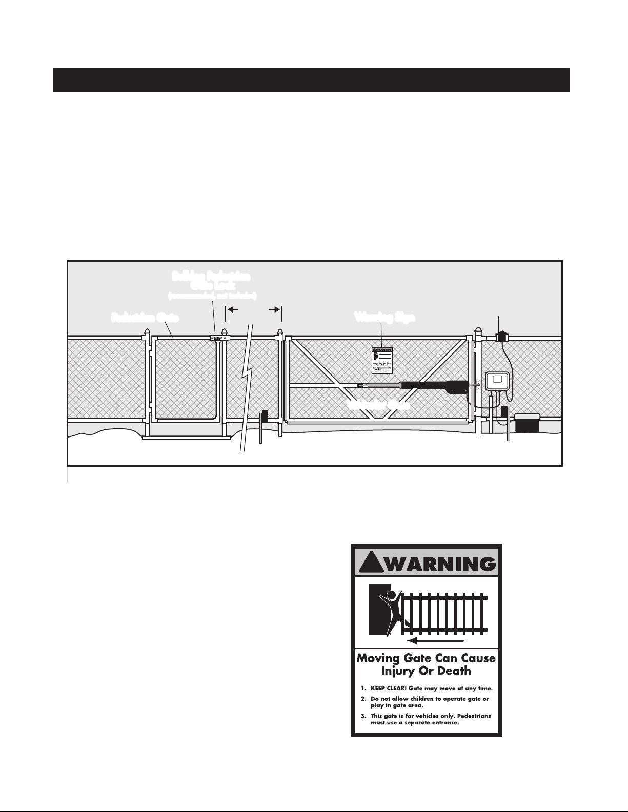
Horizontal Support
Gate Swings Evenly and Freely
Hung Firmly and Plumb
Receiver
Post Bracket
Control Box
Fence Post Set in Concrete
Run 1000' (max.) of low
voltage wire to control
box from transformer
(wire not included).
Power Cable
Closed Position Stop Plate
PVC conduit (not included)
to protect wire from lawn
mowers and weed eaters.
12 Volt automobile or marine
battery in a weatherproof
battery box (not included).
Gate Bracket
Warning Sign
Single Gate Opener
120 Volt indoor
Transformer
(surge protector
not supplied)
MM660
Installation Manual
For more information on Mighty Mule’s full line of Automatic Gate Operators and Access Controls visit
Printed in China for GTO Access Systems, LLC.
This product meets the requirements of UL325 6th Edition, 2016, the standard for gate
operator safety.
For 24 hour/day, 7 day/week Technical Service visit http://support.gtoinc.com
Mighty Mule® is the retail brand of GTO Access Systems, LLC
3121 Hartseld Road • Tallahassee, FL 32303
Example of nished installation
(installations vary slightly on different types of gates)
GTO Sales: 800-543-4283 • Fax 850-575-8912
GTO Technical Service 800-543-1236
www.mightymule.com
ACCESS SYSTEMS, LLC
Copyright© 2016 GTO Access Systems, LLC
Document Number: R66008 REV A (12-19.16)
Page 2

WARNING
This equipment meets Underwriters Laboratory Standard 325 (UL 325). However, gate equipment has
hazards associated with its use and therefore by installing this product the installer and user accept
full responsibility for following and noting the installation and safety instructions. Failure to follow
installation and safety instructions can result in hazards developing due to improper assembly. You agree
to properly install this product and that if you fail to do so GTO Access Systems, LLC, shall in no event
be liable for direct, indirect, incidental, special or consequential damages or loss of prots whether based
in contract tort or any other legal theory during the course of the warranty or at any time thereafter. The
installer and/or user agree to assume responsibility for all liability and use of this product releasing GTO
Access Systems, LLC, from any and all liability. If you are not in agreement with this disclaimer or do
not feel capable of properly following all installation and safety instructions you may return this product
for full replacement value.
READ ALL INSTRUCTIONS CAREFULLY AND COMPLETELY before attempting to install and
use this automatic gate operator. This gate operator produces a high level of force. Stay clear of the unit
while it is operating and exercise caution at all times.
ALL AUTOMATIC GATE OPERATORS ARE INTENDED FOR USE ON VEHICULAR GATES ONLY.
Product Usage
The Mighty Mule Gate Operator meets all of the safety requirements of a Class I Residential Vehicular Gate Operator and is
intended for use solely with vehicular swing gates in single-family residential applications that meet the Class I category listed
in the table below.
Vehicular Gate Operator Class Categories
Residential Vehicular Gate Operator-Class I:
A vehicular gate operator (or system) intended for
use in garages or parking areas associated with a
residence of one-to-four single families.
Commercial/General Access Vehicular Gate
Operator-Class II: A vehicular gate operator (or
system) intended for use in a commercial location
or building such as a multi-family housing unit (ve
or more single family units), hotel, garages, retail
store, or other buildings accessible by or servicing
the general public.
Industrial/Limited Access Vehicular Gate
Operator–Class III: A vehicular gate operator (or
system) intended for use in an industrial location or
building such as a factory or loading dock area or
other locations not accessible by or intended to service
the general public.
Restricted Access Vehicular Gate Operator–
Class IV: A vehicular gate operator (or system)
intended for use in an industrial location or building
such as a factory or loading dock area or other
locations not accessible by or intended to service the
general public.
i
Page 3

Table of Contents
PLEASE READ THIS FIRST ________________________________________________________ 1
IMPORTANT SAFETY INFORMATION _______________________________________________ 2
TECHNICAL SPECIFICATIONS _____________________________________________________ 9
BEFORE YOU BEGIN ____________________________________________________________ 10
Check Direction of Gate Swing ___________________________________________________ 10
Check Existing Gate Size and Material _____________________________________________ 10
Check for Proper Gate Installation _________________________________________________ 10
Column Installation Information ___________________________________________________ 11
Items Included _________________________________________________________________ 11
Tools Needed _________________________________________________________________ 12
Items Not Included _____________________________________________________________ 12
GATE OPENER INSTALLATION ___________________________________________________ 13
Mounting Pull-to-Open Opener to Gate ____________________________________________ 13
Closed Position Stop Plate Installation ______________________________________________15
Mounting Push-to-Open Opener to Gate ____________________________________________ 16
Closed Position Stop Plate Installation ______________________________________________18
CONTROL BOX INSTALLATION ___________________________________________________ 19
Control Box Installation _________________________________________________________ 19
Receiver Installation ____________________________________________________________20
Connecting the Battery __________________________________________________________ 21
Transformer Wiring Installation ___________________________________________________ 21
SOLAR PANEL INSTALLATION ____________________________________________________ 23
CONTROL BOX SETTINGS _______________________________________________________ 25
DIP Switches __________________________________________________________________ 25
Setting Pull-to-Open (Closed) Gate Limit ___________________________________________ 26
Resetting Closed Gate Limit ______________________________________________________ 26
Setting Push-to-Open (Open) Gate Limit ___________________________________________ 27
Resetting Open Gate Limit _______________________________________________________ 27
Setting Obstruction Stall Force and Auto Close Time __________________________________ 28
Setting Your Personal Code ______________________________________________________ 28
CONNECTING ADDITIONAL DEVICES _____________________________________________ 30
Input Connections _______________________________________________________________31
Connecting Accessories _________________________________________________________ 32
Connecting GTO Automatic Lock _________________________________________________ 32
Connecting Other Auxilary Devices _________________________________________________32
MAINTENANCE & TROUBLESHOOTING ___________________________________________ 32
Maintenance Tips _______________________________________________________________32
Troubleshooting Guide ___________________________________________________________33
Page 4

Please Read This First!
Thank you for purchasing a Mighty Mule Gate
Operator—GTO's "do-it-yourself" automatic gate
operator! When correctly installed and properly used,
your Mighty Mule Gate Operator will give you many
years of reliable service. Please read the following
information and watch the enclosed video to ensure
you have the correct system for your particular
needs. Furthermore, this manual and the DVD will
enable you to properly install your Mighty Mule Gate
Operator.
The Mighty Mule Gate Operator is designed for
installation on a pull-to-open single leaf gate (gates
that open into the property). By purchasing an
accessory bracket, the Mighty Mule Gate Operator can
accommodate a push-to-open single leaf gate (gates
that open out from the property). The gate must not
exceed 18 feet in length and weigh more than 350
pounds or exceed 8 feet in length and weigh more
than 850 pounds (please see Technical Specications
on page 9). The Mighty Mule Gate Operator can be
used on vinyl, aluminum, chain link, farm tube, and
wrought iron gates. Use on solid surface gates is
not recommended. Solid surface gates have a high
resistance to the wind. If the wind is strong enough,
the operator will obstruct and stop.
The Mighty Mule Gate Operator accommodates
extra transmitters, digital keypads, solar panels,
push buttons, automatic gate locks, and other access
control products. These optional accessories (see the
Mighty Mule Accessory Catalog) are available at most
stores. Your store should be able to special order any
accessory not in stock. If your store cannot special
order accessories, please call the Mighty Mule Sales
Department (800-543-GATE).
The Mighty Mule Gate Operator features Dual Sense
Technology™. This feature makes the gate stop and
reverse direction when it comes in contact with an
obstruction. This is factory set to the most sensitive
setting and must be adjusted during installation.
The Mighty Mule Gate Operator also has an adjustable
auto-close feature. After the gate reaches the fully
open position, it can be set to remain open up to 120
seconds before automatically closing. Pressing the
transmitter button at any time after the gate opens fully
will cause it to close immediately. OFF is the factory
setting; meaning the gate will stay open until you press
the transmitter (or keypad, etc.) again.
NOTE—If your application requires any of the
following:
• Swing gates longer than 18 feet or weighing
more than 850 pounds
• Slide gates
• Heavy duty or commercial uses
• Professional installation
Go to www.gtoaccess.com for a dealer or retailer near
you or call (800) 543-4283 for information about our
Linear PRO Access professional line of gate operators
and accessories. Our Sales Department will be glad to
give you the name and phone number of a Linear PRO
Access dealer near you
.
BEFORE YOU BEGIN TO INSTALL YOUR AUTOMATIC GATE OPERATOR:
watch the enclosed video and read these instructions carefully and completely
to become familiar with all parts and installation steps. The video is only designed as an
overview of the installation procedure. You must read the installation manual for detailed
instructions on gate operator safety and proper use of the gate operator.
1 MM660 Installation Instructions
Page 5
Important Safety Information
Because automatic gate operators produce high levels
of force, consumers need to know the potential hazards
associated with improperly designed, installed, and
maintained automated gate operator systems. Keep in
mind that the gate operator is just one component
of the total gate operating system. Each component
must work in unison to provide the end user with
convenience, security, and safety.
This manual contains various safety precautions and
warnings for the installer end user. Because there
are many possible applications of the gate operator,
the safety precautions and warnings contained in
Because Mighty Mule automatic gate operators are only part of the total gate operating system, it is the
responsibility of the installer and end user to ensure that the total system is safe for its intended use.
this manual cannot be completely exhaustive in
nature. They do, however, provide an overview of
the safe design, installation, and use of this product.
CAREFULLY READ AND FOLLOW ALL
SAFETY PRECAUTIONS, WARNINGS, AND
INSTALLATION INSTRUCTIONS TO ENSURE
THE SAFE SYSTEM DESIGN, INSTALLATION,
AND USE OF THIS PRODUCT.
Warnings in this manual are identied with
this warning symbol. The symbol identies
conditions that can result in damage to the operator or
its components, serious injury, or death.
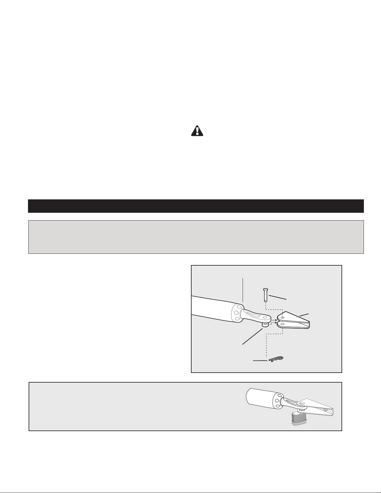
Manually Opening and Closing Gate
CAUTION
The gate will move freely and uncontrolled when the gate operator is removed from the gate. ONLY disconnect the operator when the control box power switch is OFF and the gate is NOT moving.
Disconnecting the Operator
1. Turn control box power switch OFF.
2. Remove hairpin clip, clevis pin, and bushing from
either the front or rear mounting point.
3. Remove the operator from the mount.
The gate can be opened and closed manually
when the operator is disconnected.
NOTE: Substitute a Pin Lock for the clevis pin on the front mount of the
gate operator to prevent unauthorized removal of the operator from the
gate (see accessory pages in back of this book).
Front Mount
Clevis Pin
Gate Bracket
Bushing
Hairpin Clip
MM660 Installation Instructions 2
Page 6
Important Safety Information
For the Installer and End User
WARNING
To reduce the risk of injury or death:
1. READ AND FOLLOW ALL INSTRUCTIONS.
2. Never let children operate or play with gate controls. Keep the remote
control away from children.
3. Always keep people and objects away from the gate. NO ONE
SHOULD CROSS THE PATH OF THE MOVING GATE.
4. Test the gate operator monthly. The gate MUST reverse on contact with
a rigid object or stop when an object activates the non-contact sensors.
After adjusting the force or the limit of travel, retest the gate operator.
Failure to adjust and retest the gate operator properly can increase the
risk of injury or death.
5. Use the manual/emergency release only when the gate is not moving.
6. KEEP GATES PROPERLY MAINTAINED. Read the
user’s manual. Have a qualied service person make repairs to
gate hardware.
7. The entrance is for vehicles only. Pedestrians must use separate entrance.
8. The gate must be installed in a location that provides adequate
clearance between it and adjacent structures when opening and
closing to reduce the risk of entrapment. Swinging gates must
not open into public access areas.
9. SAVE THESE INSTRUCTIONS.
I. Before Installation
1. Verify this operator is proper for the type and size of gate,
frequency of use and class of the gate system.
2. Make sure the gate has been properly installed and swings
freely in both directions. Repair or replace all worn or damaged gate hardware prior to installation. A freely moving
gate will require less force to operate and will enhance the
performance of the entrapment protection devices used with
the system (see page 10).
3. Review the operation of the system to become familiar with
its safety features. Understand how to disconnect the operator
for manual gate operation (see page 2).
4. The gate and operator installation must comply with any applicable local codes.
ZONE 1
ZONE 2
5. This gate operator is intended for vehicular gates only. A
separate entrance or gate must be installed for pedestrian use
(see page 7).
6. Always keep people and objects away from the gate and its
area of travel. No one should cross the path of a moving gate.
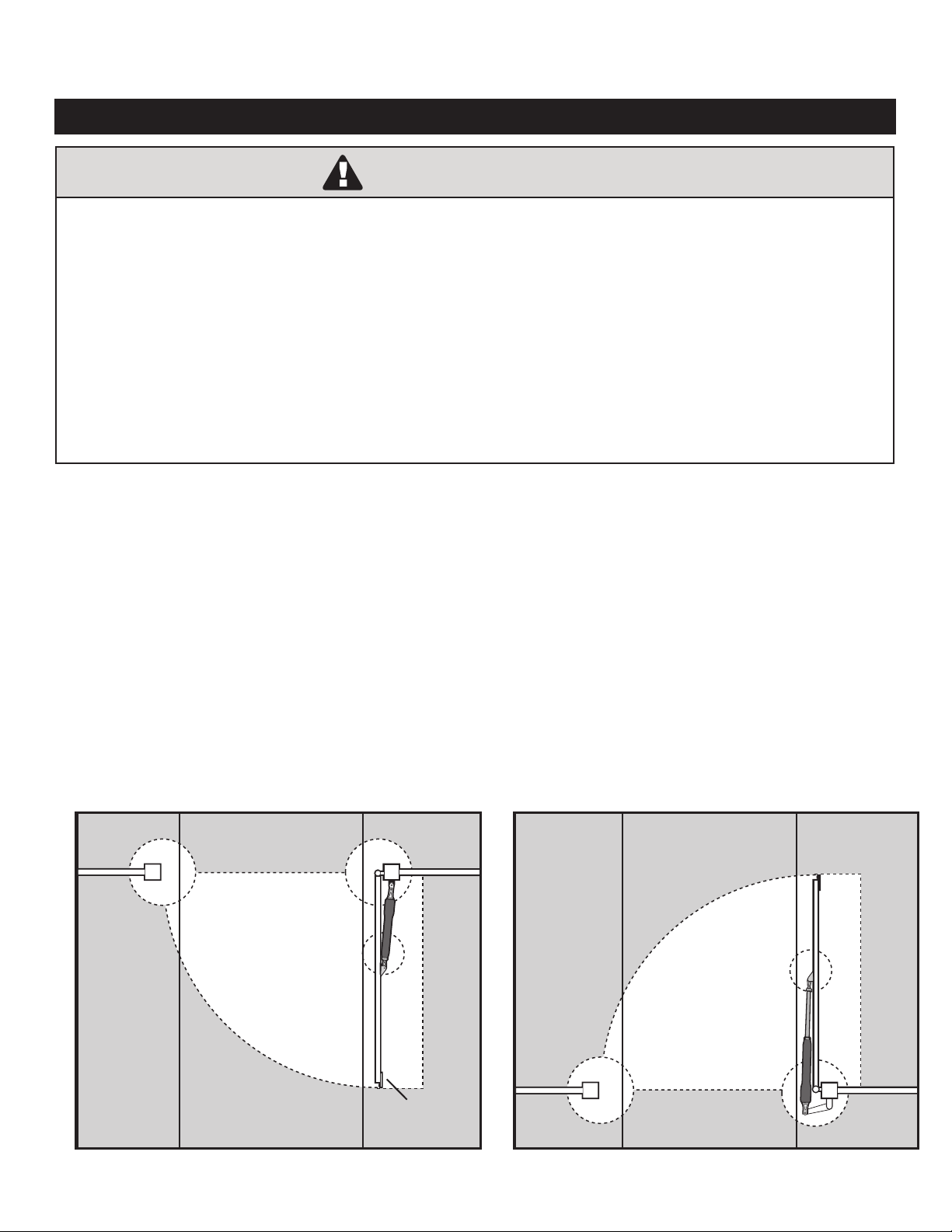
7. Identify all of the entrapment zones for the type of installation. An entrapment zone is an area around the automatic gate
system where a person or object could be caught that increase
the risk of injury. Entrapment zones must be eliminated,
guarded or protected.
8. When designing a system that will be entered from a highway
or main thoroughfare, make sure the gate system is placed far
enough from the road to prevent trafc congestion.
Gate in the
Entrapment
Zones for a
Push-To-Open
Application
Open Position
ZONE 3
Entrapment
Zones for a
Pull-To-Open
Application
Driveway
3 MM660 Installation Instructions
ZONE 5
ZONE 4
Gate in the
Open Position
ZONE 1
ZONE 5
ZONE 3
ZONE 4
Driveway
ZONE 2
Page 7
Important Safety Information
For the Installer and End User
Typical Entrapment Zones are shown in the diagrams on page 3:
Zone 1 – leading edge of the gate and the fence post.
Zone 2 – between the gate and the gate post.
Zone 3 – the path of the gate.
Zone 4 – the space between the gate in the open position and any object such as a wall, fence, tree, etc.
Zone 5 – pinch points between the operator and gate.
II. During Installation
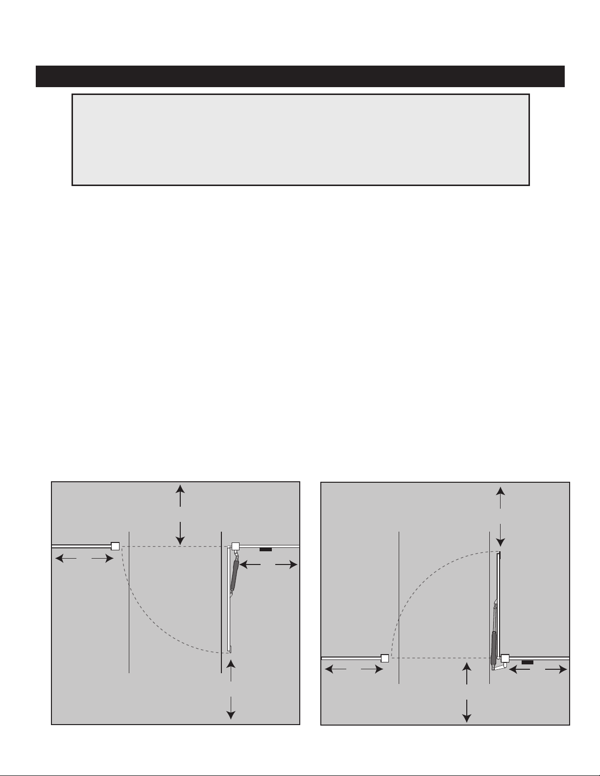
4. If push buttons or key switches are installed, they
1. Install the gate operator on the inside of the property and fence line. DO NOT install an operator
on the outside of the gate where the public has
access to it.
2. Be careful with moving parts and avoid close
proximity to areas where ngers or hands could
be pinched.
3. Devices such as contact sensors (sensing
edges) and non contact sensors (photo beams)
provide additional protection against vehicle
damage.
should be within sight of the gate, located at least
10 feet from any moving part of the gate (see
diagram below). Never install any control device
where a user will be tempted to reach through
the gate to activate the gate operator.
5. Do not activate your gate operator unless you can
see it and can determine that its area of travel is
clear of people, pets, or other obstructions. Watch
the gate through its entire movement.
6. Secure outdoor or easily accessed gate operator
controls in order to prohibit unauthorized use of
the gate.
NEVER install
any control device
within gray area
Pull-To-Open
Application
10'
Moving Gate
10'
Area
Driveway
10'
10'
NEVER install
any control device
within gray area
Push-To-Open
Application
Moving Gate
Area
10'
Driveway
10'
10'
10'
MM660 Installation Instructions 4
Page 8

Important Safety Information
For the Installer and End User
III. After Installation
1. Attach the warning signs (included) to each side
of the gate to alert the public of automatic gate
operation. It is your responsibility to post warning
signs on both sides of your gate. If any of these
signs or warning decals becomes damaged,
illegible, or missing, replace them immediately.
Contact GTO for free replacements.
2. The gate is automatic and could move at any
time, posing serious risk of entrapment. No one
should be in contact with the gate when it is
moving or stationary.
3. Do not attempt to drive into the gate area while
the gate is moving; wait until the gate comes to a
complete stop.
4. Do not attempt to “beat the gate” while the gate is
closing. This is extremely dangerous.
5. Do not allow children or pets near your gate.
Never let children operate or play with gate
controls. Keep the remote control away from
children and unauthorized users; store controls
where children and unauthorized users do not
have access to them.
6. KEEP GATES PROPERLY MAINTAINED.
Always turn power to operator OFF before
performing any maintenance. See page 33 for
maintenance procedures.
7. To operate this equipment safely, YOU must
know how to disconnect the operator for manual
gate operation (see page 2). If you have read the
instructions and still do not understand how to
disconnect the operator, contact the Mighty Mule
Service Department.
8. Disconnect the operator ONLY when the power
is TURNED OFF and the gate is NOT moving.
9. Make arrangements with local re and law
enforcement for emergency access.
10. Distribute and discuss copies of the
IMPORTANT SAFETY INFORMATION
section of this manual with all persons
authorized to use your gate.
11. IMPORTANT: Save these safety instructions.
Make sure everyone who is using or will be
around the gate and gate operator are aware
of the dangers associated with automated gate
systems. In the event you sell the property
with the gate operator or sell the gate operator,
provide a copy of these safety instructions to
the new owner.
Should you need a replacement manual, a copy
can be obtained by downloading one from the
Mighty Mule web site (www.mightymule.com),
by contacting GTO, at 3121 Hartseld Road,
Tallahassee, Florida 32303 or by calling 1-800543-4283 and requesting a duplicate copy. One
will be provided to you.
5 MM660 Installation Instructions
Page 9
Important Safety Information
For the Installer and End User
Mighty Mule gate operators utilize Dual Sense Technology™ entrapment protection. Dual Sense Technology™ is built into every Mighty Mule and provides
redundant methods of entrapment protection for open
and close gate directions.
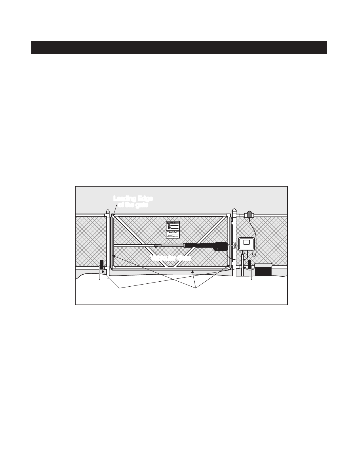
In addition to Dual Sense Technology, every Mighty
Mule gate controller has provisions for the connection
of additional obstruction detection devices such as
sensing edges and photo beams.
These devices may be located where there is an
increased risk of obstruction. Refer to the diagram
below.
Leading Edge
of the gate
One or more edge sensors may be located at the leading edge, bottom edge, and post edge, both inside and
outside of a vehicular swing gate system.
Wiring to sensors must be located and arranged so the
wiring between the sensor and the gate operator is not
subjected to mechanical damage.
A wireless sensor such as one that
transmits radio frequency (RF) signals to the gate
operator for obstruction protection functions shall be
located where the transmission of the signals is not
blocked or impeded by building structures, natural
landscaping or similar objects.
Vehicular Gate
Photo Beams
(recommended, not included)
Sensing Edges
(recommended, not included)
Entrapment and Obstruction Protection
Mighty Mules’s Dual Sense Technology™ provides entrapment protection, even when properly adjusted. Since all
installations are different, you may need to add photo beams or sensing edges to help prevent damage to vehicle or other
items that could be hit by a moving gate.
Entrapment Alarm
The Mighty Mule Automatic Gate Operator is designed to stop and reverse the gate when the gate comes in contact with
an obstruction. Additionally, these operators are equipped with an audio entrapment alarm which will activate if the unit
obstructs twice while opening or closing. This alarm will sound for a period of 5 minutes, or until the operator receives
an intended signal from a hard wired entry/exit source (e.g. push button control or keypad) and the gate returns to a fully
open or fully closed position. Turning the power switch on the control box OFF and back ON will also deactivate the
alarm. Wireless controls such as transmitters and wireless keypads will not deactivate the alarm.
MM660 Installation Instructions 6
Page 10
Important Safety Information
Installing Warning Signs and Pedestrian Gates
Warning signs alert people of automatic gate operation and are required when installing Mighty Mule Automatic
Gate Operators. A minimum of two WARNING SIGNS must be installed in the area of the gate. Each sign is to be
visible by persons located on the side of the gate on which the placard is installed.
The operator is intended for installation only on gates used for vehicles. Pedestrians must be supplied with a
separate access. The pedestrian access shall be designed to promote pedestrian usage. Locate the gate such that
persons will not come in contact with the vehicular gate during the entire path of travel of the vehicular gate.
We recommend using the GTO Bulldog Pedestrian Gate Lock (Call the GTO Sales Department at 800-543-4283)
for controlled access.
Bulldog Pedestrian
Gate Lock
(recommended, not included)
Pedestrian Gate
7 foot
Warning Sign
Warning Signs
The gate operator is provided with 2 safety warning signs.
The signs MUST be installed on the front and back of the
gate where they will be visible in the area of the gate.
Permanently secure each warning sign to the gate.
Immediately replace a damaged or missing warning sign.
Vehicular Gate
!
7 MM660 Installation Instructions
Page 11
Important Safety Information
Required Safety Precautions for Gates
These warning labels should be found at the locations specied below. If any of them are missing,
immediately contact GTO for replacements.
660®
1-800-543-GATE (4283) • www.mightymule.com
!
WARNING
MOVING GATE
Can Cause Injury or Death
1. KEEP CLEAR! Gate may move at any time.
2. Do not allow children to operate gate or play in gate area.
3. This gate is for vehicles only. Pedestrians must use separate entrance.
®
www.mightymule.com
1-800-543-GATE (4283)
TO MANUALLY OPEN AND CLOSE THE GATE
1. Turn opener power switch OFF.
2. Disconnect front and rear mount from mounting brackets.
3. Remove opener from mounting brackets and move gate.
Disconnect opener ONLY when the power switch is OFF and
the gate is not moving.
Control Box label with Manual Open and
Close instructions
MM600 SERIES DC Swing Gate Operator
P/N MM660
Conforms to UL STD 325
Certified to CSA STD C22.2 No.247
Maximum Gate: 850 lb. (385.5 kg); 18 ft. (5.5 m)
Voltage: 12 Vdc; Frequency: 0 Hz; Power: 25 W
9901178
MMDDYY
Product identification label (1) installed on side of
control box.
Class I Vehicular Swing Gate Operator.
GTO Access Systems, LLC - Tallahassee, Florida USA
Serial Number: MM660-0000000
MM660 Installation Instructions 8
Page 12

Technical Specifications
Mighty Mule 660 Gate Opener
DRIVE
• Low friction screw drive (linear actuator) rated for -5 ºF to
+160 ºF (-20 ºC to +71 ºC). Use of heater bands on arm and
control box will enhance performance in extreme cold temperatures.
• Powered by a 12 V motor with integral case hardened steel
gear reducer. Motor speed reduced to 260 rpm. Generates 680
ft. lb. of torque at 12 V.
• Maximum opening arc of 110º. Approximate opening time
(90º): 20 seconds, depending on weight of gate.
POWER
• The system is powered by a 12 Vdc, 7.0 Ah, sealed,
rechargeable acid battery.
• Battery charge is maintained by a 120 Vac, 18 Vac output transformer. One lade-style control board fuse is rated for 15 A.
NOTE: The transformer should not be directly connected
to any battery. Do not replace fuses with higher ampere
rated fuses; doing so will void your warranty and may
damage your control board.
• OPTIONAL: Battery charge is maintained by GTO Solar Panel
Charger Kit (5 Watt minimum).
CONTROL
• The Mighty Mule microprocessor-based control board is set for
single leaf, pull-to-open gate installations. DIP switches can be
adjusted to accommodate an optional kit for push-to-open gates
(see Accessory Catalog).
• A circuit on the control board regulates charging. “Sleep draw”
is 25 mA; “active draw” is 2 to 5 A.
• Auto-memorization of digital transmitter code.
• GTO remote-mounted RF receiver tuned to 318 MHz.
• Operator length with push-pull tube fully retracted is
40-1/4” mounting point to mounting point. Max stroke 20”.
• Adjustable auto-close timer (3 to 120 s), and Dual Sense Technology Stall Force.
• Power terminal block accommodates a transformer or solar
panels. NOTE: Do not use solar panel and transformer at
the same time.
• DIP switches simplify setup of gate operator.
• Accessory terminal block fully compatible with push
button controls, digital keypads, loops, etc.
• Control board allows connection of edge sensors and photo-
electric sensors.
• Audio entrapment alarm sounds if unit encounters an
obstruction twice while opening or closing.
OPERATIONAL CAPACITY
• The Gate Capacity Chart shows approximate cycles, per day,
you could achieve prior to the battery depleting to a state where
the unit will not function. This chart reects a Mighty Mule
Automatic Gate Opener when charging with a transformer.
Actual cycles may vary slightly depending upon the type and
condition of gate and installation.
NOTE: “NR” indicates this size
and weight combination is not
recommended for the
Mighty Mule 660.
NOTE: Ball bearing hinges
should be used on all gates
weighing over 250 lb.
To determine the number of cycles the gate operator will perform using solar panels (see page 23).
* An operation cycle is one full opening and closing of the gate.
Mighty Mule 660 Gate Capacity /Cycle Chart
Estimated number of daily cycles, based on use with a transformer and one(1) 12 Volt battery.
Number of Cycles* Per Day
Gate Weight
850 lbs.
750 lbs.
650 lbs.
550 lbs.
450 lbs.
350 lbs.
250 lbs.
150 lbs.
100 lbs.
50 lbs.
135
145
155
165
175
185
195
205
215
225
5’ - 6’
125
135
145
155
165
175
185
195
205
215
8’
NR
125
135
145
155
165
175
185
195
205
10’
Gate Length
NR
NR
125
135
145
155
165
175
185
195
12’
These specications are subject to change without notice.
NR
NR
NR
125
135
145
155
165
175
185
14’
NR
NR
NR
NR
125
135
145
155
165
175
16’
NR
NR
NR
NR
NR
125
135
145
155
165
18’
9 MM660 Installation Instructions
Page 13
Before You Begin
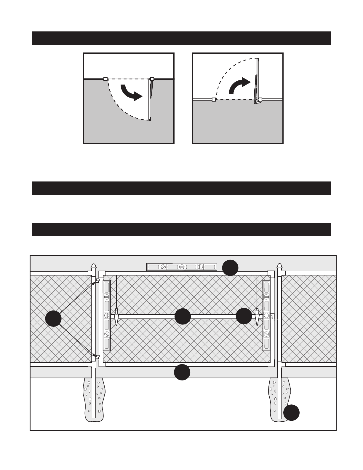
A - Level
B - Plumb
C - Free Swinging
Check Direction of Gate Swing
(Requires Push-To-Open Bracket
#FM148—NOT INCLUDED)
Your Property Your Property
Pull-to-Open Option
Instructions begin on
page 13
Push-to-Open Option
Instructions begin on
page 16
Check Existing Gate Size and Material
• Gate size: Up to 18 feet or up to 850 lbs—See chart
on page 9.
• Type of gate material: Vinyl, aluminum, chain link,
farm tube, wrought iron, wood (not recommended for
solid surface gates).
IMPORTANT: Check for Proper Gate Installation
For the Mighty Mule to work properly, gate must be plumb, level, set in concrete, swing freely and not touching
the ground and have good working hinges.
A
F
E
B
MM660 Installation Instructions 10
C
D - Secured Posts in Concrete
E - Centerline Mounting
F - Good Working Hinges (ball
bearing hinges are recommended
on gates over 250 pounds)
D
Page 14
Before You Begin
Gate Grounding (recommended)
Metal Gate
Post
6 AWG Wire
8 Foot Ground Rod
5/8” Copper Clad Steel (not included)
- available at local homecenter and hardware stores -
Ground Rod
Clamp
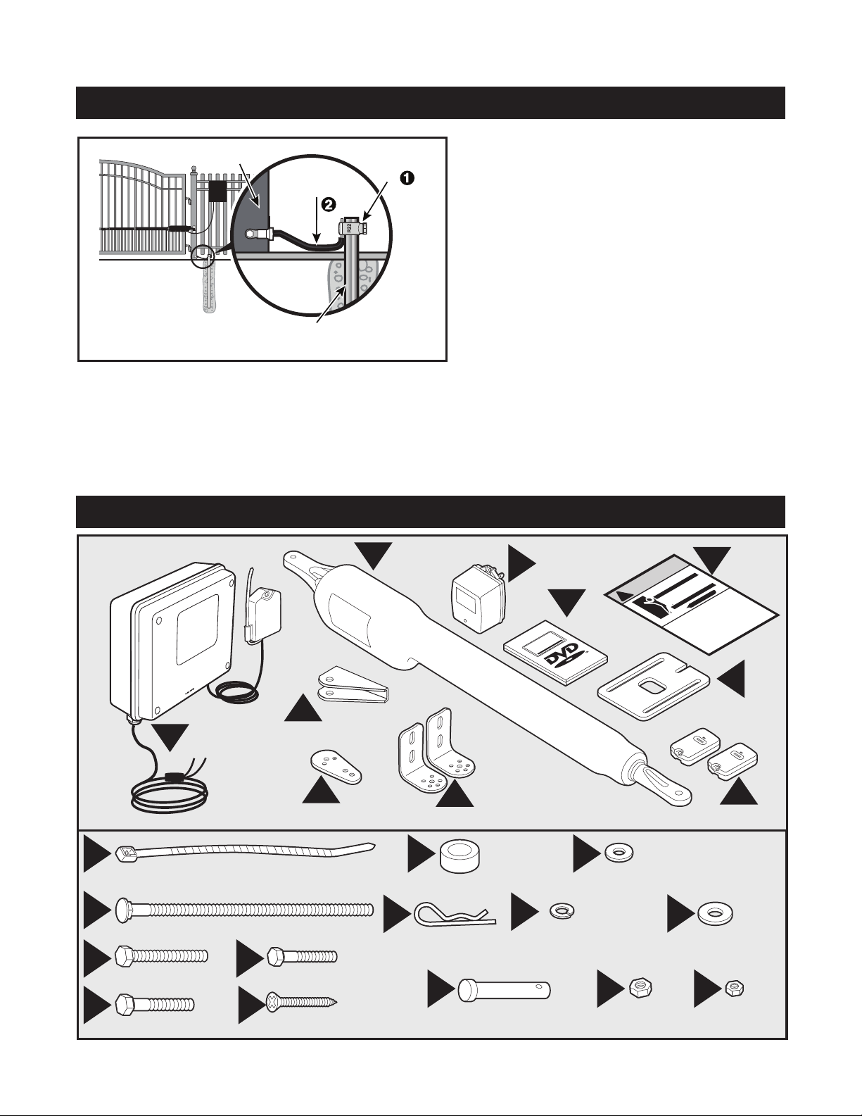
Items Included
• Shorter wire (6 AWG) is better, 1 to 2 feet recommended.
• Bolt ring terminal at end of cable 4 - 6 inches above ground
level.
R4196 Kit Includes:
• Ground Rod Clamp
• 6 AWG Wire (3 feet)
NOTE: No grounding system absolutely protects against
lightning strikes. If installed correctly, a grounding system will
help minimize damage to your gate opener.
B
Operator
Arm
Gate Bracket
F
Receiver and
A
Control Box
H
Post Pivot Bracket
L M
8” Nylon Cable Tie (14)
P
3/8” x 8” Bolt (4)
T
3/8” x 2-3/4” Bolt (2)
V
3/8” x 2” Bolt (1)
U
5/16” x 1-3/4” Bolt (1)
W
2” Mounting Screw (5)
3/8” Bushing (2)
Q
Hairpin Clip (2)
Transformer Warning
C
WARNING
D
Installation
Installation Overview for the...
!
Video
I
Post Brackets
O
5/16” Washer (1)
R
3/8” Lock Washer (7)
X Y Z
3/8” x 1-1/2” Clevis Pin (2)
3/8” Nut (7)
E
Injury Or Death
Moving Gate Can Cause
1. KEEP CLEAR! Gate may move at any time.
play in gate area.
2. Do not allow children to operate gate or
must use a separate entrance.
3. This gate is for vehicles only. Pedestrians
J
Closed Position
Stop Plate
K
Transmitters (2)
S
3/8” Washer (9)
5/16” Nut (1)
Sign
11 MM660 Installation Instructions
Page 15

Before You Begin
Tools Needed
3/8” Bit
Drill
Level
Clamp
5/16” Bit
Pliers
x2
Items Not Included
• 12 Volt lawn tractor or automotive battery and a
weather proof case.
• Low voltage wire will be needed to run from the
transformer to the control box; length depends
upon the distance between the transformer power
supply and the control box. See Transformer Wiring
Installation on page 20, and the accessory catalog.
• PVC conduit.
Hack Saw
9/16”
wrench
Adjustable
Wrench
Pen
1/2”
wrench
Philips Head
Screwdriver
Wire
Stripper
Center
Punch
Hammer
Flat Head
Screwdriver
Small
Flat Head
Tape
Measure
• Surge protection for transformer.
• Some types of installations require u-bolts.
• If the gate is a push-to-open you will need to
purchase a PUSH-TO-OPEN bracket, refer to page
16 in Installation Manual for more information.
• Additional washers or a metal plate may be needed
for wooden post.
• If your gate is more than 1000’ away from an ac
power source you will need to use at least one
• Weatherproof cover for outdoor outlet and
transformer.
Mighty Mule® 5 watt solar panel to trickle charge
the battery. See the accessory catalog (Do not use
both transformer and solar).
• Strain relief bushing for wiring accessory devices to
control box.
• If post the gate is hinged on is more than 6”, bolts
• If you have thin walled tube or panel gates, see
longer than 8” are needed.
Recommended Reinforcement Examples after Step 3
of “Mounting Pull-to-Open Opener to Gate” section
(page 13).
• Depending on the type of gate, a horizontal cross
member or mounting plate may be needed to mount
the front of the opener and gate bracket to the gate.
See Gate Bracket Mounting Examples after Step 3 of
“Mounting Pull-to-Open Opener to Gate” section.
MM660 Installation Instructions 12
Page 16

Gate Opener Installation
Your Property
Mounting Pull-to-Open Opener to Gate
1
V
I
H
I
Assemble post bracket parts.
S
R
Y
3
If you are installing a push-to-open gate opener - skip to page 16.
2
X
Gate
Bracket
B
M
Q
Attach opener to gate bracket and secure with required
hardware.
Reinforcement and Gate Bracket Mounting
Steel Pipe Cut in Half
(not supplied)
M
X
Gate
Bracket
Q
F
With Gate in OPEN position, using clamps, secure opener to
gate post and center cross member of gate.
4
2
1
Thin Walled
Tube Gate
FRONT VIEW
Panel
Gate
1” x 6” Wood Reinforcement
Recommended reinforcement and gate bracket mounting
examples.
5
2" Min. - Pinch-Point Clearance
Gate
Bracket
2
Wood or Metal
Reinforcement
(not supplied)
SIDE VIEW
Mounting Plate
Created for
Decorative Gate
(required but not
supplied)
Remove excess bolt length
with hacksaw or bolt cutters
Top View
20" MAX.
Closed
2" Min.
1
Position
Open
Position
Remove clevis pin from the gate bracket and support loose
opener.
13 MM660 Installation Instructions
Swing gate and opener arm to the CLOSED position-check
clearance/binding by inspecting alignment. Arm stroke should
be maximum of 20”. TIP: Turning the pivot bracket over gives
more hole alignment options for the post pivot bracket assembly.
Page 17

Gate Opener Installation
Your Property
Mounting Pull-to-Open Opener to Gate
6
2
1
OPEN gate and reattach opener with clevis pin. Check for level.
Clamp securely.
8
7
U
O
Z
Secure post pivot bracket to post bracket when clearances are
OK (Step 5) in both open and closed positions.
9
Mark middle of post bracket slots on fence post. Mark middle of
gate bracket slots on gate cross support.
10
Drill 3/8” holes completely through gate post and gate cross
support.
MM660 Installation Instructions 14
Remove clamps, post bracket, gate bracket, and opener. Then
use a hammer and center punch to dimple hole positions for
drilling.
11
Y
Attach post bracket assembly to fence post. NOTE: Must be
through bolted.
S
R
P
Page 18

Gate Opener Installation
J
1
Your Property
12
T
14
Mounting Pull-to-Open Opener to Gate
13
R
Y
S
Attach and secure opener assembly to brackets.Attach gate bracket assembly to gate cross support.
1
2
15
2
1
Check for level. Adjust post bracket if necessary. After the
opener is level, remove the opener from the gate.
Closed Position Stop Plate Installation
Fully open gate. Attach gate stop with one of the following:
• U-bolts—tube and chain link gates (Not included)
• Wood/lag screws—at aluminum/wood supports (Not included).
15 MM660 Installation Instructions
Tighten all bolts and remove excess length on post and gate
bracket bolts with hacksaw.
2
1
1
2
Position gate stop with gate CLOSED to fence post. Tighten
fasteners. Cut off excess bolt length.
Return the gate to the full open position and reinstall the Mighty
Mule. To complete a pull-to-open installation, proceed to page 19.
Page 19

Gate Opener Installation
Your Property
Mounting Push-to-Open Opener to Gate
If you are installed a pull-to-open gate opener - skip to page 19.
1
V
S
Y
Assemble post bracket parts. NOTE: A Push-to-Open Bracket
FM148 is required for this type of installation (not included).
I
PTO
Bracket
FM148
11”
I
R
3
2
X
B
M
Q
Attach opener to gate bracket and secure with hardware required.
Reinforcement and Gate Bracket Mounting
Steel Pipe Cut in Half
(not supplied)
Gate
Bracket
M
Gate
Bracket
Q
X
F
With gate in CLOSED position, using clamps, secure opener to
gate post and center cross member of gate.
4
1
2
Thin Walled
Tube Gate
FRONT VIEW
Panel
Gate
1” x 6” Wood Reinforcement
Recommended reinforcement and gate bracket mounting
examples.
5
Maximum Stroke 20”
Gate
Bracket
Top View
Wood or Metal
Reinforcement
(not supplied)
SIDE VIEW
Mounting Plate
Created for
Decorative Gate
(required but not
supplied)
Remove excess bolt length
with hacksaw or bolt cutters
1
Open
Position
2" minimum
pinch-point clearance
Closed
Position
2
Swing gate to OPENED position. Check clearance/binding by inspecting
the alignment. The Maximum stroke is 20 inches. Secure post pivot bracket
Remove clevis pin from the gate bracket and support loose
opener.
MM660 Installation Instructions 16
to post bracket as shown in Step 7 on the next page, when clearance is OK
in both open and closed positions. TIP: Turning the pivot bracket over
gives more hole alignment options for the post pivot bracket assembly.
Page 20

Push-to-Open Installation
Your Property
Mounting Push-to-Open Opener to Gate
6
2
CLOSE gate and re-attach opener with clevis pin. Check
for level. Clamp securely.
8
7
U
1
O
Z
Secure post pivot bracket to post bracket when clearance is OK
(Step 5) in both open and closed positions.
9
Mark middle of post bracket slots on fence post. Mark middle of
gate bracket slots on gate cross support.
10
Drill holes completely through gate post and gate cross support.
17 MM660 Installation Instructions
Remove clamps, post, gate brackets, and opener. Then use a
hammer and center punch to dimple hole positions for drilling.
11
S
P
Attach post bracket assembly to fence post. NOTE: Must be
through bolted.
Y
R
Page 21

Push-to-Open Installation
J
1
Your Property
12
T
14
Mounting Push-to-Open Opener to Gate
13
R
Y
S
Attach and secure opener assembly to brackets.Attach gate bracket assembly to gate cross support.
1
2
15
2
1
Check for level. Adjust post bracket if necessary.
Remove bolt excess length on post and gate bracket with hacksaw.
After the bolts are trimmed, remove the opener from the gate.
Closed Position Stop Plate Installation
2
1
1
2
Fully open gate. Attach gate stop on the outside of the gate with
one of the following:
• U-bolts—tube and chain link gates (Not included)
• Wood/lag screws—at aluminum/wood supports (Not included).
Do not tighten.
MM660 Installation Instructions 18
Position gate stop with gate CLOSED to fence post. Tighten
fasteners. Cut off excess bolt length.
Return the gate to the full closed position and reinstall the
Mighty Mule.
Page 22

15
FUSE
BATT +
BATT -
1 2 3 4
ON
OFF
SOFT START OFF
WARNING OFF
OPEN PULL
SLV OPEN DLY.
MODE1 OFF
MODE2 OFF
ON
ON
PUSH
SIMULT.
ON
ON
120 MIN
CHARGING
PWR IN
WHT
BLU
BRN
ORG
RED
BLK
GRN
WHT
BLU
BRN
ORG
RED
BLK
GRN
COM
CYCLE
SAFETY
EXIT
SHADOW
OPEN
EDGE
COM
POWER
INPUT
LOCK
PWR
AUX
RLY
CONTROL OUTPUTS
MASTER OPERATOR2ND OPERATOR
CONTROL INPUTS
AUTO CLOSE TIME STALL FORCE
CLOSE
EDGE
GTO 18VOLT
TRANSF. OR
SOLAR PANEL
GTO
LOCK
AUX
1 2 3 4 5 6 7
BLK
WHT
BLU
BRN
ORG
RED
BLK
GRN
COM
CYCLE
SAFETY
EXIT
SHADOW
COM
MASTER OPERATOR
CONTROL INPUTS
CLOSE
EDGE
Correct
Wrong Wrong
6
3’ Min.
3
W
W
OR
OR
Control Box Installation
Control Box Installation
1
A
Remove control box cover.
2
4’
Max.
3’
Min.
Locate control box mounting area. IMPORTANT: Be sure to mount
box at least 3 feet from AC power and 3 feet off the ground.
4
Mount control box to post or fence using screws.
5
MASTER OPERATOR
4”
Feed 4” of opener cable into box through the empty strain relief.
Tighten strain relief nut to secure cable.
GRN
Insert 7 wires into corresponding color terminals.
WHT
BLU
BRN
19 MM660 Installation Instructions
ORG
RED
BLK
Secure wires in terminals.
Page 23

Control Box Installation
Receiver Installation
1
2
W
10’
Max
NOTE: Once you have completed the installation, you may need to relocate the receiver to get
better reception distance.
Consider the following when mounting the receiver:
• Standard receiver cable length is 10 feet (receivers with a longer cable are available as special
order items; call the Mighty Mule Sales Department). NEVER splice receiver cable!
• Run the cable through PVC conduit to protect it from damage.
• DO NOT run cable through metal conduit because the receiver signal range will be decreased.
• DO NOT run cable through conduit containing AC wire.
• DO NOT place receiver within 3 feet of AC power.
• DO NOT coil excess cable or store it in the control box.
• Do not mount upside down.
• The receiver range can vary from 50 to 100 feet depending upon weather, topography, and
external interference.
W
MM660 Installation Instructions 20
Page 24

Control Box Installation
12 VOLT
12 VOLT
OFF
Connecting the Battery
1
RED WIRE TO
POSITIVE (+) TERMINAL
12 VOLT
BLACK WIRE TO
NEGATIVE (–) TERMINAL
Turn control box power switch OFF. Place the 12 Volt Lawn
Tractor or Automotive battery and weatherproof battery box
(not supplied) within 6 feet of the control box Attach the battery
harness wires from the control box to the battery terminals using
bolts, washers and nuts. Be sure to attach the RED wire to the
POSITIVE terminal and the BLACK wire to the NEGATIVE
terminal.
POSITIVE
NEGATIVE
2
NEGATIVE
12 VOLT
Tighten the bolts, washers, and nuts and place the cover on the
weatherproof box. IMPORTANT: Do not connect the transformer or solar panel directly to the battery. This will cause the
system to fail.
If usIng optIonal solar panel charger Instead of transformer, go to page 23.
POSITIVE
Important: d
o not connect both solar panel and transformer.
Transformer Wiring Installation
WARNING
Before digging contact local authorities to locate underground utilities such as electric and gas service.
8
Top View
Min 3 Ft
Max 1,000 Ft
GTO Transformer
Mounts Here
9
CAUTION: Please
call your power company
before you dig. Failure to
do so could cause injury
or even death.
Locate power outlet and identify wire path to control box.
NOTE: If OUTLET is OUTSIDE use weatherproof cover.
21 MM660 Installation Instructions
Dig trench and lay wire from AC power source to control box.
Use only 16 gauge multi-stranded, low voltage, direct burial
wire (RB509). NOTE: DO NOT use telephone wire or solid core
wire. NEVER splice wires together. We recommend running wire
in PVC conduit.
Page 25

BLK
15
FUSE
BATT +
BATT -
CHARGING
PWR IN
WHT
BLU
BRN
ORG
RED
BLK
GRN
WHT
BLU
BRN
ORG
RED
BLK
GRN
COM
COM
MASTER OPERATOR2ND OPERATOR
AUTO CLOSE TIME
1 2 3 4 5 6 7
POWER
INPUTS
LOCK
PWR
AUX
RLY
CONTROL OUTPUTS
GTO 18VOLT
TRANSFORMER
OR SOLAR
BLK
15
FUSE
BATT +
BATT -
1 2 3 4
ON
STATUS
LEARN RMT
RECEIVER
LEARN
MAST LIMIT
LEARN
SLV LIMIT
OFF
SOFT START OFF
WARNING OFF
OPEN PULL
SLV OPEN DLY.
MODE1 OFF
MODE2 OFF
ON
ON
PUSH
SIMULT.
ON
ON
120 MIN MAX
CHARGING
PWR IN
GTO RCVR.
WHT
BLU
BRN
ORG
RED
BLK
GRN
WHT
BLU
BRN
ORG
RED
BLK
GRN
COM
GRN
BLK
RED
CYCLE
SAFETY
EXIT
SHADOW
OPEN
EDGE
COM
MASTER OPERATOR2ND OPERATOR
CONTROL INPUTS
AUTO CLOSE TIME STALL FORCE
CLOSE
EDGE
1 2 3 4 5 6 7
POWER
INPUTS
LOCK
PWR
AUX
RLY
CONTROL OUTPUTS
GTO 18VOLT
TRANSFORMER
OR SOLAR
SU RGE PROTECTO R
Control Box Installation
Transformer Wiring Installation
11
Use PVC conduit from ground up to control box.
12
11
C
1
1
2
Cut excess cable/strip 1/2” off 2 wires/twist ends. Attach wires to
transformer screw terminals. NOTE: The Mighty Mule power input
is not polarized. The wires can be connected to either terminal.
13
4”
Feed 4” of low voltage wire through strain relief with the battery
harness wire into box and tighten strain relief to secure wires.
14
Wrong Wrong
Correct
CONTROL OUTPUTS
POWER
INPUTS
GTO 18VOLT
TRANSFORMER
OR SOLAR
LOCK
PWR
AUX
RLY
Insert one wire into each 18VAC terminal. The Mighty Mule
power input is not polarized. The wires can be inserted into
either terminal regardless of color.
15
Secure with terminal screws.
Plug in transformer to power outlet. (Use of a surge protector is
highly recommended. If outdoors use weatherproof box.)
MM660 Installation Instructions 22
Page 26

Solar Panel Installation
(Optional)
The table and map illustrate the
maximum number of gate cycles to
expect per day in a particular area when
using from 5 to 30 watts of solar
charging power, prior to the battery
depleting to a state where the unit will
not function (see accessory pages in
back of this book). The figures shown
are for winter (minimum sunlight) and
do not account for the use of any
accessory items. Accessories connected to your system
will draw additional power from the battery.
NOTE: A minimum of 5 watts of solar charging power is
required for Mighty Mule single gate systems, with a maximum
of 30 watts. A second battery 12V 7Ah, tractor, auto or deep cycle
marine battery is recommended for solar and/or high traffic
applications, if needed. See Solar Panel Installation Instructions
for further information.
Winter Ratings Zone 1 Zone 2 Zone 3
12 v single gate ( 5 watts) solar charger 4 8 13
12 v single gate (10 watts) solar charger8 16 26
12 v single gate (15 watts) solar charger 11 20 30
12 v single gate (20 watts) solar charger 14 28 38
12 v single gate (25 watts) solar charger 17 36 46
12 v single gate (30 watts) solar charger 20 44 54
IMPORTANT: Mount the panel using
the curved pipe provided to maintain
the proper angle to the sun.
1
Toward
Equator
IMPORTANT: Requires 8 hours
of direct sunlight a day.
2
4”
The solar panel must be positioned facing the path of the sun
and in an open area away from shade. It should receive at least 8
hours of direct sunlight for a full charge.
23 MM660 Installation Instructions
Feed 4” of low voltage wire through strain relief with the battery
harness wire into box and tighten strain relief to secure wires.
Page 27

BLK
15
FUSE
BATT +
BATT -
1 2 3 4
ON
STATUS
LEARN RMT
RECEIVER
LEARN
MAST LIMIT
LEARN
SLV LIMIT
OFF
SOFT START OFF
WARNING OFF
OPEN PULL
SLV OPEN DLY.
MODE1 OFF
MODE2 OFF
ON
ON
PUSH
SIMULT.
ON
ON
120 MIN MAX
CHARGING
PWR IN
GTO RCVR.
WHT
BLU
BRN
ORG
RED
BLK
GRN
WHT
BLU
BRN
ORG
RED
BLK
GRN
COM
GRN
BLK
RED
CYCLE
SAFETY
EXIT
SHADOW
OPEN
EDGE
COM
MASTER OPERATOR2ND OPERATOR
CONTROL INPUTS
AUTO CLOSE TIME STALL FORCE
CLOSE
EDGE
1 2 3 4 5 6 7
POWER
INPUTS
LOCK
PWR
AUX
RLY
CONTROL OUTPUTS
GTO 18VOLT
TRANSFORMER
OR SOLAR
BLK
15
FUSE
BATT +
BATT -
CHARGING
PWR IN
WHT
BLU
BRN
ORG
RED
BLK
GRN
WHT
BLU
BRN
ORG
RED
BLK
GRN
COM
COM
MASTER OPERATOR2ND OPERATOR
AUTO CLOSE TIME
1 2 3 4 5 6 7
POWER
INPUT
LOCK
PWR
AUX
RLY
CONTROL OUTPUTS
GTO 18VOLT
TRANSFORMER
OR SOLAR
Solar Panel Installation
RED
RED
BLACK
BLACK
attach wires to POWER INPUT terminals marked
“GTO 18VOLT TRANSF. OR SOLAR PANEL” on the control board.
(wire color does not matter on this terminal connection)
Solar Panels connect in PARALLEL
3
CONTROL OUTPUTS
POWER
INPUT
GTO 18VOLT
TRANSF. OR
SOLAR PANEL
LOCK
PWR
AUX
RLY
Insert one wire into each 18VAC terminal. The Mighty Mule
power input is not polarized. The wires can be inserted into
either terminal regardless of color.
Multiple Panel Installations
4
Secure with terminal screws.
Correct
Wrong Wrong
NOTE: If using multiple panels,
wire in parallel as shown in diagram
to right. All connections should be
weatherproofed using weatherproof
splice kits available at hardware and
electrical supply stores.
MM660 Installation Instructions 24
Page 28

Control Box Settings
DIP#1
ON**
___Soft start enabled (factory preset).
OFF __
Soft start disabled.
DIP#2
ON**
___Buzzer warning enabled (factory preset).
OFF __
Buzzer warning disabled.
DIP#3
ON*
___Push-to-open.
OFF*__
Pull-to-open (factory preset).
DIP#4
Not applicable for single gate operator.
*factory
presets shown
*factory
presets shown
1 2 3 4
1 2 3 4
ON
DIP Switches
IMPORTANT: Before making any changes to dip switches turn control box off!
DIP Switch #1 - Soft Start/Stop
The soft start/stop feature slowly starts the gate as it
begins to open or close and slows the gate as it comes
to the opened or closed position. This saves wear and
tear on the gate and gate opener system.
DIP Switch #2 - Warning Buzzer
The warning buzzer alerts you when the gate opener
is beginning to either open or close the gate. It sounds
for the rst 2 seconds in each direction. It also sounds
a warning when the gate obstructs two times in one
cycle. Switching this to OFF only disables the open
and close warning not the obstruction warning.
DIP Switch #3 - Push/Pull-to-Open
If your gate opens into the property the DIP Switch is
set to the OFF position (factory setting). If your gate
opens out from the property the DIP Switch must be
set to the ON position. NOTE: if you have a Push-toOpen gate application you will need a Push-to-Open
bracket (see Push-to-Open Instructions on page 16).
DIP Switch #4 -
Not applicable for single gate operator.
25 MM660 Installation Instructions
Page 29

Control Box Settings
LEARN
MAST LIMIT
LEARN
2ND LIMIT
S3
S4
S2
ON
ON
PUSH
SIMULT.
ON
ON
LEARN
MAST LIMIT
LEARN
2ND LIMIT
S3
S4
S2
ON
ON
PUSH
SIMULT.
ON
ON
Setting Pull-to-Open (Closed) Gate Limit (for push-to-open go to pg. 27)
1
ON
With gate in OPEN position, turn control box power ON.
3
2
NOTE: If the unit does not
respond to the transmitter see
“setting personal transmitter
code” page 29
1
2
3
Press button on transmitter; gate should start closing. Press button
on transmitter again when gate is in desired CLOSED position.
NOTE: If your gate stops and reverses before it fully closes, you
may need to increase the stall force. (See page 28)
4
2
1
Press and hold the “ LEARN MAST LIMIT” button for 5 seconds,
or until the alarm sounds.
Press button on transmitter to fully open gate. Closed limit is set
upon reaching fully open position. Test and, if needed, reset and
start over.
Resetting Closed Gate Limit
5
2
Press button on opener remote to open gate.
MM660 Installation Instructions 26
1
6
Press and hold the “LEARN MAST LIMIT” button for
10 seconds, or until the alarm sounds to clear. Go back to the
setting closed limit steps on the top of this page.
Page 30

LEARN
MAST LIMIT
LEARN
2ND LIMIT
S3
S4
S2
ON
ON
PUSH
SIMULT.
ON
ON
Control Box Settings
LEARN
MAST LIMIT
LEARN
2ND LIMIT
S3
S4
S2
ON
ON
PUSH
SIMULT.
ON
ON
Setting Push-to-Open (Open) Gate Limit (for pull-to-open go to pg. 26)
1
ON
With gate in CLOSED position, turn control box power switch
to ON.
3
2
3
2
NOTE: If the unit does not
respond to the transmitter see
1
Press button on transmitter; gate should start opening. Press button on transmitter again when gate is in desired OPEN position.
NOTE: If your gate stops and reverses before it fully opens, you
may need to increase the stall force. (See page 28)
“setting personal transmitter
code” page 29
4
Press and hold the “LEARN MAST LIMIT” button for 5
seconds, or until the alarm sounds.
Resetting Open Gate Limit
5
3
2
2
1
Press button on transmitter to fully close gate. Open limit is set
upon reaching the fully closed position. Test and, if needed reset
and start over.
6
27 MM660 Installation Instructions
Press button on opener remote to close gate.
1
Hold the “LEARN MAST LIMIT” button for 10 seconds, or until the alarm sounds to clear. Go back to setting open gate limit
step 1 at the top of this page.
Page 31

1 2 3 4
ON
STATUS
LEARN RMT
ON
ON
1 2 3 4
OFF
SOFT START OFF
WARNING OFF
120 MIN
AUTO CLOSE TIME STALL FORCE
Control Box Settings
Setting Dual Sense Detection
1
Do not use the Dual Sense Stall Force adjustment to compensate for a gate
that is sticking or binding. Excessive Stall Force may cause damage to the
gate operator or gate system or Injury or Death.
The Stall Force adjustment controls the amount of force the opener will apply
against an obstruction before it stops and reverses direction. The adjustment
on the control board operates like a volume control on a radio. It controls the
amount of force the opener will apply to an obstruction before it automatically
reverses direction.
The Stall Force adjustment is located on the control board. Turn the “STALL
FORCE” arrow in the center of the potentiometer with small at head screwdriver. Adjust the sensitivity from the MINIMUM position up to the point
where the gate operates without obstructing from its own weight or the wind
conditions in your area.
NOTE: You may need to increase the stall force in cold weather due to
increased resistance from gate hinges. However, the adjustment must remain
as near to minimum as possible and when the weather improves decrease the
setting to the appropriate position.
CAUTION
For safety reason the Dual Sense Stall Force setting on the Mighty Mule control board comes from the factory set at
MIN (minimum). This setting may need adjustment depending on the size and weight of the gate.
ALWAYS KEEP SAFETY AT THE TOP OF YOUR LIST WHEN ADJUSTING OR SERVICING YOUR GATE SYSTEM.
Setting Auto Close Timer
1
MM660 Installation Instructions 28
Turn the “AUTO CLOSE TIME” arrow in the center of the potentiometer
with small at head screwdriver. Turning the pot all the way counter-clockwise will turn the auto close feature off. The minimum auto close time is 3
seconds. The maximum (turn the pot all the way clockwise) auto close time is
120 seconds.
Page 32

Control Box Settings
STATUS
LEARN RMT
LEARN
MAST LIMIT
S3
S2
Setting Personal Transmitter Code
All GTO transmitters are set to a standard code at the factory and are ready to operate your gate opener.
For your safety and security, however, we strongly recommend that you replace the factory setting with your own personal code.
Follow the directions below:
1
Remove back cover of the opener remote. Flip opener remote over. Use small screwdriver to move switch-
3
2
1 2 3 4 5 6 7 8 9
es to random positions. If you have more than one transmitter,
now is a good time to set them all with the same code.
4
Replace and secure back cover of the opener remote.
29 MM660 Installation Instructions
Go to control box. Press and hold the remote and “LEARN RMT”
buttons simultaneously for 5 seconds or until the alarm sounds.
Page 33

STATUS
LEARN RMT
LEARN
MAST LIMIT
S3
S2
Setting Personal Transmitter Code
5
1
Release the remote button, then release the “LEARN RMT” button. The new code is now programmed.
Example
1 2 3 4 5 6 7 8 9
6
A
2
Replace control box cover.
Fill In Code For Your Records
1 2 3 4 5 6 7 8 9
WARNING: Changes, modications or adjustments not expressly approved by GTO Access Systems, LLC could void the user’s authority to
operate this equipment. There Are No User Serviceable Parts.
NOTICE: This equipment has been tested and found to comply with the limits for a Class B digital device, pursuant to part 15 the FCC. These limits are designed to provide reasonable protection against
harmful interference in a residential installation. This equipment generates, uses and can radiate radio frequency energy and, if not installed and used in accordance with the instructions, may cause
harmful interference to radio communications. However, there is no guarantee that interference will not occur in a particular installation. If this equipment does cause harmful interference to radio or
television reception, which can be determined by turning the equipment off and on, the user is encouraged to try to correct the interference by one or more of the following measures:
—Reorient or relocate the receiving antenna.
—Increase the separation between the equipment and receiver.
—Connect the equipment into an outlet on a circuit different from that to which the receiver is connected.
—Consult the dealer or an experienced radio/TV technician for help.
This device complies with Part 15 of the FCC Rules. Operation is subject to the following two conditions: (1) This device may not cause harmful interference, and (2) this device must accept any
interference received, including interference that may cause undesired operation.
MM660 Installation Instructions 30
Page 34

BAT T -
1 2 3 4
ON
RECEIVER
LEARN
MAST LIMIT
LEARN
SLV LIMIT
S3
S4
S2
OFF
SOFT START OFF
WARNING OFF
OPEN PULL
SLV OPEN DLY.
MODE1 OFF
MODE2 OFF
ON
ON
PUSH
SIMULT.
ON
ON
120 MIN MAX
CHARGING
PWR IN
WHT
BLU
BRN
ORG
RED
BLK
GRN
WHT
BLU
BRN
ORG
RED
BLK
GRN
LOCK
PWR
AUX
R LY
POWER
INPUTS
CONTROL
INPUTS
MASTER CABLESLAVE CABLE
CONTROL INPUTS
GTO
LOCK
AUX
1 2 3 4 5 6 7
Connecting Additional Devices
Input Connections
Mighty Mule strongly recommends the use of additional obstruction detection devices however we do not endorse any spe-
cic brand names. Only use products that are listed to be in compliance with any applicable UL safety standards and national
and regional codes.
PLEASE NOTE: Contact sensors, non-contact sensors, shadow loops, etc. are not included with the Mighty Mule. Refer to
the sensor manufacturer’s instructions for information about installing accessory devices.
The Mighty Mule ONLY accepts accessory devices with normally open dry contact outputs.
Make sure the operator power switch is turned OFF before connecting ANY device wiring to the terminals
of the controller. Unplugging the transformer does not turn power to the operator off.
NOTE:
• All control inputs are dry-contact, normally open, inputs. DO NOT apply external voltage sources to these inputs.
• All inputs are connected with respect to COMMON terminal.
• The status light will blink once when its corresponding input is activated.
1 COM: Circuit common (reference for all logic input)
• Two (2) terminals to provide extra common connection point.
2 CYCLE: (Typically for use with doorbell button or hardwired key pad)
• Each activation at this input will cycle the operation as follows:
….→ OPEN → STOP → CLOSE → STOP → OPEN → …
3 SAFETY: (Typically for use with photo beam device, loop detector
or other non-contact sensors)
• Activation of this input while the gate is closing will cause the gate to
• Activation of this input while the gate is opening has no effect (gate
• Activation of this input while gate is idle will prevent gate from closing.
4 EXIT: (Typically for use with exit loop or wand)
• Activation of this input will open the gate if it’s not already at the
open position
• Activation of this input while at open limit will restart the auto close time
(if enabled).
NOTE: if the contact (activation) is maintained it will hold the gate in the fully open position.
stop and return to the opened position.
will continue to open).
WARNING
1
2
3
4
5
6
7
COM
COM
CYCLE
SAFETY
EXIT
SHADOW
CLOSE
EDGE
OPEN
EDGE
GTO RCVR.
GRN
5 SHADOW: (Typically for use with loop detector device)
• This input is only monitored when the gate is at the fully open
position. At any other position, activation of this input has no effect on
gate operation.
• Activation of this input while gate at the fully open position will
prevent gate from closing.
6 CLOSE EDGE: (Typically for use with safety edge device)
• Activation of this input while the gate is closing will cause the gate to
stop and reverse direction for approximately 2 seconds.
• Activation of this input while the gate is opening has no effect (gate will continue to open).
• Activation of this input while gate is idle will prevent gate from closing.
7 OPEN EDGE: (Typically for use with safety edge device)
• Activation of this input while the gate is opening will cause the gate to
stop and reverse direction for approximately 2 seconds.
• Activation of this input while the gate is closing has no effect (gate
will continue to close).
• Activation of this input while gate is idle will prevent gate from opening.
31 MM660 Installation Instructions
BLK
RED
ALM
Page 35

RECEIVER
ALM
GTO RCVR.
WHT
BLU
BRN
ORG
RED
BLK
GRN
COM
GRN
BLK
RED
CYCLE
SAFETY
EXIT
SHADOW
OPEN
EDGE
COM
MASTER OPERATOR
CONTROL INPUTS
CLOSE
EDGE
Connecting Additional Devices
Connecting Accessories
Mighty Mule
Push Button Control
2
3
1
ABC
DEF
5
6
4
JKL
MNO
GHI
8
9
7
TUV
WXY
PRS
0
Mighty Mule Keypad
1
2 3
4
6
5
7
6
According to
Application
7
1
Edge Sensor
1
2
3
1
GTO Photo Beams
1
4
Mighty Mule
Vehicle Sensor
Refer to Vehicle Sensor
manual for additional
connections.
1
2
NOTE: Connections are for typical
applications. There may be additional
connection options for applications that
are not illustrated here.
MM660 Installation Instructions 32
Page 36

POWER
INPUTS
LOCK
PWR
AUX
R LY
CONTROL
OUTPUTS
GTO 18VOLT
TRANSFORMER
OR SOLAR
Wire from
Automatic
GTO Lock
Connecting Additional Devices
Connecting GTO Automatic Lock
GTO LOCK
GTO Automatic Gate Lock:
LOCK PWR terminals are use exclusively with the GTO
Automatic Gate Lock (FM143). Connecting other devices to
these terminals may cause incorrect operation and void your
warranty. You do not use the lock board with this control board.
GTO Lock Connection:
Connect the red and black leads from the lock to the GTO LOCK
terminal on the control board.
Connecting Other Auxiliary Devices (Mag Locks, Sirens, Lights. . .}
• AUX RLY terminals are normally open, dry-contact (no voltage) relay ouput.
• AUX RLY terminals are ON (shorted) whenever the gate is moving and OFF (opened) otherwise.
• AUX RLY terminals have a maximum rating of 24Vdc, 1 Amp.
Maintenance & Troubleshooting
Maintenance Tips
Monthly, test the obstruction and entrapment protection systems.
Monthly, service the gate operator (make sure the power switch is OFF). Clean extended operator arm with a soft, dry clean cloth. After
cleaning, apply a high quality silicon spray to a soft dry cloth and wipe the push/pull tube. DO NOT directly spray the tube!
On all gates weighing 250 lb. or more, routinely grease the ball bearing hinges at least 4 times a year; more frequently if the gates are
near a coastal area.
Monthly, turn off the power switch and disconnect the Mighty Mule and move the gate to make sure the gate is moving freely without
sticking or binding. Lubricate the hinges or repair the gate as required before reattaching the Mighty Mule.
Monthly, check the gate system for potentially entrapments from new landscaping or construction. Eliminate or guard as required.
Monthly, check that the warning signs are mounted on each side of the gate and clearly visible. Replace the signs if they are missing or
damaged.
Replace batteries every 2-3 years and properly recycle old batteries.
33 MM660 Installation Instructions
Page 37

Troubleshooting Guide
If your gate opener does not function properly after it is installed, use this guide before calling the GTO Service Department.
VOLTAGE READINGS
18 Vac Transformer ............................................................................................ 18.0 to 22.0 Vac, 2200 mA
5 W Solar panel (single) .................................................................................... 18.0 to 22.0 Vdc, 300 mA
* measure voltage at panel and control box, in full sun; this will increase by approximately 300mA for
each additional solar panel.
Two 12 V, 7 amp hour Batteries .....................................................................12.5 to 13.5 Vdc 7.0 Ah
*measure voltage at battery terminals with battery disconnected from circuit board
Charging circuit .................................................................................................13.3 to 14.8 Vdc
*measure voltage at battery terminals with battery connected to circuit board and GREEN "POWER IN"
LED is ON.
Audible Feedback
Indication Possible Diagnosis Check
1 short beep upon activation Blown Fuse
Low or Bad Battery
Loose Battery Connection
A series of beeps that stop
and do not repeat after
power-up
Continuous Uninterrupted
Alarm
1 beep with 10 seconds off Low Battery Condition • Fuses
1 beep then 2 beeps, then
pause and repeats
1 beep then 3 beeps, then
pause and repeats
1 beep with 2 seconds, then
pause and repeats
Circuit Board Powered Up &
Ready
Circuit Board Senses an
Obstruction
Master Motor Terminals
Shorted
Second Motor Terminals
Shorted
Master Arm Limit Switch
Error
• Fuse
• Battery Under Load
• Battery Harness Connections
• Normal Operation
• Path of Gate
• Gate for Level and Plumb
• Stall Force Adjustment
• For diagnostic purposes, temporarily disconnect the
external obstruction detection devices
• Rev Counter
• Battery Harness Connections
• Battery Under Load
• Connections to Master Inputs
• Master Arm Power Cable
• Motor
• Circuit Board
• Connections to Second Inputs
• Second Arm Power Cable
• Motor
• Circuit Board
• Connections to Master Inputs
• Master Arm Power Cable
3 beeps with 2 seconds, then
pause and repeats
MM660 Installation Instructions 34
Master Arm Rev Counter
Error
• Connections to Master Inputs
• Master Arm Power Cable
• Rev Counter
Page 38

Visual Feedback
Indication
Status (clear) 1 blink Cycle Terminal ShortedDisconnect the push button, keypad, intercom keypad, or any other accessory
Status (clear) 2 blinks Safety Terminal
Status (clear) 3 blinks Exit Terminal Shorted Disconnect exit wand, loop detector, photo beam, Knox box, or any other
Status (clear) 4 blinks Shadow Terminal
Status (clear) 5 blinks Close Edge Terminal
Status (clear) 6 blinks Open Edge Terminal
RF (yellow) Flickers Receiving 318 MHz RFNormal operation when remote or wireless keypad is used.
Possible Diagnosis Check
wired to this terminal. Try the remote. If the remote works, then the problem
is the accessory.
Disconnect the loop detector, photo beam, or any other accessory wired to this
Shorted
Shorted
Shorted
Shorted
terminal. Try the remote. If the remote works, the problem is the accessory.
accessory wired to this terminal. Try remote. If the remote works, the
problem is the accessory.
Disconnect the loop detector, photo beam, or any other accessory wired to this
terminal. Try remote. If the remote works, the problem is the accessory.
Disconnect the edge sensor, photo beam, or any other accessory wired to this
terminal. Try the remote. If the remote works, the problem is the accessory.
Disconnect edge sensor, photo beam, or any other accessory wired to this
terminal. Try the remote. If the remote works, the problem is the accessory.
RF (yellow) does not
ash when remote is
pressed
Power (green) ON AC or Solar Power
Power (green) OFF No AC or Solar Power
Charge (red) ON or
FLASH
Charge (red) OFF Battery Not Being
No 318 MHz RF
Received
Present
Unit in fast, soak or
oat charge
Charged
• Battery in Remote
• Program Remote
• Antenna Receiver Connections
• Antenna Receiver
Normal Operation
Transformer:
• Breaker or GFI
• Power at AC outlet.
• Output of Transformer.
• Voltage on wire at 18 VAC Input
Solar:
• Weather
• Solar Panel Placement
• Output of Solar Panel
• Voltage on wire at Solar Input
Battery voltage increasing slowly or stead at aprox 13.8 -14.1. Normal
condition.
AC power
Transformer
Solar Panel
Charging Circuit
35 MM660 Installation Instructions
Page 39

SHADOW
CHARGING
POWER IN
RED LED
Battery/Power Troubleshooting
AUTO CLOSE TIME STALL FORCE
OFF
120 MIN MAX
1 2 3 4
ON
SOFT START OFF
WARNING OFF
OPEN PULL
2ND OPEN DLY.
MODE1 OFF
MODE2 OFF
ON
ON
PUSH
SIMULT.
ON
ON
DIAG
PORT
STATUS
LEARN RMT
LEARN
MAST LIMIT
LEARN
2ND LIMIT
CHARGING
POWER IN
FUSE
BATT +
15
BATT -
GREEN LED
CONTROL OUTPUTS
POWER
LOCK
AUX
INPUT
GTO 18 VOLT
TRANSF. OR
SOLAR PANEL
PWR
RLY
1 2 3 4 5 6 7
GRN
MASTER OPERATOR2ND OPERATOR
WHT
BLU
BRN
ORG
RED
BLK
WHT
BLU
BRN
GRN
CONTROL INPUTS
BLK
ORG
RED
COM
COM
CYCLE
POWER IN LED CHARGING LED
ON Steady ON Battery Charging
ON Blinking Battery Fully Charged
ON OFF Test charging circuit, check battery
OFF OFF No AC/Solar Power, check battery
OFF Blinking Check battery, incoming AC transformer or solar
OFF Steady ON Test charging circuit and check incoming AC trans
former or solar and check battery
RECEIVER
BLK
RED
GRN
EXIT
EDGE
EDGE
OPEN
GTO RCVR.
CLOSE
SAFETY
Repair Service
S3
S2
S4
ALM
-
If your Gate Operator is not operating properly, please follow the steps below:
1. First use the procedures found in the Troubleshooting Guide (see page 25).
2. Use the 24/7 Troubleshooting Wizard at http://support.gtoinc.com.
3. If you are unable to solve the problem, call the GTO Service Department at (800) 543-1236, or (850) 575-
4144. Refer to the serial number (located on the right side of the control box) and date of purchase when
calling for assistance.
4. If repair or replacement of your gate operator is necessary, the Service Department will assign a Return
Goods Authorization (RGA) number to you.
5. Securely pack the component(s) authorized for return to the factory. Include a copy of your sales receipt
for the purchase of the product(s). Write the RGA number issued to you on the outside of the package in
LARGE BOLD PRINT.
Ship the package(s) freight prepaid to: GTO, 3121 Hartseld Road, Tallahassee, Florida, USA 32303.
NOTE: Products returned to GTO without a Return Goods Authorization (RGA) number in LARGE
BOLD PRINT on the outside of the package WILL NOT be accepted. Also, items returned to GTO
freight collect WILL NOT be accepted.
GTO Technical Service and Installation Assistance
8:00am–7:00pm • Monday–Friday (EST)
Toll Free Support: 800-543-1236 • Fax: 850-575-8950
24/7 Troubleshooting Wizard: http://support.gtoinc.com
MM660 Installation Instructions 36
Page 40

Conversion Chart
Converting Metric Units to English Equivalents
When You Know Multiply By To Find Symbol
centimeters 0.3937 inches in. (or ")
meters 3.2808 feet ft. (or ')
kilograms 2.2046 pounds lb. (or #)
Converting English Units to Metric Equivalents
When You Know Multiply By To Find Symbol
inches 2.5400 centimeters cm
feet 0.3048 meters m
pounds 0.4535 kilograms kg
Converting Temperature
deg. Celsius (ºC x 1.8) + 32 deg. Fahrenheit ºF
deg. Fahrenheit (ºF-32) ÷ 1.8 deg. Celsius ºC
For Your Records
Please record the product serial number (located on the right hand side of the control box), and the date and place
of purchase in the spaces provided below. Refer to this information when calling GTO for service or assistance
with your automatic gate opener.
Serial Number ____________________ Date of Purchase ____________________
Place of Purchase ____________________
Remember to keep all receipts for proof of purchase.
37 MM660 Installation Instructions
Page 41

ACCESSORIES
AUTOMATIC
GATE LOCK
®
ELECTRONIC SECURITY L
OCK
1
2
ABC
3
DEF
4
GHI
5
JKL
6
MNO
7
PRS
8
TUV
9
WXY
0
Accessories are Available From Your Retail Store
Solar Panel (FM121)
The Solar Panel is a 5 watt solar powered battery charger for use with the FM560 & FM502 gate
operator systems. Particularly suited for remote installations, each Solar Panel comes with tubular
steel support, mounting clips, wire connectors, and 8 ft. of low voltage wire (see Low Voltage Wire
for additional wire). The Mighty Mule® control board has clearly labeled terminal connections for
easy installation of the Solar Panel. Installation in some regions of the world will require multiple
solar panels for adequate charging power. Dual gates require a minimum of 10 watts of solar charging
power. (10 watt solar panels are available)
Push Button Control (FM132)
Unlit doorbell button for remote entry or exit control. Wires directly to the control board and uses 16
gauge multi-stranded, dual conductor low voltage wire (sold separately).
Pin Lock (FM133)
The Pin Lock substitutes for the clevis pin at the front end of the Mighty Mule® gate openers. Helps
prevent theft of the operator from the gate, while allowing quick release of the operator.
Key Chain Two Button Transmitter (FM134)
The Key Chain Mini Transmitter is a two button version of the Mighty Mule® entry transmitter and
has the same adjustable code settings. (battery is included)
Single Button Transmitter (FM135)
The Mighty Mule® entry transmitter, with adjustable code settings, is standard equipment with all
Mighty Mule® systems. (battery is included)
Digital Keypad (FM137)
The specially designed digital keypad can be easily installed as a wireless or wired keypad. It can be
programmed to use up to 25 different personal identication number (PIN) codes. Each code is face
programmable with additional security features built in. Wired installations require 16 gauge, low
voltage, multi-stranded, dual conductor, direct burial wire (sold separately). Requires 3 AA batteries
(not included).
Mounting Post (FM100) - In Ground
This black powder coated pedestal is designed to provide convenient access to your keypad, wireless
intercom, or other access control device from your vehicle. With its break down design it is easy to
install and works well in most standard applications. Surface Mount Flanges (F102) and Extensions
(F103) for added height are available.
Mighty Mule®
Vehicle Sensor (FM138)
The Gate Opening Sensor is designed for residential and agricultural applications and is compatible
with most Mighty Mule® automatic gate opener models (see Sensor Box for model compatibility).
The Sensor is an electromagnetic sensor, which offers 'hands free' operation of the Mighty Mule®
Gate Operator with a 12 ft. radius of detection of vehicles in motion.
Automatic Gate Lock Pull-to-Open (FM143)
A MUST for added security. Solenoid driven, with a steel housing. Unlocks and locks automatically
as gates open and close. Used with Mighty Mule® DC swing gate operating systems for maximum
stability and security. Comes with a keyed manual release. Recommended for gates over 8 ft. long.
Ideal for high wind areas.
MM660 Installation Instructions 38
Page 42

Accessories are Available From Your Retail Store (con't)
POWER
Keypad
Batt Low
Grant
Permission
Answer
DV 9V
ACCESS CONTROL SYSTEMS
1-800-543-4283
Wireless Entry Intercom / Keypad (FM136)
Allows owner to screen guest at the gate before allowing access to the property. Keypad also allows owner
to give up to 25 programmable entry codes to family, friends or approved delivery personnel. Codes can be
permanent of temporary. Up to 560 feet reception.
Additional base stations available (F3101MBC).
Replacement Battery (FM150)
Standard 12 volt, 7.0 amp-hour, maintenance-free battery for the Mighty Mule® FM560 & FM502 gate
operator systems. This is the only battery approved for use with the Mighty Mule® FM560 & FM502 gate
operator systems. Life expectancy is 2-3 years.
Low Voltage Wire (RB509)
The 16 gauge, multi-stranded, dual conductor Low Voltage Wire is for connecting the AC powered
transformer, or the Solar Panel to the control board. Also used for the connection of accessories, such as locks,
keypads, push buttons and other wired control devices. This specially designed wire is UV treated, PVC coated
and ready for direct burial. Available in 1000' rolls or special lengths.
Push to Open Bracket (FM148)
Required when Mighty Mule® 560/502 gate operator(s) must push the gate open, such as on a sloping driveway or
where space prevents gate(s) from opening inward (pulled open). Order two PTO brackets for conversion of a dual
swing gate installation.
Replacement Transformer (RB570)
Standard 18 volt, 2200 mA, AC transformer for maintaining the battery included with the Mighty Mule® gate
operator. This is the only transformer approved for use with all UL325 Mighty Mule® gate operator systems.
Garage Door Receiver (RB709U)
The Garage Door Receiver allows you to use the same Mighty Mule® entry transmitter to operate your gate operator
and your garage door operator. Compatible with most garage door operators.
If you have a question about any special order item,
just call 1-800-543-GATE!
The contents of all material available on this installation manual are copyrighted by GTO Access Systems, LLC (“GTO”), unless otherwise indicated. All
rights are reserved by GTO, and content may not be reproduced, downloaded, disseminated, published, or transferred in any form or by any means, except
with the prior, written permission of GTO. Any reprinting of GTO publications is by permission only. Copyright infringement is a violation of federal law.
Mighty Mule¨, E-Z Gate¨, GTO¨, Dual Sense Technology, Linear PRO Access, are registered trademarks of GTO Access Systems, LLC, America’s DIY
Automatic Gate Openers is a trademark of GTO and are the exclusive property of GTO Access Systems, LLC.
All rights are reserved by GTO, and these marks may not be used, in any for without the prior, written permission of GTO.
39 MM660 Installation Instructions
Page 43

Gate Operator Installation Checklist
1. The gate has been checked to make sure it is level and moves freely in both directions.
2. Potential pinch areas have been guarded so as to be inaccessible OR have
sensing edges and/or photo beam obstruction detection devices installed.
3. The installer has installed one or more contact or non-contact
obstruction sensing devices, if required for this installation.
4. If pedestrian trafc is expected, a separate pedestrian gate has been installed, a minimum
of seven feet from the gate systems. All pedestrian trafc must use the pedestrian gate.
5. Warning signs have been installed on each side of the gate in highly
visible locations. These signs must remain at all times.
6. There are no controls installed on the gate operator, or within 10 feet of the gate.
7. The Dual Sense Technology™ feature has been properly adjusted and tested to make
sure that the gate stops and reverses a short distance with minimal resistance applied.
8. Reviewed and understand all of the operational functions,
obstruction sensing devices, warning beeper and reset, etc.
9. Review and understand the proper use of the operator’s manual disconnect feature. The
manual disconnect must never be used while the gate is in motion. The power switch
must be turned off before using the manual disconnect and disengaging the operator.
10. Reviewed all safety instructions, and keep the safety instructions
and owner’s information sheets for reference.
11. Review and understand the maintenance schedule for both the gate and the gate operator.
Page 44

For sales call toll free:
1-800-543-4283
The Mighty Mule Sales Department is open
Monday – Friday 8:00 A.M. – 5:00 P.M. (Eastern Time)
For technical service Call toll free:
1-800-543-1236
The Mighty Mule Technical Service Department is open
Monday – Friday 8:00 A.M. – 7:00 P.M. (Eastern Time)
3121 Hartseld Road • Tallahassee, Florida, USA 32303
www.mightymule.com
Page 45

 Loading...