


FM130
ACCESS
ACCESS CONTROLS
Wireless Vehicle Sensor
WIRELESS
A
D
E
B
Installation Manual
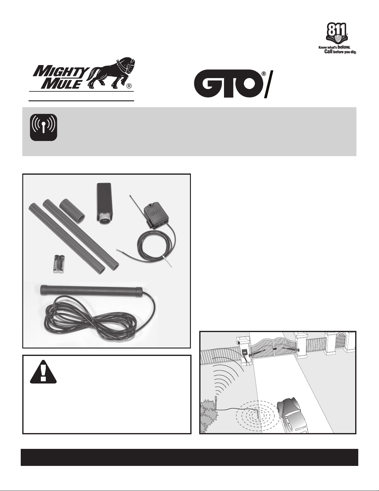
Kit Includes:
A. Transmitter Module/Cover
B. Sensor/Sensor Cable
C. Receiver (RB709U-NB required for some
C
gate openers)
D. Mounting Post (3 pieces)
E. 2 “AA” Batteries (Note: lithium-alkaline batteries
are recommended for extreme cold climates.)
How it Works:
The electromagnetic sensor detects vehicles in
motion and automatically activates your gate. This
“hands free” device allows friends, family, and
delivery personnel to exit your property without the
need of an Entry Transmitter, or you, to operate
the gate.
SYSTEMS
When a VEHICLE SENSOR is in
use, the automatic gate opener
could be activated by a child on
a bicycle, tricycle, or other metal
play equipment. DO NOT ALLOW
UNATTENDED CHILDREN OR
PETS NEAR YOUR AUTOMATED
GATE AT ANY TIME.
www.mightymule.com • www.gtoaccess.com
Printed in China for Gates at Open, LLC
©2010 GTO
rev. 10-04-10

This product and any accessory you purchase should only be installed on a gate opener
that meets the current UL325 safety standard. If you have a gate opener that is not listed
with the current standard, please contact the GTO sales department for consultation on a
gate opener that can meet your specific needs.
FCC WARNING: Changes or modifications to this unit not expressly approved by the party
responsible for compliance could void the user’s authority to operate the equipment.
NOTE: This equipment has been tested and found to comply with the limits for a Class B
digital device, pursuant to Part 15 of the FCC Rules. These limits are designed to provide
reasonable protection against harmful interference in a residential installation. This equipment
generates, uses and can radiate radio frequency energy and, if not installed and used in
accordance with the instructions, may cause harmful interference to radio communications.
However, there is no guarantee that interference will not occur in particular installations. If
this equipment does cause harmful interference to radio or television reception, which can
be determined by turning the equipment off and on, the user is encouraged to try to correct
the interference by one or more of the following measures: • Reorient or replace the receiver
antenna. • Increase the separation between the equipment and the receiver. • Connect the
equipment into an outlet on a circuit different from that to which the receiver is connected. •
Consult the dealer or an experienced radio/TV technician for help.
GTO Limited One Year Warranty
Gates That Open, LLC (GTO), gate openers and accessories are covered under warranty by the manufacturer against
defects in materials and manufacturer workmanship for a period of one (1) year from date of purchase, provided the
recommended installation procedures have been followed.
In the case of product failure due to defective material or manufacturer workmanship within the one (1) year warranty
period, the product will be repaired or replaced (at the manufacturer’s option) at no charge to the customer, if returned
freight prepaid to GTO, 3121 Hartsfield Road, Tallahassee, Florida, USA 32303. IMPORTANT: Call (800) 543-1236
for a Return Goods Authorization (RGA) number before returning accessory to factory. Products received at the
factory without an RGA number will not be accepted. Replacement or repaired parts are covered by this warranty for
the remainder of the one (1) year warranty period or six (6) months, whichever is greater. GTO will pay the shipping
charges (equal to United Parcel Service GROUND rate) for return to the owner of items repaired under warranty.
The manufacturer will not be responsible for any charges or damages incurred in the removal of the defective parts
for repair, or for the reinstallation of those parts after repair. This warranty shall be considered void if damage to the
product(s) was due to improper installation or use, connection to an improper power source, or if damage was caused
by electrical power surge or lightning, wind, fire, flood, insects or other natural agent.
After the one (1) year warranty period, GTO will make any necessary repairs for a nominal fee. Call GTO at (800) 5431236 for more information. This warranty gives you specific legal rights, and you may also have other rights which may
vary from state to state. This warranty is in lieu of all other warranties, expressed or implied. NOTE: Verification of the
warranty period requires copies of receipts or other proof of purchase. Please retain these records.
Gates That Open, LLC
3121 Hartseld Road • Tallahassee, Florida 32303
Sales: 1-800-543-GATE (4283) • Technical Support: 1-800-543-1236
www.gtoinc.com
rev. 10-04-10
Technical Support Hours: MON–FRI, 8:00 a.m.–7:00 p.m. (ET)
800/543-1236 • 850/575-4144
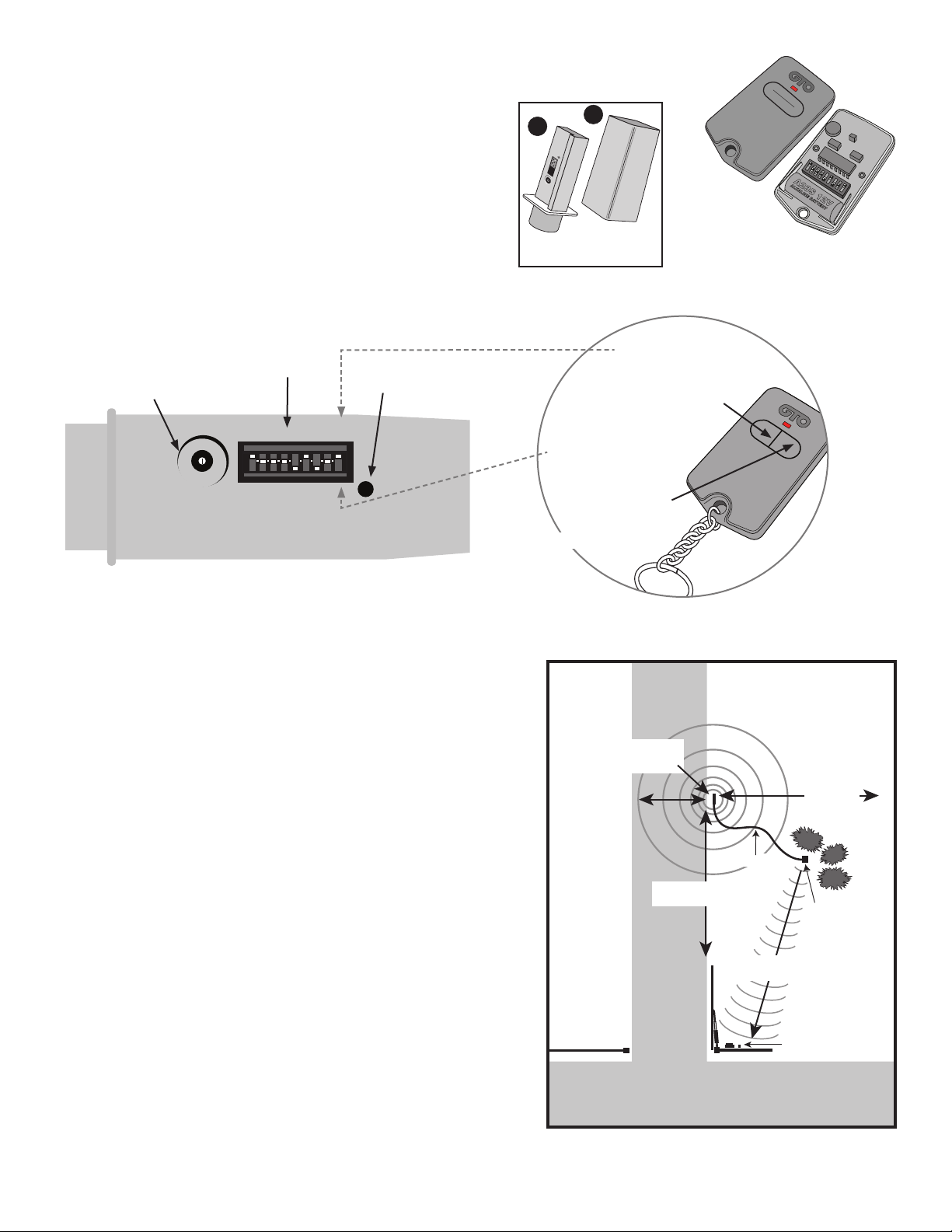
1. Program DIP Switch Settings
Step 1: Remove the cover from your gate opener Entry
Transmitter. Remove the cover from the Transmitter Module.
Step 2: You will change the DIP Switch settings on the
Transmitter Module to match those of your Entry Transmitter.
For Single Button Entry Transmitters, set the 9 DIP Switch
settings on the Transmitter Module to match the 9 DIP Switch
settings of the Entry Transmitter.
For Dual Button Entry Transmitters, set the first 8 DIP Switch
settings on the Transmitter Module to match the 8 DIP Switch
settings of the Entry Transmitter. The 9th DIP Switch setting
(Transmitter Module) will depend on which button you use to
operate the gate (see illustration).
Sensitivity
Adjustment
DIP Switches
Transmit Indicator
A
B
TRANSMITTING
1 2 3 4
TRANSMITTER CODE
SENSITIVITY
MIN MAX
Transmitter Module
and Cover
If you use this button
to operate gate, put
the 9th DIP Switch in
the “+” position
LED
1 2 3 4 5 6 7 8 9
+
0
–
A23S 12V
ALKALINE BATTERY
ECE
Single Button Entry Transmitter
SENSITIVITY
MIN MAX
TRANSMITTER
123456789
+
o
-
CODE
TRANSMITTING
If you use this button
to operate gate, put
the 9th DIP Switch
in the “0” position
WIRELESS VEHICLE SENSOR
GTO, Tallahassee, FL USA
Dual Button Entry Transmitter
Transmitter Module
2. Determine Location for Sensor and Transmitter Module
NOTE: Install Transmitter Module and Sensor on the same
side of the driveway as your automatic gate opener/receiver.
Placement of SENSOR:
• No more than 2 ft. from edge of driveway.
• At least 25 ft. from leading edge of open gate, roadways,
neighboring driveways, etc.
• Parallel to direction of the driveway.
Placement of TRANSMITTER MODULE:
• No more than 100 ft. from gate opener receiver.
• Within “line of sight” of the gate opener receiver.
• Away from lawn sprinklers (Transmitter Module is water resistant,
not waterproof).
• Away from the driveway edge so that vehicles are unlikely
to hit it.
For Optimum Performance:
• Install the Sensor as far away as possible from power
transformers, power lines, underground gas lines, and
telephone lines.
• Locate the Sensor away from general moving trafc to prevent
unwanted activation (the Sensor detects magnetic disturbances
caused by a vehicle’s mass and velocity).
• It is recommended that you run the Sensor Cable inside PVC
conduit to prevent accidental damage.
• Do not run Sensor Cable in conduit with other wires such as AC
power or other control wires.
• THE SENSOR CABLE MUST NOT BE SPLICED.
Sensor Range:
12' radius
Sensor Range distance is approximate and will vary
due to outside interference, vehicle mass, speed, etc.
DRIVEWAY
SENSOR:
up to 2' (max.)
from driveway
25' (min.)
from neighbor’s
driveway
Sensor Cable
25' (min.) from leading
edge of open gate
Transmitter Signal
ROADWAY
100' (max.)
Gate Opener
Receiver
TRANSMITTER
MODULE:
mounted away
from driveway edge
Wireless Vehicle Sensor rev. 02-18-12 1
 Loading...