

Page 1

TECHNICAL INFORMATION
T 980x and T 982x Dryers (US Models)
© 2010 Miele USA
Page 2

T 980x/T 982x
Technical Information
Table of Contents
A Warning and Safety Instructions ............................................................ 6
1 General Information ................................................................................... 6
2 Gas Dryers ................................................................................................ 6
3 Fire Danger Due To Excessive Lint ........................................................... 7
4 Restoring the Ground Connection after Dismantling the Front and Side
Panels ........................................................................................................ 7
B Modification History ................................................................................. 8
C Technical Data .......................................................................................... 9
D Layout of Electrical Components ......................................................... 10
1 T 980x ...................................................................................................... 10
2 T 982x ...................................................................................................... 11
010 Casing, Front Panel ............................................................................... 12
1 Technical Data ......................................................................................... 13
4 Service ..................................................................................................... 13
4.1 Lid Removal ................................................................................. 13
4.2 Removing the Front Panel ........................................................... 14
4.3 Side Panel Removal .................................................................... 14
020 Door, Lock .............................................................................................. 16
1 Technical Data ......................................................................................... 17
2 Function ................................................................................................... 17
2.1 Door Lock (A2) ............................................................................. 17
4 Service ..................................................................................................... 17
4.1 Door Removal .............................................................................. 17
4.2 Door Hinge Removal ................................................................... 18
4.3 Installing the Door Hinge ............................................................. 18
4.4 Removing the Door Lock ............................................................. 19
030 Drum, Rear Bearing, Residual Moisture Sensor, Heater Bank ........... 20
1 Technical Data ......................................................................................... 21
2 Function ................................................................................................... 22
2.1 No-Load Detection ....................................................................... 22
2.2 Residual Moisture Measurement ................................................. 22
2.3 Heater Control ............................................................................. 23
2.4 Temperature Limiter with Manual Reset (1F1, 2F1, 3F1) ............ 23
2.5 Drying Air NTC (1R30) ................................................................. 23
2.6 Heater Bank NTC (2R30) ............................................................ 23
2.7 Interior Drum Light (H3/6) ............................................................ 23
3 Fault Repair ............................................................................................. 23
3.1 Temperature Limiter with Manual Reset (F1) Has Tripped .......... 23
4 Service ..................................................................................................... 24
4.1 Heater Bank Removal (T 980x) ................................................... 24
4.2 Rear Bearing Removal ................................................................ 25
2
Page 3

T 980x/T 982x
Technical Information
4.3 Residual Moisture Sensor Removal ............................................ 27
4.4 Drum Light Removal .................................................................... 27
4.5 Lightbulb Replacement ................................................................ 27
031 Gas Heating (T 982x) .............................................................................. 28
1 Technical Data ......................................................................................... 29
2 Function ................................................................................................... 29
2.1 Gas Unit ....................................................................................... 29
4 Service ..................................................................................................... 33
4.1 Checking the Gas Burner ............................................................ 33
4.2 Removing the Gas Solenoid ........................................................ 35
4.3 Installing the Gas Solenoid Valve ................................................ 36
4.4 Removing the Gas Burner ........................................................... 38
4.5 Installing the Gas Burner ............................................................. 39
040 Motor, Fan ............................................................................................... 40
1 Technical Data ......................................................................................... 41
4 Service ..................................................................................................... 41
4.1 Fan Impeller Replacement ........................................................... 41
4.2 Motor Replacement ..................................................................... 43
050 Air Shield, Front Bearing ....................................................................... 44
1 Technical Data ......................................................................................... 45
3 Fault Repair ............................................................................................. 45
3.1 Vibration Noises from the Base Plate .......................................... 45
4 Service ..................................................................................................... 46
4.1 Air Shield Removal ...................................................................... 46
4.2 Felt Seal Replacement ................................................................ 47
090 Fascia Panel, Electronic ........................................................................ 49
1 Technical Data ......................................................................................... 50
2 Function ................................................................................................... 50
2.1 Reversing (Electric) (T 980x) ....................................................... 50
2.2 Reversing (Gas) (T 982x) ............................................................ 50
2.3 Dryer Function after a Power Interruption .................................... 50
2.4 Programming Functions ............................................................... 50
2.5 Residual Moisture Sensing .......................................................... 51
2.6 Overriding the Time Control ......................................................... 52
2.7 Insufficient Air Detection .............................................................. 52
2.8 Operating Hours Counter ............................................................. 52
2.9 Low-Voltage Detection ................................................................. 52
3 Fault Repair ............................................................................................. 53
3.1 “End” LED Is Steadily Lit .............................................................. 53
3.2 “Check Filter/Vent” LED Is Steadily Lit ........................................ 53
3.3 “Check Filter/Vent” LED Flashes Rapidly .................................... 54
3.4 “Rotary Iron” LED Flashes ........................................................... 54
3.5 “Hand Iron” LED Flashes ............................................................. 54
3.6 All Program LEDs Flash .............................................................. 55
3.7 F0: No Fault ................................................................................. 55
3.8 F1: Short Circuit in Heater Bank NTC (2R30) .............................. 55
3
Page 4

T 980x/T 982x
Technical Information
3.9 F2: Open Circuit in Heater Bank NTC (2R30) ............................. 55
3.10 F3: Drying Air NTC (1R30) Short Circuit ...................................... 56
3.11 F4: Drying Air NTC (1R30) Open Circuit ..................................... 57
3.12 F50: Motor Stalls and Heater Is On for 3 Seconds ...................... 57
3.13 F55: Overriding Time Limit Exceeded ......................................... 57
3.14 F66: Air Leakage ......................................................................... 58
3.15 F98: No Gas Ignition (T 982x only) .............................................. 58
3.16 Laundry Is Overdried/F55 (Overriding Time Limit Exceeded) ..... 59
3.17 Dryer Shuts Itself Off ................................................................... 59
4 Service ..................................................................................................... 60
4.1 Programming Mode Summary ..................................................... 60
4.2 Activating/Deactivating the Demonstration Mode ........................ 62
4.3 Service Mode Summary .............................................................. 62
4.4 Removing the Fascia, Electronic and Electronic Support Panel .. 64
100 Electrical System ................................................................................... 66
1 Technical Data ......................................................................................... 67
4 Service ..................................................................................................... 67
4.1 Fuse Replacement (T 980x only) ................................................. 67
4.2 Heater Relay Removal ................................................................. 67
List of Figures
Figure D-1: T 980x Component Layout ........................................................................... 10
Figure D-2: T 982x Component Layout ........................................................................... 11
Figure 010-1: Lid Removal .............................................................................................. 13
Figure 010-2: Front Panel Removal ................................................................................ 14
Figure 010-3: Side Panel Removal ................................................................................. 15
Figure 020-1: Door Removal ........................................................................................... 18
Figure 020-2: Door Lock Removal .................................................................................. 19
Figure 030-1: Heater Bank Removal ............................................................................... 25
Figure 030-2: Bearing Housing Attachment .................................................................... 26
Figure 030-3: Rear Bearing ............................................................................................. 26
Figure 031-1: Gas Ignition Schematic ............................................................................. 30
Figure 031-2: Onset of Drying Process, Before Gas Starts to Flow ................................ 30
Figure 031-3: Drying Process, After Gas Has Started to Flow ........................................ 31
Figure 031-4: Drying Process, Flowing Gas Ignites the Flame ....................................... 31
Figure 031-5: Drying Process after Flame Has Gone Out .............................................. 32
Figure 031-6: Port for Measuring Jet Pressure ............................................................... 34
Figure 031-7: Gas Regulation Valve ............................................................................... 35
Figure 031-8: Disconnecting the Gas Regulation Valve ................................................. 36
Figure 031-9: Attaching the Gas Connecting Line to the Gas Regulation Valve ............ 36
Figure 031-10: Tightening the Gas Regulation Valve ..................................................... 37
Figure 031-11: Gas Regulation Valve ............................................................................. 37
Figure 031-12: Gas Regulation Valve ............................................................................. 38
Figure 031-13: Gas Regulation Valve ............................................................................. 39
Figure 040-1: Fan Impeller Removal ............................................................................... 42
Figure 050-1: Sealing Strip Installation ........................................................................... 45
4
Page 5

T 980x/T 982x
Technical Information
Figure 050-2: Air Shield Removal ................................................................................... 46
Figure 050-3: Felt Seal Installation ................................................................................. 47
Figure 090-1: Removing the Fascia, Electronic, and Electronic Support Panel .............. 65
Figure 100-1: Fuse Replacement .................................................................................... 67
List of Tables
Table C-1: General Technical Data ................................................................................... 9
Table 010-1: Casing Technical Data ............................................................................... 13
Table 020-1: Door Technical Data .................................................................................. 17
Table 030-1: Drum Data .................................................................................................. 21
Table 030-2: Heater Data ................................................................................................ 21
Table 030-3: Heater Bank and Drying Air NTC Resistance Values ................................ 22
Table 031-1: Gas Heating Data ...................................................................................... 29
Table 040-1: Fan and Motor Data ................................................................................... 41
Table 050-1: Air Shield Data ........................................................................................... 45
Table 090-1: Technical Data ........................................................................................... 50
Table 090-2: Residual Moisture, Delicates ..................................................................... 51
Table 090-3: Values for Low-Voltage Detection .............................................................. 52
Table 090-4: Programming Mode Summary ................................................................... 61
Table 090-5: Service Mode Summary ............................................................................. 64
Table 100-1: Electrical System Data ............................................................................... 67
5
Page 6

Technical Information
A Warning and Safety Instructions
1 General Information
Danger!
Danger of high voltages when working on small components.
In a single-board control, as in this appliance's electronic (EPWL 3xx),
there is no structural galvanic potential disconnection to the power supply.
Therefore, be careful when working on small components, as they may
be carrying voltage if the dryer is not disconnected completely from its
power supply.
Components with sharp edges may stick out. Wear protective gloves and
goggles and use edge shields to prevent cuts by sharp-edged components.
Note:
All repairs should be performed by a trained technician in strict
accordance with national, state and local codes. Any repairs or
maintenance performed by unqualified personnel could be dangerous.
When servicing, modifying, testing or maintaining appliances, all
applicable laws, regulations and accident prevention guidelines must be
observed.
T 980x/T 982x
After work has been completed, a visual as well as an operational check
should always be performed.
After work has been completed, do a touch current measurement on
machines with a ground connection on all accessible conductive parts
that are not grounded.
Before starting any service work, disconnect the dryer from its power
source. Even with the appliance switched off, voltage may exist on some
components.
2 Gas Dryers
Warning!
Before starting any service or repair work, it is essential to disconnect the
dryer from its gas supply.
Service work may only be performed by a technician trained in gas
technology, and in keeping with all relevant safety standards.
Prior to the start of service work, check all gas lines and components to
make sure that they are sealed.
If there is a gas odor, shut the gas tap. Avoid sparks or any fire source,
and air out all rooms.
6
Page 7

T 980x/T 982x
Technical Information
3 Fire Danger Due To Excessive Lint
Danger!
The dryer must not be operated if there are leaks in the air shield, such as
those caused by a defective seal.
If the dryer is operated regardless of these leaks, this will result in heavy
lint in the appliance interior. Moisture can make this excessive lint soggy,
which will lead to electrical short circuits and possibly fire.
Indications of excessive lint: a poorly maintained dryer, long running time
(fixed maximum time has been exceeded), water under the fascia panel.
Remedy:
- Remove all lint from the dryer.
- Find and repair leaks.
4 Restoring the Ground Connection after Dismantling the
Front and Side Panels
The ground connection for laundry-care appliances is established via
screws: raised-head screws with teeth or serrated washers underneath
connect the ground lead to the interference-suppression filter, the front
panel, the side panels and the housing frame. These screws are different
from the rest of the appliance screws in their diameter, type of thread, and
type and material of the washer.
The ground connection is made only if the ground screws are screwed
into their correct positions during reassembly.
When dismantling the front and side panels, mark the positions of the
ground screws. During reassembly, screw the ground screws into these
same positions.
To check the proper screw positions, measure the resistance of the
ground connection loop.
7
Page 8
Technical Information
B Modification History
When Who What
6/3/2010 Jessica Naples T 9802 added (reflected in “T 980x”)
8/27/2009 Jessica Naples Conversion for Website
3/11/2009 Liane Westerhelweg Version 5
5/16/2008 Liane Westerhelweg Version 4
5/14/2008 Liane Westerhelweg Version 3
12/8/2006 Olaf Meyer zu Drewer Version 2
11/30/2006 Olaf Meyer zu Drewer Initial compilation
T 980x/T 982x
8
Page 9
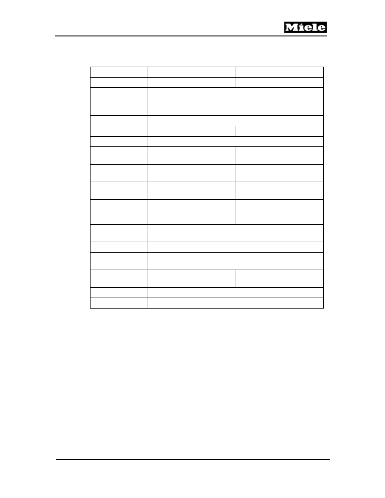
T 980x/T 982x
C Technical Data
T 980x T 982x
Dimensions
Shipping
dimensions
Shipping weight
Required voltage
Frequency
Connected load
(electric)
Natural gas output
Natural gas - net
pressure
Exhaust pipe
(vented dryers
only)
Washer/dryer
stack
Under-counter
Washer/dryer
stand
Liquid propane
conversion
PC interface
RemoteVision
Table C-1: General Technical Data
Electric Heating Gas Heating
2NAC 240V (208V) 1NAC 120V
Technical Information
Height x width x depth: 39” x 27” x 30”
Height x width x depth: 42” x 30” x 32”
Approx. 165 lbs
60Hz
5.8kW 0.3kW
N/A 1076 BTU/ft3
N/A Supply pressure 4oz/in2
N/A
Optional
N/A Optional
Compatible, optional accessory
Connecting pipe nominal
diameter 4”
No
No
Yes
9
Page 10
Technical Information
D Layout of Electrical Components
1 T 980x
T 980x/T 982x
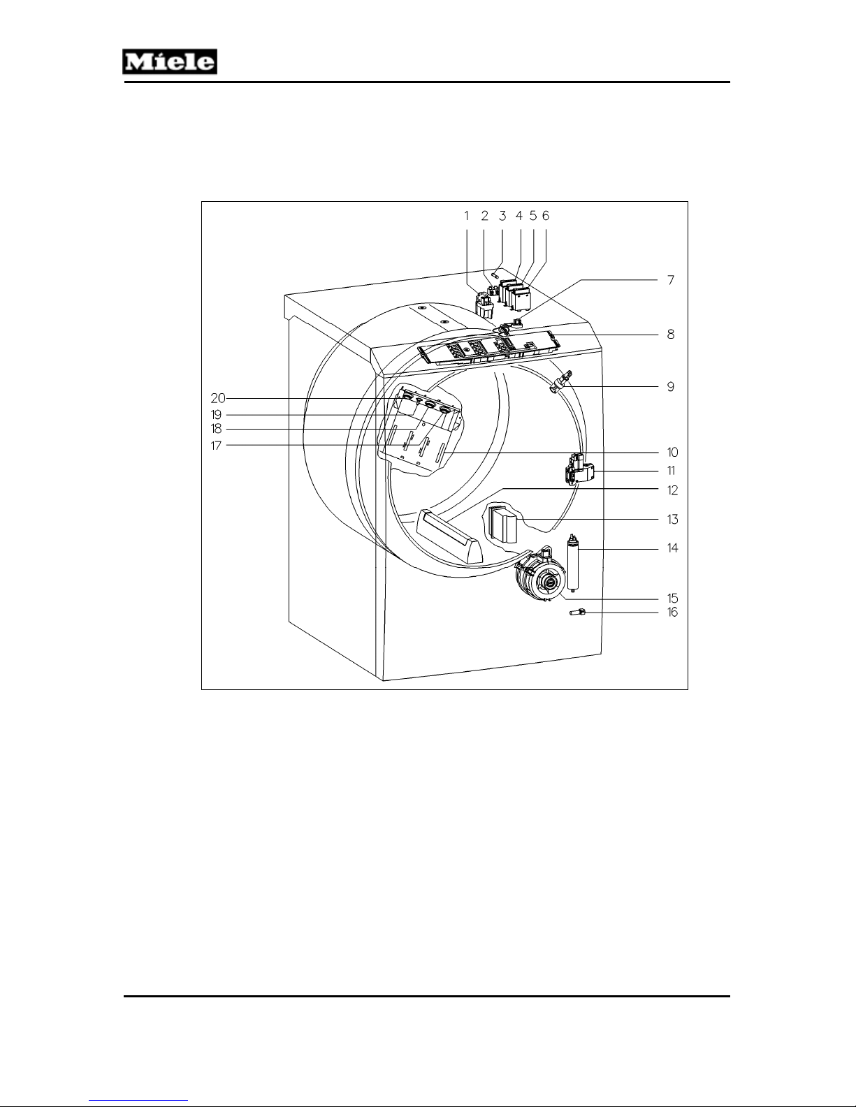
Figure D-1: T 980x Component Layout
1 (Z/1) Interference suppression capacitor 11 (A2) Door lock
2 (X3/1) Terminal block 12 (B3/1) Residual moisture sensor - Drum rib
3 (F2) Fuse 13 (WLAN) RemoteVision (optional)
4 (1K1/1) Heater relay 14 (C5) Motor capacitor
5 (2K1/1) Heater relay 15 (M5) Motor
6 (3K1/1) Heater relay 16 (1R30) Drying air NTC
7 (B3/1) Residual moisture sensor 17 (3F1) Temperature limiter w/manual reset
8 (1N1) Electronic (EPWL) 18 (2F1) Temperature limiter w/manual reset
9 (H3/6) Drum light 19 (2R30) Heater bank NTC
10 (R1, R2, R3) Heater bank 20 (1F1) Temperature limiter w/manual reset
10
Page 11
T 980x/T 982x
2 T 982x
Technical Information
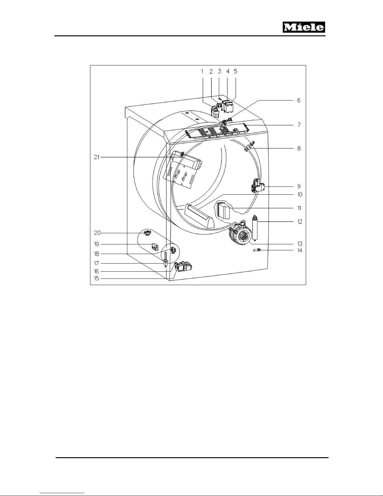
Figure D-2: T 982x Component Layout
1 (Z/1) Interference suppression capacitor 12 (C5) Motor capacitor
2 (X3/1) Terminal block 13 (M5) Motor
3 (F2) Fuse 14 (1R30) Drying air NTC
4 (1K1/1) Heater relay 15 (Y57/1) Gas solenoid
5 (2K1/1) Heater relay 16 (Y57/2) Gas solenoid
6 (B3/1) Residual moisture sensor 17 (E1/1) Igniter electrode
7 (1N1) Electronic (EPWL)
8 (H3/6) Drum light 19 (B1/16)
9 (A2) Door lock 20 (1F1) Temperature limiter w/manual reset
10 (B3/1) Residual moisture sensor - Drum rib 21 (2R30) Heater bank NTC
11 (WLAN) RemoteVision (optional)
18 (2F1) Temperature limiter flame flashback
w/manual reset
Flame sensor (radiant output sensor)
11
Page 12
Technical Information
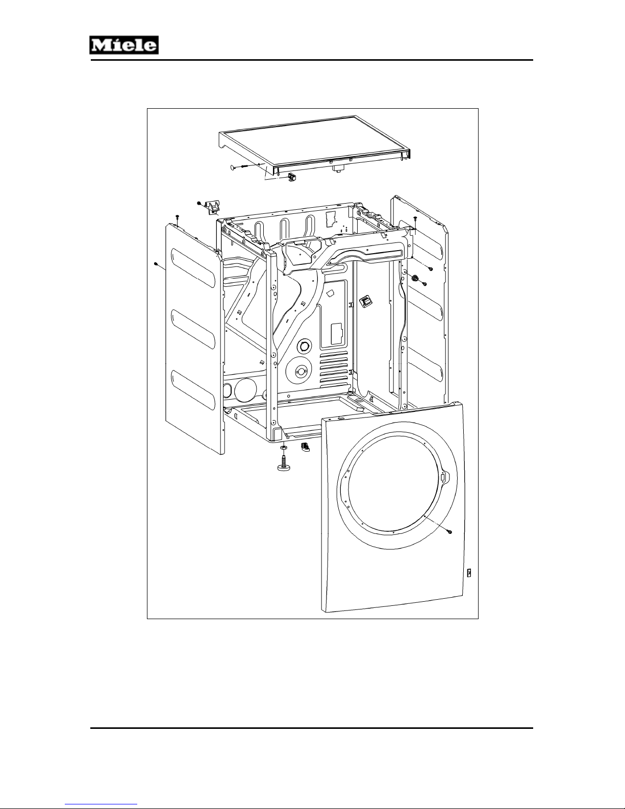
010 Casing, Front Panel
T 980x/T 982x
12
Page 13

T 980x/T 982x
1 Technical Data
Design
Table 010-1: Casing Technical Data
Upright, frame construction, side walls
embossed for reinforcement
4 Service
4.1 Lid Removal
1. Disconnect the machine from the power supply.
2. Remove the screw caps on the sides. See Figure 010-1.
3. Loosen the T20 screws a maximum of 5 turns. Do not unscrew the
screws completely.
4. Press in on the screws.
5. Lift the lid at the front and slide it back to release it from its retainers.
Take the lid off.
Technical Information
Figure 010-1: Lid Removal
13
Page 14
Technical Information
4.2 Removing the Front Panel
1. Disconnect the machine from the power supply.
2. Remove the dryer lid; refer to Section 010-4.1.
3. Remove the fascia, the electronic, and the electronic's support panel; refer
to Section 090-4.4.
4. Open the door.
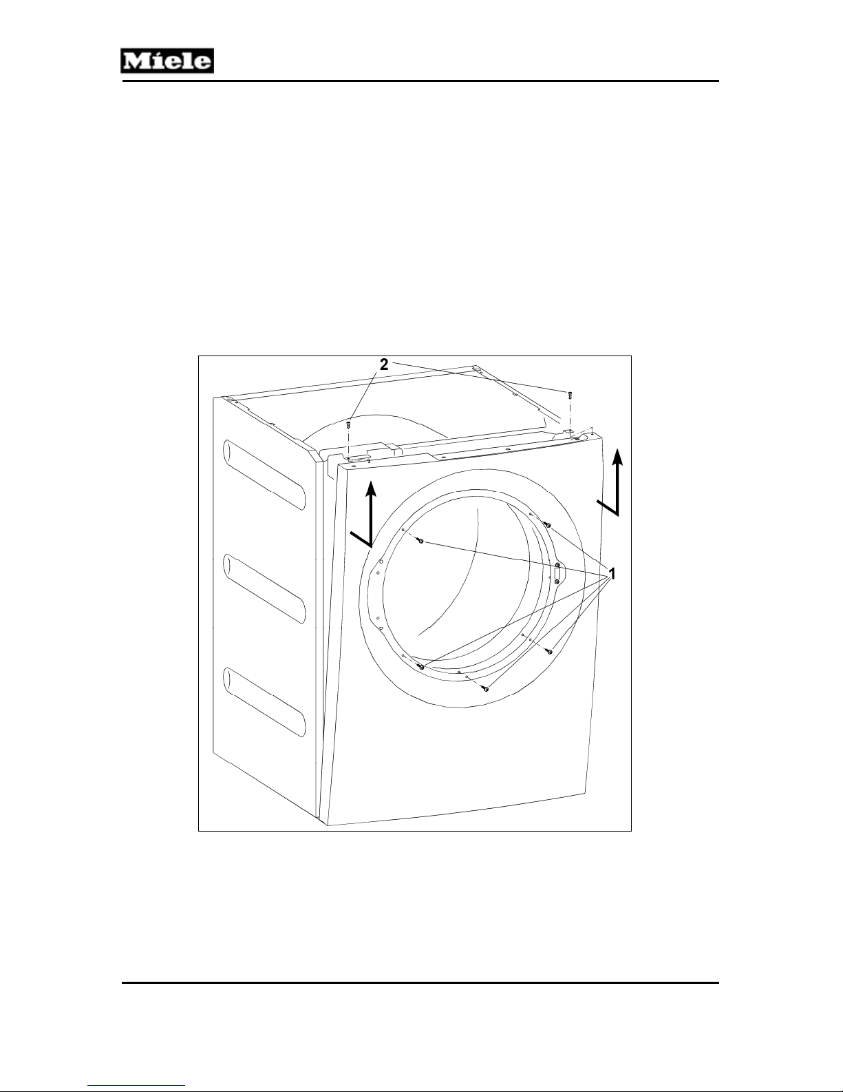
5. Remove the five T20 screws securing the front of the front panel. See
Figure 010-2, Item 1.
6. Close the door.
7. Remove the two T20 screws securing the top of the front panel. See
Figure 010-2, Item 2.
8. Disconnect the door lock Molex connection.
9. Pull the front panel upwards to remove.
T 980x/T 982x
Figure 010-2: Front Panel Removal
4.3 Side Panel Removal
1. Disconnect the machine from the power supply.
2. Remove the lid; refer to Section 010-4.1.
3. Remove the front panel; refer to Section 010-4.2.
14
Page 15
T 980x/T 982x
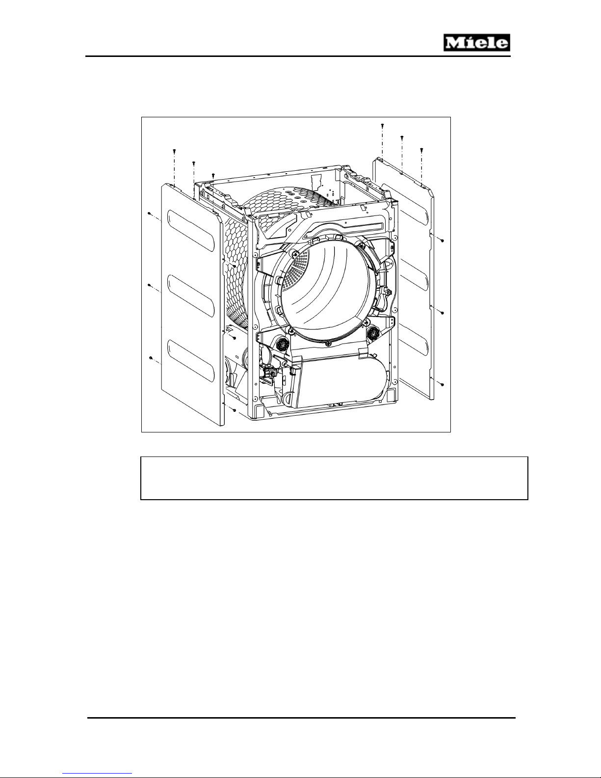
4. Remove the side panel retaining screws (nine T20s per panel). See
5. Take the side panel(s) off.
Technical Information
Figure 010-3.
Figure 010-3: Side Panel Removal
Note:
When re-installing the side panels, ensure that the screws with serrated
washers (ground screws) are installed in the correct positions.
15
Page 16
Technical Information
020 Door, Lock
T 980x/T 982x
16
Page 17
T 980x/T 982x
1 Technical Data
Door
Lock
Table 020-1: Door Technical Data
2 Function
2.1 Door Lock (A2)
Pull the door open.
An open door is registered by a microswitch in the door lock
(drum door open = contact open).
4 Service
4.1 Door Removal
1. Disconnect the appliance from the power supply.
2. Take off the front panel; refer to Section 010-4.2.
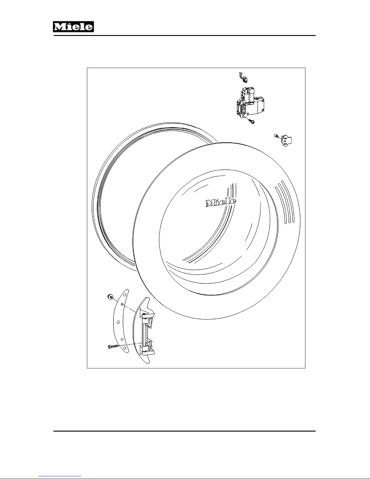
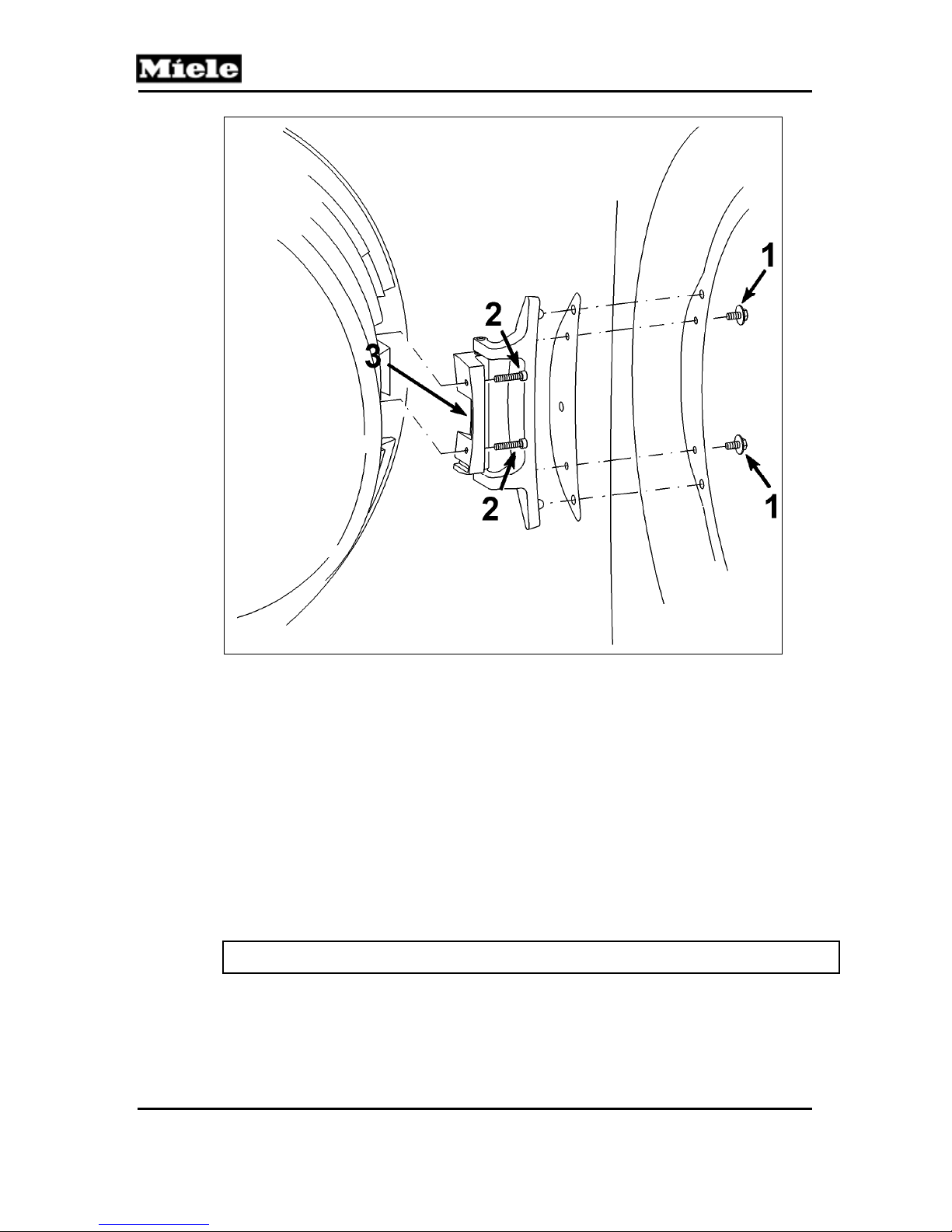
3. Turn the front panel around and remove the two locknuts (Figure 020-1,
Item 1) with an 8-millimeter nut driver or wrench.
4. Carefully separate the door from the front panel.
Technical Information
Porthole door. Door hinge is on the left
and cannot be reversed.
Manual pull-open lock.
Door lock contact switch (A2). Drum
door open = contact open.
17
Page 18
Technical Information
T 980x/T 982x
Figure 020-1: Door Removal
4.2 Door Hinge Removal
1. Disconnect the appliance from the power supply.
2. Remove the door; refer to Section 020-4.1.
3. Turn the door over; lay it on a soft mat or cloth so that the door glass
does not get damaged.
4. Remove the two T20 bolts securing the hinge to the door (Figure 020-1, Item 2).
5. Insert a flathead screwdriver under the bottom of the hinge and lift up to
release the hinge from its base on the door (Figure 020-1, Item 3).
4.3 Installing the Door Hinge
1. Open the hinge and slide it back onto its base.
2. Close the hinge and re-secure it with the two T20 bolts.
Note: Make sure that the hinge lines up with the welded seam of the door seal.
18
Page 19
T 980x/T 982x
4.4 Removing the Door Lock
1. Disconnect the appliance from the power supply.
2. Take off the front panel; refer to Section 010-4.2.
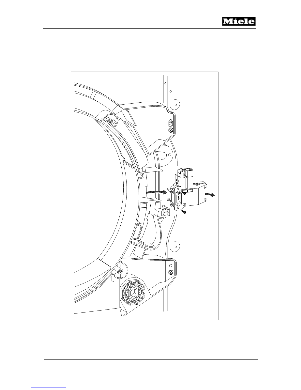
3. Remove the two T20 screws securing the door lock to the front panel.
See Figure 020-2.
Technical Information
Figure 020-2: Door Lock Removal
19
Page 20
T 980x/T 982x
Technical Information
030 Drum, Rear Bearing, Residual Moisture Sensor,
Heater Bank
20
Page 21
T 980x/T 982x
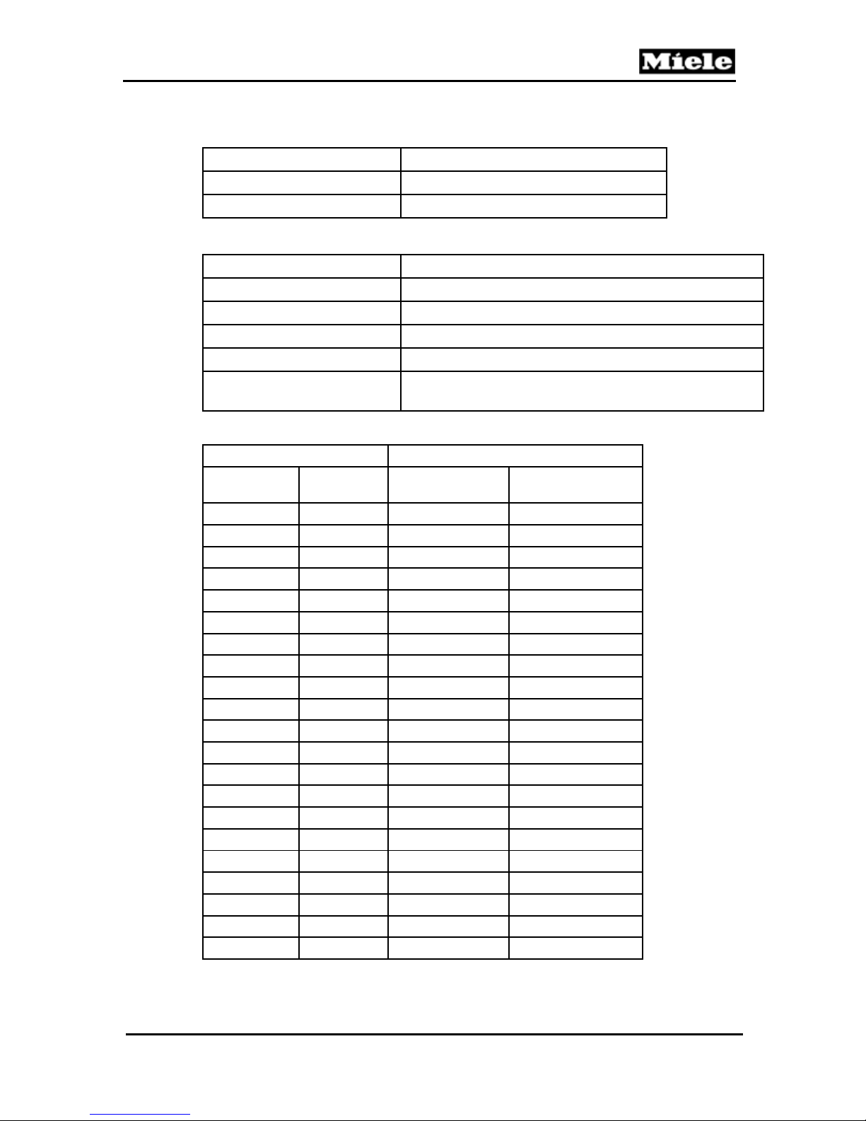
1 Technical Data
Maximum load
Drum volume
Drum speed
Table 030-1: Drum Data
Heating mode
Heater type
Heater output
Temperature sensor
Temperature limiter
Drum light (H3/6)
Table 030-2: Heater Data
Temperature Resistance (kΩ)
°F °C
32 0 340 38.0
41 5 261 29.7
50 10 203 23.4
59 15 159 18.6
68 20 126 14.9
77 25 100 12.0
86 30 80.2 9.73
95 35 64.8 7.96
104 40 52.7 6.55
113 45 43.1 5.42
122 50 35.5 4.52
131 55 29.4 3.78
140 60 24.5 3.19
149 65 20.5 2.70
158 70 17.3 2.29
167 75 14.6 1.96
176 80 12.5 1.68
185 85 10.6 1.45
194 90 9.13 1.25
199 93 8.34 1.15
203 95 7.86 1.09
Technical Information
17.6 lbs (8 kg)
48 gal (180L)
48 rpm
Electric; for gas, refer to Table 031-1.
Duct heater bank (R1, R2, R3); 3-filament
5.2kW (1.90kW, 1.70kW, 1.60kW)
Heater bank NTC (2R30)
3 x 3/4“ temperature limiter (F1) with manual reset, 16A
E 14 bayonet closure, activation via relay on the
electronic (EPWL). USA: 120V, 15W
Heater bank NTC
(2R30)
Drying air NTC
(1R30)
21
Page 22
Technical Information
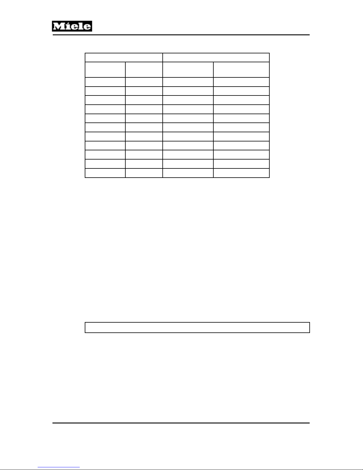
Temperature Resistance (kΩ)
°F °C
212 100 6.80 1.06
230 110 5.14 0.73
248 120 3.95 0.569
266 130 3.07 0.449
284 140 2.41 0.358
302 150 1.92 0.289
320 160 1.55 N/A
338 170 1.26 N/A
356 180 1.03 N/A
374 190 0.852 N/A
392 200 0.710 N/A
Table 030-3: Heater Bank and Drying Air NTC Resistance Values
Heater bank NTC
(2R30)
2 Function
2.1 No-Load Detection
Only in residual moisture programs.
Senses no load or very dry laundry.
Residual moisture sensor B3/1 detects the electrical resistance of the
laundry load; if this resistance is very high, it means that the laundry is dry
or that there is no load in the drum. If this is the case, then the drying
cycle will stop within 30 seconds of starting and the message Check load
will be displayed.
2.2 Residual Moisture Measurement
Residual moisture is calculated based on the electrical resistance of the
damp laundry, which is measured by a sensor between a drum rib and the
drum casing.
T 980x/T 982x
Drying air NTC
(1R30)
Note: Only one rib is used for this measurement.
The value of this electrical resistance depends on the type of laundry, the
degree of moisture, the laundry load (weight) and the drum's rotating angle
(centrifugal force, rib contact).
22
Page 23
T 980x/T 982x
Technical Information
2.3 Heater Control
Safety function:
If the drying air NTC (1R30) is defective, then the heater will not be switched on.
The heater is switched off as soon as the heater relay has been running for
more than 5 seconds without the motor relay being activated as well.
Heater reactivation is delayed by 10 seconds; the auxiliary heater is switched off
before, during and after a reversing pause.
2.4 Temperature Limiter with Manual Reset (1F1, 2F1, 3F1)
Three closed 3/4-inch temperature limiters, with manual reset via pushbutton,
are on the heater bank (T 980x only).
2.5 Drying Air NTC (1R30)
If the drying air NTC detects temperatures lower than 5°F (-15°C) or higher
than 320°F (160°C), then this NTC is defective.
2.6 Heater Bank NTC (2R30)
An open circuit in the heater bank NTC can only be detected at temperatures
higher than 57°F (14°C). Since lower temperatures can exist during dryer
operation, sensor readings will be evaluated only after the heater has been
running for at least 1 minute.
Note: If the heater is defective, fault F4 (heater bank NTC) is issued.
If the heater bank NTC has a short circuit (corresponding to 482°F), the
heater will be switched off immediately.
2.7 Interior Drum Light (H3/6)
Time controlled: 1 second after the door is opened.
Shutoff delay: 5 minutes.
The light is always switched off when the door is closed.
3 Fault Repair
3.1 Temperature Limiter with Manual Reset (F1) Has Tripped
Symptom:
The temperature limiter has tripped repeatedly.
Cause:
Clogged lint screen.
Remedy:
Clean the lint screen.
23
Page 24

Technical Information
Cause:
Clogged air duct vents.
Remedy:
Clean the air duct openings.
Cause:
Clogged air vents/exhaust vents.
Remedy:
Clean the air vents/exhaust vents.
Cause:
Drum is sluggish.
Remedy:
1. Check the front bearing seals (front and back needle felting) for correct
position.
2. Check and adjust the bearing of the front support rollers.
Cause:
Intermediate (small) drive is faulty.
Remedy:
Check the intermediate drive for dirt deposits, wear and tear, and tension
(also check the tension spring).
T 980x/T 982x
Cause:
Drum belt is faulty.
Remedy:
Check the drum belt for dirt deposits, wear and tear, and tension (tension
spring on intermediate drive).
4 Service
4.1 Heater Bank Removal (T 980x)
1. Disconnect the appliance from the power supply.
2. Remove the dryer lid; refer to Section 010-4.1.
3. Remove the front panel; refer to Section 010-4.2.
4. Remove the right side panel; refer to Section 010-4.3.
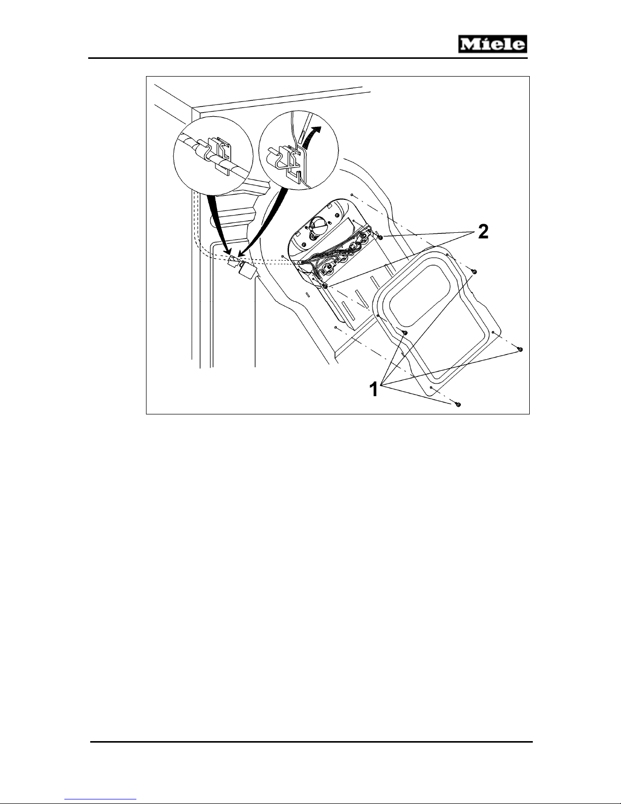
5. Remove the four T20 screws securing the service panel door at the back
of the dryer (Figure 030-1, Item 1).
6. Remove the wiring harness from the cable clip inside the rear panel of the
appliance.
7. Disconnect all electrical connections.
8. Remove the two T20s securing the heater bank (Figure 030-1, Item 2)
and detach the heater bank to remove.
24
Page 25
T 980x/T 982x
Technical Information
Figure 030-1: Heater Bank Removal
4.2 Rear Bearing Removal
1. Disconnect the appliance from the power supply.
2. Remove the dryer lid; refer to Section 010-4.1.
3. Remove the front panel; refer to Section 010-4.2.
4. Remove the right side panel; refer to Section 010-4.3.
5. Take the drum belt off of the intermediate (small) drive.
6. In electric dryers: Detach the heater bank and move it to the side
(without removing it); see Section 030-4.1.
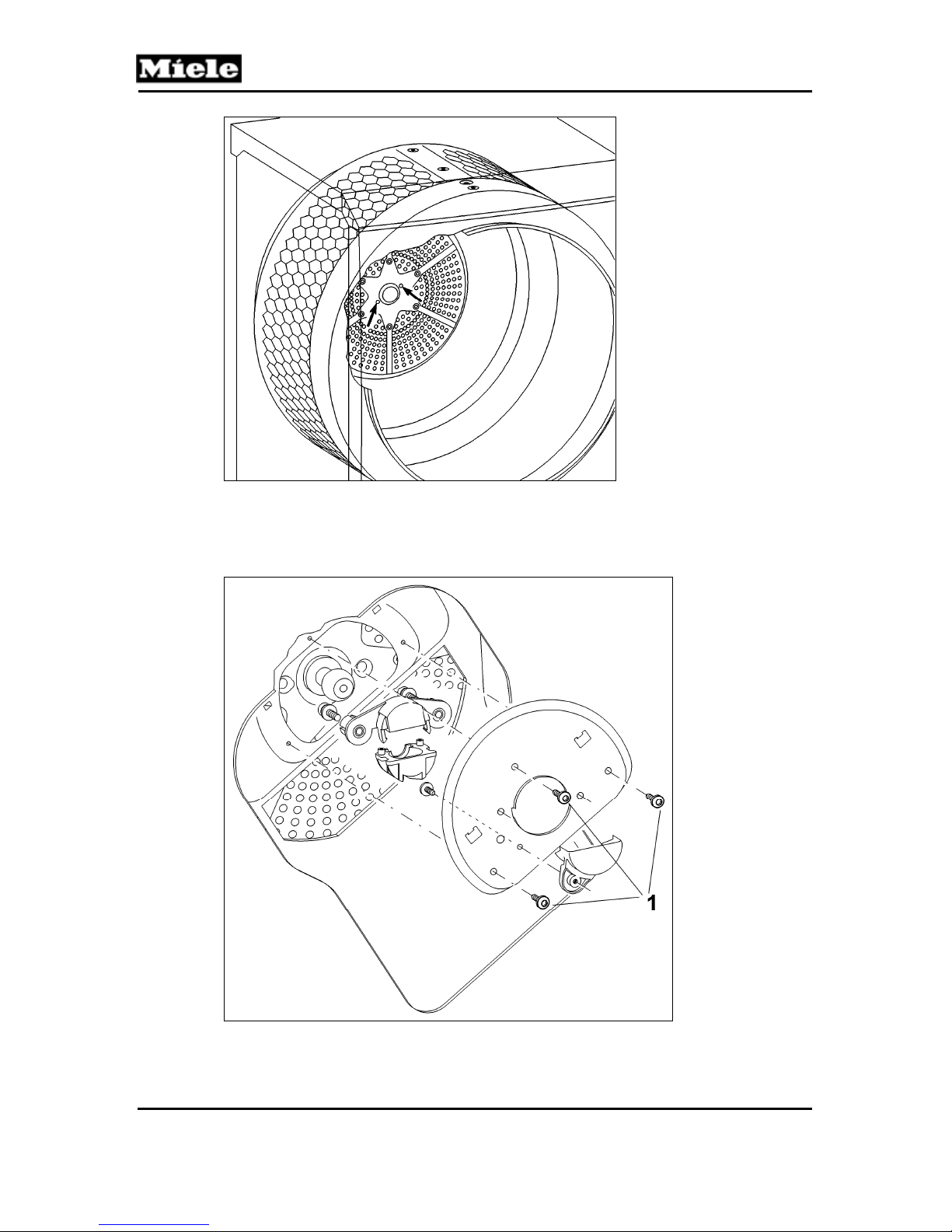
7. Unscrew the bearing housing attachment (two T30s; see arrows, Figure 030-2).
25
Page 26
Technical Information
T 980x/T 982x
Figure 030-2: Bearing Housing Attachment
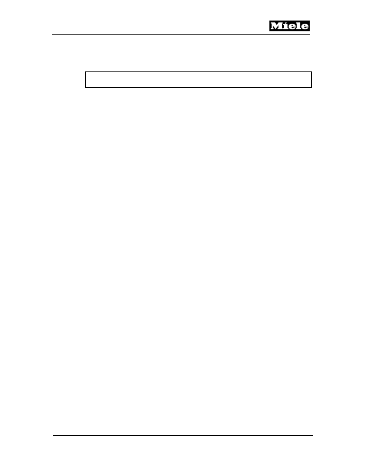
8. Remove the three T20 screws securing the bearing cover at the rear of
the machine; see Figure 030-3, Item 1.
9. Unlock the rear bearing and take it off.
Figure 030-3: Rear Bearing
26
Page 27
T 980x/T 982x
4.3 Residual Moisture Sensor Removal
1. Disconnect the appliance from the power supply.
2. Remove the dryer lid; refer to Section 010-4.1.
Note:
The residual moisture sensor is located at Figure D-1, Item 7.
3. Unhook the spring.
4. Press up on the plastic support to free it from the retainers on the cable
guide on the side panel.
5. Disconnect the two-pin Molex connector from the electronic, as well as
the ground wire from the rear panel of the appliance.
4.4 Drum Light Removal
1. Disconnect the machine from the power supply.
2. Remove the front panel. See Section 010-4.2.
3. Twist the light half a turn (180° counterclockwise) and remove it from its
housing on the air shield (see Figure D-1, Item 9, for location).
4. Free the two-pin wiring harness from the zip tie on the air shield (cut the
zip tie, if necessary) and the cable guide on the metal support plate.
4.5 Lightbulb Replacement
See the operating manual.
Technical Information
27
Page 28
Technical Information
031 Gas Heating (T 982x)
T 980x/T 982x
28
Page 29
T 980x/T 982x
1 Technical Data
Heating mode
Gas burner
Natural-gas version output
Temperature sensor
Temperature limiter
Safety time; refer to
Section 031-2.1.3
Table 031-1: Gas Heating Data
2 Function
2.1 Gas Unit
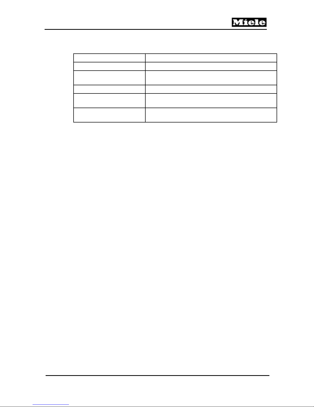
2.1.1 Gas Solenoid Valve (Y57)
In gas dryers, gas solenoid valve Y57 is activated via heater relays 1K1/1
and 2K1/1.
Gas solenoid valve Y57 consists of gas solenoid valves Y57/1 and Y57/2.
Gas solenoid valve Y57/1, in turn, consists of a maintaining coil and a
booster coil.
Gas solenoid valve Y57 only opens when both solenoid valves (Y57/1
and Y57/2) are opened.
Gas solenoid valve Y57/1 only opens when its maintaining and booster
coils carry voltage.
Once gas solenoid valve Y57/1 is open, it remains in this state as long as
its maintaining coil carries voltage.
Technical Information
Gas; for electric, refer to Table 030-2.
Gas burner, pipe configuration, 5.7kW. Model: Venturi
5.4kW ANSI Gas A, 1076 BTU/ft
Heater bank NTC (2R30)
Two 3/4” bi-metal temperature limiters (1F1, 2F1) with
manual reset, 16A, 248°F/212°F ± 5 K
≤ 90 seconds
3
29
Page 30
Technical Information
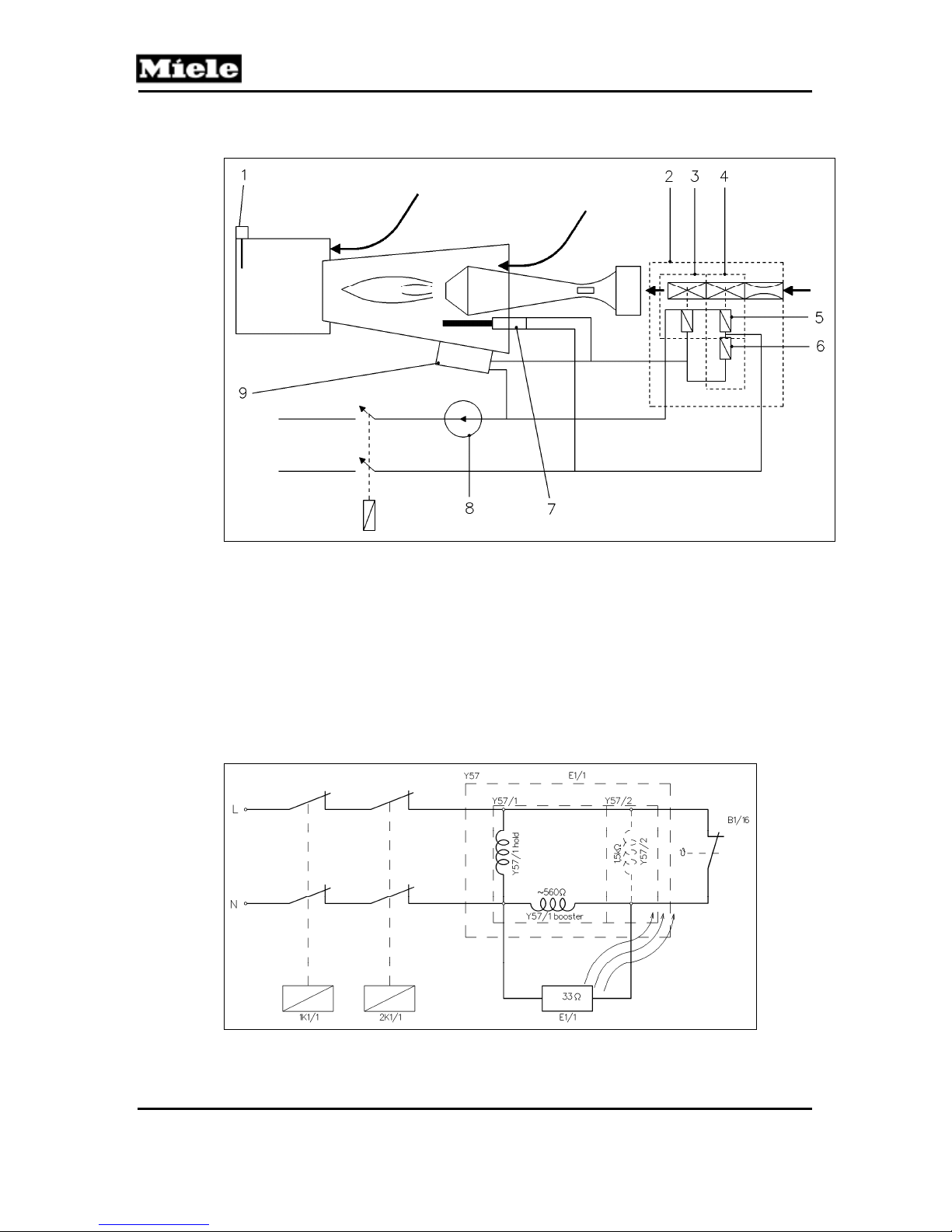
2.1.2 Gas Ignition
T 980x/T 982x
Figure 031-1: Gas Ignition Schematic
1 NTC heating (1R30, 2R30) in heating duct
2 Gas solenoid valve Y57
3 Gas solenoid valve Y57/2
4 Gas solenoid valve Y57/1
5 Maintaining coil for gas solenoid valve Y57/1
6 Booster coil for gas solenoid valve Y57/1
7 Igniter E1/1
8 Temperature limiter (1F1, 2F1)
9 Flame sensor (radiance sensor B1/16)
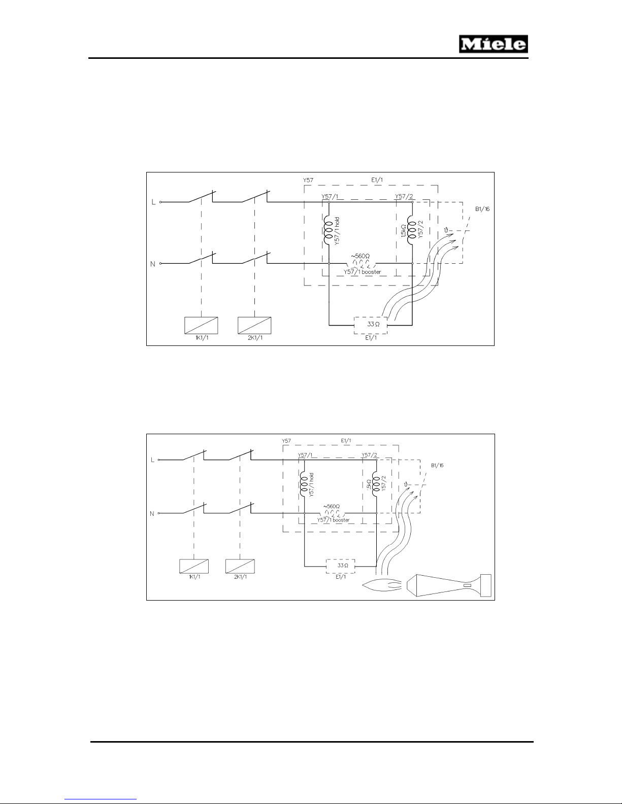
Figure 031-2: Onset of Drying Process, Before Gas Starts to Flow
30
Page 31
T 980x/T 982x
At the start of the drying process, flame sensor B1/16 is in a cool state and is
closed. Gas solenoid valve Y57/2 is not carrying voltage and is therefore
closed. At the demand for heating, both heater relays 1K1/1 and 2K1/1 close.
Maintaining and booster coils of gas solenoid valve Y57/1 carry voltage so
gas solenoid valve Y57/1 opens; igniter electrode E1/1 receives voltage and
slowly starts to glow. Since both gas solenoid valves Y57/2 and Y57/1
switched in sequence are not open, gas does not yet flow.
Technical Information
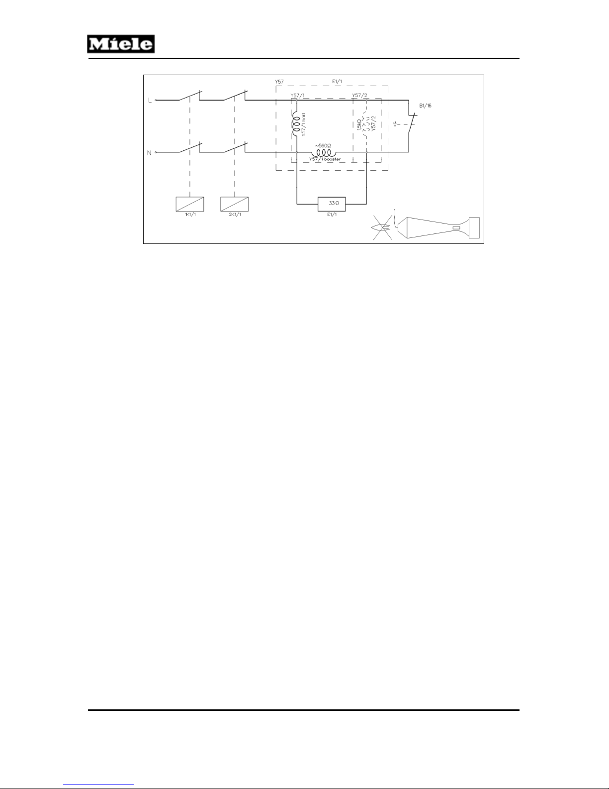
Figure 031-3: Drying Process, After Gas Has Started to Flow
Once the heat radiance on flame sensor B1/16 is strong enough, the thermostat
opens. Now igniter electrode E1/1 no longer carries voltage. However, now gas
solenoid valve Y57/2 is receiving voltage (via low-ohmic igniter electrode E1/1), so
it opens. Since gas solenoid valve Y57/1 is still open via its maintaining coil, gas
now flows into the burner and ignites at red-hot igniter electrode E1/1.
Figure 031-4: Drying Process, Flowing Gas Ignites the Flame
The flame is on. The flame keeps flame sensor B1/16 open and at temperature.
31
Page 32
Technical Information
T 980x/T 982x
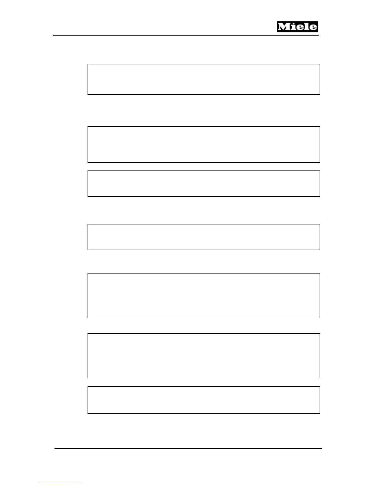
Figure 031-5: Drying Process after Flame Has Gone Out
If the flame goes out, the sluggishness of flame sensor B1/16 will cause gas
to continue flowing until gas solenoid valve Y57/2 closes and stops the gas
flow. For safety time, refer to Section 031-2.1.3. If the burner overheats, the
thermostat/temperature limiter (1F1, 2F1) interrupts the voltage circuit of gas
solenoid Y57, so gas solenoids Y57/1 and Y57/2 shut off.
2.1.3 Safety Time
The safety time is the time span between the point when the flame goes out
and the gas supply shuts off.
2.1.4 Heater Bank NTC (2R30)
Heater bank NTC 2R30 is located at the reflective plate, under the back
service panel. For NTC resistance values, refer to Table 030-3.
2.1.5 Temperature Limiters (1F1, 2F1)
Two ¾” bi-metal temperature limiters (1F1, 2F1) with manual reset at the
burner. The bi-metal temperature limiter 1F1 at the burner exit detects any
overheating of the burner due to insufficient air or air leakage. The bi-metal
temperature limiter 2F1 at the burner entrance detects any flame flashback.
32
Page 33
T 980x/T 982x
4 Service
Note:
When working on a gas dryer (T 982x), the drum door must be closed.
If the front panel is off, the opening to the drum needs to be blocked off.
4.1 Checking the Gas Burner
Danger!
Danger of burning.
Gas will ignite at igniter electrode E1/1 once the electrode has received
voltage and begun to glow.
Note:
There is a measuring port for jet pressure at the gas valve, but no
measuring port for the gas-tapping pressure.
1. Test the gas resting pressure (target value: 4 ounces per square inch
(17.4 millibars)).
Technical Information
Note:
Gas resting pressure is the pressure of gas that is stationary, without
tapping the gas.
2. Check the gas-tapping pressure (target value: 1.9 ounces per square inch
(8.2 millibars)).
Note:
Gas-tapping pressure is the gas flow pressure at the connection of the
dryer, with the burner running.
This pressure can only be measured while operating, with a functional
burner.
3. Check the temperature limiters (1F1, 2F1) for continuity.
Warning!
If the front temperature limiter (2F1) has tripped, assume that the burner
and its connecting cables have sustained thermal damage by a flashback.
In this case, replace the burner and its connecting cables.
At the same time, check the general area of the burner for heat damage.
Warning!
If the rear temperature limiter (1F1) has tripped, check the exhaust air
duct and the fan for heat damage.
33
Page 34
Technical Information
4. Check the function of the exhaust air duct and the fan.
5. Check the flame sensor (B1/16) for continuity (at room temperature).
Danger!
Danger of high voltage when working on the appliance while it's opened.
Components carry voltage.
6. Start the drying program.
7. Check if the heater relays (1K1/1) and (2K1/1) close.
8. Check if the maintaining coil and the booster coil of gas solenoid Y57/1
are receiving voltage, and if the gas solenoid opens audibly.
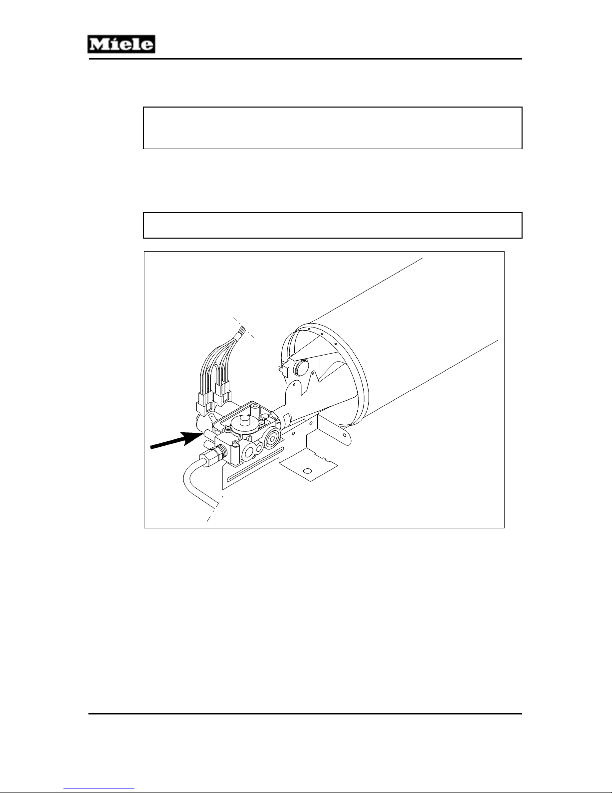
Note: No gas flow since gas solenoid Y57/2 is closed.
T 980x/T 982x
Figure 031-6: Port for Measuring Jet Pressure
9. Check that no gas flows out, and measure the gas-tapping pressure;
refer to Figure 031-6.
10. Check if igniter electrode E1/1 carries voltage and starts glowing.
11. With igniter electrode E1/1 red-hot, check if flame sensor B1/16 opens.
12. Now check if gas solenoid valve Y57/2 receives voltage via low-ohmic
igniter electrode E1/1 and opens. For jet pressure, refer to Figure 031-6.
13. Check if gas solenoid Y57/1 continues to be open via the maintaining coil
of the gas solenoid.
14. With the flame gone out, check if gas solenoid Y57/2 closes flame sensor
B1/16 within the safety time and shuts off the gas stream. For safety time,
refer to Section 031-2.1.3.
34
Page 35
T 980x/T 982x
4.2 Removing the Gas Solenoid
1. Disconnect the machine from the power and gas supplies.
2. Remove the dryer lid; refer to Section 010-4.1.
3. Remove the front panel; refer to Section 010-4.2.
4. Remove the left side panel; refer to Section 010-4.3.
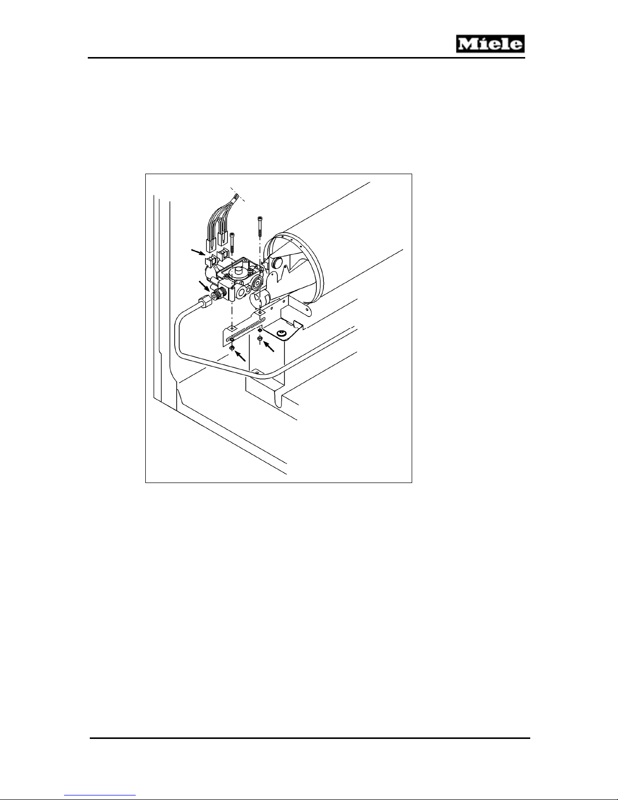
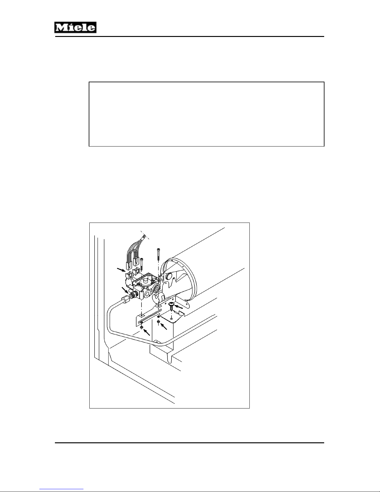
5. Pull the plugs off the gas regulation valve. See Figure 031-7.
Technical Information
Figure 031-7: Gas Regulation Valve
6. Release the connecting line from the gas regulation valve using two
metric 17mm open-end wrenches. With one wrench, loosen the nut on
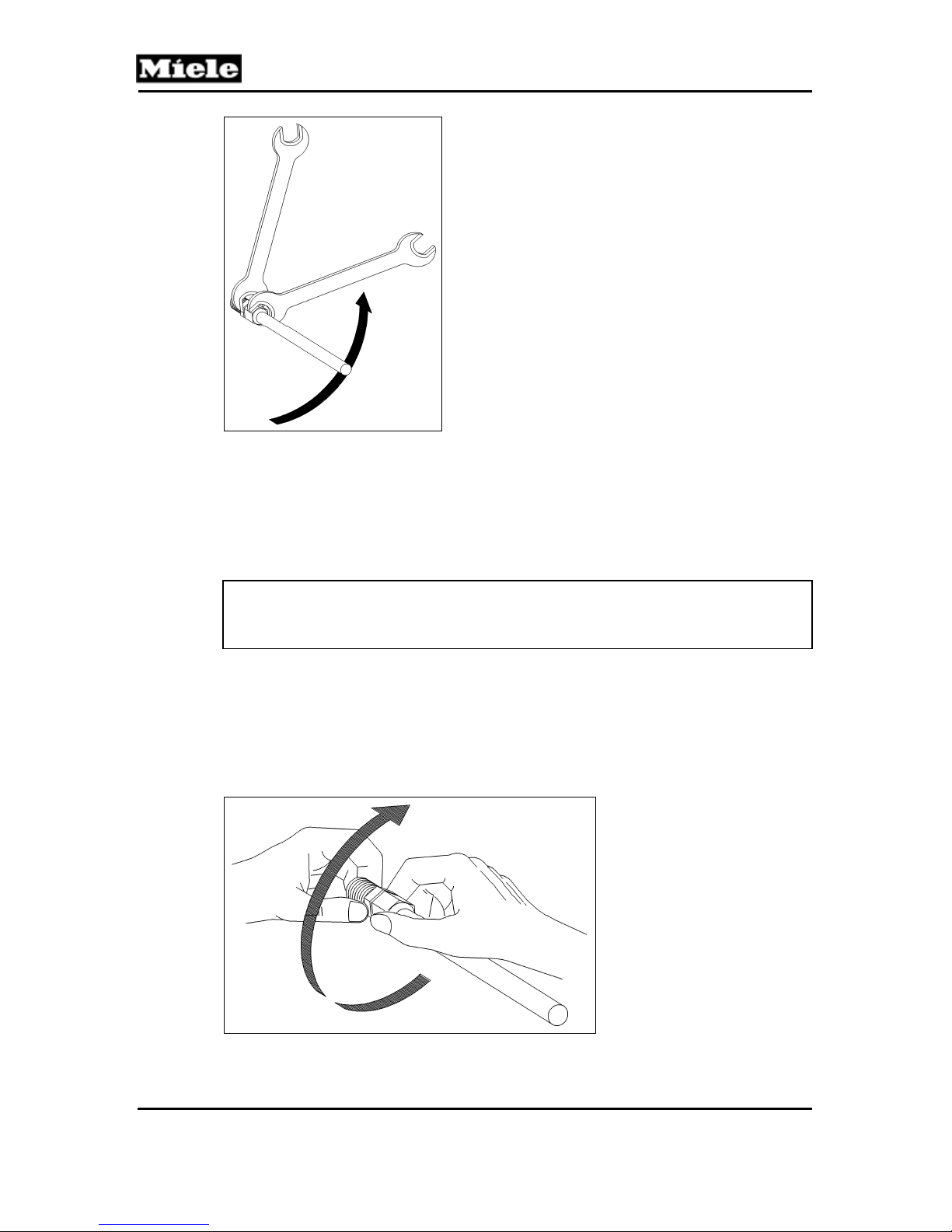
the gas line, and with the other, maintain counterpressure on the valve.
See Figure 031-8.
35
Page 36
Technical Information
T 980x/T 982x
Figure 031-8: Disconnecting the Gas Regulation Valve
7. Remove the retaining bracket of the gas regulation valve using a metric
7mm Allen wrench and a Phillips-head screwdriver.
8. Take the gas regulation valve off the burner.
4.3 Installing the Gas Solenoid Valve
Warning!
Clean soiled components with spray cleaner (MICROTEC Profi-Clean, mat.
no. 05321000).
1. Insert the gas regulation valve into the burner.
2. Fasten the bracket of the gas regulation valve, using a metric 7mm Allen
wrench and a Phillips screwdriver.
3. Using two metric 17mm wrenches, attach the gas connecting line to the
gas regulation valve. Fasten the connecting nut and turn all the way to its
stop. See Figure 031-9.
Figure 031-9: Attaching the Gas Connecting Line to the Gas Regulation Valve
36
Page 37
T 980x/T 982x
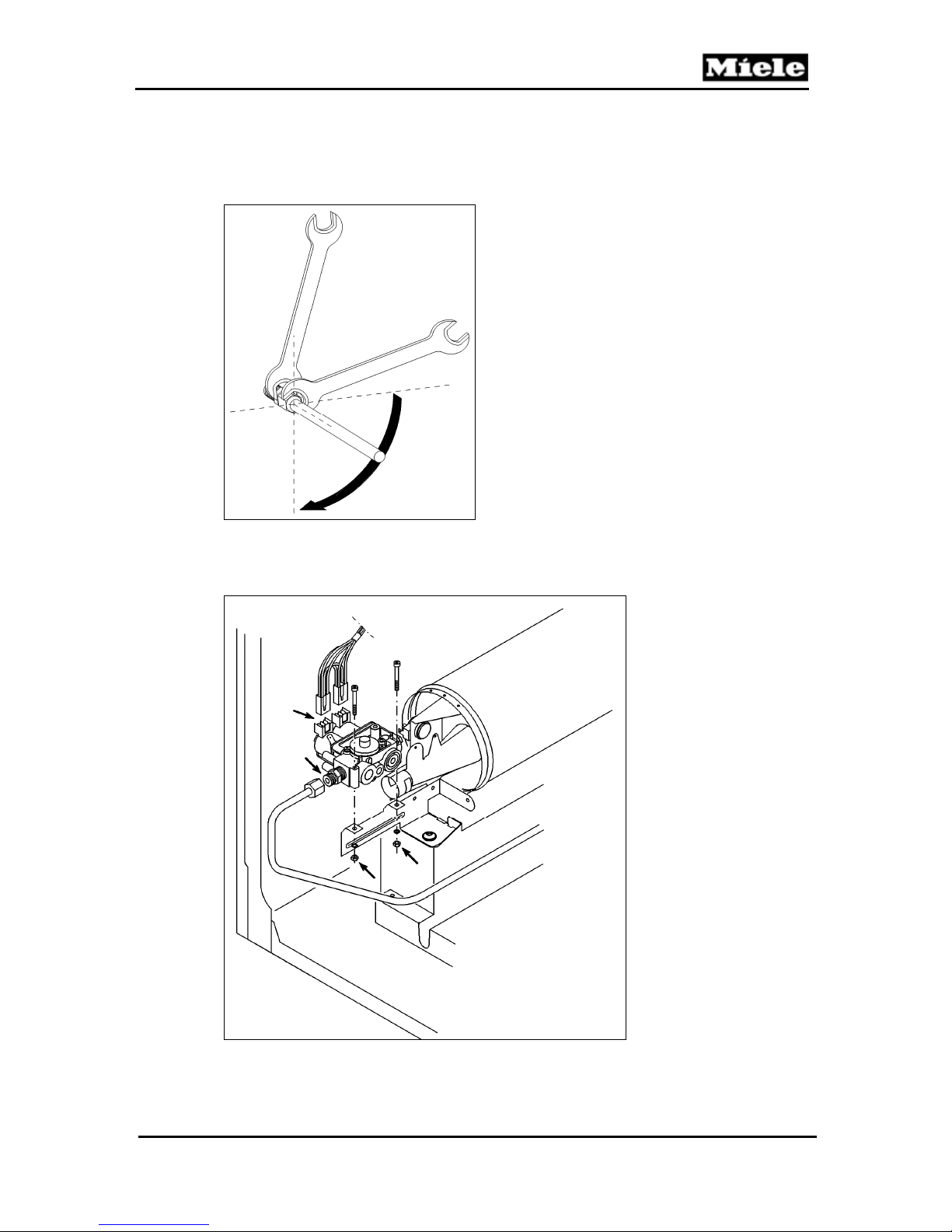
4. For the permanent assembly, give the connecting nut another quarter-
Technical Information
turn with a metric 17mm open-end wrench (19 Nm ± 1 Nm) while
maintaining counterpressure on the double nipple with a second metric
17mm open-end wrench. See Figure 031-10.
Figure 031-10: Tightening the Gas Regulation Valve
5. Connect the 2 plugs and the ground lead to the gas regulation valve. See
Figure 031-11.
Figure 031-11: Gas Regulation Valve
37
Page 38
Technical Information
6. Attach the right side panel.
7. Attach the front panel.
8. Attach the fascia panel.
9. Attach the dryer lid.
Warning!
Perform an electrical safety check.
Perform a gas safety check.
With the system under normal gas pressure, check the gas connections for
a tight seal using a spray such as Leak Test.
Check the dryer for correct function.
4.4 Removing the Gas Burner
1. Disconnect the machine from the power and gas supplies.
2. Remove the dryer lid; refer to Section 010-4.1.
3. Remove the front panel; refer to Section 010-4.2.
4. Remove the left side panel; refer to Section 010-4.3.
5. Remove the gas solenoid valve; refer to Section 031-4.2.
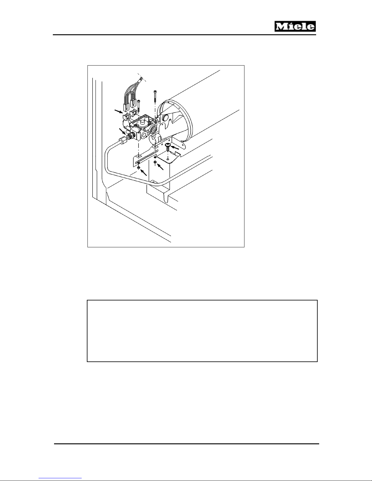
6. Loosen the burner retaining screw and take the burner off. See Figure 031-12.
T 980x/T 982x
Figure 031-12: Gas Regulation Valve
38
Page 39
T 980x/T 982x
4.5 Installing the Gas Burner
1. Secure the burner with a screw. See Figure 031-13.
Technical Information
Figure 031-13: Gas Regulation Valve
2. Install the gas solenoid valve; refer to Section 031-4.3.
3. Attach the left side panel; refer to Section 010-4.3.
4. Attach the front panel; refer to Section 010-4.2.
5. Attach the fascia panel.
6. Install the dryer lid; refer to Section 010-4.1.
Warning!
Perform an electrical safety check.
Perform a gas safety check.
With the system under normal gas pressure, check the gas connections for
a tight seal using a spray such as Leak Test.
Check the dryer for correct function.
39
Page 40
Technical Information
040 Motor, Fan
T 980x/T 982x
40
Page 41
T 980x/T 982x
1 Technical Data
Vented Dryer Gas Dryer
Motor, fan
Fan, volume flow, free
flowing
Table 040-1: Fan and Motor Data
4 Service
4.1 Fan Impeller Replacement
1. Disconnect the machine from the power supply.
2. Remove the dryer lid; refer to Section 010-4.1.
3. Remove the fascia, the electronic, and the electronic's support panel; refer
to Section 090-4.4.
4. Remove the front panel; refer to Section 010-4.2.
5. Remove the right side panel; refer to Section 010-4.3.
6. Remove the air shield; see Section 050-4.1.
7. Prop up the front of the drum to reduce any strain on the rear bearing.
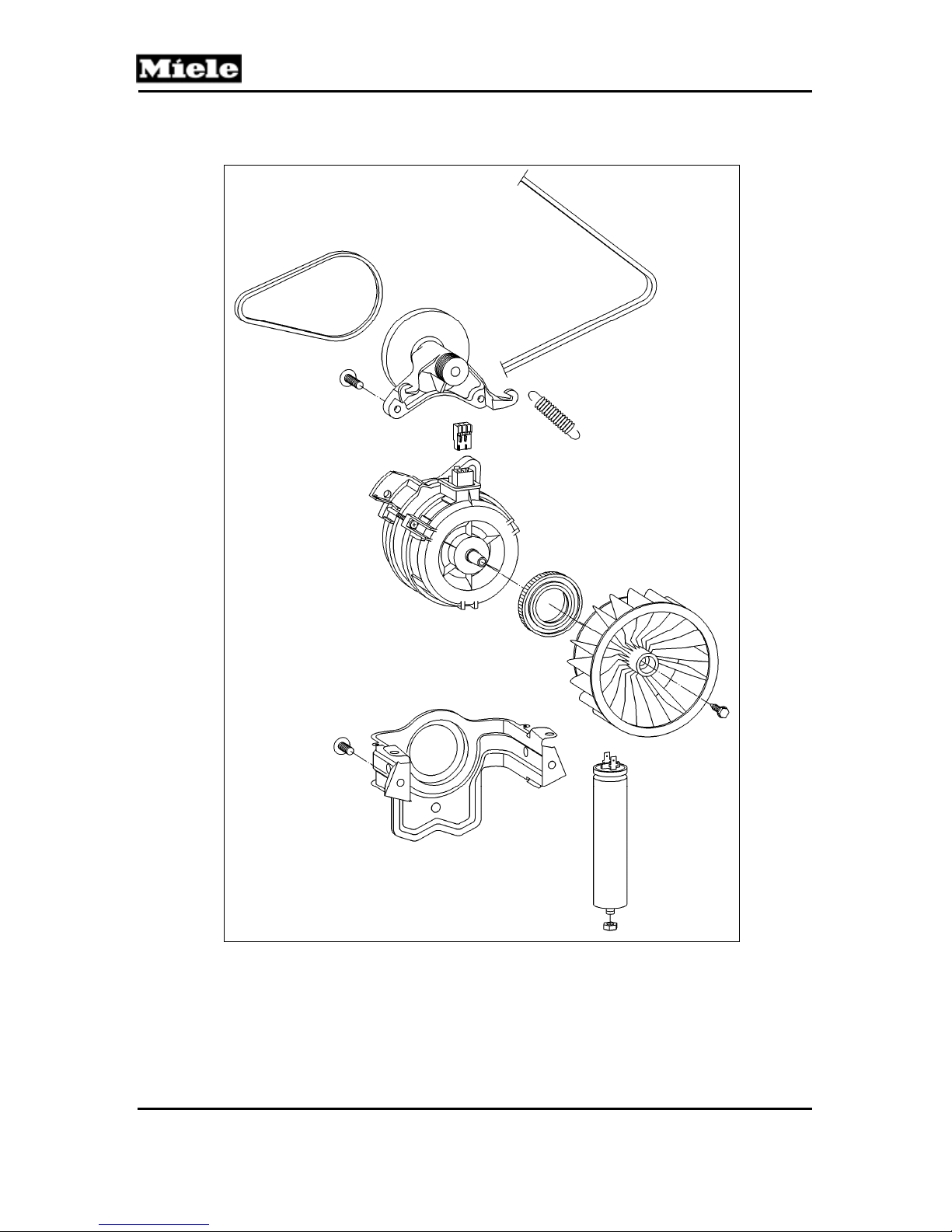
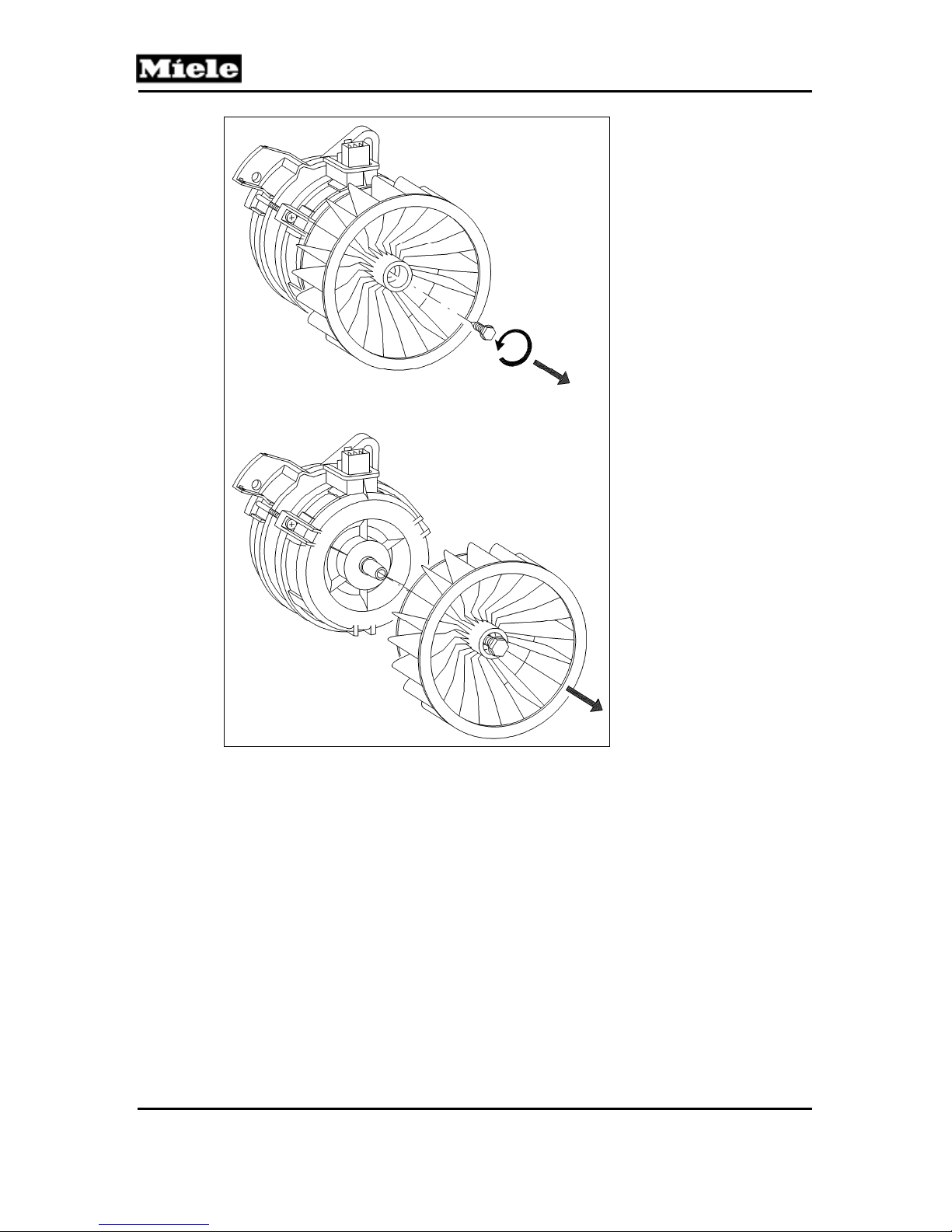
8. Hold the rear motor shaft (behind the fan) in place with a 13-millimeter
wrench. Loosen the fan impeller bolt by turning it counterclockwise using a
10-millimeter socket (use a ratcheting wrench with an extension to generate
enough torque). See Figure 040-1. Pull the impeller forward to remove.
Technical Information
Approx. motor rating 400W
Approx. 200cfm (66' pipe, d = 4”, straight-run
without additional structures)
41
Page 42
Technical Information
T 980x/T 982x
Figure 040-1: Fan Impeller Removal
9. Install the new fan impeller, and secure it with the 10-millimeter bolt.
10. Reinstall the air shield.
11. Reinstall the metal bracket in front of the air shield.
12. Reinstall the right side panel, making sure that the grounding screws are in
their proper positions.
13. Reinstall the front panel.
14. Reinstall the electronic's support panel, the electronic, and the fascia panel.
15. Reconnect the machine to the power supply and test it for correct operation.
16. Once correct operation has been verified, reinstall the lid.
42
Page 43

T 980x/T 982x
4.2 Motor Replacement
1. Disconnect the machine from the power supply.
2. Remove the dryer lid; refer to Section 010-4.1.
3. Remove the fascia, the electronic, and the electronic's support panel; refer to
Section 090-4.4.
4. Remove the front panel; refer to Section 010-4.2.
5. Remove the right side panel; refer to Section 010-4.3.
6. Unhook the spring from the intermediate drive notch (located directly below the
drum belt).
7. Release the drum belt.
8. Prop up the front of the drum to reduce any strain on the rear bearing.
9. Remove the air shield; see Section 050-4.1.
10. Remove the fan impeller. See Section 040-4.1.
11. Remove the T30 screw securing the left rear of the motor bracket, and the T30
screw securing the bottom of the motor bracket. Disconnect the Molex
connection and the ground wire (use needlenose pliers, if necessary).
12. Lift the motor up and out from the right side of the machine.
13. Install the new motor. Secure the motor bracket with the two T30 screws.
Reconnect the Molex connection and the ground wire.
14. Reinstall the fan impeller.
15. Reinstall the air shield.
16. Reinstall the heater bank.
17. Reinstall the drum, the rear bearing, and the drum belt.
18. Hook the tension spring back onto the intermediate drive notch, using
needlenose pliers if necessary.
19. Reposition the drum belt and spin the drum to ensure proper installation on the
motor drive.
20. Reinstall the metal bracket in front of the air shield.
21. Reinstall the right side panel, making sure that the grounding screws are in
their proper positions.
22. Reinstall the front panel.
23. Reinstall the electronic's support panel, the electronic, and the fascia panel.
24. Reconnect the machine to the power supply and test it for correct operation.
25. Once correct operation has been verified, reinstall the lid.
Technical Information
43
Page 44
Technical Information
050 Air Shield, Front Bearing
T 980x/T 982x
44
Page 45
T 980x/T 982x
1 Technical Data
Filter
Drying air temperature sensor
Table 050-1: Air Shield Data
Flat filter
NTC (1R30)
3 Fault Repair
3.1 Vibration Noises from the Base Plate
Cause:
The exhaust module vibrates during appliance operation, which causes
vibrations in the base plate of the appliance. A buzzing or humming noise is
generated.
Remedy:
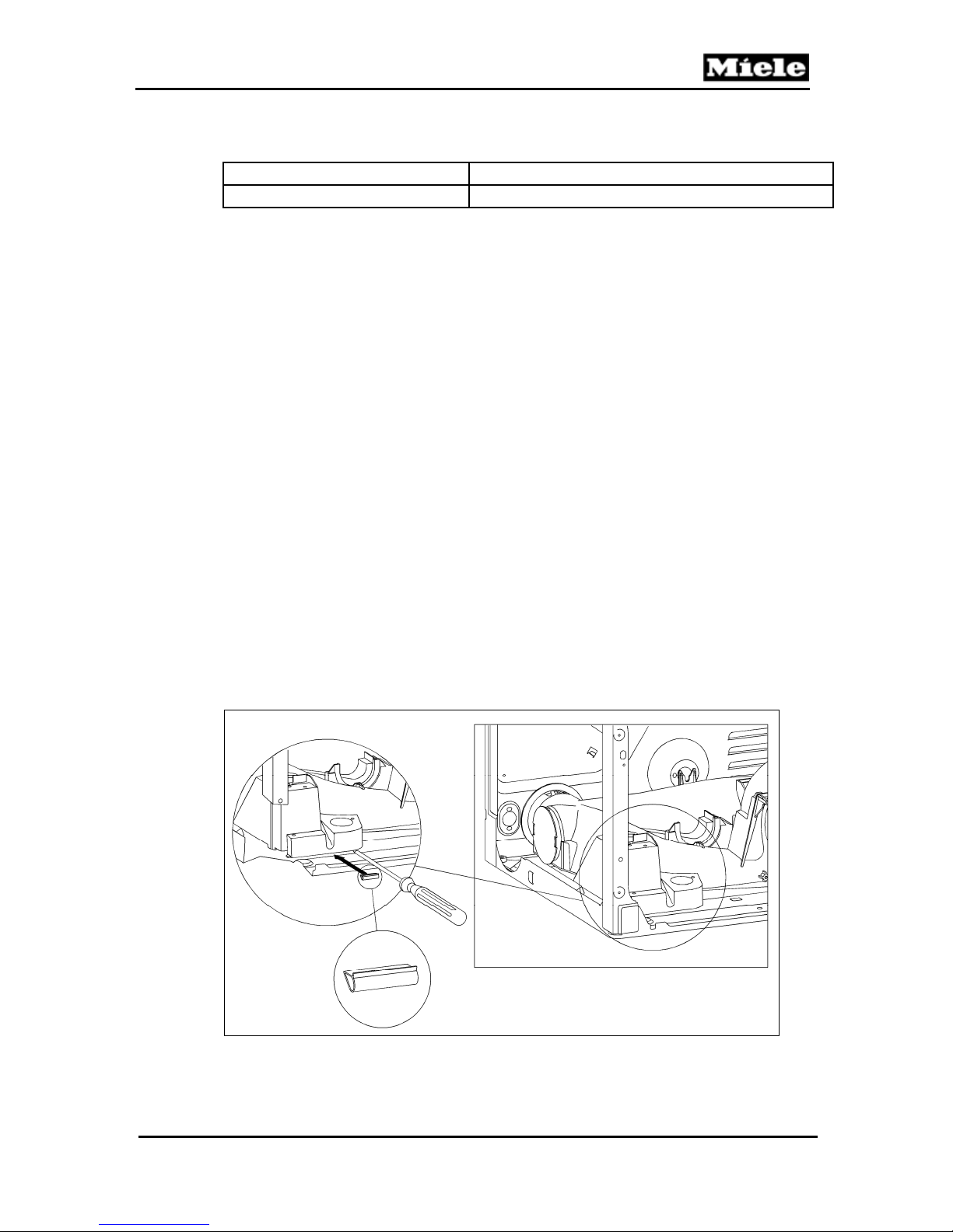
Insert a sealing strip (mat. no. 06808080) between the exhaust module
and the base plate:
1. Disconnect the machine from the power supply.
2. Remove the front panel; see Section 010-4.2
3. Place a thin flathead screwdriver between the exhaust module and the
base plate.
4. Use a thicker screwdriver to widen the gap between the exhaust module
and the base plate.
5. Remove the protective film from the sealing strip.
6. Insert the sealing strip into the gap and adhere it under the groove under
the exhaust module, making sure that the strip is centered.
7. Remove the thin screwdriver.
8. Replace the front panel.
Technical Information
Figure 050-1: Sealing Strip Installation
45
Page 46
Technical Information
4 Service
4.1 Air Shield Removal
1. Disconnect the machine from the power supply.
2. Remove the dryer lid; refer to Section 010-4.1.
3. Remove the fascia, the electronic, and the electronic's support panel;
refer to Section 090-4.4.
4. Remove the front panel; refer to Section 010-4.2.
5. Remove the right side panel; refer to Section 010-4.3.
6. Remove the two T20 screws securing the top and left side of the metal
bracket in front of the air shield.
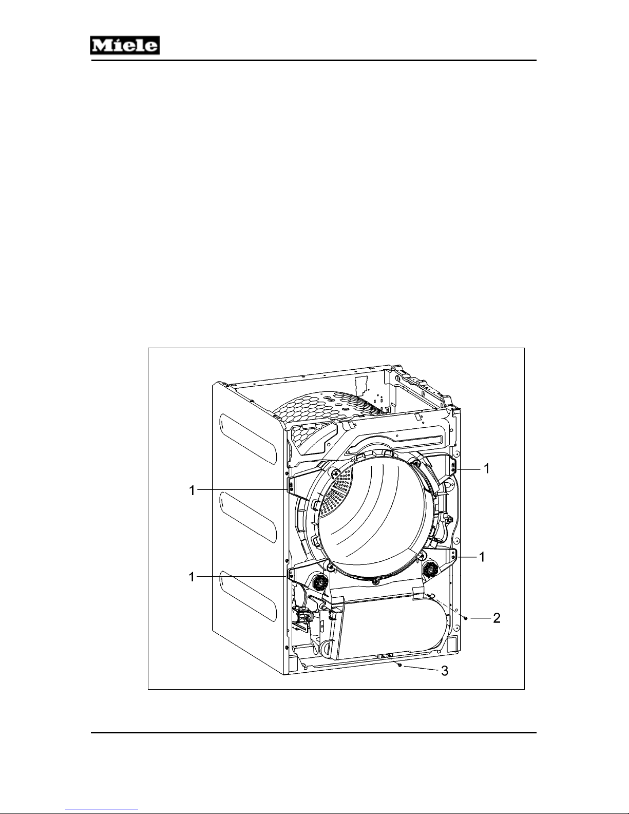
7. Remove the four T20 screws securing the sides of the air shield. See
Figure 050-2, Item 1.
8. Prop up the front of the drum to reduce any strain on the rear bearing.
9. Remove the T30 screw securing the right side of the fan cover (use a
ratchet with a 10-inch extension, if necessary). See Figure 050-2, Item 2.
10. Remove the T30 screw securing the bottom of the fan cover (use a
ratchet with a 10-inch extension). See Figure 050-2, Item 3.
11. Lift the air shield up slightly, release it from the casing, and pull it down
and out; disconnect any electrical connections.
T 980x/T 982x
Figure 050-2: Air Shield Removal
46
Page 47
T 980x/T 982x
4.2 Felt Seal Replacement
1. Disconnect the machine from the power supply.
2. Remove the air shield (Section 050-4.1) but do not disconnect any electrical
connections.
3. Lean the air shield against the appliance with the felt seal exposed.
4. Prop up the front of the drum to reduce any strain on the rear bearing.
5. Remove the felt seal by gently prying up the three staples.
6. Clean the drum where the new seal will make contact.
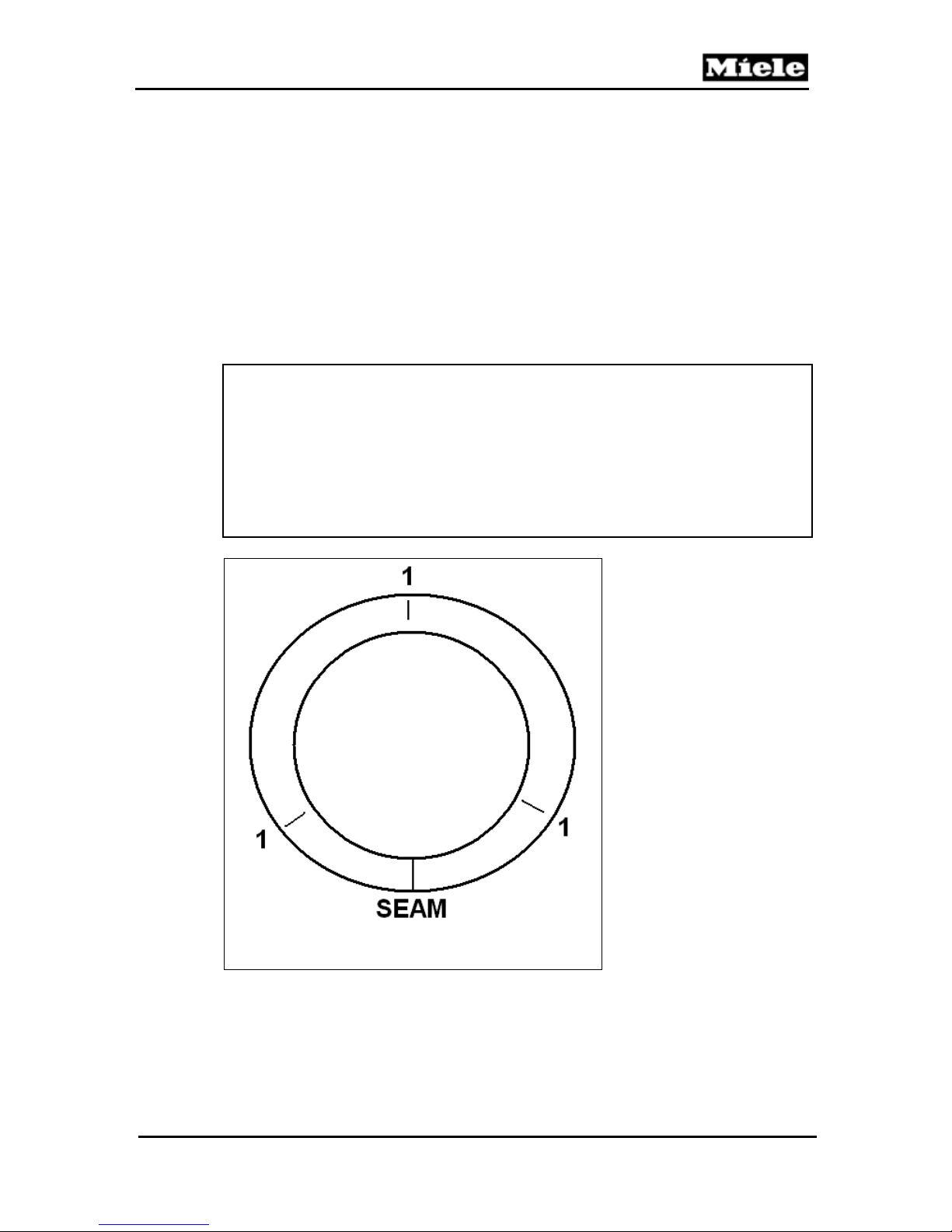
7. Install the new felt seal with the seam facing straight down (6 o'clock position).
See Figure 050-3.
8. Staple the felt seal at the 12, 4 and 8 o'clock positions. See Figure 050-3, Item 1.
Note:
When stapling the felt seal, note the following:
Ensure that the stapler is set to maximum tension for proper penetration.
Ensure that the felt is lifted back without shifting the rubber base.
Ensure that the stapler is held firmly against the felt seal rubber base and
the air shield.
Ensure that the staple penetrates the air shield.
Technical Information
Figure 050-3: Felt Seal Installation
9. Inspect the fan impeller for dirt, debris or damage. Replace if necessary
(see Section 040-4.1).
10. Reinstall the air shield, following the instructions in Section 050-4.1 in
47
Page 48

Technical Information
reverse order.
11. Reinstall the metal bracket in front of the air shield.
12. Hook the tension spring back onto the intermediate drive notch, using
needlenose pliers if necessary.
13. Reinstall the right side panel, making sure that the grounding screws are in
their proper positions.
14. Reinstall the front panel.
15. Reinstall the electronic's support panel, the electronic, and the fascia panel.
16. Reconnect the machine to the power supply and test it for correct
operation.
17. Once correct operation has been verified, reinstall the lid.
T 980x/T 982x
48
Page 49
T 980x/T 982x
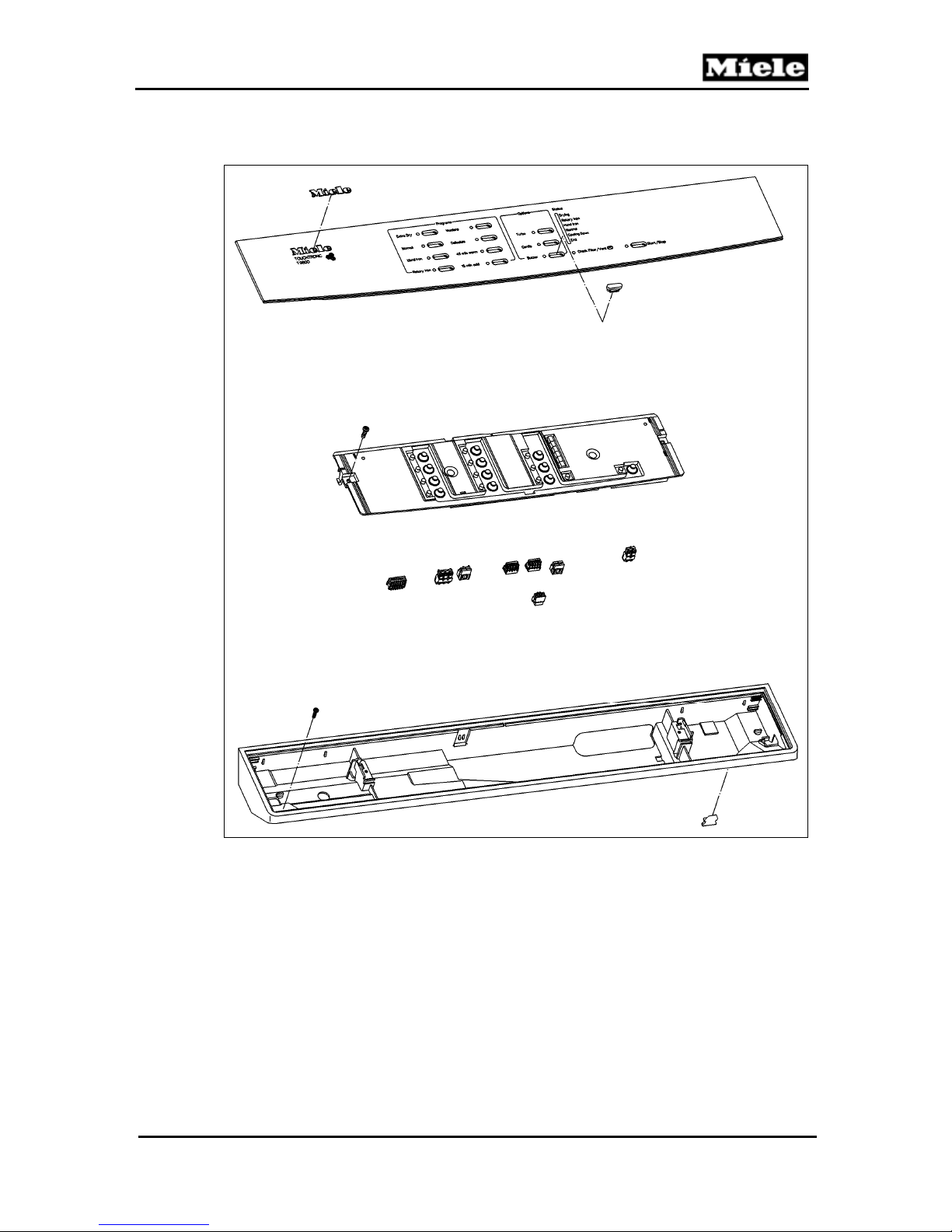
090 Fascia Panel, Electronic
Technical Information
49
Page 50
Technical Information
1 Technical Data
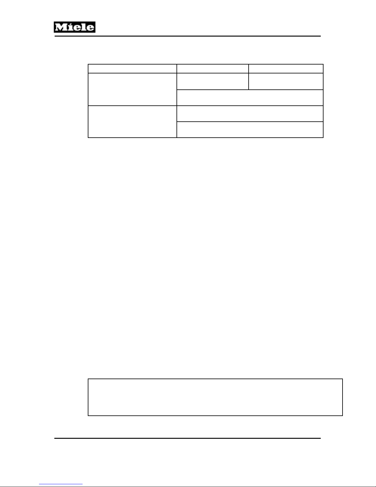
Electric Heating Gas Heating
USA: EPWL 341
Electronic (1N1)
Drying technology
Table 090-1: Technical Data
(single-board electronic)
Can be updated via optical PC interface installed
standard
Residual moisture sensing: conductivity test,
residual moisture sensor (B3/1), 1-rib sampling
Insufficient air detection via heater bank NTC 2R30
and drying air NTC 1R30
2 Function
2.1 Reversing (Electric) (T 980x)
Reversing rhythm: 5 minutes clockwise (default direction), 1.5-second
pause, 30 seconds running counterclockwise, 1.5-second pause.
During the clockwise run, shortly before the pause, heating is reduced to a
basic output of 1.9kW.
2.2 Reversing (Gas) (T 982x)
During the drying cycle, the gas dryer will not reverse for residual laundry
moisture levels below 20%.
For residual moisture levels greater than 20%, a maximum of 7 reversing
cycles will take place.
T 980x/T 982x
USA: EPWL 345
(single-board electronic)
Reversing rhythm: 10 minutes running clockwise (default direction), 1.5second pause and 30 seconds running counterclockwise.
The burner is switched on at the start of the clockwise run, and it is switched
off 4 seconds before the start of the counterclockwise run. During the
counterclockwise run, the burner is always off.
2.3 Dryer Function after a Power Interruption
The dryer continues automatically at the point the program was interrupted.
2.4 Programming Functions
2.4.1 Resetting to Factory Settings
Resets all programming options to their factory settings.
Note:
The reset takes effect immediately; it's not possible to restore the previous settings!
Operating hours are not reset.
Not possible with service-department electronics.
50
Page 51
T 980x/T 982x
2.4.2 Normal Drying Outcome (Residual Moisture)
Drying can be set to more damp or more dry to suit the customer's preference.
2.4.3 Delicates Drying Outcome (Residual Moisture)
Drying can be set to more damp or more dry to suit the customer's preference.
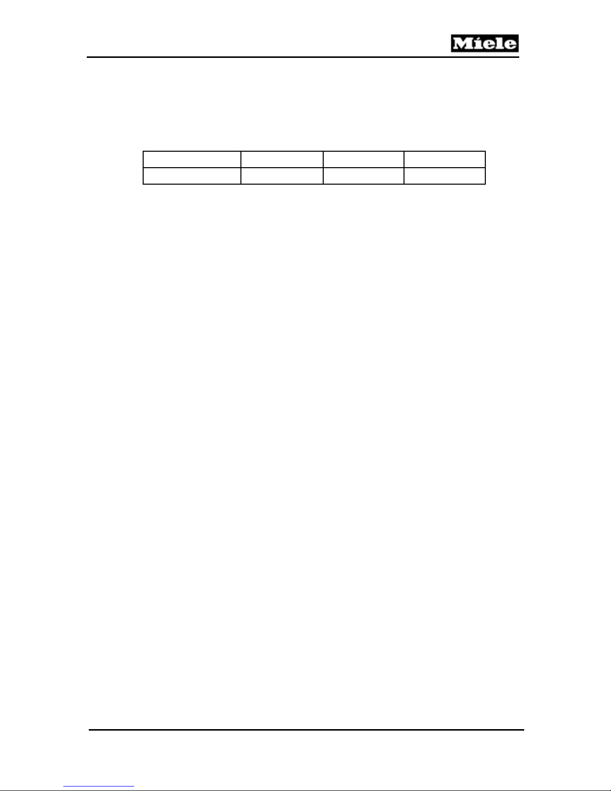
More Damp Standard More Dry
Delicates 4% 2% 0%
Table 090-2: Residual Moisture, Delicates
2.4.4 Memory
With the memory function activated, the extra features selected at the start of
a program are saved. When the same program is selected again, these extra
features are automatically called up.
2.4.5 Additional Cooldown Phase
Applies only to residual moisture programs.
An extended cooldown time reduces the temperature of the laundry at
program end. The result is that the laundry feels less damp.
The cooldown time extension has no effect on timed drying programs.
2.4.6 Prompt to Clean Air Ducts
Operators can adjust the prompt to clean air ducts to suit their needs.
For insufficient air detection, refer to Section 090-2.7.
2.4.7 Acoustical Acknowledgment
Set the acoustical tone to sound when a button is pressed.
2.4.8 Conductivity Setting
The conductivity of the damp laundry is evaluated and forms the basis of
residual moisture sensing.
For residual moisture sensing, refer to Section 090-2.5.
Soft water does not conduct as well as hard water. In areas where soft water
is used, the effect of soft water on residual moisture sensing can be
compensated for with this programming function.
2.4.9 Standby
With standby activated, the panel LEDs and the drum light are dimmed after
5 minutes to save energy.
2.5 Residual Moisture Sensing
The electronic detects the conductivity in microsiemens (µS) of the laundry
via residual moisture sensor B3/1. The residual moisture of the laundry is
based on this measured conductivity value.
Technical Information
51
Page 52
Technical Information
2.6 Overriding the Time Control
A fixed maximum time of approximately 180 minutes is imposed on all
residual moisture drying programs at program start. After this time has
elapsed, any drying program is stopped and the cooldown phase for faults is
carried out. There is no anti-crease action, and no fault code is indicated, but
the fault is saved and can be called up in service mode.
2.7 Insufficient Air Detection
The heater bank NTC (2R30) monitors the temperature increase in the heater
bank. If the air paths are clogged during heating, the temperature in the
heater bank rises rapidly. This is detected and the fault message Insufficient
air is displayed. If the temperature at the heater bank NTC exceeds 356°F
(180°C), fault code F66 (Leaking air) is issued.
2.8 Operating Hours Counter
The time is counted from program start to the end of cooldown, without the
time for delay start and anti-crease action.
2.9 Low-Voltage Detection
The motor can only run with sufficient supply voltage. Because the motor is
mechanically linked to the fan, no air current is created when the motor is not
running. The dryer will then overheat during heating and trip the circuit
breaker.
T 980x/T 982x
In order to avoid overheating, shut the dryer electronics off completely when
they detect low voltage. This is the case when the supply voltage:
- falls below the emergency threshold
- falls below the lower low-voltage value for longer than one second
- falls below the lower low-voltage value more than once in 10 seconds
When the upper low-voltage value (see Table 090-3) has been reached, the
dryer electronics may be switched back on.
USA (120V, 60Hz)
Table 090-3: Values for Low-Voltage Detection
Emergency
Threshold
Forced appliance
shutoff
Tolerance: ± 1.5%
of the nominal
voltage
< 80V
Lower Low
Voltage
Secure appliance
shutoff
Tolerance: ± 1.5%
of the nominal
voltage
< 102V - 3% of the
nominal voltage
Upper Low
Voltage
Secure appliance
switch-on
Tolerance: ± 1.5%
of the nominal
voltage
> 108V - 3% of the
nominal voltage
52
Page 53

T 980x/T 982x
3 Fault Repair
3.1 “End” LED Is Steadily Lit
Symptom:
This fault occurs in the normal operating mode (residual moisture programs only).
Program stop, cooling air phase, intermittent buzzer tone.
Opening and then closing the door deletes this fault message.
Cause:
The drum is empty, or loaded with only a few laundry items.
The laundry is too dry.
The residual moisture sensor (B3/1) voltage circuit is high-ohmic, and the residual
moisture sensor has no-load detection; this is not a technical fault.
For no-load detection, refer to Section 030-2.1.
Remedy:
Adjust the load, or switch to a timed program.
Cause:
Defective residual moisture sensor (B3/1).
Remedy:
Check the residual moisture sensor (B3/1) for low-ohmic (continuity) status; refer to
Section 090-4.3.
3.2 “Check Filter/Vent” LED Is Steadily Lit
Technical Information
Symptom:
Normal program run.
Fault indication at the end of the cooling cycle.
Insufficient air detection; refer to Section 090-2.7.
Opening and closing the door deletes this fault code indication.
Cause:
Air paths are clogged.
Remedy:
Clean the lint filter (refer to the operating instructions).
Clean the air paths in the dryer.
Cause:
The fault message Clean air paths is issued prematurely.
Remedy:
Reprogram the Clean air paths fault message indication; see the operating
instructions or Section 090-4.1.
53
Page 54

Technical Information
3.3 “Check Filter/Vent” LED Flashes Rapidly
Symptom:
Program stop, cooling phase, buzzer sounds intermittently for 2 minutes.
Fault code F66 (Leaking air fault) in the fault memory.
Cause:
Air paths are clogged.
Insufficient air measurement; refer to Section 090-2.7.
Remedy:
Clean air paths.
Delete the fault memory; refer to Section 090-4.3.
3.4 “Rotary Iron” LED Flashes
Symptom:
Program stop, cooling phase, buzzer sounds intermittently for 2 minutes.
Fault code F1 (Heater bank NTC short circuit) or F2 (Heater bank NTC open
circuit) in the fault memory.
Cause:
Heater bank NTC short- or open-circuited.
Remedy:
Check the wires and connectors of heater bank NTC 2R30 for a short or open circuit.
For heater bank NTC resistance values, refer to Table 030-3.
Delete the fault memory; see Section 090-4.3.
3.5 “Hand Iron” LED Flashes
T 980x/T 982x
Symptom:
Program stop, cooling phase, buzzer sounds intermittently for 2 minutes.
Fault code F3 (Drying air NTC (1R30) short circuit) or F4 (Drying air NTC
(1R30) open circuit) in the fault memory.
Cause:
Drying air NTC (1R30) open circuit (below 68°F); evaluation only after the
heater has been running for at least 1 minute.
Remedy:
Check the wires and connectors of drying air NTC 1R30 for a short or open
circuit.
For drying air NTC resistance values, refer to Table 030-3.
Cause:
Heater bank is not heating. Unheated, the sensor is below the measuring
threshold of 68°F (electric dryers only).
Remedy:
Check the heater element (R1) for a short or open circuit.
Cause:
Defective heater relay (K1/1) (electric dryers only).
Remedy:
Check the heater relay (K1/1).
54
Page 55

T 980x/T 982x
Cause:
Temperature limiter with manual reset (F1) has tripped (electric dryers only).
Remedy:
1. Reset the temperature limiter.
2. Find and rectify the cause for the temperature limiter tripping.
Cause:
Gas burner is not heating (gas dryers only).
Remedy:
Check the burner; refer to Section 031-4.1.
3.6 All Program LEDs Flash
Symptom:
No program start and no access to the programming or service mode.
Cause:
Demo mode is activated.
Remedy:
Deactivate the demo mode; refer to Section 090-4.2.
3.7 F0: No Fault
Technical Information
Cause:
No fault is saved in the fault memory.
Remedy:
None.
3.8 F1: Short Circuit in Heater Bank NTC (2R30)
Symptom:
Program stop, cooling phase, intermittent buzzer tone.
Only the timed program “cold air” still works.
The “Rotary iron” LED flashes.
The “Check Filter/Vent” LED flashes.
Opening and closing the door deletes this fault indication.
Cause:
Short circuit in heater bank NTC (above 480°F).
Remedy:
Check the wires and connectors of the heater bank NTC for a short or open circuit.
For heater bank NTC resistance values, refer to Table 030-3.
3.9 F2: Open Circuit in Heater Bank NTC (2R30)
Symptom:
Program stop, cooling phase, intermittent buzzer tone.
Only the timed program “cold air” still works.
The “Rotary iron” LED flashes.
The “Check Filter/Vent” LED flashes.
Opening and closing the door deletes this fault indication.
55
Page 56

Technical Information
Cause:
Open circuit at heater bank NTC (below 68°F); evaluation only after the
heater has been running for at least 1 minute.
Remedy:
Check the wires and connectors of heater bank NTC 2R30 for a short or open
circuit.
For heater bank NTC resistance values, refer to Table 030-3.
Cause:
Heater bank is not heating. Without heat, the sensor is below the measuring
threshold of 68°F (electric dryers only).
Remedy:
Check the heater bank (R1) for a short or open circuit.
Cause:
Heater relay (K1/1) (electric dryers only).
Remedy:
Check the heater relay (K1/1).
Cause:
Temperature limiter with manual reset (F1) has tripped (electric dryers only).
Remedy:
Reset the temperature limiter.
Find and rectify the cause for the temperature limiter tripping.
T 980x/T 982x
Cause:
Gas burner not heating (gas dryers only).
Remedy:
Check the gas burner; refer to Section 031-4.1.
3.10 F3: Drying Air NTC (1R30) Short Circuit
Symptom:
Program stop, cooling phase, intermittent buzzer tone.
Only the timed program “cold air” still works.
The “Hand iron” LED flashes.
The “Check Filter/Vent” LED flashes.
Opening and closing the door deletes this fault indication.
Cause:
Short circuit (above 320°F) in drying air NTC 1R30.
Remedy:
Check the wires and connectors of drying air NTC 1R30 for a short or open circuit.
For drying air NTC resistance values, refer to Table 030-3.
56
Page 57

T 980x/T 982x
3.11 F4: Drying Air NTC (1R30) Open Circuit
Symptom:
Program stop, cooling phase, intermittent buzzer tone.
Only the timed program “cold air” still works.
The “Hand iron” LED flashes.
The “Check Filter/Vent” LED flashes.
Opening and closing the door deletes this fault indication.
Cause:
Open circuit (below 5°F) in the drying air NTC (1R30).
Remedy:
Check the wires and connectors of drying air NTC 1R30 for a short or open circuit.
For drying air NTC resistance values, refer to Table 030-3.
3.12 F50: Motor Stalls and Heater Is On for 3 Seconds
Symptom:
The motor (M5) stalls.
Program stop, cooling phase, intermittent buzzer tone.
Opening and closing the door deletes this fault indication.
Technical Information
Cause:
This is an internal electronic fault.
Remedy:
1. Check the motor.
2. Replace the electronic.
3.13 F55: Overriding Time Limit Exceeded
Symptom:
Only in residual moisture programs.
Program stop, cooling phase, intermittent buzzer tone for 2 minutes.
The “End” LED lights up steadily.
The “Check Filter/Vent” LED lights up steadily.
Opening and closing the door deletes this fault indication.
The safety time has been exceeded; refer to Section 090-2.6.
Cause:
Laundry too wet, or dryer overloaded.
Remedy:
Spin the laundry more thoroughly in the washer, or reduce the laundry load.
Cause:
Laundry is electrically conductive (low-ohmic), due to a metal zipper, for example.
Remedy:
Run a timed warm-air program.
Cause:
Air path clogged.
Remedy:
Check and clean the air paths.
57
Page 58
Technical Information
Cause:
Heater bank is not heating.
Remedy:
Check the heater element (R1) for a short or open circuit.
Cause:
Heater relay (K1/1).
Remedy:
Check the heater relay (K1/1).
Cause:
Temperature limiter (SOD, F2).
Remedy:
Check the temperature limiter (SOD, F2) for an open circuit.
Cause:
Defective residual moisture sensor (B3/1).
Remedy:
Residual moisture sensor (B3/1): Check the sampler.
Check the residual moisture sensor (B3/1) voltage circuit for high ohmic (isolation)
status; see Section 090-4.3.
3.14 F66: Air Leakage
T 980x/T 982x
Symptom:
Program stop, cooling phase, intermittent buzzer tone for 2 minutes.
Cause:
Air paths clogged.
Insufficient air measurement; refer to Section 090-2.7.
Remedy:
Clean the air paths.
3.15 F98: No Gas Ignition (T 982x only)
Symptom:
Program stop, cooling phase, intermittent buzzer tone.
Cause:
The burner has not ignited after 10 attempts.
Remedy:
Check the following:
- Gas supply is open
- Gasline pressure is available
- Exhaust passageway is clear
- Gas jet is clear
- Ignition electrode is functioning
Note:
In order to clear this fault message, open and close the door with the
appliance switched on.
58
Page 59
T 980x/T 982x
Technical Information
3.16 Laundry Is Overdried/F55 (Overriding Time Limit Exceeded)
Symptom:
Very long operating time.
F 55 is stored in the fault memory.
Cause:
Short circuit at drum contact strip.
A metal bracket of the drum contact strip is touching the drum casing and has
caused a short circuit. Therefore, the electronics are detecting moisture, even
though the laundry is already dry.
Remedy:
Insulate the bracket from the drum casing by placing an insulating sleeve
(mat. no. 07244210) around the bracket.
Note:
In order to clear this fault message, open and close the door with the
appliance switched on.
3.17 Dryer Shuts Itself Off
Symptom:
Dryer shuts itself off suddenly during operation.
No fault message; no additional symptoms.
Cause:
Not enough supply voltage available.
See Section 090-2.9.
Remedy:
No remedy needed, because the electronics will switch the dryer on again
when they have detected sufficient voltage.
Cause:
The electronic prematurely detects a low voltage.
The values for low-voltage detection have been adjusted. For current lowvoltage detection values, see Table 090-3.
Remedy:
Measure the input voltage to determine if the dryer has shut off in accordance
with the values shown in the table. If possible, measure the voltage while a
drying program is running and heating is switched on.
If the dryer has shut off prematurely, replace the electronic.
59
Page 60
Technical Information
4 Service
4.1 Programming Mode Summary
Initial requirements:
1. End the current program as well as the demo mode.
2. Open the door.
Accessing:
Note: Access has to be completed within 10 seconds.
1. Press and hold the Start/Stop button.
2. Close the door.
3. As soon as the “Start/Stop” LED flashes, release the Start/Stop button.
4. Immediately press Start/Stop 5 times and on the 5th time hold it until the
“Start/Stop” LED flashes rapidly (5 flashes per second).
Acknowledgement indicator:
“Start/Stop” LED flashes rapidly (5 flashes per second).
If access is not successful, the machine will automatically revert to standard
operating mode.
T 980x/T 982x
Options:
1. Press the Buzzer button to select a programming function.
2. The “Buzzer” LED flashes to indicate the selected function. See Table 090-4.
3. Press the Start/Stop button to select options.
4. The “Drying” LED flashes to indicate the selected option. See Table 090-4.
Warning!
For the dryer to function properly, specific options for the country it is
operating in have to be selected.
The appropriate electronic must be installed.
Factory settings are indicated in bold.
60
Page 61
T 980x/T 982x
Technical Information
Programming Function Option
“Buzzer” LED long short “Drying” LED short
Reset, refer to Section
090-2.4.1
-- 1
adapted options 0
delivery
condition
1
Normal drying
outcome (residual
moisture), refer to
Section 090-2.4.2
Delicates drying
outcome (residual
moisture), refer to
Section 090-2.4.3
Memory, refer to
Section 090-2.4.4
Additional cooldown
phase, refer to
Section 090-2.4.5
Insufficient air alert,
refer to Section 090-
2.4.6
Button tones, refer to
Section 090-2.4.7
Conductivity setting,
refer to Section 090-
2.4.8
more damp 0
-- 2
-- 3
-- 6
-- 7
1 --
1 1
1 2
standard
more dry 2
more damp 0
standard
more dry 2
off, memory
function not
activated
on, memory
function
activated
off
5 min 1
10 min 2
off 0
more sensitive 1
standard
less sensitive 3
off 0
on
normal
low (<150µS) 1
1
1
0
1
0
2
1
0
Standby, refer to
Section 090.2.4.9
Table 090-4: Programming Mode Summary
Save and quit:
Open the door.
Note: Programming selections are saved in the electronic.
1 3
off 0
on 1
61
Page 62
Technical Information
4.2 Activating/Deactivating the Demonstration Mode
Initial requirements:
1. End the current program.
2. Open the door.
Accessing:
Note: Access has to be completed within 10 seconds.
1. Press and hold the Start/Stop button.
2. Close the door.
3. As soon as the “Start/Stop” LED lights up steadily (after about 4
seconds), release the Start/Stop button.
4. Immediately press Start/Stop again and hold until the “Start/Stop” LED
goes out (about 3 seconds).
Acknowledgement indicator:
The demo program starts running. LEDs light up one at a time and the
“Start/Stop” LED blinks.
If access is not successful, the machine will automatically revert to standard
operating mode.
T 980x/T 982x
Options:
A demo program cycle lasts about 40 seconds, then there is a short pause,
and the demo program starts again.
Operating simulation/Interactive demo mode: In interactive demo mode,
the appliance can be operated without starting a program.
Save and quit:
To deactivate the demo mode, repeat the access procedure.
4.3 Service Mode Summary
Initial requirements:
1. End the current program as well as the demo mode.
2. Open the door.
Accessing:
Note: Access has to be completed within 10 seconds.
1. Press and hold the Start/Stop button.
2. Close the door.
3. As soon as the “Start/Stop” LED flashes, release the Start/Stop button.
4. Immediately press Start/Stop 3 times and on the 3rd time hold it until the
“Start/Stop” LED flashes slowly (1 flash per second).
Acknowledgement indicator:
“Start/Stop” LED flashes slowly (1 flash per second).
If access is not successful, the machine will automatically revert to standard
operating mode.
62
Page 63
T 980x/T 982x
Options:
1. Press the Buzzer button to select a service function.
2. The “Buzzer” LED flashes to indicate the selected function. See Table 090-5.
3. Press the Start/Stop button to select options.
4. The “Drying” LED flashes to indicate the selected option. See Table 090-5.
Technical Information
Note:
The component test switches off automatically 30 minutes after the last
component is activated.
Service Functions Options
“Buzzer” LED short “Drying” LED long short
Software status
Fault memory; use
Start/Stop to scroll; to
delete the fault memory,
press and hold
Start/Stop until “Drying”
LED goes out
Component test
-- Program index XY X Y
F 0, No fault; all OK. -- --
F 1, Heater bank NTC short
circuit; refer to Section 090-3.8
F 2, Heater bank NTC open
circuit; refer to Section 090-3.9
F 3, Drying air NTC short
circuit; refer to Section 090-
3.10
F 4, Drying air NTC open
1
2
circuit; refer to Section 090-
3.11
F 50, Motor stalls and heater is
on for 3 s; refer to Section
090-3.12
F 55, Safety time exceeded;
refer to Section 090-3.13
F 66, Air leakage fault; refer to
Section 090-3.14
F 98, No gas ignition; refer to
Section 090-3.15
All components inactive --
Motor on in a rhythm of 10 s left / 2 s
pause / 10 s right / 2 s pause
Heater relay 1K1/1, heater R1 on and
motor on in a rhythm of 10 s left / 2 s
pause / 10 s right / 2 s pause.
Check the residual moisture sensor
(B3/1) for low ohmic status (continuity).
Requires an electrical connection
between drum and sensor rib.
-- 1
-- 2
-- 3
-- 4
5 --
5 5
6 6
9 8
1
2
4
63
Page 64
Technical Information
Service Functions Options
“Buzzer” LED short “Drying” LED long short
Component test
Sensor test
Operating hours,
Section 090-2.8
Table 090-5: Service Mode Summary
T 980x/T 982x
Check the residual moisture sensor
(B3/1) for high ohmic status (isolation).
Requires no electrical connection
between drum and sensor rib.
2
3
4
Steady buzzer tone 6
LEDs flash (1x per second) 7
Heater relay 2K1/1 and motor on 8
Heater relays (1K1/1, 2K1/1, 3K1/1),
heaters (R1, R2, R3) and motor on
All sensors inactive --
Door lock (A2): Door closed = switch
closed = buzzer on. Door open = switch
open = buzzer off.
Electronic's operating hours:
Long flashing signal for the
number of 1000s, short
flashing signal for the number
of 100s (e.g., 12 times long + 6
times short = 12000 h + 600 h
= 12600 h).
x000 h y00 h
5
9
1
Save and quit:
Open the door.
Note: Delete the fault memory before ending.
4.4 Removing the Fascia, Electronic and Electronic Support Panel
1. Disconnect the appliance from the power supply.
2. Remove the lid; see Section 010-4.1.
3. Pry off the fascia panel using a small flathead screwdriver.
4. Remove the two T20 screws securing the electronic (see Figure 090-1),
press in on the retaining tabs, and remove the electronic partway.
Disconnect all connections to the electronic and remove it completely.
5. Remove the four T20 screws securing the electronic support panel (see
Figure 090-1).
6. Lift the support panel out to remove.
64
Page 65
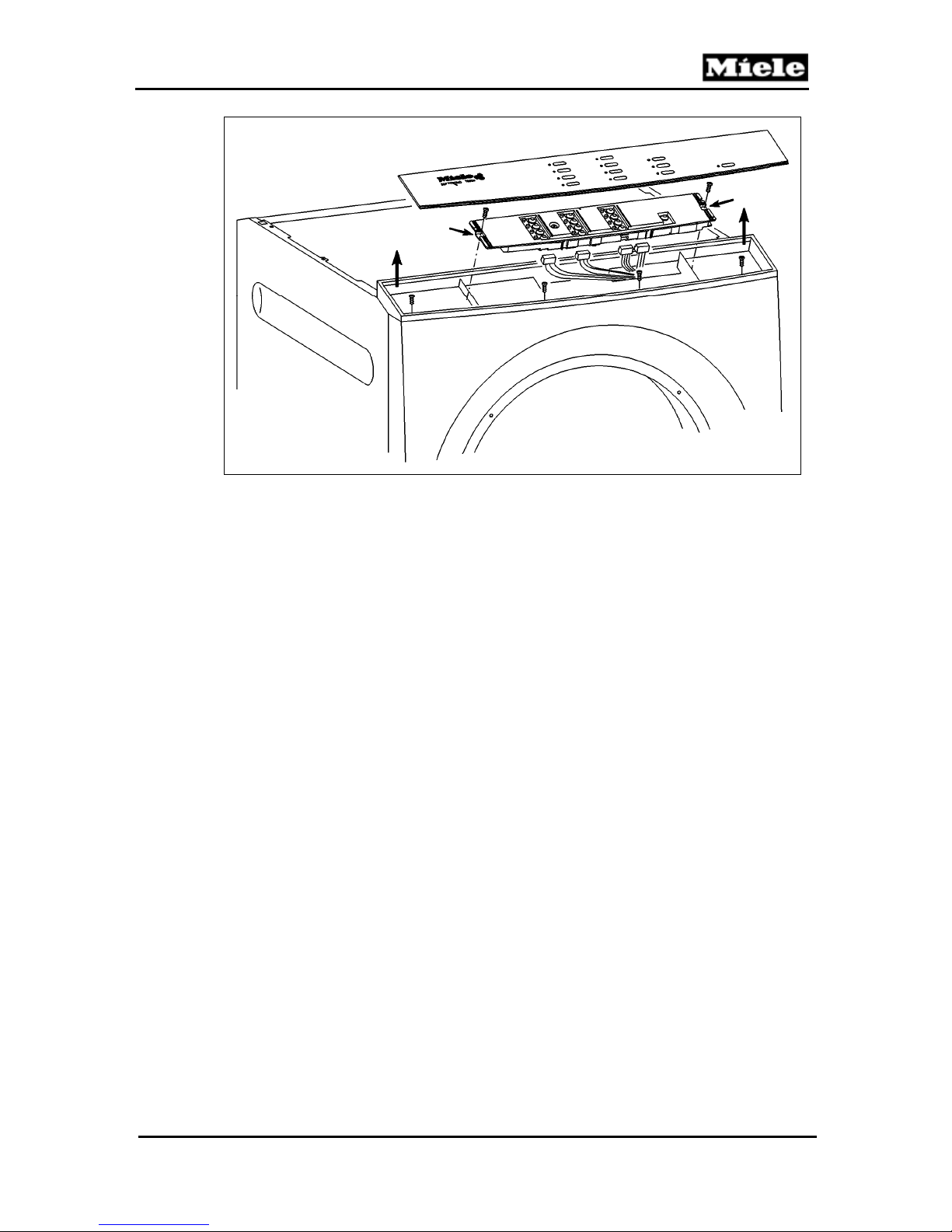
T 980x/T 982x
Technical Information
Figure 090-1: Removing the Fascia, Electronic, and Electronic Support Panel
65
Page 66
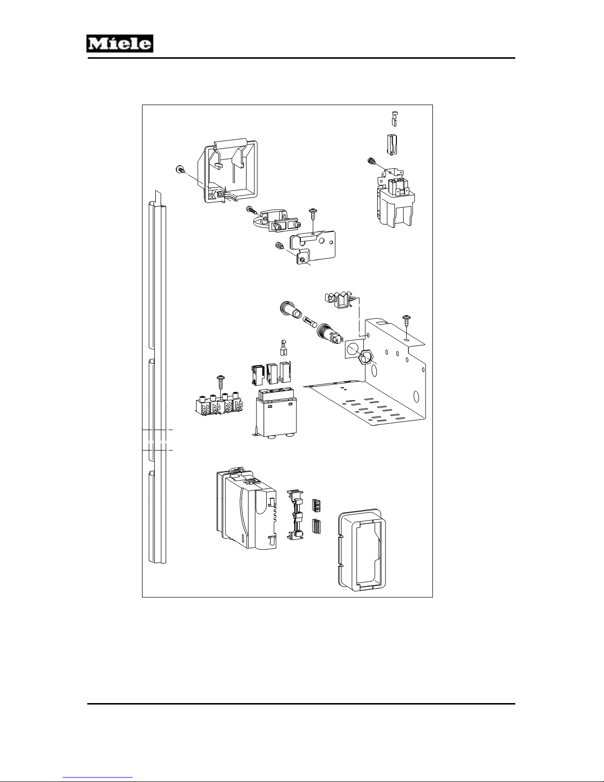
Technical Information
100 Electrical System
T 980x/T 982x
66
Page 67
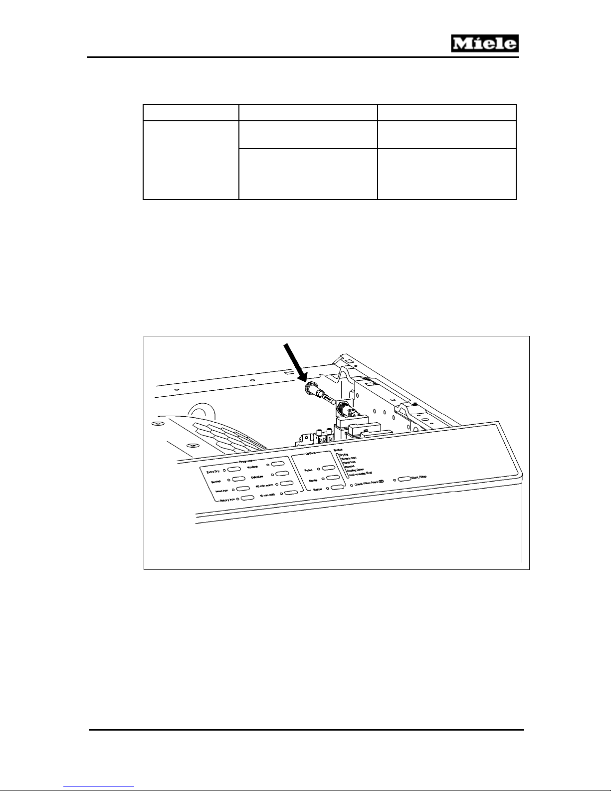
T 980x/T 982x
1 Technical Data
Electrical system
Table 100-1: Electrical System Data
Electric Heating Gas Heating
Dryer fuses (F2); 7 A T, 6.3
mm x 32 mm (0.25” x 1.25”)
Heater relays (1K1/1, 2K1/1,
3K1/1): single-anchor relays,
rating 11A; coil: 12VDC,
200Ω
4 Service
4.1 Fuse Replacement (T 980x only)
1. Disconnect the appliance from the power supply.
2. Remove the lid; see Section 010-4.1.
3. Unscrew the black fuse cap (see arrow, Figure 100-1) and remove the fuse.
4. Insert the new fuse into the black cap and screw the cap back into place.
Technical Information
--
Heater relays (1K1/1, 2K1/1)
Figure 100-1: Fuse Replacement
4.2 Heater Relay Removal
1. Disconnect the appliance from the power supply.
2. Remove the dryer lid; refer to Section 010-4.1.
3. Disconnect the electrical connections from the appropriate relay. (Relays
are located in front of the fuse; refer to Figure 100-1, if necessary.)
4. Press in on the locking tab and slide the relay forward to remove.
67
 Loading...