

Page 1
Installationsplan / Installation plan
Installatietekening
Plan d`installation
Piano di installazione
Plano de instalación
Plano de instalação
Σχέδιο εγκατάστασης
Asennusohje
Installasjonsplan
Installationsplan
G
PW 6321 G
Materialnummer / Mat. no.: 06 564 750
Änderungsstand / Version: 01
Datum Zeichnung / Drawing date: 05.10.2007
Datum Legende / Legend date: 05.10.2007
Page 2

Page 3
Page 4

Page 5

Page 6

Technical Datasheet
Washer-extractor:
Heating:
PW 6321
Gas (G)
Legend:
Circled, bold-type abbreviations:
Connection required
G
Machine connections:
Electrical
connection
Connection cable, min. cross-section mm² 5 × 1.5
With threaded cable grommet M 20 x 1.5
Frequency Hz 50
Rated load kW 4.7
Fuse rating A 3 × 16
Abbreviations surrounded by broken circle:
Connection optional or required, depending on model
1. Standard voltage (as supplied) V 3N AC 380 - 415
Plug and socket connection in accordance with IEC 60309
Gas connection Natural gas
Length of connection hose (supplied) mm 350
Liquid gas
On-site connection (Ermeto quick-release connector) DN 12
Min. connection pressure (may vary depending on
Length of connection hose (supplied) mm 350
Gas regulating valve is provided by Miele. A gas stopcock
See also installation instructions on gas-heated washer-
Connection thread (on site) Inch ½" internal thread
Nominal heat load kW 34
Min. connection pressure (may vary depending on
recommended to facilitate electrical safety tests.
Install mains isolator according to IEC 60947 on hard-wired
connection.
Wall socket or mains isolator must be accessible after
installation.
The use of an earth leakage circuit breaker (ELCB) is strongly
recommended. If an ELCB is fitted, it must be a Type B RCD
able to cope with rectified three-phase supplies.
If necessary, equipotential bonding with good galvanic contact
must be provided in accordance with all appropriate national
and local regulations.
country)
country)
must be provided on site.
extractors.
Local gas and plumbing regulations must be observed!
Pa 1700
Pa 2800 - 5750
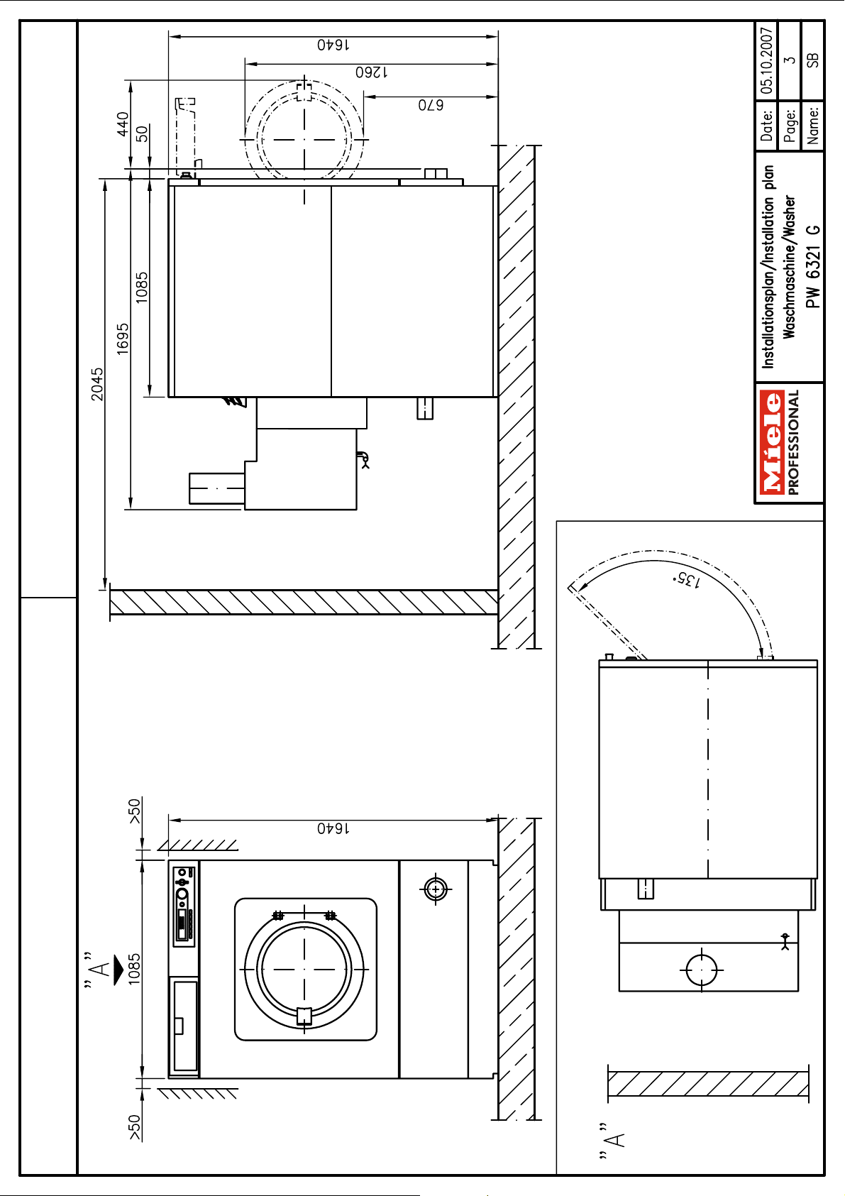
Installationsplan / Installation plan: PW 6321 G
Datum / Date: 05.10.2007 Seite / Page: 6
Page 7

Cold water
(soft water)
On-site connection thread according to DIN 44 991 Inch 1" external thread
Length of connection hose (parts supplied: 1 connection
Water requirements (average for 60°C programme)
Standard connection (with hot water connection) l/h Approx. 174
Min. flow pressure kPa 100
Max. pressure kPa 1000
Max. throughput (if hot water supply is not available) l/min 35.5 (80)
hose)
mm 1500
Increase alternative water type accordingly if one of water
Hot water
(soft water)
Max. throughput l/min 30
On-site connection thread according to DIN 44 991 Inch 1" external thread
Length of connection hose (parts supplied: 1 connection
Water requirements (average for 60°C programme)
Standard connection (with hot water connection) l/h Approx. 228
Cold water
(Hard water)
On-site connection thread according to DIN 44 991 Inch 1" external thread
Length of connection hose (parts supplied: 1 connection
Water requirements (average for 60°C programme)
Standard connection (with hot water connection) l/h Approx. 300
Waste gas Natural gas
Waste gas volume flow at nominal heat load g/s 32.1
Waste gas temperature at nominal heat load °C 110
CO2 concentration at nominal heat load % Approx. 4.0
Feed pressure at nominal heat load hPa -0.02
Liquid gas
Nominal heat load kW 34
Waste gas connection (Int. dia. × wall thickness × l) mm 150 x 1 x 275
Waste gas volume flow at nominal heat load g/s 35.3
Waste gas temperature at nominal heat load °C 100
CO2 concentration at nominal heat load % Approx. 4.0
Feed pressure at nominal heat load hPa -0.06
Atmospheric burner with integrated non-return device Type:
Nominal heat load kW 34
Waste gas connection (Int. dia. × wall thickness × l) mm 150 x 1 x 275
types is not available.
Max. temperature °C 70
Min. flow pressure kPa 100
Max. pressure kPa 1000
hose)
If no hot water supply, connect hose to cold water!
Min. flow pressure kPa 100
Max. pressure kPa 1000
Max. throughput l/min 40
hose)
If no raw water supply, connect hose to cold water!
B
11BS
See also installation instructions on gas-heated washerextractors.
Local gas and plumbing regulations must be observed!
mm 1500
mm 1500
Combustible and non-heat resistant materials should be kept
Drainage via
dump valve
Installationsplan / Installation plan: PW 6321 G
Datum / Date: 05.10.2007 Seite / Page: 7
at a safe distance from the gas supply line.
Max. temperature °C 95
Machine drain connection (d
On-site drain connection (d
Max. transient throughput l/min 200
Vented drainage required. If ventilation is insufficient, fit Miele
kit, Mat. no. 05238090.
Drain manifolds serving several machines must be of
sufficient cross-section.
× s × l) [DN 70] mm 75 × 1.9 × 110
ext
) [DN 70 sleeve] mm 75
int
Page 8

Foam
compensation
Machine must be bolted to the floor!
Fixing materials for floating screed floor to be provided on site
Machine data Width mm 1085
Depth mm 1695
Height mm 1640
Min. access width to installation site mm 1090
Minimum rear wall gap (measured to front of machine) mm 2045
Net weight kg 734
Dynamic floor load, max. N 9819
Static floor load, max. N Not yet available
Dynamic load, max. N Not yet available
Drum frequency, max. Hz 16.7
Average heat dissipation
Installation should only be carried out by authorised fitters in accordance with valid regulations!
Observe installation instructions when installing machine! All rights reserved! Dimensions in mm
4 × rawl plugs (Ø × length) mm 16 × 80
Excessive foaming may result in foam discharge through air
vent. In order to dispose of this foam, a drain with U tube can
be installed on site using conventional plumbing supplies. A
branch with an end cap should be provided for this purpose.
Without plinth Fittings (supplied)
4 × screws DIN 571 (Ø × length) mm 12 × 90
(dependent on ambient room temperature and programme
selected)
W Not yet available
Installationsplan / Installation plan: PW 6321 G
Datum / Date: 05.10.2007 Seite / Page: 8
 Loading...