

1
2
Produktgruppen 522, 592 Umbau- und Montageanweisung
1 von 30 M.-Nr. 07946040
28.09.2010 Diese Unterlagen dürfen ohne unsere Genehmigung weder vervielfältigt noch Dritten zugänglich gemacht werden. Eigentumsrechte vorbehalten.
PT 8251, PT 8251 COP, PT 8253, PT 8255, PT 8257, PT 8331, PT 8331 COP, PT 8333, PT 8335, PT 8337, UO 8250, UG 8250, UO 8330,
UG 8330
x
de
ni
it
Montageanweisung Unterbausockel UO 8250 / UO 8330,
UG 8250 / UG 8330
Montage-instructie sokkel
UO 8250 / UO 8330,
UG 8250 / UG 8330
Set di montaggio base
UO 8250 / UO 8330,
UG 8250 / UG 8330
en
da
es
Fitting instructions - Plinth
UO 8250 / UO 8330,
UG 8250 / UG 8330
Monteringsanvisning sokkel
UO 8250 / UO 8330,
UG 8250 / UG 8330
Instrucciones de montaje Zócalo
UO 8250 / UO 8330,
UG 8250 / UG 8330
fr
sv
am
Notice de montage de socle
UO 8250 / UO 8330,
UG 8250 / UG 8330
Monteringsanvisning sockel
UO 8250/UO 8330,
UG 8250/UG 8330
Installation Instructions Stand UO 8250/UO 8330,
UG 8250/UG 8330
3
4
5
6
Produktgruppen 522, 592 Umbau- und Montageanweisung
2 von 30 M.-Nr. 07946040
28.09.2010 Diese Unterlagen dürfen ohne unsere Genehmigung weder vervielfältigt noch Dritten zugänglich gemacht werden. Eigentumsrechte vorbehalten.
x

Produktgruppen 522, 592 Umbau- und Montageanweisung
3 von 30 M.-Nr. 07946040
28.09.2010 Diese Unterlagen dürfen ohne unsere Genehmigung weder vervielfältigt noch Dritten zugänglich gemacht werden. Eigentumsrechte vorbehalten.
de
Benötigte Teile
x
Anzahl M.-Nr. Benennung
1 07761970 Montagesatz Sockel UO 8250
oder
1 07762000 Montagesatz Sockel UO 8330
oder
1 07761950 Montagesatz Sockel UG 8250
oder
1 07761990 Montagesatz Sockel UG 8330
Hinweis
Diese Umbauarbeiten dürfen grundsätzlich nur von einer Elektrofachkraft (fachliche Ausbildung, Fachkenntnisse und Facherfahrungen,
zeitnahe berufliche Tätigkeit) unter Berücksichtigung der gültigen Sicherheitsbestimmungen durchgeführt werden.
Für die Inbetriebnahme, Instandsetzung, Änderung, Prüfung und Wartung elektrischer Geräte sind die entsprechenden gesetzlichen
Grundlagen, Unfallverhütungsvorschriften, die gültigen Normen, die der Sicherheit dienen, sowie die am Aufstellungsort gültigen
Vorschriften der Energieversorgungsunternehmen zu beachten.
Hinweis
Wartungsarbeiten an Gasgeräten dürfen, außer durch das Gasversorgungsunternehmen und Vertragsinstallationsunternehmen, nur von
Wartungsunternehmen ausgeführt werden, die den Festlegungen des DVGW-Arbeitsblattes G 676 entsprechen. Wartungsarbeiten an
Gasgeräten dürfen grundsätzlich nur von einer Fachkraft unter Berücksichtigung der gültigen Sicherheitsbestimmungen durchgeführt
werden.
Bevor Wartungsarbeiten am Gerät ausgeführt werden, ist eine Trennung vom Gasnetz unbedingt erforderlich.
Gefahr!
Auch bei ausgeschaltetem Gerät kann Netzspannung an Bauteilen anliegen!
Deshalb ist, bevor Wartungsarbeiten, Instandsetzungsarbeiten oder Änderungen am Gerät durchgeführt werden, eine sichere
Netztrennung von allen aktiven, spannungsführenden Leitungen sowie anschließend eine Messung der Spannungsfreiheit erforderlich!
Grundsätzlich muss eine allgemeine Sichtprüfung und Gefährdungsbeurteilung durchgeführt werden.
Ein nicht fachgerechten Änderung kann zu einer Gefährdung führen (Brand, elektrischer Schlag usw.).
Gefahr!
Die Schutzleiterfunktion kann durch einen fehlerhaften Gehäusezusammenbau außer Kraft gesetzt werden.
Die Schutzleiterfunktion ist bei Montage der Gehäuseteile wieder herzustellen.
Elektrische Sicherheitsprüfung durchführen. (Sichtprüfung und Messung des ordnungsgemäßen Schutzleiterwiderstandes).
Gefahr!
Bei der Montage dürfen berührbare leitfähige Teile, die nicht am Schutzleiter angeschlossen sind, keine Schutzleiterverbindung haben
(verstärkte, doppelte Isolierung).
Der Nachweis ist durch Messen des ordnungsgemäßen Isolationswiderstandes und Berührungsstromes nachzuweisen.

Produktgruppen 522, 592 Umbau- und Montageanweisung
4 von 30 M.-Nr. 07946040
28.09.2010 Diese Unterlagen dürfen ohne unsere Genehmigung weder vervielfältigt noch Dritten zugänglich gemacht werden. Eigentumsrechte vorbehalten.
Gefahr!
Verletzungsgefahr bei der Montage
• Stromschlaggefahr. Vor Wartungs- und Instandsetzungsarbeiten an der Maschine, alle spannungsführenden Leitungen vom Netz
trennen.
• Den Sockel nur an Waschautomaten montieren, die nicht installiert sind. Deinstallation siehe Maschinen-Gebrauchsanweisung.
• Quetschgefahr. Rutschfeste Handschuhe und Sicherheitsschuhe tragen.
• Quetschgefahr. Darauf achten, dass keine Körperteile, insbesondere Hände und Füße, unter oder zwischen die Maschinen
gelangen.
• Unfallgefahr. Sicherstellen, dass während der Montagearbeiten keine Personen oder Tiere in den Arbeitsbereich gelangen
können.
• Verletzungsgefahr, insbesondere Verletzung der Wirbelsäule. Das Gewicht der Maschine im Verhältnis zur eigenen körperlichen
Kraft beachten. Gewichtsangabe der Maschine siehe Maschinen-Gebrauchsanweisung.
Kippgefahr. Verletzungsgefahr durch fehlerhafte Montage
• Die Maschinen stets mit dem Sockel verschrauben.
• Bei Einzelaufstellung den Sockel mit dem Zubehör Fundamentbefestigung M.-Nr. 01497252 auf dem Fußboden befestigen. Im
Umbausatz enthalten.
• Bei der Bodenbefestigung vier Sockelfüße am Boden befestigen.
Hinweis
Den Sockel ausschließlich für folgende Miele-Geräte verwenden:
• UO 8250 / UG 8250 = PT 8251, PT 8251 COP, PT 8253, PT 8255, PT 8257
UO 8330 / UG 8330 = PT 8331, PT 8331 COP, PT 8333, PT 8335, PT 8337
Hinweis
Erforderliches Werkzeug:
• Wasserwaage zum lotrechten und waagerechten Ausrichten des Sockels
• 1 x Bohrmaschine
• 1 x Bohrer Ø 12 mm
• 1 x Maulschlüssel Schlüsselweite 13 mm für Mutter M8
• 2 x Maulschlüssel Schlüsselweite 10 mm für Mutter M6
• 1 x Schraubendreher Torx 20
Hinweis
Der Montagesatz Sockel UO 8250 M.-Nr. 07761970 oder der Montagesatz Sockel UO 8330 M.-Nr. 07762000 bestehen aus:
• 1 x Sockel UO 8250 oder 1 Sockel UO 8330
• 1 x Zubehör Fundamentbefestigung mit Schachtel: 4 x Spannlasche / 8 x Scheibe verzinkt B6,4 / 4 x Sechskantschraube M6 x 20 /
4 x Sechskantmutter M6 / 4 x Dübel S12 / 4 x Scheibe 8,4 / 4 x Sechskant-Holzschraube 8 x 65 / 20 x Unterlegblech / 8 x Scheibe
38 mm Ø
• 1 x Zubehör Begleitschriften mit dieser Montageanweisung und Inbetriebnahmekarte. Diese Umbau- und Montageanweisung
heißt “Montageanweisung Unterbausockel UO 8250 / UO 8330, UG 8250 / UG 8330”.
Hinweis
Der Montagesatz Sockel UG 8250 M.-Nr.07761950 oder der Montagesatz Sockel UG 8330 M.-Nr. 07761990 bestehen aus:
• 1 x Sockel UO 8250 oder 1 Sockel UO 8330, 1 x Vorderwand, 2 x Seitenwand, 8 x Linsenschraube 4,8 x 9,5 und 4 x Gummipuffer,
beim Montagesatz Sockel UG 8250 M.-Nr. 07761950
• 1 x Zubehör Fundamentbefestigung mit Schachtel: 4 x Spannlasche / 8 x Scheibe verzinkt B6,4 / 4 x Sechskantschraube M6 x 20 /
4 x Sechskantmutter M6 / 4 x Dübel S12 / 4 x Scheibe 8,4 / 4 x Sechskant-Holzschraube 8 x 65 / 20 x Unterlegblech / 8 x Scheibe
38 mm Ø
• 1 x Zubehör Begleitschriften mit dieser Montageanweisung und Inbetriebnahmekarte. Diese Umbau- und Montageanweisung
heißt “Montageanweisung Unterbausockel UO 8250 / UO 8330, UG 8250 / UG 8330”.
Liste der Abbildungen:
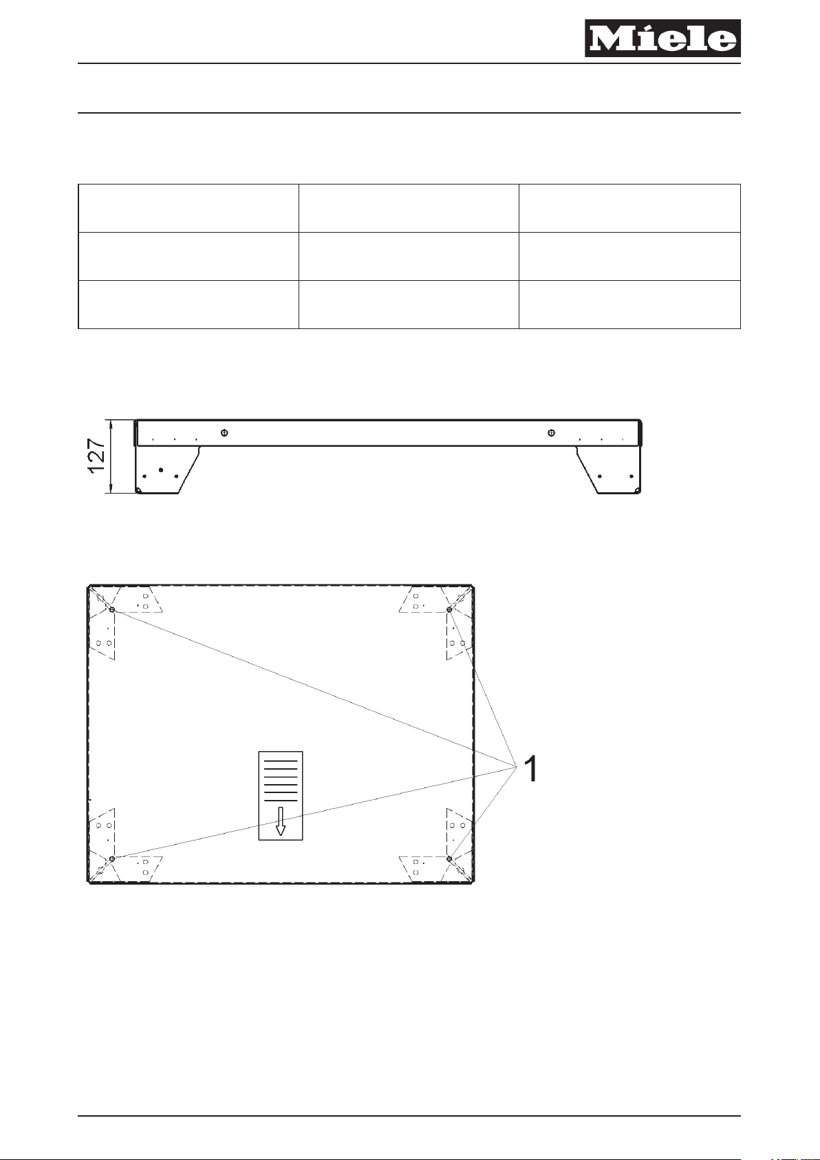
– Abb. 1, Sockelhöhe
– Abb. 2, Bohrungen Bodenbefestigung
– Abb. 3, Bohrungsmaß Bodenbefestigung
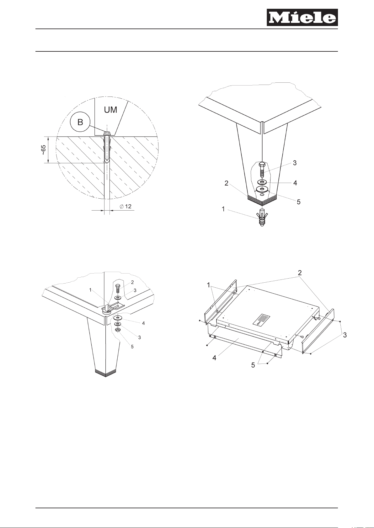
– Abb. 4, Montage Bodenbefestigung
Produktgruppen 522, 592 Umbau- und Montageanweisung
5 von 30 M.-Nr. 07946040
28.09.2010 Diese Unterlagen dürfen ohne unsere Genehmigung weder vervielfältigt noch Dritten zugänglich gemacht werden. Eigentumsrechte vorbehalten.
– Abb. 5, Montage Spannlasche
– Abb. 6, Sockel UG 8250 / UG 8330
x
Kürzel Erklärung
UM Unterbau Miele, Sockel
B Bodenbefestigung
Tabelle 1: Legende Abkürzungen
– Gegebenenfalls den Gasanschluss schließen.
– Die Maschine vom bestimmungsgemäßen Elektroanschluss und gegebenenfalls vom Gasnetz trennen und gegen
Wiedereinschalten sichern.
– Sockel positionieren und die Bohrlöcher anzeichnen, siehe Abb. 2, Pos.1.
x
Hinweis
Mindestabstände aus dem Installationsplan beachten.
Seitlicher Wandabstand der Maschine mindestens 10 mm.
– 4 Bohrungen mit 12 mm Ø ca. 65 mm tief in den Fußboden einbringen, siehe Abb. 3.
– 4 Dübel S12 bündig in die Bohrungen schieben, siehe Abb. 4, Pos. 1.
– Mit Unterlegblechen (Abb. 4, Pos. 2) und Wasserwaage den Sockel lotrecht und waagerecht ausrichten.
– Sockel mit 4 Sechskant-Holzschrauben 8 x 65 (Abb. 4, Pos. 3), Scheiben 8,4 (Abb. 4, Pos. 4) und Scheiben 38 mm Ø
(Abb. 4, Pos. 5) auf dem Fußboden festschrauben.
– Maschine auf den Sockel stellen.
x
Gefahr!
Verletzungsgefahr, insbesondere Verletzung der Wirbelsäule. Das Gewicht der Maschine im Verhältnis zur eigenen körperlichen Kraft
beachten. Gewichtsangabe der Maschine siehe Maschinen-Gebrauchsanweisung.
Quetschgefahr. Darauf achten, dass keine Körperteile, insbesondere Hände und Füße, unter oder zwischen die Maschine gelangen.
– 4 Spannlaschen (Abb. 5, Pos.1) über die Maschinenfüße schieben.
– 4 Sechskantschrauben M6 (Abb. 5, Pos. 2) mit Scheiben verzinkt B6,4 (Abb. 5, Pos. 3) von oben durch die vorhandenen Bohrungen
stecken.
– 4 Spannlaschen von unten mit Scheiben 38 mm Ø Abb. 5, Pos. 4), Scheiben verzinkt B6,4 Abb. 5, Pos. 3) und Sechskantmuttern
M6 Abb. 5, Pos. 5) von unten festschrauben.
x
Gefahr!
Kippgefahr und Absturzgefahr! Die Sockelbefestigung am Boden und die Maschinenbefestigung am Sockel ist zwingend erforderlich!
Hinweis
Abluftrohr in der Höhe anpassen.
Hinweis
Befestigungsmaterial für schwimmenden Estrich ist bauseits zu erbringen.
Sockel UG 8250 / UG 8330
– 4 Gummipuffer seitlich in den Sockel stecken, siehe Abb. 6, Pos. 1.
– 2 Seitenwände in die Schlitze der Trocknergrundplatte stecken Abb. 6, Pos. 2 und mit Linsenschraube 4,8 x 9,5 festschrauben,
siehe Abb. 6, Pos. 3.
– Vorderwand Abb. 6, Pos. 4 mit Linsenschraube 4,8 x 9,5 festschrauben, siehe Abb. 6, Pos. 5.
– Eine Sicherheitsprüfung durchführen.
– Die Maschine an dem bestimmungsgemäßen Elektroanschluss anschließen und gegebenenfalls mit dem Gasnetz verbinden.
de

Produktgruppen 522, 592 Umbau- und Montageanweisung
6 von 30 M.-Nr. 07946040
28.09.2010 Diese Unterlagen dürfen ohne unsere Genehmigung weder vervielfältigt noch Dritten zugänglich gemacht werden. Eigentumsrechte vorbehalten.
en
Parts required
x
Quantity Mat. no. Designation
1 07761970 Fitting kit - Plinth UO 8250
or
1 07762000 Fitting kit - Plinth UO 8330
or
1 07761950 Fitting kit - Plinth UG 8250
or
1 07761990 Fitting kit - Plinth UG 8330
Note
This service and repair work should only be carried out by a suitably qualified electrician (with specialist training, knowledge and
experience, and recent related work experience) in accordance with all appropriate local and national safety regulations.
Servicing, modification, testing and maintenance of electrical appliances should only be carried out in accordance with all appropriate
legal requirements, accident prevention regulations and valid standards. All regulations of the appropriate utility supply companies and
standards relating to safety (not limited to electrical safety) are to be complied with.
Note
Service and repair work on gas machines should only be carried out by suitably qualified persons in accordance with all appropriate local
and national safety regulations. Ensure all special regulations applying to gas installations are also complied with.
Before any service work is commenced, the machine must be disconnected from the gas mains.
Danger!
Even with the machine switched off, mains voltage may be applied to some components.
Before any service work is commenced, the machine must be disconnected from the mains. Suitable measurements must be made to
ensure that this is the case.
A general visual check should always be carried out.
Incorrect conversion or service work can be dangerous (risk of fire, electric shock, etc.).
Danger!
Correct earthing function can be deactivated if casing parts are incorrectly assembled.
Correct earthing function must be ensured when refitting the casing.
Carry out appropriate electrical safety checks. (Including visual check and earth resistance check.)
Danger!
During fitting, all accessible conductive parts that are not connected to the earth must not have any link to earth (strengthened double
insulation).
To confirm this, insulation resistance and touch current measurements must be carried out.

Produktgruppen 522, 592 Umbau- und Montageanweisung
7 von 30 M.-Nr. 07946040
28.09.2010 Diese Unterlagen dürfen ohne unsere Genehmigung weder vervielfältigt noch Dritten zugänglich gemacht werden. Eigentumsrechte vorbehalten.
Danger!
Risk of injury during fitting.
• Risk of electric shock. Before any service work is commenced, the machine must be disconnected from the mains.
• Fitting can only be carried out with the washing machine or tumble dryer not installed. For deinstallation, see the appropriate
operating instructions.
• Risk of crushing. Wear slip-proof working gloves and safety shoes.
• Risk of crushing. When carrying out work, ensure that parts of the body, especially the hands and feet are not positioned under or
between machines.
• Risk of accident. Ensure that children or pets cannot access the work area while fitting work is being carried out.
• Risk of injury, particularly to the back. The relation of the weight of the machine to the physical strength of the technician must be
taken into account. For machine weight details, see the appropriate operating instructions.
Risk of toppling over. Risk of injury due to incorrect fitting.
• Always bolt the machine to the plinth.
• With a single machine installation, secure the plinth to the floor with the fastening accessory, Mat. no. 01497252, supplied with the
kit. This is supplied with the kit.
• With floor fastening, secure all four plinth feet.
Note
The plinth may only be used with the following Miele models:
• UO 8250 / UG 8250 = PT 8251, PT 8251 COP, PT 8253, PT 8255, PT 8257
UO 8330 / UG 8330 = PT 8331, PT 8331 COP, PT 8333, PT 8335, PT 8337
Note
Tools required:
• Spirit level for plinth levelling
• 1 x Drill
• 1 x Drill bit Ø 12 mm
• 1 x Open spanner 13 mm for M8 nut
• 2 x Open spanner 10 mm for M6 nut
• 1 x Torx 20 screwdriver
Note
The fitting kit - Plinth UO 8250 Mat. no. 07761970, or fitting kit - Plinth UG 8330, Mat. no. 07762000, contains the following:
• 1 x Plinth UO 8250 or UO 8330
• 1 x Floor fastening accessory pack containing the following: 4 x Clamp, 8 x Galvanised washer B6.4, 4 x Bolt M6 x 20, 4 x Nut M6,
4 x Rawl plug S12, 4 x Washer 8.4, 4 x Hexagon head wood screw 8 x 65, 20 x Spacer plate, 8 x Washer 38 mm Ø
• 1 x Information sheet with these instructions and commissioning card. These fitting instructions are called “Fitting instructions Plinth UO 8250 / UO 8330, UG 8250 / UG 8330”.
Note
The fitting kit - Plinth UO 8250 Mat. no. 07761950, or fitting kit - Plinth UG 8330, Mat. no. 07761990, contains the following:
• 1 x Plinth UO 8250 or UO 8330,1 x Front panel, 2 x Side panel, 8 x Raised-head screw 4.8 x 9.5 and 4 x Rubber bumpers with
fitting kit - Plinth UG 8250, Mat. no. 07761950.
• 1 x Floor fastening accessory pack containing the following: 4 x Clamp, 8 x Galvanised washer B6.4, 4 x Bolt M6 x 20, 4 x Nut M6,
4 x Rawl plug S12, 4 x Washer 8.4, 4 x Hexagon head wood screw 8 x 65, 20 x Spacer plate, 8 x Washer 38 mm Ø
• 1 x Information sheet with these instructions and commissioning card. These fitting instructions are called “Fitting instructions Plinth UO 8250 / UO 8330, UG 8250 / UG 8330”.
List of illustrations:
– Fig. 1: Plinth height
– Fig. 2: Floor fastening holes
– Fig. 3: Floor fastening hole dimensions
– Fig. 4: Floor fastening
– Fig. 5: Clamp fitting
– Fig. 6: Plinth UG 8250 / UG 8330

Produktgruppen 522, 592 Umbau- und Montageanweisung
8 von 30 M.-Nr. 07946040
28.09.2010 Diese Unterlagen dürfen ohne unsere Genehmigung weder vervielfältigt noch Dritten zugänglich gemacht werden. Eigentumsrechte vorbehalten.
x
Abbreviation Explanation
UM Miele plinth
B Floor fastening
Table 1: Abbreviation legend
– Close the gas stopcock if applicable.
– Disconnect the machine from the electric mains supply provided in accordance with all relevant regulations and the gas supply
(if applicable), and ensure utilities cannot be switched on again in error.
– Place the plinth in position and mark the hole positions, see Fig. 2, Pos.1.
x
Note
Take care to comply with the minimum spacings given in the installation plan.
The gap between the machine and a wall at the side must be at least 10 mm.
– Drill 4 holes 12 mm Ø approx. 65 mm deep in the floor as shown, Fig. 3.
– Insert 4 S12 Rawl plugs flush in the holes, Fig. 4, Pos. 1.
– Fit spacer plates, Fig. 4, Pos. 2, as appropriate and use the spirit level to level the plinth.
– Secure the plinth with four 8 x 65 hexagon head wood screws, Fig. 4, Pos. 3, 8.4 washers, Fig. 4, Pos. 4, and 38 mm Ø washers,
Fig. 4, Pos. 5, to the floor.
– Place the machine on the plinth.
x
Danger!
Risk of injury, particularly to the back. The relation of the weight of the machine to the physical strength of the technician must be taken
into account. For machine weight details, see the appropriate operating instructions.
Risk of crushing. When carrying out work, ensure that parts of the body, especially the hands and feet are not positioned under or
between machines.
– Fit 4 clamps, Fig. 5, Pos.1, over the machine feet.
– Insert four M6 bolts, Fig. 5, Pos. 2, with B6.4 galvanised washers, Fig. 5, Pos. 3, from above through the existing holes.
– Secure the 4 clamps from below with 38 mm Ø washers, Fig. 5, Pos. 4, B6.4 galvanised washers, Fig. 5, Pos. 3, and M6 nuts,
Fig. 5, Pos. 5, tightened from below.
x
Danger!
Risk of toppling and falling! It is absolutely essential to secure the plinth to the floor and the machine to the plinth.
Note
Match the height of the vent duct.
Note
Fixing materials for a floating screed floor are to be provided on site.
Plinth UG 8250 / UG 8330
– Fit the 4 rubber bumpers in the plinth sides, Fig. 6, Pos.1.
– Fit the 2 side panels in the slots in the dryer base plate, Fig. 6, Pos. 2, and secure them with the raised-head screws 4.8 x 9.5,
Fig. 6, Pos. 3.
– Fit the front panel Fig. 6, Pos. 4, and secure it with the raised-head screws 4.8 x 9.5, Fig. 6, Pos. 5.
– Carry out appropriate safety checks.
– Reconnect the machine to the electric mains supply provided in accordance with all relevant regulations, and the gas supply
(if applicable).
en

Produktgruppen 522, 592 Umbau- und Montageanweisung
9 von 30 M.-Nr. 07946040
28.09.2010 Diese Unterlagen dürfen ohne unsere Genehmigung weder vervielfältigt noch Dritten zugänglich gemacht werden. Eigentumsrechte vorbehalten.
fr
Pièces nécessaires
x
Nombre Mat.-Nr. Désignation
1 07761970 Jeu de montage socle UO 8250
ou
1 07762000 Jeu de montage socle UO 8330
ou
1 07761950 Jeu de montage socle UG 8250
ou
1 07761990 Jeu de montage socle UG 8330
Remarque
Les travaux d'adaptation doivent être effectués exclusivement par un technicien qualifié (c'est à dire ayant suivi une formation
spécifique et disposant de connaissances et d'expériences récentes dans le domaine) respectant les prescriptions de sécurité en
vigueur.
La réglementation en vigueur, les prescriptions de prévention des accidents, les normes applicables de sécurité sur le lieu d'installation
ainsi que les prescriptions de la compagnie d'électricité doivent impérativement être respectées pour la mise en service, la réparation,
la modification, le contrôle et l'entretien des appareils électriques.
Remarque
Outre la compagnie de gaz ou l'installateur agréé, seule une société de maintenance répondant aux critères définis dans la
réglementation sur le gaz peut procéder aux interventions sur les appareils gaz. Les travaux doivent être effectués exclusivement par un
technicien qualifié dans le respect des consignes de sécurité en vigueur.
Avant toute maintenance, débrancher impérativement l'appareil du réseau de gaz.
Danger !
Même si l'appareil est déconnecté, les composants peuvent présenter une tension résiduelle.
C'est pourquoi avant d'effectuer des travaux d'entretien ou de réparation ou encore des modifications sur l'appareil, il est nécessaire de
débrancher tous les câbles actifs et sous tension et d'effectuer une mesure pour s'assurer de l'absence de tension résiduelle !
Un contrôle visuel général et une évaluation des risques doivent impérativement être effectués.
Une modification non effectuée dans les règles peut avoir des conséquences dangereuses (incendie, électrocution, etc.)
Danger !
En cas de remontage de la carrosserie incorrect, le fonctionnement de la mise à la terre de l'appareil risque d'être désactivé.
Le fonctionnement de la mise à la terre doit être assuré après le montage des pièces de la carrosserie.
Effectuer un contrôle de sécurité électrique. (Contrôle visuel et mesure de la résistance de terre afin de vérifier qu'elle est correcte).
Danger !
Lors du montage, les pièces conductrices accessibles qui ne sont pas raccordées à la terre ne doivent pas être reliées à la terre
(isolation renforcée, double).
Ceci doit être vérifié en mesurant la résistance d'isolation et la résistance de contact.

Produktgruppen 522, 592 Umbau- und Montageanweisung
10 von 30 M.-Nr. 07946040
28.09.2010 Diese Unterlagen dürfen ohne unsere Genehmigung weder vervielfältigt noch Dritten zugänglich gemacht werden. Eigentumsrechte vorbehalten.
Danger !
Risque de blessure lors du montage
• Risque de décharge électrique. Débrancher tous les câbles sous tension avant d'effectuer les travaux d'entretien et de réparation.
• Ne monter le socle que sur les lave-linge non installés. Désinstallation : voir le mode d'emploi de la machine.
• Risque d'écrasement. Utiliser des gants antidérapants et des chaussures de sécurité.
• Risque d'écrasement. Ne pas mettre de parties du corps, en particulier les mains ou les pieds, sous ou entre les machines.
• Risque d'accident. Assurez-vous que les enfants ou les animaux ne peuvent pas pénétrer dans la pièce où les travaux sont
effectués pendant le montage.
• Risque de blessure, en particulier au niveau de la colonne vertébrale. Prenez en compte le poids des appareils et ne surestimez
pas votre force. Indication du poids de la machine, voir mode d'emploi.
Risque de basculement. Risque de blessure en cas de montage incorrect
• Toujours visser les machines sur le socle.
• En cas d'installation d'une seule machine sur socle, fixer le socle au sol avec le jeu de montage fixation au sol M.-Nr. 01497252.
Fourni avec le jeu de montage.
• Pour la fixation au sol, fixer les quatre pieds au sol.
Remarque
N'utiliser le socle qu'avec les appareils Miele suivants :
• UO 8250 / UG 8250 = PT 8251, PT 8251 COP, PT 8253, PT 8255, PT 8257
UO 8330 / UG 8330 = PT 8331, PT 8331 COP, PT 8333, PT 8335, PT 8337
Remarque
Outils nécessaires :
• Niveau pour l'installation d'aplomb du socle
• 1 x perceuse
• 1 x foret Ø 12 mm
• 1 x clé à fourche ouverture de 13 mm pour écrou M8
• 2 x clés à fourche ouverture de 10 mm pour écrou M6
• 1 x tournevis Torx 20
Remarque
Le jeu de montage socle UO 8250 M.-Nr. 07761970 ou le jeu de montage socle UO 8330 M.-Nr. 07762000 se compose de :
• 1 x socle UO 8250 ou 1 socle UO 8330
• 1 x accessoire fixation au sol avec boîte : 4 x pattes de fixation / 8 x rondelles galvanisées B6,4 / 4 x vis à six pans M6 x 20 / 4 x
écrous à six pans M 6 / 4 x chevilles S12 / 4 x rondelles 8,4 / 4 vis à bois à six pans 8 x 65 / 20 x cales / 8 x rondelles 38 mm Ø
• 1 x dossier de documents relatifs aux produits avec la présente notice de montage et la carte de mise en service. La présente
notice d'adaptation et de montage "Notice de montage de socle UO 8250 / UO 8330, UG 8250 / UG 8330".
Remarque
Le jeu de montage socle UO 8250 M.-Nr. 07761950 ou le jeu de montage socle UG 8330 M.-Nr. 07761990 se compose de :
• 1 x socle UO 8250 ou 1 socle UO 8330,1 x façade, 2 x parois latérales, 8 x vis à tête bombée 4,8 x 9,5 et 4 x amortisseurs
caoutchouc, dans le jeu de montage de socle UG 8250 M.-Nr. 07761950
• 1 x accessoire fixation au sol avec boîte : 4 x pattes de fixation / 8 x rondelles galvanisées B6,4 / 4 x vis à six pans M6 x 20 / 4 x
écrous à six pans M 6 / 4 x chevilles S12 / 4 x rondelles 8,4 / 4 vis à bois à six pans 8 x 65 / 20 x cales / 8 x rondelles 38 mm Ø
• 1 x dossier de documents relatifs aux produits avec la présente notice de montage et la carte de mise en service. La présente
notice d'adaptation et de montage "Notice de montage de socle UO 8250 / UO 8330, UG 8250 / UG 8330".
Liste des croquis :
– Croquis 1, hauteur socle
– Croquis 2, perçages de fixation au sol
– Croquis 3, cotes des perçages de fixation au sol
– Croquis 4, montage du passage de câble
– Croquis 5, montage patte de fixation
– Croquis 6, socle UG 8250 / UG 8330

Produktgruppen 522, 592 Umbau- und Montageanweisung
11 von 30 M.-Nr. 07946040
28.09.2010 Diese Unterlagen dürfen ohne unsere Genehmigung weder vervielfältigt noch Dritten zugänglich gemacht werden. Eigentumsrechte vorbehalten.
x
Abréviation Explication
UM Socle Miele
B Fixation au sol
Tableau 1: Légende abréviations
– Fermer le robinet de gaz le cas échéant.
– Débrancher la machine du branchement électrique conforme et le cas échéant du réseau de gaz et protéger contre une remise en
marche accidentelle.
– Positionner le socle et dessiner les perçages, voir croquis 2, pos. 1.
x
Remarque
Respecter les distances minimum du schéma d'installation.
Distance latérale avec la machine de 10 mm minimum.
– Effectuer 4 perçages de 12 mm de Ø et de 65 mm de profondeur dans le sol, voir croquis 3
– Insérer 4 chevilles S12 au ras du sol dans les perçages, voir croquis 4, pos. 1
– Disposer le socle d'aplomb verticalement et horizontalement (croquis 4, pos. 2) à l'aide des cales et du niveau à bulle.
– Visser le socle avec les vis à bois à six pans 8 x 65 (croquis 4, pos. 3), les rondelles 8,4 (croquis 4, pos. 4) et les rondelles 38 mm Ø
(croquis 4, pos. 5) sur le sol et serrer
– Poser la machine sur le socle.
x
Danger !
Risque de blessure, en particulier au niveau de la colonne vertébrale. Prenez en compte le poids des appareils et ne surestimez pas
votre force. Indication du poids de la machine, voir mode d'emploi.
Risque d'écrasement. Ne pas mettre de parties du corps, en particulier les mains ou les pieds, sous ou entre les machines.
– Poser les 4 pattes de fixation (croquis 5, pos. 1) sur les pieds de machine.
– Insérer les 4 vis M6 (croquis 5, pos. 2) avec rondelles galvanisées B6,4 (croquis 5, pos. 3) par le haut dans les perçages.
– Visser les 4 pattes de fixation par le bas avec les rondelles 38 mm Ø (croquis 5, pos. 4), rondelles galvanisées B6,4
(croquis 5, pos. 3) et écrous six pans M6 croquis 5, pos. 5.
x
Danger !
Risque de basculement et de chute ! La fixation de socle au sol et la fixation de la machine au socle sont obligatoires !
Remarque
Adapter le tuyau d'évacuation en hauteur.
Remarque
Le matériel de fixation pour parquet flottant doit être fourni par l'exploitant.
Socle UG 8250 / UG 8330
– Enfoncer 4 amortisseurs caoutchouc dans le socle, voir croquis 6, pos.1.
– Poser 2 parois latérales dans les fentes de la tôle de fond du sèche-linge croquis 6, pos. 2 et visser à fond avec les vis à tête
bombée 4,8 x 9,5, voir croquis 6, pos. 3.
– Visser la façade croquis 6, pos. 4 avec les vis à tête bombée 4,8 x 9,5, voir croquis 6, pos. 5.
– Effectuer un contrôle de sécurité.
– Relier la machine à un raccordement électrique conforme et le cas échant rebrancher le gaz également.
fr

Produktgruppen 522, 592 Umbau- und Montageanweisung
12 von 30 M.-Nr. 07946040
28.09.2010 Diese Unterlagen dürfen ohne unsere Genehmigung weder vervielfältigt noch Dritten zugänglich gemacht werden. Eigentumsrechte vorbehalten.
ni
Benodigde onderdelen
x
aantal Mat.-nr. Benaming
1 07761970 Montageset sokkel UO 8250
of
1 07762000 Montageset sokkel UO 8330
of
1 07761950 Montageset sokkel UG 8250
of
1 07761990 Montageset sokkel UG 8330
Opmerking
Deze ombouwwerkzaamheden mogen in principe alleen door een vakman, met inachtneming van alle geldende
veiligheidsvoorschriften worden uitgevoerd.
Voor inbedrijfstelling, reparatie, wijziging, controle en onderhoud van elektrische apparaten dient men de desbetreffende wetten,
veiligheidsvoorschriften en de geldende normen in acht te nemen.
Opmerking
Onderhoudswerkzaamheden aan gasapparaten mogen, behalve door het energiebedrijf en gecontracteerde installatiebedrijven, alleen
door erkende onderhoudsbedrijven uitgevoerd worden. Onderhoudswerkzaamheden mogen in principe alleen door een vakman, met
inachtneming van alle geldende veiligheidsvoorschriften worden uitgevoerd.
Voordat er onderhoudswerkzaamheden aan het apparaat uitgevoerd worden, dient het apparaat beslist van het gasnet
losgekoppeld te worden.
Pas op!
Ook als het apparaat uitgeschakeld is, kunnen onderdelen onder spanning staan!
Daarom is het noodzakelijk, voordat er onderhouds- en reparatiewerkzaamheden of wijzigingen aan het apparaat plaatsvinden, alle
actieve kabels, die onder spanning staan, spanningsvrij te maken en vervolgens te meten of de kabels spanningsvrij zijn!
Er dient een algemene optische controle en een risicobeoordeling plaats te vinden.
Een niet deskundige ingreep kan gevaarlijk zijn (brand, elektrische schok enz.).
Pas op!
De aarddraad kan door een verkeerde montage van was- en droogautomaten buiten werking gesteld worden.
De aarddraad moet bij de montage van het huis weer in werking gesteld worden.
Controleer de elektrische veiligheid. (Optische controle en meting van de aarddraadweerstand).
Pas op!
Bij de montage mogen aanraakbare geleidende onderdelen, die niet op de aarddraad aangesloten zijn, geen aarddraadverbinding
hebben (versterkte, dubbele isolatie).
Dit kan bewezen worden door de correcte isolatieweerstand en de contactstroom te meten.

Produktgruppen 522, 592 Umbau- und Montageanweisung
13 von 30 M.-Nr. 07946040
28.09.2010 Diese Unterlagen dürfen ohne unsere Genehmigung weder vervielfältigt noch Dritten zugänglich gemacht werden. Eigentumsrechte vorbehalten.
Pas op!
Gevaar voor verwondingen bij de montage
• Gevaar voor elektrische schok. Voordat u onderhouds- en reparatiewerkzaamheden aan het apparaat uitvoert, dient u alle kabels,
waarop spanning staat, spanningsvrij te maken.
• De sokkel alleen op apparaten monteren, die niet geïnstalleerd zijn. Voor de de-installatie zie de gebruiksaanwijzing van het
apparaat.
• Vingers kunnen bekneld raken. Draag stroeve handschoenen en veiligheidsschoenen.
• Vingers kunnen bekneld raken. Let erop, dat er geen lichaamsdelen, in het bijzonder handen en voeten, onder of tussen de
apparaten komen.
• Gevaarlijk. Zorg ervoor, dat tijdens de montagewerkzaamheden geen mensen of dieren in de buurt kunnen komen.
• Gevaar voor verwonding, met name beschadiging van de wervelkolom. Let op het gewicht van de apparaten in verhouding tot de
eigen fysieke kracht. Het gewicht van het apparaat wordt in de gebruiksaanwijzing vermeld.
Het apparaat kan kantelen. Gevaar voor verwonding door verkeerde montage
• Schroef de apparaten altijd op de sokkel vast.
• Als de sokkel alleen opgesteld wordt, maak deze dan aan de vloer vast met de montageset vloerbevestiging mat.-nr. 01497252.
Deze bevindt zich in de ombouwset.
• Zet bij de bevestiging op de bodem de vier voeten van de sokkel op de bodem vast.
Opmerking
De sokkel kan alleen voor de volgende apparaten gebruikt worden:
• UO 8250 / UG 8250 = PT 8251, PT 8251 COP, PT 8253, PT 8255, PT 8257
UO 8330 / UG 8330 = PT 8331, PT 8331 COP, PT 8333, PT 8335, PT 8337
Opmerking
Benodigd gereedschap:
• Waterpas voor het waterpas afstellen van de sokkel
• 1 x boormachine
• 1 x boortje Ø 12 mm
• 1 x steeksleutel sleutelbreedte 13 mm voor moer M8
• 2 x steeksleutel sleutelbreedte 10 mm voor moer M6
• 1 x schroevendraaier Torx 20
Opmerking
De montageset sokkel UO 8250 mat.-nr. 07761970 of de montageset sokkel UO 8330 mat.-nr. 07762000 bestaan uit:
• 1 x sokkel UO 8250 of 1 sokkel UO 8330
• 1 x accessoires vloerbevestiging met doos: 4 x spanstrip / 8 x ring verzinkt B6,4 / 4 x zeskantige schroef M6 x 20 / 4 x zeskantige
moer M6 / 4 x duvel S12 / 4 x ring 8,4 / 4 x zeskantige houtschroef 8 x 65 / 20 x opvulplaat / 8 x ring 38 mm Ø
• 1 x set documenten bij deze montage-instructie en inbedrijfstellingskaart. Deze ombouw- en montage-instructie heet "Montageinstructie sokkel UO 8250 / UO 8330, UG 8250 / UG 8330".
Opmerking
De montageset sokkel UG 8250 mat.-nr. 07761950 of de montageset sokkel UG 8330 mat.-nr. 07761990 bestaan uit:
• 1 x sokkel UO 8250 of 1 sokkel UO 8330, 1 x voorwand, 2 x zijwand, 8 x lenskopschroef 4,8 x 9,5 en 4 x rubber kussentjes, bij
montageset Sokkel UG 8250 mat.-nr. 07761950
• 1 x accessoires vloerbevestiging met doos: 4 x spanstrip / 8 x ring verzinkt B6,4 / 4 x zeskantige schroef M6 x 20 / 4 x zeskantige
moer M6 / 4 x duvel S12 / 4 x ring 8,4 / 4 x zeskantige houtschroef 8 x 65 / 20 x opvulplaat / 8 x ring 38 mm Ø
• 1 x set documenten bij deze montage-instructie en inbedrijfstellingskaart. Deze ombouw- en montage-instructie heet "Montageinstructie sokkel UO 8250 / UO 8330, UG 8250 / UG 8330".
Overzicht van de afbeeldingen:
– Afb. 1, sokkelhoogte
– Afb. 2, boorgaten vloerbevestiging
– Afb. 3, afmetingen boorgaten vloerbevestiging
– Afb. 4, montage vloerbevestiging
– Afb. 5, montage spanstrip
– Afb. 6, sokkel UG 8250 / UG 8330

Produktgruppen 522, 592 Umbau- und Montageanweisung
14 von 30 M.-Nr. 07946040
28.09.2010 Diese Unterlagen dürfen ohne unsere Genehmigung weder vervielfältigt noch Dritten zugänglich gemacht werden. Eigentumsrechte vorbehalten.
x
Afkorting Verklaring
UM Onderbouw Miele, sokkel
B Bevestiging op de vloer
tabel 1: Legenda afkortingen
– Sluit indien nodig de gasaansluiting af.
– Maak het apparaat spanningsvrij en sluit indien nodig de gastoevoer af en beveilig de het apparaat tegen inschakeling.
– Plaats de sokkel en markeer de boorgaten, zie Afb. 2, Pos. 1.
x
Opmerking
Houd de minimale afstanden zoals aangegeven op de installatietekening aan.
Afstand van apparaat tot muur aan de zijkant minstens 10 mm.
– Maak 4 boorgaten met 12 mm Ø ca. 65 mm diep in de vloer, zie Afb. 3.
– Schuif 4 duvels S12 naadloos aansluitend in de boorgaten, zie Afb. 4, Pos. 1.
– Stel de sokkel waterpas af met opvulplaten en een waterpas (Afb. 4, Pos. 2).
– Schroef de sokkel met de 4 zeskantige houtschroeven 8 x 65 (Afb. 4, Pos. 3), de ringen 8,4 (Afb. 4, Pos. 4) en de ringen 38 mm Ø
(Afb. 4, Pos. 5) op de vloer vast.
– Plaats het apparaat op de sokkel.
x
Pas op!
Gevaar voor verwonding, met name beschadiging van de wervelkolom. Let op het gewicht van de apparaten in verhouding tot de eigen
fysieke kracht. Het gewicht van het apparaat wordt in de gebruiksaanwijzing vermeld.
Vingers kunnen bekneld raken. Let erop, dat er geen lichaamsdelen, in het bijzonder handen en voeten, onder of tussen het apparaat
komen.
– Schuif de 4 spanstrips (Afb. 5, Pos.1) over de voeten van het apparaat.
– Steek de 4 zeskantige schroeven M6 (Afb. 5, Pos. 2) met verzinkte ringen B6,4 (Afb. 5, Pos. 3) van bovenaf door de aanwezige
boorgaten.
– Schroef de 4 spanstrips van onderaf met ringen 38 mm Ø Afb. 5, Pos. 4), verzinkte ringen B6,4 Afb. 5, Pos. 3) en zeskantige moeren
M6 Afb. 5, Pos. 5) vast.
x
Pas op!
Het apparaat kan kantelen en vallen! Het is dringend noodzakelijk, de sokkel op de bodem en het apparaat op de sokkel te bevestigen!
Opmerking
Luchtafvoerleiding in hoogte aanpassen.
Opmerking
Bevestigingsmateriaal voor zwevende vloeren moet ter plaatse aangebracht worden.
Sokkel UG 8250 / UG 8330
– Steek de 4 rubber kussentjes aan de zijkant in de sokkel, zie Afb. 6, Pos. 1.
– Plaats de 2 zijwanden in de sleuf van de bodemplaat van de droger Afb. 6, Pos. 2 en schroef ze vast met lenskopschroeven van
4,8 x 9,5, zie Afb. 6, Pos. 3.
– Schroef de voorwand Afb. 6, Pos. 4 vast met lenskopschroeven van 4,8 x 9,5, zie Afb. 6, Pos. 5.
– Controleer de veiligheid.
– Sluit het apparaat op de daarvoor bestemde elektrische aansluiting aan en indien nodig op het gasnet.
ni

Produktgruppen 522, 592 Umbau- und Montageanweisung
15 von 30 M.-Nr. 07946040
28.09.2010 Diese Unterlagen dürfen ohne unsere Genehmigung weder vervielfältigt noch Dritten zugänglich gemacht werden. Eigentumsrechte vorbehalten.
da
Nødvendige dele
x
Antal M.-Nr. Betegnelse
1 07761970 Monteringssæt sokkel UO 8250
eller
1 07762000 Monteringssæt sokkel UO 8330
eller
1 07761950 Monteringssæt sokkel UG 8250
eller
1 07761990 Monteringssæt sokkel UG 8330
Bemærk
Denne ombygning må principielt kun udføres af en fagmand (faglig uddannelse, fagkundskab og -erfaring samt aktuel relevant
beskæftigelse) under hensyntagen til gældende sikkerhedsbestemmelser.
Ved ibrugtagning, reparation, ændring, kontrol og vedligeholdelse af elektriske produkter skal lovbestemmelserne, de
ulykkesforebyggende forskrifter, de gældende sikkerhedsnormer for de pågældende produkter og energiforsyningsselskabets forskrifter
gældende for opstillingsstedet overholdes.
Bemærk
Ud over gasforsyningsselskaber må kun Miele-teknikere og gas- og vandmestre, som lever op til de lovmæssige krav, foretage reparation
og vedligeholdelse af tørretumblere med gastilslutning. De gældende sikkerhedsbestemmelser skal til enhver tid overholdes.
Inden der foretages vedligeholdelse eller reparation, skal tørretumbleren være afbrudt fra gasnettet!
Risiko!
Også på slukkede tørretumblere kan der forekomme netspænding på delene!
Inden der foretages vedligeholdelse, reparation eller ombygning, skal alle spændingsførende ledninger derfor være sikkert afbrudt.
Foretag kontrolmåling! Gastilførslen skal ligeledes afbrydes.
Der skal altid foretages en generel visuel kontrol og risikovurdering.
Hvis ombygningen ikke foretages korrekt, er der risiko for brand, elektrisk stød osv.
Risiko!
Hvis kabinettet ikke monteres korrekt, kan jordledningens funktion blive sat ud af kraft.
Jordledningens funktion skal genoprettes ved montering af kabinetdelene.
Foretag elektrisk sikkerhedskontrol (visuel kontrol og måling af jordledningsmodstand).
Risiko!
Ved monteringen må tilgængelige, ledende dele, der ikke er tilsluttet jordledning, ikke have jordledningsforbindelse (forstærket, dobbelt
isolering).
Dette skal kontrolleres ved måling af isolationsmodstanden og berøringsstrømmen.

Produktgruppen 522, 592 Umbau- und Montageanweisung
16 von 30 M.-Nr. 07946040
28.09.2010 Diese Unterlagen dürfen ohne unsere Genehmigung weder vervielfältigt noch Dritten zugänglich gemacht werden. Eigentumsrechte vorbehalten.
Risiko!
Risiko for at komme til skade ved monteringen
• Risiko for elektrisk stød. Inden reparation og vedligeholdelse påbegyndes, skal alle spændingsførende ledninger afbrydes fra
nettet.
• Soklen må kun monteres på maskiner, der ikke er installeret. Afinstallering: Se brugsanvisningen til maskinen.
• Risiko for at komme i klemme. Bær skridsikre handsker og sikkerhedssko.
• Risiko for at komme i klemme. Sørg for, at ingen kropsdele, især ikke hænder eller fødder, kan komme ind under eller ind mellem
maskinerne.
• Risiko for uheld. Sørg for, at hverken personer eller dyr har adgang til arbejdsområdet under monteringsarbejdet.
• Risiko for at komme til skade, især med rygsøjlen. Vær opmærksom på maskinens vægt i forhold til kropsvægten. Maskinens vægt
fremgår af brugsanvisningen til maskinen.
Risiko for, at maskinen tipper. Risiko for at komme til skade på grund af forkert montering
• Skru altid maskinerne fast til soklen.
• Ved fritstående opstilling skal soklen fastgøres til gulvet med tilbehøret Fundamentfastgørelse M.-Nr. 01497252. Følger med
ombygningssættet.
• Ved fastgørelsen til gulv skal fire sokkelben fastgøres til gulvet.
Bemærk
Soklen må kun anvendes til følgende Miele maskiner:
• UO 8250 / UG 8250 = PT 8251, PT 8251 COP, PT 8253, PT 8255, PT 8257
UO 8330 / UG 8330 = PT 8331, PT 8331 COP, PT 8333, PT 8335, PT 8337
Bemærk
Nødvendigt værktøj:
• Vaterpas til lodret og vandret justering af soklen
• 1 x boremaskine
• 1 x bor Ø 12 mm
• 1 x skruenøgle str.13 mm til møtrik M8
• 2 x skruenøgle str.10 mm til møtrik M6
• 1 x skruetrækker Torx 20
Bemærk
Monteringssæt sokkel UO 8250 M.-Nr. 07761970 eller monteringssæt sokkel UO 8330 M.-Nr. 07762000 består af:
• 1 x sokkel UO 8250 eller 1 sokkel UO 8330
• 1 x tilbehør fundamentfastgørelse bestående af: 4 x spændlaske / 8 x galvaniseret skive B6,4 / 4 x sekskantskrue M6 x 20 / 4 x
møtrik M6 / 4 x rawlplug S12 / 4 x skive 8,4 / 4 x sekskant-træskrue 8 x 65 / 20 x underlagsplade / 8 x skive 38 mm Ø
• 1 x tilbehør dokumentation, inkl. denne monteringsanvisning og ibrugtagningskort. Denne ombygnings- og monteringsanvisning
hedder “Monteringsanvisning sokkel UO 8250 / UO 8330, UG 8250 / UG 8330”.
Bemærk
Monteringssæt sokkel UG 8250 M.-Nr.07761950 eller monteringssæt sokkel UG 8330 M.-Nr. 07761990 består af:
• 1 x sokkel UO 8250 eller 1 sokkel UO 8330, 1 x front, 2 x sidevæg, 8 x linsehovedet skrue 4,8 x 9,5 og 4 x gummipuffer, ved
monteringssæt sokkel UG 8250 M.-Nr. 07761950
• 1 x tilbehør fundamentfastgørelse bestående af: 4 x spændlaske / 8 x galvaniseret skive B6,4 / 4 x sekskantskrue M6 x 20 / 4 x
møtrik M6 / 4 x rawlplug S12 / 4 x skive 8,4 / 4 x sekskant-træskrue 8 x 65 / 20 x underlagsplade / 8 x skive 38 mm Ø
• 1 x tilbehør dokumentation, inkl. denne monteringsanvisning og ibrugtagningskort. Denne ombygnings- og monteringsanvisning
hedder “Monteringsanvisning sokkel UO 8250 / UO 8330, UG 8250 / UG 8330”.
Illustrationer:
– ill. 1, Sokkelhøjde
– ill. 2, Huller til gulvfastgørelse
– ill. 3, Mål på huller til gulvfastgørelse
– ill. 4, Montering gulvfastgørelse
– ill. 5, Montering spændlaske
– ill. 6, Sokkel UG 8250 / UG 8330
Produktgruppen 522, 592 Umbau- und Montageanweisung
17 von 30 M.-Nr. 07946040
28.09.2010 Diese Unterlagen dürfen ohne unsere Genehmigung weder vervielfältigt noch Dritten zugänglich gemacht werden. Eigentumsrechte vorbehalten.
x
Forkortelse Forklaring
UM Miele sokkel
B Gulvfastgørelse
skema 1: Oversigt - forkortelser
– Luk gastilslutningen, hvis det ikke er gjort.
– Afbryd gas- og strømtilførslen til maskinen, og sørg for, at de ikke kan tilsluttes igen ved en fejltagelse.
– Positioner soklen, og afmærk borehullerne, se ill. 2, Pos.1.
x
Bemærk
Overhold de mindsteafstande, der er angivet på installationsplanen.
Afstand til væg ved siden af maskinen: min.10 mm.
– Bor 4 huller med 12 mm Ø ca. 65 mm dybt i gulvet, se ill. 3.
– Skub 4 rawlplugs S12 helt ned i hullerne, se ill. 4, Pos. 1.
– Juster soklen lodret og vandret ved hjælp af underlagsplader (ill. 4, Pos. 2) og vaterpas .
– Skru soklen fast til gulvet med 4 sekskant-træskruer 8 x 65 (ill. 4, Pos. 3), skiver 8,4 (ill. 4, Pos. 4) og skiver 38 mm Ø (ill. 4, Pos. 5).
– Anbring maskinen på soklen.
x
Risiko!
Risiko for at komme til skade, især med rygsøjlen. Vær opmærksom på maskinens vægt i forhold til kropsvægten. Maskinens vægt
fremgår af brugsanvisningen til maskinen.
Risiko for at komme i klemme. Sørg for, at ingen kropsdele, især ikke hænder og fødder, kan komme ind under eller ind mellem maskiner.
– Skub 4 spændlasker (ill. 5, Pos.1) på maskinbenene.
– Stik 4 sekskantskruer M6 (ill. 5, Pos. 2) med galvaniserede skiver B6,4 (ill. 5, Pos. 3) oppefra ned gennem de eksisterende huller.
– Skru 4 spændlasker med skiver 38 mm Ø (ill. 5, Pos. 4), galvaniserede skiver B6,4 (ill. 5, Pos. 3) og møtrikker M6 (ill. 5, Pos. 5) fast
nedefra.
x
Risiko!
Risiko for at maskinen vipper eller vælter! Fastgørelse af soklen til gulvet og af maskinen til soklen er tvingende nødvendig!
Bemærk
Tilpas udluftningsrørets højde.
Bemærk
Fastgøringsmateriale til svømmende gulv skal tilvejebringes på opstillingsstedet.
Sokkel UG 8250 / UG 8330
– Stik 4 gummipuffer ind i siden af soklen, se ill. 6, Pos.1.
– Sæt 2 sidevægge ind i noterne i tørretumblerens grundplade, ill. 6, Pos. 2, og skru dem fast med linsehoved-skruer 4,8 x 9,5, se ill. 6,
Pos. 3.
– Skru fronten, ill. 6, Pos. 4, fast med linsehoved-skruer 4,8 x 9,5, se ill. 6, Pos. 5.
– Foretag sikkerhedskontrol.
– Tilslut maskinen til elnettet, og etabler evt. forbindelse til gasnettet.
da

Produktgruppen 522, 592 Umbau- und Montageanweisung
18 von 30 M.-Nr. 07946040
28.09.2010 Diese Unterlagen dürfen ohne unsere Genehmigung weder vervielfältigt noch Dritten zugänglich gemacht werden. Eigentumsrechte vorbehalten.
sv
Erforderliga delar
x
Antal M-nr Benämning
1 07761970 Monteringssats sockel UO 8250
alternativt
1 07762000 Monteringssats sockel UO 8330
alternativt
1 07761950 Monteringssats sockel UG 8250
alternativt
1 07761990 Monteringssats sockel UG 8330
Anmärkning
Dessa ombyggnadsarbeten får endast utföras av en elfackman (som har yrkesutbildning och praktisk erfarenhet av yrket) under
beaktande av gällande säkerhetsföreskrifter.
Vid idrifttagande, reparation, ändring, kontroll och underhåll av elektriska produkter ska lagstadgade, gällande säkerhetsföreskrifter
och normer samt lokala föreskrifter och bestämmelser gällande strömförsörjningen beaktas.
Anmärkning
Underhålls- och reparationsarbeten på gasapparatur får, utöver av gasleverantörer och kontrakterade installationsfirmor, endast utföras
av specialiserade underhållsfirmor som måste underkasta sig gällande säkerhetsbestämmelser. Reparationsarbeten får endast utföras
av behörig fackman under beaktande av gällande säkerhetsföreskrifter.
En allpolig brytning från elnätet måste ovillkorligen ske innan underhållsarbeten utförs på produkten.
Fara!
Även när produkten är avstängd kan komponenter vara strömförande!
Därför måste strömmen till produkten brytas för alla aktiva, spänningsledande ledningar innan underhåll, reparation eller ändringar utförs
på tvättmaskinen/torktumlaren. Därefter ska en mätning göras för att kontrollera att strömmen är bruten!
Principiellt ska alltid en översiktlig okulär besiktning av produkten och uppställningsplatsen ske. Dessutom ska en riskbedömning göras.
Vid en felaktig ombyggnad finns risk för brand, elstötar och andra skador.
Fara!
Skyddsledarfunktionen kan sättas ur funktion i tvättmaskinen/torktumlaren p g a en felaktig återmontering.
Skyddsledarfunktionen ska återställas vid monteringen av höljets delar.
Genomför en elektrisk säkerhetskontroll (okulär besiktning och mätning av korrekt skyddsledarmotstånd).
Fara!
Vid monteringen får beröringsbara, ledande komponenter som inte är anslutna till skyddsledaren inte ha någon skyddsledarförbindelse
(dubbel eller förstärkt isolering).
Detta ska kontrolleras genom mätning av korrekt isoleringsmotstånd och korrekt beröringsström.

Produktgruppen 522, 592 Umbau- und Montageanweisung
19 von 30 M.-Nr. 07946040
28.09.2010 Diese Unterlagen dürfen ohne unsere Genehmigung weder vervielfältigt noch Dritten zugänglich gemacht werden. Eigentumsrechte vorbehalten.
Fara!
Risk för skador under monteringen
• Risk för elektriska stötar. Innan underhålls- eller reparationsarbeten påbörjas ska strömmen brytas allpoligt till tvättmaskinen/
torktumlaren.
• Montera sockeln endast under tvättmaskiner/torktumlare som inte redan är installerade. Se tvättmaskinens/torktumlarens
bruksanvisning för avinstallering.
• Klämrisk. Använd halkfria handskar och skyddsskor.
• Klämrisk. Se till att inga kroppsdelar, särskilt händer och fötter, hamnar under eller mellan maskinerna.
• Olycksrisk. Kontrollera att inga personer eller djur kommer i närheten av arbetsområdet under monteringsarbetet.
• Skaderisk, särskilt för skador på ryggraden. Beakta tvättmaskinens/torktumlarens vikt i förhållande till den egna kroppsstyrkan.
Se tvättmaskinens/torktumlarens bruksanvisning för viktangivelse.
Tvättmaskinen/torktumlaren kan välta. Risk för skador p g a felaktig montering.
• Skruva alltid fast tvättmaskinen/torktumlaren i sockeln.
• Om en sockel monteras enskilt ska den fästas vid golvet med monteringssatsen för golvförankring, m-nr 01497252, eller kraftigare.
Den medföljer ombyggnadssatsen.
• Alla fyra sockelfötterna ska förankras i golvet.
Anmärkning
Använd sockeln uteslutande för följande Miele-maskiner:
• UO 8250/UG 8250 = PT 8251, PT 8251 COP, PT 8253, PT 8255, PT 8257
UO 8330/UG 8330 = PT 8331, PT 8331 COP, PT 8333, PT 8335, PT 8337
Anmärkning
Nödvändiga verktyg:
• Vattenpass för att rikta sockeln vågrätt och lodrätt
• 1 x borrmaskin
• 1 x borr Ø 12 mm
• 1 x fast nyckel, nyckelvidd 13 mm för mutter M8
• 2 x fasta nycklar, nyckelvidd 10 mm för mutter M8
• 1 x skruvmejsel Torx 20
Anmärkning
Monteringssatsen för sockel UO 8250 m-nr 07761970 resp. monteringssatsen för sockel UO 8330 m-nr 07762000 består av:
• 1 x sockel UO 8250 eller 1 sockel UO 8330
• 1 x tillbehör för golvförankring med låda: 4 x spännlaskar / 8 x förzinkade brickor B6,4 / 4 x sexkantskruvar M6 x 20 / 4 x
sexkantmuttrar M6 / 4 x pluggar S12 / 4 x brickor 8,4 / 4 x träskruvar med sexkantskalle (fransk träskruv) 8 x 65 / 20 x
distansbrickor / 8 x brickor 38 mm Ø
• 1 x tillbehör bifogad information med denna monteringsanvisning och kort för idrifttagande. Denna ombyggnads- och
monteringsanvisning heter "Monteringsanvisning sockel UO 8250/UO 8330, UG 8250/UG 8330".
Anmärkning
Monteringssatsen för sockel UG 8250 m-nr 07761950 resp. monteringssatsen för sockel UG 8330 m-nr 07761990 består av:
• 1 x sockel UO 8250 eller 1 sockel UO 8330, 1 x front, 2 x sidovägg, 8 x skruvar med kullrig skalle 4,8 x 9,5 och 4 x gummibuffertar,
för monteringssats sockel UG 8250 m-nr 07761950
• 1 x tillbehör för golvförankring med låda: 4 x spännlaskar / 8 x förzinkade brickor B6,4 / 4 x sexkantskruvar M6 x 20 / 4 x
sexkantmuttrar M6 / 4 x pluggar S12 / 4 x brickor 8,4 / 4 x träskruvar med sexkantskalle (fransk träskruv) 8 x 65 / 20 x
distansbrickor / 8 x brickor 38 mm Ø
• 1 x tillbehör bifogad information med denna monteringsanvisning och kort för idrifttagande. Denna ombyggnads- och
monteringsanvisning heter "Monteringsanvisning sockel UO 8250/UO 8330, UG 8250/UG 8330".
Lista över bilder:
– Bild 1, sockelhöjd
– Bild 2, borrhål golvförankring
– Bild 3, borrmått golvförankring
– Bild 4, montera golvförankring

Produktgruppen 522, 592 Umbau- und Montageanweisung
20 von 30 M.-Nr. 07946040
28.09.2010 Diese Unterlagen dürfen ohne unsere Genehmigung weder vervielfältigt noch Dritten zugänglich gemacht werden. Eigentumsrechte vorbehalten.
– Bild 5, montera spännlaskar
– Bild 6, sockel UG 8250/UG 8330
x
Förkortning Förklaring
UM Miele-sockel
B Golvförankring
tabell 1: Förteckning till förkortningar
– Stäng i förekommande fall gasanslutningen.
– Skilj tvättmaskinen/torktumlaren från elnätet och i förekommande fall från gasnätet och säkerställ att den inte kan kopplas in
oavsiktligt.
– Positionera sockeln och markera borrhålen, se bild 2, pos. 1.
x
Anmärkning
Beakta de minsta avstånd som anges i installationsplanen.
Tvättmaskinens/torktumlarens avstånd till vägg på sidan ska vara minst 10 mm.
– Borra 4 hål med 12 mm Ø, ca 65 mm djupa i golvet, se bild 3.
– Skjut in 4 pluggar (S12) i hålen, se bild 4, pos. 1.
– Rikta sockeln vågrätt och lodrätt med hjälp av distansbrickor (bild 4, pos. 2) och vattenpass.
– Skruva fast sockeln i golvet med hjälp av 4 träskruvar med sexkantskalle (fransk träskruv) 8 x 65 (bild 4, pos. 3), brickor 8,4
(bild 4, pos. 4) och brickor 38 mm Ø (bild 4, pos. 5).
– Ställ tvättmaskinen/torktumlaren på sockeln.
x
Fara!
Skaderisk, särskilt för skador på ryggraden. Beakta tvättmaskinens/torktumlarens vikt i förhållande till den egna kroppsstyrkan.
Se tvättmaskinens/torktumlarens bruksanvisning för viktangivelse.
Klämrisk. Se till att inga kroppsdelar, särskilt händer och fötter, hamnar under eller mellan maskinerna.
– Skjut 4 spännlaskar (bild 5, pos. 1) över maskinfötterna. Laskarna ska ligga horisontellt.
– Sätt in 4 sexkantskruvar M6 (bild 5, pos. 2) med förzinkade brickor B6,4 (bild 5, pos. 3) uppifrån genom de befintliga hålen.
– Spänn fast de 4 spännlaskarna nedifrån med brickor 38 mm Ø bild 5, pos. 4), förzinkade brickor B6,4 bild 5, pos. 3) och
sexkantmuttrar M6 bild 5, pos. 5).
x
Fara!
Tvättmaskinen/torktumlaren kan välta! Det är absolut nödvändigt att fästa sockeln i golvet och att fästa tvättmaskinen/torktumlaren på
sockeln!
Anmärkning
Anpassa frånluftsrörets höjd.
Anmärkning
I förekommande fall ska fästmaterial för flytande golvmassa skaffas fram på uppställningsplatsen.
Sockel UG 8250/UG 8330
– Sätt 4 gummibuffertar på sidan av sockeln, se bild 6, pos.1.
– Sätt fast de två sidoväggarna på öppningarna i torktumlarens fästplatta bild 6, pos. 2 och skruva fast dem med skruvarna med kullrig
skalle 4,8 x 9,5, se bild 6, pos. 3.
– Skruva fast fronten bild 6, pos. 4 med skruvarna med kullrig skalle 4,8 x 9,5, se bild 6, pos. 5.
– Genomför en säkerhetskontroll.
– Anslut tvättmaskinen/torktumlaren till elnätet och i förekommande fall även till gasnätet.
sv

Produktgruppen 522, 592 Umbau- und Montageanweisung
21 von 30 M.-Nr. 07946040
28.09.2010 Diese Unterlagen dürfen ohne unsere Genehmigung weder vervielfältigt noch Dritten zugänglich gemacht werden. Eigentumsrechte vorbehalten.
it
Pezzi necessari
x
Numero N. d'ord. Denominazione
1 07761970 Set di montaggio base UO 8250
oppure
1 07762000 Set di montaggio base UO 8330
oppure
1 07761950 Set di montaggio base UG 8250
oppure
1 07761990 Set di montaggio base UG 8330
Indicazione
Questa modifica può essere eseguita solo da un tecnico qualificato (formazione tecnica, competenza ed esperienza nel settore, attività
professionale recente) nel rispetto delle vigenti norme di sicurezza.
Per la riparazione, la modifica, il controllo e la manutenzione di apparecchiature elettriche devono essere rispettate le disposizioni
legislative generali, la legge sulla prevenzione degli infortuni sul lavoro e le vigenti norme in materia.
Indicazione
Lavori su macchine a gas possono essere eseguiti solo da tecnici della locale azienda del gas o da tecnici qualificati che osservino le
normative DVGW foglio G 676 e le prescrizioni di sicurezza, vigenti in loco. Lavori di manutenzione e riparazione ad apparecchi a gas
possono essere eseguiti solo da un tecnico qualificato nel rispetto delle vigenti prescrizioni di sicurezza.
Prima di eseguire lavori di riparazione e manutenzione, è assolutamente necessario staccare la macchina dalla rete del gas.
Pericolo!
I componenti possono essere sotto tensione rete anche ad apparecchio disinserito!
Per questo, prima di eseguire lavori di riparazione, manutenzione o modifica sull'apparecchio, accertarsi che tutti i cavi attivi, che
conducono tensione, siano staccati dalla rete elettrica e misurare l'assenza di tensione! È necessario il distacco dalla rete del gas.
Innanzitutto effettuare un controllo visivo generale e una valutazione dei pericoli.
Se la modifica non è eseguita a regola d'arte, può rappresentare un pericolo (incendio, scossa elettrica. ecc.).
Pericolo!
La funzione di messa a terra può essere resa inefficace se l'involucro non viene correttamente assemblato.
Ripristinare la funzione di messa a terra durante il montaggio dei componenti dell'involucro.
Eseguire un controllo di sicurezza elettrica. (Controllo visivo e misurazione della corretta resistenza di messa a terra).
Pericolo!
All'atto del montaggio i componenti conducibili esposti a contatto che non sono allacciati al conduttore di messa a terra, non devono
avere collegamento a terra (doppio isolamento rinforzato).
Documentare mediante misurazione la corretta resistenza d'isolamento e della corrente di contatto.

Produktgruppen 522, 592 Umbau- und Montageanweisung
22 von 30 M.-Nr. 07946040
28.09.2010 Diese Unterlagen dürfen ohne unsere Genehmigung weder vervielfältigt noch Dritten zugänglich gemacht werden. Eigentumsrechte vorbehalten.
Pericolo!
Pericolo di ferimento durante il montaggio
• Pericolo di scossa elettrica. Prima di procedere a lavori di riparazione e manutenzione, è necessario staccare dalla rete tutte le
condutture che conducono tensione.
• Montare la base solo su lavatrici non ancora installate. Disinstallazione vedasi istruzioni d'uso della macchina.
• Pericolo di schiacciamento. Indossare guanti antiscivolo e scarpe di sicurezza.
• Pericolo di schiacciamento: fare attenzione che nessuna parte del corpo, in particolare mani e piedi, possa giungere sotto o tra le
macchine.
• Pericolo d'incidenti. Assicurarsi che durante i lavori di montaggio nell'area non si soffermino persone o animali.
• Pericolo di ferimenti, in particolare della colonna vertebrale. Tenere conto del peso della macchina in rapporto con le proprie forze
corporee. Peso della macchina vedasi relative istruzioni d'uso.
Pericolo di ribaltamento. Pericolo di ferimenti causa scorretto montaggio.
• Avvitare sempre le macchine con la base.
• In caso di installazione singola ancorare la base con gli accessori n.d'ord. 01497252 al pavimento. Accessori compresi nel kit di
modifica.
• Per l'ancoraggio al pavimento ancorare allo stesso quattro piedini della base.
Indicazione
Utilizzare la base esclusivamente per le seguenti macchine Miele:
• UO 8250 / UG 8250 = PT 8251, PT 8251 COP, PT 8253, PT 8255, PT 8257
UO 8330 / UG 8330 = PT 8331, PT 8331 COP, PT 8333, PT 8335, PT 8337
Indicazione
Attrezzi necessari:
• livella a bolla d'aria per la registrazione in verticale e in orizzontale della base.
• 1 x trapano
• 1 x punta per trapano Ø 12 mm
• 1 x chiave aperta 13 mm per dado M8
• 2 x chiave aperta 10 mm per dado M6
• 1 x cacciavite Torx 20
Indicazione
Il kit di montaggio base UO 8250 n.d'ord. 07761970 o il kit di montaggio base UO 8330 n.d'ord. 07762000 comprendono:
• 1 x base UO 8250 o 1 base UO 8330
• 1 x accessorio ancoraggio al pavimento con scatole: 4 x griffe d'ancoraggio / 8 x rondelle zincate B6,4 / 4 x viti esagonali M6 x 20 /
4 x dadi esagonali M6 / 4 x tasselli S12 / 4 x rondelle 8,4 / 4 x viti esagonali da legno 8 x 65 / 20 x spessori / 8 x rondella 38 mm Ø
• 1 x accessorio documentazione scritta con questa istruzione di montaggio e scheda di messa di funzione. Questa istruzione di
modifica e di montaggio porta il titolo “Istruzioni di montaggio base UO 8250 / UO 8330, UG 8250 / UG 8330”.
Indicazione
Il kit di montaggio base UG 8250 n.d'ord. o il kit di montaggio base UG 8330 n.d'ord. 07761990 comprendono:
• 1 x base UO 8250 o 1 base UO 8330,1 x parete anteriore, 2 x pareti laterali, 8 x viti lenticolari 4,8 x 9,5 e 4 x ammortizzatori di
gomma, per kit di montaggio base UG 8250 n.d'ord. 07761950
• 1 x accessorio ancoraggio al pavimento con scatola: 4 x griffe d'ancoraggio / 8 x rondelle zincate B6,4 / 4 x viti esagonali M6 x 20 /
4 x dadi esagonali M6 / 4 x tasselli S12 / 4 x rondelle 8,4 / 4 x viti esagonali da legno 8 x 65 / 20 x spessori / 8 x rondelle 38 mm Ø
• 1 x accessorio documentazione scritta con questa istruzione di montaggio e scheda di messa in funzione. Queste istruzioni di
modifica e di montaggio portano il titolo “Istruzioni di montaggio base UO 8250 / UO 8330, UG 8250 / UG 8330”.
Elenco delle figure:
– Fig. 1, altezza zoccolo
– Fig. 2, fori ancoraggio al pavimento
– Fig. 3, misura fori ancoraggio al pavimento
– Fig. 4, montaggio ancoraggio al pavimento
– Fig. 5, montaggio griffa d'ancoraggio
– Fig. 6, base UG 8250 / UG 8330
Produktgruppen 522, 592 Umbau- und Montageanweisung
23 von 30 M.-Nr. 07946040
28.09.2010 Diese Unterlagen dürfen ohne unsere Genehmigung weder vervielfältigt noch Dritten zugänglich gemacht werden. Eigentumsrechte vorbehalten.
x
Sigla Spiegazione
UM Base Miele, zoccolo
B Ancoraggio al pavimento
tabella 1: Legenda sigle
– All'occorrenza allacciare il gas.
– Staccare la macchina dalla corrente e, se necessario, dalla rete del gas e assicurarla contro il reinserimento.
– Posizionare la base e tracciare i fori, vedasi fig. 2, Pos. 1.
x
Indicazione
Osservare le distanze minime riportate nel piano d'installazione.
Distanza laterale dal muro della macchina almeno 10 mm.
– Praticare 4 fori con 12 mm di Ø a una profondità di ca. 65 mm nel pavimento, vedasi fig. 3.
– Infilare 4 tasselli S12 nei fori, vedasi fig. 4, Pos. 1.
– Mettere in bolla la base con gli spessori (fig. 4, Pos. 2) e la livella a bolla d'aria.
– Avvitare la base al pavimento con 4 viti esagonali da legno 8 x 65 (fig. 4, Pos. 3), rondelle 8,4 (fig. 4, Pos. 4) e rondelle 38 mm Ø
(fig. 4, Pos. 5).
– Posizionare la macchina sulla base.
x
Pericolo!
Pericolo di ferimenti, in particolare della colonna vertebrale. Tenere conto del peso della macchina in rapporto con le proprie forze
corporee. Peso della macchina vedasi relative istruzioni d'uso.
Pericolo di schiacciamento: fare attenzione che nessuna parte del corpo, in particolare mani e piedi, possa giungere sotto o tra le
macchine.
– Infilare 4 griffe d'ancoraggio (fig. 5, Pos.1) sui piedini macchina.
– Introdurre 4 viti esagonali M6 (fig. 5, Pos. 2) con rondelle zincate B6,4 (fig. 5, Pos. 3) dall'alto attraverso i fori presenti.
– Avvitare 4 griffe d'ancoraggio dal basso con rondelle 38 mm Ø fig. 5, Pos. 4), rondelle zincate B6,4 fig. 5, Pos. 3) e dadi esagonali
M6 fig. 5, Pos. 5).
x
Pericolo!
Pericolo di ribaltamento e di caduta! L'ancoraggio della base al pavimento e della macchina alla base sono assolutamente necessari!
Indicazione
Adeguare in altezza il tubo di sfiato.
Indicazione
Materiale di fissaggio per massetto galleggiante a carico del committente.
Base UG 8250 / UG 8330
– Introdurre lateralmente 4 ammortizzatori di gomma nella base, vedasi fig. 6, Pos. 1.
– Innestare 2 pareti laterali nelle fessure della piastra base della macchina fig. 6, Pos. 2 e avvitar con vite lenticolare 4,8 x 9,5,
vedasi fig. 6, Pos. 3.
– Avvitare la parete anteriore fig. 6, Pos. 4 con vite lenticolare 4,8 x 9,5, vedasi fig. 6, Pos. 5.
– Eseguire un controllo di sicurezza.
– Allacciare la macchina alla corrente e collegarla eventualmente con la rete del gas.
it

Produktgruppen 522, 592 Umbau- und Montageanweisung
24 von 30 M.-Nr. 07946040
28.09.2010 Diese Unterlagen dürfen ohne unsere Genehmigung weder vervielfältigt noch Dritten zugänglich gemacht werden. Eigentumsrechte vorbehalten.
es
Piezas necesarias
x
Cantidad Nº de mat. Denominación
1 07761970 Juego de montaje del zócalo UO 8250
o
1 07762000 Juego de montaje del zócalo UO 8330
o
1 07761950 Juego de montaje del zócalo UG 8250
o
1 07761990 Juego de montaje del zócalo UG 8330
Advertencia
Estos trabajos de montaje se realizarán exclusivamente por un técnico especialista autorizado (formación técnica, conocimientos y
experiencia, actividad laboral reciente) ateniéndose estrictamente a las normas de seguridad vigentes.
Para realizar los trabajos de puesta en marcha, reparación, modificación, comprobación y mantenimiento de aparatos eléctricos,
obsérvense las bases legales correspondientes, las directrices para la prevención de accidentes y las normas vigentes.
Advertencia
Exceptuando las empresas de abastecimiento de gas y las empresas de instalación contractuales, los trabajos de mantenimiento se
realizarán exclusivamente por empresas de mantenimiento correspondientes a las disposiciones de la hoja de trabajo de la DVGW
G 676. Los trabajos de mantenimiento en los aparatos de gas serán realizados exclusivamente por personal autorizado, ateniéndose
estrictamente a las normas de seguridad vigentes.
Antes de realizar cualquier trabajo de mantenimiento y reparación en el aparato, éste deberá desconectarse de la red de gas.
¡Peligro!
¡Incluso cuando el aparato esté desconectado, pueden encontrarse elementos del mismo bajo tensión de red!
Por lo tanto, antes de realizar cualquier trabajo de mantenimiento, reparación o modificación en el aparato, es necesario desconectar de
forma segura todas las líneas activas sometidas a tensión eléctrica, así como realizar posteriormente una medición para comprobar que
no existe tensión.
Como norma debe llevarse a cabo una comprobación visual y una evaluación del peligro general.
Si no realiza la modificación un profesional pueden generarse situaciones de peligro (incendio, descarga eléctrica, etc.).
¡Peligro!
La función de toma de tierra puede desactivarse si la carcasa se ha montado de forma incorrecta.
La función de toma a tierra se establece de nuevo durante el montaje de los componentes de la carcasa.
Realizar una comprobación de seguridad eléctrica. (comprobación visual y medición de la correcta resistencia del conductor de
protección).
¡Peligro!
Durante el montaje, los componentes conductores de corriente que no estén conectados al conductor a tierra no pueden estar
conectados a tierra (doble aislamiento reforzado)
Deben medirse la resistencia al aislamiento y la corriente de contacto y comprobar que son correctas.

Produktgruppen 522, 592 Umbau- und Montageanweisung
25 von 30 M.-Nr. 07946040
28.09.2010 Diese Unterlagen dürfen ohne unsere Genehmigung weder vervielfältigt noch Dritten zugänglich gemacht werden. Eigentumsrechte vorbehalten.
¡Peligro!
Riesgo de lesiones durante el montaje
• Riesgo de electrocución. Antes de realizar cualquier trabajo de mantenimiento y reparación en la máquina, desenchufar el aparato
de todas las líneas sometidas a tensión eléctrica.
• Montar el zócalo sólo en lavadoras que no estén instaladas. Desmontaje, véanse instrucciones de manejo de la máquina.
• Riesgo de aplastamiento. Utilizar guantes de trabajo que no resbalen y zapatos de seguridad.
• Riesgo de aplastamiento. Tener en cuenta que no deben colocarse manos o pies debajo o entre las máquinas.
• Riesgo de accidente. Asegurarse de que durante los trabajos de montaje no accedan personas ni animales a la zona de trabajo.
• Riesgo de lesiones, especialmente en la columna vertebral. Considerar el peso de la máquina en relación con la fuerza corporal.
Datos sobre el peso de la máquina, véanse instrucciones de manejo de la máquina.
Riesgo de vuelco. Riesgo de lesiones por montaje incorrecto
• Las máquinas deben atornillarse siempre al zócalo.
• En caso de instalación individual, fijar el zócalo al suelo con los accesorios para fijación nº de mat. 01497252. Incluidos en el juego
de cambio.
• En caso de fijación al suelo, fijar al mismo cuatro patas del zócalo.
Advertencia
Utilizar el zócalo exclusivamente para los siguientes aparatos Miele:
• UO 8250 / UG 8250 = PT 8251, PT 8251 COP, PT 8253, PT 8255, PT 8257
UO 8330 / UG 8330 = PT 8331, PT 8331 COP, PT 8333, PT 8335, PT 8337
Advertencia
Herramienta necesaria:
• Nivel de burbuja para nivelar el zócalo vertical y horizontalmente
• 1 x taladro
• 1 x broca Ø 12 mm
• 1 x Llave de boca con ancho de 13 mm para tuerca M8
• 2 x Llave de boca con ancho de 10 mm para tuerca M6
• 1 x destornillador Torx 20
Advertencia
El juego de montaje del zócalo UO 8250 M con nº de mat. 07761970 o el juego de montaje del zócalo UG 8330 M con nº de mat
07762000 están compuestos de:
• 1 zócalo UO 8250 ó 1 zócalo UO 8330
• 1 accesorio para fijación con caja: 4 Tensores / 8 arandelas galvanizadas B6,4 / 4 tornillos hexagonales M6 x 20 / 4 tuercas
hexagonales M6 / 4 tacos S12 / 4 cristales 8,4 / 4 tornillos para madera hexagonales 8 x 65 / 20 chapas espaciadoras / 8 cristales
38 mm Ø
• 1 accesorio adjunto a estas instrucciones de montaje y puesta en servicio. Estas instrucciones de cambio y de montaje se
denominan "Instrucciones de montaje del zócalo UO 8250 / UO 8330, UG 8250 / UG 8330”.
Advertencia
El juego de montaje del zócalo UG 8250 con nº de mat. 07761950 o juego de montaje del zócalo UG 8330 con nº de mat 07761990 están
compuestos por:
• 1 zócalo UO 8250 ó 1 zócalo UO 8330,1 frontal, 2 paredes laterales, 8 tornillos de cabeza de lenteja 4,8 x 9,5 y 4 topes de goma
en el juego de montaje del zócalo UG 8250 con nº de mat. 07761950
• 1 accesorio para fijación con caja: 4 Tensores / 8 arandelas galvanizadas B6,4 / 4 tornillos hexagonales M6 x 20 / 4 tuercas
hexagonales M6 / 4 tacos S12 / 4 cristales 8,4 / 4 tornillos para madera hexagonales 8 x 65 / 20 chapas espaciadoras / 8 cristales
38 mm Ø
• 1 accesorio adjunto a estas instrucciones de montaje y puesta en servicio. Estas instrucciones de cambio y de montaje se
denominan "Instrucciones de montaje del zócalo UO 8250 / UO 8330, UG 8250 / UG 8330”.
Lista de figuras:
– Fig. 1, Altura del zócalo
– Fig. 2, Taladros para la fijación al suelo
– Fig. 3, Dimensiones de taladro para la fijación al suelo
– Fig. 4, Montaje de la fijación al suelo

Produktgruppen 522, 592 Umbau- und Montageanweisung
26 von 30 M.-Nr. 07946040
28.09.2010 Diese Unterlagen dürfen ohne unsere Genehmigung weder vervielfältigt noch Dritten zugänglich gemacht werden. Eigentumsrechte vorbehalten.
– Fig. 5, Montaje del tensor
– Fig. 6, Zócalo UG 8250 / UG 8330
x
Abreviatura Explicación
UM Montaje sobre base Miele, Zócalo
B Fijación al suelo
Tabla 1: Abreviaturas de las leyendas
– Si fuese necesario, cerrar la conexión de gas.
– Desconectar el aparato de la instalación eléctrica apropiada y, si fuera necesario, de la red de gas y asegurarla contra la reconexión.
– Posicionar el zócalo y marcar los orificios a taladrar, véase Figura 2, posición 1.
x
Advertencia
Respetar las distancias mínimas indicadas en el plano de instalación.
Distancia lateral a la pared de la máquina mínimo 10 mm.
– Introducir en el suelo a unos 65 mm de profundidad 4 taladros con 12 mm Ø, véase Figura 3.
– Empujar al ras 4 tacos S12 en los taladros, véase Figura 4, posición 1.
– Nivelar el zócalo con chapas espaciadoras (Figura 4, posición 2) y el nivel de burbuja vertical y horizontalmente.
– Fijar el zócalo con 4 tornillos para madera hexagonales 8 x 65 (Figura 4, posición 3), arandelas 8,4 (Figura 4, posición 4) y
arandelas de 38 mm Ø (Figura 4, posición 5) al suelo.
– Colocar la máquina sobre el zócalo.
x
¡Peligro!
Riesgo de lesiones, especialmente en la columna vertebral. Considerar el peso de la máquina en relación con la fuerza corporal.
Datos sobre el peso de la máquina, véanse instrucciones de manejo de la máquina.
Riesgo de aplastamiento. Tener en cuenta que no deben colocarse manos o pies debajo o entre las máquinas.
– Deslizar los 4 tensores (Figura 5, posición 1) sobre las patas de la máquina.
– Colocar los 4 tornillos hexagonales M6 (Figura 5, posición 2) con arandelas galvanizadas B6,4 (Figura 5, posición 3) desde arriba a
través de los taladros existentes.
– Fijar los 4 tensores desde abajo con 4 arandelas de 38 mm Ø Figura 5, posición 4) arandelas galvanizadas B6,4 Figura 5, posición
3) y tuercas hexagonales M6 Figura 5, posición 5).
x
¡Peligro!
¡Riesgo de vuelco y de caídas! ¡Es imprescindible fijar zócalo al suelo y la máquina al zócalo!
Advertencia
Adaptar altura del tubo de salida de aire.
Advertencia
El material de fijación para pavimento flotante debe aportarlo el cliente.
Zócalo UG 8250 / UG 8330
– Introducir 4 topes de goma en los laterales del zócalo, véase Figura 6, posición 1.
– Colocar los 2 laterales en la ranura de la placa base de la secadora Figura 6, posición 2 y fijar con tornillo de cabeza de lenteja
4,8 x 9,5, véase Figura 6, posición 3.
– Fijar el frontal Figura 6, posición 4 con tornillo de cabeza de lenteja 4,8 x 9,5, véase Figura 6, posición 5.
– Realizar una comprobación visual.
– Conectar la máquina a la instalación eléctrica aporpiada y conectarla a la red de gas si fuera necesario.
es

Produktgruppen 522, 592 Umbau- und Montageanweisung
27 von 30 M.-Nr. 07946040
28.09.2010 Diese Unterlagen dürfen ohne unsere Genehmigung weder vervielfältigt noch Dritten zugänglich gemacht werden. Eigentumsrechte vorbehalten.
am
Parts required
x
Quantity Mat. no. Designation
1 07761970 Stand kit UO 8250
or
1 07762000 Stand kit UO 8330
or
1 07761950 Stand kit UG 8250
or
1 07761990 Stand kit UG 8330
Note
This service and repair work should only be carried out by a suitably qualified electrician (with specialist training, knowledge and
experience, and recent related work experience) in accordance with all appropriate local and national safety regulations.
Servicing, modification, testing and maintenance of electrical appliances should only be carried out in accordance with all appropriate
legal requirements, accident prevention regulations and valid standards. All regulations of the appropriate utility supply companies and
standards relating to safety (not limited to electrical safety) are to be complied with.
Note
Service and repair work on gas machines should only be carried out by suitably qualified persons in accordance with all appropriate local
and national safety regulations. Ensure that all special regulations applying to gas installations are also complied with.
Before starting any service work, the machine must be disconnected from the gas supply.
Danger!
Even with the machine switched off, voltage may be applied to some components.
Before starting any service work, the machine must be disconnected from the power supply. Suitable measurements must be made to
ensure that this is the case.
A general visual check should always be carried out.
Incorrect conversion or service work can be dangerous (risk of fire, electric shock, etc.).
Danger!
Correct grounding function can be deactivated if casing parts are incorrectly assembled.
Correct grounding function must be ensured when reassembling the casing.
Carry out appropriate electrical safety checks, including a visual check and a ground resistance check.
Danger!
During installation, all accessible conductive parts that are not connected to ground must not have any link to ground (strengthened
double insulation).
To confirm this, insulation resistance and touch current measurements must be carried out.

Produktgruppen 522, 592 Umbau- und Montageanweisung
28 von 30 M.-Nr. 07946040
28.09.2010 Diese Unterlagen dürfen ohne unsere Genehmigung weder vervielfältigt noch Dritten zugänglich gemacht werden. Eigentumsrechte vorbehalten.
Danger!
Risk of injury during installation:
• Risk of electric shock. Before starting any service work, the machine must be disconnected from the power supply.
• Installation can only be carried out with the washing machine or tumble dryer not installed. For deinstallation, see the appropriate
operating instructions.
• Risk of crushing. Wear slip-proof working gloves and safety shoes.
• Risk of crushing. When carrying out work, ensure that parts of the body, especially the hands and feet, are not positioned under or
between machines.
• Risk of accident. Ensure that children or pets cannot access the work area while installation work is being carried out.
• Risk of injury, particularly to the back. The relation of the weight of the machine to the physical strength of the technician must be
taken into account. For machine weight details, see the appropriate operating instructions.
Risk of toppling over. Risk of injury due to incorrect installation.
• Always bolt the machine to the stand.
• With a single-machine installation, secure the stand to the floor with the fastening accessory, mat. no. 01497252, supplied with the
kit.
• Use the floor fastening to secure all four stand feet.
Note
The stand may only be used with the following Miele models:
• UO 8250 / UG 8250 = PT 8251, PT 8251 COP, PT 8253, PT 8255, PT 8257
UO 8330 / UG 8330 = PT 8331, PT 8331 COP, PT 8333, PT 8335, PT 8337
Note
Tools required:
• Bubble level for stand leveling
• Drill
• 12mm drill bit
• 13mm wrench for M8 nut
• 2 10mm wrenches for M6 nut
• T-20 screwdriver
Note
Installation kit no. 07761970 or 07762000 contains the following:
• UO 8250 or UO 8330 stand
• Floor fastening accessory pack containing 4 clamps, 8 galvanized B6.4 washers, 4 M6 x 20 bolts, 4 M6 nuts, 4 S12 rawl plugs,
4 8.4 washers, 4 8 x 65 hex woodscrews, 20 spacers, 8 38mm washers
• Information sheet with these instructions and accessing card. These installation instructions are called, “Installation Instructions Stand UO 8250/UO 8330, UG 8250/UG 8330.”
Note
Installation kit no. 07761950 or 07761990 contains the following:
• UO 8250 or UO 8330 stand, 1 front panel, 2 side panels, 8 4.8 x 9.5 raised-head screws and 4 rubber bumpers (for UG 8250
stand)
• Floor fastening accessory pack containing 4 clamps, 8 galvanized B6.4 washers, 4 M6 x 20 bolts, 4 M6 nuts, 4 S12 rawl plugs,
4 8.4 washers, 4 8 x 65 hex woodscrews, 20 spacer plates, 8 38mm washers
• Information sheet with these instructions and accessing card. These installation instructions are called, “Installation Instructions Stand UO 8250/UO 8330, UG 8250/UG 8330.”
List of illustrations:
– Fig. 1, Stand height
– Fig. 2, Floor fastening holes
– Fig. 3, Floor fastening hole dimensions
– Fig. 4, Floor fastening
– Fig. 5, Clamp installation
– Fig. 6, UG 8250/UG 8330 stand
Produktgruppen 522, 592 Umbau- und Montageanweisung
29 von 30 M.-Nr. 07946040
28.09.2010 Diese Unterlagen dürfen ohne unsere Genehmigung weder vervielfältigt noch Dritten zugänglich gemacht werden. Eigentumsrechte vorbehalten.
x
Abbreviation Explanation
UM Miele stand
B Floor fastening
Table 1: Abbreviations
– Shut off the gas supply, if applicable.
– Disconnect the machine from the electrical supply provided in accordance with all relevant regulations and the gas supply
(if applicable), and ensure that utilities cannot be switched on again in error.
– Place the stand in position and mark the hole positions; see Fig. 2, Pos.1.
x
Note
Take care to comply with the minimum spacings given in the installation plan.
The gap between the machine and a wall at the side must be at least 10mm.
– Drill 4 12mm holes approximately 65mm deep in the floor as shown in Fig. 3.
– Insert 4 S12 rawl plugs flush in the holes; see Fig. 4, Pos. 1.
– Install spacer plates (Fig. 4, Pos. 2)as appropriate and use the bubble level to level the stand.
– Secure the stand to the floor with four 8 x 65 hex woodscrews (Fig. 4, Pos. 3), 8.4 washers (Fig. 4, Pos. 4) and 38mm washers
(Fig. 4, Pos. 5).
– Place the machine on the stand.
x
Danger!
Risk of injury, particularly to the back. The relation of the weight of the machine to the physical strength of the technician must be taken
into account. For machine weight details, see the appropriate operating instructions.
Risk of crushing. When carrying out work, ensure that parts of the body, especially the hands and feet, are not positioned under or
between machines.
– Install 4 clamps (Fig. 5, Pos.1) over the machine feet.
– Insert four M6 bolts (Fig. 5, Pos. 2) with B6.4 galvanized washers (Fig. 5, Pos. 3) from above through the existing holes.
– Secure the 4 clamps from below with 38mm washers (Fig. 5, Pos. 4), B6.4 galvanized washers (Fig. 5, Pos. 3) and M6 nuts
(Fig. 5, Pos. 5), tightened from below.
x
Danger!
Risk of toppling and falling! It is absolutely essential to secure the stand to the floor and the machine to the stand.
Note
Match the height of the vent duct.
Note
Materials for securing a floating screed floor are to be provided on site.
UG 8250/UG 8330 stand:
– Install the 4 rubber bumpers in the stand sides; see Fig. 6, Pos.1.
– Install the 2 side panels in the slots in the dryer base plate (Fig. 6, Pos. 2) and secure them with the 4.8 x 9.5 raised-head screws
(Fig. 6, Pos. 3).
– Install the front panel (Fig. 6, Pos. 4) and secure it with the 4.8 x 9.5 raised-head screws (Fig. 6, Pos. 5).
– Carry out appropriate safety checks.
– Reconnect the machine to the electrical supply provided in accordance with all relevant regulations, and the gas supply
(if applicable).
am

Produktgruppen 522, 592 Umbau- und Montageanweisung
30 von 30 M.-Nr. 07946040
28.09.2010 Diese Unterlagen dürfen ohne unsere Genehmigung weder vervielfältigt noch Dritten zugänglich gemacht werden. Eigentumsrechte vorbehalten.
 Loading...