

Page 1
Installation instructions
Dishwasher
To prevent accidents and
machine damage,
read these
instructions before
installation or use.
UV
M.-Nr.
05 690 921
Page 2

Contents
IMPORTANT SAFETY INSTRUCTIONS. . . . . . . . . . . . . . . . . . . . . . . . . . . . . . . . . 3
INSTRUCTIONS IMPORTANTES SUR LA SÉCURITÉ . . . . . . . . . . . . . . . . . . . . . 5
Caring for the environment . . . . . . . . . . . . . . . . . . . . . . . . . . . . . . . . . . . . . . . . . . 7
Disposal of the packing material . . . . . . . . . . . . . . . . . . . . . . . . . . . . . . . . . . . . . . . 7
Disposal of an old machine . . . . . . . . . . . . . . . . . . . . . . . . . . . . . . . . . . . . . . . . . . . 7
Product and Cut-out Dimensions. . . . . . . . . . . . . . . . . . . . . . . . . . . . . . . . . . . . . 8
Installation . . . . . . . . . . . . . . . . . . . . . . . . . . . . . . . . . . . . . . . . . . . . . . . . . . . . . . 11
1. Install the steam deflector. . . . . . . . . . . . . . . . . . . . . . . . . . . . . . . . . . . . . . . . . 11
2. Install the mounting brackets . . . . . . . . . . . . . . . . . . . . . . . . . . . . . . . . . . . . . . 12
3. Install the slide skis. . . . . . . . . . . . . . . . . . . . . . . . . . . . . . . . . . . . . . . . . . . . . . 12
4. Install the dishwasher under the countertop . . . . . . . . . . . . . . . . . . . . . . . . . . 13
5. Level the legs . . . . . . . . . . . . . . . . . . . . . . . . . . . . . . . . . . . . . . . . . . . . . . . . . . 14
6. Install the control panel. . . . . . . . . . . . . . . . . . . . . . . . . . . . . . . . . . . . . . . . . . . 15
7. Align the control panel . . . . . . . . . . . . . . . . . . . . . . . . . . . . . . . . . . . . . . . . . . . 18
8. Install the custom door panel . . . . . . . . . . . . . . . . . . . . . . . . . . . . . . . . . . . . . . 19
9. Secure the dishwasher . . . . . . . . . . . . . . . . . . . . . . . . . . . . . . . . . . . . . . . . . . . 26
10. Adjust the door springs . . . . . . . . . . . . . . . . . . . . . . . . . . . . . . . . . . . . . . . . . . 28
11. Make the plumbing connections . . . . . . . . . . . . . . . . . . . . . . . . . . . . . . . . . . . 29
12. Make the electrical connection . . . . . . . . . . . . . . . . . . . . . . . . . . . . . . . . . . . . 33
13. Test the unit . . . . . . . . . . . . . . . . . . . . . . . . . . . . . . . . . . . . . . . . . . . . . . . . . . . 35
14. Install the toekick . . . . . . . . . . . . . . . . . . . . . . . . . . . . . . . . . . . . . . . . . . . . . . . 36
2
Page 3
IMPORTANT SAFETY INSTRUCTIONS
Installation
Installation, maintenance and re
pair work should be by a Miele
authorized service technician. Work by
unqualified persons could be a hazard
and may void the warranty.
This equipment is not designed for
maritime use or for use in mobile
installations such as caravans or air
craft. However, under certain conditions
it may be possible for an installation in
these applications. Please contact the
nearest Miele dealer or the Miele Tech
nical Service Department with specific
requirements.
Inspect the dishwasher for trans-
port damage. Do not install or use
a damaged unit. Contact the place of
purchase.
This dishwasher must be installed
under a continuous countertop
secured to adjacent cabinetry.
-
-
-
If there is any doubt concerning in
stallation contact the Technical Ser
vice Department.
USA 1-800-999-1360
CDN 1-800-565-6435
During the installation process,
,
please be careful of sharp edges
that can cause harm.
-
-
Do not install this dishwasher be-
neath a cooking surface or oven.
Do not, under any circumstances,
cut the intake hose or submerge in
liquid. This hose contains electrical
components that could cause injury or
property damage if cut or submerged.
3
Page 4

IMPORTANT SAFETY INSTRUCTIONS
Electrical safety
Before installation, make sure the
voltage and frequency listed on the
data plate correspond with the house
hold electrical supply. This data must
correspond to prevent injury and
machine damage. Consult a qualified
electrician if in doubt.
To guarantee the electrical safety
of this appliance, continuity must
exist between the appliance and an
effective grounding system.
It is imperative that this basic safety
requirement be met. If there is any
doubt, have the electrical system of the
house checked by a qualified electrician. The manufacturer cannot be held
responsible for damages caused by the
lack, or inadequacy of, an effective
grounding system
Before installation or service,
disconnect the power supply to the
work area by manually "tripping" the
circuit breaker, unplugging the unit, or
removing the fuse.
-
Child safety
Ensure that any plastic wrappings,
bags etc. are disposed of safely
and kept out of the reach of babies and
young children. Danger of suffocation!
If the appliance is removed from its
installation and will not be used,
the door to the wash cabinet should be
removed to prevent children from being
locked in the machine.
When discarding an old dish-
washer, unplug it from the power
outlet, remove the door to the wash
cabinet and cut off the power cord.
Do not use an extension cord to
connect the unit to electricity. Ex
tension cords do not guarantee the re
quired safety of the appliance, (e.g.
danger of overheating).
4
-
-
Page 5
INSTRUCTIONS IMPORTANTES SUR LA SÉCURITÉ
Installation
L’installation et les travaux de répa
ration et d’entretien doivent être ef
fectués par un technicien de service
autorisé Miele. Les travaux effectués
par des personnes non qualifiées,
pourraient être dangereux et faire annu
ler la garantie.
Cet équipement n’a pas été conçu
pour usage maritime ou pour les
installations mobiles telles que les rou
lottes ou les avions. Toutefois, il peut
être parfois possible de faire l’installa
tion de ces applications sous certaines
conditions. Veuillez contacter le Concessionnaire Miele le plus près de
chez-vous ou le Département du service technique Miele pour leur donner
vos exigences précises.
Inspecter le lave-vaisselle pour voir
s’il a été endommagé lors de l’expédition. Ne pas installer ou utiliser, un
appareil endommagé. Veuillez contacter le point d’achat.
-
Si vous avez des doutes au sujet
-
-
-
-
de l’installation, contactez le Dé
partement du service technique Miele.
USA 1-800-999-1360
[email protected]
CDN 1-800-565-6435
Durant le processus
,
d’installation, veuillez faire attention
aux rebords coupants qui peuvent
blesser.
-
Ce lave-vaisselle doit être installé
sous un comptoir continu bien fixé
aux armoires adjacentes.
Ne pas installer ce lave-vaisselle
sous une surface de cuisson ou un
four.
Ne jamais, sous aucunes circons
tances, couper le boyau de prise
ou submerger dans un liquide. Ce
boyau contient des éléments électri
ques qui pourraient causer des blessu
res ou des dégâts matériels s’ils sont
coupés ou submergés.
-
-
-
5
Page 6

INSTRUCTIONS IMPORTANTES SUR LA SÉCURITÉ
Sécurité électrique
Avant l’installation, s’assurer que la
tension et la fréquence énumérées
sur la plaque signalétique correspon
dent à la source d’électricité de la rési
dence. Ces données doivent corres
pondre afin d’éviter de vous blesser et
d’endommager l’appareil. Consulter un
électricien qualifié si vous avez des
doutes.
Pour garantir la sécurité électrique
de cet appareil, il doit y avoir conti
nuité entre l’appareil et un système effi
cace de mise à la terre. Ce critère de
sécurité doit absolument être respecté.
Si vous avez des doutes, faire vérifier le
système électrique de votre maison par
un électricien qualifié. Le fabricant ne
peut pas être tenu responsable des
dommages causés par un système de
mise à la terre efficace, manquant ou
inadéquat.
Débrancher le courant de la zone
de travail avant l’installation, en débranchant l’appareil, retirant le fusible
ou en faisant "sauter" le disjoncteur.
-
-
Sécurité des enfants
S’assurer de disposer de tous les
emballages de plastique, sacs etc.
et de les garder hors de la porté des
bébés et jeunes enfants. Danger de
suffocation!
Si l’appareil est retiré de son instal
lation et que vous ne l’utilisez pas,
vous devez retirer la porte du meuble
de lavage pour empêcher les enfants
de s’enfermer dans l’appareil.
-
-
Pour disposer d’un ancien
lave-vaisselle, le débrancher de la
prise, enlever la porte du meuble de lavage et couper le cordon électrique.
-
Ne pas utiliser de rallonge pour
brancher l’appareil. Les rallonges
ne garantissent pas la sécurité requise
pour l’appareil, (par ex. danger de sur
chauffage).
6
-
Page 7

Caring for the environment
Disposal of the packing
material
The cardboard box and packaging
protect the appliance during shipping.
These materials are biodegradable and
recyclable. Please recycle.
Ensure that any plastic wrappings,
bags etc. are disposed of safely and
kept out of the reach of children.
Danger of suffocation!
Disposal of an old machine
Old appliances may contain materials
that can be recycled. Please contact
your local recycling authority about the
possibilty of recycling these materials.
Ensure that the appliance presents no
danger to children while being stored
for disposal. Before discarding an old
appliance, unplug it from the outlet and
cut off its power cord and remove any
doors to prevent hazards
7
Page 8
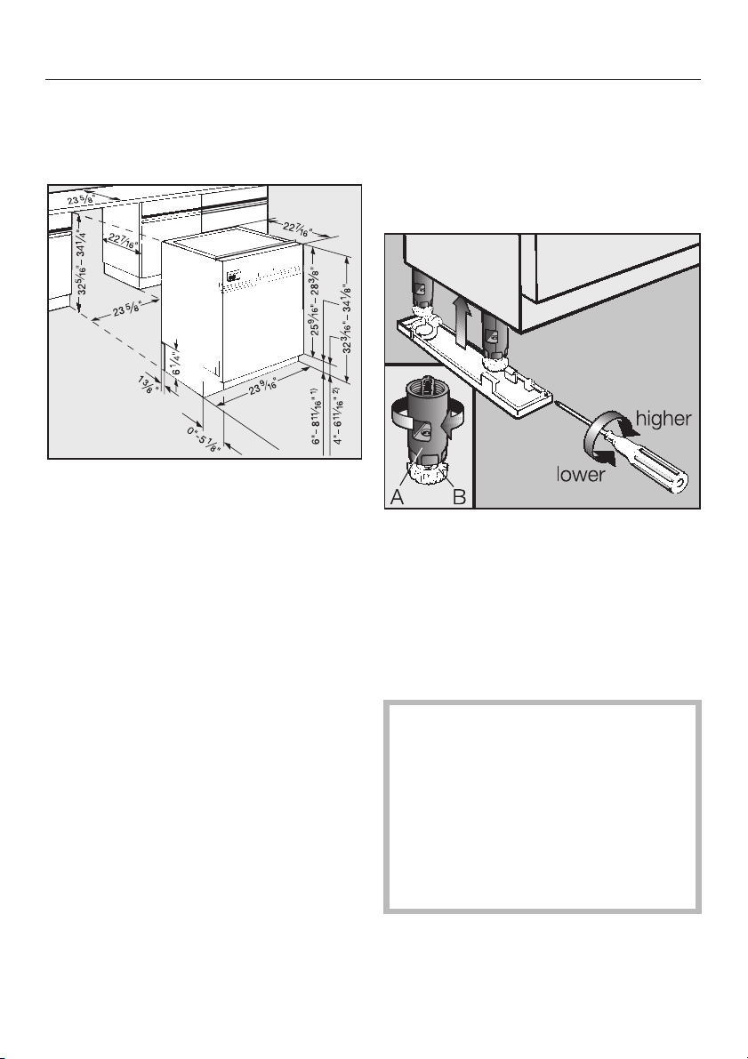
Product and Cut-out Dimensions
G 600 Series Dishwashers
Full size models G 636 - G 698
Removing the leg extensions
The black leg extensions can be
removed to reduce the height of the
machine to 32
1
/4" - 33" (819 - 838 mm)
(see Inset).
A = Black leg extension (removable)
B = White leg (must be installed on
machine).
^ After removing the black leg exten-
sions, screw the white legs onto the
dishwasher.
Machine heights of 331/4" - 34"
(845- 864 mm) are not possible
using the supplied legs.
For this height range, or for heights
greater than 34
7
/8" (886 mm),
extended legs (part # 02 702 601)
are necessary.
Contact the Miele Technical Service
Department for the appropriate legs.
8
Page 9
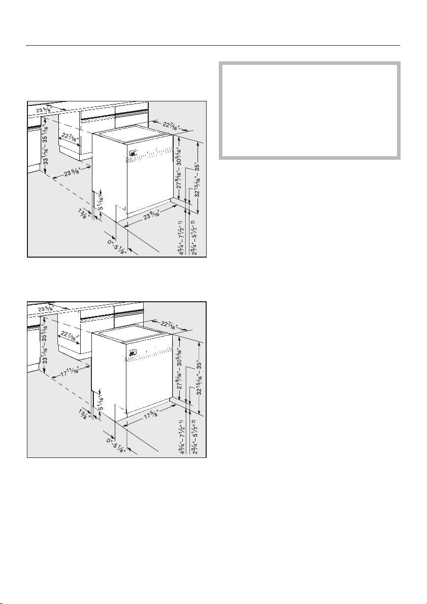
G 800 Series Dishwashers
Full size models G 836 - G 898
Slimline models G 801 - G 832
Product and Cut-out Dimensions
Machine heights of 35" - 37"
(889 - 940 mm) can be obtained if
the supplied legs are removed and
extended legs are attached.
Contact the Miele Technical Service
Department for the appropriate legs
(part # 02 702 601).
9
Page 10
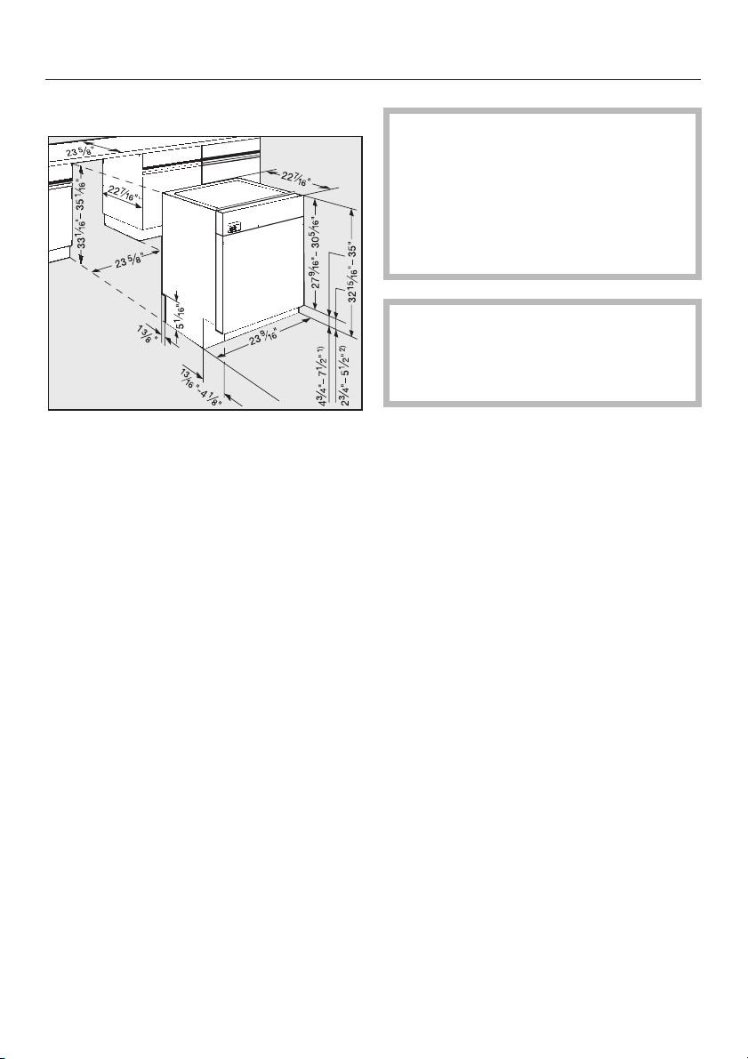
Product and Cut-out Dimensions
Prefinished models
Machine heights between 35" and
37" (889 - 940 mm) can be obtained
if the supplied legs are removed and
extended legs are attached. Please
contact the Miele Technical Service
Department for the appropriate legs
(part # 02 702 601).
,
washer should only be installed
under a continuous countertop and
securely fastened.
To ensure stability, this dish
-
10
Page 11

1.Install the steam deflector
Installation
A stainless steel steam deflector is sup
plied to protect the countertops from
steam and condesation when the dish
washer is opened. If the countertop is
made of Corian®, granite, marble or
other solid, waterproof material, the
steam deflector is not required.
If the counter is made of different
materials, the steam deflector
should be positioned so that it cov
ers the edge where the materials are
joined. Countertops with wood or
laminate edging should be tacked
through the rear holes of the steam
deflector.
-
-
-
Squeeze a bead of silicone sealant
^
from the supplied tube into the ridge
formed by the curved edge, a, of the
steam deflector.
^ Line up the steam deflector, b, with
the lower front edge of the countertop
and use the supplied tacks to secure.
^ Wipe off any excess silicone with a
rag.
The "Extended drying" feature can
be activated to further protect the
counter from condensation. See the
Operating instructions / Additional
features.
11
Page 12

Installation
2.Install the mounting brackets
To ensure stability, this dishwasher
should be securely attached to the
countertop with the two mounting
brackets included.
^ Insert the tab of each bracket into the
guide holes on the top of the dishwasher.
Stone or marble countertops:
Do not install these mounting brackets
if the counter is made of an extremely
hard material. The securing screws for
the mounting brackets are not suitable
for such materials.
3. Install the slide skis
Two slide skis are included and should
be installed on the feet of the dish
washer before the machine is pushed
under the countertop. This will allow the
machine to slide easier, protect the
floor, and allow adjustment of the rear
leveling legs from the front of the ma
chine.
First, adjust the height of the legs so
^
that the top of the dishwasher is
roughly
countertop.
Tipping the machine slightly to the rear,
if possible, will make adjusting the front
legs easier. Make sure the machine is
level when adjustments are complete.
1
/8" (3 mm) below the
-
-
12
^
Place the skis, with the ratchet at the
rear, under the dishwasher legs.
Page 13
4.Install the dishwasher
under the countertop
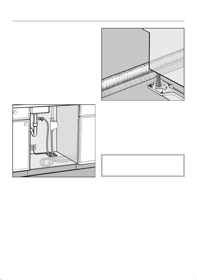
The dishwasher must be installed so
that the water and electricity supplies
can be accessed through an adjacent
cabinet. The supplies must not be lo
cated behind the machine.
Installation
-
The floor of the cut out where the dish
washer will be installed should be even
in height with the surrounding kitchen
floor. Plywood can be secured to the
floor to make the two areas even.
^
Make a 2" x 4" (5 x 10 cm) cut out in
the side or bottom of the cabinet ad
joining the dishwasher. This cut out is
necessary for connections to pass
through.
-
Slide the machine into the opening,
^
making sure the electrical cable and
hoses can reach their connection
points without kinking.
The drain hose connection at the rear of
the dishwasher can be turned to allow
the hose to be angled to the right or
left.
Exercise care when sliding the dishwasher in or out, to prevent damaging the power cord or hoses.
-
^
Make certain that there are no rough
edges that could damage the power
cord or hoses. If metal cabinets are
used, place the supplied rubber
grommet around the edge of the ope
ning before passing the cable
through.
-
13
Page 14

Installation
5. Level the legs
^ The rear leveling legs can be ad-
justed with a T20 Torx screwdriver by
turning the screws at the front of the
slide skis.
To raise the machine turn clockwise.
To lower the machine turn counter
clockwise.
Several turns may be needed to set the
correct height. Do not use a power
screwdriver.
^ Adjust the front leveling legs by
pushing on the feet with a slotted
screwdriver.
^ Tipping the machine slightly back-
wards, if possible will make adjusting
the front legs easier. Make sure the
machine is level when adjustments
are complete.
The dishwasher should be raised
until it just touches the underside of
the countertop.
If you are installing a prefinished unit
dishwasher proceed to step 9.
If you are installing a factory made
door panel (GDU Decor Set), refer to
the instruction manual enclosed with
the panel at this time.
14
Page 15

6. Install the control panel
Dishwashers with a selector knob
Installation
^ Press the "On/Off" button in and place
the cover, a, over the push button.
^ Insert the drying vent grill (if applica-
ble), b, into its opening.
^ Position the control panel, c, and
fasten it from the inside of the door,
d, using the six screws provided.
^ Align and press the knob onto its
shaft, e.
15
Page 16

Installation
Dishwashers with insertable push buttons
^ Press the "On/Off" button in and place
the cover, a, over the push button.
^ Insert the drying vent grill, b, into its
opening.
^ Position the control panel, c, and
fasten it from the inside of the door,
d, using the six screws provided.
^ Insert the other button covers, e and
f, into their openings.
16
Page 17

Dishwashers with fixed push buttons
Installation
^ Press the "On/Off" button in and place
the cover, a, over the push button.
^ Push the drying vent grill, b, into its
opening.
^ Position the control panel, c, and
fasten it from the inside of the door,
d, using the six screws provided.
17
Page 18
Installation
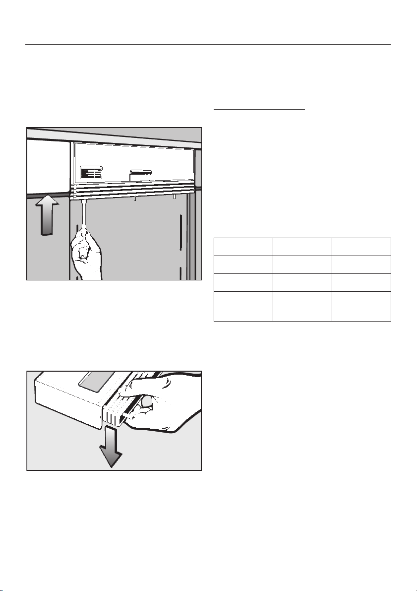
7. Align the control panel
The control panel should be aligned
with the drawer fronts of the adjoining
kitchen cabinets by adjusting the filler
strips.
^ Using an 8 mm socket, turn the nut
clockwise or counterclockwise until
the filler strips line up with the drawer
line.
If necessary, individual or all of the filler
strips can be removed.
After adjusting the control panel
^
height, cut off the plastic screw ex
cess.
Control Panel Height
41/2" control panel with(112 mm): out filler strips,
3
5
/4" control panel with
(145 mm): four filler strips,
6" using a fifth filler strip
(154 mm): (optional accessory).
Part numbers for additional filler
strips
Color Full size Slimline
white 4 047 341 4 312 770
black 4 047 361 4 312 780
Stainless
Steel
3 280 742
3 298 210
4 316 721
-
^
To remove the filler strips from the
control panel, place the panel printed
side up, and gently push down near
the bottom of the control panel. This
will release the mounting bolts from
their slots.
18
Page 19
Installation
8.Install the custom door
panel
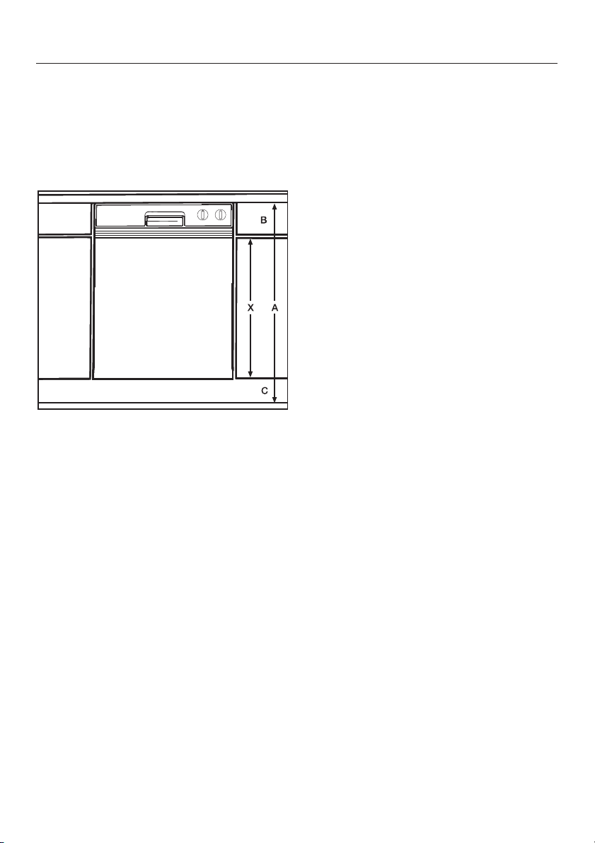
A custom door panel matching the
kitchen cabinetry can be installed using
the provided templates and bracket.
X = Panel length
A = Height to the underside of the
countertop
B = Control panel height*
C = Toe Kick Height
Length X:
Determined using the following calcula
tion: X = A – B – C
As long as the panel length calculated
is within the Range of Panel Sizes
listed, the custom panel should fit with
out a problem.
Range of Panel Sizes
G 636 - G 698
Length: 19" - 23
Width: 23
3
/4" (483 - 603 mm)
1
/2" (598 mm)
G 801 - G 832
Length: 21" - 25
Width: 17
3
/4" (533 - 654 mm)
1
/2" (445 mm)
G 836 - G 898
Length: 21" - 25
Width: 23
3
/4" (533 - 654 mm)
1
/2" (598 mm)
Note:
The maximum panel length is only applicable when no filler strips are
used. The door panel thickness should
3
be
/4" (19 mm).
Custom door panels should be finished
on all edges. Trim kits are not available
for custom door panels.
-
*Control panel height is determined by
the height of the drawers in the
cabinets. This height is adjustable
between 4
1
/2" and 53/4" (112 - 145 mm)
with the filler strips provided. An
additional filler strip and foam inserts
may be ordered to reach 6" (154 mm) in
height.
19
Page 20
Installation
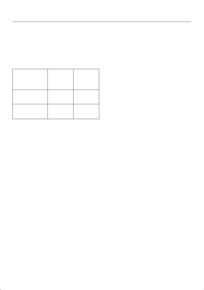
Maximum panel weight
A custom door panel must not exceed
the listed maximum weight. An over
weight panel will distort the door
springs causing the dishwasher door to
fall when opened.
-
Plastic control
panel
Stainless Steel
control panel
G 600
door
panel
13 lbs
(5.9 kg)
10.5 lbs
(4.8 kg)
G 800
door
panel
12 lbs
(5.5 kg)
9 lbs
(4.1 kg)
20
Page 21

Place a template on each end of the
^
mounting bracket as shown, making
sure the rule marks face the outside
of the bracket.
Installation
Slide the bracket up or down until the
^
oblong holes on the machine door
line up with the oblong holes on the
template (shown in inset a).
^ Draw a line on each template that is
even with the top edge of the adjacent cabinet door (inset b).
^
Hang the mounting bracket on the
machine door.
^
Slide the top edge of the templates
under the filler strips and control
panel.
^ Remove the bracket from the door.
^ Place the door panel on a flat sur-
face, good side facing down, taking
care not to scratch the surface. Make
certain that the bottom of the panel is
closest to you.
^
Place the bracket on the back of the
door panel and adjust it so that:
–
the lines drawn on the templates
align with the upper edge of the door
panel.
–
the mounting bracket is centered (left
to right) on the door panel.
21
Page 22

Installation
Tape the bracket to the door panel to
^
hold it in place while the mounting
holes are drilled.
^ Drill pilot holes for the screws using a
3
/32" (2.5 mm) bit.
^ Attach the bracket to the panel using
the 6 screws provided.
^ Remove the templates.
Save the templates for future use in
case a new door panel needs to be
installed.
22
Page 23

Attach the panel to the dishwasher
^
by aligning the bracket tabs with the
slots on the door.
Installation
Push up one side of the door panel
^
until it touches the filler strips (or con
trol panel if filler strips are not used)
and lightly tighten the T20 Torx
screws on the corresponding edge of
the machine door. Do not use a
power screwdriver.
Repeat the process with the other
^
side of the door panel.
Shut the door.
^
Check that the door panel is adjusted
^
correctly. It should be snug at the top
and neatly aligned with the cabinet
doors and drawer lines. If it is not
aligned properly, loosen the Torx
screws and adjust the panel.
Once the door panel is positioned correctly:
^ Open the dishwasher door.
^ Tighten all the Torx screws on the
edges of the dishwasher door.
-
^
Open the dishwasher door slightly. If
the locking screws on the edge of the
dishwasher door can not be reached,
the dishwasher will have to be pulled
out of its opening a few inches.
^ Use the provided caps to plug the
locking screw access holes.
23
Page 24

Installation
If the adjacent cabinetry (or appli
ance) does not have drawers and
alignment to a drawer line is not
possible:
^ Hang the bracket on the machine
door, without the templates. Tighten
the four locking screws on the edges
of the door panel.
^ Close the door.
^ Measure the distance from the adja-
cent cabinet’s (or appliance) door
bottom to the bottom of the mounting
bracket (X).
^
Draw a line on the rear of the door
panel (X) inches up from the bottom.
Remove the bracket from the ma
^
chine door and place it on the rear of
the door panel so that:
– the bracket is centered left to
right,
– the bottom of the bracket is
aligned with the (X) line.
^ Tape the bracket to the door panel to
hold it in place while the mounting
holes are drilled.
^
Drill pilot holes for the screws using a
3
/32" (2.5 mm) bit.
^
Attach the bracket to the panel using
the 6 screws provided.
24
Page 25
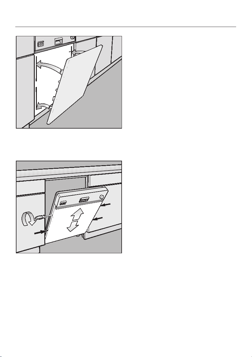
Attach the panel to the dishwasher
^
by lining up the bracket tabs with the
slots on the door.
Installation
Push up one side of the door panel
^
until it touches the filler strips (or con
trol panel if filler strips are not being
used) and lightly tighten the T20 Torx
screws on the corresponding edge of
the machine door. Do not use a
power screwdriver
Repeat the process with the other
^
side of the door panel.
Shut the door.
^
Check that the door panel is adjusted
^
correctly. It should be snug at the top
and neatly aligned with the adjacent
cabinetry. If it is not aligned properly,
loosen the Torx screws and readjust
the panel
Once the door panel is positioned correctly:
^ Open the dishwasher door.
^ Tighten all the Torx screws on the
edges of the dishwasher door.
-
^
Open the dishwasher door slightly. If
the locking screws on the edge of the
dishwasher door can not be reached,
the dishwasher will have to be pulled
out of its opening a few inches.
^ Use the provided caps to plug the
locking screw access holes.
25
Page 26
Installation
9.Secure the dishwasher
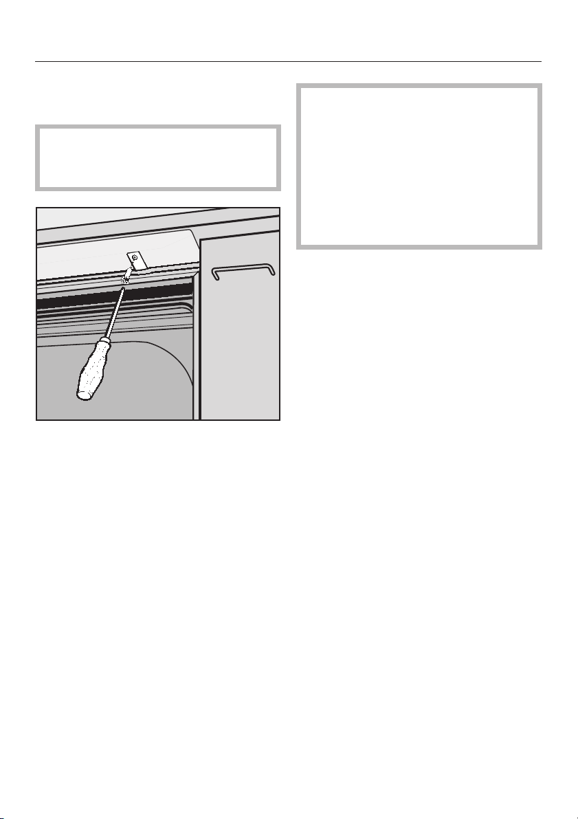
Open the dishwasher door.
^
If the steam deflector is installed, the
mounting bracket holes must align
with the slots in the steam deflector.
^ Using flat head screws, secure the
dishwasher to the countertop by
screwing through both the mounting
bracket and the steam deflector.
Make certain that the white rubber
seal located at the top, outer edge
of the dishwasher is tight against the
bottom of the countertop.
Do not drill any additional holes
through any part of the wash cabi
net. If in doubt on how to secure the
dishwasher, please call Miele’s Tech
nical Service Department.
-
-
26
Page 27

For openings exactly 173/4" (45 cm) or
5
23
/8" (60 cm) wide:
^ Open the dishwasher door and re-
move the caps covering the mounting holes on the outer edge of the
wash cabinet.
^ Fasten the dishwasher to the adja-
cent cabinets using the supplied
screws and bushings. A bushing
must
be placed over the screw be-
fore inserting it into its mounting hole.
Installation
The side mounting holes
,
should only be used for securing
the dishwasher if the opening is
exactly 17
line models) or 23
wide (full size models).
Use of this method on larger
openings can damage the ma
chine and cause leaks. Be careful
not to screw into an adjacent ap
pliance.
3
/4" (45 cm) wide (slim
5
/8" (60 cm)
-
-
^
Tighten the screws and insert the
caps.
27
Page 28

Installation
10. Adjust the door springs
Open the dishwasher door halfway.
^
If the door remains in this position when
released, the springs are adjusted cor
rectly.
If the door drops, the tension on the
springs needs to be increased.
If it closes on its own, the tension on the
springs need to be decreased.
-
Note:
If the door springs can not be adjusted
enough (the door falls), the custom
door panel is too heavy.
Call your Miele dealer or Miele’s Techni
cal Service Department for advice on
stronger door spings.
-
^
To adjust the door springs use a T20
Torx or a small slotted screwdriver
and turn the screw located behind
the door in the upper front strip, on
the left hand side of the dishwasher.
Do not use a power screwdriver.
– turn clockwise to increase the
tension
– turn counterclockwise to de-
crease the tension.
28
Page 29
Installation
11. Make the plumbing
connections
An air gap is built into the water inlet
system to prevent potable water from
mixing with waste water.
The dishwasher can heat its own water
to the temperatures required by the
wash program. This allows the option of
connecting the machine to either a hot
or cold water source.
For lowest energy consumption con
^
nect the dishwasher to a cold water
source.
^ For fastest possible wash times, with
slightly higher energy consumption,
connect the dishwasher to a hot
water source.
Hot water supply specifications:
Recommended temperature:
120 °F (49 °C), max 140 °F (60 °C)
New plumbing:
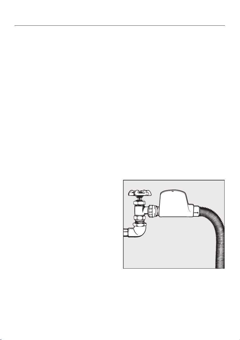
The water inlet hose comes equipped
3
with a
tor. This can be directly connected to a
shut off valve with
thread ends).
Preferred Installation:
The hose assembly should be installed
vertically so the hose exits from the bot
tom of the valve box (not as shown).
-
If this is not possible, it can be installed
horizontally, provided the hose exit re
mains beneath the main body of the
valve box (see illustration). The valve
box should also be installed so that it is
at least 10" (24 cm) above the floor (or
base of the cabinet), so that the excess
coiled hose will remain lower than the
valve box at all points.
/4" female hose thread connec
3
/4" MHT (male hose
-
-
-
Water pressure:
Must be between 5 - 145 psi
(0.3 -10 bar).
If the water pressure is too low, the "In
take/Drain" or "Intake" indicator may
flash (see Operating Instructions/ "Fre
quently asked questions").
If the water pressure is too high, a pres
sure reducer must be installed.
-
-
-
29
Page 30

Installation
Existing plumbing:
If the standard
a dishwasher already exists with a com
pression fitting and valve as pictured:
^ Cut the
valve.
^ Install the
MHT (Male Hose Thread) adapter
(supplied with the machine), as illustrated.
^
For any other size plumbing, pur
chase the correct size adapter from a
hardware store.
3
/8" copper plumbing for
3
/8" copper tubing after the
3
/8" compression to3/4"
-
-
Do not cut the intake hose. If the
,
hose is cut, the dishwasher will not
work. There will be a water leak and
you could be injured. If the hose is
too long, coil it neatly and place it
behind the machine.
Electrical wiring and components
should not come into contact with
any plumbing fixtures or hoses.
^
Connect the inlet hose to the existing
valve/adapter assembly.
30
Page 31

Drainage system specifications:
The machine comes equipped with:
A 5 ft. long (1.5 m) flexible drain hose
–
with an internal diameter of
7
/8"
(22 mm). Drain hose extensions can
be ordered from Miele’s Technical
Service Department.
A built-in swivel connector allowing
–
the drain hose to be routed in any
direction.
A built-in mechanical non-return
–
valve on the discharge side to pre
vent waste water from flowing back
into the dishwasher.
– A built-in odor trap on the discharge
side to prevent odors from entering
the kitchen.
Maximum drain height: 39" (1 m)
Installation
Connect the supplied drain hose to the
drain pipe of the kitchen sink either:
– above the P trap using the clamp
provided, or
– to the dishwasher connector of the
garbage disposal.
Maximum drain hose length: 12 ft
(3.5 m)
Do not shorten the drain hose.
Do not connect the drain hose to
anything but a genuine Miele hose.
Other hoses may melt or collapse.
When connecting the drain hose to
the garbage disposal, make sure to
remove the knockout from the connection nipple. (See the disposal
manufacturer’s instructions for this
procedure.)
31
Page 32

Installation
Venting the drainage system
If the dishwasher drain hose is con
-
nected to a floor drain or to a drain
pipe that is less than 8" (20 cm)
above the floor, the drain must be
vented. Otherwise the water inside the
dishwasher may siphon out during the
wash program.
To vent the drain:
Open the dishwasher door and
^
remove the lower basket.
Additional note
Since all Miele dishwashers are
equipped with an odor trap and nonreturn valve, the drain hose can be
connected directly to the drain pipe as
illustrated.
If plumbing codes require an external
air gap on the discharge side of the
dishwasher, the following requirements
must be met:
No part of the drain hose should be
–
higher than 39" (1 m).
If installed horizontally, the drain
–
hose can be up to 12 ft (3.5 m) long.
If the drain hose is angled upwards
in any way, it cannot be longer than
5 ft (1.5 m).
– The drain connection should be
made as close as possible to the
dishwasher.
– The internal diameter (
7
/8" or 22 mm)
of the drain hose should not be
reduced at any point.
^
Cut off the vent cap located at the
right rear of the triple filter system, as
illustrated.
32
Page 33
Installation
12. Make the electrical
connection
GROUNDING INSTRUCTIONS
THIS APPLIANCE MUST BE
GROUNDED.
In the event of a malfunction or break
down, grounding will reduce the risk of
electric shock by providing a path of
least resistance for the electrical cur
rent. This appliance is equipped with a
cord having an equipment grounding
conductor and a grounding plug. The
plug must be plugged into an appropriate outlet that is installed and grounded
in accordance with all local codes and
ordinances.
,
Improper connection of the
equipment grounding conductor
can result in electric shock. Do
not modify the plug provided with
the appliance; if it will not fit the
outlet, have a proper outlet in
stalled by a qualified electrician. If
there is any question concerning
the proper electrical connection or
grounding of this appliance to the
power supply, please consult a li
censed electrician or call Miele’s
Technical Service Department:
-
-
-
-
Specifications
The dishwasher comes equipped with a
4 ft (1.2 m) power cord with a molded
plug for connection to 120 V, 60 Hz,
15 A grounded receptacle.
Rated load:. . . . . . . . . . 12.5 A / 1500 W
Voltage: . . . . . . . . . . . . . . . . . . 120 VAC
Frequency: . . . . . . . . . . . . . . . . . . 60 Hz
Circuit breaker:. . . . . . . . . . . . . . . . 15 A
USA 1-800-999-1360
CDN 1-800-565-6435
33
Page 34

Installation
Power outlet
The power outlet for the appliance must
be installed within a cabinet, on a wall
adjacent to the undercounter space in
which the dishwasher is located. An o
pening through the partition between
the compartments of 1
can be made to allow the plug to pass
through.
1
/2" (3 to 4 cm)
-
Permanent Connection (Hard Wiring)
For hard wiring, the power cord must
be disconnected from the terminal box
located at the lower left front of the
dishwasher, behind the toekick and ser
vice panel. Pass the permanent power
supply cable through the strain relief
and secure it to the terminal box.
Connect:
L1 (Black) to L on terminal block
N (White) to N on terminal block
GRND to ground connector
GROUNDING INSTRUCTIONS
This appliance must be connected
to a grounded metal, permanent wiring system, or an equipment
grounding conductor must be run
with the circuit conductors and connected to the equipment grounding
terminal or lead on the appliance.
-
34
Use copper conductors only.
,
Hardwiring the dishwasher
should only be done if required by
local electrical codes, and then in
accordance with those codes. Do
not cut the plug off the power sup
ply cord and connect it directly to
the house wiring.
-
Page 35

Installation
13. Test the unit
Once the dishwasher is level and se
cured it should be tested.
Remove all packing and literature
^
from inside the unit.
The yellow Child Safety Lock key
hung on the upper basket must
removed before operating the dish
washer. If not removed, the key
could become lodged in the circula
tion pump.
be
Check for any leaks, odd noises and
^
-
-
-
flashing / lit fault indicators on the
control panel. See the "Operating In
structions / Frequently asked ques
tions" if there is a problem.
-
-
^
Make sure the triple filter system in
the base of the wash cabinet is
locked in place. Turn the handle
clockwise to lock.
^
Close the soap dispenser. Do not
add detergent.
^
Run the dishwasher through the
"Rinse & Hold" program. See the op
erating instructions for information on
operation and program selection.
-
35
Page 36
Installation
14. Install the toekick
For installations using a continuous
toekick or a cabinet matching toekick
Before installing the toekick
ments must be taken to ensure that the
toekick will not interfere with the com
plete opening of the dishwasher door.
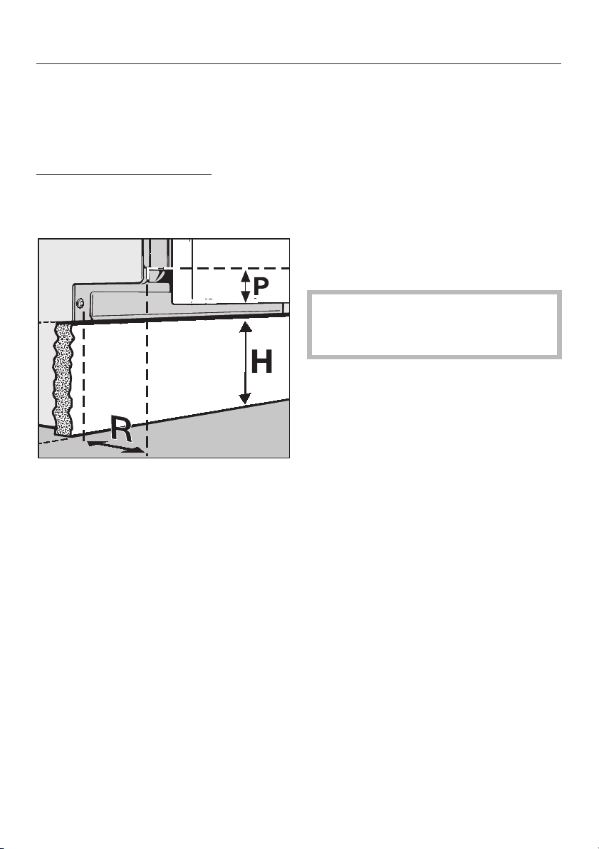
The door panel overhang (P), and
toekick depth of recess (R), determine
the maximum dishwasher toekick
height (H).
, measure
-
-
If the door panel hits the toekick when
the dishwasher door is opened, the
toekick must be cut shorter or recessed
deeper.
Note:
If a decorative or flush mount toekick is
desired, and (R) is less than
3
/4"
(19 mm), other modifications, such as
beveling the top rear edge of the
toekick, may be necessary.
It is extremely important that the
toekick is removable in case service
is needed.
If (H) is equal to or less than the toekick
height of the adjoining cabinets, no
interference will exist, provided that (R)
is at least
36
3
/4" (19 mm).
Page 37
For installations using the included
plastic toekick
Installation
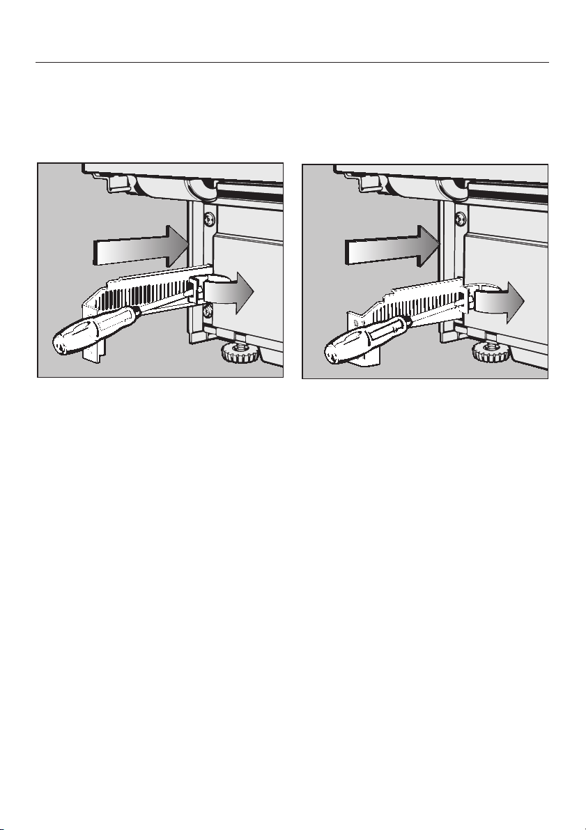
G 600 Series dishwasher
^ Insert the mounting bracket with the
flange pointing toward the center of
the machine.
^ Push the mounting brackets in as far
as possible by releasing the tension
on the spring clip (see illustration).
G 800 Series dishwasher and
"U" model
^ Insert the mounting bracket with the
flange pointing toward the outside of
the machine.
^ Push the mounting brackets in as far
as possible by releasing the tension
on the spring clip (see illustration).
37
Page 38
Installation
The included toekick will fit without
modification if the machine is set to its
maximum height and the toekick is re
cessed as far as possible (4" / 10 cm).
-
If the machine height is less than maxi
mum, or if the toekick is not recessed 4"
(10 cm), the toekick must be shortened.
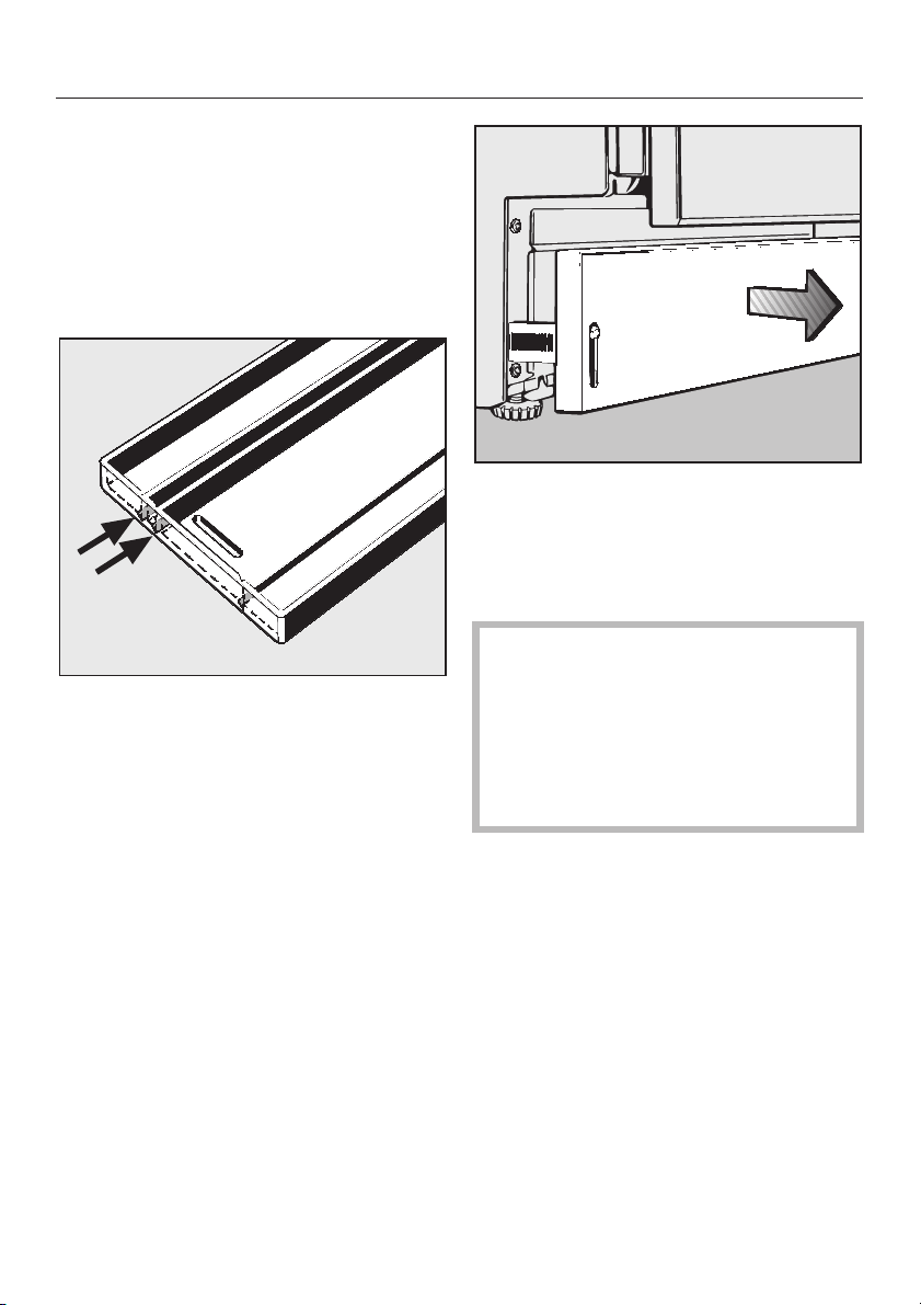
The rear of the toekick has two cutting
lines.
-
Screw the toekick onto the installed
^
brackets, with the cutting lines towards the top, and pull out evenly
and slowly until it aligns with the
toekick of the adjoining cabinets.
The toekick can not be pushed
back in once it has been extended.
It must be unscrewed, so that the
tension on the spring clips can be
released. The brackets can then
be pushed in, and the toekick reat
tached.
-
38
Page 39
Installation
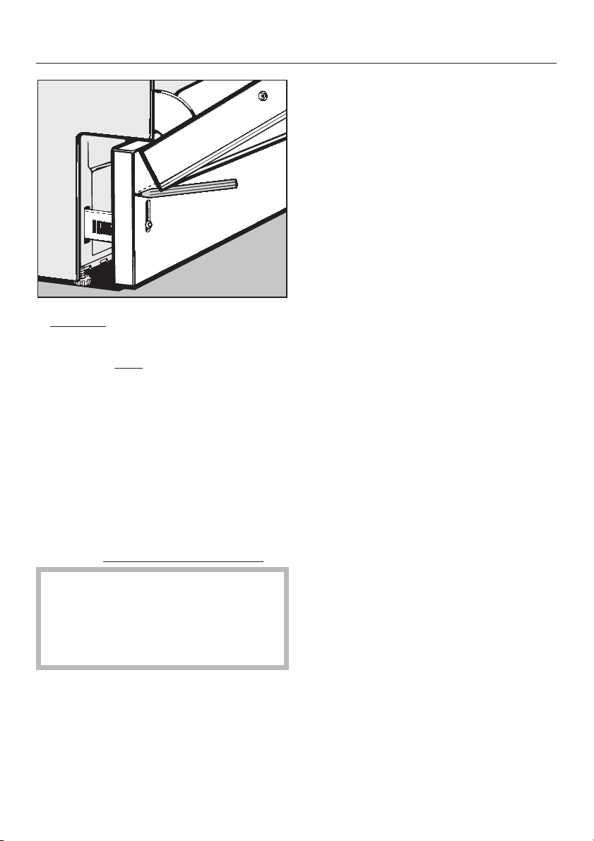
Carefully
^
until it hits the toekick.
^ Using the front
door panel as a guide, draw a line
across the toekick.
^ Unscrew and remove the toekick.
^ If one of the cutting lines is close to
the line just drawn, score the front of
the toekick, and snap off the excess,
otherwise, trim the toekick along the
line using a saw.
^
Screw the toekick back onto the brack
ets, with the cut edge at the bottom
,
the dishwasher door to check that
the front panel does not hit the
toekick. If it does, remove the
toekick and trim it accordingly.
open the dishwasher door
lower edge of the
After installation, carefully open
-
.
39
Page 40

Alteration rights reserved (NovoplusB,P,S) / 2702
This bio-friendly paper was bleached without the use of chlorine.
M.-Nr. 05 690 921 / V
00
 Loading...