

Page 1
Installation instructions
for dishwashers
It is essential to read the operating and
installation instructions before
installing or using the machine,
to avoid the risk of accident or
damage to the machine. M.-Nr. 05 223 031
@ä
Page 2

These installation instructions apply to several different dishwasher models.
Model numbers in this booklet refer to the model designation specified on the
data plate on the machine (and not the description on the control panel). The
data plate is located at the top of the door when open.
The model numbers quoted refer only to the basic model number, e.g. the
G 640 SCi is described as the G 640 in this booklet.
It is essential to read the Warning and Safety Instructions in the Operating
Instruction booklet before installing the dishwasher.
2
Page 3

Contents
Contents
Installing a freestanding dishwasher. . . . . . . . . . . . . . . . . . . . . . . . . . . . . . . . . . 4
Decor frame and decor panel . . . . . . . . . . . . . . . . . . . . . . . . . . . . . . . . . . . . . . . . . 4
Installing integrated “i” Dishwashers . . . . . . . . . . . . . . . . . . . . . . . . . . . . . . . . . 5
1. Fit worktop protection . . . . . . . . . . . . . . . . . . . . . . . . . . . . . . . . . . . . . . . . . . . . . 7
2. Building the dishwasher into a niche . . . . . . . . . . . . . . . . . . . . . . . . . . . . . . . . . . 7
Slides . . . . . . . . . . . . . . . . . . . . . . . . . . . . . . . . . . . . . . . . . . . . . . . . . . . . . . . . . 8
Securing pieces . . . . . . . . . . . . . . . . . . . . . . . . . . . . . . . . . . . . . . . . . . . . . . . . . 8
Screw feet . . . . . . . . . . . . . . . . . . . . . . . . . . . . . . . . . . . . . . . . . . . . . . . . . . . . . . 9
3. Fitting the facia panel. . . . . . . . . . . . . . . . . . . . . . . . . . . . . . . . . . . . . . . . . . . . . 10
4. Matching the facia panel to the dimensions of the adjacent drawer fronts. . . . 12
5. Fitting the (matching) door front. . . . . . . . . . . . . . . . . . . . . . . . . . . . . . . . . . . . . 13
6. Securing the dishwasher . . . . . . . . . . . . . . . . . . . . . . . . . . . . . . . . . . . . . . . . . . 16
7. Adjusting the door springs. . . . . . . . . . . . . . . . . . . . . . . . . . . . . . . . . . . . . . . . . 16
8. Matching the plinth facia of a kitchen run . . . . . . . . . . . . . . . . . . . . . . . . . . . . . 17
For kitchens utilizing a non-continuous plinth facia . . . . . . . . . . . . . . . . . . . . . 18
Electrical connection . . . . . . . . . . . . . . . . . . . . . . . . . . . . . . . . . . . . . . . . . . . . . . 20
Plumbing. . . . . . . . . . . . . . . . . . . . . . . . . . . . . . . . . . . . . . . . . . . . . . . . . . . . . . . . 22
Connection to the water inlet . . . . . . . . . . . . . . . . . . . . . . . . . . . . . . . . . . . . . . . . . 22
Drainage . . . . . . . . . . . . . . . . . . . . . . . . . . . . . . . . . . . . . . . . . . . . . . . . . . . . . . . . 24
Venting the drainage system . . . . . . . . . . . . . . . . . . . . . . . . . . . . . . . . . . . . . . 24
Special accessories . . . . . . . . . . . . . . . . . . . . . . . . . . . . . . . . . . . . . . . . . . . . . . . 25
“i”- (integrated) Dishwashers . . . . . . . . . . . . . . . . . . . . . . . . . . . . . . . . . . . . . . . . . 25
Freestanding dishwashers. . . . . . . . . . . . . . . . . . . . . . . . . . . . . . . . . . . . . . . . . . . 25
Technical data . . . . . . . . . . . . . . . . . . . . . . . . . . . . . . . . . . . . . . . . . . . . . . . . . . . 26
3
Page 4
Installing a freestanding dishwasher
Installing a freestanding dishwasher
Freestanding dishwashers
Freestanding dishwashers do not require any special installation fixings in
the kitchen, (except for plumbing).
The dishwasher must be level and
stable when installed.
Any unevenness in the floor level
can be compensated for by adjusting the four screw feet.
The adjustment range is approx. 1 cm
(85 - 86 cm total height).
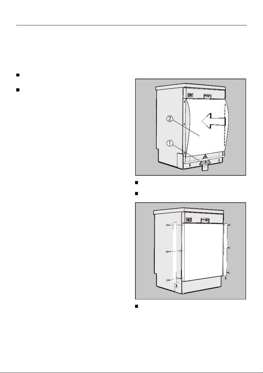
Decor frame and decor panel
A decor frame can be added to take a
panel for matching the dishwasher to
the kitchen fronts.
With some models this is fitted as
standard. Otherwise a decor frame can
be ordered as an extra accessory.
Dimensions for decor panels up to 1
mm thick:
Models:
G 601 - G 624
G 801 - G 824
G 640 - G 691
G 840 - G 891
437 x 603 x 1 mm
}
587 x 603 x 1 mm
}
With decor panels 1 to 4 mm thick, an
extra decor frame adapter strip (special accessory) must be fitted to the
control facia panel.
Screw on the lower deco strip b .
Insert the decor panel c .
Dimensions for decor panels between 1
and 4 mm thick:
Models:
G 601 - G 624
G 801 - G 824
G 640 - G 691
G 840 - G 891
4
437 x 599 x 1 - 4 mm
}
587 x 599 x 1 - 4 mm
}
Screw the side decor strips into
position.
Page 5

Installing integrated “i” Dishwashers
Installing integrated “i” Dishwashers
Integrated (“i”) dishwashers
“i” dishwashers are specially designed
for building under a continuous worktop.
– The control panel with its acces-
sories is included with the “i” dishwasher in a separate package for onsite fixing.
– The front is designed to be fitted with
a base unit “door” front to match the
kitchen furniture.
– The dishwasher does not have a
plinth facia. The plinth area can be
covered either with facia to match
your kitchen furniture if available, or
another facia. The separate plinth
facia can be fitted to match the
height of adjacent plinths. The plinth
return is freely adjustable.
All notes on installation are described
in the following section.
The “i” model dishwasheres can be
coverted into a built-under “U” dishwasher.
– A decor set GDU must be used.
– A plinth facia to cover the plinth area
is supplied with the decor set. The
plinth facia can be fitted to match
the height of adjacent plinths. The
plinth return is freely adjustable.
The decor set is supplied with a
separate installation booklet.
To ensure stability, “i” and “U”
model dishwashers must only be installed under a continuous worktop
which must be securely screwed to
neighbouring units.
The dishwasher must not be installed under a hob. The high
radiant temperatures which are
sometimes generated by a hob
could damage the dishwasher.
5
Page 6
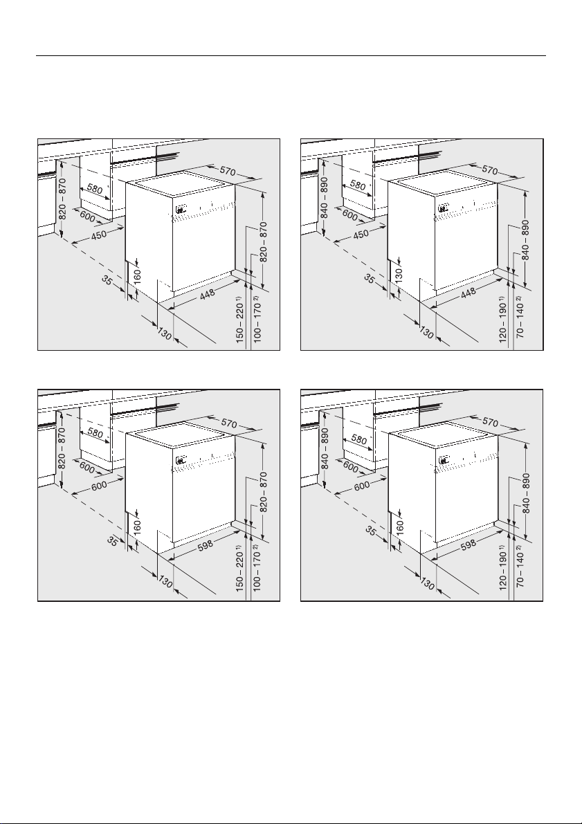
Installing integrated “i” Dishwashers
Building in dimensions
Dishwasher models G 601 - G 624
Dishwasher models G 640 - G 691
Dishwasher models G 801 - G 824
Dishwasher models G 840 - G 891
1) with 870 mm machine height
2) with 820 mm machine height
Range of adjustment approx. 5 cm (82 87 cm total height).
Extended machine feet are available at
extra cost, (special accessory) where a
machine height of 87 to 92 cm is required.
6
1) with 890 mm machine height
2) with 840 mm machine height
Range of adjustment approx. 5 cm (84 89 cm total height).
Extended machine feet are available at
extra cost, (special accessory) where a
machine height of 89 to 94 cm is required.
Page 7
Installing integrated “i” Dishwashers
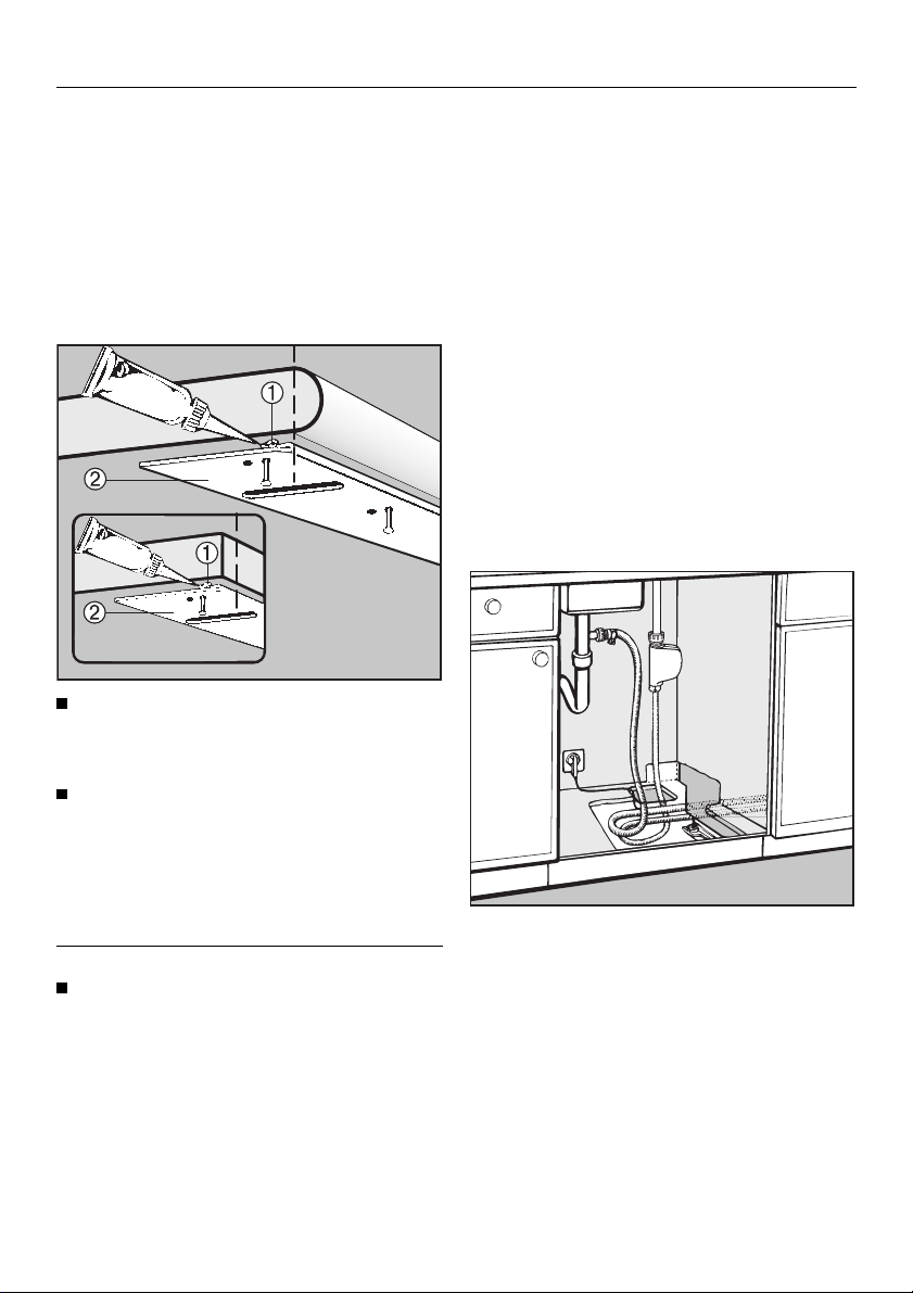
1.Fit worktop protection
A stainless steel “niro” cover plate is
supplied with the machine to protect
the underside of the worktop against
steam rising from the machine.
The cover plate is supplied as standard with “i” models.
Squeeze sealant from the tube supplied
b into the angle of the “niro”
plate.
2.Building the dishwasher
into a niche
Connection to water and drainage
should be sited beside and not behind
the dishwasher for accessibility. Connections are usually made in the area
under the sink. Many kitchen unit manufacturers provide a cutout in the base
of the sink base unit for the hoses to be
fed through.
If the base unit has no opening and if
there is not an opening through the
plinth area for connections, one must
be cut.
Suggested dimensions: 60 x 110 mm.
Align the “niro” plate c to the front
edge of the worktop - see illustration and then use the tacks supplied to
nail the “niro” plate to the underside
of the worktop.
Worktops with wood or laminate edging:
Nail the tacks through the holes
further back from the edge.
7
Page 8
Installing integrated “i” Dishwashers
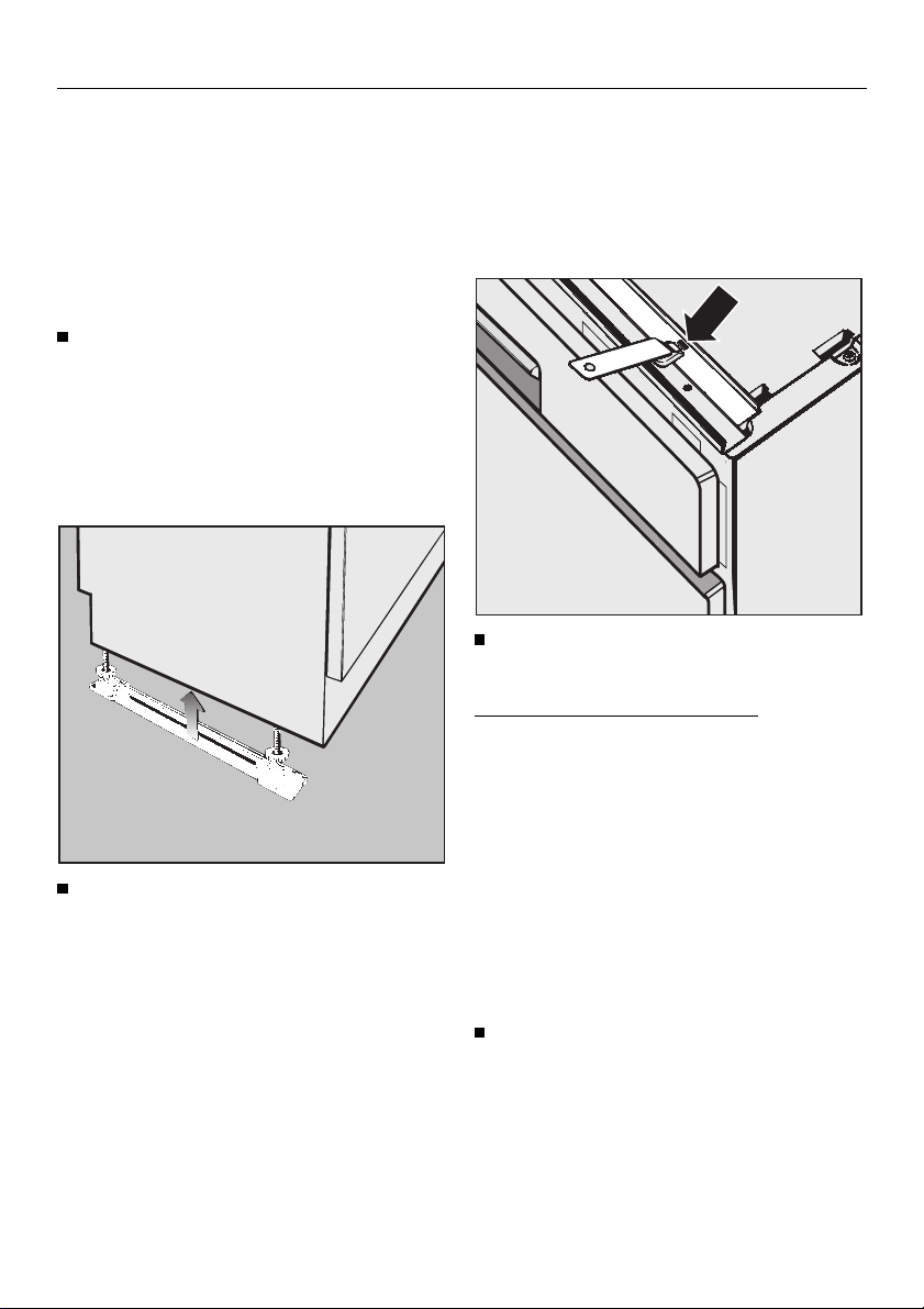
Slides
The slides make installation of the dishwasher easier and protect the floor
from possible damage when moving
the appliance into and out of the recess. They are also used for adjusting
the height of the rear screw feet.
Adjust the height manually before installing the dishwasher.
Leave a space of approx. 5 mm below
the worktop to allow the dishwasher
to be pushed back easily into the recess. Make sure that the dishwasher
stands level.
Press the slides - with the ratchet at
the rear - under the screw feet.
Securing pieces
To ensure stability, the dishwasher must
be fixed securely to the worktop (step 6).
Two securing pieces are supplied for
this purpose.
Fit the securing pieces into the slots
on both the left and right hand sides.
Granite and marble worktops:
With these worktops the dishwasher
must be securely screwed to neighbouring units on the right and left hand
sides. For this you will require two special fixing brackets (available as a special accessory at extra cost).
The angle support for the water drainage hose at the rear of the dishwasher
can be turned.
Turn the angle support in the direction of the on-site connection for the
drainage hose.
8
Page 9
Installing integrated “i” Dishwashers
Push the dishwasher right back into
the recess. Ensure that the drain
hose, inlet hose and the electric
cable are laid to reach the connection point without any kinks.
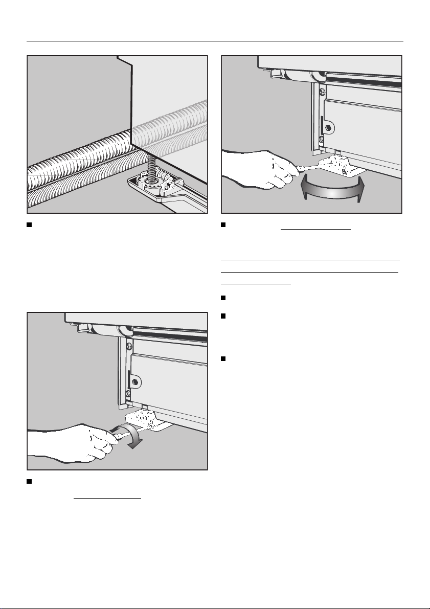
Screw feet
Use a TORX T20 screwdriver to adjust the
quired height.
rear screw feet to the re-
Adjust the front screw feet manually
or with a flat blade screwdriver.
It is easier to adjust the screw feet if the
weight of the dishwasher is not bearing
down on them.
If possible tip the machine slightly.
For fine adjustments it may be
necessary to press with a screwdriver against the cogs of the feet.
Screw the feet out until the dishwasher is right up against the underside of the worktop, to which it will
be screwed later. Ensure that the
dishwasher stands level.
Higher = turn clockwise
Lower = turn anti-clockwise
Several turns are needed to adjust 1 mm
in height.
9
Page 10

Installing integrated “i” Dishwashers
3. Fitting the facia panel
Dishwashers with selector dial, without drying fan
(G 601 - G 604, G 640 - G 644, G 801 - G 804, G 840 - G 844)
Attach cap b to the push button
switch.
Place the facia panel c in position
and use the six screws
in place through from the inside of
the door.
d to screw
Attach selector e .
10
Page 11

Installing integrated “i” Dishwashers
Dishwashers with selector dial and drying fan
(G 611 - G 624, G 646 - G 686, G 811 - G 824, G 846 - G 884)
Attach cap b to push button switch.
Push the ventillation grille c into po-
sition so that the slats on the grille
are facing downwards.
Dishwashers with programme selector buttons and drying fan
(G 691, G 891)
Attach cap b to push button switch.
Push the ventillation grille c into po-
sition so that the slats on the grille
are facing downwards.
Place the facia panel d in position
and use the six screws
in place through from the inside of
the door.
Attach selector f.
Place the facia panel d in position
and use the six screws
in place through from the inside of
the door.
e to screw
e to screw
11
Page 12

Installing integrated “i” Dishwashers
4.Matching the facia panel to
the dimensions of the
adjacent drawer fronts
The facia panel can be aligned with the
drawer fronts by adjusting the spacer
bars.
Using an 8 mm socket spanner turn
clockwise or anti-clockwise until the
required height is reached.
Adjustment range:
from 112 mm: facia panel without
spacer bars
to 145 mm: facia panel with
up to 4 spacer bars
to 154 mm: using a fifth spacer bar
(special accessory at
at extra cost)
Please note
After adjustment cut off any protruding
lengths of screws.
If necessary some or all spacer bars
can be removed.
Press out the spacer bars from the fitting slits in the facia panel.
12
Page 13

Installing integrated “i” Dishwashers
5.Fitting the (matching) door
front
The door of the kitchen base unit (without the drawer facia or fittings) is normally used for the door front.
The door front is fixed to the machine
door outer panel using a fixing bracket
which has to be pre-mounted on the
rear of the door front.
Templates are provided to position the
fixing bracket and the door front accurately.
Fixing brackets are already fitted on
stainless steel door fronts. These fronts
cannot be shortened.
Door fronts differ in weight and it is
therefore essential that the door
springs are adjusted (see Step 7)
after the door front has been fitted.
On each side of the fixing bracket
position a template with the rule
markings facing outwards.
Hang the fixing bracket into the slits
in the machine door outer panel.
Push the overhanging ends of the
templates under the facia panel.
13
Page 14

Installing integrated “i” Dishwashers
Adjust the fixing bracket D:
The long holes in the machine door
outer panel must be aligned with the
matching markings on the template.
Mark the height of the top edge of
adjacent kitchen base unit doors on
the template
Take off the fixing bracket.
Lay the door front down with the rear
side facing upwards.
E .
Lay the bracket on the rear side of
the door front and adjust so that:
– the marks on the template for the
upper edge of the adjacent base
unit doors match the top edge of the
door front.
– The fixing bracket must be the same
distance from the left and right hand
side edges of the door front.
Use strips of adhesive tape to hold
the bracket in this position.
14
Page 15

Installing integrated “i” Dishwashers
Drill the fixing holes to a depth of
about 10 mm, using a 2.5 mm drill
bit.
Secure the fixing bracket to the door
front using the flat-head screws supplied.
Take off the templates.
Keep the templates in case the dishwasher is ever fitted with a new door
front.
Open the dishwasher door slightly.
Adjust the door front for the height
on one side and lightly screw in a
T20 Torx screw on this side.
Adjust the door front height on the
other side and also lightly screw in a
T20 Torx screw on this side.
Shut the dishwasher door.
Check the door front for correct align-
ment.
If necessary unscrew and re-adjust.
Once the door front is correctly positioned:
Open the dishwasher door.
Tighten all the Torx screws on the
sides.
Plug the openings for the fixing
screws using the plastic stoppers
provided.
Hang the foor front into the slits in
the machine door outer panel.
15
Page 16

Installing integrated “i” Dishwashers
6. Securing the dishwasher
Open the dishwasher door.
The holes in the securing pieces
must line up with the long holes in
the “niro” steel cover plate. If this is
not the case, adjust the position of
the dishwasher in the niche (ensure
that the dishwasher is the same distance from the neighbouring kitchen
units on the right and left hand
sides and line the dishwasher door
front up with neighbouring door
fronts).
7.Adjusting the door springs
The door springs are correctly adjusted
when the door remains stationary when
left open at 45 °.
If the door drops down, then the door
springs need to be tightened.
If it closes then the springs need to be
released.
The adjusting screw is located in the
upper front strip at the left hand side of
the dishwasher.
Half open the dishwasher door.
Screw the countersunk screws
(3.9 x 22) supplied upwards through
the securing pieces on the left and
right hand sides into the work surface to secure the dishwasher.
Ensure that the seal on the top
edge of the dishwasher fits directly
against the worktop. If this is not the
case, adjust the height adjustable
feet some more, (see Step 2).
16
The door springs are easier to adjust
when the door is only half open than
when it is fully open.
Adjust the door spring with a Torx
T20 or a 1 x 5.5 mm screwdriver until
it is correctly balanced:
– turn clockwise = tighten
– turn anti-clockwise = loosen.
Page 17

Installing integrated “i” Dishwashers
8.Matching the plinth facia
of a kitchen run
The plinth area of the dishwasher is normally covered with a plinth run matching the kitchen furniture.
The height (H) of the plinth facia around
the dishwasher depends on the plinth return (R) and how much the door front extends below the dishwasher door (P).
Place the plinth facia directly in front
of the kitchen run but do not attach.
Carefully open the dishwasher door.
If the door front comes into contact with
the kitchen plinth when the dishwasher
door is opened the plinth facia in the
area around the dishwasher door
needs to be cut to size.
To do this mark where the edge of
the door front comes into contact
with the plinth facia.
Cut the plinth facia to size along this
line.
Place the plinth facia in front of the
kitchen run again and check whether
the dishwasher door can be opened
fully.
If it cannot, trim the plinth facia to the
correct size.
Secure the plinth facia to the adjacent kitchen units.
If your kitchen does not have a plinth
run matching the kitchen furniture, the
plinth area can be covered with a separate plinth kit.
17
Page 18

Installing integrated “i” Dishwashers
For kitchens utilizing a non-continuous plinth facia
The included plinth facia will fit without
modification when:
– The machine is set to its maximum
height (legs fully extended), and
– the toekick is recessed as far as
possible (100 mm).
If the machine height is less than maximum, or if the plinth facia is recessed
less than 100 mm, the plinth facia must
be shortened (see following page).
After installation, carefully open the
dishwasher door to check that the
front panel does not hit the plinth
facia. If it does, remove the toekick
and trim it accordingly.
Adjusting the plinth facia recess
To adjust the depth (recess) of the
plinth facia, release the tension on the
spring clips as shown, and push the
mounting brackets in as far as
possible.
Dishwasher model G 6XX
(see data plate for model number)
The flange on the end of the mounting
brackets must point towards the center
of the machine.
Dishwasher model G 8XX
(see data plate for model number)
18
The flange on the end of the mounting
brackets must point towards the outside of the machine.
Page 19

Installing integrated “i” Dishwashers
Trimming the plinth facia
The rear of the plinth facia has two cutting lines.
Carefully open the dishwasher door
until it hits the plinth facia.
Using the front lower edge of the
door panel as a guide, draw a line
across the plinth facia.
Unscrew and remove the plinth facia.
If one of the cutting lines is close to
the line just drawn, score the front of
the plinth facia, and snap off the excess. Otherwise trim the plinth facia
along the line using a saw.
Screw the plinth facia onto the installed brackets, with the cutting
lines towards the top, and pull out
evenly until it aligns with the plinth
facia of the adjoining cabinets.
The plinth facia cannot be pushed back
in. It must be unscrewed, so that the tension on the spring clips can be released.
The brackets can then be pushed in,
and the plinth facia re-attached.
Screw the plinth facia back onto the
brackets, with
bottom.
If the dishwasher door does not open
completely, the plinth facia may need
further trimming.
the cut edge at the
19
Page 20

Electrical connection
Electrical connection
Please follow the installation instructions carefully.
This dishwasher is supplied ready for
connection to an a.c. single phase supply,
(230 -240 V 50 Hz for Australia/New
Zealand). It is supplied with a mains
cable and moulded plug.
Important
The wires in the mains lead are coloured in accordance with the following
code:
Green/yellow = earth
Blue = neutral
Brown = live
All electrical work should be carried
out only by a suitably qualified and
competent person, in strict accordance with national and local safety
regulations.
Connection should be made via a
suitable switched socket which is
easily accessible after installation.
For extra safety it is advisable to install
a residual current device (RCD), with a
trip current of 30 mA. Do not connect
via an extension lead.
The voltage, rated load and fuse
rating are given on the data plate located above the door.
Please ensure that these match the
household mains supply.
If the connection cable is damaged
it must be replaced with a complete
connection box and cable by a
Miele approved service technician
only.
Where it is necessary to change plugs,
if the colours of the wires in the mains
lead of this appliance do not correspond with the coloured markings
identifying the terminals of your plug,
proceed as follows:
The wire which is coloured green and
yellow must be connected to the terminal in the plug which is marked with the
letter E or by the earth symbol z or coloured green, or green and yellow.
The wire which is coloured blue must
be connected to the terminal in the
plug which is marked with the letter N
or coloured black.
The wire which is coloured brown must
be connected to the terminal in the
plug which is marked with the letter A.
WARNING:
THIS APPLIANCE MUST BE
EARTHED
Ensure power is not supplied to the appliance while installation work is being
carried out.
20
Page 21

Plumbing
Connection to the water inlet
Water in the dishwasher must not
be used as drinking water.
The dishwasher may be connected
to a cold or hot water supply, max.
60 °C. When connected to a hot
water supply all programme stages
which would otherwise be carried
out with cold water (pre-wash and interim rinse) will be carried out with
hot water.
The programme “Energy save” (without heater) needs connection to a
hot water supply with a temperature
of at least 45 °C.
The inlet hose is approx. 1.5 m long;
a longer hose (4 m) may be bought
from the Miele Spare Parts Dept.
A stopcock with a 3/4 " male thread
must be provided on site.
The dishwasher is constructed to
comply with Australian regulations,
and may be connected to a suitable
supply without an extra non-return
valve if national regulations allow this.
For water pressure (flow pressure at
the take-off point) see Technical
Data at the end of this booklet.
If the water pressure is too low the
Water “inlet” or “inlet / outlet” light
(depending on model) may light up,
(see “Problem solving guide”).
If the water pressure is too high, a
pressure reducer valve must be
fitted.
The water inlet hose must not be
shortened or damaged in any way,
(see following illustration).
Plumbing
Connect the inlet hose with the
“Waterproof system” preferably vertically so that the hose exits from the
bottom of the “Waterproof valve”
box. Use an angle connector if
necessary.
If this is not possible it can be installed horizontally, but it is essen-
tial that the main body of the “Water-
proof valve” box is above the hose
exit (see illustration). The ’lightning’
power symbol should be above the
water flow ’arrow’.
21
Page 22

Plumbing
If the stopcock is situated in the
worktop, a special angle connector
can be ordered from the Miele Spare
Parts Dept. (Part No. 04 274 820).
Lay the hose in such a way that it
does not rise above the bottom of
the “Waterproof valve” box (see illustration).
22
Page 23

Plumbing
Drainage
The machine drainage system is
fitted with a non-return valve, which
prevents dirty water from flowing
back into the machine via the drain
hose.
The dishwasher is supplied with approx. 1.5 m of flexible drain hose
with an internal diameter of 22 mm.
for the drain hose may be designed
to fit more than one diameter of
hose. The connection socket must
be shortened if it juts too far into the
drain hose. Otherwise the drain hose
can become blocked.
The drain hose must not be shortened.
Ensure that the drain hose is laid so
that it is free from kinks.
Venting the drainage system
Open the dishwasher door fully.
If the site drain connection is situated
lower than the guide path for the bottom basket rollers in the open door the
drainage system must be vented.
Otherwise a siphoning effect during a
programme can cause the machine to
empty itself of water.
The drain hose can be extended
using a connection piece and an
extra drain hose, (up to max. 4
metres).
If the hose is to be directly fitted to
the drainage outlet on site, use the
hose clip supplied.
The connection socket on the dishwasher can be turned. The hose can
thus be laid to the right or left without
needing to loosen the hose clip supplied.
The drain system must not exceed 4
metres. The drain pump has a maximum delivery head of 1 metre.
The on-site water pipe connection
To vent:
Cut off the top of the vent valve in
the wash cabinet.
23
Page 24

Special accessories
Special accessories
“i”- (integrated) Dishwashers
You would like to... Then you need...
...secure the dishwasher to
a granite/marble worktop
...convert the dishwasher to a
built under “U” model
... adjust the height of the dishwasher to between 87 cm and 92 cm
(G 6XX) or between 89 cm and 94
cm (G 8XX)
...to match the facia panel of the dishwasher
to adjacent drawer fronts with dimensions of between 145 mm and
154 mm
...two fixing brackets
...the GDU decor set conversion kit
available in: white
...kit with extra machine feet
MNr. 02 599 020
...a spacer bar
available in: white
Freestanding dishwashers
You would like to... Then you need...
dark brown
black
dark brown
black
stainless steel
...convert the dishwasher to a
built under “U” model
... to fit a decor panel with a thickness of 1 to 4 mm
24
...the UBS conversion kit
...a decor frame
available in: white
dark brown
black
Page 25

Technical data
Technical data
Dishwasher model G 601 - G 624 G 801 - G 824
Height Freestanding 85 cm
(adjustable + 1.0 cm)
Height UBuilt-in model 82 cm
(adjustable + 5.0 cm)
Width 44.8 cm 44.8 cm
Width of building in recess 45 cm 45 cm
Depth 60 cm (Freestanding)
57 cm (Built-in model)
Depth with open door 118.5 cm (Freestanding)
115.5 cm (Built-in model)—120.5 cm (Built-in model)
Weight:
Freestanding model
Built-in model
Voltage
Rated load
Fusing
Test marks Electrical safety,
Electrically suppressed
according to
Water pressure
(flow rate)
Hot water connection max. 60 °C max. 60 °C
Delivery head max. 1 m max. 1 m
Drainage length max. 4 m max. 4 m
Connection cable approx. 1.7 m approx. 1.7 m
Capacity 9 place settings 9 place settings
approx. 54 kg
approx. 48 kg
see data plate on the top of the door
}
Typetest Mark,
C-Tick Mark
AS/NZS 1044 AS/NZS 1044
30 - 1000 kPa 30 - 1000 kPa
—
84 cm
(adjustable + 5.0 cm)
—
57 cm (Built-in model)
—
approx. 49 kg
Electrical safety,
Typetest Mark,
C-Tick Mark
25
Page 26

Technical data
Dishwasher model G 640 - G 657 G 840 - G 857
Height Freestanding 85 cm
(adjustable + 1.0 cm)
Height Built-in model 82 cm
(adjustable + 5.0 cm)
Width 59.8 cm 59.8 cm
Width of building in recess 60 cm 60 cm
Depth 60 cm (Freestanding)
57 cm (Built-in model)
Depth with door open 118.5 cm (Freestanding)
115.5 cm (Built-in model)—120.5 cm (Built-in model)
Weight:
Freestanding models
Freestanding models SC
Built-in model
Built-in model SC
Voltage
Rated load
Fuse rating
Test marks Electrical safety,
Electrically suppressed
according to
Water pressure
(flow rate)
Hot water connection max. 60 °C max. 60 °C
Delivery head max. 1 m max. 1 m
Drainage length max. 4 m max. 4 m
Connection cable approx. 1.7 m approx. 1.7 m
Capacity 14 place settings 14 place settings
#
approx. 60 kg
#
approx. 62 kg
approx. 52 kg
approx. 54 kg
see data plate on the top of the door
}
Typetest Mark,
C-Tick Mark
AS/NZS 1044 AS/NZS 1044
30 - 1000 kPa 30 - 1000 kPa
—
84 cm
(adjustable + 5.0 cm)
—
57 cm (Built-in model)
—
—
—
approx. 55 kg
Electrical safety,
Typetest Mark,
C-Tick Mark
SC# = Dishwashers with cutlery tray
26
Page 27

Technical data
Dishwasher model G 674 - G 691 G 874 - G 891
Height Freestanding 85 cm
(adjustable + 1.0 cm)
Height Built-in model 82 cm
(adjustable + 5.0 cm)
Width 59.8 cm 59.8 cm
Width of building in recess 60 cm 60 cm
Depth 60 cm (Freestanding)
57 cm (Built-in model)
Depth with door open 118.5 cm (Freestanding)
115.5 cm (Built-in model)—120.5 cm (Built-in model)
Weight:
Freestanding model
Freestanding model SC
Built-in model
Built-in model SC
Voltage
Rated load
Fusing
Test marks Electrical safety,
Electrically suppressed
according to
Water pressure
(flow rate)
Hot water connection max. 60 °C max. 60 °C
Delivery head max. 1 m max. 1 m
Drainage length max. 4 m max. 4 m
Connection cable approx. 1.7 m approx. 1.7 m
Capacity 14 place settings 14 place settings
#
approx. 63 kg
#
approx. 64 kg
approx. 54 kg
approx. 56 kg
see data plate on the top of the door
}
Typetest Mark,
C-Tick Mark
AS/NZS 1044 AS/NZS 1044
30 - 1000 kPa 30 - 1000 kPa
—
84 cm
(adjustable + 5.0 cm)
—
57 cm (Built-in model)
—
—
—
approx. 56 kg
Electrical safety,
Typetest Mark,
C-Tick Mark
SC # = Dishwashers with cutlery tray
27
Page 28

Alteration rights reserved/ (NovoB,P,S) / 001 4500
This paper consists of cellulose which has been bleached without the use of chlorine
.
 Loading...