

Page 1

TECHNICAL INFORMATION
DG 408x Steam Ovens
© 2012 Miele USA
Page 2
DG 408x Steam Ovens
Technical Information
Table of Contents
A Warning and Safety Instructions ............................................................................. 5
B Modification History ................................................................................................. 5
C Technical Data .......................................................................................................... 5
D Component Layouts ................................................................................................. 7
1 Appliance Overviews .................................................................................................. 7
2 Electrical Components ................................................................................................ 9
010 Casing ...................................................................................................................... 11
1 Technical Data .......................................................................................................... 12
2 Function .................................................................................................................... 12
2.1 Air and Vapor Ducting ............................................................................................ 12
2.2 Fan Coastdown ...................................................................................................... 13
2.3 Door Contact Switch (S24) .................................................................................... 13
2.4 Release Element (Y56) for Steam Reduction ....................................................... 13
3 Fault Repair .............................................................................................................. 14
3.1 Fan Coastdown Too Long ..................................................................................... 14
3.2 Top Clearance Too Small When Combined with Warming Drawer (DG 4080) .... 14
4 Service ...................................................................................................................... 15
4.1 Removing the Appliance from its Niche ................................................................. 15
4.2 Removing the Side Panels .................................................................................... 15
4.3 Rear Panel Removal .............................................................................................. 16
4.4 Fan (M2/1) Removal .............................................................................................. 17
4.5 Removing the Door Contact Switch (S24) ............................................................. 18
4.6 Upper Air Duct Removal ........................................................................................ 18
4.7 Fan Wheel Removal .............................................................................................. 20
020 Door ......................................................................................................................... 21
3 Fault Repair .............................................................................................................. 22
3.1 Whistling Sound When Closing the Door .............................................................. 22
4 Service ...................................................................................................................... 22
4.1 Door Removal ........................................................................................................ 22
4.2 Installing the Door .................................................................................................. 23
4.3 Door Disassembly .................................................................................................. 23
030 Oven Cavity ............................................................................................................. 24
1 Technical Data .......................................................................................................... 25
2 Function .................................................................................................................... 25
2.1 Floor Heater Element ............................................................................................. 25
2.2 PT 1000 Temperature Sensor (R30 or R30/10) .................................................... 25
4 Service ...................................................................................................................... 25
4.1 PT 1000 Temperature Sensor (R30 or R30/10) Removal ..................................... 25
4.2 Removing the Floor Heater Element (R28) ........................................................... 26
4.3 Floor Heater Temperature Regulator (2F1) and Temperature Limiter (2F8)
Removal ................................................................................................................. 28
040 Water Tank .............................................................................................................. 29
1 Technical Data .......................................................................................................... 30
2 Function .................................................................................................................... 30
2.1 Steam Generation .................................................................................................. 30
3 Fault Repair .............................................................................................................. 31
3.1 Appliance Does Not Heat ...................................................................................... 31
3.2 Appliance Heats Too Slowly .................................................................................. 31
2
Page 3
DG 408x Steam Ovens
Technical Information
3.3 Appliance Generates Strong Steam at First Use, or After a Power Outage/Reset 32
3.4 Appliance Appears to be Incorrectly Installed ....................................................... 32
3.5 Steam Generator is Discolored ............................................................................. 32
4 Service ...................................................................................................................... 33
4.1 Checking the Resistance of the Steam Generator Heater (1R25, 2R25) ............. 33
4.2 Removing the Steam Generator Heater (1R25, 2R25) ......................................... 34
4.3 Removing the Steam Generator Temperature Regulator (1F1) and Temperature
Limiter (1F8) .......................................................................................................... 34
4.4 Removing the Steam Duct and Seal ..................................................................... 35
4.5 Accessing the Tank Float/Float Switch Actuating Magnet (DG 4080 Only) .......... 36
4.6 Removing the Reed Contact Float (PCB) (S12) .................................................... 36
4.7 Removing the Steam Generator Present Switch (S84) ......................................... 37
4.8 Removing the Steam Generator Socket ................................................................ 37
060 Fascia, Electronics ................................................................................................. 38
2 Function .................................................................................................................... 39
2.1 Optical Interface ..................................................................................................... 39
2.2 Electronics Overview ............................................................................................. 40
2.3 Warming Function .................................................................................................. 41
2.4 Power Management ............................................................................................... 41
2.5 Descaling ............................................................................................................... 41
3 Fault Repair .............................................................................................................. 42
3.1 Fault Code Summary ............................................................................................. 42
3.2 F05 - Short Circuit in PT 1000 Temperature Sensor ............................................. 42
3.3 F06 - Open Circuit in PT 1000 Temperature Sensor ............................................. 42
3.4 F20 - Heating Fault ................................................................................................ 42
3.5 F44 - Control Electronic/Power Electronic Interface is Faulty ............................... 44
3.6 Displays Look Different .......................................................................................... 44
3.7 Wrong Language Setting ....................................................................................... 44
3.8 Display Dims .......................................................................................................... 44
3.9 Time of Day Shown in 12-Hour Format/24-Hour Format ...................................... 44
3.10 Cooking Program Does Not Start .......................................................................... 45
3.11 Excessive Steam in the Oven Cavity ..................................................................... 45
3.12 Cooked Food Is Not Kept Warm ............................................................................ 45
3.13 Recommended Temperatures Are Changed ........................................................ 45
3.14 Display Is Hard To Read........................................................................................ 45
3.15 Buzzer at the End of a Cooking Cycle is Too Loud/Soft/Short .............................. 45
3.16 When Touching a Keypad, Tone is Too Loud or Too Soft .................................... 46
3.17 System Lock Is Possible/Not Possible .................................................................. 46
3.18 Temperature in °C / °F ........................................................................................... 46
4 Service ...................................................................................................................... 46
4.1 Programming Mode ............................................................................................... 46
4.2 Service Mode ......................................................................................................... 49
4.3 Removing the Fascia Panel Assembly .................................................................. 51
4.4 Removing the Control Electronic (DG 4082) ......................................................... 53
4.5 Removing the Selection Electronic ........................................................................ 53
070 Technical Service Bulletins ................................................................................... 54
1 DG 4080 Steam Oven Displays F20 in a New Installation ........................................ 54
List of Figures
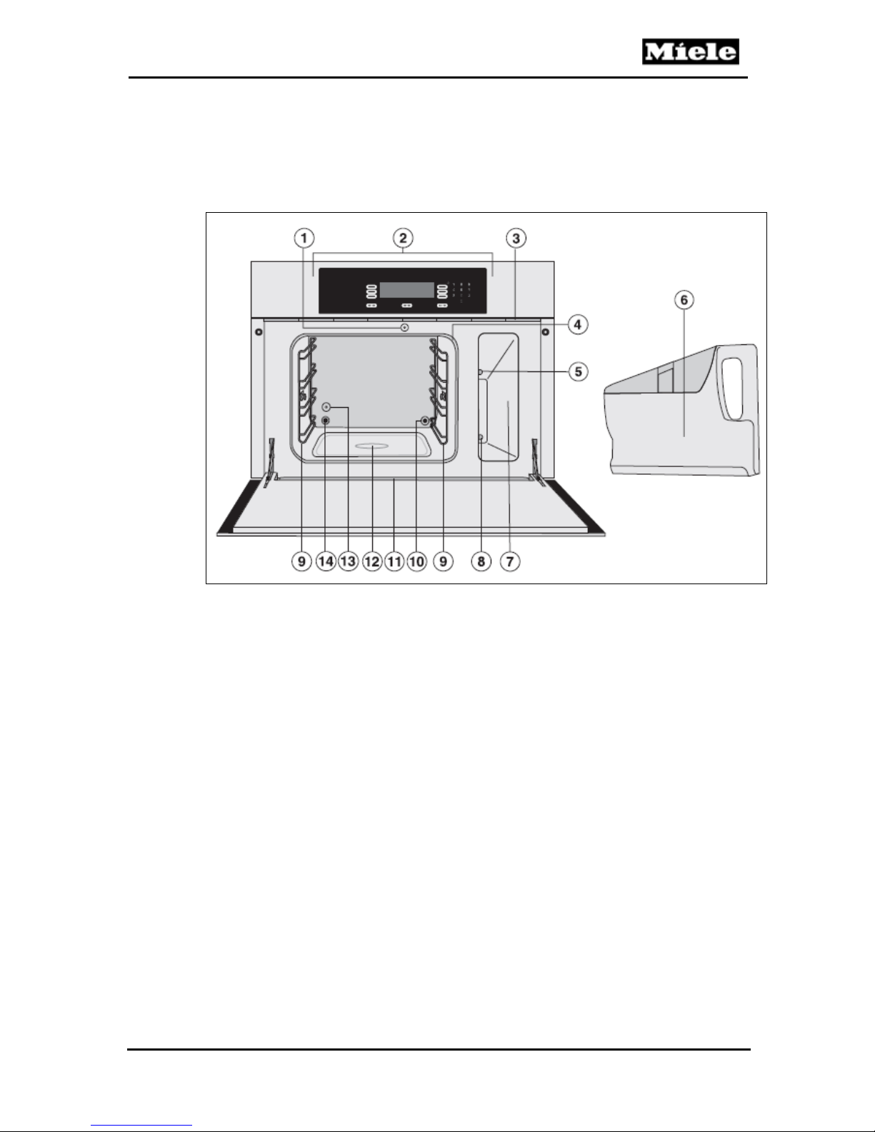
Figure D-1: Overview of DG 4080 (Front View) ...................................................................... 7
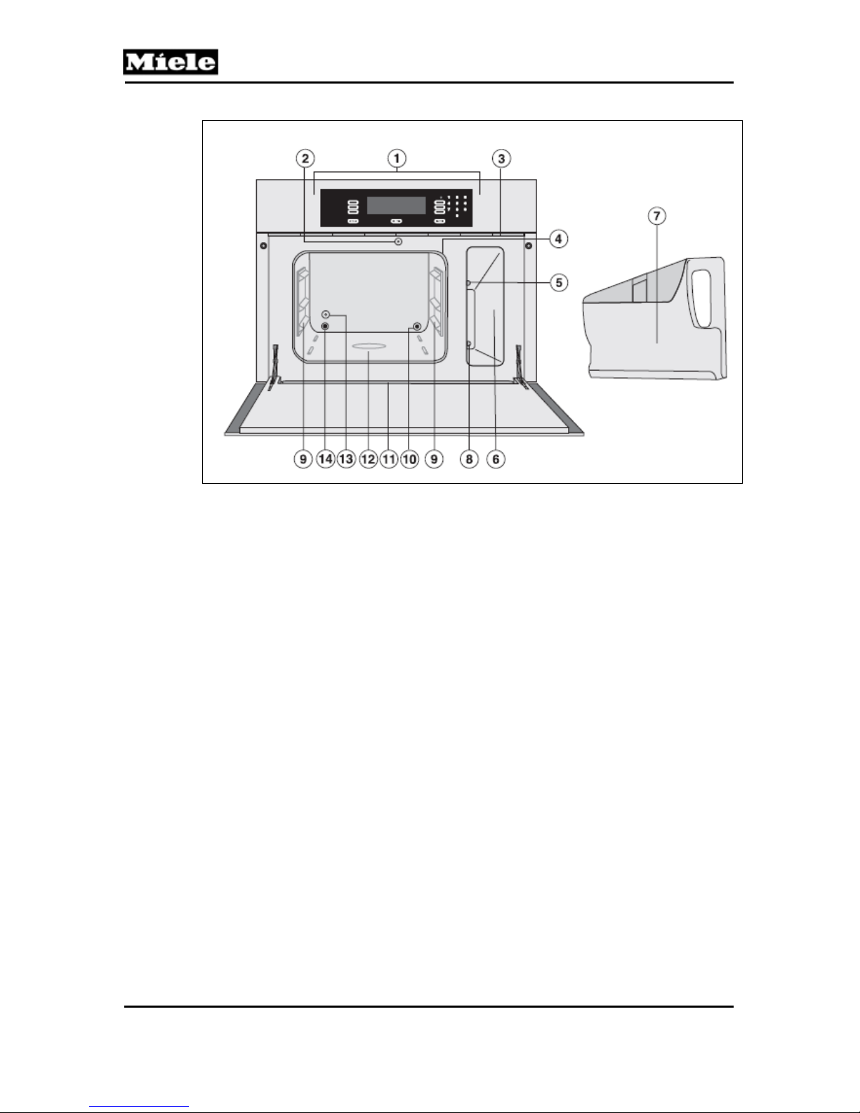
Figure D-2: Overview of DG 4082 (Front View) ...................................................................... 8
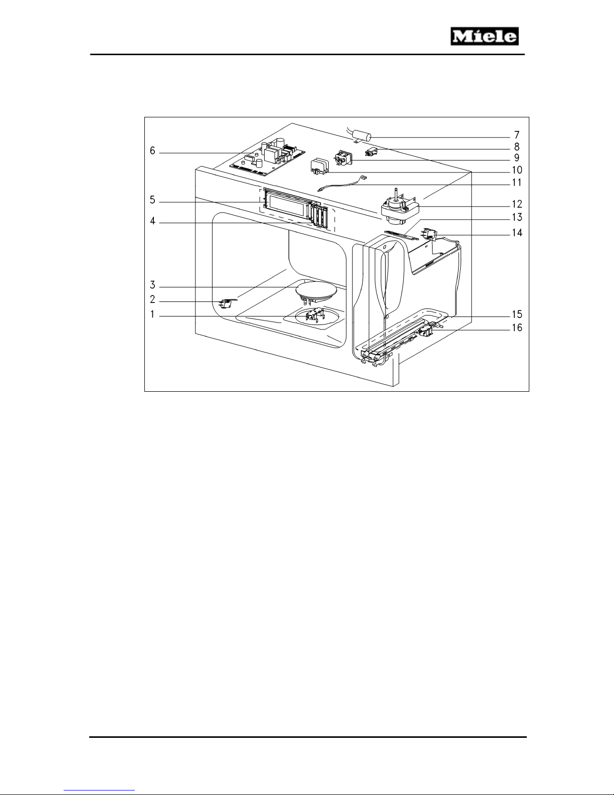
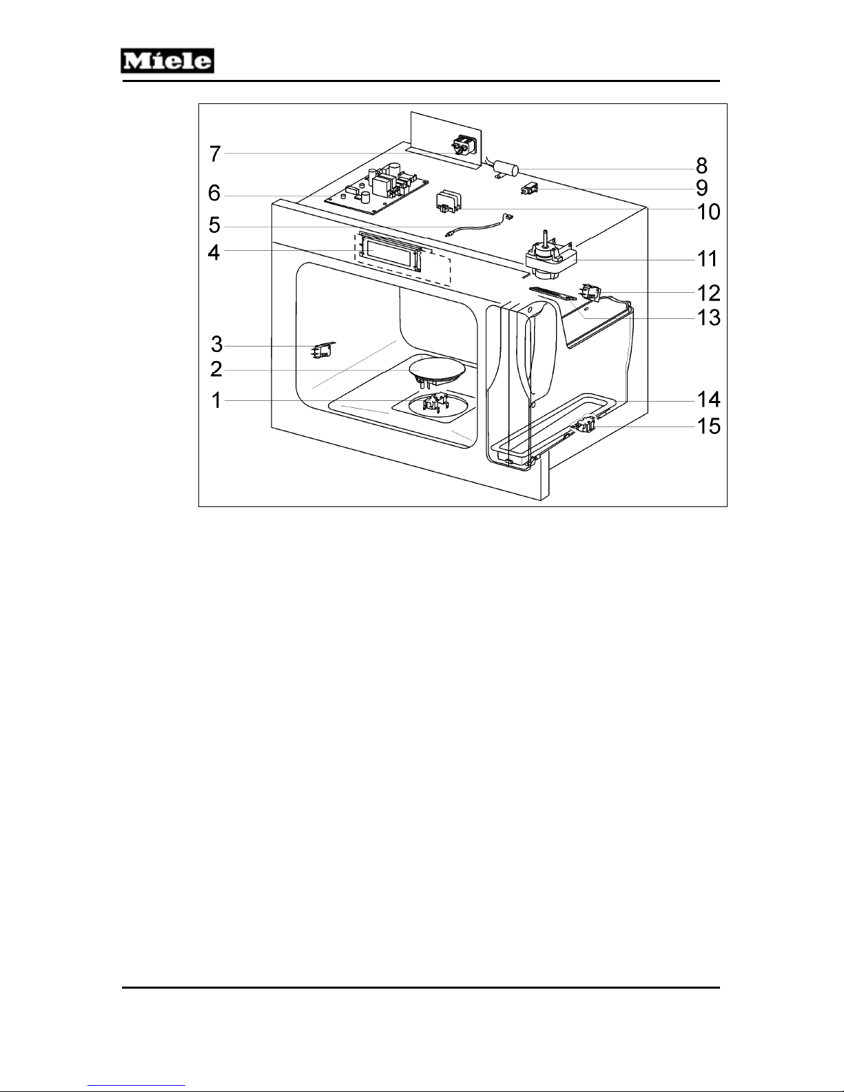
Figure D-3: DG 4080 Electrical Components .......................................................................... 9
Figure D-4: DG 4082 Electrical Components ........................................................................ 10
3
Page 4
DG 408x Steam Ovens
Technical Information
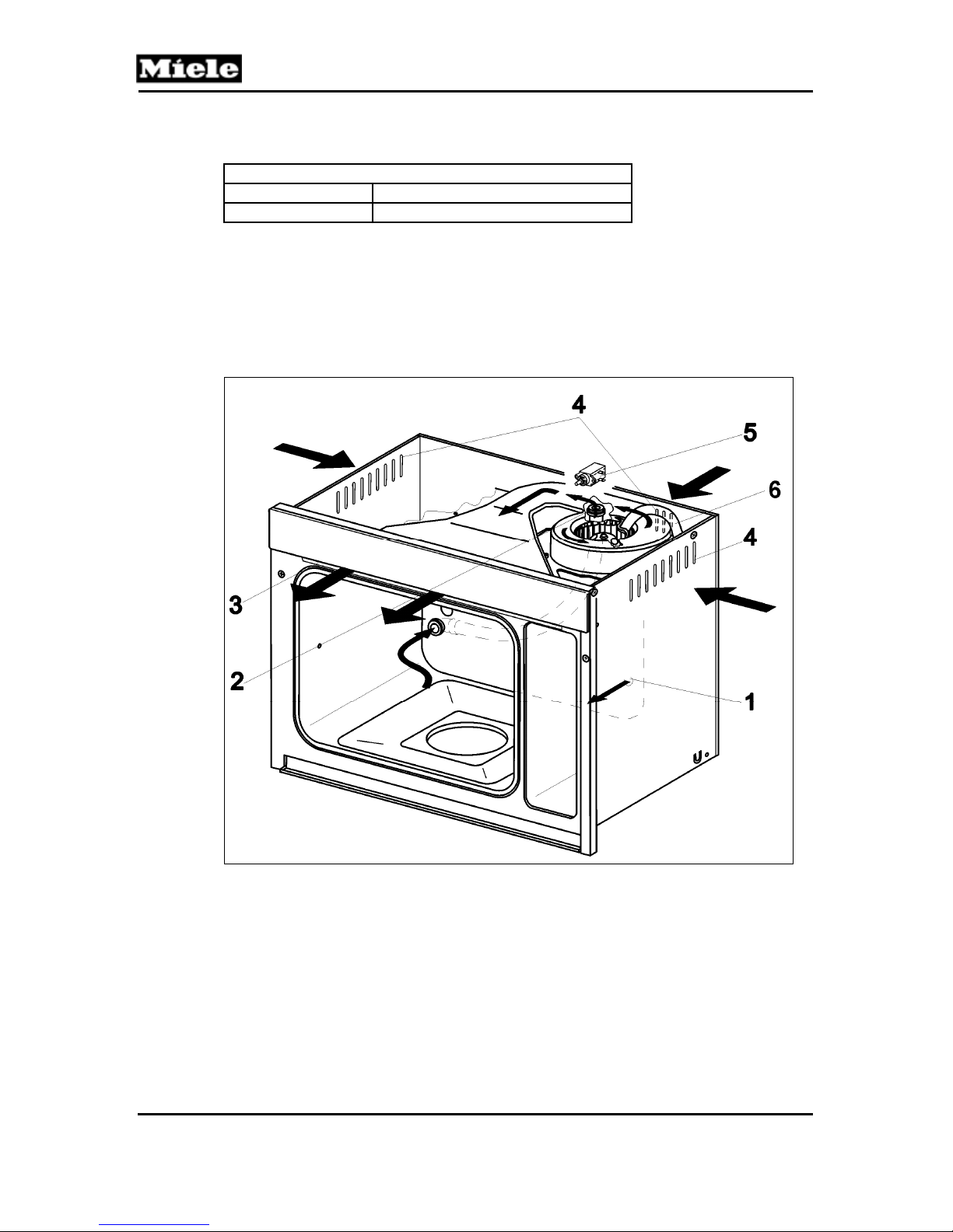
Figure 010-1: Ducting ............................................................................................................ 12
Figure 010-2: Screws on the Bottom of the Appliance (DG 4080) ........................................ 15
Figure 010-3: Appliance Retaining Screws ........................................................................... 15
Figure 010-4: Side Panel Screws (DG 4082 Shown) ............................................................ 16
Figure 010-5: Rear Panel Screws ......................................................................................... 16
Figure 010-6: Fan Screws and C-Clip ................................................................................... 17
Figure 010-7: Fan Connections ............................................................................................. 17
Figure 010-8: Door Contact Switch Removal ........................................................................ 18
Figure 010-9 Fascia Fastening Screws ................................................................................. 19
Figure 010-10: Upper Air Duct Retaining Screws and Hose ................................................. 19
Figure 010-11: Silicone Seal ................................................................................................. 20
Figure 010-12: Front Lugs ..................................................................................................... 20
Figure 020-1: Hinge Clamps ................................................................................................. 22
Figure 020-2: Door Removal ................................................................................................. 22
Figure 020-3: Door Handle Removal ..................................................................................... 23
Figure 030-1: Temperature Sensor R30 Removal (DG 4080) ............................................... 26
Figure 030-2: Temperature Sensor R30/10 Removal (DG 4082) .......................................... 26
Figure 030-3: Floor Heater Cover ......................................................................................... 27
Figure 030-4: Floor Heater Removal (DG 4080) ................................................................... 27
Figure 030-5: Floor Heater Removal (DG 4082) ................................................................... 28
Figure 040-1: Steam Generator ............................................................................................ 30
Figure 040-2: Hose Clamp .................................................................................................... 32
Figure 040-3: Steam Generator Heater Contacts ................................................................. 33
Figure 040-4: Housing Base ................................................................................................. 34
Figure 040-5: Steam Generator Temperature Regulator and Temperature Limiter .............. 35
Figure 040-6: Steam Duct Retaining Screws ........................................................................ 35
Figure 040-7: Removing the Top Cover from the Steam Duct Assembly .............................. 36
Figure 040-8: Reed Contact Float ......................................................................................... 37
Figure 040-9: Steam Generator Present Switch ................................................................... 37
Figure 060-1 Optical Interface ............................................................................................... 39
Figure 060-2: EPL700 Electronic – Overview (DG 4080 Shown) .......................................... 40
Figure 060-3: AC Power Electrical Circuit (DG 4080) ........................................................... 41
Figure 060-4: Fascia Panel Assembly (DG 4080) ................................................................. 51
Figure 060-5: Control Electronic Screws (DG 4080) ............................................................. 52
Figure 060-6: Fascia Panel (DG 4082) ................................................................................. 52
Figure 060-7: Removing the Control Electronic (DG 4082) ................................................... 53
List of Tables
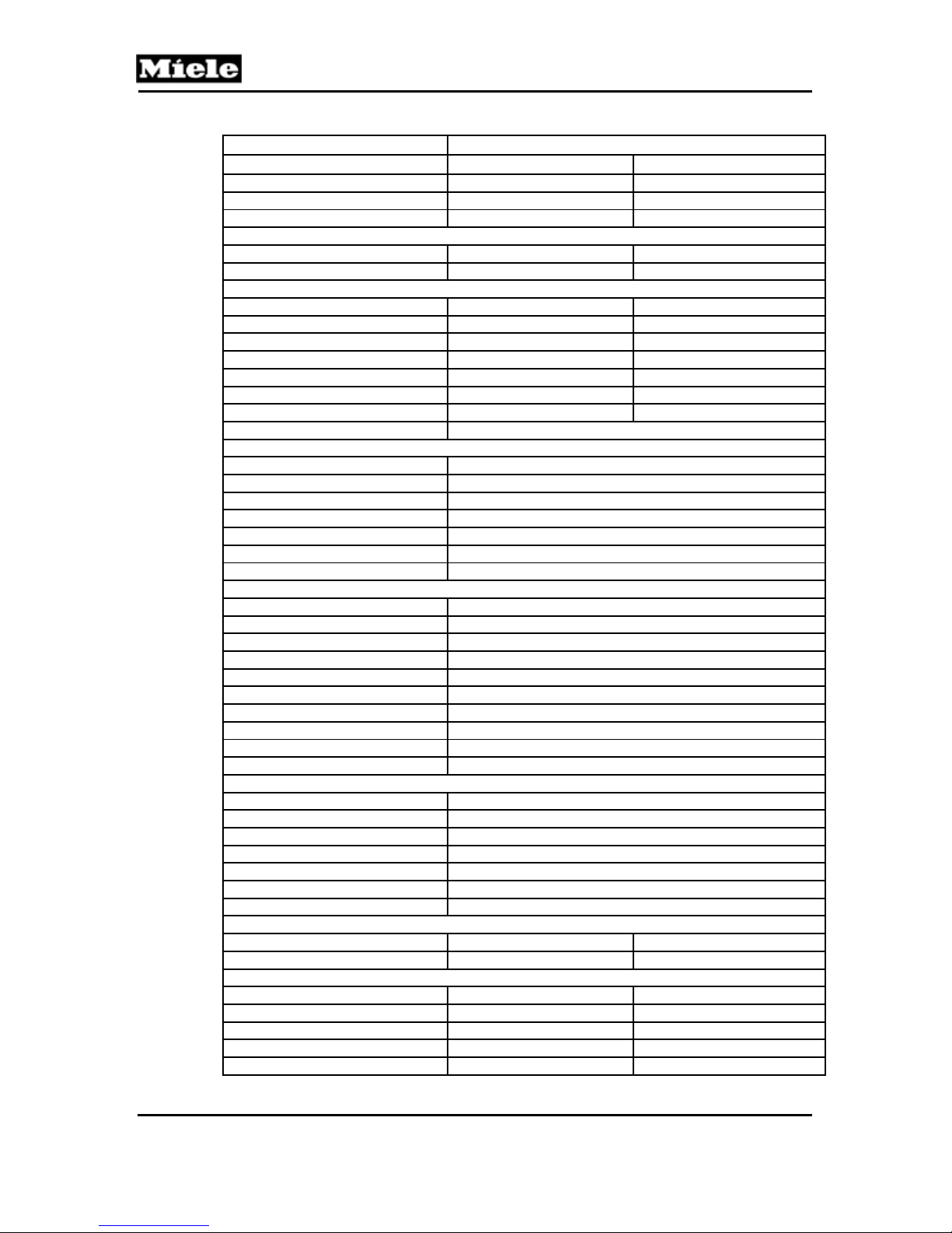
Table C-1: US Data Sheet ...................................................................................................... 6
Table 010-1: Cooling Fan Data ............................................................................................. 12
Table 030-1: Floor Heater Data ............................................................................................ 25
Table 030-2: PT 1000 Temperature Sensor Resistance Values ........................................... 25
Table 030-3: Threshold Temperatures .................................................................................. 25
Table 040-1: Steam Generator Data ..................................................................................... 30
Table 060-1: Fault Codes ...................................................................................................... 42
Table 060-2: Programming Mode ......................................................................................... 49
Table 060-3: Service Mode ................................................................................................... 50
4
Page 5
DG 408x Steam Ovens
A Warning and Safety Instructions
Service may only be carried out by qualified electricians and in keeping
with the appropriate safety regulations.
All applicable guidelines, accident prevention rules and laws must be
observed.
Before service or repair work can be started, all cables carrying power
must be safely disconnected.
Even when the appliance is disconnected from power, elements may
carry voltage.
A general visual check must be performed at all times.
A touch current measurement must be conducted on all conductive parts
that are not connected to ground.
Wear protective gloves and use the edge protection (mat. no. 5057680) to
prevent cuts by sharp edges.
B Modification History
When? Who? What?
2/2/2012 Jessica Naples Tech service bulletins added
5/27/2010 Jessica Naples Compilation for Website
Technical Information
C Technical Data
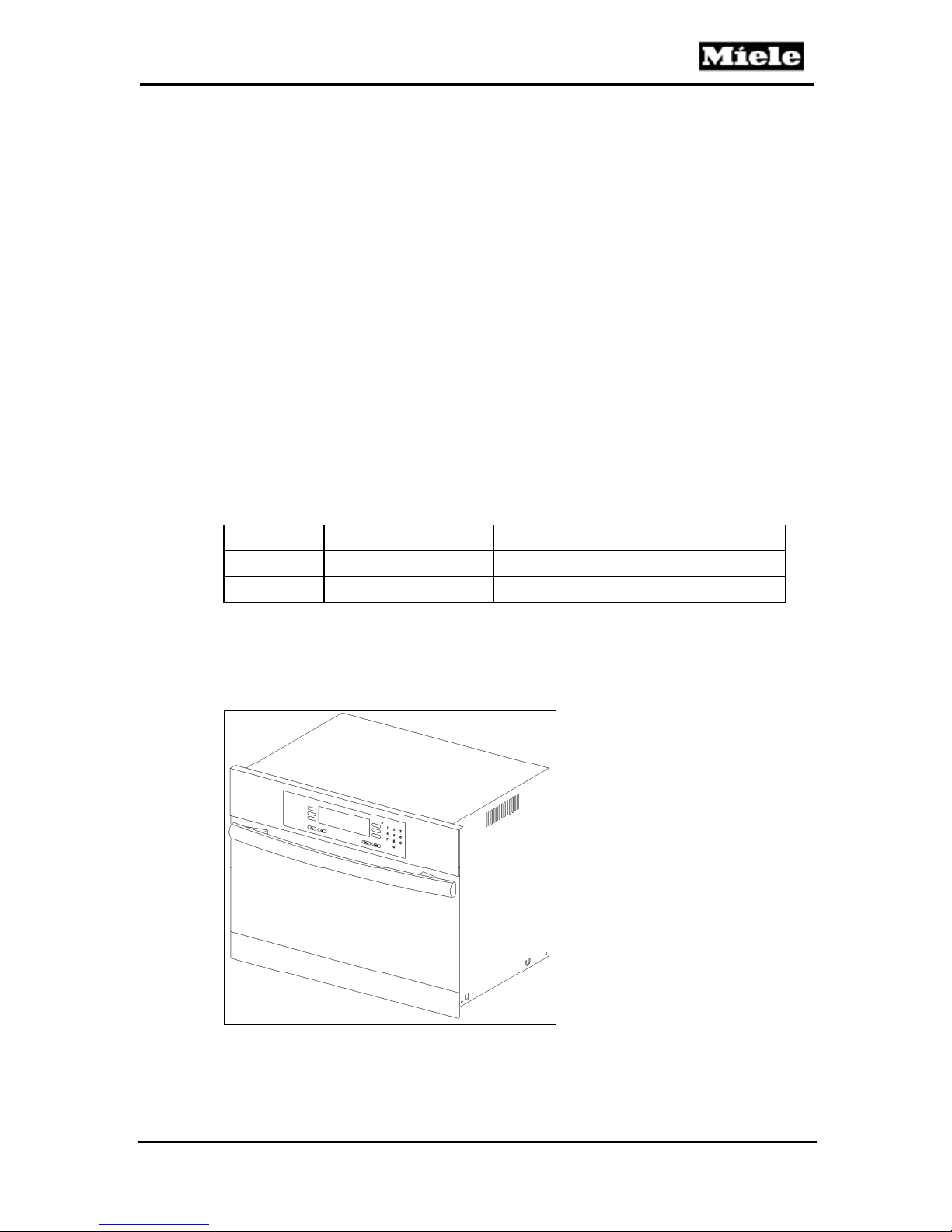
Figure C-1: DG 408x
5
Page 6
DG 408x Steam Ovens
Technical Information
Model
Design
Construction
Door stop
Dimensions
Appliance dimensions H x W x D 18.0” x 23.4” x 18.2” 17.9” x 23.6” x 16.7”
Depth with door open 30.8“ 30.8“
Niche dimensions
Height 17.6” – 17.8” 17.7”
Width 22.0” – 22.4” 22.0” – 22.4”
Depth min. 19.7” min. 19.7”
Weight
Capacity
Cavity height
Cavity base dimensions W x D
Levels in cavity (for racks)
Equipment
Vapor cooling system X
Water supply hookup —
System lock during operation X
Oven cavity floor heater X
Automatic steam reduction X
Recipe book X
Water tank capacity 1.3L
Operational features
Standard text display X
Recessed controls X
Temperature control 104 – 212°F
Automatic shutoff X
Fault indication X
Door contact switch X
Programmable cooking time X
Use of residual energy X
Steady water level indicator X
Warming function X
Operating modes
Cooking levels 4
Heat X
Defrost X
Descale X
Automatic programs X
Own favorites X
Interference suppressed X
Heaters
Floor heater 300W 350W
Steam generator 2200W 2200W
Power connection
Voltage (208) 240 VAC 240VAC
Frequency 60Hz 60Hz
Electrical connection NEMA 6-15 NEMA 6-15
Connected load 2500W 2700W
Fuse (circuit breaker) rating 15A 15A
DG 4080 DG 4082
Steam oven Steam oven
Built-in Built-in
Bottom Bottom
59.4 lbs 61.8 lbs
0.88 cu. ft. 0.88 cu. ft.
9.4” 9.5”
13.2” x 14.4” 13.2” x 14.4”
4 (incl. 1 for condensate tray)
Table C-1: US Data Sheet
6
Page 7
DG 408x Steam Ovens
D Component Layouts
1 Appliance Overviews
Technical Information
Figure D-1: Overview of DG 4080 (Front View)
1
Door release
2
Control panel
3
Air vent
4
Door seal
5
Steam channel
6
Steam generator (with insert)
7
Steam generator compartment
8
Steam generator electrical connection
9
Runners (4)
10
Steam port
11
Drip channel
12
Floor heater
13
Temperature sensor
14
Vent port
7
Page 8
Technical Information
DG 408x Steam Ovens
Figure D-2: Overview of DG 4082 (Front View)
1
Control panel
2
Door release
3
Air vent
4
Door seal
5
Steam channel
6
Steam generator compartment
7
Steam generator (with insert)
8
Steam generator electrical connection
9
Runners
10
Steam port
11
Drip channel
12
Floor heater
13
Temperature sensor
14
Air vent
8
Page 9
DG 408x Steam Ovens
–
–
–
–
2 Electrical Components
Technical Information
Figure D-3: DG 4080 Electrical Components
1
(2F1, 2F8) Floor heater temperature regulator (239°F) and
temperature limiter (402°F)
2
(S4) Door contact switch
3
(R28) Floor heater
4
(1N1) Selection electronic EW
5
(2N1) Control electronic EPX
6
(3N1) Power electronic EPL
(1K1/1, 2K1/1) Steam generator relay (not shown)
(K1/3) Floor heater relay (not shown)
(K1/5) Fan relay (not shown)
(K1/61) Release element relay (not shown)
7
(Z2) Interference suppression capacitor
8
(Y56) Release element
9
(X2) Socket for power cable
10
(X7) Plug strip
11
(R30) PT1000 temperature sensor
12
(M2) Fan
13
(S12) Water level float switch (PCB)
14
(S84) Steam generator present switch
15
(1R25, 2R25) Steam generator heater elements
16
(1F1, 1F8) Steam generator temperature regulator (410°F)
and temperature limiter (568°F)
9
Page 10
Technical Information
DG 408x Steam Ovens
Figure D-4: DG 4082 Electrical Components
1
(2F1, 2F8) Floor heater temperature regulator (239°F) and
temperature limiter (402°F)
2
(R28) Floor heater
3
(S4) Door contact switch
4
(2N1) Control/selection electronic EW
5
(R30/10) PT1000 temperature sensor
6
(1N1) Power electronic
7
(X2) Power socket
8
(Z2) Interference suppression capacitor
9
(Y56) Release element
10
(X7) Plug strip
11
(M2/1) Cooling fan
12
(S84) Steam generator switch
13
(S12) Water level float switch (PCB)
14
(1R25, 2R25) Steam generator heater
15
(1F1, 1F8) Steam generator temperature regulator (410°F)
and temperature limiter (568°F)
10
Page 11
DG 408x Steam Ovens
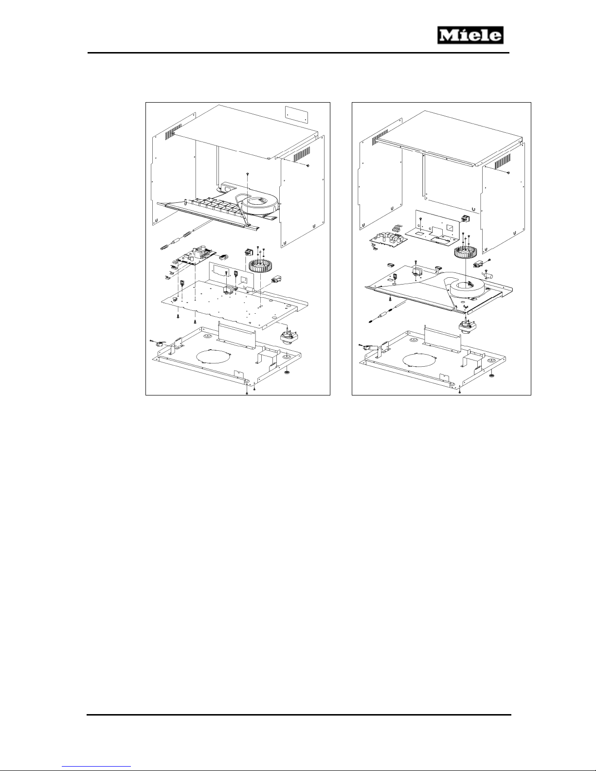
010 Casing
Technical Information
DG 4080 DG 4082
11
Page 12
Technical Information
1 Technical Data
Cooling fan M2 (DG 4080) or M2/1 (DG 4082)
Voltage 240VAC, 60Hz
Output 15W
Table 010-1: Cooling Fan Data
2 Function
2.1 Air and Vapor Ducting
DG 408x Steam Ovens
Figure 010-1: Ducting
1
Steam inlet
2
Oven vent hose
3
Cool air/vapor outlet
4
Cool air inlet
5
Release element for steam reduction (door opener)
6
Steam vent hose
During the cooking process, fresh steam is pumped into the oven cavity
(Figure 010-1, Item 1). The generated vapors are pushed out through the
vent opening. Through a hose at the rear of the oven cavity, the vapors move
12
Page 13
DG 408x Steam Ovens
to the air duct (Figure 010-1, Item 2). The fan draws in cool air through the air
vents in the housing, and the cool air mixes with the vapors in the air duct
(Figure 010-1, Item 4). The cool air/vapor mix is expelled through the gap
between the fascia and the oven cavity (Figure 010-1, Item 3). Excess steam
from the steam generator is carried directly to the fan via the vent hose
(Figure 010-1, Item 6) and pushed out at the front of the appliance. Shortly
before cooking time is up, relay K1/61 activates the release element, which
causes a metal rod to slowly open the door a crack. This reduces the steam
in the oven cavity. See Figure 010-1, Item 5. Once the buzzer sounds to
indicate the end of cooking time, the door slowly closes.
2.2 Fan Coastdown
To reduce the vapors that are still in the oven cavity after cooking has ended,
the fan continues running after the appliance is switched off.
This prevents
steam from settling on the fascia of the cabinetry when opening the door
condensate from forming in the housing by residual steam.
Coastdown duration depends on whether or not the steam generator has
been removed from the appliance after the cooking process. Warm cooked
food in the appliance delays the cooling and leads to a longer coastdown
time. Coastdown time is not adjustable!
Technical Information
If steam generator was removed: Coastdown takes at least 8 minutes. If
after the first 8 minutes the interior temperature has not dropped below
113°F (45°C), then the coastdown time is extended for an additional 8
minutes until the interior temperature drops below 113°F (45°C).
If steam generator was not removed: Coastdown takes at least 60
minutes. If after the first 60 minutes the interior temperature has not
dropped below 113°F (45°C), then the cooldown time is extended for an
additional 8 minutes until the interior temperature drops below 113°F
(45°C).
2.3 Door Contact Switch (S24)
If the door is opened during the cooking process, the door contact switch
signals the control electronic, which switches off the steam generator heater
(1R25, 2R25).
Note:
With the door open a crack, new cooking selections can be made.
However, the steam generator heater will not be switched on for
approximately one to two minutes.
2.4 Release Element (Y56) for Steam Reduction
Shortly before cooking time is up, relay K1/61 activates the release element,
which slowly opens the door a crack. This reduces the steam in the oven
cavity. After the buzzer sounds to signal the end of cooking time, the door
slowly closes again.
While the door is open a crack, new cooking selections can be made.
However, the steam generator heater will not be switched on for
approximately one to two minutes.
13
Page 14
Technical Information
3 Fault Repair
3.1 Fan Coastdown Too Long
Symptom:
Coastdown is at least 8 minutes and can be more than 60 minutes.
Cause:
Steam generator remains in the appliance after cooking has ended.
Coastdown duration depends on whether or not the steam generator has
been removed from the appliance after the cooking process. Warm cooked
food in the appliance delays the cooling and leads to a longer coastdown.
Coastdown time is not adjustable!
Steam generator was removed: Coastdown takes at least 8 minutes. If
after the first 8 minutes the interior temperature has not reduced to below
113°F (45°C), then the coastdown is extended for an additional 8 minutes
until the interior temperature drops below 113°F (45°C).
Steam generator was not removed: Coastdown takes at least 60
minutes. If after 60 minutes the oven cavity temperature has not dropped
below 45°C, the coastdown duration is extended in increments of 8
minutes until the oven cavity temperature is below 45°C. In addition, if
food remains in the oven cavity, the cooling-off period is delayed and
causes a longer coastdown.
DG 408x Steam Ovens
Remedy:
1. Remove steam generator and cooked food after a cooking program.
2. Leave door open.
3. Empty steam generator before inserting it again.
3.2 Top Clearance Too Small When Combined with Warming Drawer (DG 4080)
Symptom:
When combining the appliance with the built-in EGW 4000 warming drawer,
the clearance on top to the cabinetry is too small. This becomes particularly
obvious if other Miele machines are built in next to it.
Cause:
Two screw heads at the bottom of the appliance meet exactly with rivets at
the top of the EGW 4000 warming drawer. This causes the appliance to be
positioned slightly higher, and the gap within the cabinetry to be insufficient to
allow proper installation.
Series modification:
The position of the rivets on the warming drawer has been changed so that
the screw caps will not meet the rivets.
Remedy:
Note:
Both screws can be permanently removed, since they are only used during
production and will not have any adverse effects if removed.
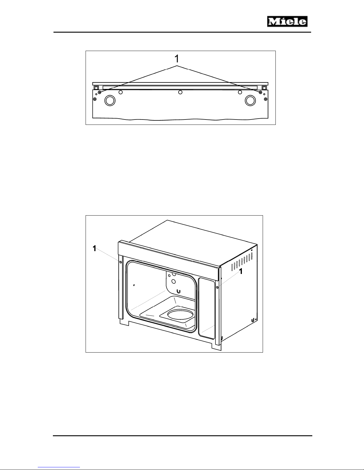
Remove both screws (Figure 010-2, Item 1).
14
Page 15
DG 408x Steam Ovens
Technical Information
Figure 010-2: Screws on the Bottom of the Appliance (DG 4080)
4 Service
4.1 Removing the Appliance from its Niche
1. Open the door.
2. Take the steam generator and equipment out of the oven cavity.
3. Remove the appliance retaining screws (Figure 010-3, Item 1).
4. Slide the appliance out of its niche.
5. Disconnect the appliance from the power supply.
Figure 010-3: Appliance Retaining Screws
4.2 Removing the Side Panels
1. Uninstall the appliance. See Section 010-4.1.
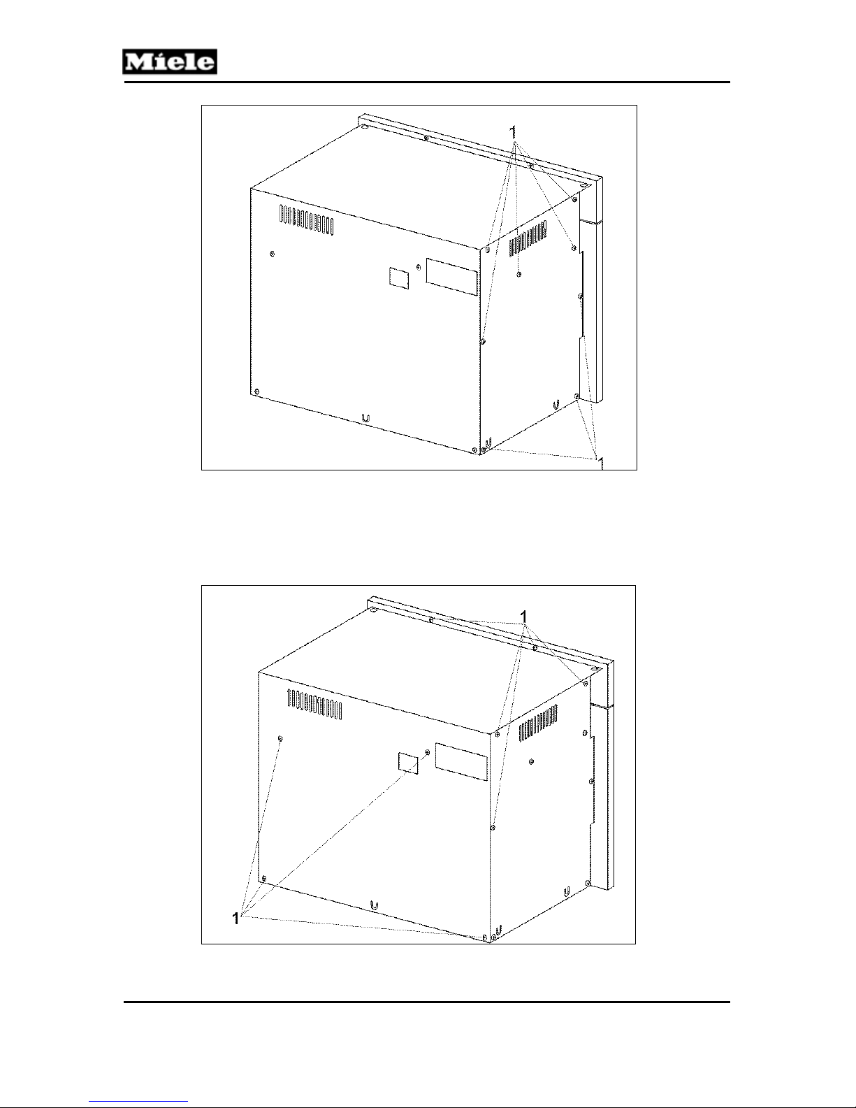
2. Remove the side panel screws; see Figure 010-4, Item 1.
3. Take off the side panel(s).
15
Page 16
Technical Information
DG 408x Steam Ovens
Figure 010-4: Side Panel Screws (DG 4082 Shown)
4.3 Rear Panel Removal
1. Uninstall the appliance. See Section 010-4.1.
2. Remove the T20 screws securing the rear panel (Figure 010-5, Item 1).
3. Remove the rear panel.
Figure 010-5: Rear Panel Screws
16
Page 17
DG 408x Steam Ovens
4.4 Fan (M2/1) Removal
1. Uninstall the appliance. See Section 010-4.1.
2. Remove the right side panel. See Section 010-4.2.
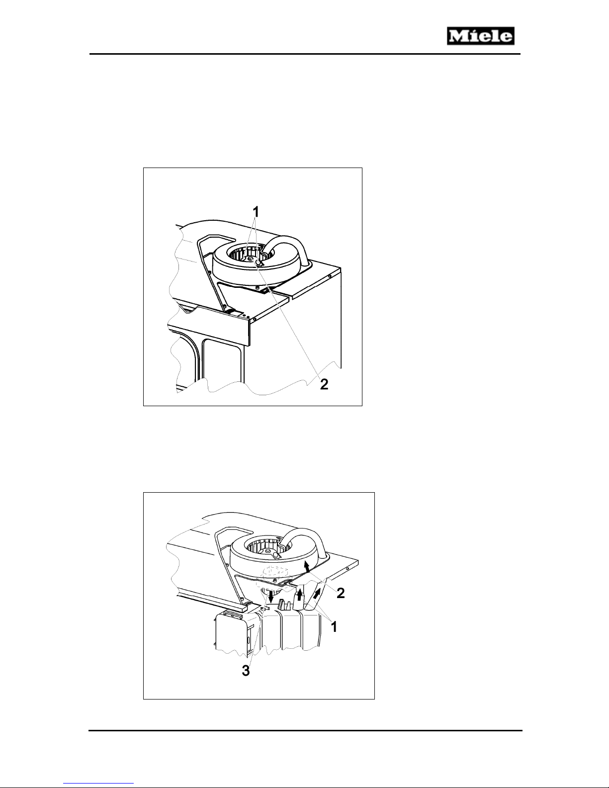
3. Remove the screws securing the fan (Figure 010-6, Item 1).
4. Remove the C-clip securing the blower wheel (Figure 010-6, Item 2).
5. Turn the blower wheel as necessary to permit access to the motor
mounting screws.
Technical Information
Figure 010-6: Fan Screws and C-Clip
6. Disconnect hoses (Figure 010-7, Item 1) as necessary to access the fan
motor from the underside of the air duct.
7. Raise the air duct slightly (Figure 010-7, Item 2) and take out the fan
motor (Figure 010-7, Item 3).
8. Disconnect all fan connections.
Figure 010-7: Fan Connections
17
Page 18
Technical Information
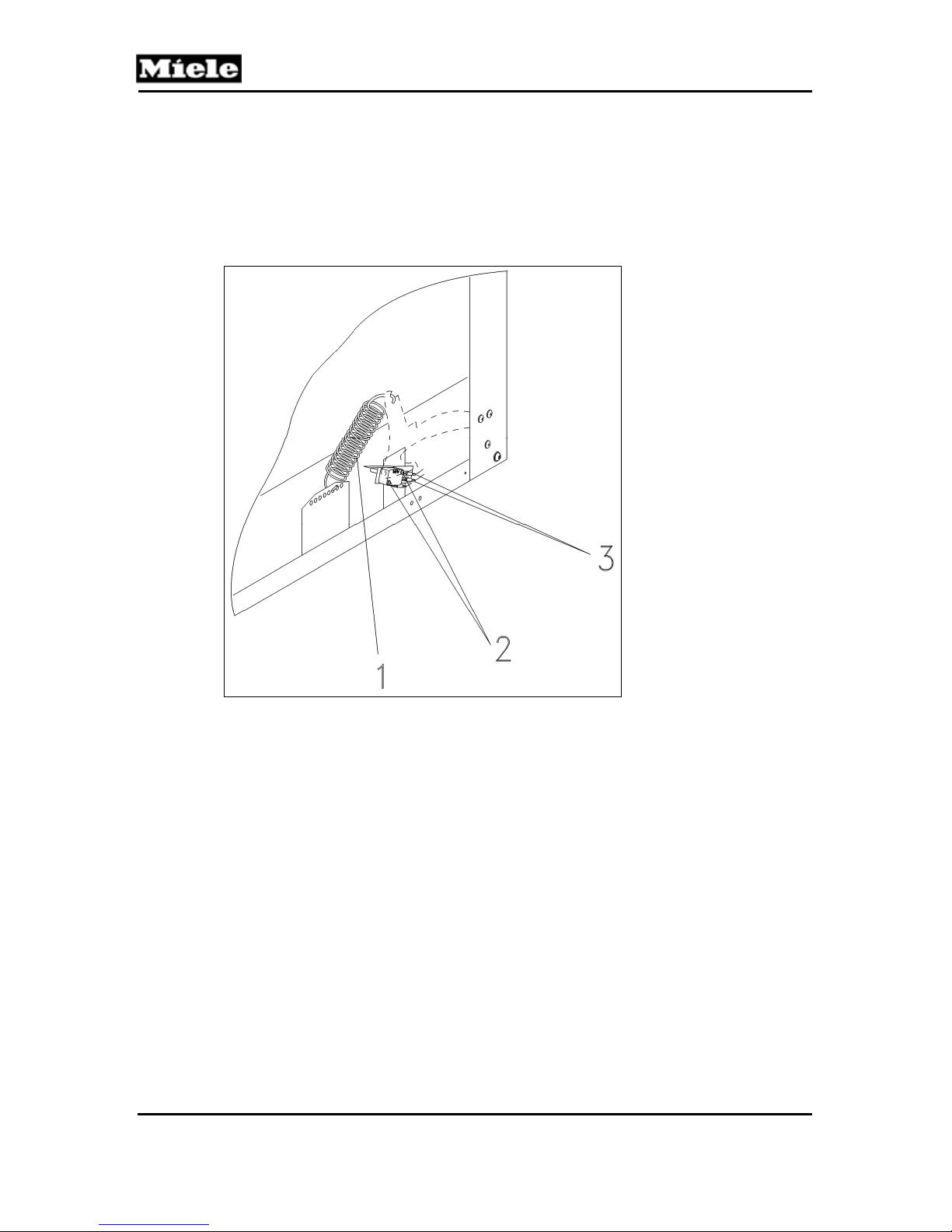
4.5 Removing the Door Contact Switch (S24)
1. Uninstall the appliance. See Section 010-4.1.
2. Remove the left side panel. See Section 010-4.2.
3. Unhook the door spring (Figure 010-8, Item 1).
4. Remove the two Phillips screws (Figure 010-8, Item 2).
5. Remove the switch from its support plate.
6. Disconnect the switch connections (Figure 010-8, Item 3).
DG 408x Steam Ovens
Figure 010-8: Door Contact Switch Removal
4.6 Upper Air Duct Removal
1. Take the steam generator and equipment out of the oven cavity.
2. Uninstall the appliance. See Section 010-4.1.
3. Remove the side panels. See Section 010-4.2.
4. Remove the rear panel. See Section 010-4.3.
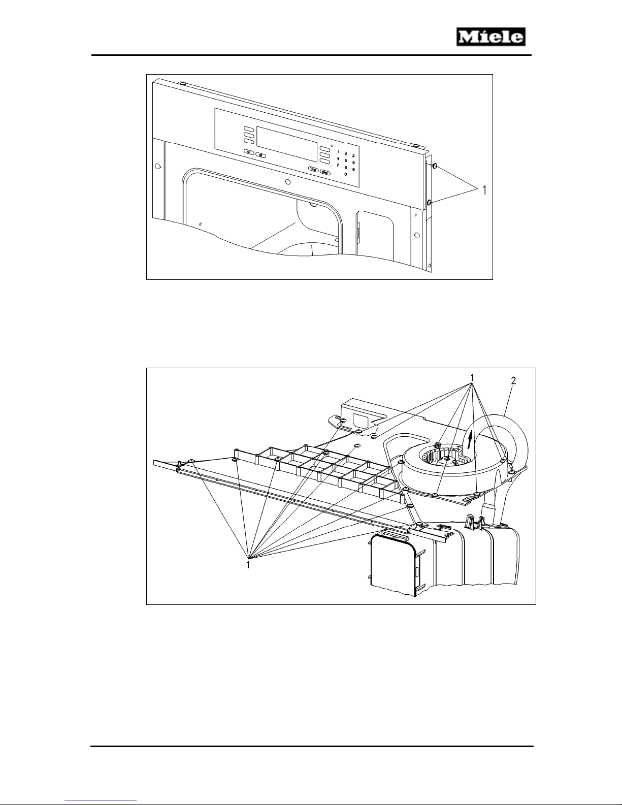
5. Remove four screws securing fascia panel (Figure 010-9, Item 1, left and
right sides).
18
Page 19
DG 408x Steam Ovens
Technical Information
Figure 010-9 Fascia Fastening Screws
6. Remove the fascia/support panel assembly.
7. Disconnect plug ST3 from the electronic, and remove wiring from the top
of the ducting.
8. Remove 17 screws (Figure 010-10, Item 1).
9. Disconnect the hose (Figure 010-10, Item 2).
Figure 010-10: Upper Air Duct Retaining Screws and Hose
10. Using an appropriate tool, slice open the silicone seal (Figure 010-11, Item 1).
19
Page 20
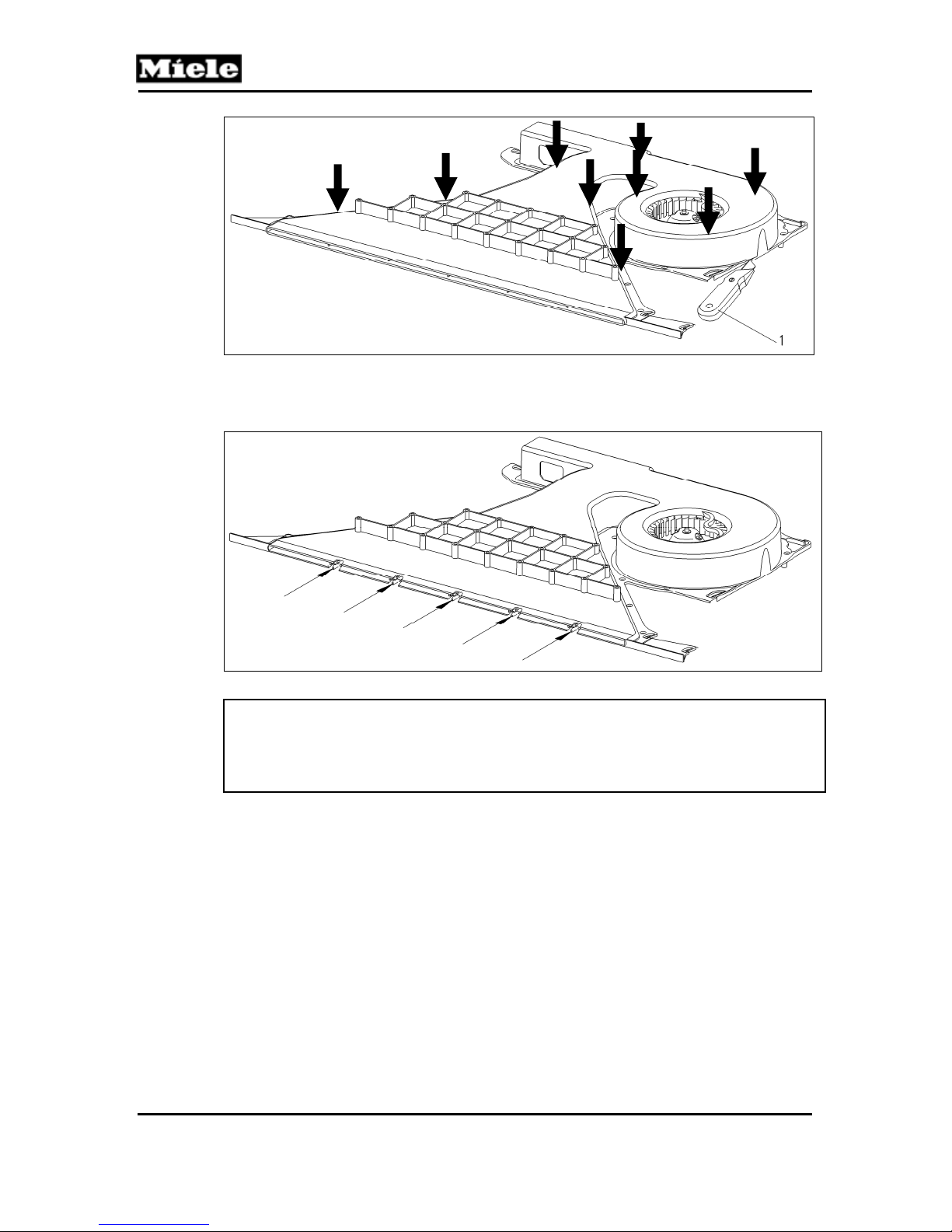
Technical Information
DG 408x Steam Ovens
Figure 010-11: Silicone Seal
11. Slide the upper duct assembly back to release the front lugs from the
frame (Figure 010-12). Lift the assembly upward to remove.
Figure 010-12: Front Lugs
Warning!
When re-installing the upper air duct, the silicone has to be replaced to seal
the air duct.
The front lugs on the upper air duct are fragile and break off easily!
4.7 Fan Wheel Removal
1. Take the steam generator and equipment out of the oven cavity.
2. Uninstall the appliance. See Section 010-4.1.
3. Remove the side panels. See Section 010-4.2.
4. Remove the rear panel. See Section 010-4.3.
5. Remove the upper air duct; see Section 010-4.6.
6. Remove the C-clip (Figure 010-6, Item 2).
7. Remove the fan wheel.
20
Page 21
DG 408x Steam Ovens
020 Door
Technical Information
DG 4080 DG 4082
21
Page 22
Technical Information
3 Fault Repair
3.1 Whistling Sound When Closing the Door
Symptom:
When the oven is in a heated state and the oven door is opened and then
closed again, there is a whistling sound.
Cause:
When opening the door, cool air gets into the oven cavity. The cool air expands in
the hot oven cavity and slightly increases the pressure when the door is closed.
Remedy:
None. The appliance is in good working order. The whistling sound cannot be
eliminated.
4 Service
4.1 Door Removal
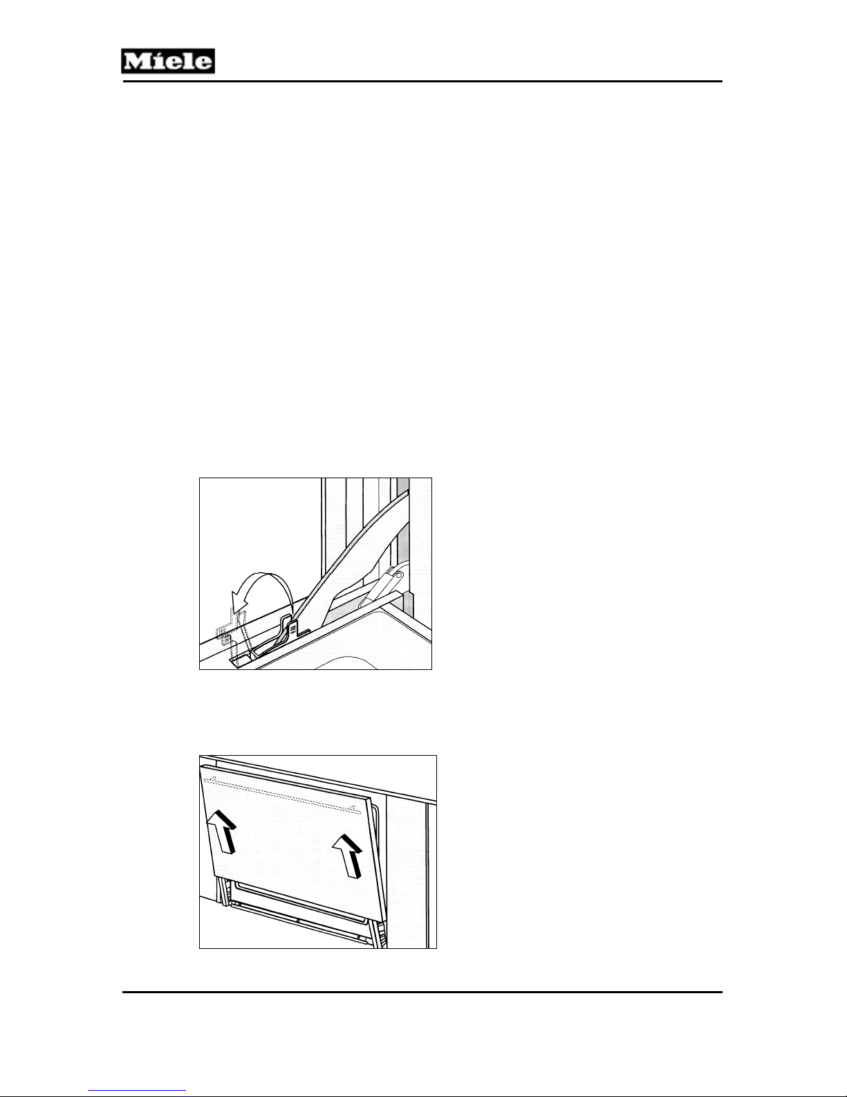
1. Open the door to the fully open position.
2. Flip up the clamp arms on both hinges (Figure 020-1).
DG 408x Steam Ovens
Figure 020-1: Hinge Clamps
3. Slowly close the door until the clamps are touching the frame of the oven interior.
4. While holding the door with both hands, lift the door until the hinges
disengage. Remove the door. See Figure 020-2.
Figure 020-2: Door Removal
22
Page 23
DG 408x Steam Ovens
4.2 Installing the Door
1. Place the door on the hinges and slide it down.
2. Open the door fully.
3. Push the clamps back down.
4. Close the door.
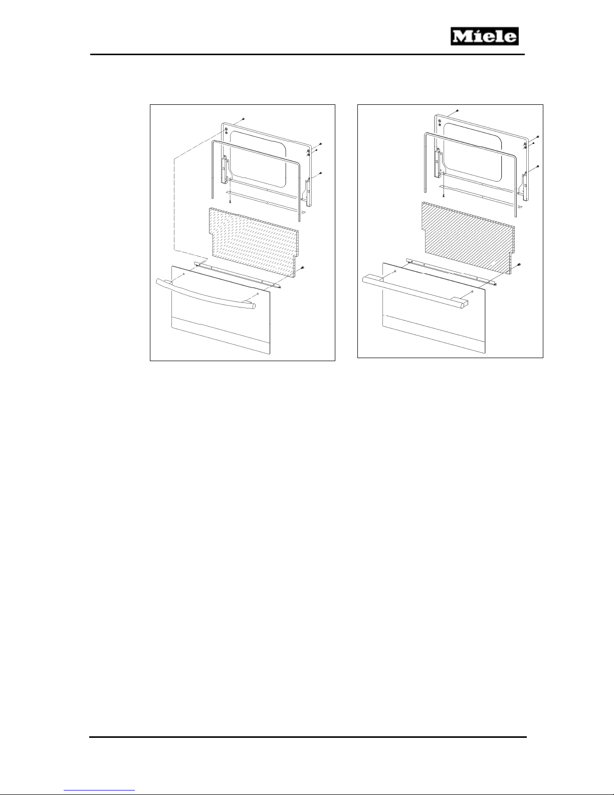
4.3 Door Disassembly
1. Door removal
2. Lay the door on a soft work surface (mat or cloth), with the inner side
facing up.
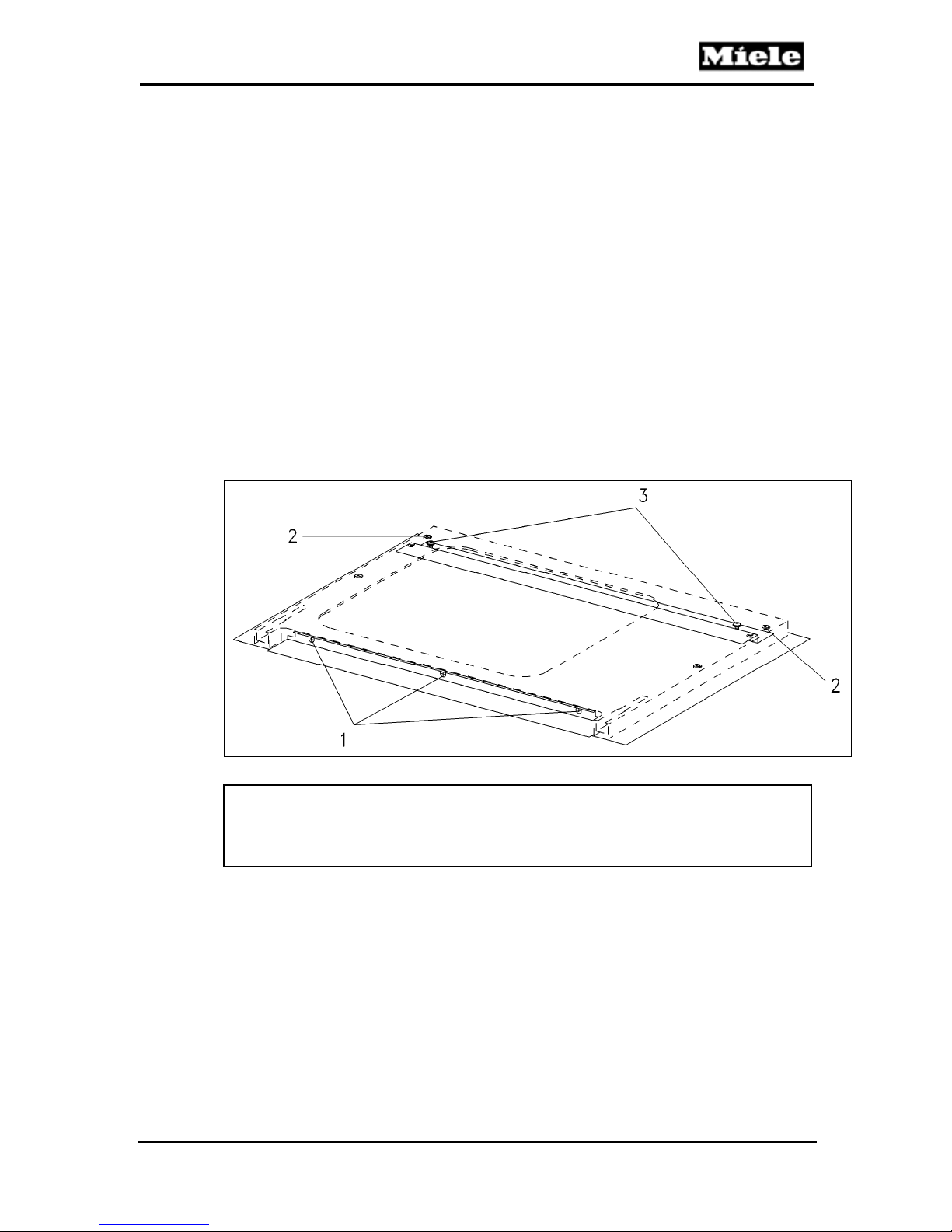
3. Remove 3 Phillips screws on the bottom edge of the inner door (Figure
020-3, Item 1).
4. DG 4082 only: Remove 4 Phillips screws from the top of the inner door
(Figure 020-3, Item 2).
5. Take off the inner door.
6. Remove the 2 Phillips screws securing the door handle (Figure 020-3,
Item 3).
7. Remove the door handle.
Technical Information
Figure 020-3: Door Handle Removal
Note:
When assembling the door, make sure to carefully position the seal running
along the edges of the inner door. Ensure that the seal is seated and
remains flush with the edge of the glass.
23
Page 24
Technical Information
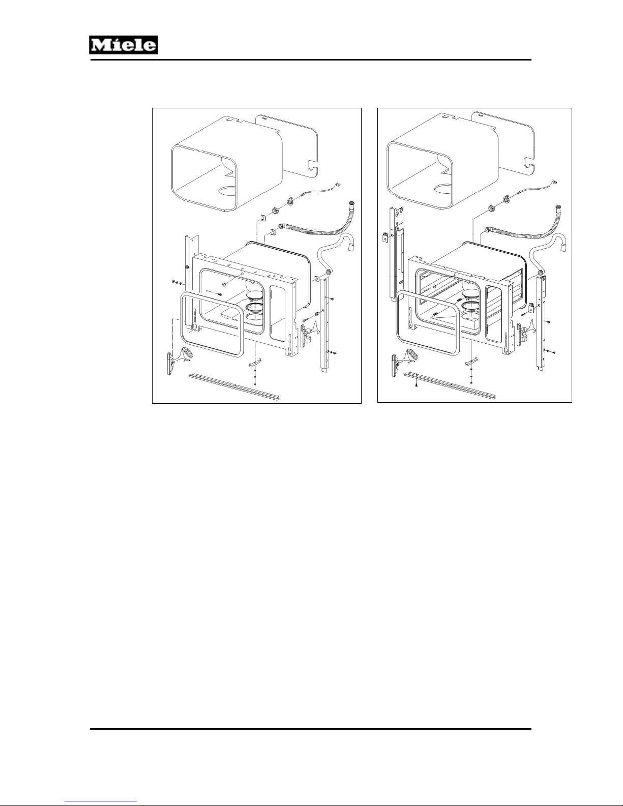
030 Oven Cavity
DG 408x Steam Ovens
DG 4080 DG 4082
24
Page 25
DG 408x Steam Ovens
Technical Information
1 Technical Data
Floor heater (R28)
Output power 300W (DG 4080); 350W (DG 4082)
Table 030-1: Floor Heater Data
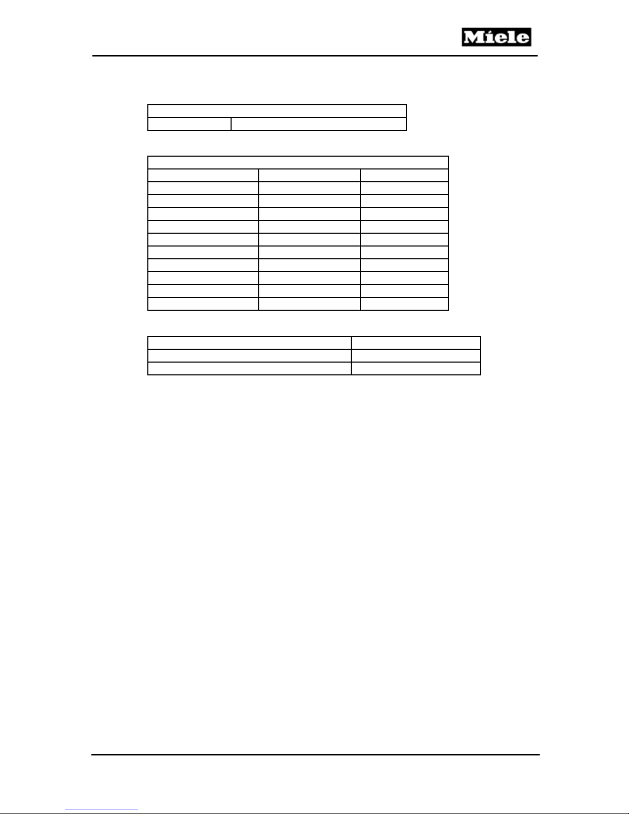
PT 1000 Temperature Sensor (R30 or R30/10)
Temperature (°C) Temperature (°F) Resistance (Ω)
0 32 1000
20 68 1078
25 77 1097
30 86 1117
50 122 1194
100 212 1385
150 302 1573
200 392 1758
250 482 1941
300 572 2120
Table 030-2: PT 1000 Temperature Sensor Resistance Values
Threshold temperature
Floor heater temperature regulator (2F1) 239°F
Floor heater temperature limiter (2F8) 402°F
Table 030-3: Threshold Temperatures
2 Function
2.1 Floor Heater Element
The floor heater element is located in the center of the oven cavity floor, and
prevents water from condensing and accumulating at the bottom of the oven cavity.
2.2 PT 1000 Temperature Sensor (R30 or R30/10)
The PT 1000 temperature sensor is a printed circuit board (PCB) which is
used to provide the electronic with data to calculate the oven cavity
temperature. The sensor’s resistance increases as the temperature
increases. Details are listed in Table 030-2.
4 Service
4.1 PT 1000 Temperature Sensor (R30 or R30/10) Removal
1. Take the steam generator and equipment out of the oven cavity.
2. Uninstall the appliance. See Section 010-4.1.
3. Remove the side panels. See Section 010-4.2.
4. Remove the rear panel. See Section 010-4.3.
5. Slide or move insulation as necessary.
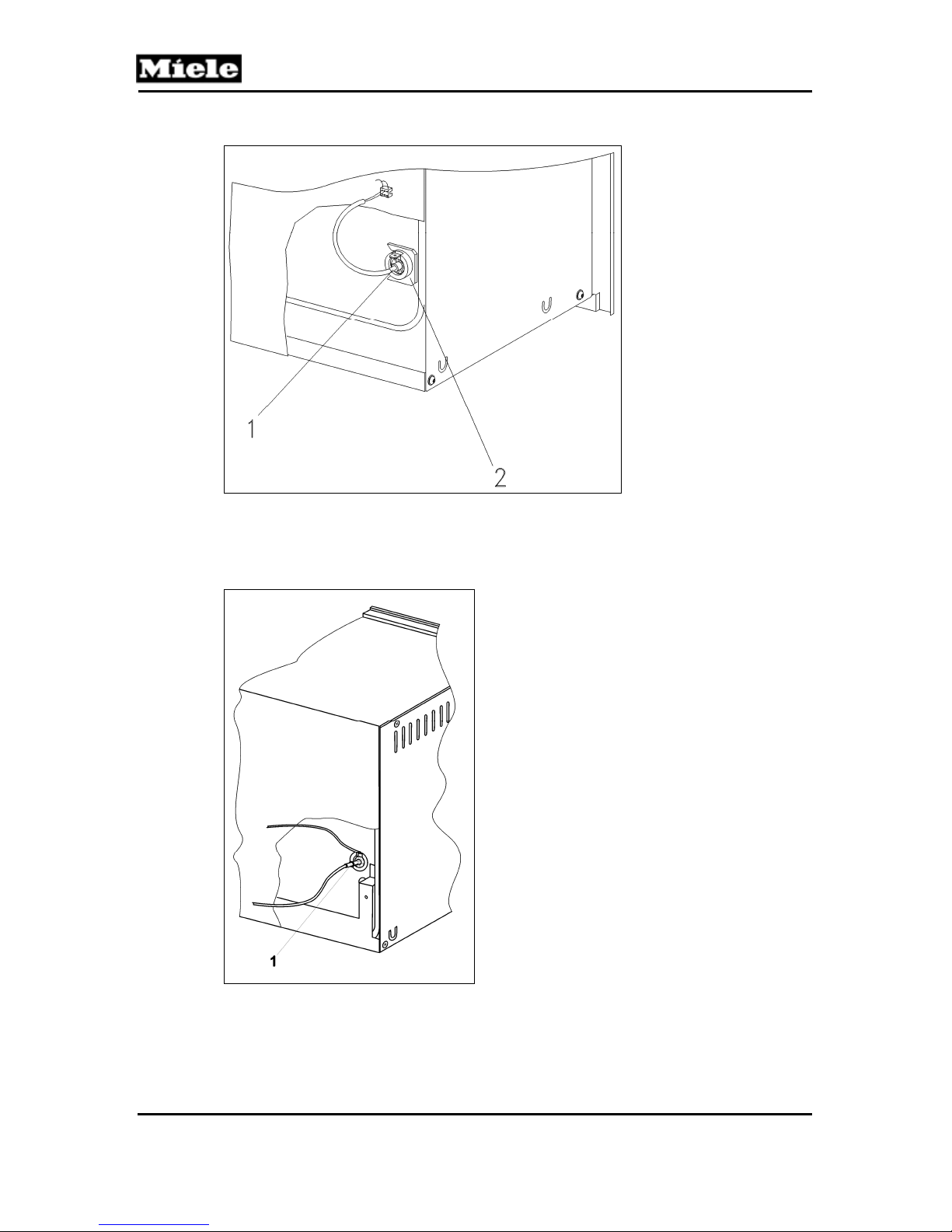
6. DG 4080: Disconnect the temperature sensor (Figure 030-1, Item 1) from
the power electronic. Take off the retaining clip (030-Figure 1, Item 2).
25
Page 26
Technical Information
Remove the temperature sensor from its seal.
DG 408x Steam Ovens
Figure 030-1: Temperature Sensor R30 Removal (DG 4080)
7. DG 4082: Disconnect the ground wire from the temperature sensor, and
the temperature sensor wiring harness from the power electronic. See
Figure 030-2, Item 1. Remove the temperature sensor from its seal.
Figure 030-2: Temperature Sensor R30/10 Removal (DG 4082)
4.2 Removing the Floor Heater Element (R28)
1. Take the steam generator and equipment out of the oven cavity.
2. Uninstall the appliance. See Section 010-4.1.
26
Page 27
DG 408x Steam Ovens
3. Tip the appliance onto its back.
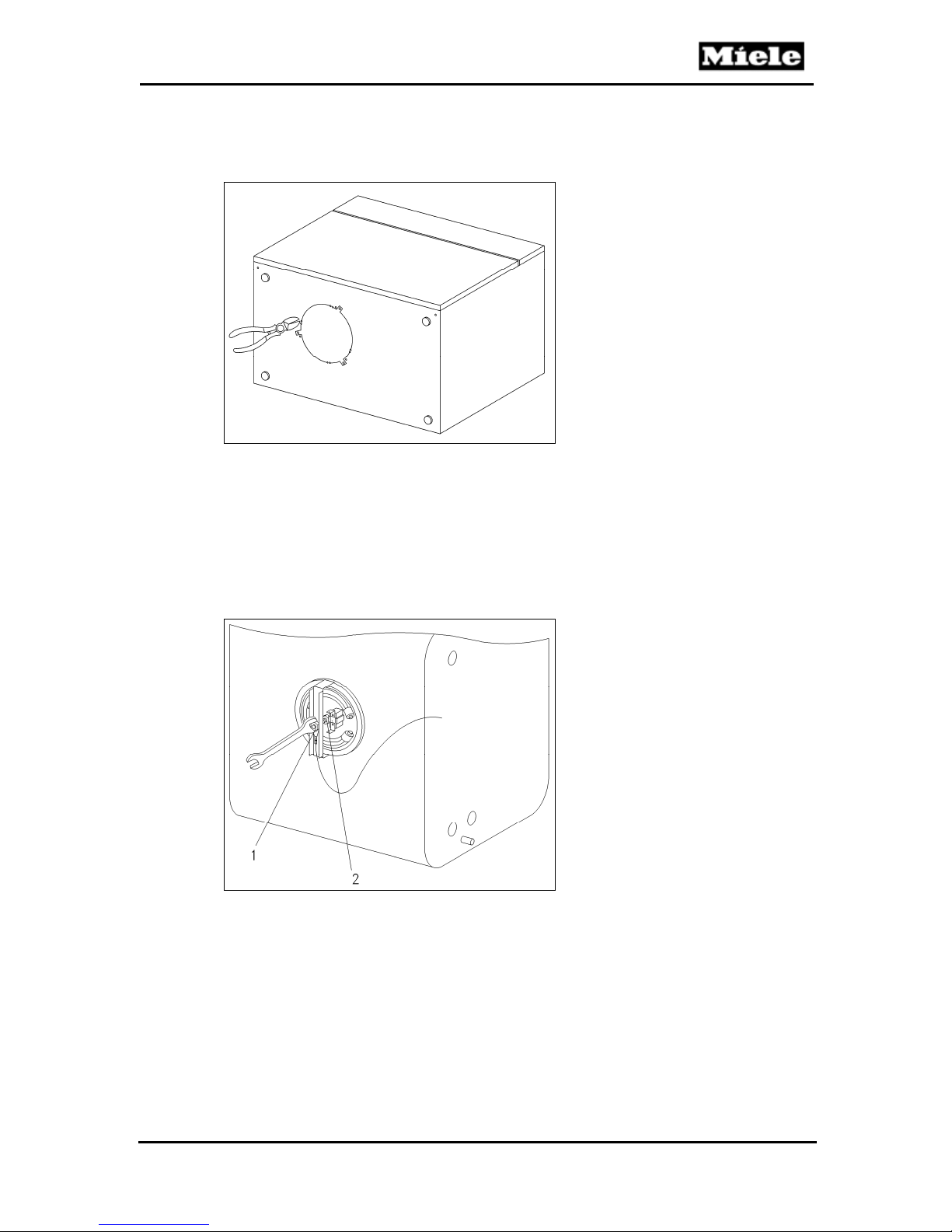
4. Use a pair of diagonal cutters to snip the lugs securing the cover to the base
(Figure 030-3). Remove the cover.
Technical Information
Figure 030-3: Floor Heater Cover
5. DG 4080: Remove the 7mm nut securing the ground wire (Figure 030-4, Item 1).
a. Disconnect the ground wire.
b. Take off the retaining clip.
c. Remove the inner 7mm retaining nut (Figure 030-4, Item 2).
d. Take off the clip and the heater assembly.
e. Disconnect all electrical connectors to the heater element.
f. Push the heater element into the oven cavity.
Figure 030-4: Floor Heater Removal (DG 4080)
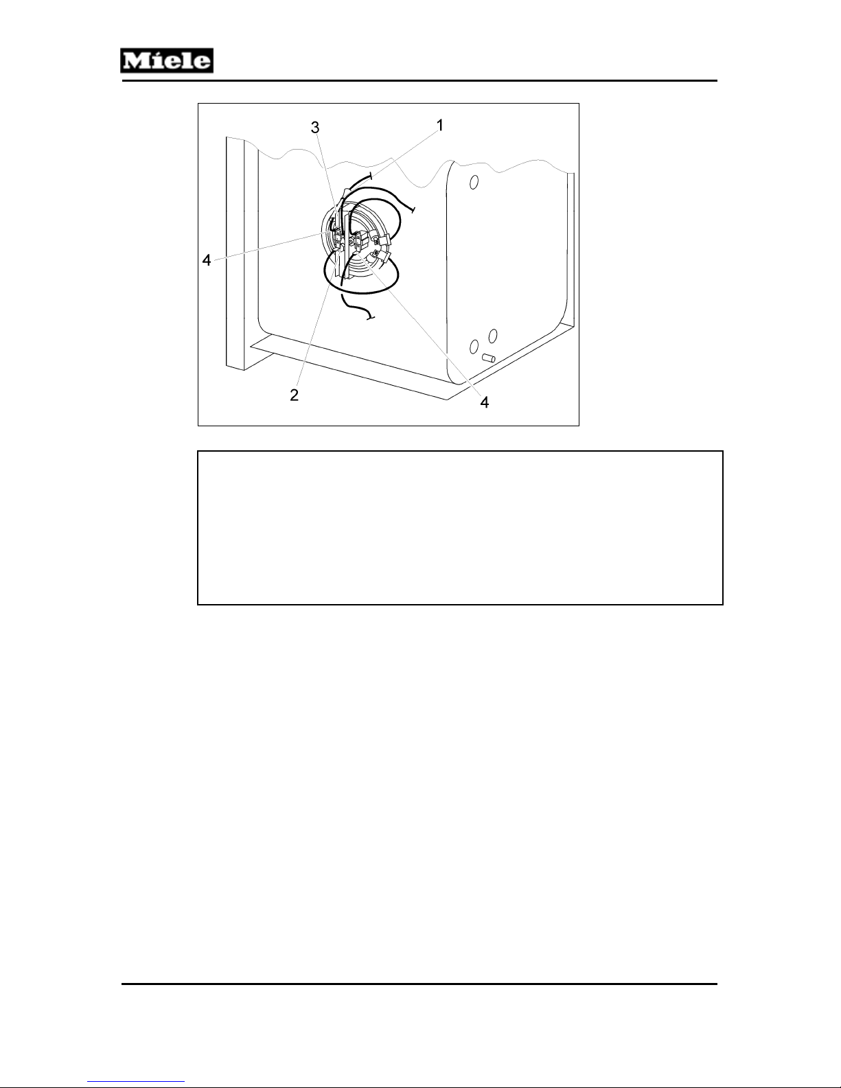
6. DG 4082: Cut the cable tie (Figure 030-5, Item 1).
a. Remove the nut securing the ground wire (Figure 030-5, Item 2).
b. Disconnect the ground wire.
c. Take off the retaining bracket (Figure 030-5, Item 3).
d. Disconnect the heater connections (Figure 030-5, Item 4).
e. Push the heater element into the oven cavity to remove.
27
Page 28
Technical Information
DG 408x Steam Ovens
Figure 030-5: Floor Heater Removal (DG 4082)
Note:
Make sure that the seal is installed properly when installing the heater
element.
When re-installing the cover, rotate it slightly (one-quarter turn) and screw
into place.
To prevent adverse operation make note of (or mark) all electrical
connections during disassembly, so they can be connected correctly during
reassembly.
4.3 Floor Heater Temperature Regulator (2F1) and Temperature
Limiter (2F8) Removal
1. Take the steam generator and equipment out of the oven cavity.
2. Uninstall the appliance. See Section 010-4.1.
3. Tip the appliance onto its back.
4. Using a pair of cutters, remove the cover from the base (Figure 030-3).
5. Remove the 7-millimeter nut securing the ground wire (Figure 030-4, Item 1).
6. Disconnect the ground wire.
7. Take off the retaining bracket.
8. Remove the retaining nut (Figure 030-4, Item 2).
9. Take off clip with temperature regulator and temperature limiter.
10. Remove connectors to temperature regulator and temperature limiter.
28
Page 29
DG 408x Steam Ovens
040 Water Tank
Technical Information
29
Page 30
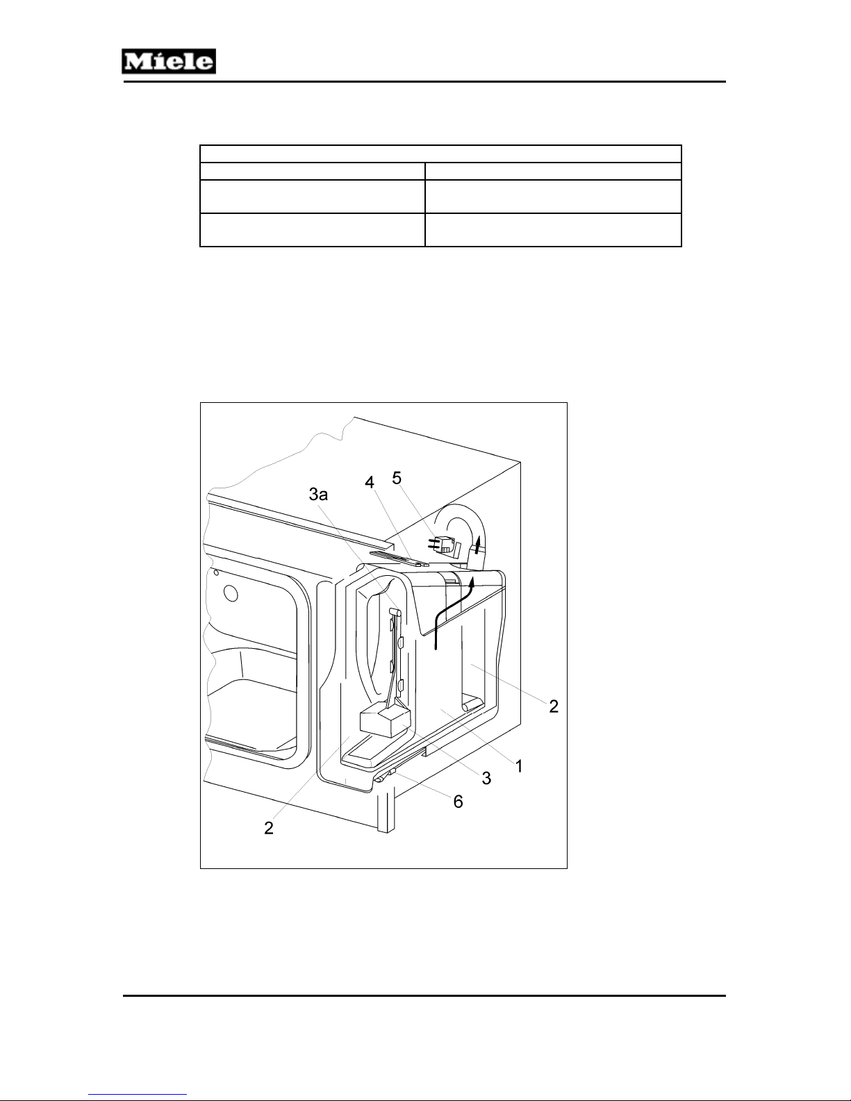
Technical Information
1 Technical Data
Steam Generator
Heater (1R25, 2R25) Output 2 x 1.1kW
Temperature Regulator (1F1)
Threshold Temperature
Temperature Limiter (1F8)
Threshold Temperature
Table 040-1: Steam Generator Data
1
Depends on distributor
2 Function
2.1 Steam Generation
DG 408x Steam Ovens
410°F (DG 4080); 410°F or 482°F (DG
1
4082)
568°F (DG 4080); 568°F or 604°F (DG
1
4082)
1 Inner chamber
2 Outer chamber
3 Float
3a Magnet
4 Water level float switch (PCB) (S12)
5 Steam generator present switch (S84)
6 Steam generator heater (1R25, 2R25)
Figure 040-1: Steam Generator
2.1.1 Construction
The insert divides the steam generator into an inner chamber (Figure 040-1,
Item 1) and an outer chamber (Figure 040-1, Item 2). Both chambers are
connected by an opening. The steam generator is equipped with dual heater
30
Page 31
DG 408x Steam Ovens
elements (1R25, 2R25), (Figure 040-1, Item 6), to heat the water in the inner
chamber. As water evaporates from the inner chamber, it is automatically
replenished with water from the outer chamber.
2.1.2 Water Level
The electronic continuously displays the water level, which is automatically
calculated by the electronic using a float (with magnet) within the steam
generator (Figure 040-1, Items 3 and 3a) and the water level float switch
(S12) (Figure 040-1, Item 4). After a pre-set heating countdown, the steam
generator heater element steam switches off and the display prompts the
user to add water.
2.1.3 Steam Generator Present Switch (S84)
The steam generator present switch registers if the steam generator is
installed in the appropriate position.
2.1.4 Heating
The steam generator can only be activated when
The steam generator switch is activated by the presence of the steam
generator (Figure 040-1, Item 5)
The water level float switch registers a sufficient quantity of water is
present within the steam generator (Figure 040-1, Item 4)
The oven door is closed.
Technical Information
During the heating-up phase, generally both heater circuits are activated.
In the maintenance phase, after the required temperature has been reached,
only one heater circuit is cycled (on/off) to maintain the oven cavity
temperature. If the temperature drops below a certain threshold, e.g., after
the oven door is opened, both heater elements may be activated.
3 Fault Repair
3.1 Appliance Does Not Heat
1. Ensure that the appliance is electrically connected to the proper supply.
2. Ensure that the appliance is NOT in the “demonstration mode”.
3. Ensure that the proper steam generator is being used. If a steam
generator from a different model number (e.g., DG 2xxx) is used it can
result in adverse operation.
3.2 Appliance Heats Too Slowly
1. Ensure that the appliance is electrically connected to the proper supply.
2. Ensure that the appliance is NOT in the “demonstration mode”.
3. Ensure that the proper steam generator is being used. If a steam
generator from a different model number (e.g., DG 2xxx) is used it can
result in adverse operation.
31
Page 32
DG 408x Steam Ovens
Technical Information
3.3 Appliance Generates Strong Steam at First Use, or After a Power
Outage/Reset
Cause:
Automatic altitude adjustment. After the first cooking process at 212°F and as part
of the descaling process, the boiling temperature is automatically adjusted to the
altitude of the location.
Remedy:
None needed.
3.4 Appliance Appears to be Incorrectly Installed
Symptom:
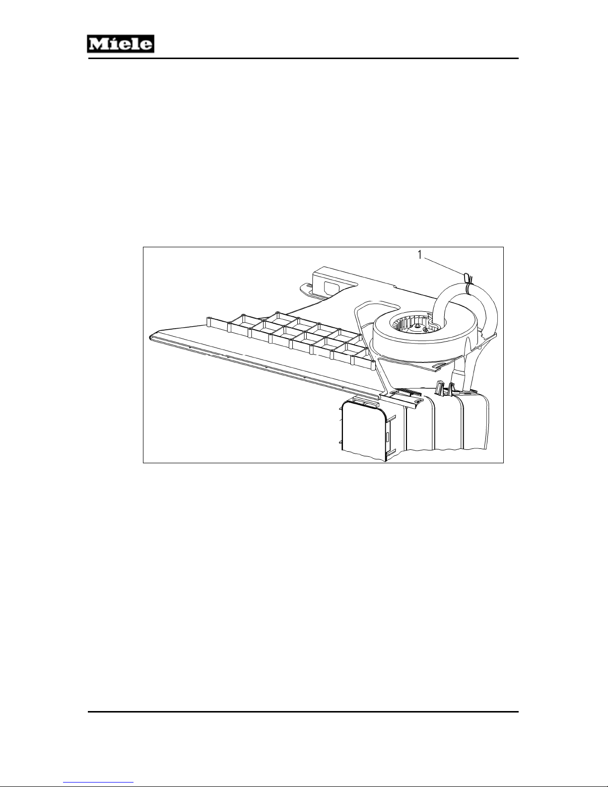
The hose clamp (Figure 040-2, Item 1) is positioned on the middle of the hose.
Figure 040-2: Hose Clamp
Cause:
No error. The hose clamp serves as kink prevention. The hose clamp prevents
kinks that get into the hose at this point, which would reduce the diameter of
the hose. The clamp is not meant to keep the hose in place.
Remedy:
None. Leave the hose clamp in its position.
3.5 Steam Generator is Discolored
Symptom:
Steam generator and insert are discolored yellow.
Cause:
Light exposure. This is only a cosmetic problem. Quality and function of the
steam generator are not diminished.
Remedy:
To avoid this, do not expose the steam generator to daylight for longer periods
of time.
32
Page 33
DG 408x Steam Ovens
Technical Information
4 Service
4.1 Checking the Resistance of the Steam Generator Heater (1R25, 2R25)
Note:
The steam generator heater consists of two heaters (240V/1100W), which
are switched in parallel.
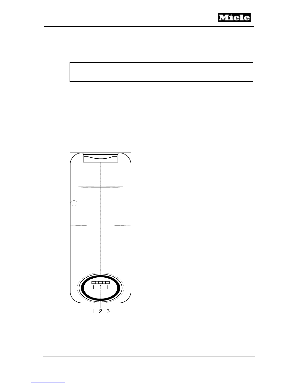
1. Heater element 1R25: Using an ohmmeter, measure the resistance
between contact points 2 and 3 (Figure 040-3). If the measured value is
approximately 100Ω, the heater element is in good condition.
2. Heater element 2R25: Using an ohmmeter, measure the resistance
between contact points 1 and 3 (Figure 040-3). If the measured value is
approximately 50Ω, the heater element is in good condition.
3. Heater elements 1R25 and 2R25: Using an ohmmeter, measure the
resistance between contact points 1 and 2 (Figure 040-3). If the
measured value is approximately 50Ω, the heater elements are in good
condition.
Figure 040-3: Steam Generator Heater Contacts
33
Page 34
DG 408x Steam Ovens
Technical Information
4.2 Removing the Steam Generator Heater (1R25, 2R25)
Note:
The heater is integrated into the steam generator housing. Should a heater
element require replacement, the steam generator must be replaced as an
assembly. The heater elements are not replaced separately.
1. Open the door.
2. Remove the steam generator.
3. Remove the insert from the steam generator housing.
4.3 Removing the Steam Generator Temperature Regulator (1F1) and
Temperature Limiter (1F8)
1. Open the door.
2. Remove the steam generator.
3. Remove the insert from the steam generator housing.
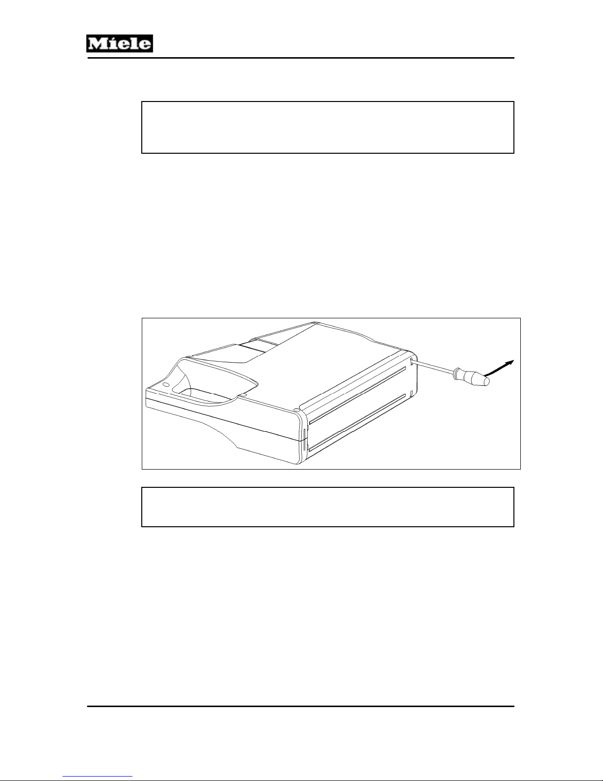
4. Remove the bottom cover from the housing by gently pulling the cover from
the assembly while using a screwdriver to release the locking tabs, as
shown in Figure 040-4.
Figure 040-4: Housing Base
Caution!
Do NOT pry the bottom cover off. It can be easily removed using the
procedure outlined above.
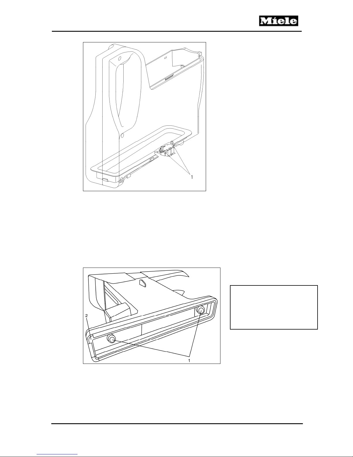
5. Remove the two T20 screws (Figure 040-5, Item 1).
6. Remove the temperature regulator and temperature limiter.
7. Disconnect all temperature regulator and temperature limiter connections.
34
Page 35
DG 408x Steam Ovens
Technical Information
Figure 040-5: Steam Generator Temperature Regulator and Temperature Limiter
4.4 Removing the Steam Duct and Seal
1. Open the door.
2. Remove the steam generator.
3. Remove the insert from the steam generator housing.
4. Remove the bottom cover from the housing by gently pulling the cover from
the assembly while using a screwdriver to release the locking tabs, as
shown in Figure 040-4.
5. Remove the two steam duct retaining screws (T10s). See Figure 040-6, Item 1.
Note:
When re-installing the seal,
make sure that the notch is
positioned as shown in
Figure 040-6, Item 2.
Figure 040-6: Steam Duct Retaining Screws
6. Remove the steam duct and seal.
35
Page 36
DG 408x Steam Ovens
Technical Information
4.5 Accessing the Tank Float/Float Switch Actuating Magnet
(DG 4080 Only)
1. Open the door.
2. Remove steam generator.
3. Remove the insert from steam generator housing.
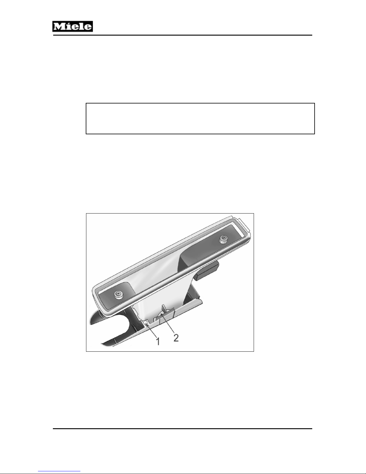
4. Remove the top cover retaining screw (Figure 040-7, Item 1).
5. Slide the top cover off to remove it from the steam duct assembly.
Note:
The two spring clips (Figure 040-7, Item 2) will release from the top cover
during removal. They will need to be re-installed into the cover prior to
reassembly.
6. Slide the float assembly upward from the track to remove.
7. Slide the new float into the track. Ensure that the float can move freely
through the track.
Reassembly:
1. Hold the top cover upside down.
2. Install and hold the top cover spring clips in position and slide the steam
duct assembly into the cover.
3. Reposition the steam duct assembly and slide it into the cover track.
4. Re-install the retaining screw (Figure 040-7, Item 1).
Figure 040-7: Removing the Top Cover from the Steam Duct Assembly
4.6 Removing the Reed Contact Float (PCB) (S12)
1. Take the steam generator and equipment out of the oven cavity.
2. Uninstall the appliance. See Section 010-4.1.
3. Remove the right side panel. See Section 010-4.2.
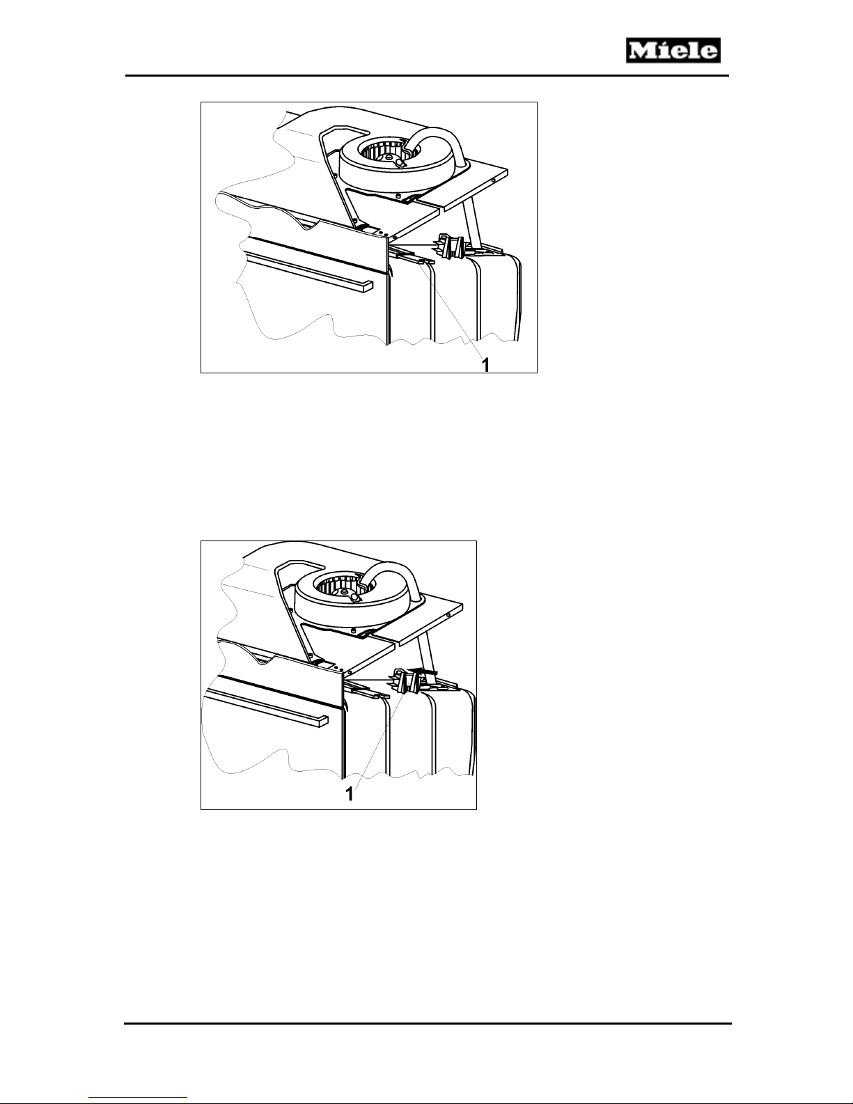
4. Disconnect the connection from the float PCB (Figure 040-8, Item 1).
5. Remove the PCB with a pair of pliers.
36
Page 37
DG 408x Steam Ovens
Technical Information
Figure 040-8: Reed Contact Float
4.7 Removing the Steam Generator Present Switch (S84)
1. Take the steam generator and equipment out of the oven cavity.
2. Uninstall the appliance. See Section 010-4.1.
3. Remove the right side panel. See Section 010-4.2.
4. Pull the retaining tabs back to access the switch (Figure 040-9, Item 1)
and slide the switch out.
5. Disconnect all switch connections.
Figure 040-9: Steam Generator Present Switch
4.8 Removing the Steam Generator Socket
1. Take the steam generator and equipment out of the oven cavity.
2. Uninstall the appliance. See Section 010-4.1.
3. Remove the right side panel. See Section 010-4.2.
4. Remove the retaining plate from the socket.
5. Release the socket tabs.
6. Remove the socket via the rear of the appliance.
37
Page 38
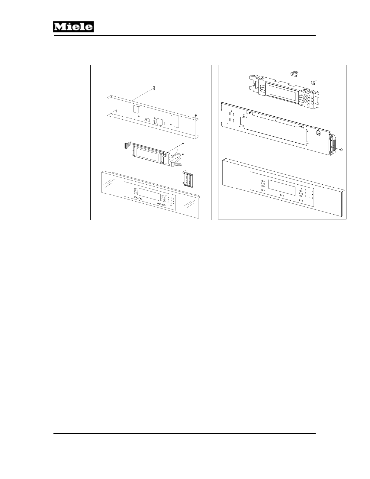
Technical Information
060 Fascia, Electronics
DG 408x Steam Ovens
DG 4080 DG 4082
38
Page 39
DG 408x Steam Ovens
2 Function
2.1 Optical Interface
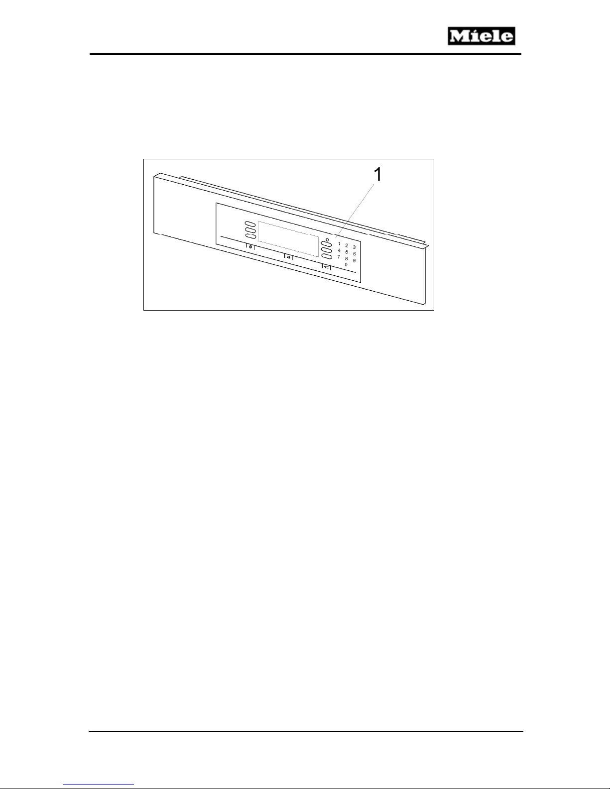
The appliance has an optical interface to support diagnosis. See Figure 0601, Item 1. The interface can be located with the “Find Optical Interface”
function of the Miele diagnostic support (MDU).
Technical Information
Figure 060-1 Optical Interface
39
Page 40
Technical Information
2.2 Electronics Overview
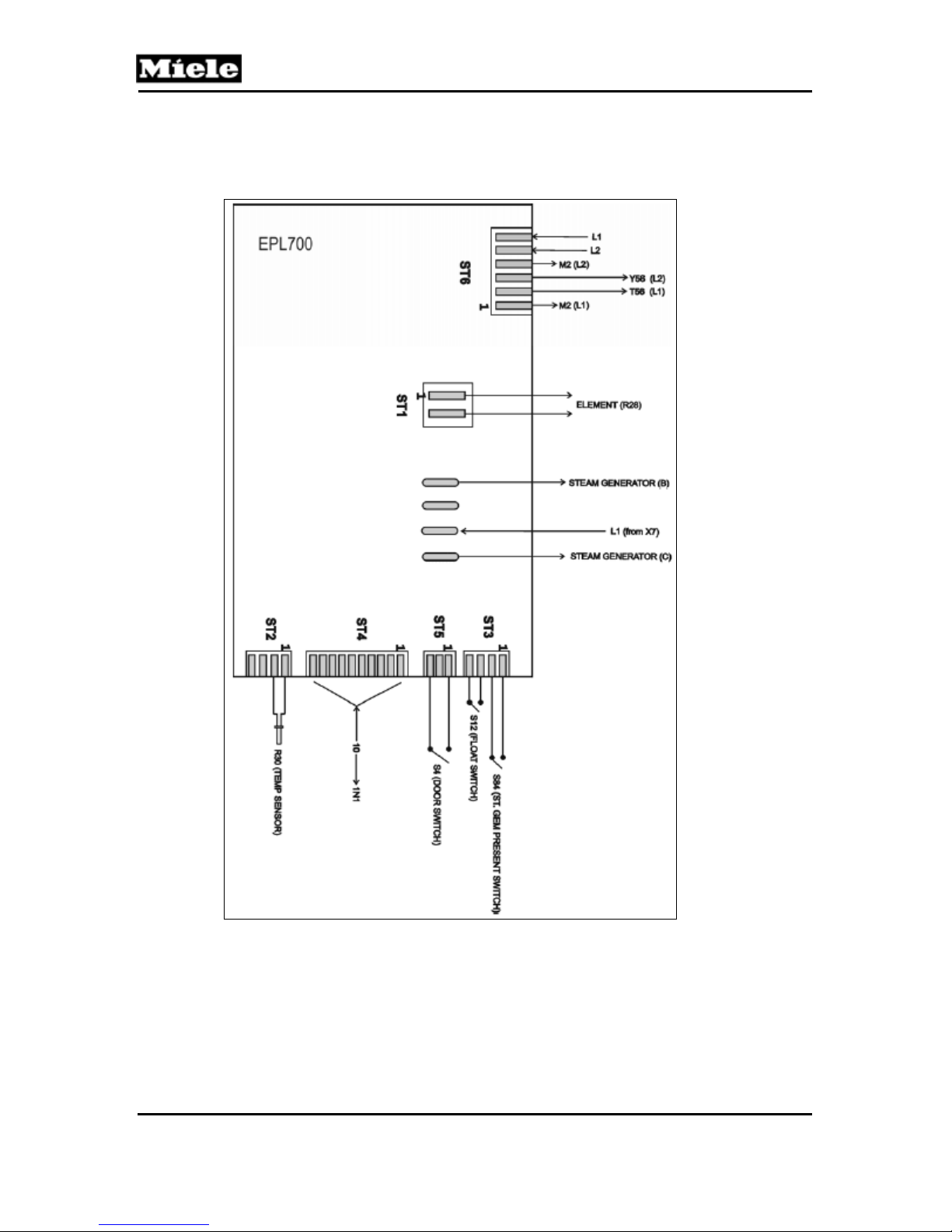
2.2.1 Main Electronic
DG 408x Steam Ovens
Figure 060-2: EPL700 Electronic – Overview (DG 4080 Shown)
40
Page 41
DG 408x Steam Ovens
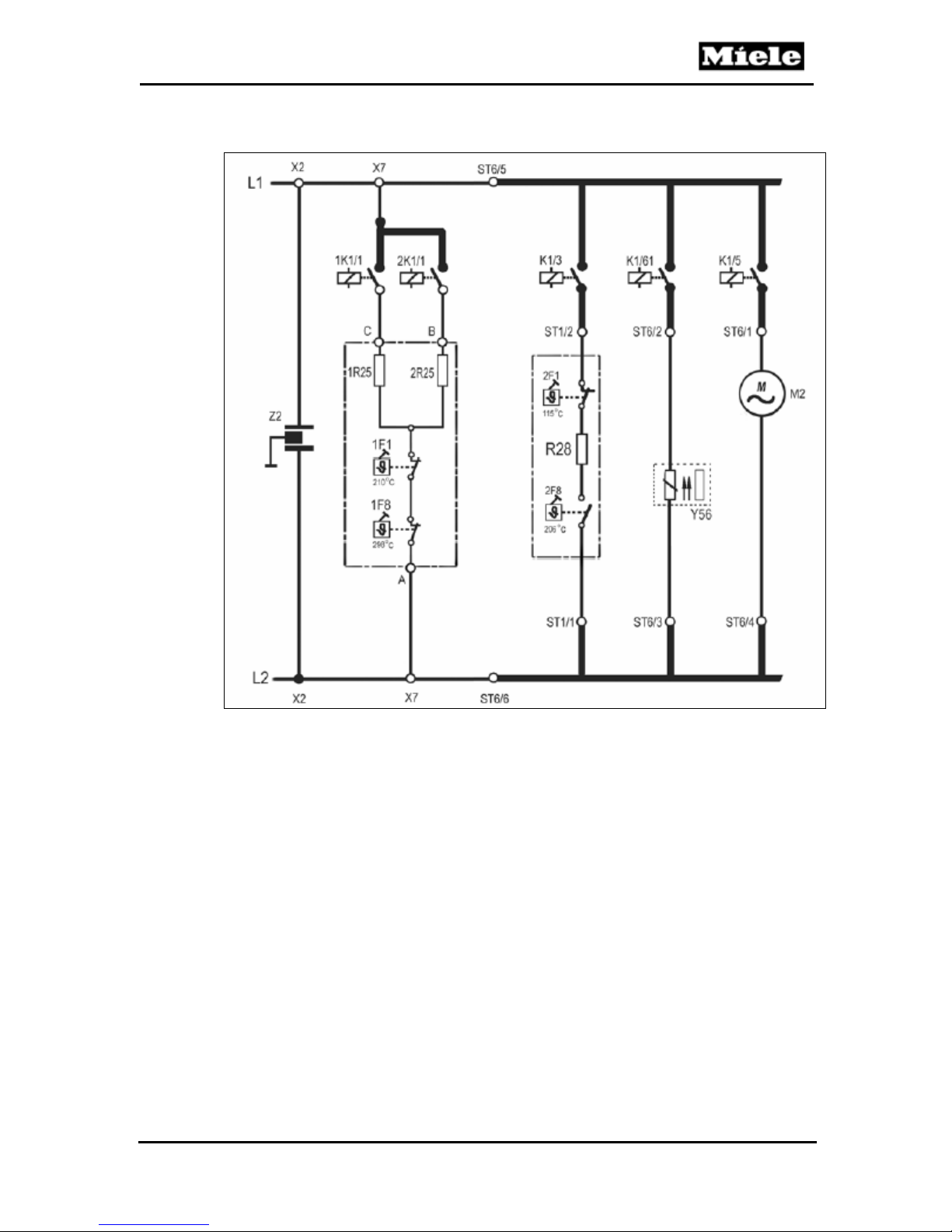
2.2.2 AC Power Electrical Circuit
Technical Information
Figure 060-3: AC Power Electrical Circuit (DG 4080)
2.3 Warming Function
If the appliance is not switched off after a cooking process, foods can be kept
warm at 158°F for a maximum of 15 minutes. In this case the display shows
“Warming”. This function can be set in customer programming. Warming is
cancelled automatically when the door is opened. The factory setting is “Off”
for DG 4080 and “On” for DG 4082.
2.4 Power Management
Starting with ID795, the electronic is equipped with a power management
feature. If this feature is enabled, the oven floor heater will not be activated
during the heating-up phase and only one steam generator element will be
used during operation. The factory setting is “Off”.
2.5 Descaling
Descaling agent is added to the water (see the operating manual for
instructions).
1-minute exposure phase: In this phase the process can still be aborted
without subsequent “forced descaling”.
41
Page 42
DG 408x Steam Ovens
Technical Information
11-minute descaling phase: The un-calibrated appliance is heated to
194°F (90°C); the calibrated appliance, 203°F (95°C).
Rinse and refill with fresh water.
10-minute calibration phase: The boiling temperature is adjusted for the
altitude of the location.
See the operating manual for the descale procedure.
3 Fault Repair
3.1 Fault Code Summary
Fault Code Description of Fault Cause and Remedy
F05
F06
F20
F44 (newer DG 4080s,
DG 4082)
Table 060-1: Fault Codes
Short circuit in PT 1000
temperature sensor
Open circuit in PT 1000
temperature sensor
Heating fault See Section 060-3.4.
Faulty control electronic/
power electronic interface
3.2 F05 - Short Circuit in PT 1000 Temperature Sensor
See Section 060-3.2.
See Section 060-3.3.
See Section 060-3.5.
Cause:
PT 1000 temperature sensor (R30) or connector short-circuited.
Remedy:
Replace the temperature sensor. See Section 030-4.1.
3.3 F06 - Open Circuit in PT 1000 Temperature Sensor
Cause:
PT 1000 temperature sensor (R30) or connector open-circuited.
Remedy:
Replace the temperature sensor. See Section 030-4.1.
Cause:
Electronic not plugged in or poor plug contact.
Remedy:
1. Check plug for correct position and contact.
2. Insert plug properly.
3. If plug is defective, replace the temperature sensor. See Section 030-4.1.
.
3.4 F20 - Heating Fault
Symptom:
Fault code F20 shows up if no temperature increase is registered within 5
minutes. If the appliance is in a preheated state, this time is reduced to 3
minutes. After a new start, fault code F20 no longer shows up. It only appears
again if a new fault occurs.
42
Page 43
DG 408x Steam Ovens
Cause:
Steam generator not seated correctly or seal not sufficiently lubricated.
Remedy:
Lubricate the seal with silicone grease (part no. 05132001).
Slide the steam generator in properly, over the guides in the floor of the
housing.
Cause:
Steam generator heater (1R25, 2R25) defective.
Remedy:
Test the steam generator in service mode; refer to Section 060-4.2.
Note:
The heater elements are integrated into the housing of the steam generator
and cannot be replaced separately. Replace the entire steam generator
assembly if either of these heater elements is defective.
Cause:
Temperature sensor does not register the increase in temperature.
Remedy:
Check if the temperature sensor is seated in its seal. Re-fit it, if necessary.
Technical Information
Cause:
Water being used is extremely cold.
Remedy:
Use water at room temperature.
Cause:
Heavy mineral deposits.
Remedy:
Descale appliance. See the operating instructions.
Cause:
Float for monitoring water level is jammed. Safety cutoff after 38 minutes’
straight heating time.
Remedy:
Check float and guide at the insulated part of the steam generator.
Replace float or steam generator insulation, if necessary.
Cause:
Problems with the contact of the steam generator socket.
Remedy:
Replace the steam generator and its 3-pin socket; see Section 040-4.7.
Cause:
Software fault. At an altitude higher than 2183 feet (2000 meters) above sea
level, the descaling process is aborted. F20 appears in the display.
Remedy:
Since production index 41/..., a UBS altitude adjustment package (mat. no.
08349700) has been used. The UBS contains the electronics mat. nos.
06054305 and 06427543. After installing this UBS, the oven will have the
preheat function.
43
Page 44
DG 408x Steam Ovens
Technical Information
3.5 F44 - Control Electronic/Power Electronic Interface is Faulty
Symptom:
Faulty communication between control electronic and power electronic.
Cause:
Defective connectors or plugs between the electronics.
Remedy:
Check connectors and plugs. Replace as necessary.
Cause:
Defective control electronic.
Remedy:
Replace the control electronic. See Section 060-4.4.
Cause:
Defective power electronic.
Remedy:
Replace the power electronic.
3.6 Displays Look Different
Symptom:
The displays of different appliances with Navitronic controls (H 4000, H 4000
BM, DG 4000) have a different appearance.
Cause:
Different angles of view (units next to each other, or one above the other),
different light reflection.
Remedy:
Use the “Brightness” and “Contrast” functions to adjust the displays; see
Section 060-4.1.
3.7 Wrong Language Setting
Cause:
Several languages are available.
Remedy:
Use the language icon
as a guide to set the desired language.
3.8 Display Dims
Cause:
The time of day indication can be programmed.
Remedy:
See Section 060-4.1.
3.9 Time of Day Shown in 12-Hour Format/24-Hour Format
Cause:
The time format can be programmed.
Remedy:
See Section 060-4.1.
44
Page 45
DG 408x Steam Ovens
3.10 Cooking Program Does Not Start
Cause:
Start is set to “manual”.
Start can be set as manual or automatic. If start was set to “manual”, then the
start of a cooking cycle has to be confirmed manually.
Remedy:
Set start to “automatic”; refer to Section 060-4.1.
3.11 Excessive Steam in the Oven Cavity
Cause:
Steam reduction has been shut off.
Remedy:
Turn on steam reduction; refer to Section 060-4.1.
3.12 Cooked Food Is Not Kept Warm
Cause:
Warming function has been shut off.
Remedy:
Turn on the warming function; refer to Section 060-4.1.
Technical Information
Cause:
Steam reduction has been shut off. Warming is not possible while steam
reduction is shut off.
Remedy:
Turn on steam reduction; refer to Section 060-4.1.
Check if warming is turned on; see Section 060-4.1.
3.13 Recommended Temperatures Are Changed
Cause:
Recommended temperatures can be programmed.
Remedy:
See Section 060-4.1.
3.14 Display Is Hard To Read
Cause:
Display brightness and contrast can be set.
Remedy:
See Section 060-4.1.
3.15 Buzzer at the End of a Cooking Cycle is Too Loud/Soft/Short
Cause:
The melody, volume and duration of the buzzer tone can be set.
Remedy:
See Section 060-4.1.
45
Page 46
DG 408x Steam Ovens
Technical Information
3.16 When Touching a Keypad, Tone is Too Loud or Too Soft
Cause:
Keypad volume can be programmed. The keypad tone can also be turned on or off.
Remedy:
See Section 060-4.1.
3.17 System Lock Is Possible/Not Possible
Symptom:
The lock icon is not present in the display.
Cause:
To accept or not to accept the system lock can be programmed.
Remedy:
See Section 060-4.1.
3.18 Temperature in °C / °F
Cause:
The temperature format can be programmed.
Remedy:
See Section 060-4.1.
4 Service
4.1 Programming Mode
Initial requirements:
Shut off the appliance.
Accessing:
Note:
Access has to be completed with 10 seconds.
1. Touch and hold the Timer pad for DG 4082, or the Clear pad for DG 4080.
2. Touch and hold the On pad.
3. Release the Timer (Clear) and On pads at the same time.
4. Touch the Timer (Clear) pad five times and hold on the fifth time until the
programming mode appears.
Acknowledgement indicator:
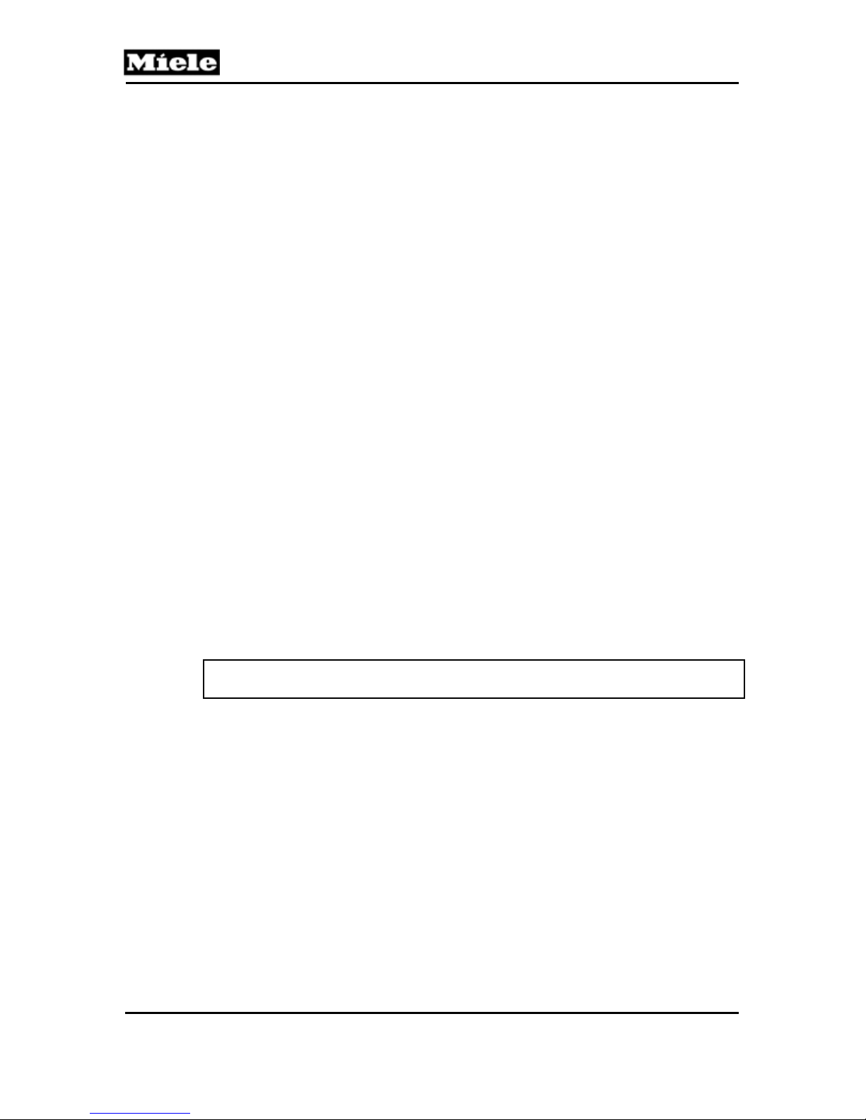
The display shows the programming options.
LANGUAGE TEMPERATURE
CLOCK WATER HARDNESS
TEMPERATURES More
Options:
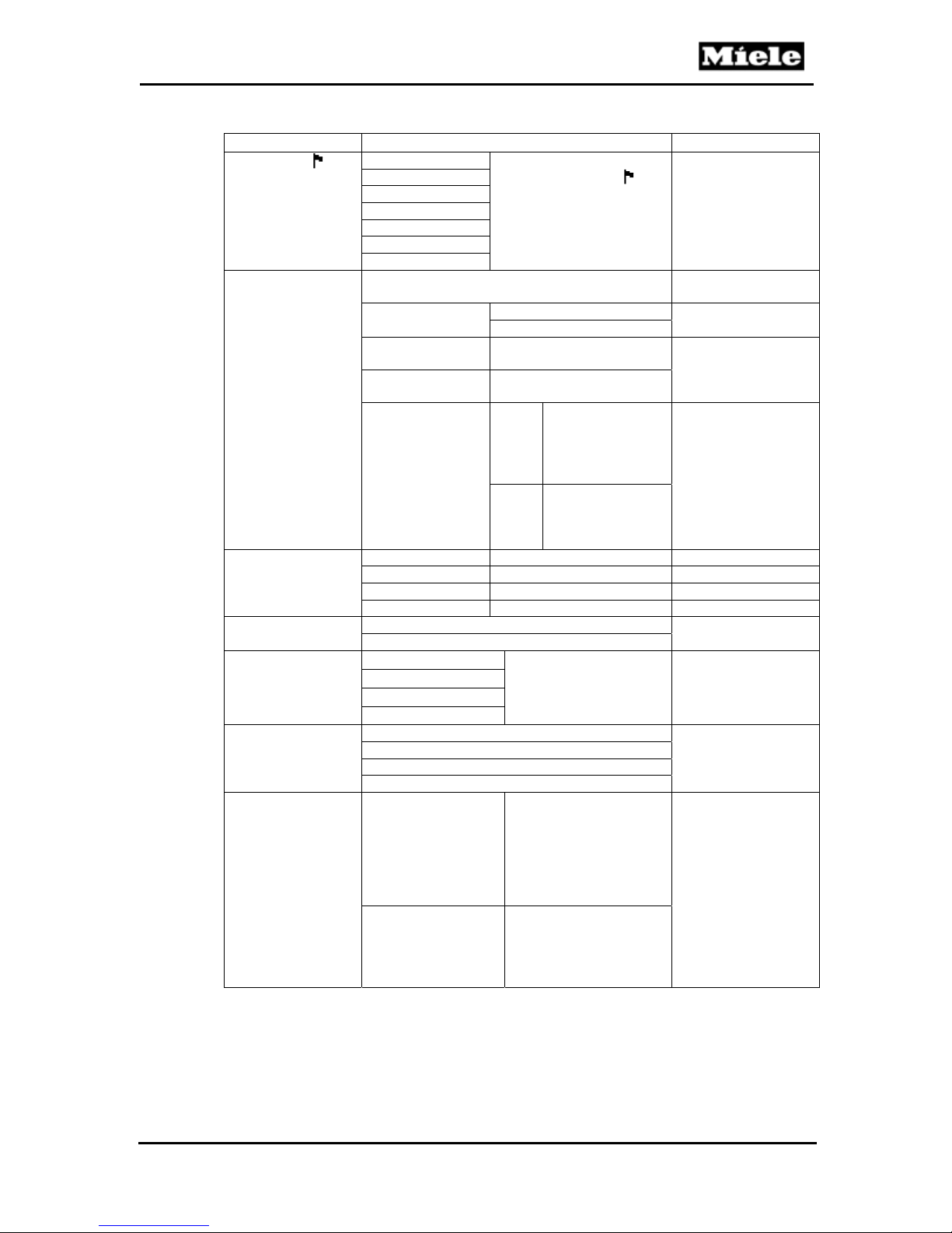
Touch the pad next to the desired option (refer to Table 060-2). Press Timer
(Clear) to go back one level.
Touch the pad next to the desired setting (refer to Table 060-2). Press Timer
(Clear) to go back one level.
46
Page 47
DG 408x Steam Ovens
K
1
Option Available Settings Factory Setting
LANGUAGE1
CLOC
RECOMMENDED
TEMP. or
TEMPERATURES1
TEMPERATURE1
WATER
HARDNESS
(DG 4080 only)
WATER
HARDNESS
(DG 4082 only)
STEAM
REDUCTION
Technical Information
deutsch If the language setting is
english
espanol
francais
italiano
polski
português
1
1
1
The time of day can be entered using the
numeric keypad.
Size Normal Normal
12-hour clock The time of day is shown
24-hour clock The time of day is shown
Clock display On The time of day
CUSTOM 105°F - 212°F 212°F
CANNING 175°F - 212°F 212°F
REHEAT 175°F - 212°F 212°F
DEFROST 125°F - 140°F 140°F
°F °F
°C
Level 1 (# - # ppm) Touch pad next to
Level 2 (# - # ppm)
Level 3 (# - # ppm)
Level 4 (# - # ppm)
Level 4 Level 8
Level 8
Level 12
Level 16
On Shortly before the
Off Steam reduction is shut
incorrect, follow the
icon to locate the
language menu.
Large
in 12-hour format.
in 24-hour format.
will be shown in
the display when
the appliance is
shut off.
Off When the
appliance is shut
off, the display
remains dark.
Softer or Harder until
the desired level is
indicated.
cooking time is up, the
release element opens
the door a crack to
reduce steam in the
oven cavity; see
Section 010-2.4.
off. When steam
reduction is shut off, the
warming option cannot
be used.
english
--
12-hour format
On
Level 4
On
47
Page 48
K
1
DG 408x Steam Ovens
Technical Information
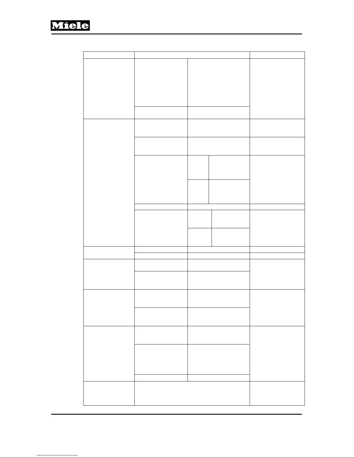
Option Available Settings Factory Setting
WARMING
FUNCTION
BUZZER or TONE
OPTIONS
DISPLAY1
START
SETTINGS
SYSTEM LOC
RESET1
RESET ALL
1
1
1
On If the appliance is not
shut off after a cooking
process, foods can be
kept warm at 158°F for
a maximum of 15
minutes. In this case
the display reads,
“Warming.”
Off The warming function is
shut off.
Minute
Minder/Timer 1
Tone
Minute
Minder/Timer 2
Tone
Keypad Tone On When a pad is
Volume 1 - 5 5
Tone Short The buzzer
Brightness 1 - 5 4
Contrast 1 - 5 4
Automatic start The cooking cycle starts
Manual start The cooking cycle has
Accept The appliance can be
Do not accept The appliance cannot
TEMPERATURES Only the recommended
SETTINGS
(DG 4082 only)
FAVORITES All favorites are deleted.
All settings made by the customer are reset to
factory settings when Yes is pressed.
Favorites are erased. The fault memory
remains.
1 - 5 1
1 - 5 1
touched, a
tone is
emitted.
Off When a pad is
touched, no
tone is
emitted.
sounds three
times.
Long The buzzer
sounds for 1
hour.
automatically.
to be confirmed
manually.
safeguarded against
accidental operation.
be safeguarded against
accidental operation.
temperatures revert to
factory settings.
All settings made by the
customer revert to
factory settings, except
for favorites and the
fault memory.
Off for DG 4080; on
for DG 4082
On
Short
Automatic start
Do not accept
--
--
48
Page 49
DG 408x Steam Ovens
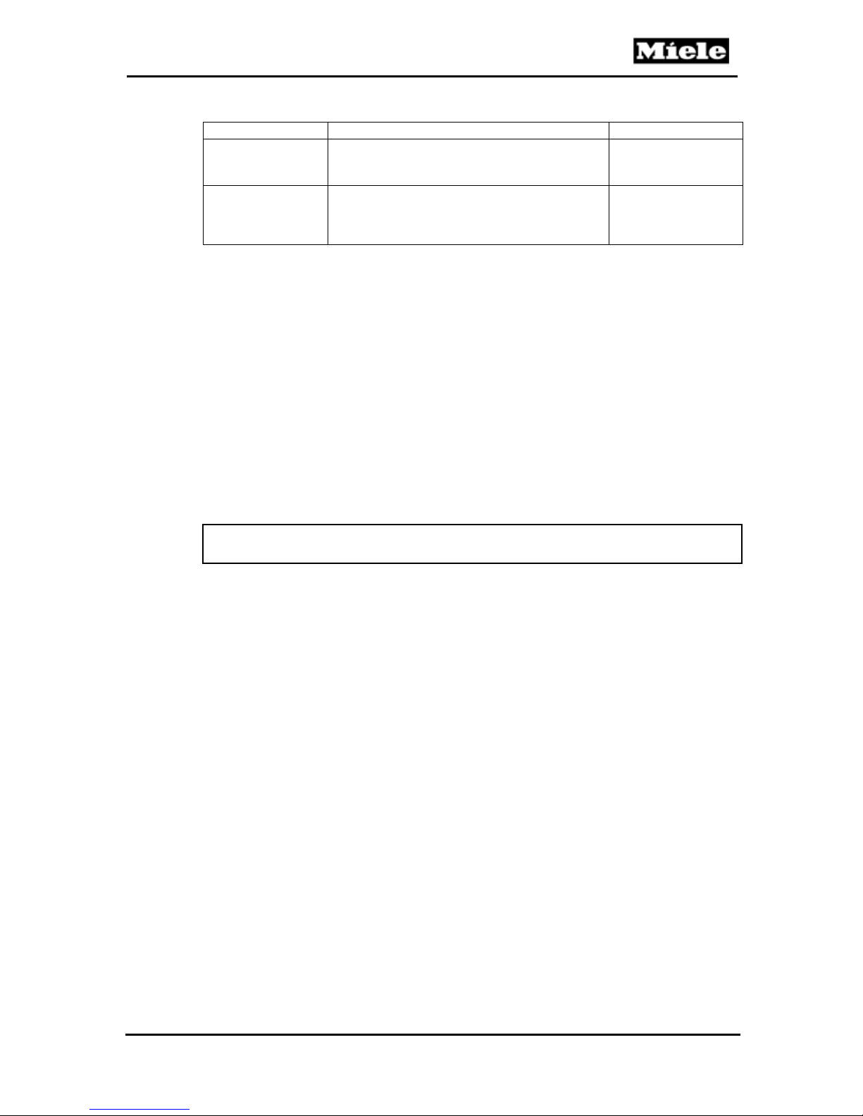
Option Available Settings Factory Setting
RESTART or NEW
START
RESET
DESCALING or
DESCALE CLEAR
2
Table 060-2: Programming Mode
1
These settings can also be changed in customer programming.
2
“Descaling” is only visible when the descaling lock is active. In order to activate the
descaling lock, start the descaling process, let it run for more than one minute and then
interrupt the program.
Back (without saving): Touch the Timer (Clear) pad.
Save and back: Touch the pad next to OK.
Quit: Touch the Off pad.
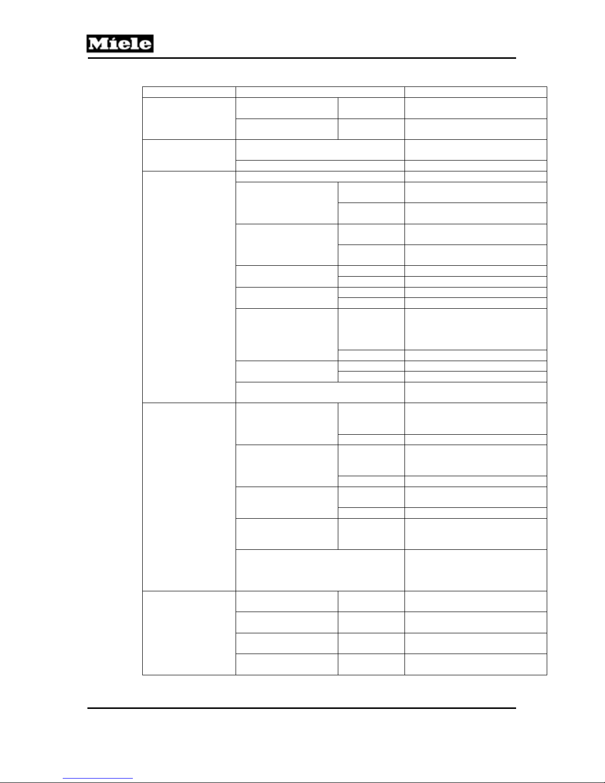
4.2 Service Mode
Initial requirements:
Shut off the appliance.
A restart is like a power disconnection. All
settings made by the customer, as well as
favorites and the fault memory, remain.
The descaling lock is cleared. Warning! After
service is completed, the appliance has to
be descaled.
Technical Information
--
--
Accessing:
Note:
Access must be completed with 10 seconds.
1. Touch and hold the Timer pad for DG 4082, or the Clear pad for DG 4080.
2. Touch and hold the On pad.
3. Release the Timer (Clear) and On pads at the same time.
4. Touch the Timer (Clear) pad three times and hold on the third time until the
service mode appears.
Acknowledgement indicator:
The display shows the service options.
INDEX SENSOR TEST
FAULT INDEX RUNNING TIME
FUNCTION TEST More
Options:
Touch the pad next to the desired option (see Table 060-3). Press Timer
(Clear) to go back one level.
Touch the pad next to the desired setting (see Table 060-3). Press Timer
(Clear) to go back one level.
49
Page 50
Technical Information
Option Setting/Activation Description
INDEX
FAULT INDEX
FUNCTION TEST
SENSOR TEST
RUNNING TIME
Table 060-3: Service Mode
DG 408x Steam Ovens
CONTROL
ELECTRONIC
POWER
ELECTRONIC
“No Faults” or fault code, e.g., “F 01” All faults registered so far are
Delete faults All saved faults are deleted.
ALL OFF All components are switched off.
HEATING CIRCUIT 1/
STEAM GENERATOR
(1R25)
HEATING CIRCUIT 2/
STEAM GENERATOR
(2R25)
LOWER HEAT ELEM.
or FLOOR HEATER
FAN (M2) On The fan (M2) is switched on.
DOOR OPENER (Y56) On The release element (Y56) is
BUZZER On The buzzer sounds.
DISPLAY The display alternately lights up
STEAM GENERATOR
CONTACT or STEAM
GENERATOR
CONTROL
LEVEL INDICATOR or
FILL INDICATOR
DOOR SWITCH Closed Door is closed. Door contact
TEMP INTERIOR e.g., 81°F The temperature at the PT 1000
KEYPAD or FUNCTION PAD PANEL All keypads, with the exception of
HEATING CIRCUIT 1 e.g., 0008h The operating hours of heater
HEATING CIRCUIT 2 e.g., 0008h The operating hours of heater
LOWER HEAT ELEM.
or FLOOR HEATER
DESCALE or NO. OF
DESCALES
e.g., EPX 702
ID33795 V.2
e.g., EPL 700
ID00796
On Steam generator heater (1R25)
Off Steam generator heater (1R25)
On Steam generator heater (2R25)
Off Steam generator heater (2R25)
On Floor heater R28 is switched on.
Off Floor heater R28 is switched off.
Off The fan (M2) is switched off.
Off The door closes again slowly.
Off The buzzer goes silent.
Closed Steam generator is inserted. The
Open Steam generator is not inserted.
Closed The steam generator is filled.
Open The steam generator is not filled.
Open The door is open.
e.g., 0005h The operating hours of heater
e.g., 1 The number of descales
The ID number of the control
electronic (2N1) is indicated.
The ID number of the power
electronic (3N1) is indicated.
indicated; refer to Table 060-1.
is switched on.
is switched off.
is switched on.
is switched off.
activated and controls the door
opener via a metal rod, which
opens the door a crack.
and goes dark.
steam generator switch (S84) is
switched on.
The level switch (S12) is
switched on.
switch (S4) is switched on.
temperature sensor (R30) is
indicated. (F06 if open circuited.)
“Timer” and “Off” (DG 4082) or
“Clear” and “Off” (DG 4080), can
be checked by touch.
1R25 are indicated.
2R25 are indicated.
R28 are indicated.
performed is indicated.
50
Page 51
DG 408x Steam Ovens
Back: Touch the Timer (Clear) pad.
Save: Touch the Off pad.
4.3 Removing the Fascia Panel Assembly
4.3.1 DG 4080
1. Take the steam generator and equipment out of the oven cavity.
2. Uninstall the appliance. See Section 010-4.1.
3. Remove both side covers. See Section 010-4.2.
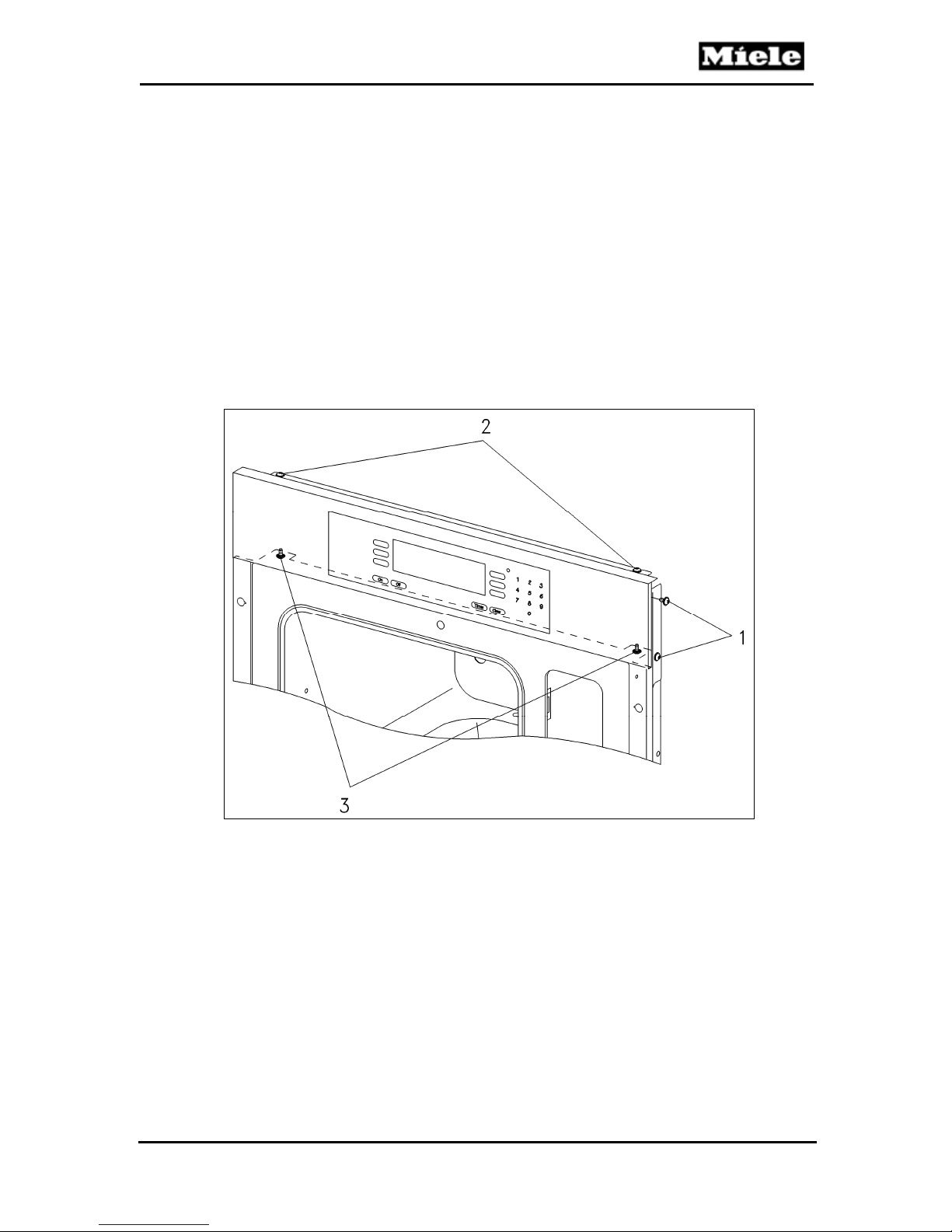
4. Remove screws of fascia panel (Figure 060-4, Item 1, left and right).
5. Disconnect wiring and ground lead.
6. Take off fascia panel with support plate.
7. Remove screws from support plate (Figure 060-4, Items 2 and 3).
8. Separate fascia panel from support plate.
Technical Information
Figure 060-4: Fascia Panel Assembly (DG 4080)
9. Disconnect connections from the control and display electronics.
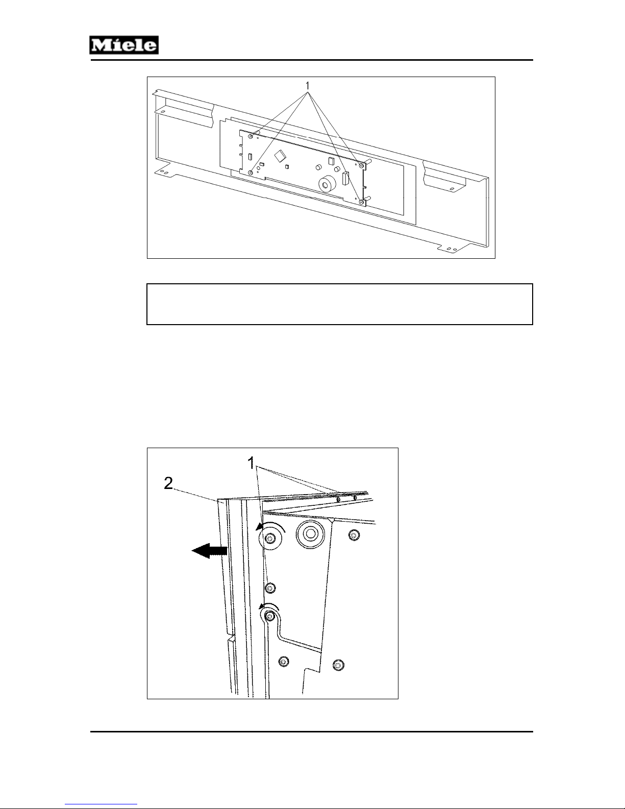
10. Remove screws (Figure 060-5, Item 1).
11. Take off the control electronic.
51
Page 52
Technical Information
DG 408x Steam Ovens
Figure 060-5: Control Electronic Screws (DG 4080)
Note:
The fascia panel is firmly attached to the display electronic and can only be
replaced together as an assembly.
4.3.2 DG 4082
1. Take the steam generator and equipment out of the oven cavity.
2. Uninstall the appliance. See Section 010-4.1.
3. Remove the four T20 screws securing the fascia panel (Figure 060-6,
Item 1, left and right).
4. Loosen the four T20 screws securing the control electronic mounting
bracket to the fascia panel (see arrows, Figure 060-6, left and right).
5. Remove the fascia panel partway (Figure 060-6, Item 2).
Figure 060-6: Fascia Panel (DG 4082)
52
Page 53
DG 408x Steam Ovens
6. Disconnect the ribbon cable connecting the selection electronic to the
control electronic.
7. Take off the fascia panel.
Note:
The fascia panel is firmly attached to the selection electronic and can only
be replaced as a complete assembly.
4.4 Removing the Control Electronic (DG 4082)
1. Uninstall the appliance. See Section 010-4.1.
2. Remove the fascia panel. See Section 060-4.4.
3. Disconnect all control electronic connections (two wiring harnesses and
one ground wire).
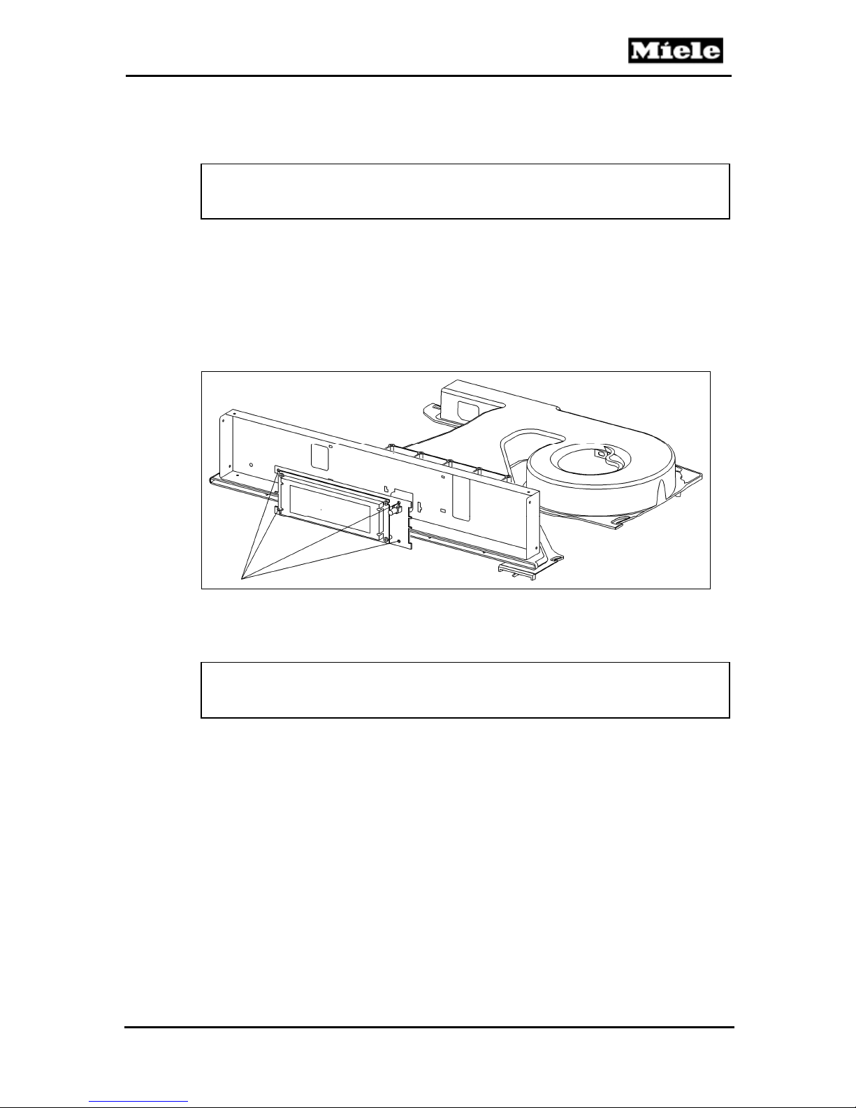
4. Unclip and remove the control electronic from its mounting bracket. See
Figure 060-7.
Technical Information
Figure 060-7: Removing the Control Electronic (DG 4082)
4.5 Removing the Selection Electronic
Note:
The fascia panel is firmly attached to the selection electronic and can only
be replaced as a complete assembly.
1. Remove the fascia panel. See Section 060-4.3.
2. Install a new fascia panel/selection electronic assembly.
53
Page 54
DG 408x Steam Ovens
Technical Information
070 Technical Service Bulletins
1
Position Setting / Activation Description / Result
DG 4080 Steam Oven Displays F20 in a New Installation
When a DG 4080 displays F20 (heating fault), there are several possible
causes outlined in the service documentation.
If you should encounter a new steam oven with persistent F20 problems,
please ascertain that the unit is properly connected to 240 volts. If the steam
oven is connected to 120 volts, the electronic will still operate and show a
display, but the steam generator will never properly heat up.
The absolute confirmation for this problem is to remove the unit and measure
the voltage at the outlet.
PROGRAM
INDEX
FAULT
MEMORY
FUNCTION
TEST
FUNCTION
TEST
FUNCTION
TEST
CONTROL
ELECTRONIC
OUTPUT
ELECTRONIC
e. g. Fault 01
Delete faults All saved faults are deleted.
HEATING
CIRCUIT 1
HEATING
CIRCUIT 2
FLOOR HEATER
e.g. EPX 702
ID33795 V.2
e. g. EPL
700 ID00796
On
Off
On
Off
On
Off
The ID number of the Control
Electronic (2N1) is indicated.
The ID number of the Output
Electronic (3N1) is indicated.
All faults registered so far are
indicated.
The steam generator heater (1R25) is
switched on.
The steam generator heater (1R25) is
switched off.
The steam generator heater (2R25) is
switched on.
The steam generator heater (2R25) is
switched off.
The floor heater element (R28) is
switched on.
The floor heater element (R28) is
switched off.
FUNCTION
TEST
FUNCTION
TEST
FUNCTION BUZZER On The buzzer sounds.
FAN (M2)
DOOR OPENER
(Y56)
On The fan motor (M2) is switched on.
Off The fan motor (M2) is switched off.
The release element (Y56) is activated
On
Off The door closes again slowly.
and controls the door opener via a
metal rod, which opens the door a
crack.
54
Page 55
DG 408x Steam Ovens
T
Technical Information
Position Setting / Activation Description / Result
TEST Off The buzzer goes silent.
FUNCTION
TEST
SENSOR
TEST
SENSOR
TEST
SENSOR
TEST
SENSOR
TEST
SENSOR
TEST
DISPLAY
STEAM
GENERATOR
CONTROL
FILL INDICATOR
DOOR SWITCH
PT 1000 OVEN
CAVITY
FUNCTION PAD PANEL
HEATING
CIRCUIT 1
Closed
Open The steam generator is not inserted.
Closed
Open The steam generator is not filled.
Closed
Open The door is open.
e. g. 81 °F
e. g. 0008h
The display alternately lights up and
goes dark.
The steam generator is inserted. The
steam generator switch (S84) is
switched on.
The steam generator is filled. The reed
contact float (S12) is switched on.
The door is closed. The door contact
switch (S4) is switched on.
The temperature at temperature
sensor PT 1000 (R30) is indicated.
All function pads, with the exception of
“Clear” and “Off”, can be checked by
touch.
The operating hours of the steam
generator heater (1R25) are indicated.
RUNNING
TIME
HEATING
CIRCUIT 2
FLOOR HEATER e. g. 0005h
DESCALE e. g. 1
e. g. 0008h
The operating hours of the steam
generator heater (2R25) are indicated.
he operating hours of the floor heater
element (R28) are indicated.
The number of descales performed is
indicated.
55
 Loading...