

Page 1
Product Dimensions Page 1 o f 7
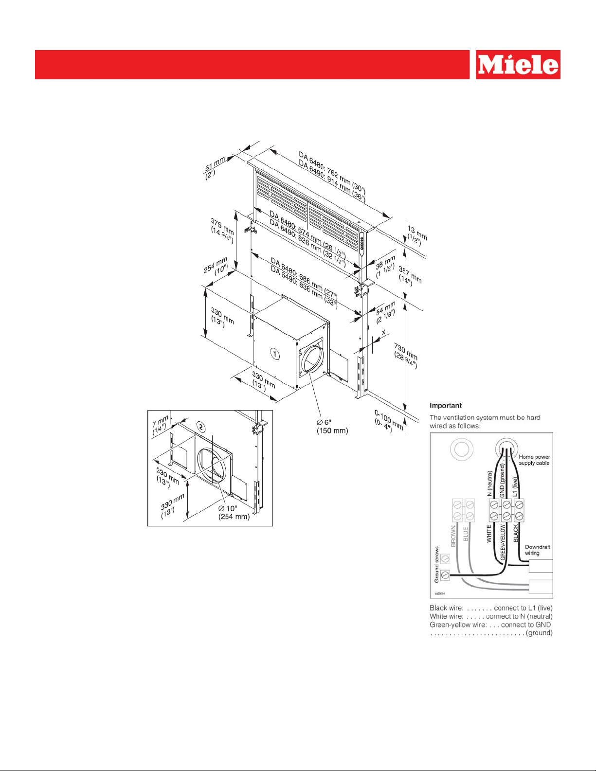
DA 6480 30 Downdraft Ventilation Hood
”
DA 6490 36” Downdraft Ventilation Hood
Location Codes
1 DAG 500 Internal blower – The blower box can be mounted in such a way that the
vent collar is aligned to the left, the right, downwards or towards the rear, as desired.
2 Connection plate when using the DAG 1000 external blower. The blower or the
connection plate can also be mounted in the same position on the rear of the
Appliance.
X = Distance to the rear of the cabinet or wall. Must be a minimum of ½” (13 mm).
Exhaust duct connection diameters
DA 6480, DA 6490 with internal blower DA 6480, DA 6490 with external blower
DAG 500 Internal Blower - 6” Ø (150 mm) DAG 1000 External Blower- 10” Ø (254 mm)
Item 28648050USA – DA 6480 Shipping weight 44 lbs (20 kg)
Shipping dimensions 31 5/16” (795 mm) L x 8 1/4” (210 mm) W x 33 1/16” (840 mm) H
Item 28649050USA – DA 6490 Shipping weight 50.7 lbs (23 kg)
Shipping dimensions 37“ (940 mm) L x 8 1/4” (210 mm) W x 33 1/16” (840 mm) H
The hood requires a 120 VAC, 60 Hz, 15 A hard wire connection to the terminal.
All electrical work should be performed by a qualified electrician.
All installations must be done in accordance with local codes.
Not intended for use with Miele CombiSets or KM2355 gas cooktop
Drawing is not to scale
Specification Sheets TRS 04302015
Page 2
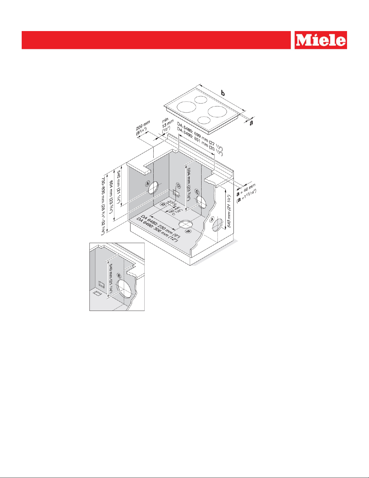
Cut-out Dimensions Page 2 o f 7
DA 6480 30 Downdraft Ventilation Hood
”
DA 6490 36” Downdraft Ventilation Hood
Location Codes
A – Cooktop Overhang
B – Cooktop Minimum Width
DA6480: 28” (711 mm)
DA6490: 34” (864 mm)
C – Vented rear
D – Feed the power cord and control cable when using an external blower downwards or to the rear.
Exhaust duct connection diameters
DA 6480, DA 6490 with internal blower DA 6480, DA 6490 with external blower
DAG 500 Internal Blower - 6” Ø (150 mm) DAG 1000 External Blower- 10” Ø (254 mm)
Notes:
Not to be used with Miele CombiSet units
The specified dimensions minimum cut-out dimensions must be observed.
IfIf anan ovenoven isis installedinstalled iinn ffrontront ofof thethe vventilationentilation systsystemem, ensensuurree tthathat allall installatioinstallationn dimensiodimensionnss andand guidelinguidelineess regardregardiinngg
ventilations systems.
Be aware of kitchen cabinets, back splashes and/or racks in the area of the ventilation system and the cooktop. Ensure
that the area where the vent rises is free of obstacles.
Make sure that any required minimum distance between the front edge of the countertop and the front edge of the
cooktop is maintained.
All installations must be done in accordance with local codes.
Not intended for use with Miele CombiSets or KM2355 gas cooktop
Drawing is not to scale Specification Sheets TRS 04302015
Page 3
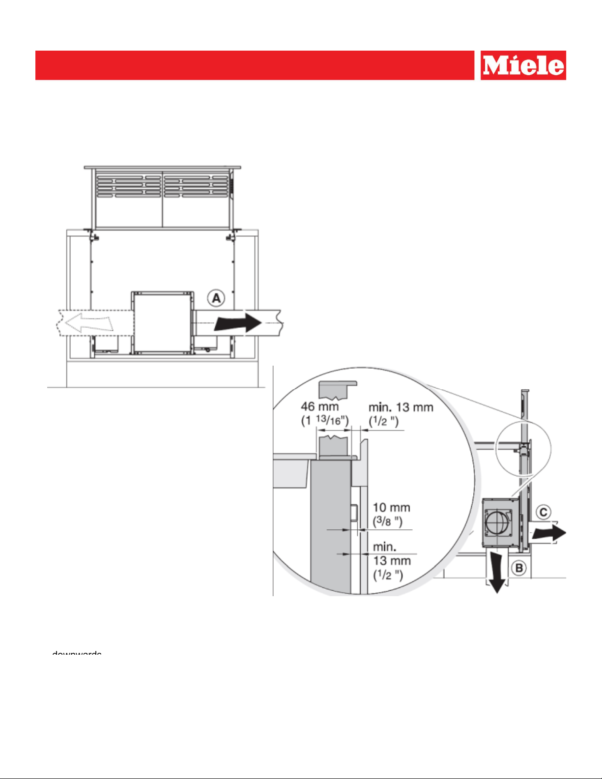
Product and Cut-out Dimensions Page 3 o f 7
DA 6480 30 Downdraft Ventilation Hood
B
downwards
”
DA 6490 36” Downdraft Ventilation Hood
Exhaust air ducting using the DAG 500 internal blower, installed on the front of the appliance [vent duct 6” ø (150 mm)]
A to the left or right
C to the rear
If the blower is being installed at the rear of the appliance, a cut-out must be made in the rear of the cabinet or wall
where it can be mounted and appropriate clearances must be maintained behind the cabinet.
All installations must be done in accordance with local codes
Not intended for use with Miele CombiSets or KM2355 gas cooktop
Drawing is not to scale
Specification Sheets TRS 04302015
Page 4

Product and Cut-out Dimensions Page 4 o f 7
DA 6480 30 Downdraft Ventilation Hood
”
DA 6490 36” Downdraft Ventilation Hood
DAG 500 Internal Blower
Shown with interior
mounted DAG 500
vent motor
DAG 500 mounted in front of the exhaust system. DAG 500 mounted behind the exhaust system.
DAG 500 Internal Blower exhaust diameter- 6” Ø (150 mm) Note that the blower must be accessible to install the
Maximum load with interior mounted
Maximum load with interior-mounted
DAG 500 vent motor…………………420 W
Item 28996319USA – DAG 500 Shipping weight 23 lbs (10.5 kg)
Shipping dimensions 24“ (610 mm) L x 18 5/16” (465 mm) W x 18 1/8” (460 mm) H
All installations must be done in accordance with local codes.
Not intended for use with Miele CombiSets or KM2355 gas cooktop
Drawing is not to scale
venting ductwork
Specification Sheets TRS 04302015
Page 5

Product and Cut-out Dimensions Page 5 o f 7
DA 6480 30 Downdraft Ventilation Hood
Exhaust air ducting to the front
Exhaust air ducting to the rear
”
DA 6490 36” Downdraft Ventilation Hood
DAG 1000 External Blower
Installation using the
DAG 1000 external blower
connection plate
.
Note that the back must be accessible for installation
of the venting ductwork
If using the external blower, install a connection cable between the ventilation system
and the external blower.
DAG 1000 External Blower exhaust diameter- 10” Ø (254 mm)
Maximum Load
with exterior-mounted
DAG 1000 vent motor……………….210 W
All installations must be done in accordance with local codes.
Not intended for use with Miele CombiSets or KM2355 gas cooktop
Drawing is not to scale
.
Specification Sheets TRS 04302015
Page 6

Product Dimensions Page 6 o f 7
DA 6480 30 Downdraft Ventilation Hood
¾
Conduit Size
”
DA 6490 36” Downdraft Ventilation Hood
DAG 1000 External Blower
DAG 1000 External Blower exhaust diameter- 10” Ø (254 mm)
Item 28996291USA – DAG 1000 Shipping weight 55 lbs (25 kg)
Shipping dimensions 36 1/4“ (920 mm) L x 13 1/4” (336 mm) W x 30” (762 mm) H
All installations must be done in accordance with local codes.
Not intended for use with Miele CombiSets or KM2355 gas cooktop
Drawing is not to scale
10” ø
Specification Sheets TRS 04302015
Page 7

Product and Cut-out Dimensions Page 7 o f 7
DA 6480 30 Downdraft Ventilation Hood
2
”
DA 6490 36” Downdraft Ventilation Hood
Downdraft Recirculation Kit DUU 2900
3
1
Details
Item 09162160
Cabinet cut-out 15 7/16” x 8 13/16” (392 mm x 224 mm)
To be vented out the sides or base of cabinet.
5 7/8” Vent port can be mounted in 3 positions
Discharge Grill exhaust is 180°
Two - Item number 09162160 - DKF 18-1 Charcoal filters included
All installations must be done in accordance with local codes.
Not intended for use with Miele CombiSets or KM2355 gas cooktop
Drawing is not to scale
Specification Sheets TRS 04302015
 Loading...