

Page 1

Operating and installation instructions
Ventilation System
DA 210-2
DA 220-2
To prevent accidents
and machine damage,
read these instructions
before
installation or use.
UV
M.-Nr.
05 814 420
Page 2
Table of Contents
IMPORTANT SAFETY INSTRUCTIONS
Guide to the appliance
DA 210-2 . . . . . . . . . . . . . . . . . . . . . . . . . . . . . . . . . . . . . . . . . . . . . . . . . . . . . . . . . 7
DA 220-2 . . . . . . . . . . . . . . . . . . . . . . . . . . . . . . . . . . . . . . . . . . . . . . . . . . . . . . . . . 8
Functional description
Operation
Main power switch . . . . . . . . . . . . . . . . . . . . . . . . . . . . . . . . . . . . . . . . . . . . . . . . . 11
Turning on the fan . . . . . . . . . . . . . . . . . . . . . . . . . . . . . . . . . . . . . . . . . . . . . . . . . 11
Selecting the power level. . . . . . . . . . . . . . . . . . . . . . . . . . . . . . . . . . . . . . . . . . . . 11
Delayed Shut Down . . . . . . . . . . . . . . . . . . . . . . . . . . . . . . . . . . . . . . . . . . . . . . . . 11
Turning off the fan . . . . . . . . . . . . . . . . . . . . . . . . . . . . . . . . . . . . . . . . . . . . . . . . . 12
Automatic Safety Shut Off. . . . . . . . . . . . . . . . . . . . . . . . . . . . . . . . . . . . . . . . . 12
Turning the lighting on/off . . . . . . . . . . . . . . . . . . . . . . . . . . . . . . . . . . . . . . . . . . . 12
Grease filter timer. . . . . . . . . . . . . . . . . . . . . . . . . . . . . . . . . . . . . . . . . . . . . . . . . . 13
Checking the grease filter timer . . . . . . . . . . . . . . . . . . . . . . . . . . . . . . . . . . . . 13
Reprogramming the grease filter timer . . . . . . . . . . . . . . . . . . . . . . . . . . . . . . 14
Cleaning and care
Cleaning the casing. . . . . . . . . . . . . . . . . . . . . . . . . . . . . . . . . . . . . . . . . . . . . . . . 15
Grease filters . . . . . . . . . . . . . . . . . . . . . . . . . . . . . . . . . . . . . . . . . . . . . . . . . . . . . 16
Changing the light bulb . . . . . . . . . . . . . . . . . . . . . . . . . . . . . . . . . . . . . . . . . . . . . 17
After Sales Service
Installation instructions
2
Page 3

IMPORTANT SAFETY INSTRUCTIONS
Read these Operating Instructions carefully before installing or
using the Ventilation System.
This appliance is designed to vent
This appliance is intended for resi
dential use only. Use the appliance
only for its intended purpose. The
manufacturer cannot be held re
sponsible for damages caused by
improper use of the hood.
This appliance complies with current
safety requirements. Improper use of
the appliance can lead to personal
injury and material damage.
Read all instructions before installing
or using for the first time.
Keep these operating instructions in
a safe place and pass them on to
any future user.
SAVE THESE INSTRUCTIONS
AND REVIEW THEM
PERIODICALLY
-
-
cooking smoke / odors only.
Be certain your appliance is prop
erly installed and grounded by a
qualified technician.
To guarantee the electrical safety of this
appliance, continuity must exist be
tween the appliance and an effective
grounding system. It is imperative that
this basic safety requirement be met. If
there is any doubt, have the electrical
system of the house checked by a
qualified electrician. The manufacturer
cannot be held responsible for damages caused by the lack, or inadequacy of, an effective grounding system.
Before connecting the appliance to
the power supply make sure that
the voltage and frequency listed on the
data plate correspond with the household electrical supply. This data must
correspond to prevent machine dam
age. Consult a qualified electrician if in
doubt.
-
-
-
CAUTION
For General Ventilating Use Only.
Do Not Use To Exhaust Hazardous
Or Explosive Materials And Vapors.
Installation work and repairs should
only be performed by a qualified
technician in accordance with all appli
cable codes and standards. Repairs
and other work by unqualified persons
could be dangerous and the manufac
turer will not be held responsible.
-
-
3
Page 4

IMPORTANT SAFETY INSTRUCTIONS
This equipment is not designed for
maritime use or for use in mobile
installations such as caravans or air
craft. However, under certain conditions
it may be possible for an installation in
these applications. Please contact the
nearest Miele dealer or the Miele Tech
nical Service Department with specific
requirements.
Before servicing, disconnect the
power supply by either removing
the fuse, unplugging the unit or manu
ally "tripping" the circuit breaker.
Before discarding an old appli
ance, unplug it from the power
supply and remove the power cord and
any doors to prevent hazards.
-
-
-
-
Use
Do not allow children to play with
or operate the appliance or its con
trols. Supervise its use by the elderly or
infirm.
Be careful when preparing a
flambé beneath the hood.
Flames may be drawn up into the hood
by the suction or grease filters may
catch fire.
Never operate gas burners without
pots.
Do not leave cooking surfaces un
attended while in use. Overheated
food, oil and grease can catch fire.
Do not use the hood without the
grease filters in place.
Clean the grease filters regularly.
Dirty filters are a fire hazard.
Do not use a steam cleaner to
clean the hood. Steam could penetrate electrical components and cause
a short circuit.
-
-
In areas subject to infestation by
cockroaches or other pest, keep
the appliance and its surroundings
clean at all times. Any damage caused
by cockroaches or other pest will not
be covered under warranty.
4
Page 5

IMPORTANT SAFETY INSTRUCTIONS
Installation
When installing the hood, make
sure that the following minimum
safety distances between Miele
cooktops and the hood are maintained.
22" (55 cm) above electric cooktops
–
26" (65 cm) above gas cooktops
–
26" (65 cm) above an open grill
–
For non-Miele cooking appliances
maintain the safety distances recom
mended by the cooktop manufacturer
in their installation and operating in
structions.
If there is more than one appliance beneath the hood and they have different
minimum safety distances always select the greater distance.
Do not use an extension cord to
connect the appliance to electricity.
Extension cords do not guarantee the
required safety of the appliance, (e.g.
danger of overheating).
-
-
Never connect an exhaust hood to
an active chimney, dryer vent, vent
flue, or room ventilating ductwork. Seek
professional advice before connecting
an exhaust hood vent to an existing, in
active chimney or vent flue.
Make sure that the airflow in the
room is sufficient for combustion
and exhausting of all non-electric heat
ing appliances (water heaters, gas
cooktops, gas ovens, etc.), otherwise
backdrafts may occur. Follow the heat
ing manufacturer’s guidelines and
safety standards or those published by
the National Fire Protection Association
(NFPA), or the American Society for
Heating, Refrigeration and Air Conditioning Engineers (ASHRAE). If in
doubt, consult an experienced professional.
-
-
-
Do not install this hood over
cooktops burning solid fuel.
Any fittings, sealant, or materials
used to install the ductwork must
be made of approved non-flammable
materials.
5
Page 6

IMPORTANT SAFETY INSTRUCTIONS
WARNING
TO REDUCE THE RISK OF INJURY
TO PERSONS IN THE EVENT OF A
RANGE TOP GREASE FIRE,
OBSERVE THE FOLLOWING:
Smother flames with a close fitting
lid, cookie sheet, or metal tray, then
turn off the burner.
Be careful to prevent burns.
If the flames do not go out immediately,
evacuate and call the fire depart
ment.
Never pick up a flaming pan -
You may be burned.
Do not use water, including wet
dishcloths or towels - a violent
steam explosion will result.
Use an extinguisher
only if:
– You know you have a Class ABC ex-
tinguisher, and you already know
how to operate it.
-
–
The fire is small and contained in the
area where it started.
–
The fire department is being called.
–
You can fight the fire with your back
to an exit.
The manufacturer cannot be held lia
ble for damage caused by non-com
pliance with these Warning and
Safety instructions.
6
-
-
Page 7
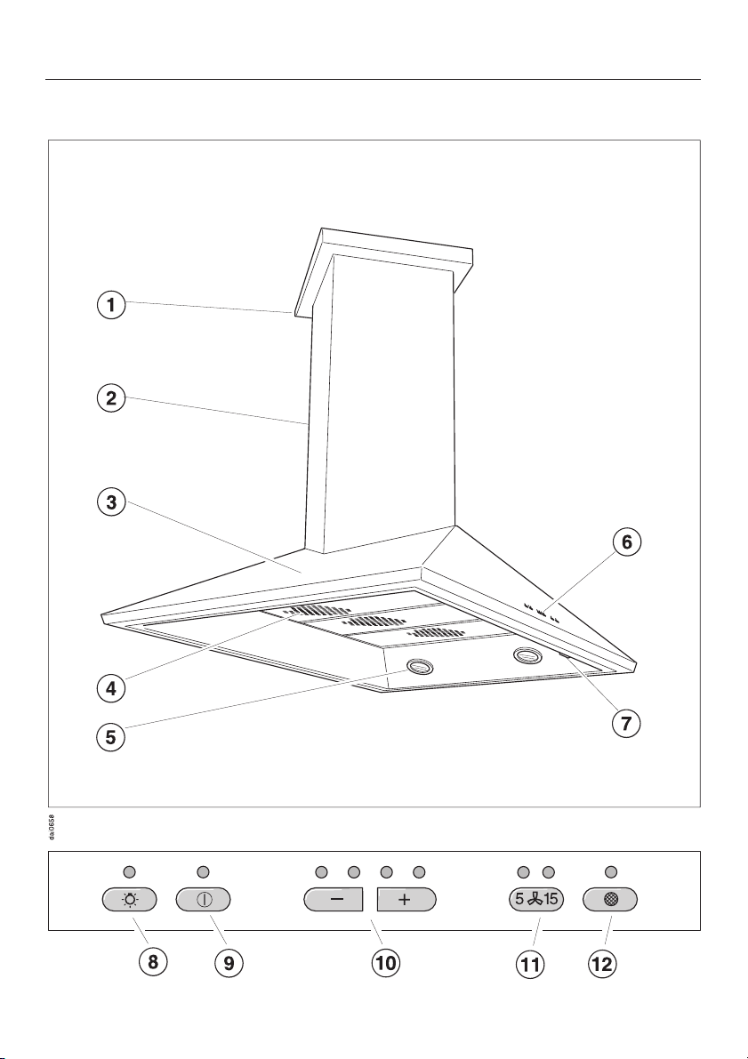
DA 210-2
Guide to the appliance
7
Page 8
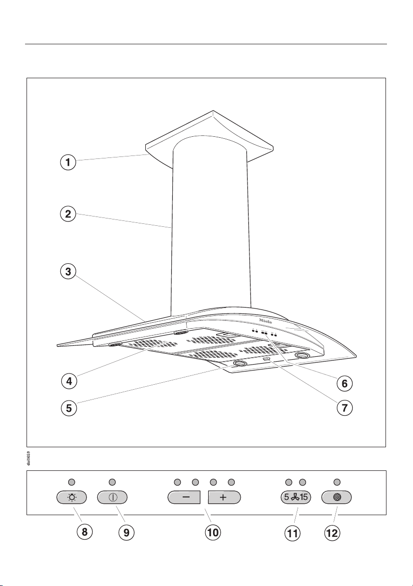
Guide to the appliance
DA 220-2
8
Page 9

Guide to the appliance
a Cover plate
b Chimney
c Canopy
d Grease filters
e Overhead lighting
f Control panel
g Main power switch
h Light button
i On/Off button
j Fan power level buttons
Four fan speed selection.
k Delayed Shut Down
This button activates the Delayed Shut
Down feature. The fan can be set to
turn off automatically after either 5 or 15
minutes.
l Grease filter button
The indicator above to the grease filter
button lights when the grease filters
need to be cleaned.
This button is also used:
– to reset the grease filter timer after
cleaning the grease filters (see
"Cleaning and Care").
–
to show how long the grease filter
has been in use (see "Operation /
Grease filter timer").
–
to change the number of hours
counted by the grease filter timer
(see "Operation / Reprogramming the
grease filter timer").
9
Page 10

Functional description
The ventilation hood works by air ex
traction. The air is drawn in and
cleaned by the grease filters and di
rected outside.
The hood comes equipped with a
non-return flap. This flap automatically
closes when the hood is turned off so
that no exchange of outside air and
room air can occur. When the hood is
turned on, the air pressure of the ex
haust fan automatically opens the flap
blowing the inside air and cooking
odors outside.
-
-
-
10
Page 11
Operation
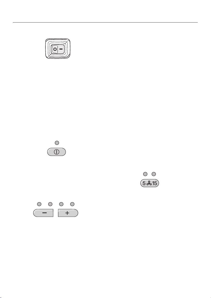
Main power switch
Press the main power switch to "I". The
fan and the lighting can now be oper
ated.
If the appliance is not going to be used
for a long period of time (e.g. while va
cationing) turn the appliance off by
pressing the main power switch to "0".
The next time it is turned on, the hood
will operate at the level previously used.
-
-
Turning on the fan
^ Press the On/Off button.
The fan runs at power level "2".
The On/Off indicator lights.
Intensive setting
Level "4" (yellow indicator) should be
used for a short period when frying or
cooking food with a strong aroma.
Fan performance
The maximum air flow capacity is
625 cfm. Factors such as narrow duct
diameter and bends will affect this
value.
Level 1 operates at 40% capacity
Level 2 operates at 60% capacity
Level 3 operates at 80% capacity
Level 4 operates at 100% capacity
Delayed Shut Down
If odors or smoke remain in the kitchen
after cooking has been completed, the
Delayed Shut Down feature can be selected to allow the hood to continue
running for either 5 or 15 minutes.
Selecting the power level
^
Use the _ buttons to select the
desired power level.
& =increases the fan speed
$ =decreases the fan speed
Level "1" to "3" (green indicators) are
usually sufficient for normal cooking.
^
Press the Delayed Shut Down button
while the fan is still running.
Press once = 5 minute delay
(left indicator lights)
Press twice = 15 minute delay
(right indicator lights)
To cancel the Delayed Shut Down fea
ture press the button again.
-
11
Page 12

Operation
Turning off the fan
Press the On/Off button to turn the
^
fan off.
The indicator goes out.
Automatic Safety Shut Off
The fan will turn off automatically
10 hours after the last button was acti
vated. The lighting however will remain
on.
^ Press the On/Off button to turn the
fan back on again.
Turning the lighting on/off
The overhead lighting can be turned on
and off independently of the fan.
Press the light button to turn on the
^
lighting.
The light button indicator illuminates.
Press the light button again to turn off
^
the lighting.
12
Page 13
Operation
Grease filter timer
A timer monitors the hours of fan opera
tion. The indicator for the grease filter
will light after 30 hours of operation. The
grease filters must then be cleaned.
After the grease filters have been
cleaned and put in place, the grease fil
ter timer must be reset.
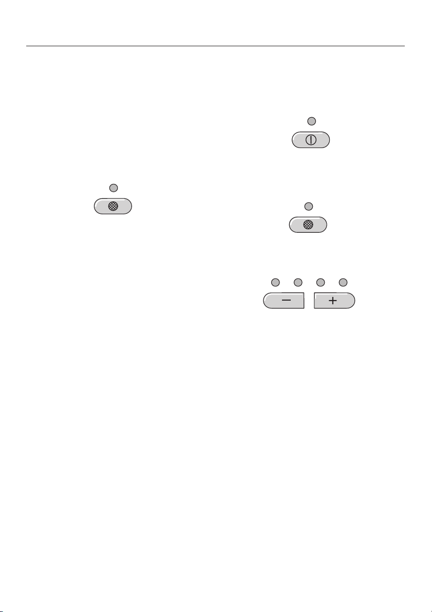
To do this, press the grease filter but
^
ton for about 3 seconds.
The indicator will go out.
Checking the grease filter timer
To check the percentage of time al
ready used:
Press the On/Off button to turn the
^
fan on.
^ Press the grease filter button.
The number of flashing _ indicators
show the percentage of programmed
hours that have been used.
-
1 indicator = less than 25 %
2 indicators = less than 50 %
3 indicators = less than 75 %
4 indicators = less than 100 %
This information will remain stored in
memory in the event of a power failure.
13
Page 14
Operation
Reprogramming the grease filter
timer
The grease filter timer is preset to 30
hours. This time can be lengthened or
shortened to 20, 30, 40 or 50 hours.
A time of 20 hours should be pro
–
grammed in kitchens with frequent
pan or deep frying.
A time of 20 hours should also be
–
programmed if the kitchen is only
used occasionally. Otherwise grease
which has accumulated over a long
period of time will harden on the fil
ters making cleaning more difficult.
-
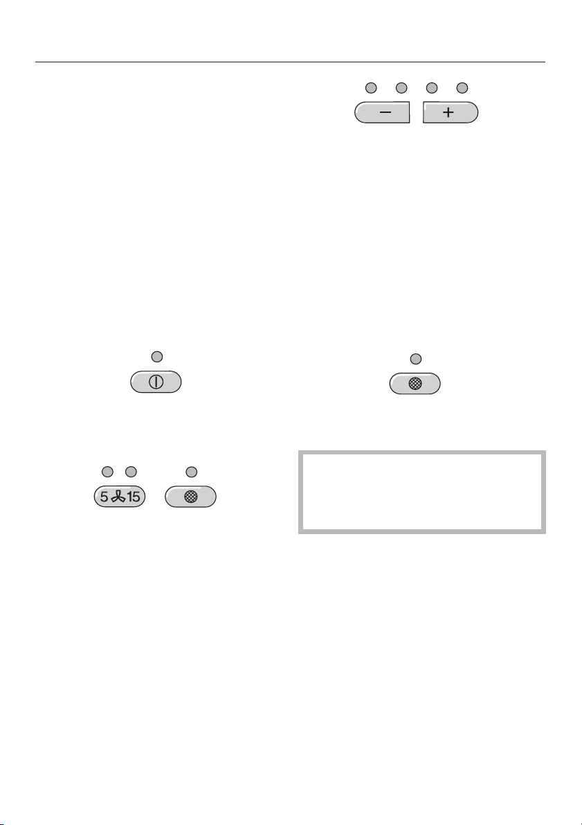
The indicator for the grease filter and
one of the _ indicators will flash.
The lit _ indicator shows the pro
grammed time:
1st indicator from the left = 20 hours
2nd indicator from the left = 30 hours
3rd indicator from the left = 40 hours
4th indicator from the left = 50 hours.
Use the $ or & button to select the
^
desired time.
-
^ Press the On/Off button to turn off the
fan.
^
Press the Delayed Shut Down and
grease filter buttons at the same time.
14
^ Store the selection by pressing the
grease filter button.
If the procedure is not stored within
4 minutes of programming, the hood
will automatically default to the "old"
data.
Page 15
Cleaning and care
Before cleaning or servicing the
hood, disconnect it from the power
supply by either removing the fuse,
unplugging it from the outlet or man
ually "tripping" the circuit breaker.
Cleaning the casing
Never use abrasive cleaners,
,
scouring pads, steel wool or caustic
(oven) cleaners on the hood. They
will
damage the surface.
All external surfaces and controls can
^
be cleaned with warm water and liquid dish soap applied with a soft
sponge.
^ Wipe dry using a soft cloth.
Do not use too much water when
cleaning the controls. Water could
penetrate into the electronics and
cause damage.
Stainless steel
Stainless steel surfaces can be cleaned
using a non-abrasive stainless steel
-
cleaner.
To help prevent resoiling, a conditioner
for stainless steel can also be used.
Apply sparingly with even pressure.
Stainless steel colored controls
These controls may become discol
ored or damaged if not cleaned reg
ularly.
Do not use a stainless steel cleaner
on these controls.
-
-
^
Glass surfaces can be cleaned using
glass cleaner.
Avoid:
–
cleaning agents containing soda, ac
ids or chlorides,
–
abrasive cleaning agents e.g. pow
der or cream cleansers,
–
abrasive sponges, e.g. pot scourers
or sponges which have been previ
ously used with abrasive cleaning
agents.
These will damage the surface.
-
-
-
15
Page 16
Cleaning and care
Grease filters
The reusable metal grease filters re
move solid particles from the vented
kitchen air (grease, dust, etc).
The grease filters should be cleaned
every 3-4 weeks or whenever the
grease filter timer indicator lights.
A dirty filter is a fire hazard.
Clean the filters
^
-
- by hand: use a scrub brush in
warm water with a mild detergent.
- in a dishwasher: place the filters in
the lower basket, making sure that
the spray arm is not blocked.
Depending on the detergent, clean
ing the grease filters in a dishwasher
may cause permanent discoloration
of the filter surface. Performance of
the filter will not be affected by this
discoloration.
^ After cleaning, the filters can be
placed on a towel to air dry.
^ While the filters are removed, clean
any dirt or grease from the filter casing to prevent the risk of fire.
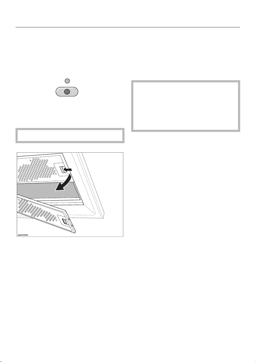
When putting the grease filters back
make sure that the locking clips are visible facing down towards the cooking
surface.
-
^
To remove the grease filters press the
locking clips in towards the middle of
the filter. Holding carefully, lower and
remove the filter.
16
If the filters are incorrectly installed, insert a small screwdriver into the slit
along its edge to disengage it from the
casing.
^
After returning the grease filters,
press the grease filter button for
3 seconds to reset the timer. The indi
cator light will go out.
^
If the grease filters are cleaned be
fore the timer has reached its maxi
mum, the grease filter button should
be pressed for 6 seconds to reset the
counter to zero.
-
-
-
Page 17
Cleaning and care
Changing the light bulb
Before changing the light bulbs, dis
connect the hood from the power
supply by either removing the fuse,
unplugging it, or manually "tripping"
the circuit breaker.
When in use halogen bulbs become
extremely hot, and they can burn
your hands. Do not attempt to
change the bulbs until they have
had sufficient time to cool down.
Do not touch the bulb surface. Fingerprints or body oils deposited on
the bulb will decrease the life of the
bulb. Please follow the bulb manufacturer’s instructions.
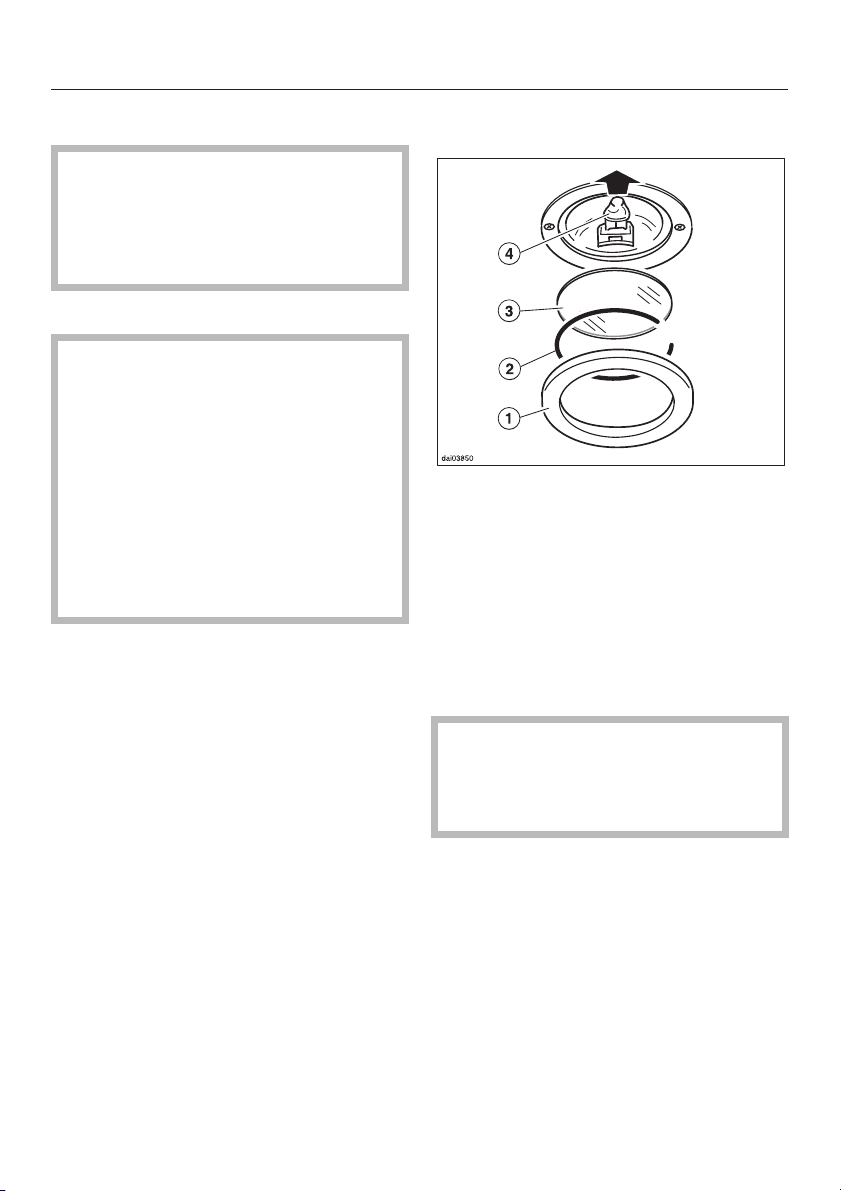
To change a bulb:
-
^ Remove the outer ring, a.
^ Support the glass, c, while detach-
ing the circlip, b. Be careful not to let
the glass fall out.
^ Pull the old bulb, d, out of its socket
and replace it with a new one.
^ Reinstall the glass, circlip and outer
ring.
Never use the lights without the
glass, c, installed. The glass is spe
cially made to filter harmful light
rays.
-
17
Page 18

After Sales Service
In the event of a fault which you cannot
correct yourself please contact:
Your Miele Dealer
–
or
The Miele Technical Service
–
Department
USA 1-800-999-1360
CDN 1-800-565-6435
When contacting the Technical Service
Department, please quote the model
and serial number of your appliance.
These are shown on the data plate
which is visible when the grease filter is
removed.
18
Page 19
Installation instructions
Page 20

Table of Contents
Caring for the environment
Structural support
Electrical data
Appliance dimensions
DA 210-2 . . . . . . . . . . . . . . . . . . . . . . . . . . . . . . . . . . . . . . . . . . . . . . . . . . . . . . . . 24
DA 220-2 . . . . . . . . . . . . . . . . . . . . . . . . . . . . . . . . . . . . . . . . . . . . . . . . . . . . . . . . 25
Installation
Air extraction
20
Page 21

Caring for the environment
Disposal of packing material
The cardboard box and packing materi
als protect the appliance during ship
ping. They have been designed to be
biodegradable and recyclable. Please
recycle.
Ensure that any plastic wrappings,
bags etc. are disposed of safely and
kept out of the reach of children. Dan
ger of suffocation!
-
-
Disposal of an old appliance
Old appliances may contain materials
that can be recycled. Please contact
your local recycling authority about the
possibility of recycling these materials.
Before discarding an old appliance,
unplug it from the outlet and cut off
its power cord and remove any
doors to prevent hazards.
21
Page 22
Structural support
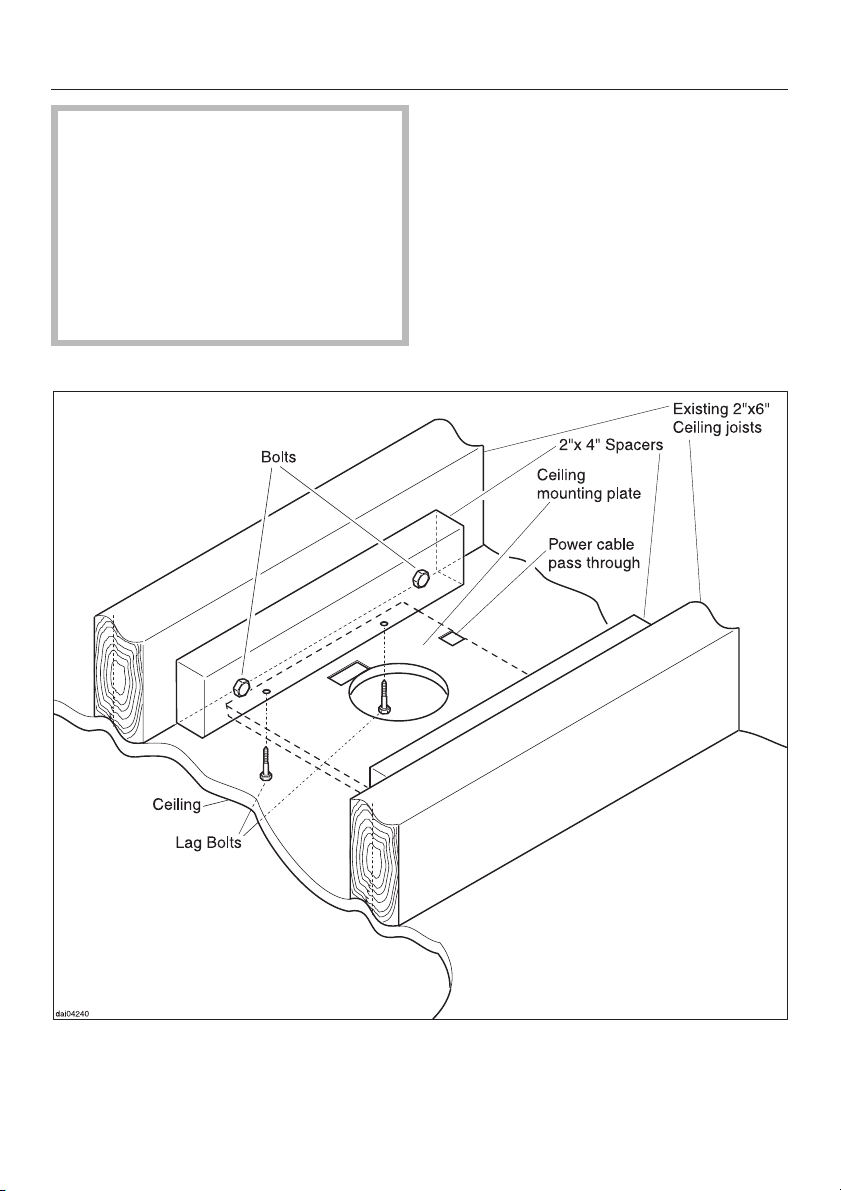
The ceiling mounting plate will sup
port the weight of the hood. This
ceiling plate must be attached to
rigid structural framing that is sup
ported in its entirety by the ceiling
joists, or to the ceiling joists directly.
Do not attach the plate directly to the
ceiling by using anchors, mollies or
toggle bolts.
-
-
22
Page 23

Electrical data
All electrical work should be per
formed by a qualified electrician in
strict accordance with national and
local safety regulations.
Installation, repairs and other work
by unqualified persons could be
dangerous. The manufacturer can
not be held responsible for unautho
rized work.
Ensure that power to the appliance
is OFF while installation or repair
work is performed.
Verify that the voltage, load and circuit
rating information found on the data
plate (located behind the grease filters), match the household electrical
supply before installing the hood.
If there is any question concerning the
electrical connection of this appliance
to your power supply, please consult a
licensed electrician or call Miele’s Technical Service Department.
USA 1-800-999-1360
CDN 1-800-565-6435
-
-
Important
The hood must be hard wired accord
ingly:
Black/Red wire:. . . . connect to L1 (live)
White wire: . . . . . connect to N (neutral)
Green wire: . . connect to GND (ground)
Maximum load
DA 210-2, 220-2 . . . . . . . . . . . . . 430 W
Lighting . . . . . . . . . . . . . . . . . . 4 x 20 W
Voltage . . . . . . . . . . . . . . . . . . . . . 120 V
Frequency . . . . . . . . . . . . . . . . . . 60 Hz
Circuit rating. . . . . . . . . . . . . . . . . . 15 A
-
WARNING:
THIS APPLIANCE MUST BE
GROUNDED
23
Page 24
Appliance dimensions
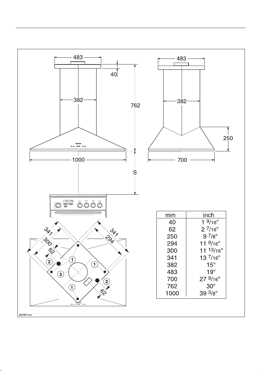
DA 210-2
a Mounting bolt holes
b Alternative positions for feeding through the power cord
c Exhaust connection 6" (150 mm) diameter
24
Page 25
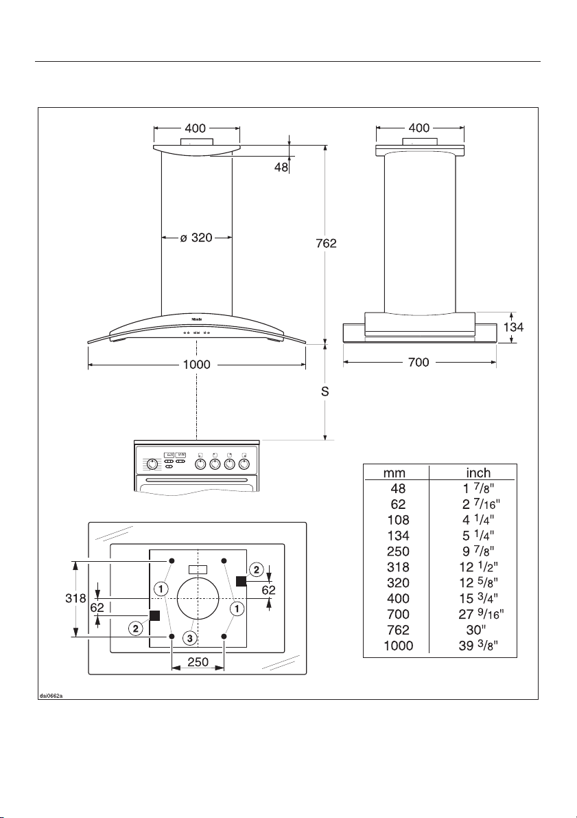
DA 220-2
Appliance dimensions
a Mounting bolt holes
b Alternative positions for feeding through the power cord
c Exhaust connection 6" (150 mm) diameter
25
Page 26
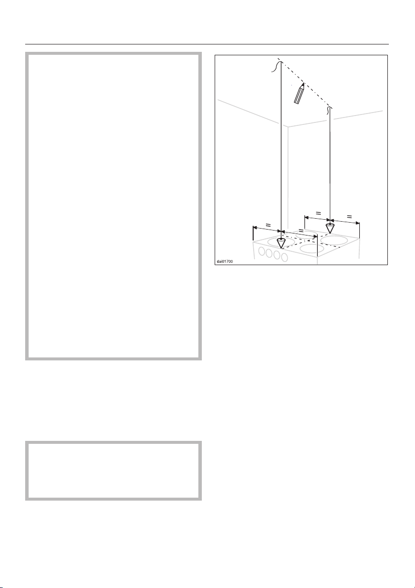
Installation
Do not install this exhaust hood over
cooktops burning solid fuel.
When installing the hood, make sure
that the following minimum dis
tance (S) between the top of a Miele
cooking surface and the bottom of
the hood is:
- 22" (55 cm) above electric cooktops
- 26" (65 cm) above gas cooktops
- 26" (65 cm) above an open grill
For non-Miele cooking appliances
maintain the safety distances recom
mended by the cooktop manufacturer in their installation and operating instructions.
-
-
If there is more than one appliance
beneath the hood and they have different minimum safety distances always select the greater distance.
See "Warning and Safety instructions" for further information.
26" (65 cm) is recommended for all in
stallations to allow for optimum work
space under the hood.
CAUTION:
During the installation process,
please be careful of sharp edges
that can cause harm.
^ Make a line on the ceiling going from
the rear of the cooktop towards the
front and centered over the cooktop.
^ Cut a 7
1
/2" (190 mm) hole in the ceiling for the exhaust duct to pass
through. The exhaust connection has
a 6" (150 mm) diameter.
-
26
Page 27
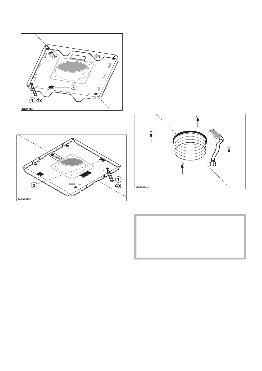
Mounting plate: DA 210-2
Installation
Feed the ductwork and power cable
^
through their respective holes in the
ceiling.
If 6" (150 mm) ductwork is not possible
then 5" (125 mm) ductwork can be
used in conjunction with a reducing
collar available from the Miele Technical
Service Department (see "Installation /
Air extraction" for further details).
Mounting plate: DA 220-2
^
Hold the mounting plate up to the
ceiling so that the orange arrow faces
the front of the hood and aligns with
the line drawn on the ceilling.
Mark the position of the four mount
ing bolts a for securing the mounting
plate and determining the position of
the hole the power cord b will pass
through.
Select the hole providing the shortest
route for the power cable b to reach
the power terminal located at the top
of the hood’s chimney.
-
^ Drill four
3
/16" (5 mm) holes in the ceil-
ing.
The S10 wall anchors included in the
packaging are not for use in
USA/CDN. Be certain that the ceiling
is stable enough to support the
hood.
27
Page 28
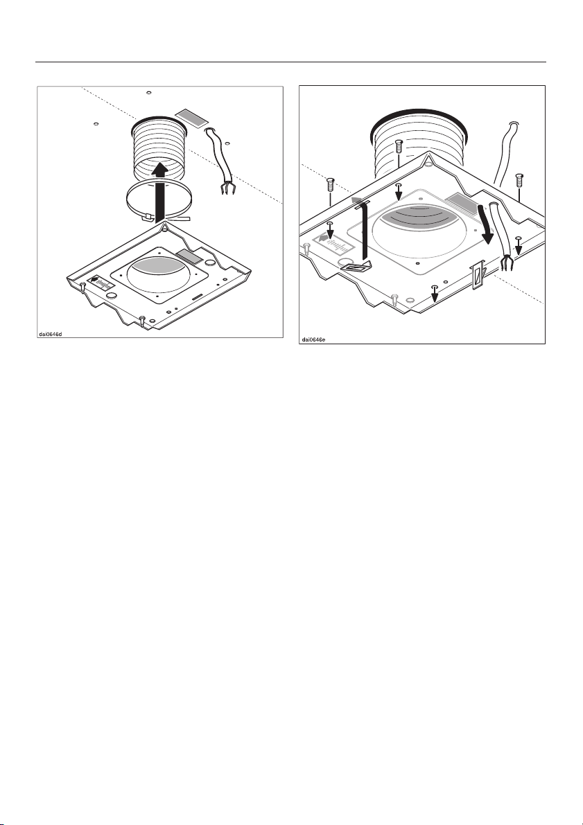
Installation
^ Secure the ducting to the mounting
plate using a hose clip.
^ Insert the short edge of the two
spring clips into their slots from below and pivot them 90° so that the
tab faces the center of the mounting
brake.
^ Pull the power cord through the
mounting plate.
^
Insert the four countersunk screws
M 6 x 20 into the recessed holes from
above.
^
Tape the screws from above to pre
vent them from being pushed up
wards when the nuts are tightened.
-
-
28
Page 29
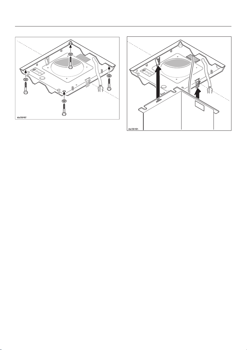
Screw the mounting plate through the
^
ceiling and into the structural framing
using 8 x 60 lag bolts and washers.
Once tight, make sure that the
mounting plate can safely support
the weight of the hood.
Installation
^ Using at least two people, lift the
hood and guide the spring clips
through their respective slots in the
flange at the top of the chimney.
Make sure they click into place and that
the hood is hanging securely from the
spring clips before allowing them to
carry the weight.
29
Page 30
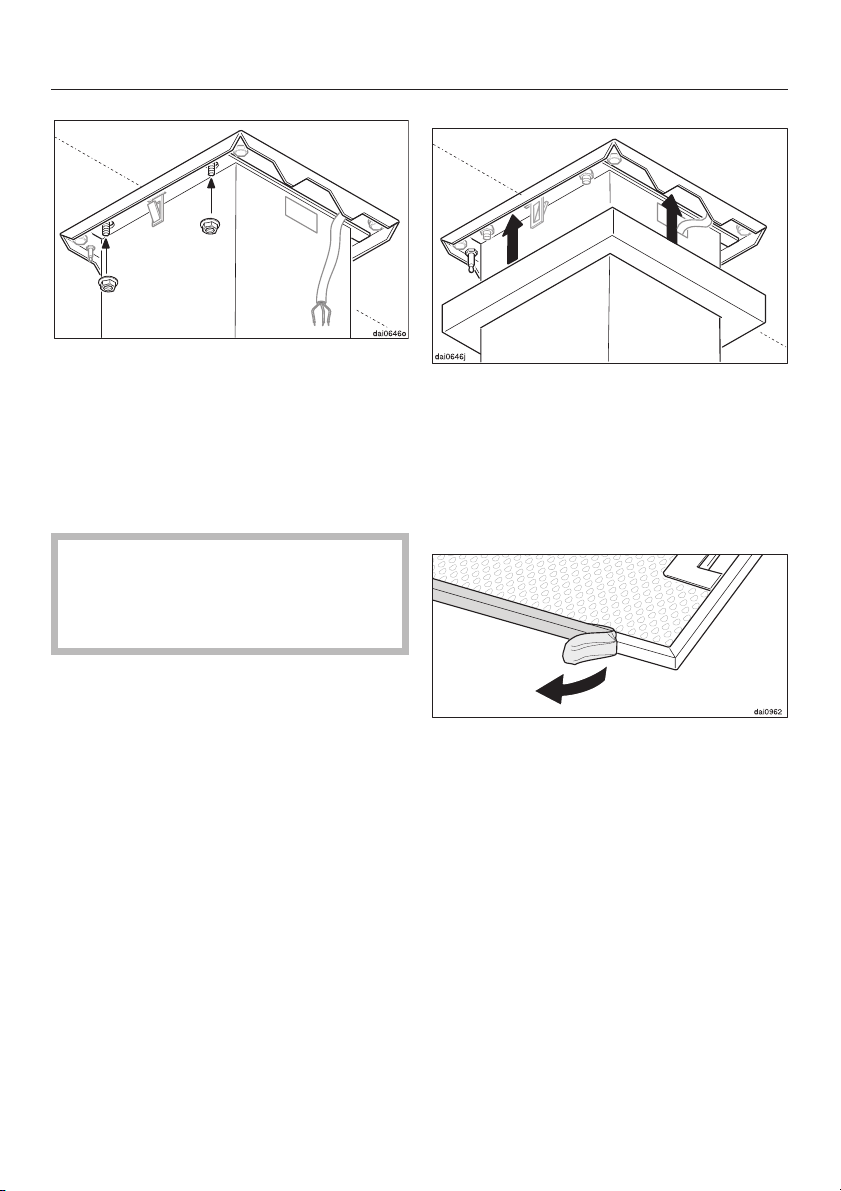
Installation
Bolt the flange firmly to the ceiling us
^
ing the four M6 nuts.
Shorten the power cable as much as
^
possible and attach it to the terminal
block inside the chimney. See "Electrical data".
Before connecting the appliance
read the "Warning and Safety Instructions" and "Electrical data" sections.
Finally, being careful not to scratch
^
the chimney, push the cover plate up
wards until the spring fixing clips
click into place. If installed correctly,
the cover should be secure and flush
against the ceiling.
-
30
^
Before using the appliance remove
the grease filter and remove the pro
tective foil from the filter frame. Re
turn filter.
-
-
Page 31
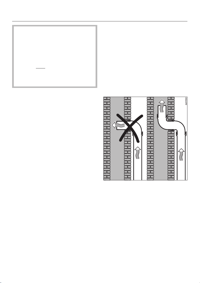
Danger of toxic fumes.
Gas cooking appliances release
carbon monoxide that can be harm
-
ful or fatal if inhaled. The exhaust
gases extracted by the hood
should be vented outside of the
building only
.
Do not terminate the exhaust
ducts in attics, garages,
crawlspaces, etc.
Please read and follow the "Warning
and Safety Instructions" to reduce the
risk of personal injury. Follow all local
building codes when installing the
hood.
Exhaust ducting and connections
– The ducting should be as short and
straight as possible, and the number
of sharp bends should be minimized.
Air extraction
Use smooth or flexible pipes made
–
from approved non-flammable mate
rials for exhaust ducting.
Where the ductwork is horizontal, it
–
must slope away from the hood at
1
/8" per foot (1cm per meter) to
least
prevent condensation dripping into
the appliance.
If the exhaust is ducted through an
–
outside wall, a Miele Telescopic Wall
Vent can be used.
-
– For most efficient air extraction, the
diameter of the ductwork should not
be less than 6" (150 mm). Use of flat
ducts also reduces the air extraction
efficiency.
–
Noise levels of the hood will increase
if flat ducts or round ducts of less
than 6" (150 mm) in diameter are
used.
WARNING
To reduce the risk of fire, only use
metal ductwork.
CAUTION
To reduce risk of fire and to properly
exhaust air, be sure to duct air out
side. Do not vent exhaust air into
spaces within walls or ceilings or
into attics, crawl spaces, or garages.
–
If the exhaust is ducted into an inac
tive flue, the air must be expelled
parallel to the flow direction of the
flue.
-
31
Page 32
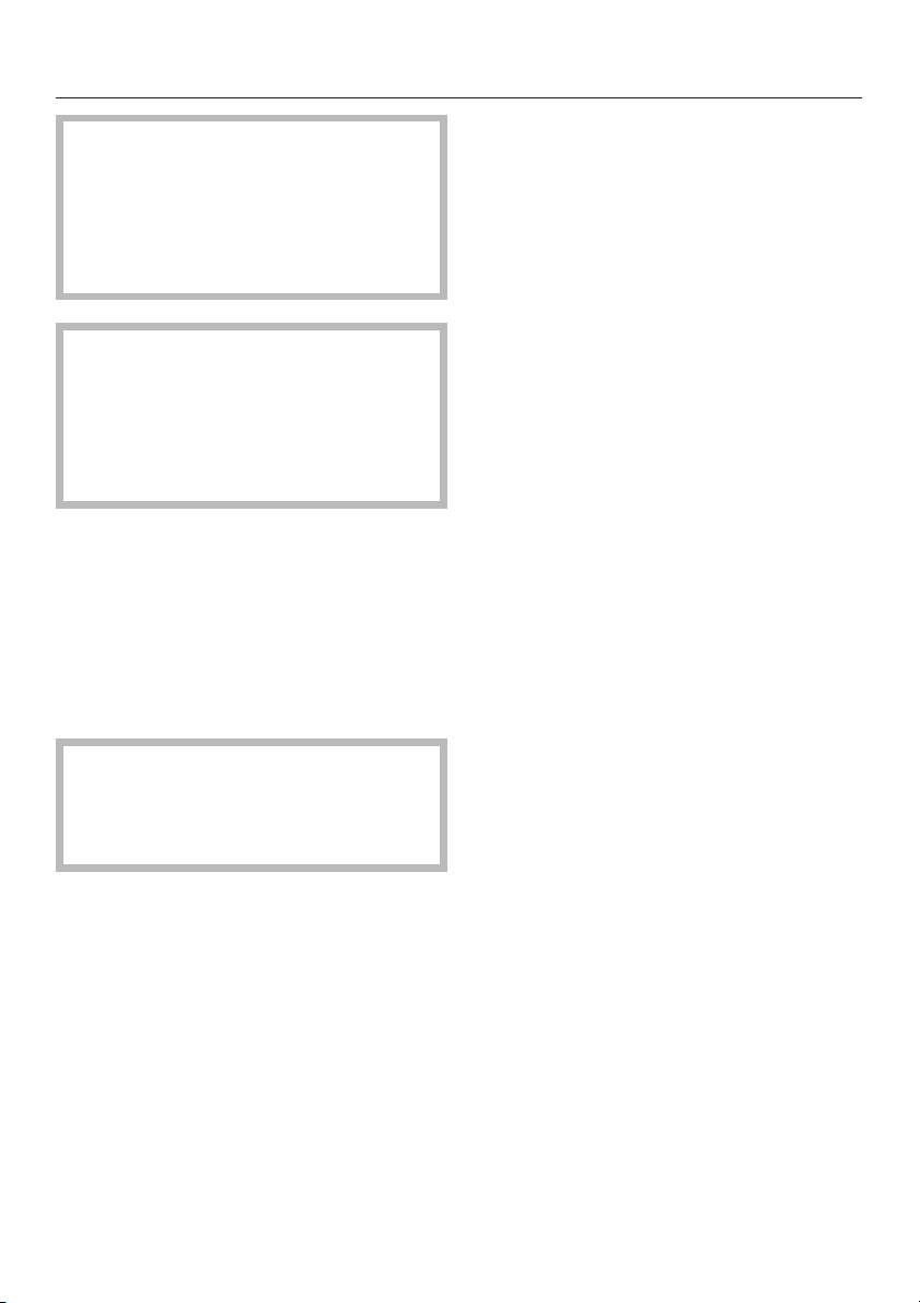
Air extraction
Never connect an exhaust hood to
an active chimney, dryer vent, vent
flue, or room venting ductwork. Seek
professional advice before connect
ing an exhaust hood vent to an exist
ing, inactive chimney or vent flue.
Ductwork with a diameter of less
than 6" (150 mm) should only be
used when absolutely necessary. As
duct diameter decreases, the hood’s
performance and sound levels will
be affected.
Important:
If the ductwork runs through rooms,
ceilings, garages, etc. where temperature variations exist, it may need to be
insulated to reduce condensation. In
some cases, a condensate trap may
also be required to collect and evaporate any condensate which may occur.
-
-
When installing a condensate trap,
ensure that it is positioned vertically
and if possible directly above the ex
haust outlet.
323334
-
Page 33

Page 34

Page 35

35
Page 36
Alteration rights reserved / 3402
This paper is made from cellulose bleached without the use of chlorine.
M.-Nr. 05 814 420 / V
00
 Loading...