

Page 1

Operating and Installation Instructions
Ventilation System
To prevent accidents and machine damage, read these instructions
before installation or use.
M.-Nr. 10 296 060en-US
Page 2

Contents
IMPORTANT SAFETY INSTRUCTIONS. . . . . . . . . . . . . . . . . . . . . . . . . . . . . . . . . 3
Description of functions . . . . . . . . . . . . . . . . . . . . . . . . . . . . . . . . . . . . . . . . . . . . 7
Guide to the ventilation system . . . . . . . . . . . . . . . . . . . . . . . . . . . . . . . . . . . . . . 8
Turning the light on/off ...............................................9
Fan control ........................................................9
Cleaning and care . . . . . . . . . . . . . . . . . . . . . . . . . . . . . . . . . . . . . . . . . . . . . . . . 10
Grease filters .....................................................11
Odor-free filter (active charcoal filter) ..................................13
Changing the light bulbs ............................................14
After Sales Service . . . . . . . . . . . . . . . . . . . . . . . . . . . . . . . . . . . . . . . . . . . . . . . 15
Installation instructions . . . . . . . . . . . . . . . . . . . . . . . . . . . . . . . . . . . . . . . . . . . 17
Caring for the environment. . . . . . . . . . . . . . . . . . . . . . . . . . . . . . . . . . . . . . . . . 18
Appliance dimensions. . . . . . . . . . . . . . . . . . . . . . . . . . . . . . . . . . . . . . . . . . . . . 19
Installation . . . . . . . . . . . . . . . . . . . . . . . . . . . . . . . . . . . . . . . . . . . . . . . . . . . . . . 21
Diverter .........................................................21
Under-cabinet installation ...........................................22
Wall mounting ....................................................23
Electrical connection. . . . . . . . . . . . . . . . . . . . . . . . . . . . . . . . . . . . . . . . . . . . . . 27
Exhaust ducting . . . . . . . . . . . . . . . . . . . . . . . . . . . . . . . . . . . . . . . . . . . . . . . . . . 28
Condensate trap ..................................................30
Technical data . . . . . . . . . . . . . . . . . . . . . . . . . . . . . . . . . . . . . . . . . . . . . . . . . . . 31
2
Page 3

IMPORTANT SAFETY INSTRUCTIONS
READ AND SAVE THESE
INSTRUCTIONS
Keep these instructions in a safe
place and pass them on to any future
user.
Read these instructions carefully
before installing or using the
Ventilation System.
This appliance is intended for
~
residential use only. Use the appliance
only for its intended purpose.
This appliance complies with current
~
safety requirements. Improper use of
the appliance can lead to personal
injury and material damage.
,CAUTION
For General Ventilating Use
Only. Do Not Use To Exhaust
Hazardous Or Explosive
Materials And Vapors.
This appliance is designed to vent
~
cooking smoke and odors only.
This appliance is suitable for
~
installation above gas or electric
cooking surfaces.
,WARNING
TO REDUCE THE RISK OF
FIRE, ELECTRIC SHOCK, OR
INJURY TO PERSONS,
OBSERVE THE FOLLOWING:
a) Use this appliance only in the
~
manner intended by the manufacturer.
If you have questions, contact Miele.
b) Before servicing or cleaning the
~
appliance, switch power off at the ser
vice panel and lock the service
disconnecting means to prevent power
from being switched on accidentally. If
the service disconnecting means
cannot be locked, securely fasten a
prominent warning device, such as a
tag, to the service panel.
c) Be certain your appliance is
~
properly installed and grounded by a
qualified technician.
To guarantee the electrical safety of this
appliance, continuity must exist
between the appliance and an effective
grounding system. It is imperative that
this basic safety requirement be met. If
there is any doubt, have the electrical
system of the house checked by a
qualified electrician.
-
This appliance is not intended for
~
outdoor use.
This appliance must not be used in
~
a non-stationary location (e.g. on a
ship).
3
Page 4

IMPORTANT SAFETY INSTRUCTIONS
d) Before connecting the appliance
~
to the power supply make sure that the
voltage and frequency listed on the
data plate correspond with the
household electrical supply.
This data must correspond to prevent
appliance damage. If in doubt consult a
qualified electrician.
e) Installation work and repairs
~
should only be performed by a qualified
technician in accordance with all
applicable codes and standards.
Repairs and other work by unqualified
persons could be dangerous.
f) Only open the casing as
~
described in the enclosed "Installation
diagram" and in the "Cleaning and care"
section of this manual. Under no
circumstances should any other parts
of the casing be opened. Tampering
with electrical connections or
components and mechanical parts is
highly dangerous to the user and can
cause operation faults.
g) Before discarding an old
~
appliance, disconnect it from the power
supply and remove the power cord to
prevent hazards.
Use
,WARNING
TO REDUCE THE RISK OF A
COOKTOP GREASE FIRE:
a) Never leave surface units
~
unattended at high settings. Boilovers
cause smoking and greasy spillovers
may ignite. Heat oils slowly on low or
medium settings.
b) Always turn the hood on when
~
cooking at a high heat.
c) Clean the ventilation hood
~
frequently. Grease should not be
allowed to accumulate on the fan or
filter.
d) Use the proper pan size. Always
~
use cookware appropriate for the size
of the cooking area.
e) Do not flambé or grill with an
~
open flame beneath the hood.
Flames could be drawn up into the
hood by the suction and the grease
filter may catch fire.
4
Page 5

IMPORTANT SAFETY INSTRUCTIONS
,WARNING
TO REDUCE THE RISK OF
INJURY TO PERSONS IN THE
EVENT OF A COOKTOP
GREASE FIRE, OBSERVE THE
FOLLOWING
a) SMOTHER FLAMES with a close
~
fitting lid, cookie sheet, or metal tray
then turn off the burner.
BE CAREFUL TO PREVENT BURNS.
If the flames do not go out immediately,
EVACUATE AND CALL THE FIRE
DEPARTMENT.
b) NEVER PICK UP A FLAMING
~
PAN - You may be burned.
c) DO NOT USE WATER, including
~
wet dishcloths or towels - a violent
steam explosion will result.
d) Use a fire extinguisher ONLY if:
~
1) You have a class ABC
extinguisher, and you know how to
operate it.
*
:
Do not allow children to play with or
~
operate the appliance or its controls.
Supervise its use by the elderly or
infirm.
Always turn on the hood when using
~
the cooktop to prevent damage from
condensation.
Never operate gas burners without
~
cookware. Turn the burner off when not
in use. Adjust the burner so that the
flames do not extend beneath the
cookware. Do not overheat the
cookware, e.g. when using a wok. The
hood can be damaged due to
excessive heat from the burners and
the cookware.
Do not use the hood without the
~
grease filter in place.
Do not use a steam cleaner to clean
~
the hood. Steam could penetrate
electrical components and cause a
short circuit.
2) The fire is small and contained in
the area where it started.
3) The fire department is being
called.
4)You can fight the fire with your
back to an exit.
*
Based on "Kitchen Firesafety Tips"
published by NAFTA
5
Page 6

IMPORTANT SAFETY INSTRUCTIONS
Installation
,WARNING
TO REDUCE THE RISK OF
FIRE, ELECTRIC SHOCK, OR
INJURY TO PERSONS,
OBSERVE THE FOLLOWING:
a) Installation work and electrical
~
wiring must be done by qualified
person(s) in accordance with all
applicable codes and standards,
including fire-rated construction.
b) Sufficient air is needed for
~
combustion and exhausting of gases
through the flue (chimney of fuel
burning equipment to prevent back
drafting. Follow the heating equipment
manufacturer’s guideline and safety
standards such as those published by
the National Fire Protection Association
(NFPA) and the American Society for
Heating, Refrigeration and Air
Conditioning Engineers (ASHRAE), and
the local code authorities.
c) When cutting or drilling into the
~
wall or ceiling, do not damage electrical
wiring and other hidden utilities.
d) Ducted hoods must always be
~
vented to the outdoors.
e) Do not use this hood with any
~
solid-state speed control device.
g) Do not install this hood over
~
cooktops that burn solid fuel.
h) Provided a larger distance is not
~
given by the manufacturer of the
cooktop, follow the minimum safety
distances between a cooktop and the
bottom of the hood given in the
"Appliance dimensions" section of this
manual.
If local building codes require a greater
safety distance, follow their
requirement.
If there is more than one appliance
beneath the hood and they have
different minimum safety distances
always select the greater distance.
i) Never connect an exhaust hood to
~
an active chimney, dryer vent, vent flue,
or room ventilating ductwork.
j) Seek professional advice before
~
connecting an exhaust hood vent to an
existing, inactive chimney or vent flue.
k) Any fittings, sealant, or materials
~
used to install the ductwork must be
made of approved non-flammable
materials.
,WARNING
TO REDUCE THE RISK OF FIRE USE
ONLY METAL DUCTWORK.
f) Do not use an extension cord to
~
connect the appliance to electricity.
Extension cords do not guarantee the
required safety of the appliance,
(e.g. danger of overheating).
6
Page 7
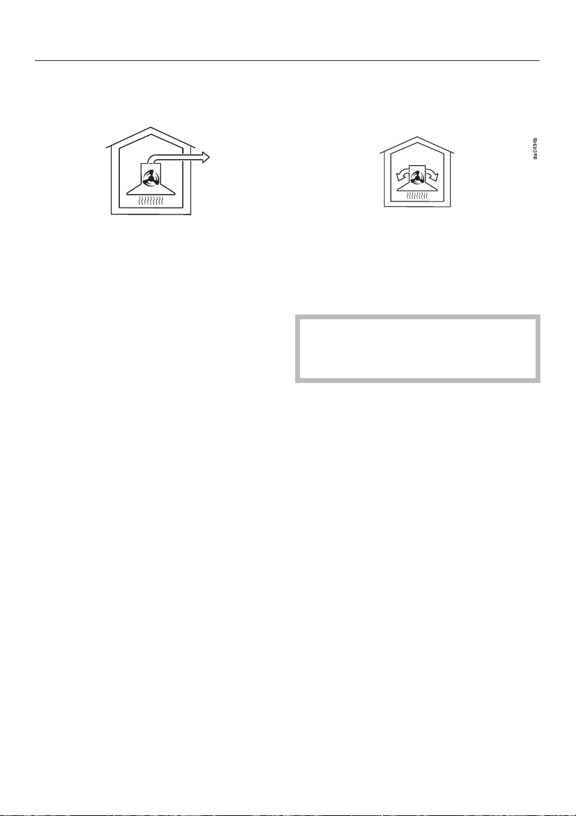
The ventilation system can be operated:
Description of functions
Air extraction
The air is drawn in and cleaned by the
grease filters and directed outside.
The hood comes equipped with a
non-return flap. This flap automatically
closes when the hood is turned off so
that no exchange of outside air and
room air can occur. When the hood is
turned on, the air pressure of the
exhaust fan automatically opens the
flap blowing the inside air and cooking
odors outside.
Recirculation mode
The air is drawn in and cleaned by the
grease filter as well as an odor-free
filter (optional accessories). The
filtered air is then recirculated back into
the kitchen.
In air recirculation mode, please
ensure that the odor-free filter is in
place, see "Cleaning and care".
7
Page 8
Guide to the ventilation system
8
Page 9

Guide to the ventilation system
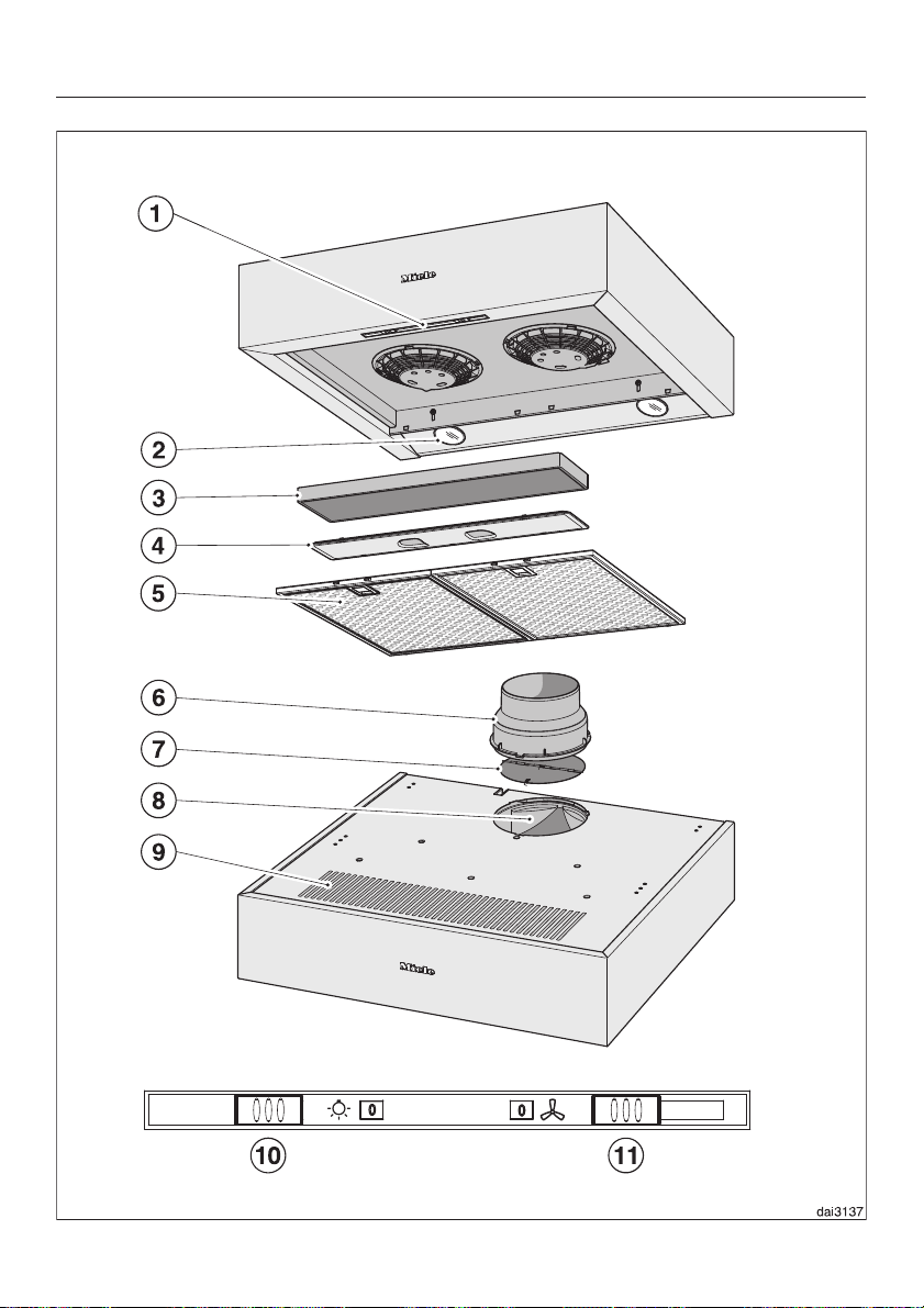
a Control panel
b Overhead lighting
c Odor-free filter (active charcoal
filter)
Optional accessory for recirculation
mode
d Cover for the odor-free filter duct
e Grease filter
f Vent collar C 125 mm or 150 mm
g Non-return flap
h Vent for air extraction
i Recirculation vent
j Switch for the overhead lighting
k Switch for the fan
Turning the light on/off
The overhead light and the fan can be
turned on and off separately j.
"0" – Light off
"1" – Light on
Fan control
This switch k allows you to turn the
^
fan on and off and to select the fan
power level.
"0" – Fan off
^
Levels "1" to "3" are usually sufficient
^
for normal cooking.
^ The "IS" level should be used
temporarily for a short period of time
when frying or cooking food with a
strong aroma.
After cooking
In both air extraction mode and
recirculation mode we recommend that
you run the fan for several minutes after
you have finished cooking.
This helps clear the kitchen air of any
remaining vapors and odors.
9
Page 10
Cleaning and care
,WARNING
TO REDUCE THE RISK OF
FIRE, ELECTRIC SHOCK, OR
INJURY TO PERSONS,
OBSERVE THE FOLLOWING:
Before cleaning or servicing the
hood, disconnect it from the power
supply, see "Important Safety
Instructions".
The halogen bulbs are very hot
,
when in use. They stay hot for some
time after turned off. Use caution,
danger of burns.
Wet cleaning the hot bulbs will
cause damage.
Wait a few minutes after turning
them off before cleaning.
Cleaning the casing
Never use abrasive cleaners,
scouring pads, steel wool or caustic
(oven) cleaners on the hood. They
will damage the surface.
^
All external surfaces and controls can
be cleaned with a mild solution of
warm water and liquid dish soap
applied with a soft sponge.
Avoid:
cleaning agents containing soda,
–
acids or chlorides,
abrasive cleaning agents
–
e.g. powder or cream cleansers,
abrasive sponges, e.g. pot scourers
–
or sponges which have been
previously used with abrasive
cleaning agents.
These will damage the surface.
The following instructions for
–
cleaning "Stainless steel" surfaces
and "Stainless steel colored controls"
should be followed in addition to the
general "Cleaning the casing"
instructions.s.
Stainless steel surfaces
(does not apply to stainless steel
colored controls)
Stainless steel surfaces can be cleaned
using a non-abrasive stainless steel
cleaner.
To help prevent resoiling, a conditioner
for stainless steel can be applied.
^
Wipe dry using a soft cloth.
Do not use too much water when
cleaning the controls. Water could
penetrate the electronics and cause
damage.
10
Page 11

Cleaning and care
Special instructions for appliances
with a colored (RAL) housing.
It is very difficult to clean this type of
surface without causing minor marks on
the surface material.
This can become particularly
noticeable if there is halogen light in the
kitchen.
Stainless steel colored controls
These controls may become discolored
or damaged if not cleaned regularly.
Do not use a stainless steel cleaner on
these controls.
Observe the general cleaning
information in this chapter.
Do not use a stainless steel cleaner
on the controls.
Grease filters
The reusable metal grease filters in the
hood remove solid particles from the
vented kitchen air (grease, dust, etc.)
and prevent soiling of the ventilation
system.
We recommend cleaning the grease
filters every 3-4 weeks, before the
residues solidify.
A dirty filter is a fire hazard!
,
^ Open the grease filter locking clips
and pull the filter down to remove.
To prevent damage to the filter and
the cooktop, hold the filter securely
when handling it.
11
Page 12

Cleaning and care
Cleaning the filter
By hand: use a scrub brush with a
^
solution of warm water and mild
detergent.
Do not use the pure detergent,
aggressive all purpose cleaners,
oven sprays, abrasive cleaning
agents or limescale removers. They
could destroy the filter.
In a dishwasher: place the filter
^
vertically in the lower basket, making
sure that the spray arm is not
blocked.
Use a wash program with a max.
temperature of 150°F (65°C). In a
Miele dishwasher use the "Normal"
program.
Use the recommended amount of
dishwasher detergent. Overuse could
destroy the filter.
Depending on the detergent,
cleaning the grease filter in a
dishwasher may cause permanent
discoloration of the filter surface.
Performance of the filter will not be
affected by this discoloration.
^
After cleaning, the filter can be
placed on a towel to air dry.
^
While the filter is removed, clean any
dirt or grease from the filter casing to
prevent the risk of fire.
12
Page 13
Cleaning and care
Odor-free filter (active charcoal
filter)
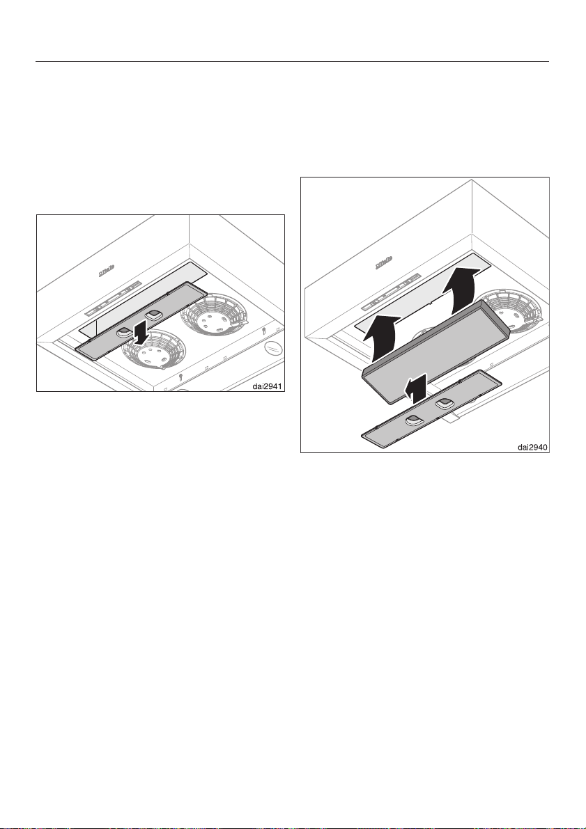
For recirculation mode an odor-free
filter must be used in addition to the
grease filter. The odor-free filter is
designed to absorb cooking odors. It is
inserted above the grease filter.
^ Remove the grease filters.
^ Slide the cover of the odor-free filter
duct slightly to the right and
downward to remove.
Remove the odor-free filter from the
^
packaging.
Insert the odor-free filter into the duct
^
and push upward until it is positioned
under the vent.
^ Reinsert the cover and the grease
filter.
Replace the filter every 6 months or
when it is no longer absorbing cooking
odors.
^
Used odor-free filters may be
discarded with the household waste.
13
Page 14
Cleaning and care
Changing the light bulbs
,WARNING
TO REDUCE THE RISK OF
FIRE, ELECTRIC SHOCK, OR
INJURY TO PERSONS,
OBSERVE THE FOLLOWING:
Before changing the light bulbs,
disconnect the hood from the power
supply, see "Important Safety
Instructions".
When in use halogen bulbs become
extremely hot, and can burn your
hands. Do not attempt to change the
bulbs until they have had sufficient
time to cool.
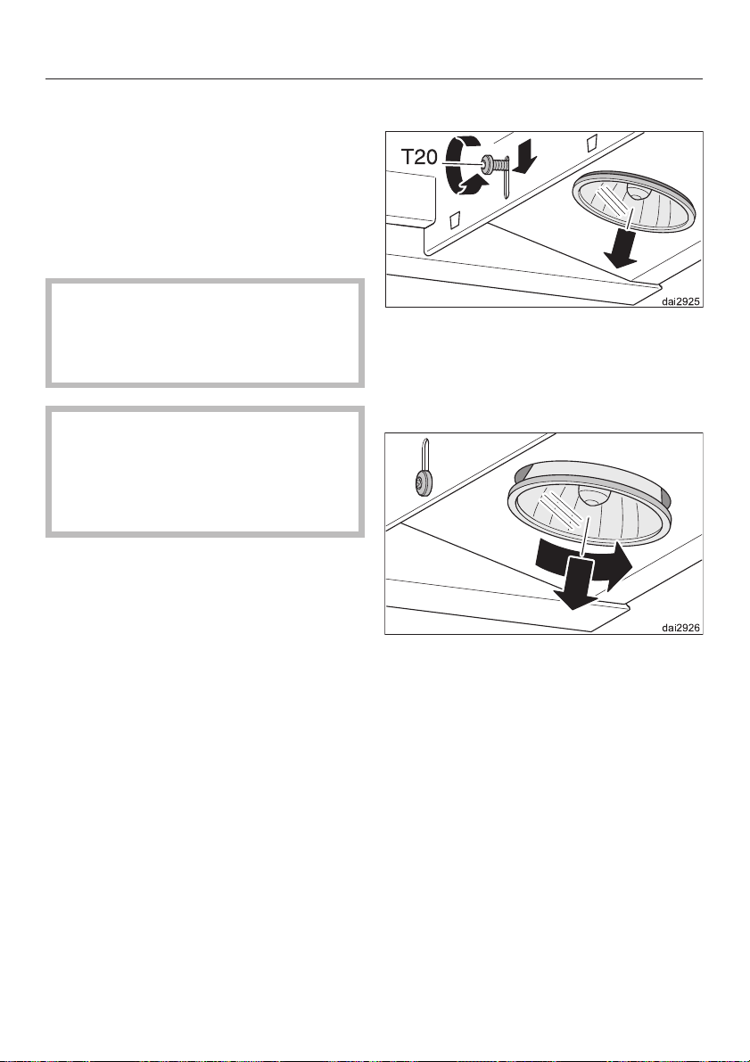
Remove the grease filter.
^
Loosen the light fastening screw
^
slightly.
Slide the screw and the light down.
^
^ Fasten the screw again.
14
^
Turn the light counterclockwise and
pull it out.
Replace it with a light of the same type:
GU/GZ 10, 120 V, 50 W.
^
Install the new light in the reverse
order.
^
Put the grease filter back in place.
Page 15

After Sales Service
Repairs
In the event of a fault which you cannot
easily fix yourself, please contact the
Miele Technical Service Department.
When contacting the Technical Ser
^
vice Department, please quote the
model and serial number of your
appliance.
These are shown on the data plate
which is visible when the grease filter
are removed.
-
MieleCare
(USA only)
MieleCare, our Extended Service
Contract program, gives you the
assurance of knowing that your
appliance investment is covered by
5 years of worry free ownership.
MieleCare is the only Extended Service
Contract in the industry that guarantees
repairs by a Miele Authorized Service
Provider using genuine Miele parts.
Only genuine Miele parts installed by
factory trained professionals can
guarantee the safety, reliability, and
longevity of your Miele appliance.
Please note that unless expressly
approved in writing by Miele’s Service
department, Extended Service
Contracts offered by other providers for
Miele products will not be recognized
by Miele. Our goal is to prevent
unauthorized (and untrained) service
personnel from working on your Miele
products, possibly doing further
damage to them, you and/or your
home.
To learn more about MieleCare
Extended Service Contracts, please
contact your appliance dealer or visit
us online at:
http://mieleusa.com/mielecare
15
Page 16

16
Page 17
Installation Instructions
Read these instructions and the "Important Safety Instructions" before installing
this ventilation system.
The installation steps are described in the enclosed "Installation Diagram".
Leave these instructions with the appliance for the consumer/user.
Information is subject to change. Please refer to our website to obtain the most
current product specification, technical & warranty information.
Page 18

Caring for the environment
Disposal of packing material
The cardboard box and packing
materials protect the appliance during
shipping. They have been designed to
be biodegradable and recyclable.
Please recycle.
DANGER
,
Ensure that any plastic wrappings,
bags, etc., are disposed of safely
and kept out of the reach of babies
and young children. Danger of
suffocation!
Disposal of an old appliance
Old appliances may contain materials
that can be recycled. Please contact
your local recycling center about the
possibility of recycling these materials.
Before discarding an old appliance,
disconnect it from the electrical
supply and cut off the power cord to
prevent it from becoming a hazard.
18
Page 19
Appliance dimensions
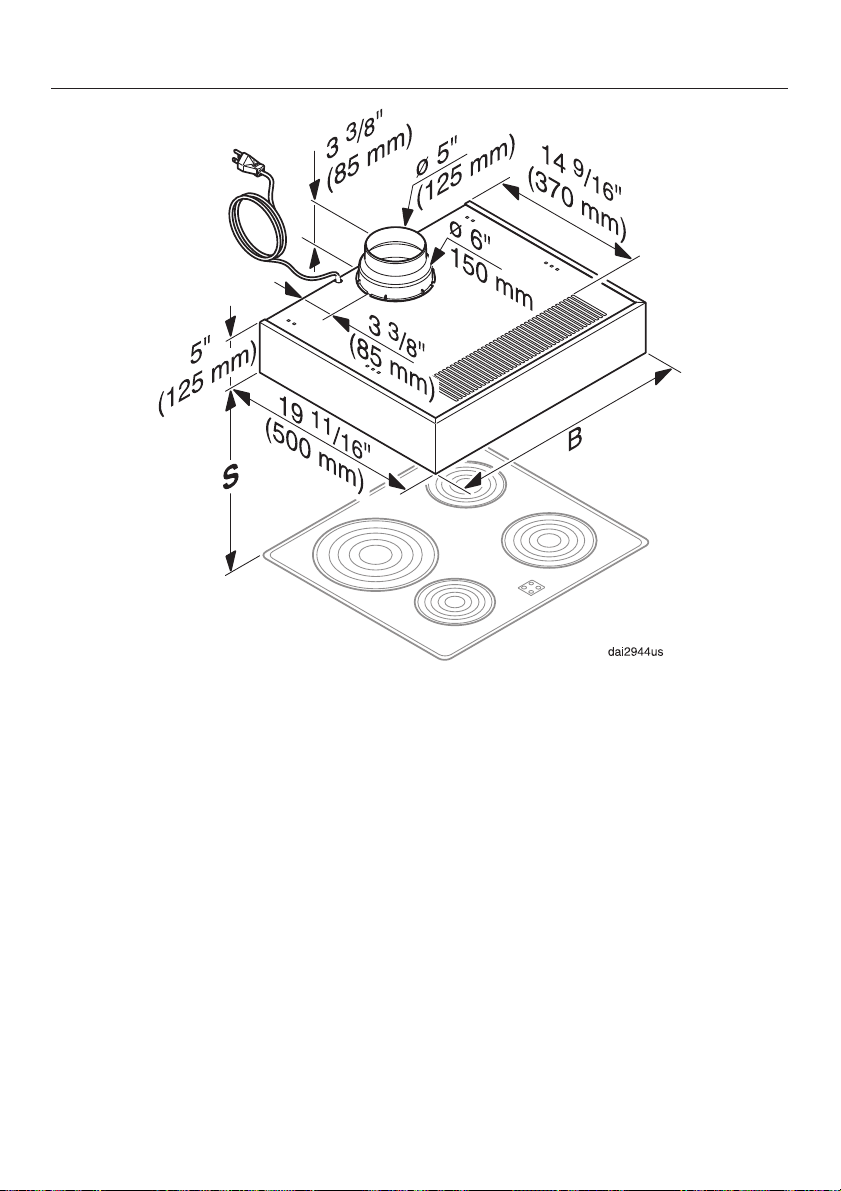
DA 1160 .......B=239/16" (598 mm)
DA 1180 .......B=29
15
/16" (760 mm)
Exhaust connection
–
5" (125 mm) diameter
–
6" (150 mm) diameter
19
Page 20
Appliance dimensions
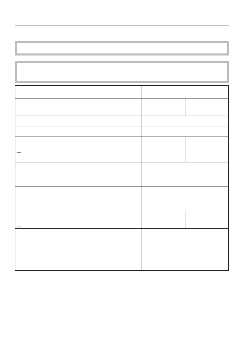
Distance between cooktop and hood (S)
Do not install this exhaust hood over cooktops burning solid fuel.
Provided a larger distance is not given by the manufacturer of the cooktop, follow
the minimum safety distances between a cooktop and the bottom of the hood:
Minimum distance S
Miele
Cooktops
Electric Cooktops 24" (610 mm)
Electric Barbeques and Fryers 26" (660 mm)
Multiburner Gas cooktops
<
43,000 BTU/hr (12.6 KW)
and no burner > 15,000 BTU/hr (4.5 KW)
Multiburner Gas cooktops
73,800 BTU/hr (21.6 KW)
<
and no burner > 16,500 BTU/hr (4.8 KW)
Multiburner Gas cooktops
> 73,800 BTU/hr (21.6 KW)
or one of the burners > 16,500 BTU/hr (4.8 KW)
Single Burner Gas Cooktops
20,500 BTU/hr (6 KW)
<
Single Burner Gas Cooktops
> 20,500 BTU/hr (6 KW)
27,600 BTU/hr (8.1 KW)
<
Single Burner Gas Cooktops
> 27,600 BTU/hr (8.1 KW)
26" (660 mm) 30" (760 mm)
30" (760 mm)
Not possible
26" (660 mm) 30" (760 mm)
30" (760 mm)
Not possible
Non-Miele
Cooktops
–
If several gas surfaces are installed under the hood, the total output must be
considered when determining the minimum safety distance.
–
Be sure to follow the minimum safety distances given by the gas cooktop
manufacturer to easily flammable materials e.g. upper cabinets.
20
Page 21

Appliance dimensions
If local building codes require a greater safety distance, follow their requirement.
–
If there is more than one appliance beneath the hood and they have different
–
minimum safety distances always select the greater distance.
See "Important Safety Instructions" for further information.Also see the "Important
Safety Instructions" section.
To ensure free access to work under the ventilation hood, a distance of a
–
minimum of 26" (660 mm) above the electric cooktop is also recommended.
21
Page 22
Installation
Before installation read the
information in the "Appliance
Dimensions" and " Important Safety
Instruction" chapters.
This is especially crucial when using
the ventilation system at the same
time as another heat-producing
appliance that uses air from the
same room.
Remove the grease filter.
^
The casing of stainless steel models is
covered with a protective film to
prevent scratching during transport.
^ Remove the film from the casing and
from the grease filter frames before
installing. It can be removed without
tools.
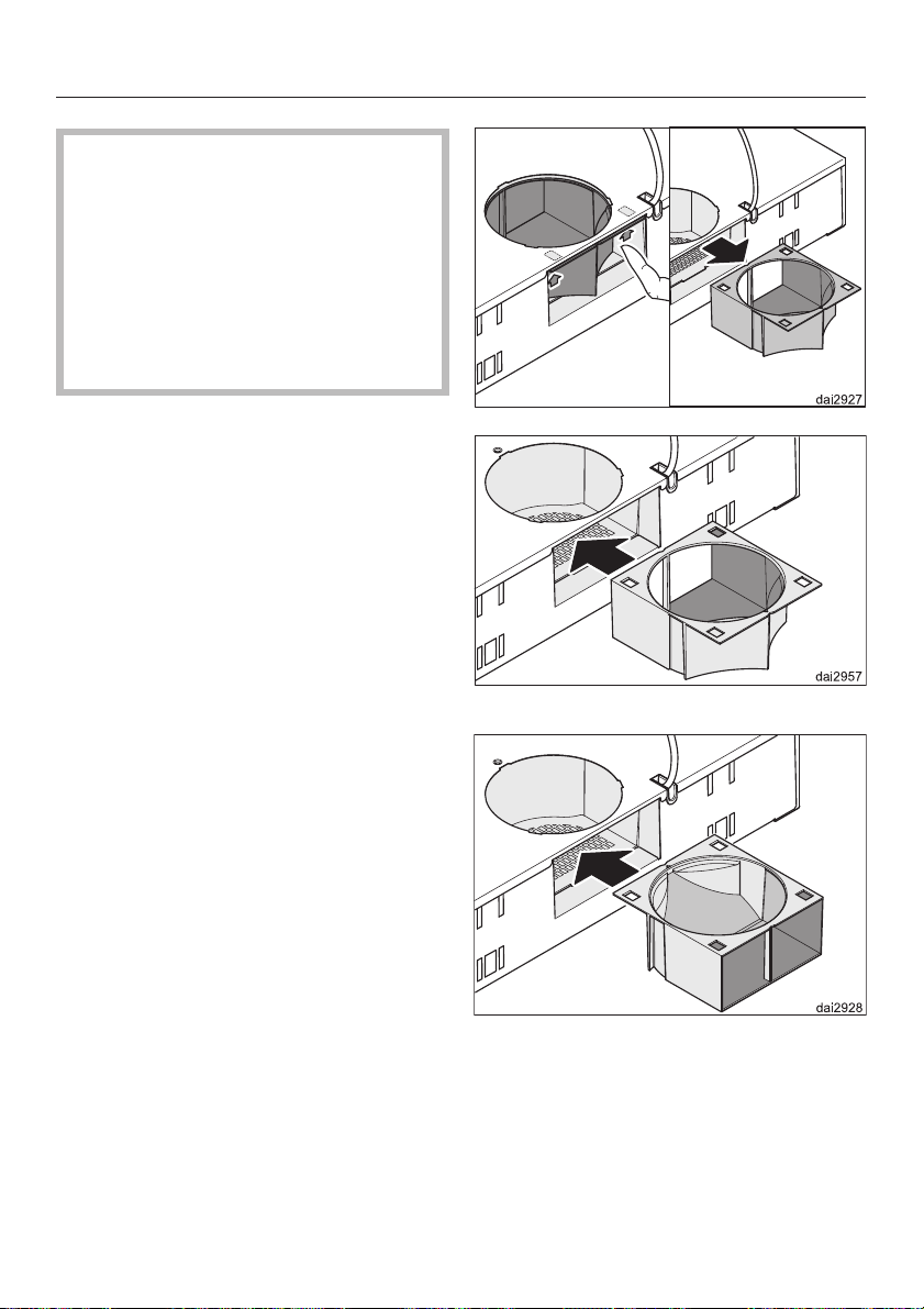
Diverter
A diverter must be inserted at the back
of the hood.
Its position depends on the operating
mode.
In air extraction mode, it guides the air
outside through an opening at the back
of the casing.
In air recirculation mode, it closes the
opening and guides the air to the outlet
at the front.
^
Check the position of the diverter.
^
If required, change the diverter
position to match the desired
operating mode.
22
Extraction
Recirculation
^
To do this, push on the two latching
hooks, pull the diverter out, turn it,
and push it back in until it clicks into
place.
Page 23
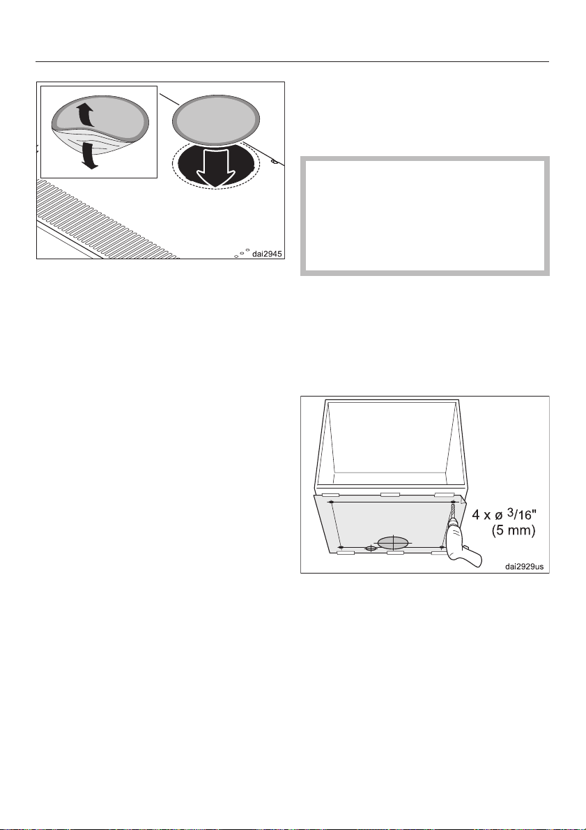
For operation in recirculation mode,
^
cover the opening at the back with
the sticker.
The sticker comes with the odor-free
filter which is available as an optional
accessory (active charcoal filter).
Installation
Under-cabinet installation
Several holes for fastening the device
under a cabinet are provided in the top
of the casing.
Use only the holes on the drill
,
template. Use only the specified
screws. Faulty installation can
damage the ventilation system and
impair the electrical safety (e.g.
electric shocks).
If using the recirculation mode with a
very deep cabinet it must be ensured
that the cabinet does not cover the
recirculation air outlet.
^ Fasten the cut-out drill template to
the bottom of the cabinet.
^
Drill four mounting holes C
through the bottom of the cabinet.
3
/16"(5mm)
23
Page 24
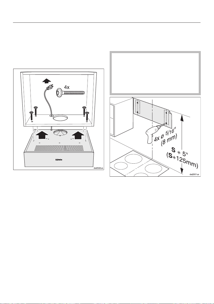
Installation
For extraction mode you must also
^
drill a 6
the bottom of the cabinet.
If you want to lay the power cord
^
though the cabinet you must drill a
hole for it, too.
^ Lift the hood up under the cabinet
and feed the power cord through the
respective hole in the bottom of the
cabinet.
^
From the inside of the cabinet, fasten
the hood to the cabinet using the
screws provided.
^
Put the grease filter back in place.
3
/4" (170 mm) hole through
Wall mounting
You can also mount the device to a wall
using the two wall anchors.
The screws and dowels are
,
suitable for solid brick walls.
For other types of walls, use
appropriate materials.
Make sure that the wall can support
the weight.
^
Fasten the cut-out drill template to
the wall. The template's upper edge
marks the upper edge of the hood.
Observe the safety clearance (S) to
the cooktop (see "Appliance
dimensions").
^
Mark and drill the four holes
(C 8 mm) for the wall anchors.
24
^
Remove the drill template.
Page 25
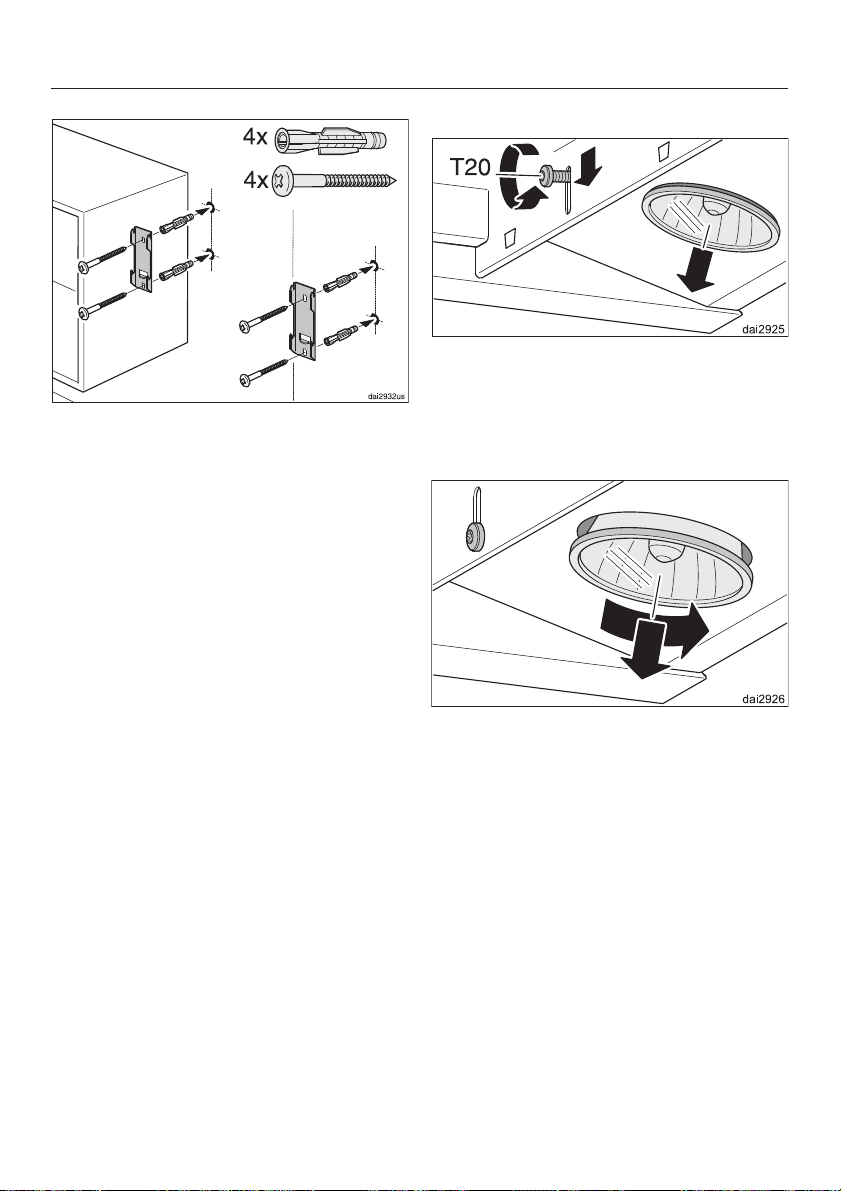
Fasten the wall anchors to the wall
^
using the dowels and screws
provided.
Installation
Remove the overhead lights.
^
Slightly loosen the light fastening
^
screw.
Slide the screw and the light down.
^
Fasten the screw again.
^
^
Turn the light counterclockwise and
pull it out.
25
Page 26
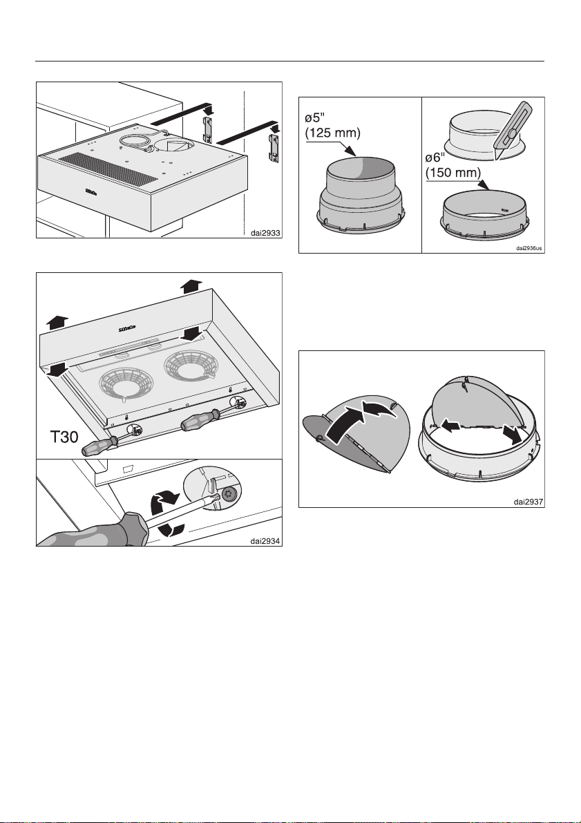
Installation
Attach the hood to the wall anchors.
^
For air extraction mode:
For an C 6" (150 mm) exhaust duct,
^
use a pointed knife to cut off the
exhaust collar where it tapers.
For an C 5" (125 mm) exhaust duct,
use the collar as is.
^
Tighten the two screws at the left and
the right on the back of the device.
These are used to adjust the tilt and
secure the hood in position.
^
Reinstall the overhead lights.
^
Put the grease filter back in place.
^
If extraction mode is used, install the
exhaust ducting and connections.
26
^
If required, insert the non-return flap.
Ensure that the flap opens easily and
closes by itself.
Page 27
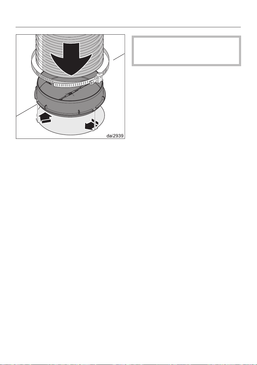
^ Fasten the exhaust duct to the
exhaust collar e.g. using a flexible
duct and a clamp (optional
accessory).
^ Insert the exhaust collar into the
exhaust opening and secure it by
turning it clockwise.
Installation
Observe the instructions in
"Important safety instructions" and
"Electrical connection".
Plug the power cord into the power
^
outlet.
To carry out a function test, turn the
^
fan on.
In extraction mode, no air should
–
come out of the air outlet at the front
of the hood.
In recirculation mode, the air should
–
come out of the air outlet at the front
of the hood.
If this is not the case, the diverter in not
installed correctly (see "Diverter").
^ For further exhaust ducting see
"Exhaust ducting".
For recirculation mode:
^
Insert the odor-free filter (see
"Cleaning and care").
27
Page 28

Electrical connection
,WARNING
TO REDUCE THE RISK OF
FIRE, ELECTRIC SHOCK, OR
INJURY TO PERSONS,
OBSERVE THE FOLLOWING:
All electrical work should be
performed by a qualified electrician
in strict accordance with national
regulations (for USA: ANSI-NFPA
70) and local safety regulations.
Installation, repairs and other work
by unqualified persons could be
dangerous.
Ensure that power to the appliance
is OFF while installation or repair
work is performed.
^ Verify that the voltage, load and
circuit rating information found on the
data plate (located behind the
grease filter), match the household
electrical supply before installing the
hood.
^
Use only with ventilation hood
cord-connection kits that have been
investigated and found acceptable
for use with this model hood.
Grounding Instructions
This appliance must be grounded. In
the event of an electrical short circuit,
grounding reduces the risk of electric
shock by providing a path of least
resistance. This appliance is equipped
with a cord having a grounding wire
with a grounding plug. The plug must
be plugged into an outlet that is
properly installed and grounded.
WARNING - Improper grounding can
result in a risk of electric shock.
If there is any doubt, have the electrical
system of the house checked by a
qualified electrician.
Do not use an extension cord. If the
power supply cord is too short, have a
qualified electrician install an outlet
near the appliance.
Important
The hood comes equipped with a 2.5 ft
(0.75 m) power cord with a NEMA 5-15
molded plug for connection to a
120 VAC, 60 Hz, 15 A power outlet.
If there is any question concerning the
electrical connection of this appliance
to your power supply, please consult a
licensed electrician or call Miele’s
Technical Service Department.
,WARNING:
THIS APPLIANCE MUST BE
GROUNDED
28
Page 29

WARNING
,
Danger of toxic fumes.
Gas cooking appliances release
carbon monoxide that can be
harmful or fatal if inhaled.
To reduce the risk of fire and to
properly exhaust air, the exhaust
gases extracted by the hood
should be vented outside of the
building only.
Do not vent exhaust air into
spaces within walls or ceilings or
in attics, crawl spaces or garages.
Exhaust ducting
Use smooth or flexible pipework made
from approved non-flammable
materials for exhaust ducting.
To achieve the most efficient air
extraction and quietest noise levels,
consider the following:
The diameter of the ductwork should
–
not be less than 6" (150 mm).
If flat ducting is used, the cross
–
section must not be smaller than the
cross section of the ventilation
exhaust.
The ducting should be as short and
–
straight as possible.
– Use ductwork with a wide radius.
To reduce the risk of fire, only use
metal ductwork.
Please read and follow the
"IMPORTANT SAFETY
INSTRUCTIONS" to reduce the risk of
personal injury. Follow all local building
codes when installing the hood.
– The exhaust duct must not be bent
or compressed.
– Make sure all connections are
secure.
– Where the ductwork is horizontal, it
must slope away from the hood at
1
least
/8" per foot (1 cm per meter) to
prevent condensation dripping into
the appliance.
–
If the exhaust is ducted through an
outside wall, a Telescopic Wall Vent
can be used (optional accessory).
29
Page 30
Exhaust ducting
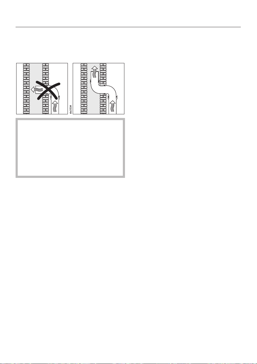
If the exhaust is ducted into an
–
inactive flue, the air must be expelled
parallel to the flow direction of the
flue.
Never connect an exhaust hood to
an active chimney, dryer vent, flue,
or room venting ductwork. Seek
professional advice before
connecting an exhaust hood vent to
an existing, inactive chimney or vent
flue.
Important!
If the ductwork runs through rooms,
ceilings, garages, etc. where
temperature variations exist, it may
need to be insulated to reduce
condensation.
30
Page 31
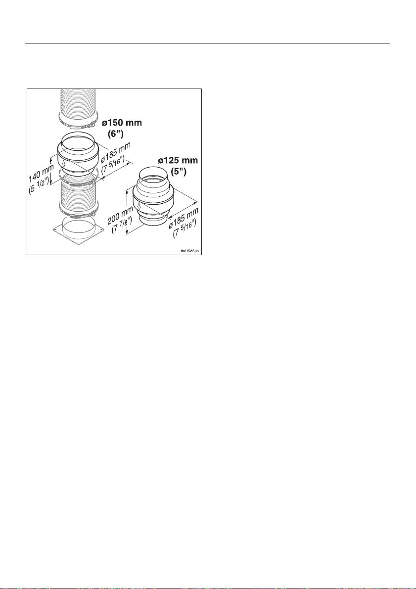
Condensate trap
(optional accessory)
In addition to appropriate insulation of
the exhaust ducting, we recommend
installing a condensate trap to collect
and evaporate any condensation which
may develop. This is available for ducts
C 5" ( 125 mm) or C 6" ( 150 mm).
Exhaust ducting
When installing a condensate trap,
ensure that it is positioned vertically
and if possible directly above the
exhaust outlet of the ventilation hood.
The arrow on the casing indicates the
exhaust flow direction.
31
Page 32

Technical data
DA 1160, DA 1180
Maximum load ...............380W
Fan motor...............2x140W
Overhead lights ...........2x50W
Voltage .................... 120V
Frequency ..................60Hz
Fuse rating ...................15A
Length of the
power cord ...........2.5ft(0.75 m)
Weight
DA 1160...........24.7 lbs (11.2 kg)
DA 1180...........28.4 lbs (12.9 kg)
Required for recirculation mode:
1 x odor-free filter: Miele DKF18-1
active charcoal filter
323334
Page 33

Page 34

Page 35

35
Page 36

DA 1160
DA 1180
M.-Nr. 10 296 060 / 00en-US
 Loading...