

Page 1
-
Style G
midmark.com
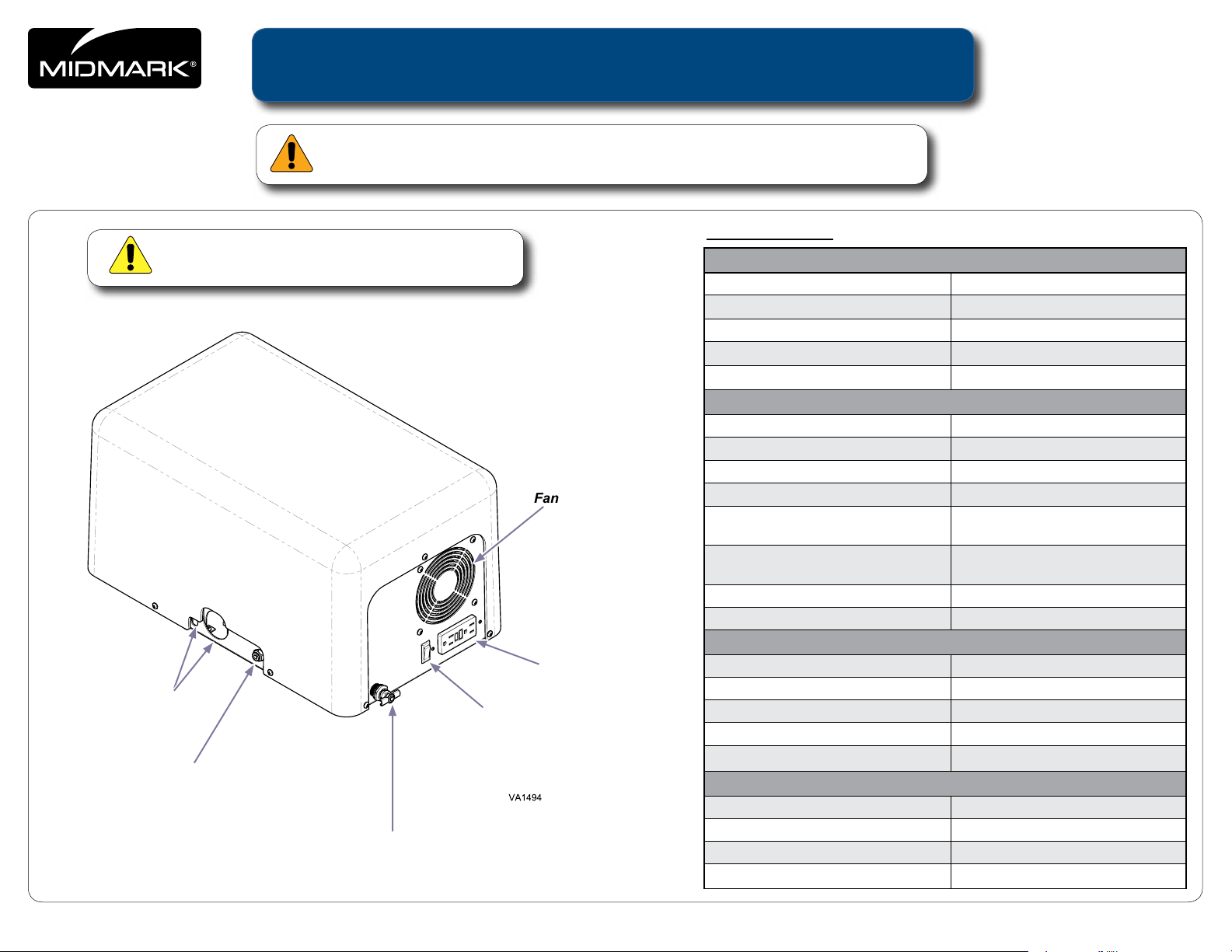
Use caution when lifting Solo unit. Solo weighs 54 lbs.
Umbilical & Foot
Control Cord
Entry
City Water Inlet
Connection
Caution
VetPro® Solo Installation
WARNING
Equipment is not suitable for use in the presence of a flammable anesthetic mixture.
Specications
Shipping Weight 61 lbs ( 27.7 kg)
Frequency 60 Hz
Circuit Breaker Protection 15 amps
Fan
Accessory Outlet (Side Mounted,
Accessory Outlet
On / Off Switch
Drain Valve
Hospital Grade Wiring NEMA type: 14 and 18 AWG
User Specs)
Receptacles (Internal) NEMA Outlet, Snap AC Connector,
Power Cord Length 5 ft. NEMA 5-15R
Working Pressure 80 - 100 PSI
Sound Level (full load) < 55 dB
Water Connection
Water Inlet Length 10 ft. (3 m)
Water Inlet Thread Size 3/8” FNPT
Saddle Valve Adapter Length 2 ft. (.61 m)
Saddle Clamp Range
Dimensions
Width 12.75 inches (32.4 cm)
Length 20.89 inches (53 cm)
Height 11.40 inches (29 cm)
Weight 54 lbs ( 24.5 kg)
Electrical
Voltage 115 VAC
GFCI 5 amps, 125 VAC
15 amp, 125 VAC
Plug 15 amps, 125 VAC
Compressor
Motor Oil Free 1/3 HP
Flow Rate 2.6 scfm @ 45 PSI
Air Tank 1 gal 3.79 Liter
5/16
3/8” - 1
” OD Copper Pipe
© 2011 Midmark Corp. | 60 Vista Drive Versailles, OH 45380 USA | 1-800-643-6275 | 1-937-526-3662 |
1
003-1996-00 Rev. E 2/2/16
Page 2
-
Important Information
Intended Use
To provide Midmark VetPro® 5000 Wall, Cabinet and Table Mount Dental Delivery System with compressed air, water and electrical power.
Electromagnetic Interference
Safety Symbols
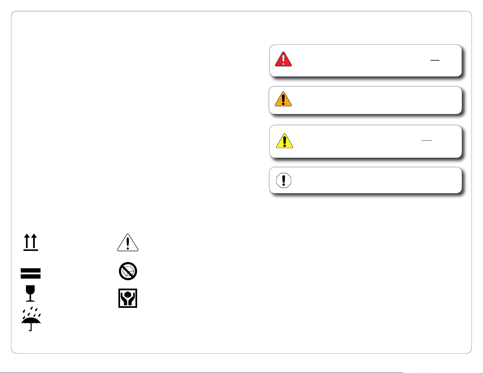
DANGER
Indicates an imminently hazardous situation which will result
in serious or fatal injury. This symbol is used only in the
most extreme conditions.
The VetPro® Solo is designed and built to minimize electromagnetic interference with other devices.
However, if interference is noticed between another device and this product:
• Removeinterferingdevicefromroom
• PlugVetPro® Solo into isolated circuit
• IncreaseseparationbetweenVetPro
• ContactMidmarkifinterferencepersists
®
Solo and interfering device
Disposal of Equipment
At the end of product life, accessories, and other consumable goods may become
contaminated from normal use. Consult local codes and ordinances for proper disposal of
equipment, accessories and other consumable goods.
Transportation / Storage Conditions
Ambient Temperature Range:................0°F to 140°F (-18°C to +60°C)
Relative Humidity...................................10% to 90% (non-condensing)
Atmospheric Pressure...........................700hPa (20 in.Hg) to 1060hPa (31 in.Hg)
Proper Shipping
Orientation
Consult User Guide
3
Maximum stacking
height (3 High)
Do Not Tumble
WARNING
Indicates a potentially hazardous situation which could result
in serious injury.
Caution
Indicates a potentially hazardous situation which may result in
minor or moderate injury. It may also be used to alert against
unsafe practices
Equipment Alert
Indicates a potentially hazardous situation which could result in
equipment damage.
Fragile
Keep Dry
Handle With Care
2
Page 3
-
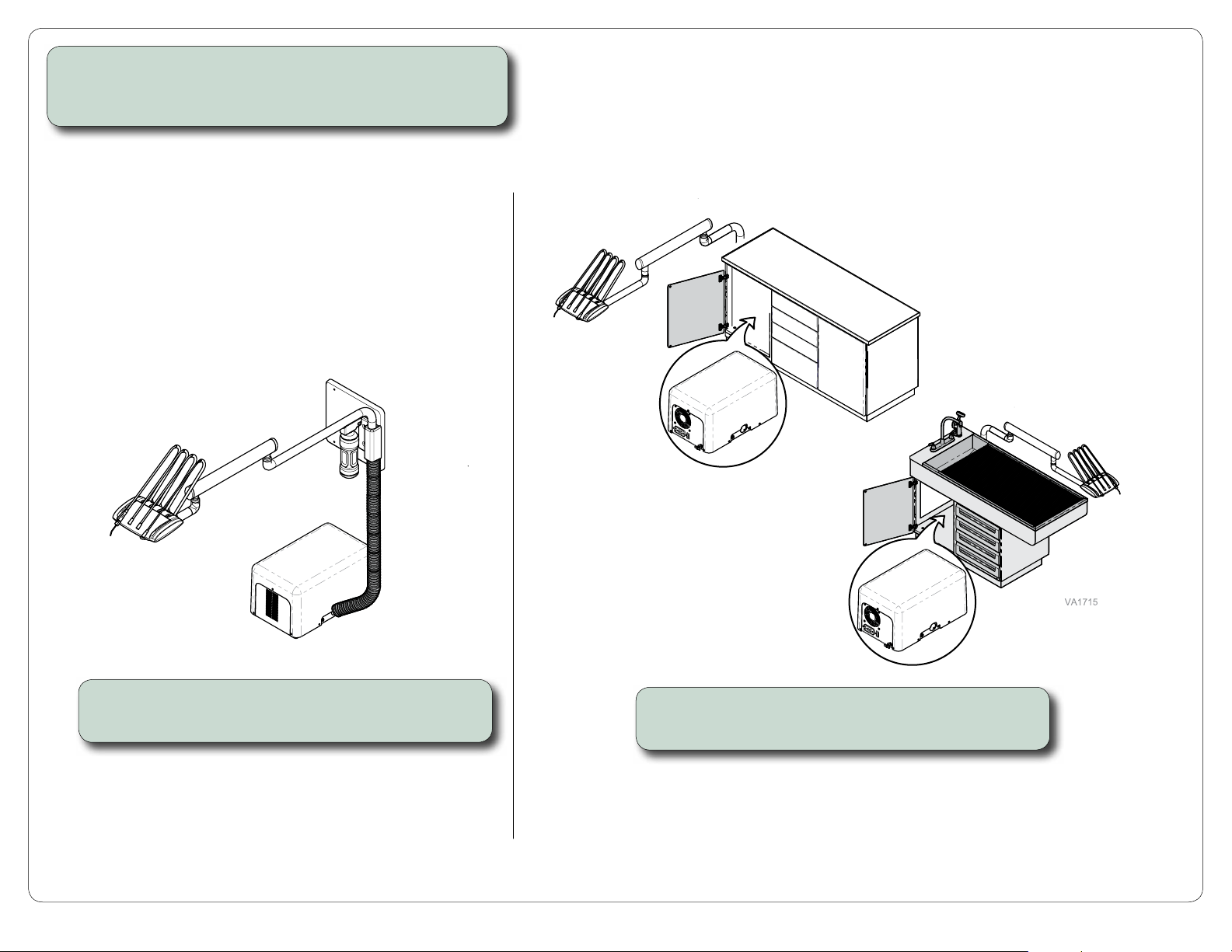
Before you install...
A) Remove VetPro
B) Determine placement of Solo unit, then follow instructions.
®
Solo from packaging.
Floor Installation
Cabinet / Table Installation
If installing VetPro Solo to wall mount...
Go to page 4 for installation procedure.
If installing VetPro Solo in cabinet / table...
Go to page 6 for installation procedure.
3
Page 4
-
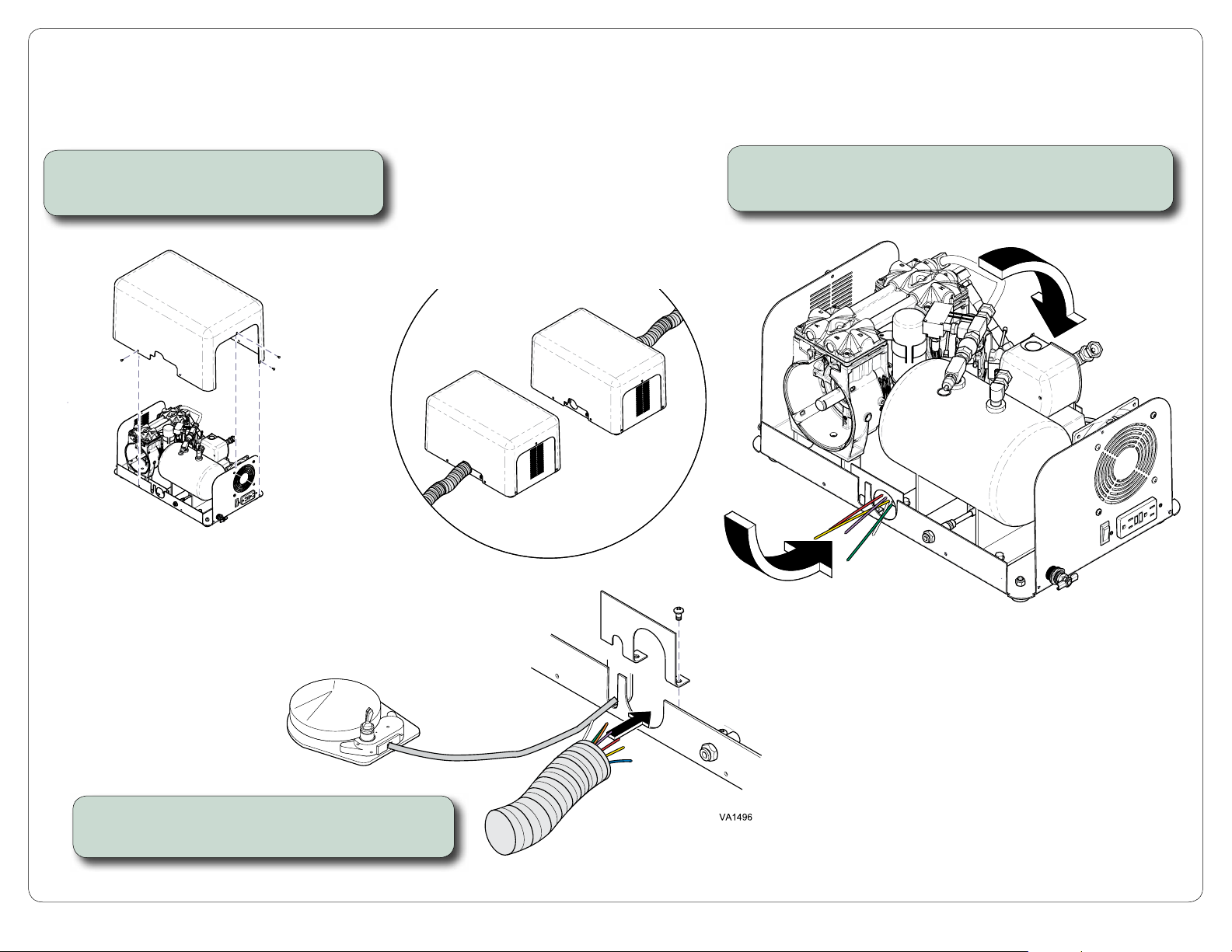
Floor Installation
Step 1: Remove VetPro Solo cover.
A) Remove screws & outer cover as shown.
To connect umbilical to the opposite side of Solo...
A) Re-route tubing to the other side of the Solo unit.
Determine the desired position
of the umbilical...
Step 2: Remove umbilical clamp.
A) Remove umbilical clamp from appropriate side.
4
Page 5
-
Color Page
Floor Installation - continued
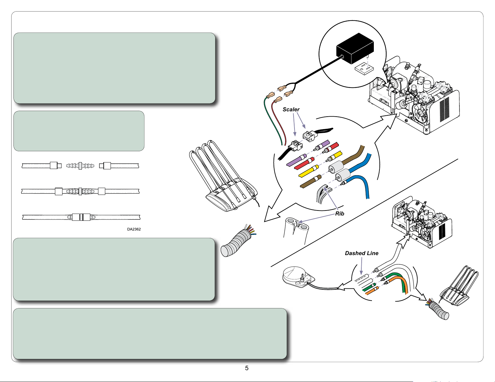
Step 3: Connect VetPro tubing / wiring to Solo.
A) Connect red & green wires to fiber optic power supply.
B) Plug fiber optic power supply into receptacle inside of Solo.
C) Connect scaler wiring.
D) Slide uni-clamps onto purple, red, & yellow tubing from umbilical,
then connect to matching colors from Solo.
Note: Fiber Optics are optional.
To Connect Tubing..
A) Slide uni-clamp onto tubing.
B) Slide tubing onto barbed fitting.
C) Slide uni-clamp over the barbed fitting.
Fiber Optic
Power Supply (Optional)
Scaler
Step 4: Connect water bottle tubing.
A) Slide uni-clamps onto brown tubing from water bottle,
then connect to valve / brown tubing from Solo.
B) Pull grey water bottle tubing apart to separate two sections.
C) Locate ribbed section of water bottle tubing.
D) Connect ribbed section to valve / blue tubing from Solo.
E) Connect non-ribbed section to blue tubing from umbilical.
Step 5: Connect foot control tubing.
A) Connect clear tubing with dashed line from foot control to clear tubing from Solo.
B) Connect clear tubing from foot control to clear tubing from umbilical.
C) Slide uni-clamps onto green & orange tubing from foot control, then connect to matching
colors from umbilical. Brown tube from from foot control is not used.
Rib
Dashed Line
VA1717-1i
5
Page 6
-
Color Page
Cabinet / Table Installation
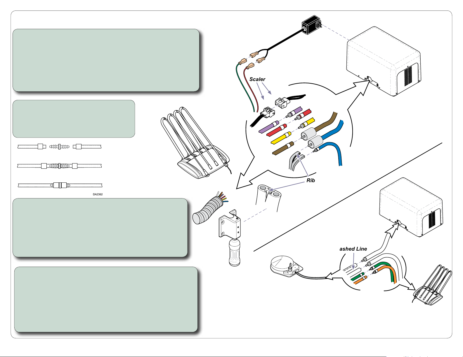
Step 2: Connect VetPro® tubing / wiring to Solo.
A) Connect red & green wires to fiber optic power supply.
B) Plug fiber optic power supply into receptacle on back of Solo.
C) Connect scaler wiring.
D) Slide uni-clamps onto purple, red, & yellow tubing from VetPro®,
then connect to matching colors from Solo.
Note: Fiber Optics are optional.
To Connect Tubing..
A) Slide uni-clamp onto tubing.
B) Slide tubing onto barbed fitting.
C) Slide uni-clamp over the barbed fitting.
Fiber Optic
Power Supply (Optional)
Scaler
Rib
Step 3: Connect water bottle tubing.
A) Slide uni-clamps onto brown tubing from water bottle,
then connect to valve / brown tubing from Solo.
B) Pull grey water bottle tubing apart to separate two sections.
C) Locate ribbed section of water bottle tubing.
D) Connect ribbed section to valve / blue tubing from Solo.
E) Connect non-ribbed section to blue tubing from VetPro.
Step 4: Connect foot control tubing.
A) Connect clear tubing with dashed line from foot control to
clear tubing from Solo.
B) Connect clear tubing from foot control to clear tubing from
VetPro.
C) Slide uni-clamps onto green & orange tubing from foot control,
then connect to matching colors from VetPro. Brown tube from
foot control will not be used.
Dashed Line
VA1712-1i
6
Page 7
-
-
Cabinet / Table
Installation - continued
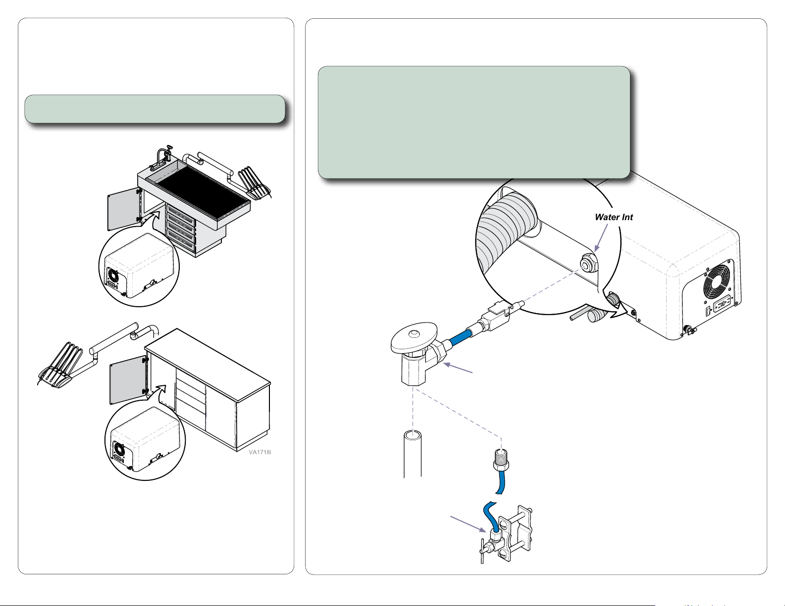
Step 5: Position VetPro Solo in cabinet / table.
City Water Supply Connection without Saddle Valve
(Refer to following page for connection using the saddle valve)
Note: This is an optional conection if facility water is desired.
Connect shut-off valve assembly to water supply.
A) Replace Solo cover.
B) Disconnect shut-off valve from saddle valve / tubing assembly.
C) Connect shut-off valve to facility water supply according to
local codes / regulations.
D) Insert quick connector into Solo water intake as shown.
Water Intake
VA1497
Saddle Valve
7
Shut-off Valve
Page 8
-
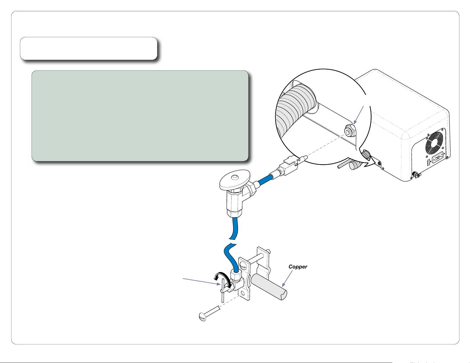
City Water Supply Connection with Saddle Valve
Note
This is an optional hook-up if facility water is desired.
Connect shut-off valve using saddle valve.
A) Replace Solo cover.
B) Turn valve handle counterclockwise to fully retract valve pin.
C) Remove one screw from saddle valve clamp, then
position clamp around copper tubing.
D) Tighten screws firmly to secure clamp.
(Note: Tighten screws alternately to keep clamps parallel).
E) Turn handle clockwise until until you feel valve pin puncture copper tubing.
F) Turn handle counterclockwise to open valve.
G) Adjust flow using shut-off valve.
H) Insert quick connector into Solo water intake as shown.
Shut-off Valve
Water Intake
VA1545
Handle
Copper Tubing
8
 Loading...