

Page 1
TP202 20-42-FO-00014 Rev A1 C2169
003-1879-99 Rev. WA1 (2/7/18)
Style P
User’s Guide
VetPro® 1000
Mobile Dental
Delivery System
For Models:
8000-001
8000-002
8000-003
8000-004
8000-005
8000-006
8000-006S
8000-007
8000-007S
8000-008
8000-008S
English
Español
Français
Page 2
© Midmark Corporation 2016
English - 2
TP202 20-42-FO-00014 Rev A1 C2169
003-1879-99
Product Information
(The information below is required when calling for service.)
Model / Serial Number:
Date of Purchase:
Midmark Authorized Service
Company:
Dealer :
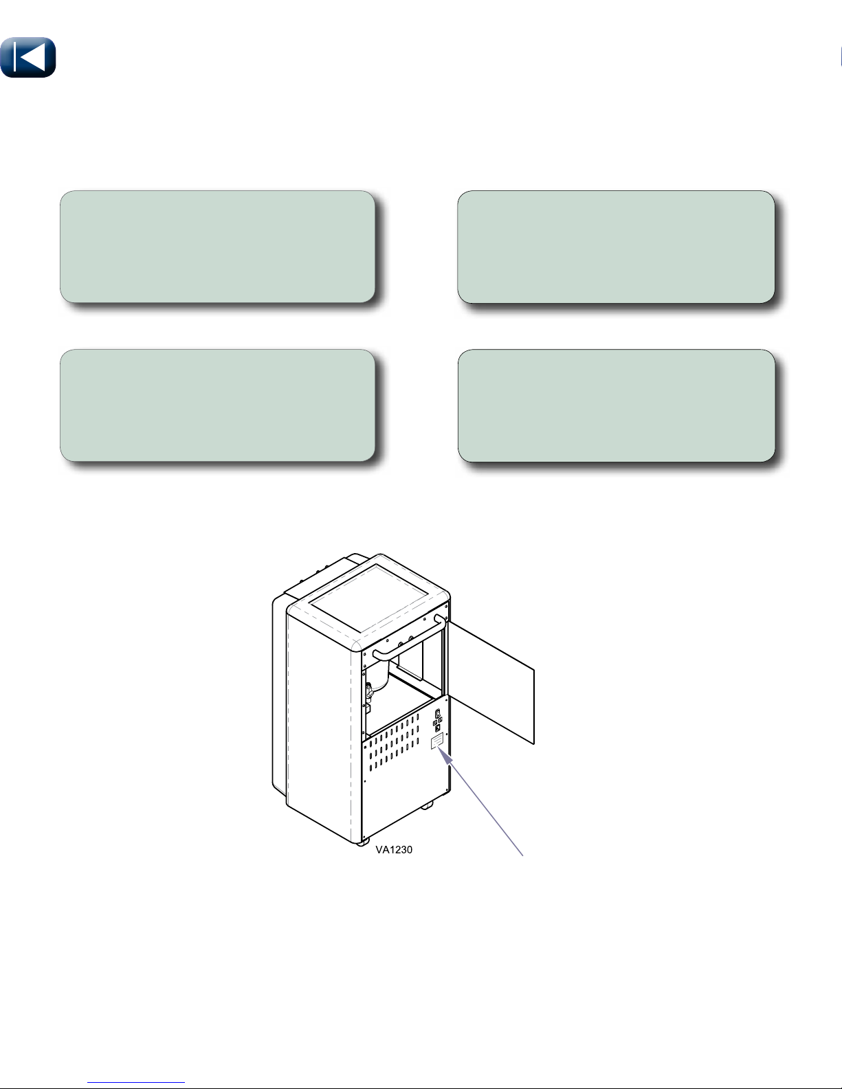
Model / Serial Number Location
Page 3

© Midmark Corporation 2016
English - 3
TP202 20-42-FO-00014 Rev A1 C2169
003-1879-99
Table of Contents
Important Information
Safety Symbols....................................................................................................................4
Intended Use .......................................................................................................................5
Electromagnetic Interference...............................................................................................5
Disposal of Equipment.........................................................................................................5
Authorized EU Representative ............................................................................................ 5
Transportation / Storage / Operating Conditions .................................................................5
Transport
Transporting Dental System ................................................................................................6
Operation
Electrical System ................................................................................................................. 7
Water System ......................................................................................................................8
Air System ...........................................................................................................................9
Delivery System...................................................................................................................10
Handpiece Care...................................................................................................................11
Syringe Tip Replacement & Handpeice Installation.............................................................12
Drive Air Adjustment & Locking Casters .............................................................................. 13
Air Pressure Regulator & Water Flow Adjustment ............................................................... 14
Coolant Air Adjustment ........................................................................................................ 15
Cleaning / Maintenance
Cleaning ..............................................................................................................................16
Maintenance ........................................................................................................................ 18
Calling for Service ...............................................................................................................22
Specifications
Drawing ...............................................................................................................................23
Weights / Dimensions .......................................................................................................... 24
Electrical .............................................................................................................................. 25
Model Identification / Compliance Chart ..............................................................................26
Warranty
Warranty Information ...........................................................................................................27
For installation information go to:
Technical Library at Midmark.com
Page 4
© Midmark Corporation 2016
English - 4
TP202 20-42-FO-00014 Rev A1 C2169
003-1879-99
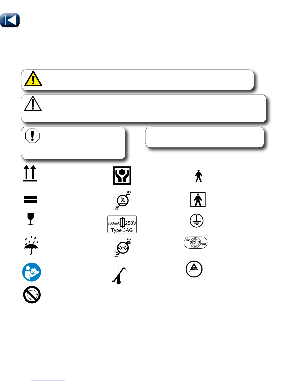
Type B, Applied Part
Temperature Limit
Handle With Care
Humidity Limit
Fuse Rating
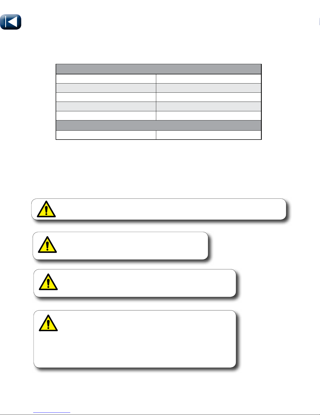
Specifications
Pressure Limit
Safety Symbols
Important Information
Proper Shipping
Orientation
Maximum stacking
height
(Do not stack)
Fragile
Keep Dry
Refer to Instruction
Manual/Booklet
WARNING
Indicates a potentially hazardous situation which could result in serious injury.
Caution
Indicates a potentially hazardous situation which may result in minor or moderate injury. It may
also be used to alert against unsafe practices.
Equipment Alert
Indicates a potentially hazardous
situation which could result in equipment
damage if not avoided.
Note
Ampliesaprocedure,practice,orcondition.
Type BF, Applied Part
Protective Earth Ground
LED Scaler Handpiece
Duty Cycle
US
C
TUVRheinland
TUV - Domestic
Models Only
Do Not Tumble
100 F
38 C
23 F
-5 C
Page 5

© Midmark Corporation 2016
English - 5
TP202 20-42-FO-00014 Rev A1 C2169
003-1879-99
Disposal of Equipment
At the end of product life, the unit(s), accessories, and other consumable goods may be
contaminated from normal use. Consult local codes and ordinances for proper disposal of
equipment and other consumable goods.
Authorized CE Representative
Countries in the EEC should direct all questions, incidents, and complaints to Midmark’s Authorized CE
representative listed below:
Midmark EMEA Ltd
Beech House
First Floor, East Wing
Ancells Business Park
Fleet
Hampshire GU51 2UN
United Kingdom
Tel: + 44 (0) 1252 360 940
Fax: + 44 (0) 1252 360 941
Transportation / Storage / Operating Conditions
Transportation / Storage Temperature Range: .......................................23°F to 100°F (-5°C to 38°C)
Operating Temperature Range: .............................................................. 50°F to 104°F (+10°C to +40°C)
Transportation / Storage Relative Humidity: ........................................... 10% to 90% (non-condensing)
Operating Relative Humidity: .................................................................. 30% to 75% (non-condensing)
Transportation / Storage Atmospheric Pressure:....................................50 kPA (7.2 psi) to 106 kPA (15.3 psi)
Operating Atmospheric Pressure:...................................................700 hPA (20 in Hg) to 1060 hPA (31 in Hg)
Intended Use
The Midmark® VetPro® 1000 is a mobile dental delivery system intended to give qualified veterinarians
and/or technicians a self-contained, compact, portable unit for performing veterinary dental procedures.
Electromagnetic Interference
This product is designed and built to minimize electromagnetic interference with other devices.
However, if interference is noticed between another device and this cart:
•Removeinterferingdevicefromroom
•Plugcartintoanisolatedcircuit
•IncreaseseparationbetweenMidmarkproductandinterferingdevice
•ContactMidmarkifinterferencepersists
Page 6

© Midmark Corporation 2016
English - 6
TP202 20-42-FO-00014 Rev A1 C2169
003-1879-99
Transport
WARNING
Exercise care when transporting over thresholds and other low lying objects.
Failure to do so can lead to injury.
Threshold
When transporting over large thresholds or steps...
A) Pull cart up and over onto level surface.
Page 7
© Midmark Corporation 2016
English - 7
TP202 20-42-FO-00014 Rev A1 C2169
003-1879-99
6
A
M
P
6
A
M
P
VA1227
Operation
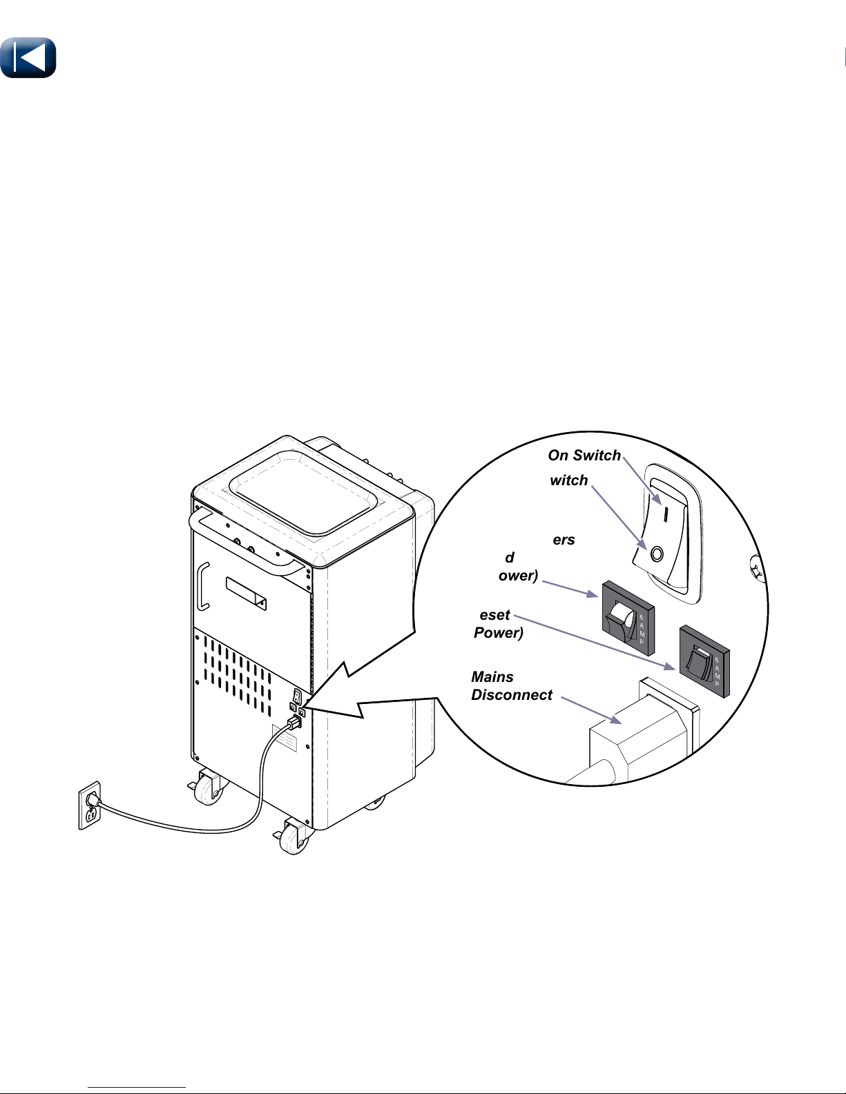
Electrical System
On/Off Switch
On/Off Switch is located on the back of the cart. It controls the main power source and must be ON to
operate the delivery system.
Circuit Breakers
There are two circuit breakers located on the lower back panel of the cart. If the unit’s maximum load is
exceeded, the circuit breakers interrupt power to the unit. Maximum load is 115 VAC, 6 amps (domestic)
230 VAC, 3 amps (export).
Mains Disconnect
Power can be terminated by unplugging the mains disconnect or turning switch off.
(O) Off Switch
( I ) On Switch
Circuit Breakers
Tripped
(No Power)
Mains
Disconnect
Reset
(Power)
Page 8
© Midmark Corporation 2016
English - 8
TP202 20-42-FO-00014 Rev A1 C2169
003-1879-99
VA1229
Operation
Water System
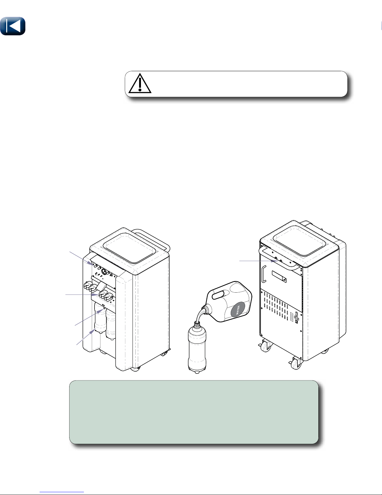
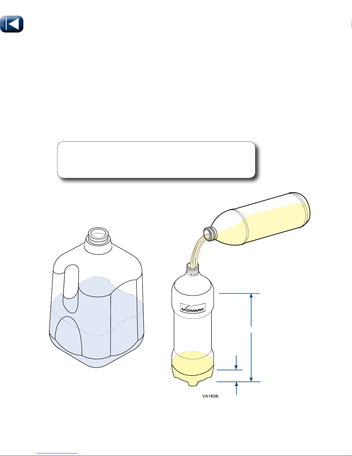
Water Bottles
The unit has two 1 liter bottles. The water bottles supply water to the handpieces, air/water syringe and a
quick disconnect on the back of the cart. Air flows through the water regulator and the toggle switch to the
water bottles. The water system is regulated to 40 PSI. Use the water needle valve to adjust water flow
for each instrument. The toggle switch between the water bottles that controls which bottle will supply the
water. When the toggle is in the center neither water bottle is pressurized. Move the toggle toward the
left to pressurize the left bottle and depressurize the right bottle. Toggle to the right to pressurize the right
bottle and depressurize the left bottle.
Toggle
To fill water bottles...
A) Move toggle to center.
B) Remove water bottle and fill. (Distilled Water Is Recommended)
C) Replace water bottle and move toggle toward filled water bottle.
Note: Water bottles should be checked in between each patient and filled if necessary.
Water Quick Disconnect
The water quick disconnect has a blue ring. You can attach accessories to the cart that will utilize the
water from the cart. You may need to add a regulator if attaching equipment that can not handle 40 PSI.
Water
Needle
Valve
Water
Regulator
Water
Bottles
Water Quick
Disconnect
Caution
Failure to properly seal water bottles can lead to patient injury.
Page 9
© Midmark Corporation 2016
English - 9
TP202 20-42-FO-00014 Rev A1 C2169
003-1879-99
VA1231
Operation
Air System
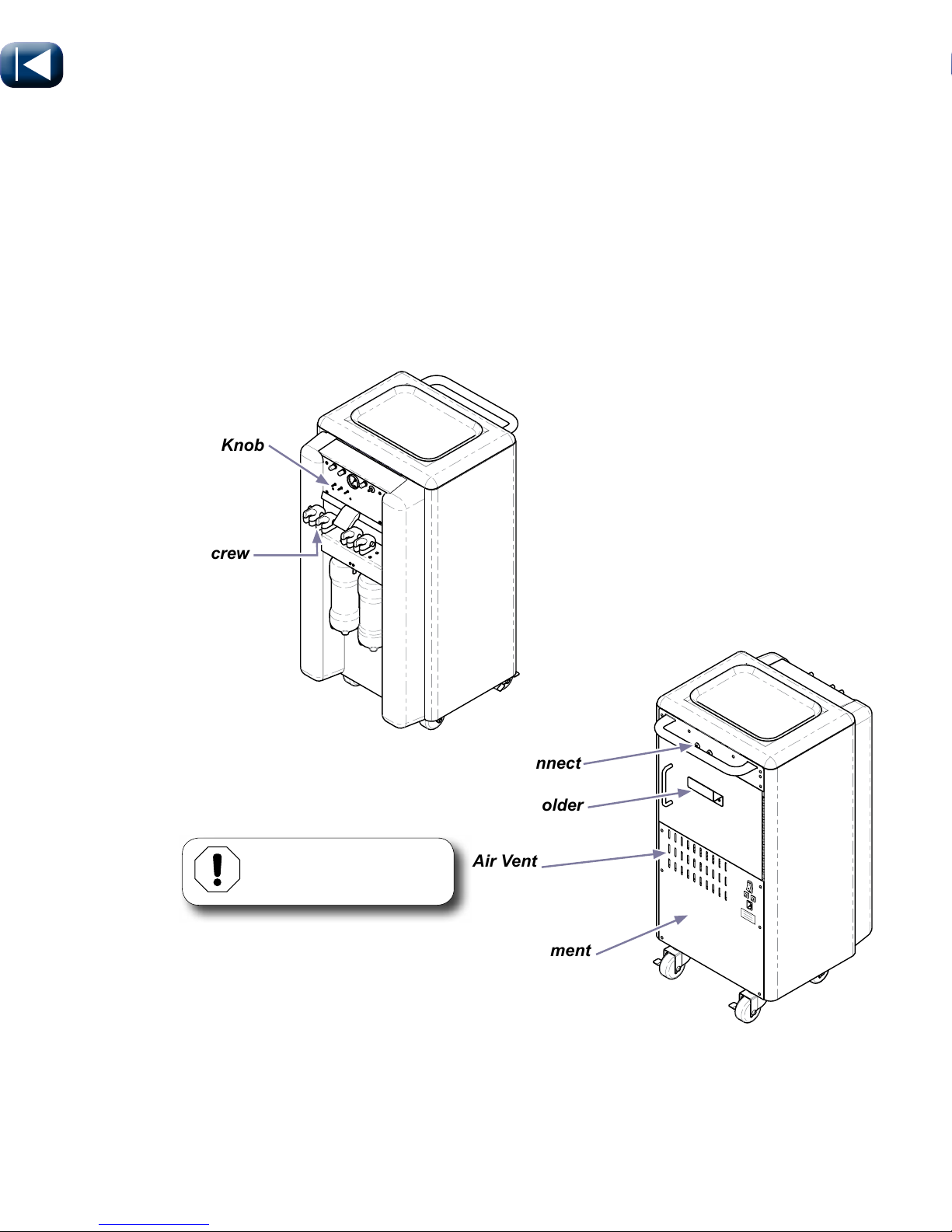
Compressor
The air system is a 1/3 HP compressor with a 2 liter air tank and regulator. It supplies air for the
handpieces, air/water syringe, and a quick disconnect on the back of the cart. The compressor will cycle
between 70 to 100 PSI. The regulator is factory set at 65 PSI.
Air Quick Disconnect
The air quick disconnect has a red ring. You can attach accessories to the cart that will utilize the air from
the cart. You may need to add a regulator if attaching equipment that can not handle 100 PSI.
Coolant Air
Adjustment Screw
Drive Air
Adjustment Knob
Air Quick Disconnect
Air Vent
Compressor Compartment
Foot Control Holder
Equipment Alert
Do not block air vent.
Page 10
© Midmark Corporation 2016
English - 10
TP202 20-42-FO-00014 Rev A1 C2169
003-1879-99
VA1233
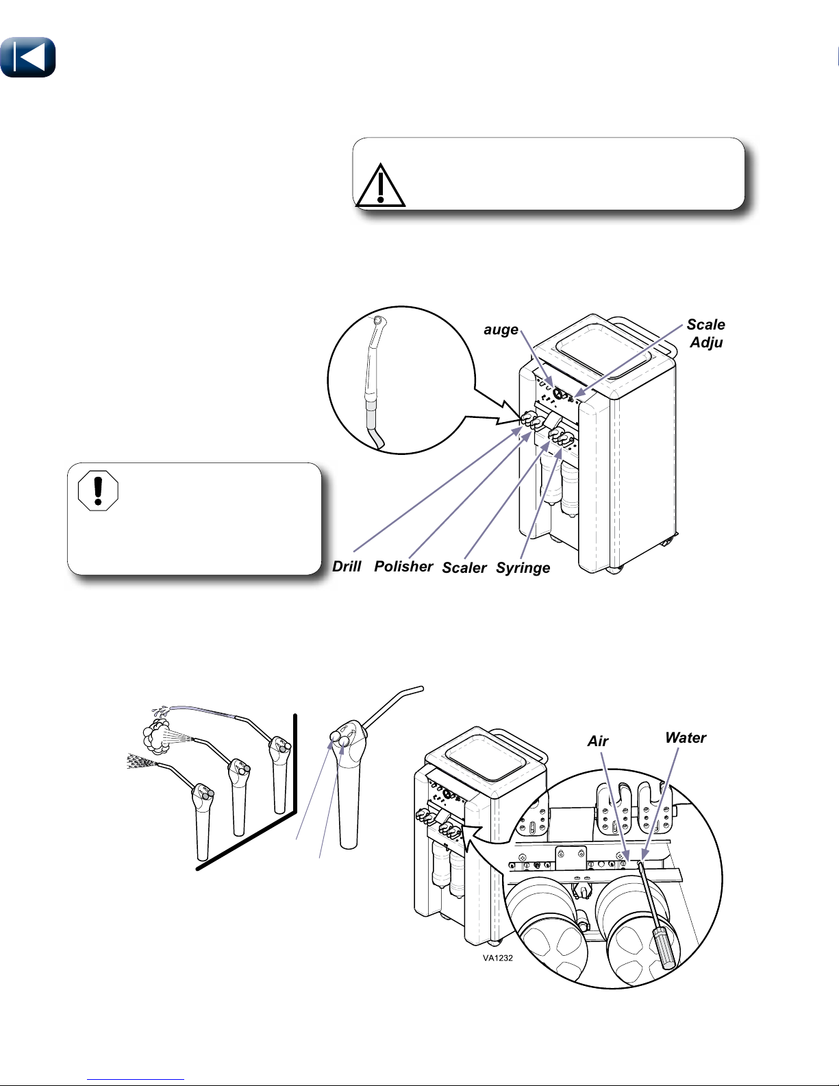
Handpieces
The delivery system controls up to four handpieces. The handpiece pressure is controlled by handpiece
drive air adjustment valves. The gauge on front of the delivery system indicates the handpiece pressure.
Handpiece pressure should not exceed 60 PSI under normal operation. The scaler tool (optional) has an
adjustment knob for the intensity level.
Operation
Delivery System
Air/Water Syringe
There are air and water buttons on top of the syringe. When both buttons are depressed you will get a
mist of both water and air. Air and water adjustments are located under the syringe holder. Insert flat head
screwdriver into adjustment screw(s). Counter-Clockwise to increase flow and Clockwise to decrease flow.
Turn screw until desired air/water flow is coming through the instrument.
Gauge
Air
Water
Equipment Alert
Refer to handpiece
manufacturer for suggested PSI
settings. Only check one handpiece
at a time.
Handpiece
Holders
Scaler
Adjustment
Air
Water
Caution
Handpieces and Syringe Tip should be changed
or disinfected between each patient.
Drill Polisher
Syringe
Scaler
Page 11
© Midmark Corporation 2016
English - 11
TP202 20-42-FO-00014 Rev A1 C2169
003-1879-99
Operation
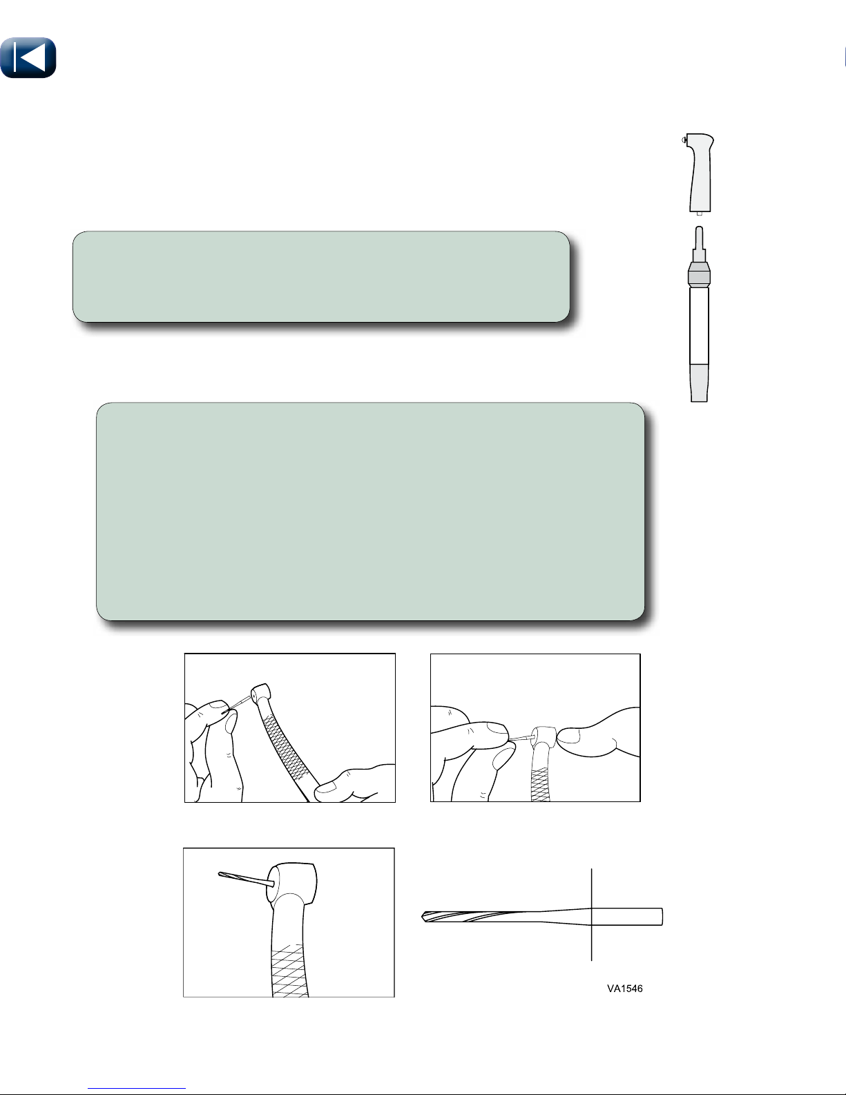
To Change Bur in High Speed Handpiece...
A) Push button on back of handpiece and pull the bur out.
B) Push bur into handpiece. (The shank will only go in half-way)
C) Then push button on back of handpiece and push the bur in until
shank is all the way in.
Note: Friction grip burs (FG Style) are designed so that the entire straight portion of
the shaft should be inside the chuck of the handpiece. You should only see the tapered
portion of the bur if installed properly. New bur recommended for each procedure.
Prophy
Angle
Prophy Angle Replacement
To Change Prophy Angle...
A) Rotate chuck to the right to unlock.
B) Install Prophy angle, turn chuck release ring left to tighten.
Push
Button
Push Bur Into Handpiece
Finish Sliding Bur Into
Handpiece
Shaft Inside Handpiece
This Portion of
the Bur Should
be Inside the
Handpiece
Burr Replacement
Page 12
© Midmark Corporation 2016
English - 12
TP202 20-42-FO-00014 Rev A1 C2169
003-1879-99
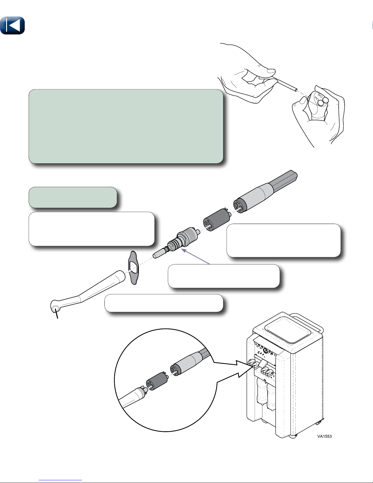
Handpiece Installation
VA1807i
To Change Syring Tip...
A) Press down on large collar.
B) When a soft “click is felt pull tip straight out.
C) Hold collar down and insert new tip. Be sure to
press it all the way in, then release collar.
D) Test the installation by giving a firm pull on tip, to
assure it is inserted all the way and locked in place.
Syringe Tip Replacement
Install handpieces.
Line up components properly to
prevent damage resulting in hand
piece failure.
Lightly spray the exposed o-rings
with one step conditioner.
Tighten coupler firmly with wrench.
Handpiece
Connection
Swivel Coupler
Connection
Note
Not all units will be equipped with lamp
module.
Page 13
© Midmark Corporation 2016
English - 13
TP202 20-42-FO-00014 Rev A1 C2169
003-1879-99
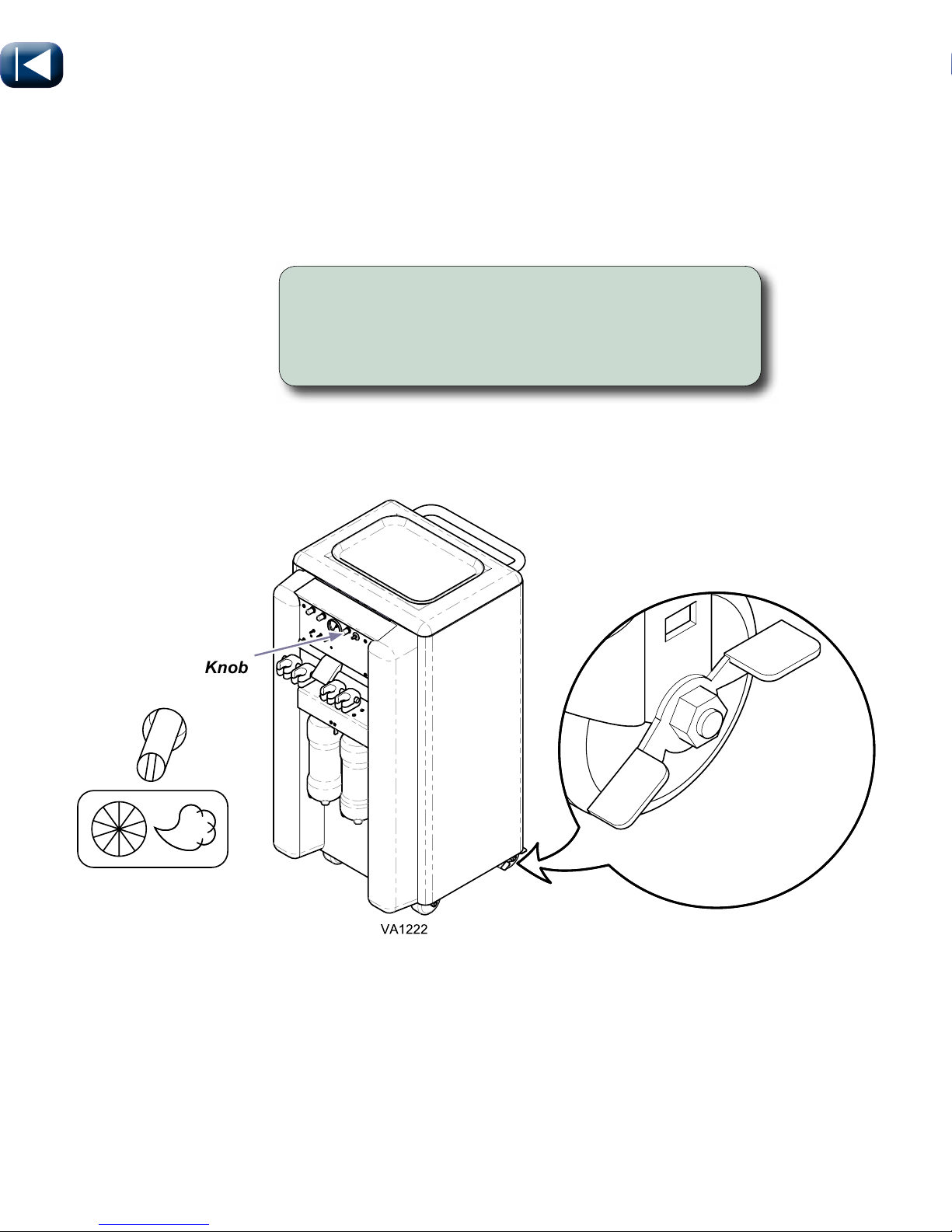
Drive Air Adjustment
& Locking Casters
Drive Air
Adjustment Knob
To adjust drive air...
Insert flat head screwdriver into knob for Drive Air
Adjustment (for desired handpiece). Turn knob until
proper air pressure displays on the pressure gauge.
OFF for Unlock
ON for Lock
Page 14
© Midmark Corporation 2016
English - 14
TP202 20-42-FO-00014 Rev A1 C2169
003-1879-99
Operation
Decrease
Increase
Adjustment
Knob
Unlock
Lock
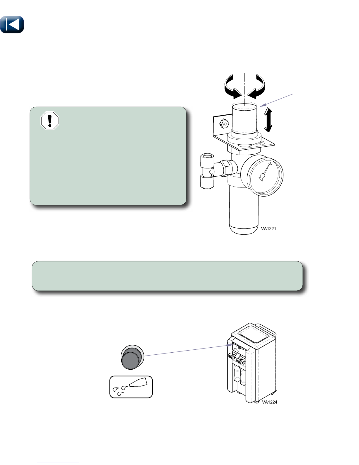
Air Pressure Regulator Adjustment
EQUIPMENT ALERT
Do not adjust regulator over
65 PSI.
To Adjust Regulator...
A) Pull adjustment knob upward to unlock.
B) Rotate adjustment knob clockwise to
increase pressure, counterclockwise to
decrease pressure.
C) Push adjustment knob downward to lock.
To adjust water flow...
Rotate Water Needle Valve (for desired handpiece) until desired flow is achieved.
Water Needle Valve
Water Flow Adjustment
Page 15
© Midmark Corporation 2016
English - 15
TP202 20-42-FO-00014 Rev A1 C2169
003-1879-99
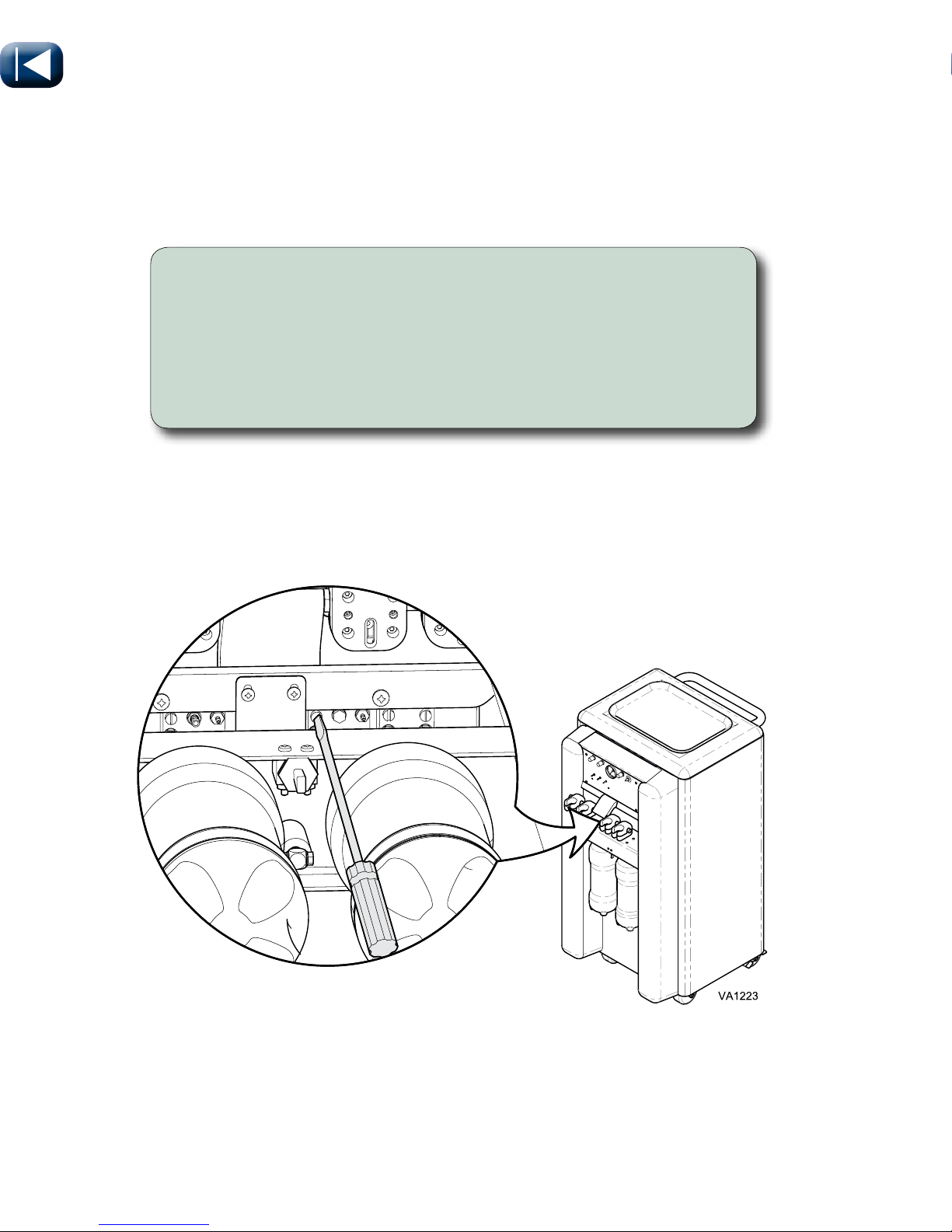
Operation
To adjust coolant air...
Insert flat head screwdriver into knob for Coolant Air Adjustment
(for desired handpiece). Counter-Clockwise to increase flow and
Clockwise to decrease flow. Turn screw until desired air pressure is
coming through the instrument.
Note: Drive air adjustment screws are located below tool holders for each instrument.
Coolant Air
Adjustment Screws
Coolant Air Adjustment
Page 16
© Midmark Corporation 2016
English - 16
TP202 20-42-FO-00014 Rev A1 C2169
003-1879-99
Note:
Use only 5.25% Bleach Solution. Do not use bleach with
scents, color guards, or other additives. Mix fresh every day.
~90%
~10%
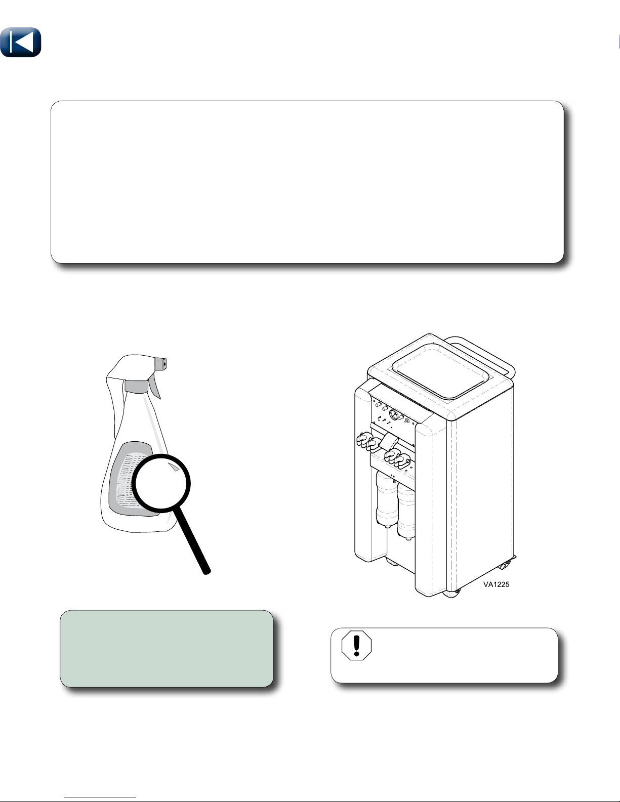
Cleaning
•Usecleanersthatareappropriateforthesituation,suchaswarmwaterandmilddetergents,
or a 10% solution of bleach with 90% water.
•Cleantheexteriorsurfaceswithaclean,lintfreecloth,dampenedwithdisinfectant.Donot
drip any liquid into open vents, plugs or connectors. Dry the surfaces with a clean cloth or
paper towel.
•Aftercleaning,visuallyinspecttheproductfordeteriorationofcovers.Donotusethedelivery
system if excessive discoloration, cracking, or other signs of wear are noticeable (See Calling
for Service instructions).
Page 17
© Midmark Corporation 2016
English - 17
TP202 20-42-FO-00014 Rev A1 C2169
003-1879-99
Note
Every veterinary practice setting is different and no one disinfectant is the best choice for every
facility. There are several organizations educated in disinfection procedures. Refer to web sites of
accredited sources that can assist veterinary personnel in choosing what is best for
their practice. Listed below are a few of the sites.
Organization for Safety & Asepsis Procedures
http://www.osap.org
Dept. of Health & Human Resources Centers for Disease Control & Prevention (CDC)
http://www.cdc.gov
When using disinfectants...
• Carefully read the product label
and directions for use.
• Do not exceed the dilution rate.
DA148100i
Read
carefully
Equipment Alert
Refer to handpiece manufacturer
for suggested cleaning procedures.
Cleaning continued...
Page 18

© Midmark Corporation 2016
English - 18
TP202 20-42-FO-00014 Rev A1 C2169
003-1879-99
Maintenance
At the beginning of each work day...
• Fill water bottles with fresh distilled water.
• Flush handpieces.
Between each patient...
• Remove disposable tips,
instruments, etc..
• Flush delivery system.
• Disinfect handpieces and scaler
per manufacturers instructions.
• Disinfect syringe tip.
• Fill water bottles.
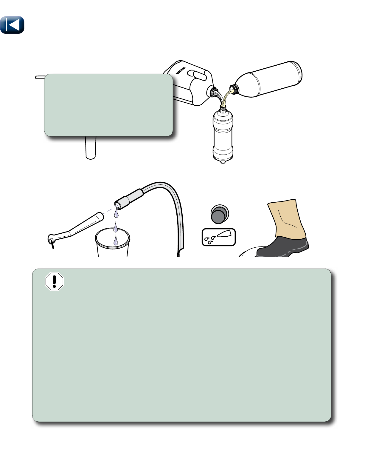
To Flush Delivery System..
A) Remove all handpieces that use water.
B) Open water needle valve.
C) Hold end of tubing over a container and depress foot control.
D) Allow water to run 20 to 30 seconds.
E) Install newly disinfected handpieces and syringe tip.
F) Refill water bottle.
Water Needle Valve
Note
Distilled water is not mandatory.
However, water must meet
requirements for drinking.
Equipment Alert
AUTOCLAVABLE SYRINGE TIP STERILIZATION
The autoclavable syringe tips supplied with the delivery system
must be sterilized prior to use with each patient, including initial use. Be sure to
thoroughly rinse and clean syringe tips prior to sterilization, any debris may reduce
the effectiveness of the sterilization. Recommended sterilization process is steam
autoclave. Recommended parameters are 125°C (250°F) and 106 kPa (15 PSI) for 40
minutes at temperature and pressure.
Equipment Alert
HANDPIECE STERILIZATION
Between each procedure complete
manufacture’s instructions for “Infection Control /
Sterilization found in the documentation included
with the handpieces. Failure to do this will cause
premature failure of handpieces.
Page 19
© Midmark Corporation 2016
English - 19
TP202 20-42-FO-00014 Rev A1 C2169
003-1879-99
BLEACH
Maintenance continued...
At the end of each day...
• Bleach flush delivery system and
empty water system.
• Drain air regulator.
• Drain condensation from air tank.
• Clean system.
EQUIPMENT ALERT
Do not use colored/scented bleach, or concentrations greater than
recommended. Do not leave bleach solution in delivery system longer than
30 minutes, it could damage the delivery system.
To Bleach Flush Delivery System..
A) Remove all handpieces that use water.
B) Remove water bottles and fill with 9 parts water and 1 part bleach.
C) Open water needle valve.
D) Hold end of tubing over a container and depress foot control.
E) Allow water to run 20 to 30 seconds.
F) Leave bleach solution in delivery system for 10 - 20 minutes, then
remove / empty / rinse water bottles.
G) Fill water bottles with fresh water and repeat steps C thru E until bleach odor is gone.
H) Install newly disinfected handpieces and syringe tip.
I) Empty water bottles.
Page 20
© Midmark Corporation 2016
English - 20
TP202 20-42-FO-00014 Rev A1 C2169
003-1879-99
VA1238
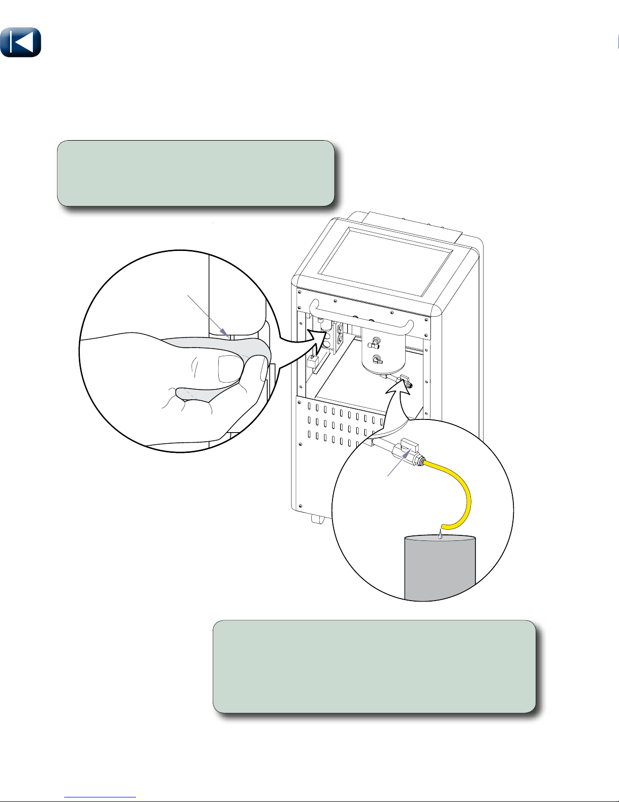
To Drain Condensation from Air Tank...
A) Turn power switch off.
B) Position end of red tube so it drains into a container.
C) Turn drain valve slowly to open.
D) When no water is coming out, slowly close valve.
To Drain Air Regulator...
Place a cloth under the regulator and depress
the button until there is no water coming out.
Valve
Opened
Maintenance continued...
Button
Page 21
© Midmark Corporation 2016
English - 21
TP202 20-42-FO-00014 Rev A1 C2169
003-1879-99
VA1241
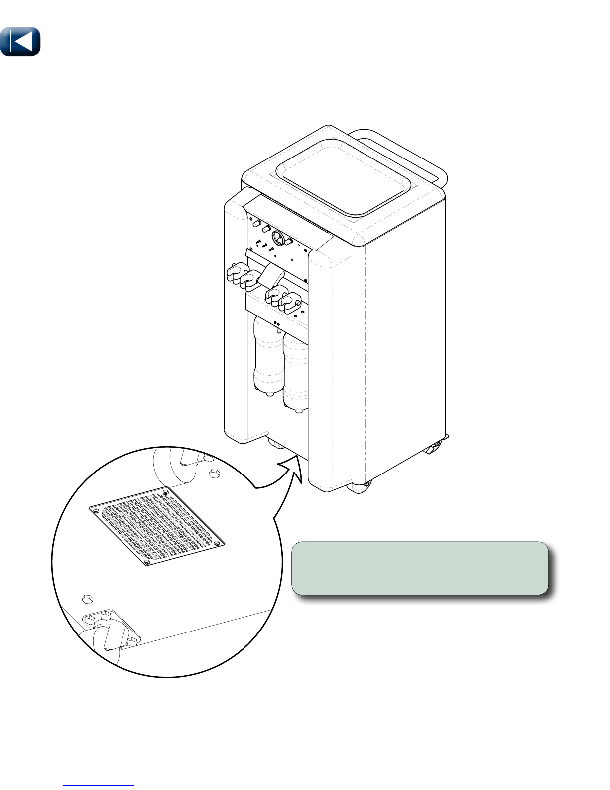
Maintenance continued...
Each Month...
• Clean screen underneath cart with a rag.
Page 22
© Midmark Corporation 2016
English - 22
TP202 20-42-FO-00014 Rev A1 C2169
003-1879-99
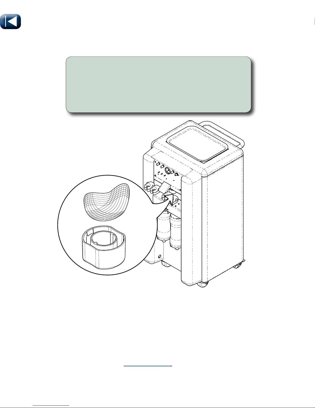
Maintenance continued...
VA1676i
To clean the air/oil separator...
A) Turn master switch OFF.
B) Remove container by squeezing sides in while pulling out.
C) Remove fluid and saturated gauze.
D) Clean container and mounting cap.
E) Install clean gauze and reinstall the container.
Calling For Service
Direct all service inquiries to your authorized Midmark dealer. When
calling for service, you must provide the following information:
Model / serial number
Date of purchase
Symptom(s) of malfunction
Service and Parts Manual is available at www.midmark.com.
Page 23
© Midmark Corporation 2016
English - 23
TP202 20-42-FO-00014 Rev A1 C2169
003-1879-99
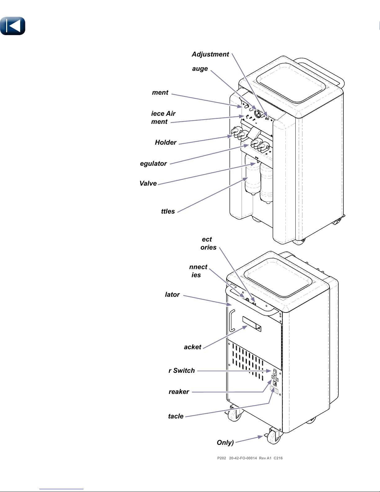
VA1247
Scaler Adjustment
Water Adjustment
Handpiece Pressure Gauge
Handpiece Air
Adjustment
Handpiece Holder
Water Regulator
Water Toggle Valve
Quick Disconnect
Water Accessories
Air Pressure Regulator
Inside Back Door
Quick Disconnect
Air Accessories
On/Off Power Switch
Circuit Breaker
Power Cord Receptacle
Water Bottles
Foot Control Storage Bracket
Locking Casters (Rear Only)
VetPro® 1000
Page 24

© Midmark Corporation 2016
English - 24
TP202 20-42-FO-00014 Rev A1 C2169
003-1879-99
Specifications
Cart
Width 23 inches (58.42 cm)
Length 18 1/2 inches (46.99 cm)
Height 36 1/2 inches (92.71 cm)
Weight 130 lbs (58.97 kg)
Shipping Weight 150 lbs (68.04 kg)
Top of Cart Weight Restriction 25 lbs (11.33 kg)
Compressor
Motor Oil Free 1/3 HP
Working Pressure 70-100 PSI
Flow Rate 2.5 scfm @ 40 PSI
Sound Level (full load) 40 dB
Air Tank 1 Gallon
Water Module
Reservoirs Two - 1 Liter - Toggled
Pressurized System 30-40 PSI
Aseptic Non-Retracting HPC Coolant
Handpiece Flush System Manual
Air and Water Connections External Quick Connects
Other
Duty Cycle Continuous Operation
Note: Exception, Units with LED Scaler,
10 min. ON, 5 min. OFF
Classifications Class 1, Type B Applied Part, except as
noted for optional accessories,
Ordinary Equipment [IPXO]
Optional Accessories:
Acteon Satelec Scaler Type BF Applied Part
High Speed Handpiece with and
without out Fiber Optics
Type B Applied Part
Low Speed Handpiece Type B Applied Part
Air Water Syringe Type B Applied Part
Page 25
© Midmark Corporation 2016
English - 25
TP202 20-42-FO-00014 Rev A1 C2169
003-1879-99
WARNING
Do not modify this equipment without authorization
of the manufacturer.
WARNING
Equipmentnotsuitableforuseinthepresenceofaammableanestheticmixture.
WARNING
To avoid the risk of electric shock, this equipment must ONLY
be connected to supply mains with protective earth.
Electrical(SeeRegulatoryComplianceChart-NextPage)
Fuse (Scaler Transformer) T0.8AL, 250V, 3AG
Circuit Breakers (2) 115VAC 6A 250V, Push to Reset
Circuit Breakers (2) 250VAC 3A 250V, Push to Reset
Power Cord (115VAC) 15A/125VAC x 10 ft. Hospital Grade
Power Cord (230VAC) 10A/250VAC x 2.5 meters
Handpiece
Connection Type Midwest 4-Hole Type Handpiece
Specifications continued...
WARNING
The Acteon Newtron® LED scaler complies with current
electromagnetic compatibility standards. However, it must not
be used by or on those with cardiac stimulators or other active implants
unless adequate electromagnetic interference shielding is present.
Check with a cardiologist to verify the EMI shielding capabilities of the
implant. See enclosed Newtron® LED manual for further advisories.
Page 26

© Midmark Corporation 2016
English - 26
TP202 20-42-FO-00014 Rev A1 C2169
003-1879-99
ModelIdentication/ComplianceChart
Model Description
Complies To: Electrical Ratings:
UL
60601-1,
Ed. 1
CAN / CSA
22.2,
#601.1-M90
IEC
60601-1,
Ed. 2
CE
VAC
+/- 10%
Amps
Cycles
(Hz)
8000-001 VetPro 1000 w/ Scaler
• • • •
115 6 60
8000-002 VetPro 1000 w/o Scaler
• • • •
115 6 60
8000-003 VetPro 1000 w/ Scaler and
Fiber Optics
• • • •
115 6 60
8000-004 VetPro 1000 w/o Scaler
and Fiber Optics
• • • •
115 6 60
8000-005 VetPro 1000 w/ Scaler,
Export
•
230 3 50
8000-006 VetPro 1000 w/ LED Scaler
and Fiber Optics. Export
•
230 3 50
8000-006S VetPro 1000 w/ LED Scaler
and Swivel Fiber Optics.
Export
•
230 3 50
8000-007 VetPro 1000 w/ LED Scaler
and 2 Position Fiber Optics
• • • •
115 6 60
8000-007S VetPro 1000 w/ LED Scaler
and 2 Position Swivel Fiber
Optics
• • • •
115 6 60
8000-008 VetPro 1000 w/ Scaler and
Fiber Optics
• • • •
115 6 60
8000-008S VetPro 1000 w/ Scaler and
Swivel Fiber Optics
• • • •
115 6 60
Page 27

© Midmark Corporation 2016
English - 27
TP202 20-42-FO-00014 Rev A1 C2169
003-1879-99
SCOPE OF WARRANTY Midmark Corporation (“Midmark”) warrants to the original retail purchaser that it will repair or replace components of the animal health products manufactured by Midmark (except for products and components not warranted under “Exclusions”)
that are defective in material or workmanship under normal use and service. The sole remedy under this limited warranty is the repair
or replacement, at Midmark’s option, of the applicable products or components. This limited warranty shall only apply to defects that:
(i) are reported to Midmark within the applicable warranty period; and (ii) are determined to exist upon examination by Midmark. This
limited warranty extends only to the original retail purchaser of a product, and is not transferable or assignable.
APPLICABLE WARRANTY PERIOD The applicable warranty period, measured from the date of delivery to the original user, shall be
as follows: The VetPro® 1000 unit is warranted against defect in material and workmanship for a period of two years from the
time of delivery.
PRODUCTS are warranted against defect in material and workmanship for the period indicated below from the time of delivery:
a) 2 years for all products and components (except for the periods in b and c).
b) Accessories not manufactured by Midmark are excluded (i.e. Fiber optic systems, Scalers, Handpieces, etc.).
c) Replacement parts and accessories carry a 90 day warranty
OBTAINING WARRANTY SERVICE Warranty service must be obtained through either Midmark or an authorized dealer in the Midmark
product line for which warranty service is requested. Midmark may be contacted for warranty service inquiries or issues via email at
www.midmark.com, by mail to Midmark Corporation, 60 Vista Drive, Versailles, Ohio 45380, or by phone at: 1-800-MIDMARK.
It is the retail purchaser’s obligation to arrange for delivery of a product to Midmark or one of its authorized dealers for warranty service, which delivery shall be at retail purchaser’s expense. It is also the retail purchaser’s obligation to comply with the warranty service
instructions provided either by Midmark or its authorized dealer. The retail purchaser must provide Midmark with completed warranty
registration information within thirty (30) days after purchase in order to obtain the benefits of this limited warranty.
EXCLUSIONS This limited warranty does not cover and Midmark shall not be liable for the following:
(1) defects, damage or other conditions caused, in whole or in part, by misuse, abuse, negligence, alteration, accident (including animal acts of any kind), freight damage, tampering or failure to seek and obtain repair or replacement in a timely manner;
(2) matching of color, grain or texture except to commercially acceptable standards;
(3) changes in color caused by natural or artificial light;
(4) products which are not installed, used and properly cleaned and maintained as required in the installation and operation manuals
for the applicable product (imaging product must be installed by a certified Midmark installer);
(5) products considered to be of a consumable nature;
(6) accessories or parts not manufactured by Midmark;
(7) specially manufactured products;
(8) charges by anyone (including Midmark’s authorized dealers) for adjustments, repairs, replacement parts, installation or other work
performed upon or in connection with such products which are not expressly authorized in writing in advance by Midmark;
(9) costs and expenses of routine maintenance and cleaning;
(10) all sinks, faucets and plumbing accessories;
(11) representations and warranties made by any person or entity other than Midmark; and
(12) with respect to software that is a product or a component thereof, that the software will be error free, can be used without problems or interruptions, or will be free from vulnerability to intrusion or attack by viruses or other methods.
EXCLUSIVE REMEDY; CONSEQUENTIAL DAMAGES DISCLAIMER Midmark’s only obligation under this limited warranty is the
repair or replacement of defective parts. Midmark shall not be liable for and hereby disclaims any direct, special, indirect, incidental, exemplary or consequential damages or delays including, but not limited to, damages for loss of profits or income, loss of use, downtime,
cover, and employee or independent contractor wages, payments and benefits. This disclaimer shall survive any failure or asserted
failure of the essential purpose of this limited warranty or its remedies specified herein.
NO AUTHORIZATION No person or firm is authorized to create or approve for Midmark any other obligation or liability in connection
with Midmark products.
WARRANTY DISCLAIMER: THIS LIMITED WARRANTY IS MIDMARK’S ONLY WARRANTY AND IS IN LIEU OF ALL OTHER WARRANTIES, EXPRESS OR IMPLIED. MIDMARK MAKES NO IMPLIED WARRANTIES OF ANY KIND INCLUDING ANY IMPLIED WARRANTIES OF MERCHANTABILITY OR FITNESS FOR A PARTICULAR PURPOSE.
STATUTE OF LIMITATIONS No action may be brought against Midmark for breach of this limited warranty, an implied warranty, if any,
or for any other claim arising out of or relating to the products, more than ninety (90) days following expiration of the warranty period.
In the event multiple warranty periods exist with respect to a product, the ninety (90) day period provided for herein shall begin to run
from expiration of the warranty period for the component to which the claim relates.
SEVERABILITY In the event any provision of this limited warranty is determined to be invalid or otherwise unenforceable: (i) the provision shall be enforced in a manner that closest holds to its intent, while at the same time curing the invalidity or unenforceability, and
(ii) the balance of this limited warranty, being severable, shall not be affected in the event the provision that is invalid or unenforceable
cannot be enforced in any respect.
Warranty
Page 28

Midmark Corporation
60 Vista Drive
Versailles, OH 45380 USA
1-800-643-6275
1-937-526-3662
003-1879-99
TP202 20-42-FO-00014 Rev A1 C2169
Page 29

TP202 20-42-FO-00014 Rev A1 C2169
Guía del usuario
VetPro® 1000
Sistema Dental Móvil
Para modelos:
8000-001
8000-002
8000-003
8000-004
8000-005
8000-006
8000-006S
8000-007
8000-007S
8000-008
8000-008S
English
Español
Français
Page 30

© Midmark Corporation 2016
Español - 2
TP202 20-42-FO-00014 Rev A1 C2169
003-1879-99
Información del producto
(La siguiente información es necesaria al llamar para solicitar mantenimiento.)
Modelo / Número de serie:
Fecha de compra:
Empresa de mantenimiento
autorizada por Midmark:
Distribuidor:
Ubicación del modelo / número de serie
Page 31

© Midmark Corporation 2016
Español - 3
TP202 20-42-FO-00014 Rev A1 C2169
003-1879-99
Índice
Información importante
Símbolos de seguridad ........................................................................................................4
Uso indicado ........................................................................................................................ 5
Interferencias electromagnéticas.........................................................................................5
Eliminación de equipos........................................................................................................5
Representante autorizado en la CE ....................................................................................5
Condiciones de transporte, almacenamiento y funcionamiento .......................................... 5
Transporte
Transporte del sistema dental .............................................................................................6
Funcionamiento
Sistema eléctrico .................................................................................................................7
Sistema del agua .................................................................................................................8
Sistema del aire ................................................................................................................... 9
Sistema dental ..................................................................................................................... 10
Cuidado de las piezas de mano .......................................................................................... 11
Instalación y sustitución de las piezas de mano y la punta de jeringa ................................ 12
Ajuste del aire de accionamiento y las ruedas de bloqueo .................................................13
Ajuste del flujo de agua y del regulador de presión de aire ................................................14
Ajuste del aire frío................................................................................................................15
Limpieza y mantenimiento
Limpieza ..............................................................................................................................16
Mantenimiento ..................................................................................................................... 18
Servicio técnico ...................................................................................................................22
Especificaciones
Plano ...................................................................................................................................23
Peso / Dimensiones.............................................................................................................24
Especificaciones eléctricas..................................................................................................25
Identificación del modelo / Tablas de cumplimiento de las normativas ............................... 26
Garantía
Información de garantía.......................................................................................................27
Para información sobre instalación, visite:
“Technical Library” en Midmark.com
Page 32

© Midmark Corporation 2016
Español - 4
TP202 20-42-FO-00014 Rev A1 C2169
003-1879-99
Tipo B, pieza aplicada
Límite de temperatura
Manejar con cuidado
Límite de humedad
Clasificación
del fusible
Especificaciones
Límite de presión
Símbolos de seguridad
Información importante
Método de transporte
correcto Orientación
Altura máxima de apilado
(No apilar)
Frágil
Manténgase seco
Consulte el folleto o
manual de instrucciones
ADVERTENCIA
Indica una situación potencialmente peligrosa que podría ocasionar lesiones graves.
Precaución
Indica una situación potencialmente peligrosa que puede ocasionar lesiones leves o
moderadas. También puede usarse para alertar contra prácticas peligrosas.
Alerta del equipo
Indica una situación potencial-
mente peligrosa que, de no evitarse,
podría provocar daños al equipo.
Nota
Amplía la información sobre un procedimiento,
un método o un error de funcionamiento.
Tipo BF, pieza aplicada
Toma de tierra de
protección
Pieza de mano del
escarificador LED
Ciclo de utilización
US
C
TUVRheinland
TUV - Sólo
modelos domésticos
No volcar
100 F
38 C
23 F
-5 C
Page 33

© Midmark Corporation 2016
Español - 5
TP202 20-42-FO-00014 Rev A1 C2169
003-1879-99
Cómo deshacerse del equipo
Al final del ciclo de vida del producto, tanto la(s) unidad(es) como sus accesorios y otros productos fungibles podrían estar
contaminados por efecto de su uso habitual. Consulte las ordenanzas y códigos locales para ver la forma
adecuada de desechar
estos equipos y otros productos fungibles.
Representante autorizado para la EU
Los países pertenecientes a la EU deben dirigir todas las preguntas, incidentes y reclamaciones al representante autorizado de Midmark en la EU que se indica a continuación:
Midmark EMEA Ltd
Beech House
First Floor, East Wing
Ancells Business Park
Fleet
Hampshire GU51 2UN
United Kingdom
Tel: + 44 (0) 1252 360 940
Fax: + 44 (0) 1252 360 941
Condiciones de transporte, almacenamiento y funcionamiento
Rango de temperaturas de transporte y almacenamiento: ........... -5ºC a 38ºC (23°F a 100°F)
Rango de temperatura de funcionamiento: ................................... 10ºC a 40ºC (50ºF a 104ºF)
Humedad relativa durante transporte/almacenamiento:................ 10% a 90% (sin condensación)
Humedad relativa durante el funcionamiento: ............................... 30% a 75% (sin condensación)
Presión atmosférica durante transporte/almacenamiento: ............ 50 kPA (7.2 PSI) a 106 kPA (15.3 PSI)
Presión atmosférica durante el funcionamiento: ........................... 700 hPA (20 in Hg) a 1060 hPA (31 in Hg)
Uso indicado
El sistema Midmark® VetPro® 1000 es un sistema dental móvil diseñado para proporcionar a veterinarios
o técnicos cualificados una unidad autónoma, compacta y portátil para realizar procedimientos dentales
veterinarios.
Interferencias electromagnéticas
Este producto se ha diseñado y construido para reducir al mínimo las interferencias electromagnéticas
con otros dispositivos.
Sin embargo, si detecta interferencias entre otros dispositivo y este carro:
•Saqueeldispositivoquecauseinterferenciasfueradelasala
•Enchufeelcarroauncircuitoaislado
•AumentelaseparaciónentreelproductodeMidmarkyeldispositivoquecauselasinterferencias
•PóngaseencontactoconMidmarksipersistenlasinterferencias
Page 34

© Midmark Corporation 2016
Español - 6
TP202 20-42-FO-00014 Rev A1 C2169
003-1879-99
Transporte
ADVERTENCIA
Al trasladar el dispositivo, tenga cuidado al pasar por los umbrales de las
puertas y cerca de objetos a ras de suelo.
De lo contrario se pueden producir lesiones.
Umbral
Al transportar a través de escalones o umbrales
muy altos...
A) Empuje el carro hacia arriba y sobre una superficie nivelada.
Page 35

© Midmark Corporation 2016
Español - 7
TP202 20-42-FO-00014 Rev A1 C2169
003-1879-99
6
A
M
P
6
A
M
P
VA1227
Funcionamiento
Sistema eléctrico
Interruptor de encendido/apagado
El interruptor de encendido/apagado está situado en la parte posterior del carro. Controla la fuente principal
de alimentación y siempre debe estar en posición ENCENDIDO (ON) para que el sistema dental funcione.
Cortacircuitos
Hay dos cortacircuitos situados en el panel posterior inferior del carro. Si se supera la carga máxima de la
unidad, los cortacircuitos interrumpirán la alimentación. La carga máxima es de 115 V CA, 6 A (doméstico)
o 230 V CA, 3 A (exportación).
Desconexión de la red eléctrica
Puede interrumpirse la alimentación desenchufando el cable o apagando el interruptor.
(O) Interruptor
apagado
( I ) Interruptor
encendido
Cortacircuitos
Desactivado
(Sin energía)
Desconexión
de la red
eléctrica
Reestablecer
(alimentación)
Page 36

© Midmark Corporation 2016
Español - 8
TP202 20-42-FO-00014 Rev A1 C2169
003-1879-99
VA1229
Funcionamiento
Sistema de agua
Botellas de agua
La unidad tiene dos botellas de un litro. Las botellas de agua suministran agua a las piezas de mano,
a la jeringa de aire/agua y a una toma de desconexión rápida en la parte posterior del carro. El aire
fluye a través del regulador del agua y del conmutador hasta alcanzar las botellas de agua. El sistema
de agua está regulado a 40 PSI. Utilice la válvula de aguja del agua para ajustar el flujo de agua para
cada instrumento. El conmutador situado entre las botellas de agua controla qué botella suministra el
agua. Cuando el conmutador está en el centro ninguna de las botellas está presurizada. Desplace el
conmutador hacia la izquierda para presurizar la botella izquierda y despresurizar la botella derecha.
Desplácelo hacia la derecha para presurizar la botella derecha y despresurizar la izquierda.
Conmutador
Para llenar las botellas de agua...
A) Desplace el conmutador al centro.
B) Retire la botella de agua y llénela (se recomienda usar agua destilada).
C) Vuelva a colocar la botella de agua y desplace el conmutador hacia la botella de agua llena.
Nota: Las botellas de agua deben comprobarse entre un paciente y otro y llenarse si es necesario.
Toma de desconexión rápida de agua
La toma de desconexión rápida de agua tiene un anillo azul. Puede acoplar accesorios al carro que
usarán el agua del mismo. Es posible que tenga que añadir un regulador si el equipo conectado no
admite 40 PSI.
Válvula de
aguja del água
Regulador
del agua
Botellas de
agua
Toma de
desconexión
rápida
de agua
Precaución
Si no se cierran herméticamente las botellas de agua el
paciente puede sufrir lesiones.
Page 37

© Midmark Corporation 2016
Español - 9
TP202 20-42-FO-00014 Rev A1 C2169
003-1879-99
VA1231
Funcionamiento
Sistema de aire
Compresor
El sistema neumático consta de un compresor de 1/3 HP con un depósito de aire de dos litros y un regulador. Suministra aire a las
piezas de mano, a la jeringa de aire/agua y a una toma de desconexión rápida en la parte posterior del
carro. El compresor funciona entre 70 PSI y 100 PSI. El regulador se ajusta en fábrica a 65 PSI.
Toma de desconexión rápida de aire
La toma de desconexión rápida de aire tiene un anillo rojo. Puede acoplar accesorios al carro que
usarán el aire del mismo. Es posible que tenga que añadir un regulador si el equipo conectado no admite
100 PSI.
Tornillo de ajuste del
aire de refrigeración
Mando de ajuste del aire
de accionamiento
Toma de desconexión rápida de aire
Respiradero
Compartimento del compresor
Soporte del pedal de control
Alerta del equipo
No obstruya el respiradero.
Page 38

© Midmark Corporation 2016
Español - 10
TP202 20-42-FO-00014 Rev A1 C2169
003-1879-99
VA1233
Piezas de mano
El sistema dental controla hasta cuatro piezas de mano. La presión de las piezas de mano se controla
mediante las válvulas de ajuste del aire de accionamiento. El medidor de la parte delantera del sistema
dental indica la presión de la pieza de mano. La presión de la pieza de mano no debe superar los 60 PSI
durante el funcionamiento normal. El escarificador (opcional) tiene un mando de ajuste para regular el
nivel de intensidad.
Funcionamiento
Sistema dental
Jeringa de aire/agua
Hay botones de aire y agua en la parte superior de la jeringa. Cuando se pulsan ambos botones se obtiene
una nebulización de aire y agua Los ajustes de aire y agua están situados debajo del soporte de la jeringa.
Inserte un destornillador plano en los tornillos de ajuste. Gire en el sentido de las agujas del reloj para
reducir el flujo y en el sentido contrario para aumentarlo. Gire el tornillo hasta que el flujo de aire/agua
deseado salga a través del instrumento.
Medidor
Aire
Agua
Alerta del equipo
Consulte con el fabricante de
la pieza de mano los ajustes de PSI
recomendados. Compruebe únicamente
una pieza de mano cada vez.
Pieza de
mano las
piezas de
mano
Ajuste del
Mando de
Aire
Agua
Precaución
La punta de la jeringa y de las piezas de mano
han de cambiarse o desinfectarse entre un paciente y otro.
Taladro
Pulidora
Jeringa
Escalador
Page 39

© Midmark Corporation 2016
Español - 11
TP202 20-42-FO-00014 Rev A1 C2169
003-1879-99
Funcionamiento
Para cambiar la fresa de la pieza de mano de alta velocidad...
A) Pulse el botón de la parte posterior de la pieza de mano y tire de la fresa
hasta extraerla.
B) Introduzca la fresa en la pieza de mano. (El vástago sólo entrará hasta la
mitad).
C) A continuación pulse el botón de la parte posterior de la pieza de mano y
empuje la fresa hasta que el vástago entre por completo.
Nota: Las fresas de agarre de fricción (estilo FG) se han diseñado para que toda la parte recta del
vástago esté en el interior del portafresas de la pieza de mano. Si la fresa está instalada correctamente,
sólo se debe ver la parte cónica de la fresa. Se recomienda usar una fresa nueva para cada paciente.
Ángulo pro-
láctico
Sustitución del ángulo profiláctico
Para cambiar el ángulo profiláctico...
A) Gire el portafresas a la derecha para desbloquearlo.
Instale el ángulo profiláctico y gire el anillo de liberación
del portafresas a la izquierda para apretarlo.
Presione
Botón
Introduzca la fresa en la
pieza de mano
Termine de introducir la
fresa en la pieza de mano
Vástago dentro de la pieza
de mano
Esta parte de la
fresa debe estar
dentro de la pieza
de mano
Sustitución de la fresa
Page 40

© Midmark Corporation 2016
Español - 12
TP202 20-42-FO-00014 Rev A1 C2169
003-1879-99
Instalación de pieza de mano
Instale las piezas de mano.
VA1807i
Para cambiar la punta de la jeringa...
A) Presione hacia abajo el collarín grande.
B) Cuando sienta un “clic” suave, tire de la punta en
línea recta.
C) Mantenga presionado el collarín e introduzca la
nueva punta. Asegúrese de introducirlo hasta el
fondo completamente y luego suelte el collarín.
D) Compruebe la instalación tirando firmemente de la
punta para ver si se ha insertado hasta el fondo y
está bloqueada en su sitio.
Sustitución de la punta de la jeringa
Alinear correctamente los
componentes para prevenir que
la pieza de mano se dañe y en
consecuencia se estropee.
Pulverice ligeramente las juntas tóricas
expuestas con un lubrificante en un paso.
Apriete el acoplador con firmeza
con una llave inglesa.
Conexión de acoplador
giratorio
Nota
No todas las unidades estarán equipadas con un módulo de lámpara.
Soporte
de las
piezas de
mano
Page 41

© Midmark Corporation 2016
Español - 13
TP202 20-42-FO-00014 Rev A1 C2169
003-1879-99
Ajuste del aire de accionamiento y ruedas de bloqueo
Mando de ajuste del
aire de accionamiento
Para ajustar el aire de accionamiento...
Inserte un destornillador de cabeza plana en el mando
de ajuste del aire de accionamiento (de la pieza de mano
deseada). Gire el mando hasta que se muestre la presión
de aire adecuada en el medidor de presión.
OFF para
desbloquear
ON para bloquear
Page 42

© Midmark Corporation 2016
Español - 14
TP202 20-42-FO-00014 Rev A1 C2169
003-1879-99
Funcionamiento
Disminuir
Aumentar
Mando de
ajuste
Desbloquear
Bloquear
Ajuste del regulador de presión
del aire
ALERTA DEL EQUIPO
No ajuste el regulador por
encima de 65 PSI.
Para ajustar el regulador...
A) Tire hacia arriba del mando de ajuste
para desbloquearlo.
B) Gire el mando de ajuste en el sentido
de las agujas del reloj para aumentar
la presión y en el sentido contrario para
reducirla.
C) Empuje el mando de ajuste hacia abajo
para bloquearlo.
Para ajustar el flujo de agua...
Gire la válvula de aguja del agua (de la pieza de mano que desee) hasta
conseguir el flujo deseado.
Válvula de aguja del agua
Ajuste del flujo de agua
Page 43

© Midmark Corporation 2016
Español - 15
TP202 20-42-FO-00014 Rev A1 C2169
003-1879-99
Funcionamiento
Para ajustar el aire frío...
Inserte un destornillador de cabeza plana en el mando de ajuste
del aire frío (de la pieza de mano deseada). Gire en el sentido de
las agujas del reloj para reducir el flujo y en el sentido contrario
para aumentarlo. Gire el tornillo hasta que salga la presión de aire
deseada a través del instrumento.
Nota: Los tornillos de ajuste de aire de accionamiento están situados debajo de los
soportes de herramientas de cada instrumento.
Tornillos de ajuste del
aire de refrigeración
Ajuste de aire frío
Page 44

© Midmark Corporation 2016
Español - 16
TP202 20-42-FO-00014 Rev A1 C2169
003-1879-99
Nota:
Utilice solo una solución de lejía al 5,25%. No utilice
lejía aromatizada, con protector del color u otros aditivos.
Cambie la mezcla todos los días.
~90%
~10%
Limpieza
•Utilicelimpiadoresadecuadosparalasituación,comoaguatempladaydetergentessuaves
o una solución de agua y lejía al 10%.
•Limpielassuperficiesexterioresconunpañolimpiosinpelusahumedecidocon
desinfectante. No vierta ningún líquido en respiraderos abiertos, enchufes ni conectores.
Seque las superficies con un paño limpio o una toalla de papel.
•Despuésdelalimpieza,inspeccionevisualmenteelproductoenbuscadedeteriorode
cubiertas. No use el sistema dental si nota decoloración excesiva, grietas u otros signos de
desgaste (consulte las instrucciones dadas para Contactar con el servicio técnico).
Page 45

© Midmark Corporation 2016
Español - 17
TP202 20-42-FO-00014 Rev A1 C2169
003-1879-99
Nota
Cadaconsultorioveterinarioesdiferenteynohayningúndesinfectanteespecícoquesealamejor
opción para todas las instalaciones. Existen varias organizaciones que ofrecen información sobre
procedimientosdedesinfección.Consultelossitioswebdefuentesconablesquepuedenayudaral
personal veterinario a elegir lo mejor para sus consultorios. A continuación se indican algunos de estos
sitios.
Organización de Seguridad y Procedimientos de Asepsia
http://www.osap.org
Departamento de salud y recursos humanos de Centros para el Control y la Prevención de
Enfermedades (CDC)
http://www.cdc.gov
Cuando utilice desinfectantes...
• Lea cuidadosamente la etiqueta del
producto y las instrucciones de uso.
• No supere la tasa de disolución.
DA148100i
Read
carefully
Alerta del equipo
Consulte con el fabricante de las
piezas de mano para ver los procedimientos
de limpieza recomendados.
Limpieza continuación...
Lea
atentamente
Page 46

© Midmark Corporation 2016
Español - 18
TP202 20-42-FO-00014 Rev A1 C2169
003-1879-99
Mantenimiento
Al principio de cada jornada de trabajo...
• Llene las botellas de agua con agua
destilada limpia.
• Lave las piezas de mano.
Entre un paciente y otro...
• Retire las puntas, instrumentos, etc.,
desechables.
• Lave el sistema dental.
• Desinfecte las piezas de mano y el
escarificador según las instrucciones
del fabricante.
• Desinfecte la punta de la jeringa.
• Llene las botellas de agua.
Para lavar el sistema dental...
A) Extraiga todas las piezas de mano que utilizan agua.
B) Abra la válvula de aguja del agua.
C) Sostenga el extremo del tubo sobre un recipiente y pise el pedal de control.
D) Deje que corra el agua entre 20 y 30 segundos.
E) Instale las piezas de mano y la punta de la jeringa recién desinfectadas.
F) Rellene la botella de agua.
Válvula de aguja del agua
Nota
No es obligatorio el uso de agua
destilada. Sin embargo, el agua debe
ser potable.
Alerta del equipo
ESTERILIZACIÓN DE LA PUNTA DE LA JERINGA DESINFECTABLE AL AUTOCLAVE
Las puntas de jeringa desinfectables al autoclave que se adjuntan con el sistema dental
deben esterilizarse antes de su uso con cada paciente, incluido su primer uso. Asegúrese de
enjuagar y limpiar cuidadosamente las puntas de jeringa antes de esterilizarlas, ya que cualquier
suciedad puede reducir la eficacia de la esterilización. El proceso de esterilización recomendado
es el de autoclave de vapor. Los parámetros de temperatura y presión recomendados son 125°C
(250°F) y 106 kPa (15 PSI) durante 40 minutos.
Alerta del equipo
ESTERILIZACIÓN DE LAS PIEZAS
DE MANO
Entre cada procedimiento, lleve
a cabo las instrucciones del fabricante para
Control de infección/Esterilización que hallará
en la documentación incluida con las piezas de
mano. Si no lo hace así se puede producir un fallo
prematuro de las piezas de mano.
Page 47

© Midmark Corporation 2016
Español - 19
TP202 20-42-FO-00014 Rev A1 C2169
003-1879-99
BLEACH
Mantenimiento continuación...
Al final de cada día...
• Lave con solución de lejía el
sistema dental y vacíe el sistema
de agua.
• Drene el regulador de aire.
• Elimine la condensación del
recipiente de aire.
• Limpie el sistema.
ALERTA DEL EQUIPO
No utilice lejía de color/perfumada ni concentraciones mayores de
las recomendadas. No mantenga la solución de lejía en el sistema dental
durante más de 30 minutos, ya que esto podría dañar el sistema.
Para lavar con solución de lejía el sistema dental...
A) Extraiga todas las piezas de mano que utilizan agua.
B) Retire las botellas de agua y llénelas con 9 partes de agua y 1 de lejía.
C) Abra la válvula de aguja del agua.
D) Sostenga el extremo del tubo sobre un recipiente y pise el pedal de control.
E) Deje que corra el agua durante 20 o 30 segundos.
F) Deje que la solución de lejía permanezca en el sistema dental durante 10-20 minutos,
y luego retire, vacíe y enjuague las botellas de agua.
G) Llene las botellas de agua con agua limpia y repita los pasos C a E hasta que
desaparezca el olor a lejía.
H) Instale las piezas de mano y la punta de la jeringa recién desinfectadas.
I) Vacíe las botellas de agua.
Lejía
Page 48

© Midmark Corporation 2016
Español - 20
TP202 20-42-FO-00014 Rev A1 C2169
003-1879-99
VA1238
Para eliminar la condensación del depósito de aire...
A) Apague el interruptor de alimentación.
B) Coloque el extremo del tubo rojo de modo que se vacíe
en un contenedor.
C) Gire la válvula de drenaje lentamente para abrirla.
D) Cuando no salga agua, cierre la válvula lentamente.
Para drenar el regulador de aire...
Coloque un paño bajo el regulador y oprima
el botón hasta que deje de salir agua.
Válvula
abierta
Mantenimiento continuación...
Botón
Page 49

© Midmark Corporation 2016
Español - 21
TP202 20-42-FO-00014 Rev A1 C2169
003-1879-99
VA1241
Mantenimiento continuación...
Cada mes...
• Limpie con un trapo la rejilla que está en
la parte inferior del carro.
Page 50

© Midmark Corporation 2016
Español - 22
TP202 20-42-FO-00014 Rev A1 C2169
003-1879-99
Mantenimiento continuación...
VA1676i
Para limpiar el separador de aire y aceite...
A) APAGUE el interruptor general.
B) Saque el recipiente apretando los lados hacia adentro al mismo
tiempo que tira hacia afuera.
C) Retire el fluido y la gasa saturada.
D) Limpie el recipiente y la tapa de montaje.
E) Instale una gasa limpia y vuelva a colocar el recipiente.
Servicio técnico
Todas las solicitudes de servicio técnico se deben dirigir a un distribuidor autorizado de Midmark. Al solicitar
servicio técnico, debe proporcionar la información siguiente:
Modelo / número de serie
Fecha de compra
Síntomas del fallo
Puede consultar el Manual de Servicio y Piezas en www.midmark.com.
Page 51

© Midmark Corporation 2016
Español - 23
TP202 20-42-FO-00014 Rev A1 C2169
003-1879-99
VA1247
Ajuste del escaricador
Ajuste del agua
Manómetro de las piezas de mano
Ajuste del aire de
las piezas de mano
Soporte de las piezas de mano
Regulador del agua
Válvula de conmutación de agua
Toma de desconexión rápida
para accesorios de agua
Regulador de presión de aire
dentro de la puerta trasera
Toma de desconexión rápida
para accesorios neumáticos
Interruptor de encendido/apagado
Cortacircuitos
Toma de corriente del cable de alimentación
Botellas de agua
Soporte de almacenamiento del pedal de control
Ruedas de bloqueo (sólo traseras)
VetPro® 1000
Page 52

© Midmark Corporation 2016
Español - 24
TP202 20-42-FO-00014 Rev A1 C2169
003-1879-99
Especificaciones
Carro
Anchura 58,42 cm (23 inches)
Longitud 46,99 cm (18 1/2 inches)
Altura 92,71 cm (36 1/2 inches)
Peso 58,97 Kg. (130 lbs.)
Peso de transporte 68,04 Kg. (150 lbs.)
Restricción de peso de la parte
superior del carro
11,33 Kg. (25 lbs.)
Compresor
Motor 1/3 HP, no necesita aceite
Presión de trabajo 70-100 PSI
Caudal 2,5 scfm a 40 PSI
Nivel acústico (a plena carga) 40 dB
Depósito de aire 3,8 l (1 gallon)
Módulo de agua
Depósitos Dos - 1 litro - conmutados
Sistema presurizado 30-40 PSI
Asepsia Refrigerante HPC sin retracción
Sistema de lavado de las piezas de
mano
Manual
Conexiones del aire y del agua Tomas de conexión rápida externas
Otros
Ciclo de utilización Funcionamiento continuo
Nota: excepción, unidades con escarificador LED, 10 min. encendido, 5 min.
apagado
Clasificaciones Clase I, parte aplicada Tipo B, excepto
según se indica para accesorios opcionales, equipo ordinario [IPX0]
Accesorios opcionales:
Escarificador Acteon Satelec Tipo BF, pieza aplicada
Pieza de mano de alta velocidad
con y sin fibra óptica
Tipo B, pieza aplicada
Pieza de mano de baja velocidad Tipo B, pieza aplicada
Jeringa de aire/agua Tipo B, pieza aplicada
Page 53

© Midmark Corporation 2016
Español - 25
TP202 20-42-FO-00014 Rev A1 C2169
003-1879-99
ADVERTENCIA
No modifique este equipo sin autorización del fabricante.
ADVERTENCIA
El equipo no se puede utilizar en presencia de mezclas anestésicas inamables.
ADVERTENCIA
Para evitar riesgo de descarga eléctrica, este equipo debe conectarse
ÚNICAMENTE a enchufes provistos de toma a tierra.
Especificaciones eléctricas (consulte la tabla de
cumplimiento de las normativas en la página siguiente)
Fusible (transformador del escarificador)
T0.8AL, 250 V, 3AG
Cortacircuitos (2) 115 V CA 6 A 250 V, Presionar para restablecer
Cortacircuitos (2) 250 V CA 3A 250 V, Presionar para restablecer
Cable de alimentación (115 V CA) 15 A/125 V CA x 3,3 m. (10 pies) cla-
sificación para hospitales
Cable de alimentación (230 V CA) 10 A/250 V CA x 2,5 m.
Pieza de mano
Tipo de conexión Pieza de mano tipo Midwest de cuatro
orificios
Especificaciones continuación...
ADVERTENCIA
El limpiador de sarro con tecnología LED Newtron® de Acteon cumple
las normas de compatibilidad electromagnética actuales. No obstante, las personas
que tengan estimuladores cardíacos u otros implantes activos no deben utilizarlo, ni se debe
utilizar en animales con estimuladores cardíacos u otros implantes activos, a menos que se
cuente con protección contra las interferencias electromagnéticas. Se deberá consultar con
un cardiólogo para conocer las capacidades de protección contra interferencias electromagnéticas del implante. Pueden encontrarse más avisos en el manual de la luz Newtron® LED
adjunto
Page 54

© Midmark Corporation 2016
Español - 26
TP202 20-42-FO-00014 Rev A1 C2169
003-1879-99
Identicación del modelo y tablas de cumplimiento de
las normativas
Modelo Descripción
Conformidad con: Clasificaciones eléctricas:
UL
60601-1,
Ed. 1
CAN / CSA
22.2,
#601.1-M90
IEC
60601-1,
Ed. 2
CE
V CA
+/- 10%
Am-
perios
Ciclos
(Hz)
8000-001 VetPro 1000 con escari-
ficador
• • • •
115 6 60
8000-002 VetPro 1000 sin escari-
ficador
• • • •
115 6 60
8000-003 VetPro 1000 con escari-
ficador y fibra óptica
• • • •
115 6 60
8000-004 VetPro 1000 sin escarifica-
dor ni fibra óptica
• • • •
115 6 60
8000-005 VetPro 1000 con escari-
ficador (para exportación)
•
230 3 50
8000-006 VetPro 1000 con escari-
ficador LED y fibra óptica
Exportación
•
230 3 50
8000-006S VETPro 1000 con escari-
ficador LED y fibra óptica
giratoria. Exportación
•
230 3 50
8000-007 VetPro 1000 con escari-
ficador LED y fibra óptica
de dos posiciones
• • • •
115 6 60
8000-007S VETPro 1000 con escari-
ficador LED y fibra óptica
giratoria de dos posiciones
• • • •
115 6 60
8000-008 VetPro 1000 con escari-
ficador y fibra óptica
• • • •
115 6 60
8000-008S VETPro 1000 con es-
carificador y fibra óptica
giratoria
• • • •
115 6 60
Page 55

© Midmark Corporation 2016
Español - 27
TP202 20-42-FO-00014 Rev A1 C2169
003-1879-99
COBERTURA DE LA GARANTÍA, Midmark Corporation («Midmark») garantiza al comprador minorista original que reparará o reemplazará los
componentes de los productos de salud animal fabricados por Midmark (excepto los productos y componentes no garantizados en «Exclusiones»)
que contengan materiales defectuosos o fallos de mano de obra en condiciones normales de uso y servicio. La responsabilidad única en virtud de
esta garantía limitada es a la reparación o la sustitución, a discreción de Midmark, de los productos o componentes aplicables. La garantía limitada
solo se aplicará a los defectos que: (i) se notifiquen a Midmark dentro del período de garantía aplicable; y (ii) cuya existencia se llega a determinar
tras un examen efectuado por Midmark. Esta garantía limitada se expide únicamente al comprador minorista original de un producto y no es
transferible ni asignable.
PERÍODO DE GARANTÍA APLICABLE l período de validez de la garantía a partir de la fecha de entrega al usuario original será el siguiente:
La unidad VetPro
®
1000 está garantizada frente a defectos de material o fabricación durante un período de dos años a partir del momento de la
entrega.
LOS PRODUCTOS ODONTOLÓGICOS están bajo garantía frente a defectos de material y fabricación durante el período que se indica a
continuación a partir de la fecha de entrega:
a) Dos años para todos los productos y componentes (excepto los periodos que se indican en los apartados b y c).
b) Quedan excluidos los accesorios no fabricados por Midmark (es decir, sistemas de fibra óptica, escarificadores, piezas de mano, etc.).
c) Las piezas de recambio y los accesorios tienen una garantía de 90 días.
OBTENCIÓN DEL SERVICIO DE GARANTÍA El servicio de garantía debe obtenerse a través de un distribuidor de Midmark o un distribuidor
autorizado por Midmark en la línea de productos para la que se solicita el servicio de garantía. Puede contactar con Midmark para consultarle dudas
o problemas sobre el servicio de garantía por correo electrónico en www.midmark.com, por correo postal a Midmark Corporation, 60 Vista Drive,
Versailles, Ohio 45380, o por teléfono al: 1-800-MIDMARK.
Es obligación del comprador minorista organizar la entrega de un producto a Midmark o a uno de sus distribuidores autorizados para el servicio de
garantía, la cual correrá a cargo del comprador. También es obligación del comprador minorista cumplir las instrucciones de servicio de garantía
proporcionadas, ya sea por Midmark o por su distribuidor autorizado. El comprador minorista debe suministrar a Midmark la información de registro
de la garantía completada en un plazo de treinta (30) días después de la compra con el fin de obtener los beneficios de esta garantía limitada.
EXENCIONES Esta garantía limitada no cubre (y Midmark no es responsable de) lo siguiente:
(1) defectos, daños u otras condiciones causadas, en su totalidad o en parte, por el mal uso, abuso, negligencia, alteración, accidente (incluido
cualquier tipo de espectáculos con animales), daños durante el transporte, la manipulación o la incapacidad de solicitar y lograr la reparación o la
sustitución dentro del plazo estipulado;
(2) coincidencia de color, grano o textura, a excepción de las normas comercialmente aceptables;
(3) cambios en el color causados por la luz natural o artificial;
(4) productos que no se hayan instalado, utilizado o limpiado y mantenido adecuadamente tal como se indica en los manuales de instalación
y funcionamiento del producto aplicable (la instalación de productos para la impresión de imágenes debe ser realizada por un instalador con
certificación Midmark);
(5) productos considerados de naturaleza consumible;
(6) accesorios o piezas no fabricados por Midmark;
(7) productos fabricados específicamente;
(8) facturas de terceros (incluidos los distribuidores autorizados por Midmark) en concepto de ajustes, reparaciones, piezas de recambio,
instalaciones o cualquier otra modificación del producto, o relacionada con el mismo, que se hayan realizado sin la autorización previa por escrito de
Midmark;
(9) costes y gastos de mantenimiento y limpieza rutinarios;
(10) fregaderos, grifos y accesorios de fontanería;
(11) declaraciones y garantías hechas por cualquier persona o entidad que no sea Midmark; y
(12) software o componente del mismo que no tenga errores, pueda utilizarse sin problemas ni interrupciones o no sea vulnerable a la intrusión o al
ataque de virus u otros métodos.
RESPONSABILIDAD EXCLUSIVA; DAÑOS EMERGENTES La única responsabilidad de Midmark en virtud de la presente garantía limitada es la de
reparar o sustituir las piezas defectuosas. Midmark no se hace responsable, y por la presente, renuncia a cualesquiera daños directos, especiales,
indirectos, accidentales, ejemplares, consecuentes o demoras, incluidos, sin limitación, daños por pérdida de ganancias o ingresos, pérdida de uso,
tiempo muerto, cobertura y salarios de empleados o de contratistas independientes, pagos y beneficios. La presente exención de responsabilidad
será válida aun en caso de incumplimiento o incumplimiento alegado del objetivo principal de esta garantía limitada o de sus responsabilidades
especificadas en el presente documento.
NO AUTORIZACIÓN Midmark no autoriza a ninguna persona ni empresa a imponer ni aprobar ninguna otra obligación ni responsabilidad en relación
con los productos Midmark.
EXENCIÓN DE RESPONSABILIDAD DE GARANTÍA: ESTA ES LA GARANTÍA LIMITADA DE MIDMARK Y SUSTITUYE A CUALQUIER OTRA
GARANTÍA, EXPLÍCITA O IMPLÍCITA. MIDMARK NO OFRECE GARANTÍAS IMPLÍCITAS DE NINGÚN TIPO, INCLUIDAS LAS IMPLÍCITAS DE
COMERCIABILIDAD O IDONEIDAD PARA UN PROPÓSITO DETERMINADO.
ESTATUTO DE LIMITACIONES No podrá interponerse ninguna acción contra Midmark por incumplimiento de esta garantía limitada, de una garantía
implícita, si las hubiere, o por cualquier otra reclamación que surja de o en relación con los productos, después de más de noventa (90) días una vez
vencido el período de garantía. En el caso de que existan múltiples períodos de garantía con respecto a un producto, el período de noventa (90) días
previsto en el presente documento comenzará a transcurrir a partir del vencimiento del período de garantía para el componente al que se refiere la
reclamación.
SEPARABILIDAD Si cualquiera de las disposiciones de la presente garantía limitada se determinara no válida o inaplicable: (i) la disposición seguirá
aplicándose de la forma más fiel a su propósito, al mismo tiempo que se repara la invalidez e inaplicabilidad, y (ii) el contenido restante de esta
garantía limitada, considerada separadamente, no se verá afectado si la disposición no válida o inaplicable no pudiera aplicarse en modo alguno.
Información sobre la garantía
Page 56

TP202 20-42-FO-00014 Rev A1 C2169
003-1879-99
Midmark Corporation
60 Vista Drive
Versailles, OH 45380-0286 (Estados Unidos)
Teléfono: 937-526-3662
Fax: 937-526-5542
www.midmark.com
Page 57

TP202 20-42-FO-00014 Rev A1 C2169
Guide de l’utilisateur
VetPro® 1000
Système de distribution
dentaire mobile
Pour les modèles :
8000-001
8000-002
8000-003
8000-004
8000-005
8000-006
8000-006S
8000-007
8000-007S
8000-008
8000-008S
English
Español
Français
Page 58

© Midmark Corporation 2016
Français - 2
TP202 20-42-FO-00014 Rev A1 C2169
003-1879-99
Informations produit
(Les renseignements ci-dessous sont nécessaires lorsque vous contactez le
service après-vente.)
Numéro de modèle/de série :
Date d’acquisition :
Société de service après-
vente agréée Midmark :
Revendeur :
Emplacement du numéro de
modèle/de série
Page 59

© Midmark Corporation 2016
Français - 3
TP202 20-42-FO-00014 Rev A1 C2169
003-1879-99
Table des matières
Renseignements importants
Symboles de sécurité .......................................................................................................... 4
Utilisation prévue ................................................................................................................. 5
Interférence électromagnétique ...........................................................................................5
Mise au rebut de l’équipement ............................................................................................5
Représentant CE autorisé ................................................................................................... 5
Conditions de transport, de stockage et d’utilisation ........................................................... 5
Transport
Transport du système dentaire ............................................................................................ 6
Fonctionnement
Système électrique .............................................................................................................. 7
Système hydraulique ........................................................................................................... 8
Système pneumatique .........................................................................................................9
Système de distribution ....................................................................................................... 10
Entretien des pièces à main ................................................................................................ 11
Remplacement de l’embout de seringue et installation des pièces à main ......................... 12
Réglage de l’air d’entraînement et blocage des roulettes ...................................................13
Réglage du régulateur de pression pneumatique et réglage du débit d’eau ....................... 14
Réglage de l’air de refroidissement ..................................................................................... 15
Nettoyage/Maintenance
Nettoyage ............................................................................................................................16
Maintenance ........................................................................................................................ 18
Service après-vente.............................................................................................................22
Caractéristiques
Schéma ...............................................................................................................................23
Poids/Dimensions ................................................................................................................ 24
Spécifications électriques .................................................................................................... 25
Identification du modèle/Tableau de conformité .................................................................. 26
Garantie
Renseignements sur la garantie ..........................................................................................27
Pour obtenir des informations relatives à l’installation, consultez :
« Technical Library » du site Midmark.com
Page 60

© Midmark Corporation 2016
Français - 4
TP202 20-42-FO-00014 Rev A1 C2169
003-1879-99
Type B, partie appliquée
Limite de température
Manipuler avec soin
Limite d’humidité
Calibre des fusibles
Caractéristiques
Limite de pression
Symboles de sécurité
Renseignements importants
Orientation correcte
pour le transport
Hauteur maximale
d’empilage
(Ne pas empiler)
Fragile
Conserver au sec
Consulter le guide
de l’utilisateur
AVERTISSEMENT
Signale un danger potentiel qui pourrait entraîner des blessures graves.
Attention
Signale un danger potentiel qui risque d’entraîner des blessures modérées ou mineures. Il
peut également servir à signaler à l’utilisateur des pratiques dangereuses.
Avertissement relatif à
l’équipement
Signale un danger potentiel qui,
s’il n’est pas évité, risque d’entraîner des
dommages matériels.
Remarque
Attire l’attention sur une procédure, une
pratique ou une situation.
Type BF, partie appliquée
Mise à la terre de protection
Cycle d’utilisation de
la pièce à main du
détartreur LED
US
C
TUVRheinland
TUV – Modèles réservés
au marché intérieur
Ne pas renverser
100 F
38 C
23 F
-5 C
Page 61

© Midmark Corporation 2016
Français - 5
TP202 20-42-FO-00014 Rev A1 C2169
003-1879-99
Mise au rebut de l’équipement
À la fin de la durée de vie du produit, l’unité ou les unités, les accessoires et autres fournitures peuvent
être contaminés dans le cadre d’une utilisation normale. Consultez les codes et les arrêtés locaux pour
connaître la mise au rebut appropriée de l’équipement et d’autres fournitures.
Représentant EU autorisé
Au sein de l’Union Européenne, tous les problèmes, toutes plaintes ou questions doivent être adressés au
représentant EU autorisé de Midmark indiqué ci-dessous :
Midmark EMEA Ltd
Beech House
First Floor, East Wing
Ancells Business Park
Fleet
Hampshire
United Kingdom
Tel: + 44 (0) 1252 360 940
Fax: + 44 (0) 1252 360 941
Conditions de transport, de stockage et d’utilisation
Plage de températures de transport et de stockage :...................... -5 °C à 38 °C (23°F à 100°F)
Plage de températures de fonctionnement :.................................... +10 °C à +40 °C (50°F à 104°F)
Humidité relative pour le transport et le stockage : ......................... 10 à 90 % (sans condensation)
Humidité relative pour le fonctionnement : ...................................... 30 à 75 % (sans condensation)
Pression atmosphérique pour le transport et le stockage .............. 50 kPA (7.2 psi) à 106 kPA (15.3 psi)
Pression atmosphérique pour le fonctionnement : .......................... 700 hPA (20 in Hg) à 1 060 hPA (31 in Hg)
Utilisation prévue
L’appareil VetPro® 1000 de Midmark® est un système de distribution dentaire mobile, autonome et compact,
conçu pour assister les vétérinaires qualifiés et/ou techniciens lors de procédures dentaires vétérinaires.
Interférence électromagnétique
Ce produit est conçu et construit pour minimiser les interférences électromagnétiques avec d’autres appareils.
Cependant, en cas d’interférences entre un autre appareil et ce chariot :
•Retirezdelapiècel’appareilquicréelesinterférences.
•Branchezlechariotsuruncircuitisolé.
•ImposezunedistanceentreleproduitMidmarketl’appareilquicréelesinterférences.
•ContactezMidmarksilesinterférencespersistent.
Page 62

© Midmark Corporation 2016
Français - 6
TP202 20-42-FO-00014 Rev A1 C2169
003-1879-99
Transport
AVERTISSEMENT
Déplacer le dispositif avec précaution lors du franchissement de seuils et
d’autres objets bas.
Tout manquement à cette recommandation peut entraîner des blessures.
Seuil
Lors du franchissement de seuils ou de marches...
A) Tirez le chariot vers le haut jusqu’au retour sur une surface plane.
Page 63

© Midmark Corporation 2016
Français - 7
TP202 20-42-FO-00014 Rev A1 C2169
003-1879-99
6
A
M
P
6
A
M
P
VA1227
Fonctionnement
Système électrique
Interrupteur marche/arrêt
L’interrupteur marche/arrêt se trouve à l’arrière du chariot. Il contrôle la source d’alimentation principale et
doit être sur MARCHE pour que l’unité dentaire fonctionne.
Disjoncteurs
Deux disjoncteurs se trouvent sur le panneau arrière inférieur du chariot. Si la charge maximale de
l’appareil est dépassée, les disjoncteurs coupent l’alimentation. La charge maximale est de 115 VCA, 6 A
(modèle domestique) 230 VCA, 3 A (modèle exportation).
Sectionneur
La source d’alimentation principale peut être coupée en débranchant le sectionneur ou en mettant
l’interrupteur sur arrêt.
(O) Interrupteur
arrêt
( I ) Interrupteur
marche
Disjoncteurs
déclenchés
(pas d’alimentation)
Sectionneur
Réinitialiser
(alimentation)
Page 64

© Midmark Corporation 2016
Français - 8
TP202 20-42-FO-00014 Rev A1 C2169
003-1879-99
VA1229
Fonctionnement
Système hydraulique
Bouteilles d’eau
L’appareil est équipé de deux bouteilles d’un litre. Les bouteilles d’eau alimentent les pièces à main,
les seringues air/eau et un sectionneur à l’arrière du chariot. L’air passe dans le régulateur d’eau et le
commutateur vers les bouteilles d’eau. Le système hydraulique est réglé sur 276 kPa (40 PSI). Utilisez
la vanne à aiguille d’admission d’eau pour régler le débit d’eau de chaque instrument. Le commutateur
situé entre les bouteilles d’eau contrôle la bouteille qui alimente en eau. Lorsque le commutateur est
en position centrale, aucune bouteille n’est pressurisée. Amenez ce commutateur vers la gauche pour
pressuriser la bouteille de gauche et dépressuriser la bouteille de droite. Amenez le commutateur vers la
droite pour pressuriser la bouteille de droite et dépressuriser la bouteille de gauche.
Commutateur
Pour remplir les bouteilles d’eau...
A) Ramenez le commutateur en position centrale.
B) Retirez la bouteille d’eau et remplissez-la. (Nous vous conseillons d’utiliser de l’eau distillée.)
C) Remettez la bouteille d’eau en place et amenez le commutateur vers la bouteille remplie.
Remarque : entre chaque patient, il convient d’inspecter les bouteilles d’eau et de les remplir si nécessaire.
Sectionneur d’eau
Le sectionneur d’eau comporte une bague bleue. Vous pouvez fixer au chariot des accessoires qui utiliseront
l’eau s’y trouvant. Il est possible que vous deviez ajouter un régulateur si vous fixez un équipement qui
n’est pas adapté à une pression de 690 kPa (40 PSI).
Vane à aiguille
d’admission
d’eau
Régulateur
d’eau
Bouteilles d’eau
Sectionneur
d’eau
Attention
Tout manquement à l’étanchéication correcte des
bouteilles d’eau peut blesser le patient.
Page 65

© Midmark Corporation 2016
Français - 9
TP202 20-42-FO-00014 Rev A1 C2169
003-1879-99
VA1231
Fonctionnement
Système pneumatique
Compresseur
Le système pneumatique est composé d’un compresseur d’1/3 ch, d’un réservoir d’air de 2 litres et d’un
régulateur. Il alimente en air les pièces à main, les seringues air/eau et un sectionneur à l’arrière du chariot. Le cycle du compresseur est compris entre 482 et 690 kPa (70 et 100 PSI). Le régulateur est réglé en
usine sur 448 kPa (65 PSI).
Sectionneur d’air
Le sectionneur d’air comporte une bague rouge. Vous pouvez fixer au chariot des accessoires qui
utiliseront l’air s’y trouvant. Il est possible que vous deviez ajouter un régulateur si vous fixez un
équipement qui n’est pas adapté à une pression de 690 kPa (100 PSI).
Vis de réglage de
l’air de refroidissement
Bouton de réglage de
l’air d’entraînement
Sectionneur d’air
Prise d’air
Compartiment du
compresseur
Support de pédale
de commande
Avertissement
relatif à l’équipement
Ne bloquez pas la prise d’air.
Page 66

© Midmark Corporation 2016
Français - 10
TP202 20-42-FO-00014 Rev A1 C2169
003-1879-99
VA1233
Pièces à main
Le système de distribution permet de contrôler jusqu’à quatre pièces à main. La pression des pièces à
main est contrôlée par les vannes de réglage de l’air d’entraînement correspondantes. La jauge située à
l’avant du système de distribution indique la pression de la pièce à main. Dans des conditions d’utilisation
normales, la pression de la pièce à main ne doit pas dépasser 413 kPa (60 PSI). L’outil de détartrage (en
option) est équipé d’un bouton de réglage pour le niveau d’intensité.
Fonctionnement
Système de distribution
Seringue air/eau
La seringue est équipée de boutons d’air et d’eau sur sa face supérieure. Lorsque les deux boutons sont
enfoncés, vous obtenez un mélange d’air et d’eau. Les réglages d’air et d’eau se trouvent sous le support
de seringue. Insérez un tournevis plat dans les vis de réglage. Tournez dans le sens inverse des aiguilles
d’une montre pour augmenter le débit, et dans le sens contraire pour le diminuer. Tournez la vis jusqu’à ce
que le débit d’air/eau souhaité sorte de l’instrument.
Jauge
Air
Eau
Avertissement
relatif à l’équipement
Adressez-vous au fabricant
pour connaître les réglages de pression
(kPa[PSI])recommandés.Nevériez
qu’une seule pièce à main à la fois.
Support
de pièce
à main
Réglage du
détartreur
Air
Eau
Attention
Les pièces à main et l’embout de seringue doivent
être changés ou désinfectés entre chaque patient.
Percer
Polisseur
Seringue
Détartreur
Page 67

© Midmark Corporation 2016
Français - 11
TP202 20-42-FO-00014 Rev A1 C2169
003-1879-99
Fonctionnement
Pour changer la fraise sur la pièce à main à vitesse rapide...
A) Appuyez sur le bouton situé à l’arrière de la pièce à main et sortez la fraise.
B) Insérez la fraise dans la pièce à main. (La tige n’entrera qu’à moitié.)
C) Appuyez ensuite sur le bouton à l’arrière de la pièce à main, puis sur la
fraise jusqu’à ce que toute la tige soit insérée.
Remarque : les fraises à friction (style FG) sont conçues de sorte que toute la partie droite
de l’arbre s’insère dans la douille de serrage de la pièce à main. Si la fraise est installée
correctement, vous ne devez voir que sa partie conique. Il est recommandé d’utiliser une fraise
neuve pour chaque intervention.
Angle à prophylaxie
Remplacement de l’angle à prophylaxie
Pour changer l’angle à prophylaxie...
A) Pour déverrouiller, faites tourner la douille de serrage vers la droite.
B) Installez l’angle à prophylaxie, puis faites tourner la bague de
déverrouillage de la douille de serrage vers la gauche pour serrer.
Appuyer sur Bouton
Insérer la fraise dans
la pièce à main
Terminer en faisant glisser la
fraise dans la pièce à main
Arbre à l’intérieur de la pièce à
main
Cette partie de la
fraise doit se trouver
à l’intérieur de la
pièce à main
Remplacement de la fraise
Page 68

© Midmark Corporation 2016
Français - 12
TP202 20-42-FO-00014 Rev A1 C2169
003-1879-99
Installation des pièces à main
Installez les pièces à main.
VA1807i
Pour changer l’embout de seringue...
A) Appuyez sur le grand collet.
B) Lorsque vous percevez un léger « clic », tirez
verticalement sur l’embout pour l’ôter.
C) Tout en maintenant le collet enfoncé, insérez un
embout neuf. Veillez à enfoncer complètement
l’embout avant de relâcher le collet.
D) Vérifiez l’installation en tirant fermement sur l’embout
afin de vous assurer qu’il est complètement inséré et
verrouillé en place.
Remplacement de l’embout de seringue
Support de
pièce à main
Bien vérifier l’alignement des composants pour éviter tout dommage
pouvant entraîner un défaut des
pièces à main.
Bloquer solidement le coupleur à l’aide d’une clé.
Connexion des
coupleurs rotatifs
Remarque
Toutes les unités ne
seront pas équipées d’un
module de lampe.
Pulvériser légèrement les joints toriques
exposés avec un conditionneur One Step.
Page 69

© Midmark Corporation 2016
Français - 13
TP202 20-42-FO-00014 Rev A1 C2169
003-1879-99
Réglage de l’air d’entraînement
et blocage des roulettes
Bouton de
réglage de l’air
d’entraînement
Pour régler l’air d’entraînement...
Insérez un tournevis plat dans le bouton de réglage
de l’air d’entraînement (de la pièce à main souhaitée). Tournez le bouton jusqu’à ce que la pression
d’air adéquate apparaisse sur la jauge de pression.
OFF pour
déverrouiller ON
pour verrouiller
Page 70

© Midmark Corporation 2016
Français - 14
TP202 20-42-FO-00014 Rev A1 C2169
003-1879-99
Fonctionnement
Diminuer
Augmenter
Bouton de
réglage
Déverrouiller
Verrouiller
Réglage du régulateur de pression pneumatique
AVERTISSEMENT RELATIF À
L’ÉQUIPEMENT
Ne réglez pas le régulateur sur
plus de 448 kPa (65 PSI).
Pour régler le régulateur...
A) Tirez le bouton de réglage vers le haut
pour déverrouiller.
B) Faites tourner le bouton de réglage dans
le sens des aiguilles d’une montre pour
augmenter la pression, et dans le sens
contraire pour la diminuer.
C) Enfoncez le bouton de réglage pour
verrouiller.
Pour régler le débit d’eau...
Faites tourner la vanne à aiguille d’admission d’eau (de la pièce à main souhaitée)
jusqu’à obtenir le débit souhaité.
Vanne à aiguille
d’admission d’eau
Réglage du débit d’eau
Page 71

© Midmark Corporation 2016
Français - 15
TP202 20-42-FO-00014 Rev A1 C2169
003-1879-99
Fonctionnement
Pour régler l’air de refroidissement...
Insérez un tournevis plat dans le bouton de réglage de l’air de refroidissement (de la pièce à main souhaitée). Tournez dans le sens
inverse des aiguilles d’une montre pour augmenter le débit, et dans
le sens contraire pour le diminuer. Tournez la vis jusqu’à ce que la
pression d’air souhaitée sorte de l’instrument.
Remarque : les vis de réglage de l’air d’entraînement se trouvent sous les supports
d’outil de chaque instrument.
Vis de réglage de
l’air de refroidissement
Réglage de l’air de refroidissement
Page 72

© Midmark Corporation 2016
Français - 16
TP202 20-42-FO-00014 Rev A1 C2169
003-1879-99
Remarque :
N’utilisez qu’une solution à base d’eau de Javel à 5,25 %.
N’utilisez pas d’eau de Javel parfumée, avec agent de
protection des couleurs ou d’autres additifs. Faites un
nouveau mélange chaque jour.
~90 %
~10 %
Nettoyage
•Utilisezdesnettoyantsadaptésàlasituation,telsquedel’eauchaudeetdesdétergents
doux, ou une solution d’eau de Javel à 10 % avec de l’eau.
•Nettoyezlessurfacesextérieuresavecunchiffonpropreetnonpelucheux,imbibédedésinfectant. Ne laissez pas couler de liquide dans les prises d’air, les prises ni les connecteurs.
Essuyez les surfaces avec un chiffon propre ou du papier essuie-tout.
•Aprèslenettoyage,contrôlezvisuellementleproduitpourvérifierquelescachesneprésentent aucune détérioration. N’utilisez pas le système de distribution en cas de décoloration
excessive, de fissures ou autres signes d’usure visibles (reportez-vous aux instructions sous
Service après-vente).
Page 73

© Midmark Corporation 2016
Français - 17
TP202 20-42-FO-00014 Rev A1 C2169
003-1879-99
Remarque
Les réglages varient en fonction du cabinet vétérinaire et aucun désinfectant ne peut être considéré
comme universel. Plusieurs organisations connaissent les procédures de désinfection. Reportezvous aux sites Web des sources agréées en mesure d’aider le personnel vétérinaire à choisir la
procédure la mieux adaptée à leur cabinet. Voici quelques-uns de ces sites :
Organization for Safety & Asepsis Procedures (Organisation pour les procédures de sécurité et
d’asepsie) http://www.osap.org
Service des centres de santé et de ressources humaines pour le contrôle et la prévention des
maladies (CDC) http://www.cdc.gov
Lors de l’utilisation de
désinfectants...
• Lisez soigneusement l’étiquette se
trouvant sur le produit et les
consignes d’utilisation.
• Ne dépassez pas les taux de dilution.
DA148100i
Read
carefully
Avertissement relatif à
l’équipement
Adressez-vous au fabricant des
pièces à main pour connaître
les procédures de nettoyage
conseillées.
Nettoyage suite...
Lire atten-
tivement
Page 74

© Midmark Corporation 2016
Français - 18
TP202 20-42-FO-00014 Rev A1 C2169
003-1879-99
Maintenance
Avant chaque journée de travail...
• Remplissez les bouteilles d’eau avec de
l’eau distillée.
• Vidangez les pièces à main.
Entre chaque patient...
• Retirez les embouts jetables,
instruments, etc.
• Vidangez le système de distribution.
• Désinfectez les pièces à main et
le détartreur conformément aux
instructions du fabricant.
• Désinfectez l’embout de la seringue.
• Remplissez les bouteilles d’eau.
Pour vidanger le système de distribution...
A) Retirez toutes les pièces à main qui utilisent de l’eau.
B) Ouvrez la vanne à aiguille d’admission d’eau.
C) Tenez l’extrémité de la tubulure au-dessus d’un récipient et appuyez sur
la pédale de commande.
D) Laissez l’eau s’écouler pendant 20 à 30 secondes.
E) Installez les pièces à main désinfectées, ainsi que l’embout de seringue.
F) Remplissez la bouteille d’eau.
Vanne à aiguille
d’admission d’eau
Remarque
L’eau distillée n’est pas obligatoire.
Cependant, il doit s’agir d’une eau potable.
Avertissement relatif à l’équipement
STÉRILISATION DES EMBOUTS DE SERINGUE STÉRILISABLES À
L’AUTOCLAVE
Les embouts de seringue stérilisables à l’autoclave fournis avec le système
de distribution doivent être stérilisés avant leur utilisation sur chaque patient, y compris
pour la première utilisation. Veillez à bien rincer et nettoyer les embouts de seringue
avant la stérilisation, tout débris peut réduire l’efficacité de la stérilisation. Le processus de
stérilisation recommandé est l’autoclave à vapeur. Les paramètres recommandés sont une
température de 125 °C (250°F) et une pression de 106 kPa (15 PSI) pendant 40 minutes.
Avertissement relatif à
l’équipement
STÉRILISATION DES PIÈCES À MAIN
Entre chaque procédure, conformezvous aux instructions du fabricant concernant le « La
prévention des infections / stérilisation » figurant dans la
documentation qui accompagne les pièces à main. Tout
manquement à cette recommandation peut entraîner la
défaillance prématurée des pièces à main.
Page 75

© Midmark Corporation 2016
Français - 19
TP202 20-42-FO-00014 Rev A1 C2169
003-1879-99
BLEACH
Maintenance suite...
À la fin de chaque journée...
• Rincez le système de distribution
à l’eau de Javel et videz
le système hydraulique.
• Drainez le régulateur d’air.
• Drainez la condensation du
réservoir d’air.
• Nettoyez le système.
AVERTISSEMENT RELATIF À L’ÉQUIPEMENT
N’utilisez pas d’eau de Javel colorée/parfumée, ni de concentrations
supérieures à celles recommandées. Ne laissez pas une solution de Javel
pendant plus de 30 minutes dans le système de distribution, car cela
risquerait d’endommager ce dernier.
Pour rincer le système de distribution à l’eau de Javel...
A) Retirez toutes les pièces à main qui utilisent de l’eau.
B) Retirez les bouteilles d’eau et remplissez-les de 9 volumes d’eau et 1 d’eau de Javel.
C) Ouvrez la vanne à aiguille d’admission d’eau.
D) Tenez l’extrémité de la tubulure au-dessus d’un récipient et appuyez sur la pédale de
commande.
E) Laissez l’eau s’écouler pendant 20 à 30 secondes.
F) Laissez la solution de Javel dans le système de distribution pendant 10 à 20 minutes,
puis retirez, videz et rincez les bouteilles d’eau.
G) Remplissez les bouteilles d’eau avec de l’eau propre et répétez les étapes C à E
jusqu’à disparition de l’odeur de Javel.
H) Installez les pièces à main désinfectées, ainsi que l’embout de seringue.
I) Videz les bouteilles d’eau.
eau de Javel
Page 76

© Midmark Corporation 2016
Français - 20
TP202 20-42-FO-00014 Rev A1 C2169
003-1879-99
VA1238
Pour drainer la condensation du réservoir d’air...
A) Coupez l’alimentation.
B) Placez l’extrémité du tuyau rouge au-dessus d’un récipient.
C) Tournez doucement la vanne de drainage pour l’ouvrir.
D) Une fois toute l’eau écoulée, refermez doucement la vanne.
Pour drainer le régulateur d’air...
Placez un chiffon sous le régulateur et appuyez sur
le bouton jusqu’à ce que l’eau arrête de s’écouler.
Vanne
ouverte
Maintenance suite...
Bouton
Page 77

© Midmark Corporation 2016
Français - 21
TP202 20-42-FO-00014 Rev A1 C2169
003-1879-99
VA1241
Maintenance suite...
Tous les mois...
• Nettoyez le filtre situé sous le chariot avec
un chiffon.
Page 78

© Midmark Corporation 2016
Français - 22
TP202 20-42-FO-00014 Rev A1 C2169
003-1879-99
Maintenance suite...
VA1676i
Pour nettoyer le séparateur air/huile...
A) Mettez l’interrupteur principal sur ARRÊT.
B) Retirez le conteneur en pressant ses deux côtés tout en le tirant
vers l’extérieur.
C) Éliminez le liquide et la gaze saturée.
D) Nettoyez le récipient et le capuchon de montage.
E) Mettez de la gaze propre et réinstallez le conteneur.
Service après-vente
Adressez toutes vos demandes de réparation à votre revendeur Midmark agréé. Lorsque
vous demandez une réparation, vous devez fournir les informations suivantes :
Numéro de modèle/de série
Date d’achat
Symptôme(s) du dysfonctionnement
Le manuel d’entretien et des pièces est disponible sur le site www.midmark.com.
Page 79

© Midmark Corporation 2016
Français - 23
TP202 20-42-FO-00014 Rev A1 C2169
003-1879-99
VA1247
Réglage du détartreur
Réglage de l’eau
Jauge de pression de la pièce à main
Réglage de l’air
des pièces à main
Support de pièce à main
Régulateur d’eau
Vanne de commutation
d’eau
Sectionneur des accessoires
hydrauliques
Régulateur de la pression
pneumatique dans la porte
arrière
Sectionneur des accessoires
pneumatiques
Interrupteur marche/
arrêt
Disjoncteur
Réceptacle du cordon
d’alimentation
Bouteilles d’eau
Support de rangement de la
pédale de commande
Blocage des roulettes
(arrière uniquement)
VetPro® 1000
Page 80

© Midmark Corporation 2016
Français - 24
TP202 20-42-FO-00014 Rev A1 C2169
003-1879-99
Caractéristiques
Chariot
Largeur 58,42 cm (23 inches)
Longueur 46,99 cm (18 1/2 inches)
Hauteur 92,71 cm (36 1/2 inches)
Poids 58,97 kg (130 lbs)
Poids d’expédition 68,04 kg (150 lbs)
Restriction de poids du haut du cha-
riot
11,33 kg (25 lbs)
Compresseur
Moteur Sans huile 1/3 ch
Pression de travail 207-276 kPa (70-100 PSI)
Débit 70,8 l/min (2.5 scfm) à 276 kPa
(40 PSI)
Niveau sonore (charge complète) 40 dB
Réservoir d’air 3,78 litres (1 gallon)
Module hydraulique
Réservoirs Deux – 1 litre – à basculement
Système pressurisé 207-276 kPa (30-40 PSI)
Aseptique Refroidissement HPC non rétractant
Système de vidange des pièces à main Manuel
Raccordements air et eau Raccords externes rapides
Autre
La pièce à main du détartreur LED Fonctionnement continu
Remarque : exception, unités avec
détartreur LED, 10 min. en marche,
5 min. à l’arrêt
Classifications Classe 1, partie appliquée du type
B, sauf indication contraire pour les
accessoires en option, équipement
ordinaire [IPXO]
Accessoires en option :
Détartreur Acteon Satelec Partie appliquée du type BF
Pièce à main haute vitesse avec et
sans fibres optiques
Partie appliquée du type B
Pièce à main faible vitesse Partie appliquée du type B
Seringue air/eau Partie appliquée du type B
Page 81

© Midmark Corporation 2016
Français - 25
TP202 20-42-FO-00014 Rev A1 C2169
003-1879-99
AVERTISSEMENT
Ne modifiez pas cet équipement sans l’autorisation
du fabricant.
AVERTISSEMENT
L’équipementnedoitpasêtreutiliséàproximitéd’unmélangeanesthésiqueinammable.
AVERTISSEMENT
Pour éviter le risque d’électrocution, branchez cet appareil UNIQUEMENT
dans une prise secteur reliée à la terre.
Caractéristiques électriques (reportez-vous au Tableau de
conformité à la réglementation – page suivante)
Fusible (transformateur du
détartreur)
T0.8AL, 250 V, 3AG
Disjoncteurs (2) 115 VCA 6A 250 V, appuyer pour réinitialiser
Disjoncteurs (2) 250 VCA 3A 250 V, appuyer pour réinitialiser
Cordon d’alimentation (115 VCA) 15 A/125 VCA x 3 m (10 ft.), de type
hôpital
Cordon d’alimentation (230 VCA) 10 A/250 VCA x 2,5 m
Pièce à main
Type de raccordement Pièce à main de type 4 trous Midwest
Caractéristiques suite...
AVERTISSEMENT
Le détarteur Acteon Newtron® LED est conforme aux normes de compatibilité
électromagnétique actuellement en vigueur. Il ne peut toutefois pas être utilisé par ou sur
des personnes portant un stimulateur cardiaque ou un autre implant actif sauf si une protection
efcacecontrelesinterférencesélectromagnétiquesestprévue.Prièredeconsulteruncardiologue
andevérierlepotentieldeprotectiondel’implantcontrelesIEM.Pourdeplusamplesconseils,
voir le manuel du Newtron® LED ci-joint
Page 82

© Midmark Corporation 2016
Français - 26
TP202 20-42-FO-00014 Rev A1 C2169
003-1879-99
Identicationdumodèle/Tableaudeconformité
Modèle Description
Conforme aux normes : Alimentation électrique :
UL
60601-1,
Éd. 1
CAN / CSA
22.2,
n° 601.1-
M90
CEI
60601-1,
Éd. 2
CE
VCA
+/- 10 %
Inten-
sité
Cycles
(Hz)
8000-001 VetPro 1000 avec détar-
treur
• • • •
115 6 60
8000-002 VetPro 1000 sans détar-
treur
• • • •
115 6 60
8000-003 VetPro 1000 avec détar-
treur et fibres optiques
• • • •
115 6 60
8000-004 VetPro 1000 sans détar-
treur et fibres optiques
• • • •
115 6 60
8000-005 VetPro 1000 avec détar-
treur, Export
•
230 3 50
8000-006 VetPro 1000 avec
détartreur LED et fibres
optiques. Export
•
230 3 50
8000-006S VetPro 1000 w avec détar-
treur LED et fibres optiques
rotatives. Exportation
•
230 3 50
8000-007 VetPro 1000 avec détar-
treur LED et fibres optiques
2 positions
• • • •
115 6 60
8000-007S VetPro 1000 w avec détar-
treur LED et fibres optiques
rotatives 2 positions
• • • •
115 6 60
8000-008 VetPro 1000 avec détar-
treur et fibres optiques
• • • •
115 6 60
8000-008S VetPro 1000 w avec
détartreur et fibres optiques
rotatives
• • • •
115 6 60
Page 83

© Midmark Corporation 2016
Français - 27
TP202 20-42-FO-00014 Rev A1 C2169
003-1879-99
CADRE DE GARANTIE Midmark Corporation (« Midmark ») s’engage auprès de l’acquéreur initial à réparer ou à remplacer les produits de santé
animale fabriqués par Midmark (hormis les produits et les composants non garantis en vertu des « Exclusions ») qui sont défectueux au niveau du
matériel ou de la qualité d’exécution dans des conditions normales d’utilisation et de service. Le seul recours admissible aux termes de la présente
garantie limitée est la réparation ou le remplacement des produits ou composants concernés, au gré de Midmark. La présente garantie limitée
ne s’applique qu’aux défauts : (i) signalés à Midmark durant la période de garantie applicable et (ii) dont Midmark détermine après examen qu’ils
existent. La présente garantie limitée s’étend au seul acquéreur initial d’un produit et n’est ni transférable, ni cessible.
PÉRIODE DE GARANTIE APPLICABLE La période de garantie applicable, qui court à compter de la date de livraison à l’acquéreur initial, est la
suivante :
Le dispositif VetPro
®
1000 est garanti contre les défauts matériels et de main-d’œuvre pour une durée de deux ans à compter de la livraison.
Les PRODUITS DENTAIRES sont garantis contre les défauts de matériau et de fabrication pour la durée indiquée ci-dessous, à compter de la date
de livraison :
a) 2 ans pour tous les produits et composants (excepté pour ceux entrant dans les cas b et c).
b) Les accessoires non fabriqués par Midmark sont exclus (par ex., système à fibres optiques, détartreurs, pièces à main, etc.).
c) Les pièces et accessoires de rechange sont garantis pendant 90 jours.
OBTENTION DU SERVICE DE GARANTIE Le service de garantie doit être mis en œuvre par Midmark ou un distributeur agréé de la ligne de
produits de Midmark pour laquelle le service de garantie est requis. Les demandes ou questions liées au service de garantie Midmark peuvent être
adressées par courrier électronique sur www.midmark.com ou par courrier à Midmark Corporation, 60 Vista Drive, Versailles, Ohio 45380 ou par
téléphone au : 1-800-MIDMARK.
L’acquéreur a l’obligation de prendre ses dispositions auprès de Midmark ou de tout revendeur agréé pour mettre en place un service de garantie,
service qui est à la charge de l’acquéreur. L’acquéreur est également dans l’obligation de se conformer aux instructions du service de garantie fourni
par Midmark ou son distributeur agréé. L’acquéreur doit fournir à Midmark les renseignements relatifs à l’enregistrement de la garantie dans les
trente (30) jours consécutifs à l’achat afin de pouvoir jouir de la présente garantie limitée.
EXCLUSIONS Midmark ne peut être tenu pour responsable des cas suivants, qui ne sont pas couverts par la présente garantie limitée :
(1) les malfaçons, dommages ou autres conditions provoquées, en tout ou en partie, par une utilisation abusive ou incorrecte, une négligence, une
modification, un accident (y compris les agissements des animaux de toute nature), des dommages subis pendant le transport, une altération ou une
demande de réparation ou de remplacement hors délais ;
(2) la correspondance de couleur, de grain ou de texture, hormis selon les normes commerciales acceptables ;
(3) les changements de couleur causés par la lumière naturelle ou artificielle ;
(4) les produits qui ne sont pas installés, utilisés, nettoyés et entretenus correctement conformément aux manuels d’installation et de fonctionnement
du produit concerné (le produit d’imagerie doit être installé par un installateur Midmark certifié) ;
(5) les produits considérés comme étant de nature consommable ;
(6) les accessoires ou pièces n’étant pas fabriqués par Midmark ;
(7) les produits fabriqués en réponse à une commande spéciale ;
(8) les frais appliqués par quiconque (y compris des revendeurs agréés de Midmark) pour des réglages, des réparations, des pièces de
remplacement, l’installation ou toute autre tâche accomplie sur ou en rapport avec lesdits produits, qui ne sont pas expressément autorisés au
préalable et par écrit par Midmark ;
(9) les frais d’entretien et de nettoyage ordinaires ;
(10) tous les éviers, robinets et accessoires de plomberie ;
(11) les représentations et garanties données par toute autre personne ou entité que Midmark ; et
(12) par rapport à un logiciel qui est un produit ou un composant correspondant, que le logiciel sera sans erreur, qu’il pourra être utilisé sans
problème ni interruption ou qu’il ne sera pas vulnérable à une intrusion ou à une attaque par des virus ou autres méthodes.
RECOURS EXCLUSIF ; AVIS DE NON-RESPONSABILITÉ POUR LES DOMMAGES INDIRECTS ; l’unique obligation de Midmark dans le cadre
de cette garantie limitée est la réparation ou le remplacement des pièces défectueuses. Midmark ne peut être tenu pour responsable ou décline par
la présente toute responsabilité pour tout retard ou dommage direct, particulier, indirect, accidentel, exemplaire ou consécutif, y compris, sans s’y
limiter, les dommages relatifs à une perte de bénéfice ou de revenu, une perte d’usage, un temps d’indisponibilité, une couverture et les salaires,
paiements et avantages sociaux d’employés ou d’entrepreneurs indépendants. Cette exclusion survivra à tout manquement ou manquement allégué
au but essentiel de cette garantie limitée ou à ses recours prévus.
AUCUNE AUTORISATION Aucune personne ou société n’est autorisée à créer ou approuver d’autres obligations ou responsabilités pour Midmark en
rapport avec les produits Midmark.
DOCUMENT DE GARANTIE : CETTE GARANTIE LIMITÉE EST LA SEULE GARANTIE DE MIDMARK ET REMPLACE TOUTES LES AUTRES
GARANTIES EXPLICITES OU IMPLICITES. MIDMARK N’ACCORDE AUCUNE GARANTIE IMPLICITE D’AUCUNE SORTE, Y COMPRIS LES
GARANTIES IMPLICITES DE COMMERCIALISATION OU D’ADAPTATION POUR UNE UTILISATION PARTICULIÈRE.
PRESCRIPTION Aucune action ne peut être portée contre Midmark pour violation de la présente garantie limitée, d’une garantie implicite, le cas
échéant, ou pour toute autre revendication découlant de ou relative aux produits, plus de quatre-vingt-dix (90) jours après expiration de la période
de garantie. Dans l’éventualité selon laquelle il existerait plusieurs périodes de garantie relativement à un produit, la période de quatre-vingt-dix (90)
jours prévue par les présentes commence à courir à compter de la date d’expiration de la période de garantie du composant auquel est associée la
revendication.
DIVISIBILITÉ Si l’une des dispositions de cette garantie limitée est déclarée nulle ou inapplicable : (i) la disposition devra être appliquée de la
manière se rapprochant le plus de son intention initiale tout en traitant l’invalidité ou la non-applicabilité et (ii) l’équilibre de la présente garantie
limitée, étant dissociable, doit rester inchangé si la disposition nulle ou inapplicable ne peut pas être exécutée de quelque manière que ce soit.
Renseignements sur la garantie
Page 84

TP202 20-42-FO-00014 Rev A1 C2169
003-1879-99
Midmark Corporation
60 Vista Drive
Versailles, OH 45380 États-Unis
1-800-643-6275
+1-937-526-3662
 Loading...