

Page 1
Dental
Go To Table Of Contents
Place Order
To purchase a printed copy of this manual,
click on the "Place Order" button below.
Style B
Chair
Service and
Midmark UltraComfort
®
& UltraTrim® Dental Chair
Serial Number Prefixes:
NT, NZ & V
(UltraComfort shown)
Parts Manual
Dental
Chair
FOR USE BY MIDMARK
TRAINED TECHNICIANS ONLY
SF-1620 Part No. 004-0287-00 (7/14/15)
Page 2

Go To Table Of Contents
Page 3

TABLE OF CONTENTS
TABLE OF CONTENTS
Section/Paragraph................................................Page Section/Paragraph ............................................... Page
IMPORTANT INSTRUCTIONS
General Safety Instructions ..........................................iii
Safety Alert Symbols ....................................................iii
Warranty Instructions ................................................. iii
SECTION I GENERAL INFORMATION
1.1 Scope of Manual .......................................... 1-1
1.2 How to Use Manual ...................................... 1-1
1.3 Description Of Midmark Dental Chair........... 1-1
1.4 Standard Torque Specifications.................... 1-7
1.5 Specifications ............................................... 1-7
1.6 Parts Replacement Ordering........................ 1-9
1.7 Special Tools ................................................ 1-9
SECTION II TESTING AND TROUBLESHOOTING
2.1 Operational Test .......................................... 2-1
2.2 Testing Positioning Potentiometer ................ 2-4
2.3 Troubleshooting Procedures......................... 2-6
SECTION III SCHEDULED MAINTENANCE
3.1 Scheduled Maintenance ............................. 3-1
SECTION IV MAINTENANCE/SERVICE
INSTRUCTIONS
4.1 Introduction................................................... 4-1
4.2 Upholstery
Removal .................................................... 4-1
Installation ................................................. 4-1
4.3 Covers
Removal .................................................... 4-2
Installation ................................................. 4-2
4.4 Headrest
Adjustment ................................................ 4-3
4.5 Rotational Brake
Removal .................................................... 4-4
Installation ................................................. 4-4
4.6 Membrane Touchpad
Removal .................................................... 4-5
Installation ................................................. 4-5
4.7 Hydraulic Back Cylinder
Removal .................................................... 4-5
Installation ................................................. 4-6
4.8 Hydraulic Base Cylinder
Removal .................................................... 4-7
Installation ................................................. 4-9
4.9 Hydraulic Pump
Removal .................................................. 4-10
Installation ............................................... 4-12
4.10 Capacitor, Motor Pump
Removal .................................................. 4-12
Installation ............................................... 4-13
4.11 Hydraulic Reservoir
Removal.................................................. 4-13
Installation............................................... 4-14
4.12 Hydraulic Fluid Level
Checking / Adding................................... 4-14
4.13 Hydraulic Solenoid Valve Assembly
Removal.................................................. 4-15
Installation............................................... 4-18
Adjustments ............................................ 4-18
4.14 Printed Circuit (P.C.) Board
Removal.................................................. 4-19
Installation............................................... 4-19
4.15 Fuses (P.C. Board)
Replacement .......................................... 4-19
4.16 Base Potentiometer
Removal.................................................. 4-20
Installation............................................... 4-21
Adjustment.............................................. 4-21
4.17 Back Potentiometer
(SN NZ1000 - NZ1019)
(SN NT1000 - NT1598)
Removal.................................................. 4-22
Installation............................................... 4-23
Adjustment.............................................. 4-24
4.18 Back Potentiometer
(SN NZ1019 to Present)
(SN NT1599 to Present)
Removal.................................................. 4-25
Installation / Adjustment.......................... 4-26
4.19 Safety Bail Limit Switch
Removal.................................................. 4-26
Installation............................................... 4-26
4.20 Hydroglide Assembly
Removal.................................................. 4-27
Installation............................................... 4-28
4.21 Foot Switch Control
Removal.................................................. 4-28
Installation............................................... 4-28
4.22 Using Manual Override Function
Operation ................................................... 4-30
SECTION V SCHEMATICS / DIAGRAMS
5.1 Electrical / Hydraulic Diagrams
P.C. Board / Related Circuitry (115 VAC). 5-1
P.C. Board / Related Circuitry (230 VAC).. 5-4
SW1 Switch Settings ................................ 5-7
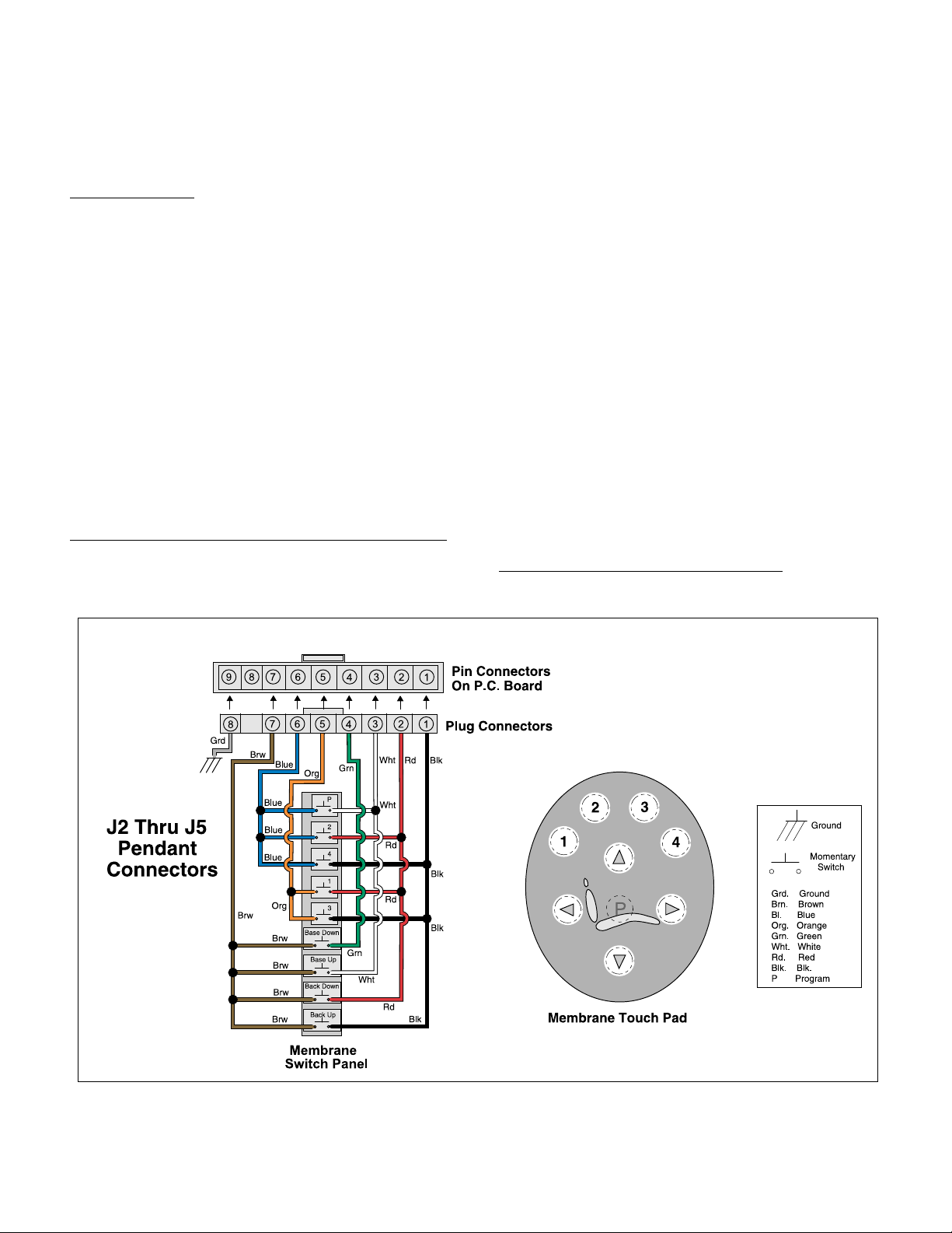
J1 thru J5 Pendants .................................. 5-8
J-Box Wiring Diagram ............................... 5-9
Console / Accessory Wiring Diagram ..... 5-10
Base Up Hydraulic Function ................... 5-11
Base Down Hydraulic Function............... 5-12
Back Up Hydraulic Function.................... 5-13
Back Down Hydraulic Function ............... 5-14
(*) Indicates that there has been a serial number break for the illustration
and that there are additional point page(s) following the original page.
© Midmark Corporation 2000 SF-1620 Page i Printed in U.S.A.
Rev. 10/12
Page 4

TABLE OF CONTENTS
Go To Table Of Contents
SECTION VI PARTS LIST
6.1 Introduction ................................................. 6-1
6.2 Description Of Columns ............................... 6-1
6.3 Torque Specifications And Important
Assembly Notes ........................................... 6-1
Pictorial Index (UltraComfort ®) .................. 6-2
Pictorial Index (UltraTrim) ............................ 6-3
Silhouette Upholstery (UltraComfort ®) ...... 6-4
Ultraleather Upholstery (UltraComfort ®).... 6-5
Silhouette Upholstery (UltraTrim)................. 6-6
Ultraleather Upholstery (UltraTri m) .............. 6-7
Double Articulating Headrest ......................6-8*
Magnetic Headrest ....................................... 6-9
Covers .......................................................6-10*
Base Components ..................................... 6-11
Seat Components ..................................... 6-12*
Brake Components .................................... 6-13
Back Components (UltraComfort ®) ......... 6-14
Back Components (UltraTrim) ................... 6-15
Hydraulic Components.............................. 6-16*
Hoses and Fittings ..................................... 6-17
Electrical Components..............................6-18*
Foot Control ............................................... 6-19
L/R and Console Components.................. 6-20*
Remote Mounted Chair Control ................ 6-21*
COMMENTS ............................................................. 7-1
FAX ORDER FORM.................................................. 7-2
(*) Indicates that there has been a serial number break for the illustration
and that there are additional point page(s) following the original page.
© Midmark Corporation 2000 SF-1620 Page ii Printed in U.S.A.
Rev. 10/12
Page 5
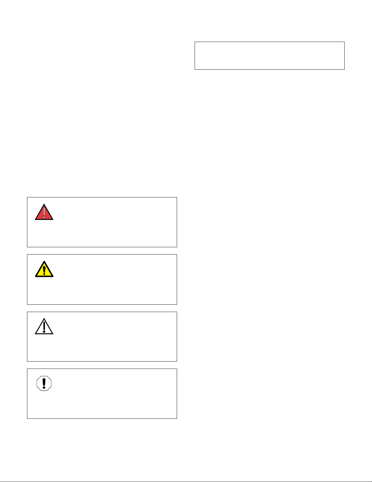
TABLE OF CONTENTS
Go To Table Of Contents
General Safety Instructions
Safety First: The primary concern of Midmark Corporation is that this chair is maintained with the safety
of the patient and staff in mind. To assure that services
and repairs are completed safely and correctly, proceed
as follows:
(1) Read this entire manual before performing any
services or repairs on this chair.
(2) Be sure you understand instructions contained
in this manual before attempting to service or
repair chair.
Safety Alert Symbols
Throughout this manual are safety alert symbols that
call attention to particular procedures. These items are
used as follows:
DANGER
A DANGER is used for an imminently
hazardous operating procedure, practice, or condition which, if not correctly followed,
will result in loss of life or serious personal
injury.
NOTE
A NOTE is used to amplify an operating procedure,
practice or condition.
Warranty Instructions
Refer to Midmark “Limited Warranty” printed in the
Installation and Operation Manual for warranty information. Failure to follow guidelines listed below will void
the warranty and/or render the Dental Chair unsafe for
operation.
• In event of a malfunction, do not attempt to use
dental chair until necessary repairs have been
made.
• Do not attempt to disassemble chair, replace malfunctioning or damaged components, or perform
adjustments unless you are one of Midmark’s
authorized service technicians.
• Do not substitute parts of another manufacturer
when replacing inoperative or damaged components. Use only Midmark replacement parts.
WARNING
A WARNING is used for a potentially
hazardous operating procedure, practice, or condition which, if not correctly followed,
could result in loss of life or serious personal
injury.
CAUTION
A CAUTION is used for a potentially haz-
ardous operating procedure, practice, or
condition which, if not correctly followed, could result
in minor or moderate injury. It may also be used to
alert against unsafe practices.
EQUIPMENT ALERT
An EQUIPMENT ALERT is used for an
imminently or potentially hazardous operating procedure, practice, or condition which, if not
correctly followed, will or could result in serious, moderate, or minor damage to unit.
© Midmark Corporation 2000 SF-1620 Page iii Printed in U.S.A.
Page 6

Go To Table Of Contents
Page 7

SECTION I
Go To Table Of Contents
GENERAL INFORMATION
SECTION I
GENERAL INFORMATION
1.1 Scope of Manual
This manual contains detailed troubleshooting, scheduled maintenance, maintenance, and service instructions for the Midmark Dental Chair. This manual is
intended to be used by Midmark’s authorized service
technicians.
1.2 How to Use Manual
A. Manual Use When Performing Scheduled Mainte-
nance.
(1) Perform inspections and services listed in
Scheduled Maintenance Chart (Refer to
para 3.1).
(2) If a component is discovered to be faulty or out
of adjustment, replace or adjust component in
accordance with maintenance / service instructions (Refer to para 4.1).
B. Manual Use When Unit Is Malfunctioning And
Cause Is Unknown.
(1) Perform an operational test on chair (Refer to
para 2.1).
(2) Perform troubleshooting procedures listed in
Troubleshooting Guide (Refer to para 2.2).
(3) If a component is discovered to be faulty or out
of adjustment, replace or adjust component in
accordance with maintenance / service instructions (Refer to para 4.1).
C. Manual Use When Damaged Component Is Known.
(1) Replace or adjust component in accordance
with maintenance / service instructions (Refer
to para 4.1).
1.3 Description Of Midmark Dental Chair
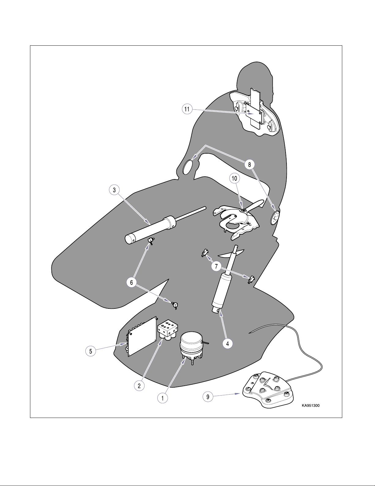
A. General Description (See Figure 1-1).
The Midmark Chair is a dental operating chair designed
for the general dentistry market. The chair is hydraulically positioned using a hydraulic pump, back, base cylinders and solenoid valve unit that are activated by
depressing either the desired membrane or foot switch.
B. Major Serviceable Components (See Figure 1-1).
Hydraulic Motor Pump (1, Figure 1-1)
Motor Pump provides hydraulic pressure to system and
works with the solenoid valves, check valves, and throttle valves to operate Back and Base cylinders.
A capacitor, mounted near the reservoir, provides start
and run power.
Motor is for intermittent
will cause motor to overheat, causing internal thermal
overload to open, removing power from motor. Normal
cool off period for thermal overload to reset is approximately 10 minutes.
Solenoid Valve Unit (2, Figure 1-1)
Solenoid Valve Unit consist of Back Up, Back Down,
Base Up, and Base Down Solenoid valves.
Four manually set Throttle Valves (TV1, TV2, TV3, and
TV4) control flow of hydraulic fluid during various functions.
Two Check Valves (CV1 and CV2) prevent fluid from
back flowing through Base Up and Back Up Solenoid
Val ves.
A Pressure Relief Valve protects the system should
higher then normal pressure occur during operation.
Back Hydraulic Cylinder (3, Figure 1-1)
Back Hydraulic Cylinder is a single-acting cylinder. During Back Up operation the Motor Pump is operating to
create hydraulic pressure required to raise the cylinder.
During Back Down function Motor is not
cylinder operates by pressure created by equipment
and patient weight to lower Back section.
Base Hydraulic Cylinder (4, Figure 1-1)
Base Hydraulic Cylinder is a single-acting cylinder. During Base Up operation the Motor Pump is operating to
create hydraulic pressure required to raise the cylinder.
During Base Down function Motor is not
cylinder operates by pressure due to equipment and
patient weight to lower Base section.
operation. Continuous operation
running and the
running and
© Midmark Corporation 2000 SF-1620 Page 1-1 Printed in U.S.A.
Page 8
SECTION I
Figure 1-1. Component Location
Go To Table Of Contents
GENERAL INFORMATION
© Midmark Corporation 2000 SF-1620 Page 1-2 Printed in U.S.A.
Page 9

SECTION I
Go To Table Of Contents
GENERAL INFORMATION
P.C. Board w/ Fuses (5, Figure 1-1)
Printed Circuit Board contains 115 VAC or 230 VAC line
voltage, 12 VDC, and 5 VDC plug connectors, 12 VDC
supply transformer for control circuitry, Pump, Base and
Back control relays, two 6.5 amp (115 VAC) or 3.15 amp
(230 VAC) line input fuses, one 100 mA fuse for 115
VAC Input to P.C. Board Transformer,
RV1 Surge Protector for over-voltage spikes, Program
switch (SW1), Calibration Button (SW2), and main
Microprocessor (U6).
Back and Base Positioning
Potentiometers (6, Figure 1-1)
Positioning Potentiometers provide P.C. board with
information, thru voltage change, on the positions of
Base and Back sections during operation.
P.C. board, during calibration mode, uses the potentiometers to determine where end of travel points are for
Base and Back. It stores this information and, while
monitoring voltage output of potentiometers, prevents
chair from reaching extreme ends of travel.
Output voltage from potentiometers allows P.C. board,
thru use of program and positioning buttons, to store
desired chair positions in P.C. board memory.
After a position has been programmed, depressing that
programmed button (1 thru 4) will automatically move
the chair to the position.
Safety Bail Limit Switches (7, Figure 1-1)
Two Safety Bail Limit Switches are normally closed
(N.C.) switches located on patient’s
parallel arms.
During chair’s descent, if bottom lift arm cover contacts
an obstruction, cover will depress switch actuator(s) of
Safety Bail Limit Switch(es). The normally closed contacts open, removing power from Base Down and Back
Down solenoid coils at plug connectors J17 (4 & 5) and
J18 (4 & 5) on PC board. Base Up and Back Up will
continue to work.
When the obstruction is removed, the switch(es) return
to the N.C. position. To continue a function, depressing
that function button allows chair to continue its operation.
right and left side
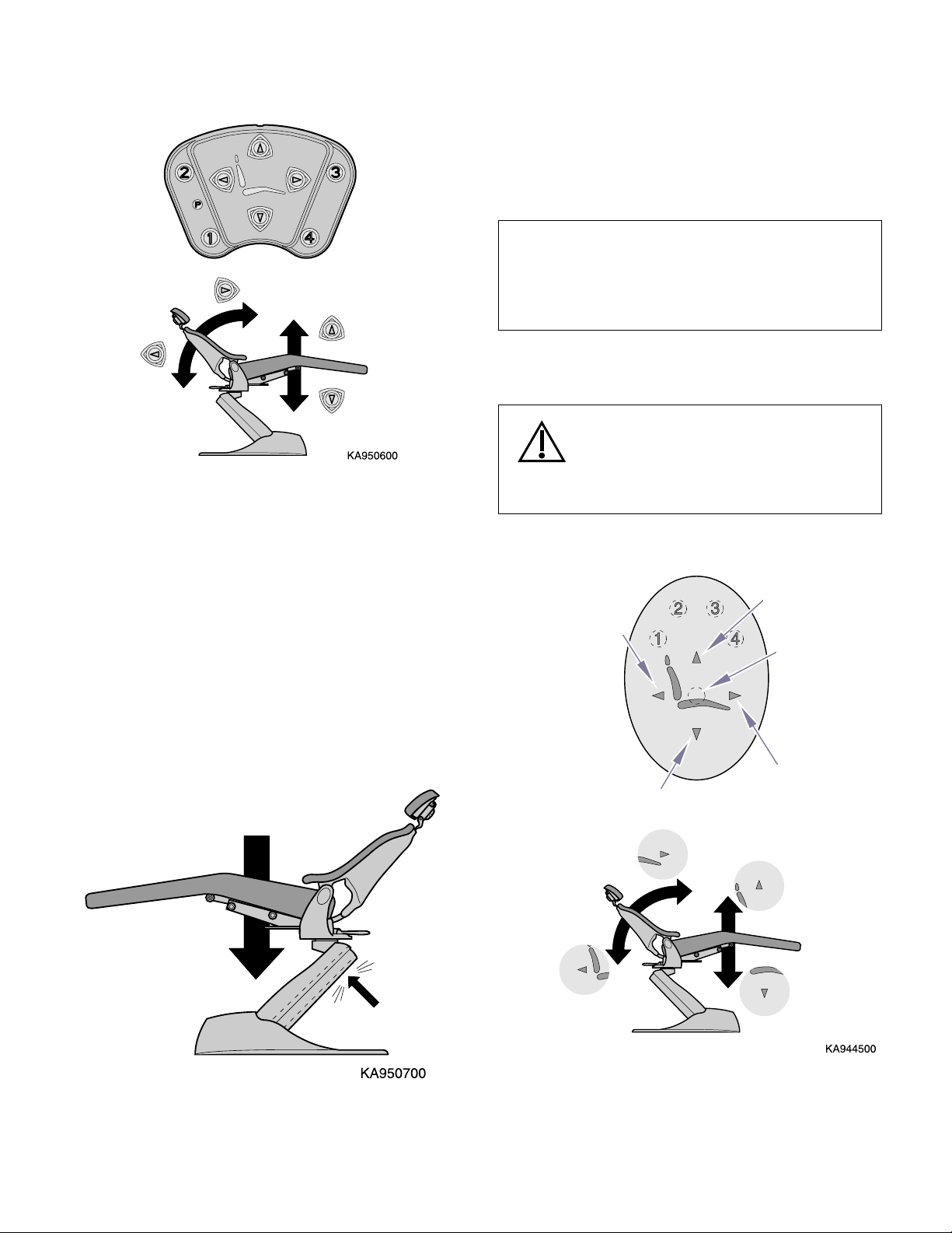
Membrane Touch Pads (8, Figure 1-1)
Membrane touch pads are located on both sides of the
chair or on consoles of the delivery systems. Operate
the chair by depressing one of four directional arrow
buttons that corresponds to back or seat graphic.
Depressing one of the four program buttons (1 thru 4)
allows for chair movement to a predetermined setting.
The functions can be stopped by momentarily depressing any switch on the touch pads or foot control.
A hidden switch, located in the center of the directional
arrows on the pad, is for setting programmed positions.
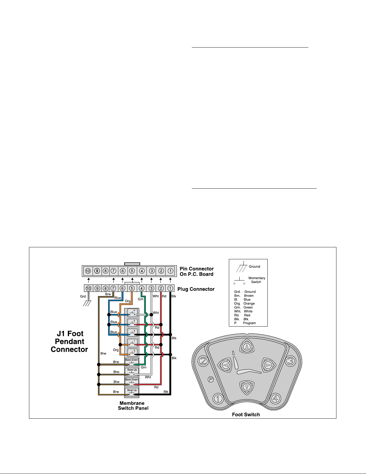
Foot Switch (9, Figure 1-1)
Foot Switch consist of four directional arrow buttons,
four numbered program position buttons and a button,
designated by the letter “P”, for programming.
Depressing one of the four directional arrow buttons
that corresponds to the back or seat graphic moves
chair in that direction.
Depressing one of the four program buttons (1 thru 4)
allows for chair movement to a predetermined setting.
Functions can be stopped by momentarily depressing
any switch on the touch pads or foot control.
The button, with the letter “P”, is for setting programmed
positions.
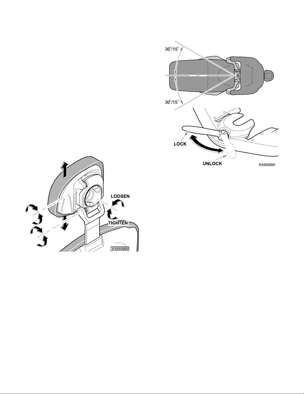
Rotational Seat Lock (10, Figure 1-1)
The chair seat will rotate 30° each way from center-line
for a stand-alone and console chair. For a L / R chair it
will rotate 15°. To release the rotational lock, rotate the
handle toward the patient’s right side.
To engage the rotational lock, rotate the handle toward
the patient’s left side.
Headrest Locking Assembly (11, Figure 1-1)
Headrest height can be changed by pulling out or pushing in on headrest. Tension of headrest locking assembly is pre-set at factory but can be adjusted if required.
© Midmark Corporation 2000 SF-1620 Page 1-3 Printed in U.S.A.
Page 10
SECTION I
RH Touch Pad Shown.
Figure 1-2. Membrane Touch Pads.
Go To Table Of Contents
GENERAL INFORMATION
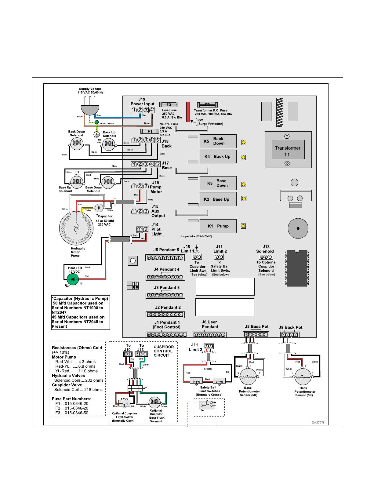
C. Theory of Operation (Refer to Figure 1-4 and
Section V for wiring diagram, electrical schematics and hydraulic layouts).
Electrical Power:
Line voltage is supplied to chair’s Main PC Board thru
power cord.
F1, F2, and F3 replaceable fuses, protect P.C. Board
from excessive current draw.
RV1 Surge Suppressor, protects P.C. board from voltage spikes by partially blocking electrical flow until supply voltage returns to a normal value.
A transformer along with voltage regulators on PC circuit board reduces line voltage to 12 and 5 VDC. This
provides power to operate the circuitry on PC circuit
board, limit switches, membrane switch panel, and foot
control.
Relays K1 thru K5 on P.C. board are for line voltage
operation of Solenoid Valves and Motor Pump.
LED’s, next to the specific relay, lights when that relay is
operated.
Operation of Membrane Switch Panels (Figure 1-2):
PC circuit board supplies 5 VDC to one side of each
normally open (N.O.) switches in membrane switch
panel. Pressing a membrane switch, closes contacts,
completing a circuit, allowing a signal to return to PC
circuit board, activating the function selected.
Functions available are Back Up and Down, Base Up
and Down, Programmed settings, 1 thru 4, and a Programming button “P”.
Program Function (Figure 1-2):
Using the Directional buttons, place chair in a desired
position. Press Program (P) button, unmarked button in
middle of Directional buttons. There is a short audible
beep after which you have three (3) seconds to depress
the desired Program Position button (1,2, 3, or 4). When
the Position button is depressed, three audible beeps
are sounded indicating the position has been stored.
Pressing the Position button will bring the chair to the
position that was programmed.
Manual Override Function (Figure 1-2):
Pressing and holding the Program (P) button while
pressing a Directional button by-passes the feedback
coming from the back and base potentiometers. This
allows for operation of the chair should a potentiometer
malfunction. This should only be used should a patient
be on the chair to allow for safe exit. Service should be
called to repair malfunction.
Operation of Foot Control (Figure 1-3):
PC circuit board supplies 5 VDC to one side of each of
© Midmark Corporation 2000 SF-1620 Page 1-4 Printed in U.S.A.
Page 11
SECTION I
Figure 1-3. Foot Control
Go To Table Of Contents
GENERAL INFORMATION
the normally open (N.O.) switches in foot switch. Pressing one of the switches, closes the contacts, completing
a circuit, allowing a signal to return to PC circuit board,
activating the function selected.
Functions available are Back Up and Down, Base Up
and Down, Programmed settings 1 thru 4, and a Programming button “P”. Should a malfunction occur the
Manual Override function can be used.
Program Function (Figure 1-3):
Using the Directional buttons, place chair in a desired
position. Press Program (P) button. There is a short
audible beep after which you have three (3) seconds to
depress the desired Program Position button (1,2, 3, or
4). When a Position button is depressed, three audible
beeps are sounded indicating the position has been
stored.
Pressing the Position button will bring the chair to the
position that was programmed.
Manual Override Function (Figure 1-3):
Pressing and holding the Program (P) button while
pressing a Directional button by-passes the feedback
coming from the back and base potentiometers. This
allows for operation of the chair should a potentiometer
malfunction. This should only be used should a patient
be on the chair to allow for safe exit. Service should be
called to repair malfunction.
Back Up Function Operation (Figure 1-4):
Depressing and holding one of the Back Up directional
button completes a circuit to the PC board.
On the PC board, K4 contacts close supplying line voltage to connector J18, pins 2 and 3, to the Back Up solenoid coil, energizing the coil, opening the hydraulic
valve.
At the same time, K1 contacts close supplying line voltage to connector J16, pins 2 and 3, to the hydraulic
motor pump, energizing the pump.
During the Back Up function, the Back Potentiometer,
connected to J9 connector, signals movement of the
Back section.
During normal operation, when the potentiometer
reaches the calibrated position, just before the extreme
end of travel, the signal it sends back to the PC board
tells the board to open K1 and K4 contacts removing
power from the Back Up solenoid valve and hydraulic
pump motor.
Back Down Function Operation (Figure 1-4):
Depressing and holding one of the Back Down directional button completes a circuit to the PC board.
On the PC board, K5 contacts close supplying line voltage to connector J18, pins 4 and 5, to the Back Up solenoid coil, energizing the coil, opening the hydraulic
valve.
© Midmark Corporation 2000 SF-1620 Page 1-5 Printed in U.S.A.
Page 12
SECTION I
LED
LED
LED
LED
LED
LS1
SW1
(Prog.)
Main P.C.
Board
SW2
(Calib.)
U6
ON
OFF
Dental Chair
115 VAC
NC
C
NC
C
Limit Switch Layout
C
NO
NC
1122443
3
NO
C
For Pendant (J1 thru J6)
Connectors Refer to
Pendant P.C. Schematics
NOTE:
For Harness Part Numbers
Refer to Section 5.
(Remove when
installing cuspidor)
Figure 1-4. Main P.C. Board and Related Components
Go To Table Of Contents
GENERAL INFORMATION
During the Back Down function, the Back Potentiometer, connected to J9 connector, signals movement of the
Back section. During normal operation, when the potentiometer reaches the calibrated position, just before the
extreme end of travel, the signal it sends back to the PC
board tells the board to open K5 contacts and remove
power to the Back Down solenoid valve.
© Midmark Corporation 2000 SF-1620 Page 1-6 Printed in U.S.A.
Rev. 1/14
Page 13

SECTION I
Go To Table Of Contents
GENERAL INFORMATION
Base Up Function Operation (Figure 1-4):
Depressing and holding one of the Base Up directional
button completes a circuit to the PC board.
On the PC board, K2 contacts close supplying line voltage to connector J17, pins 2 and 3, to the Base Up
solenoid coil, energizing the coil, opening the hydraulic
valve.
At the same time, K1 contacts close supplying line voltage to connector J16, pins 2 and 3, to the hydraulic
motor pump, energizing the pump.
During the Base Up function, the Base Potentiometer,
connected to J8 connector, signals movement of the
Base section. During normal operation, when the potentiometer reaches the calibrated position, just before the
extreme end of travel, the signal it sends back to the PC
board tells the board to open K1 and K2 removing
power to Base Up solenoid valve and hydraulic pump
motor.
Base Down Function Operation (Figure 1-4):
Depressing and holding one of the Base Down directional button completes a circuit to the PC board.
On the PC board, K3 contacts close supplying line voltage to connector J17, pins 4 and 5, to the Base Down
solenoid coil, energizing the coil, opening the valve.
During the Base Down function, the Base Potentiometer, connected to J8 connector, signals movement of the
Base section. During normal operation, when the potentiometer reaches the calibrated position, just before the
extreme end of travel, the signal it sends back to the PC
board tells the board to open K3 contacts and remove
power to the Base Down solenoid valve.
Safety Bail Limit Switches (Figure 1-4):
During Base or Back Down operations, as chair is
descending, should bottom lift arm cover contact an
obstruction, one or both normally closed (N.C.) Safety
Bail Limit Switches, located beneath cover, will open.
Power is removed from Base and Back solenoid valves,
closing the valves, stopping descent of both base and
back. Base Up and Back Up functions will continue to
work.
Removing the obstacle, returns switch contacts to
closed position.
Press the desired directional or program button to
resume operation.
1.4 Standard Torque Specifications
The following standard torque specifications in
Table 1-1 apply to the hardware used on the unit unless
otherwise listed elsewhere in the service procedures or
parts illustrations.
Table 1-1. Torque Specifications
Hardware Size* Torque Values
#6 .............................. 11 to 21 inch-lbs. (1.2 to 2.3 N•M)
#8 .............................. 20 to 30 inch-lbs. (2.2 to 3.3 N•M)
#10 ............................ 32 to 42 inch-lbs. (3.6 to 4.8 N•M)
1/4 inch ..................... 75 to 85 inch-lbs. (8.5 to 9.6 N•M)
5/16 inch ...................18 to 22 ft.-lbs. (24.4 to 29.8 N•M)
3/8 inch .....................31 to 35 ft.-lbs. (42.0 to 47.5 N•M)
1/2 inch .....................50 to 60 ft.-lbs. (67.8 to 81.4 N•M)
* All hardware should be grade 5 or above.
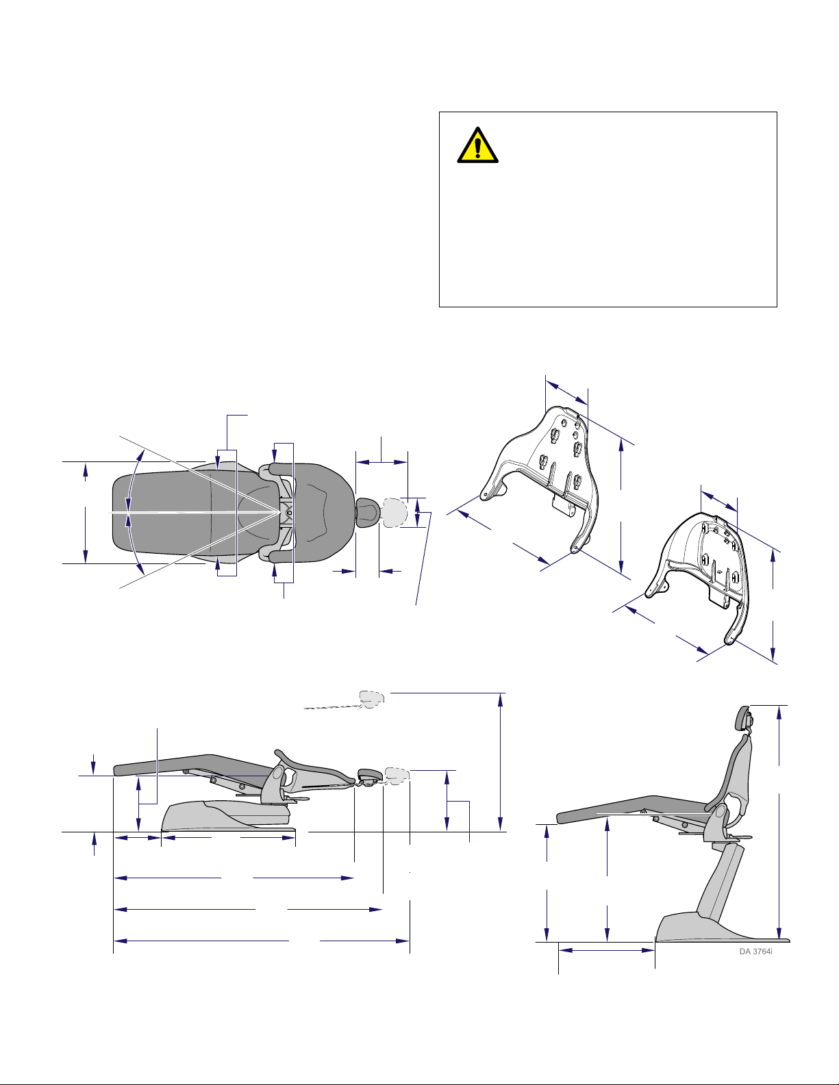
1.5 Specifications
Factual data for the Midmark Dental Chair is provided in
Table 1-2. Also, see Figure 1-5.
Table 1-2. Specifications
Description Data
Maximum Patient Weight.......................300 lbs (136 kg)
Weight of a Unit:
Without Shipping Carton
Chair Only ......................................290 lbs (132 kg)
Chair (L / R or Console) 310 lbs (141 kg)
With Shipping Carton
Chair Only ......................................350 lbs (159 kg)
Chair (L / R or Console)l.................370 lbs (168 kg)
Hydraulic Fluid Requirements
System Capacity ........................... 1 Quart (950 ml)
Type of Hydraulic Fluid ........................... ISO VG 32
Electrical Requirements:..................... 115 VAC +/-10%,
5A, 60 HZ,
single phase
or
230 VAC +/-10%,
2.5A, 50/60 HZ,
single phase
Fuse Rating*:
F1 Line Fuse, 115 VAC ................. T6.3 AL, 250 VAC
5 x 20mm, Type Slo-Blo
or
© Midmark Corporation 2000 SF-1620 Page 1-7 Printed in U.S.A.
Rev. 10/12
Page 14
SECTION I
29" max.
(73.7 cm)
27.5" max.
(69.9 cm)
58" max.
(147.3 cm)
22"
(55.9 cm)
25.8"
(65.6 cm)
11.2"
(28.4 cm)
20.7"
(52.5 cm)
25.9"
(65.8 cm)
10.3"
(26.1 cm)
20.5"
(52.7 cm)
8"
(20.3 cm)
20"
(50.8 cm)
8.75"
(22.2 cm)
27"
(68.6 cm)
27 .5"
(69.8 cm)
23"
(58.4 cm)
15o LR and Console
30
o
Chair Only
33" max. (83.8 cm)
w/ Back Level
30" max. (76.0 cm)
w/ Back Full Down
36"
(91.4 cm)
16.0" min.
(40.6 cm)
67"
(170.2 cm)
75"
(190.5 cm)
87"
(221.0 cm)
19.0" min. (48.2 cm)
w/ Back Level
16.25" min. (41.3 cm)
w/ Back Full Down
15"
(38.1 cm)
16.5"
(41.9 cm)
Ultra-Trim
Back
Ultra-Comfort
Back
Figure 1-5. Specifications
Go To Table Of Contents
GENERAL INFORMATION
F1 Line Fuse, 230 VAC.................T3.15 AL, 250 VAC
5 x 20mm, Type Slo-Blo
F2 Line Fuse, 115 VAC ..................T6.3 AL, 250 VAC
5 x 20mm, Type Slo- Blo
or
F2 Line Fuse, 230 VAC.................T3.15 AL, 250 VAC
5 x 20mm, Type Slo-Blo
F3 Transformer Fuse
115 VAC / 230 VAC ... T0.10 AL / T0.05 AL, 250 VAC
5 x 20mm, Type Slo-Blo
(*Fuses are located on P.C. Board.)
Duty Cycle ................................... Intermittent Operation
(30 seconds on / 5 minutes off,
motor run time)
WARNING
Should it be necessary to transport the
chair, its position is critical to ensure
safety. Before attempting to move / transport
chair, it must be lowered to its minimum height
and locked in place at 0° rotation (install shipping
bolt - refer to step 7 on page A-1 of the Installation Guide, Module A). NOTE: Midmark strongly
recommends disassembling any accessory arms
(unit, light, etc.) from chair before attempting to
move / transport an entire operatory.
© Midmark Corporation 2000 SF-1620 Page 1-8 Printed in U.S.A.
Rev. 11/8/12
Page 15
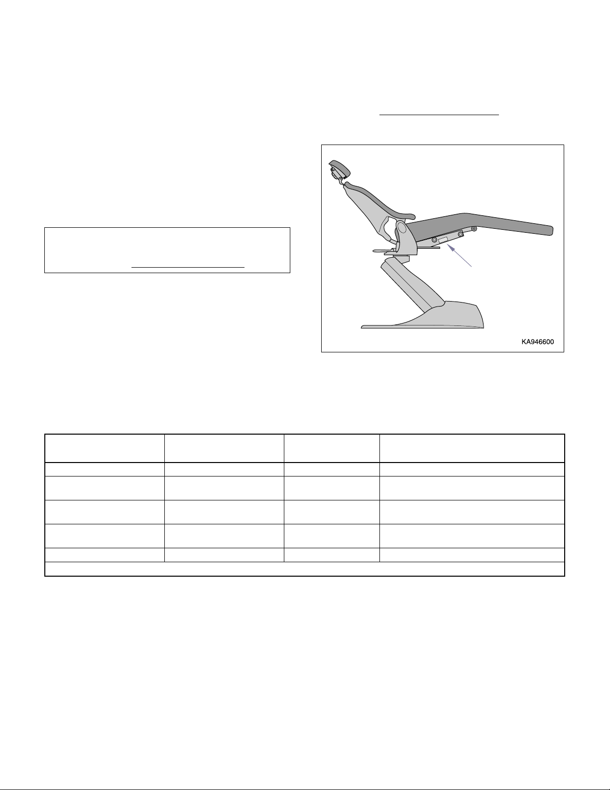
SECTION I
Figure 1-6. Model Number / Serial Number Location
Model / Serial
Number
Go To Table Of Contents
GENERAL INFORMATION
1.6 Parts Replacement Ordering
If replacement part(s) are required, order part(s) directly
from factory as follows:
(1) Refer to Figure 1-6 to determine location
of model number and serial number of chair
and record this data.
Refer to Parts List to determine item numbers
of parts, part numbers, descriptions, and quantities needed and record this data (Refer to
para 6.1).
NOTE
To assure expedient service and correct parts you
must have correct Model and Serial Number
of chair.
(2) Determine installation date of chair and record
this data. Call Midmark (1-800 643-6275) and
ask for Technical Service Department. Please
have Model and Serial Number
of chair.
Table 1-3. Special Tool List
Description of Special Tool
Multimeter * Commercially Available Any Type Used to perform continuity and voltage checks.
Scissor Jack (capable of lifting a
minimum of 1000 lbs. [454 kg])
Jack Stands (Qty. 2) (capable of
supporting 1000 lbs. [454 kg])
Jumper wire with insulated clips Made up by technician N/A For jumpering various test points during trouble-
Torque Wrench * Commercially Available Any Type Used to tighten nuts or screws to specified values.
Manufacturer’s
Name / Address / Phone
Commercially Available Any Type Used to elevate Back section when hydraulic Base
Commercially Available Any Type Used to support chair top when hydraulic base cyl-
* Tool should be calibrated annually to ensure proper specifications are met.
Manufacturer’s
Part Number
Purpose of Special Tool
cylinder or motor pump is malfunctioning.
inder or motor pump is being worked on.
shooting.
© Midmark Corporation 2000 SF-1620 Page 1-9 Printed in U.S.A.
Rev. 4/01
Page 16

SECTION I
Go To Table Of Contents
GENERAL INFORMATION
© Midmark Corporation 2000 SF-1620 Page 1-10 Printed in U.S.A.
Page 17

BACK
DOWN
PROGRAM
BUTTON
SEAT
UP
SEAT
DOWN
BACK
UP
RH Touch Pad Shown.
Figure 2-1. Operational Test
SECTION II
Go To Table Of Contents
TESTING AND TROUBLESHOOTING
2.1 Operational Test
In order to effectively diagnose a malfunction of chair, it
may be necessary to perform an operational test as fol-
lows:
WARNING
Refer to the Operator’s Manual for com-
plete instructions on operating the
chair. Failure to do so could result in personal
injury.
NOTE
The Operational Test, for the most part, only
describes what should happen when chair is operated. If the chair does something other than
described, a problem has been discovered. Refer to
Troubleshooting Guide to determine cause of problem and its correction.
SECTION II
TESTING AND TROUBLESHOOTING
WARNING
When performing various checks with
chair plugged in and covers off use
extreme care to prevent accidental electrical
shock. Failure to comply could cause severe
injury.
(1) Plug chair power cord into a grounded, non-iso-
lated, correctly polarized outlet, that has proper
voltage for chair.
(2) Depress Back Up, Back Down, Base Up, and
Base Down buttons on membrane switch panel
(Refer to Figure 2-1).
Observe. Chair should move in direction corresponding to button being depressed. Hydraulic
motor pump and cylinders should run quietly.
Movement should be smooth and match speed
and range of motions listed below:
Chair Speeds (±1 second w/ 180 lbs [82 kg]
load on chair)
Back Up to Back Down...................15 seconds
Back Down to Back Up...................15 seconds
Base Up to Base Down ..................15 seconds
Base Down to Base Up ..................15 seconds
See Figure 1-5 for max. and min. heights.
(3) Place a 300 lbs (136 kgs) weight on center of
seat section of chair.
Observe. Seat section should not drift downward under weight.
(4) Depress Base Up and Base Down buttons on
membrane switch panel.
Observe. Chair base should lift weight steadily
and without excessive noise.
(5) Remove weights from chair. Then, place a 100
lbs (45.4 kgs) weight on center of back section
of chair (with back section at approximately 45º
above horizontal).
© Midmark Corporation 2000 SF-1620 Page 2-1 Printed in U.S.A.
Rev. 8/01
Page 18
SECTION II
Figure 2-2. Headrest
Figure 2-3. Rotational Lock
Go To Table Of Contents
TESTING AND TROUBLESHOOTING
(6) Depress Back Up and Back Down buttons on
membrane switch panel.
Observe. Back should lift weight steadily and
without excessive noise.
(7) Remove weights from chair.
(8) Run Back Up function all the way up and Base
Down function all the way down.
(9) Slide headrest in and out stopping at different
positions. Push gently against headrest at
each position (Refer to Figure 2-2).
Observe. Headrest should not require excessive force to position. When in a position, headrest should not move when a slight pressure is
applied.
(10) If chair has Articulating Headrest, loosen knob,
move headrest to different positions.
Observe. Headrest should move smoothly
without requiring excessive force.
(11) Tighten knob.
Observe. Headrest should remain in position
when force is applied.
Observe. Chair top should rotate smoothly
and easily; not requiring excessive force. The
chair top should be able to be rotated from stop
to stop which is 60°
or 30° in each direction
from centerline of chair. L / R and console
chairs will rotate 30° and 15°.
(13) Tighten Rotation Lock lever to locked position.
Attempt to rotate chair top.
Observe. Chair top should not be able to be
rotated when Rotation Lock lever is engaged.
(14) Depress Back Up, Back Down, Base Up, Base
Down buttons on foot control (Refer to
Figure 2-4).
Observe. When each of the buttons on foot
control are depressed, appropriate function
should activate.
(12) Loosen Rotation Lock lever and rotate chair top
until it hits a stop. Then rotate chair top in
opposite direction until it hits a stop. (Refer to
Fig. 2-3).
© Midmark Corporation 2000 SF-1620 Page 2-2 Printed in U.S.A.
Rev. 10/12
Page 19
(15) Depress Base Down membrane or foot switch.
Figure 2-4. Foot Control
Figure 2-5. Safety Bail Limit Switches.
PROGRAM
BUTTON
BACK
DOWN
SEAT
UP
BACK
UP
SEAT
DOWN
RH Touch Pad Shown.
Figure 2-6. Manual Override
Go To Table Of Contents
As chair descends, push upward on bottom lift
arm cover until one or both of the Safety Bail
Limit switches operate (Refer to Figure 2-5).
SECTION II
TESTING AND TROUBLESHOOTING
(16) Check Manual Override using touchpad mem-
brane switch or foot control. Depress and hold
Program (P) button and then depress desired
Manual positioning button(s) (Refer to
Figure 2-6 ).
NOTE
The Program button on Membrane Touchpads is
located directly above Seat graphic. On Foot Control
it is located on left side and designated with the letter
“P”.
Observe. Chair should move to desired position as long as buttons are being depressed.
CAUTION
This procedure should be used by the
operator only in case of a chair malfunction
should a patient be on chair. This permits positioning
the chair to allow a patient to safely exit chair.
Observe. When bottom lift arm cover contacts
and operates Safety Bail Limit switch(es) chair
should immediately stop its descent.
Releasing bottom lift arm cover, returns Safety
Bail Limit switch(es) to normally closed position.
Operating Base Down membrane or foot switch
will cause chair to descend again.
© Midmark Corporation 2000 SF-1620 Page 2-3 Printed in U.S.A.
Rev. 8/01
Page 20
SECTION II
PROGRAM
POSITION
RECALL
BUTTONS
(EXAMPLE)
CURRENT CHAIR
POSITION
TO GO TO FAVORITE
PROGRAMMED POSI-
TION #1, DEPRESS
BUTTON “1”
Figure 2-7. Programmed Positions
Figure 2-8. Testing Potentiometer.
Go To Table Of Contents
TESTING AND TROUBLESHOOTING
(17) Check Programmed Positions using touchpads
or foot control. Depress one of the Programmed
recall buttons. The chair should advance to the
position programmed by the user (Refer to
Figure 2-7).
NOTE
Do not attempt to change a programmed position
unless requested by personnel at the Dental office.
(18) Press a Programmed Position again, while
chair is moving to position, press any button on
touchpad or foot control. Chair should stop all
movement.
2.2 Testing Positioning Potentionmeter
A. Check Continuity (Ohms)
WARNING
Unplug chair power cord before remov-
ing covers or working on chair. Failure
to comply could result in personal injury.
(1) Disconnect power to chair and remove uphol-
stery or covers whichever is applicable to
access potentiometer (refer to para 4.16
or 4.17).
(2) Set VOM on resistance (ohms) for a scale that
can read up to 6K ohms.
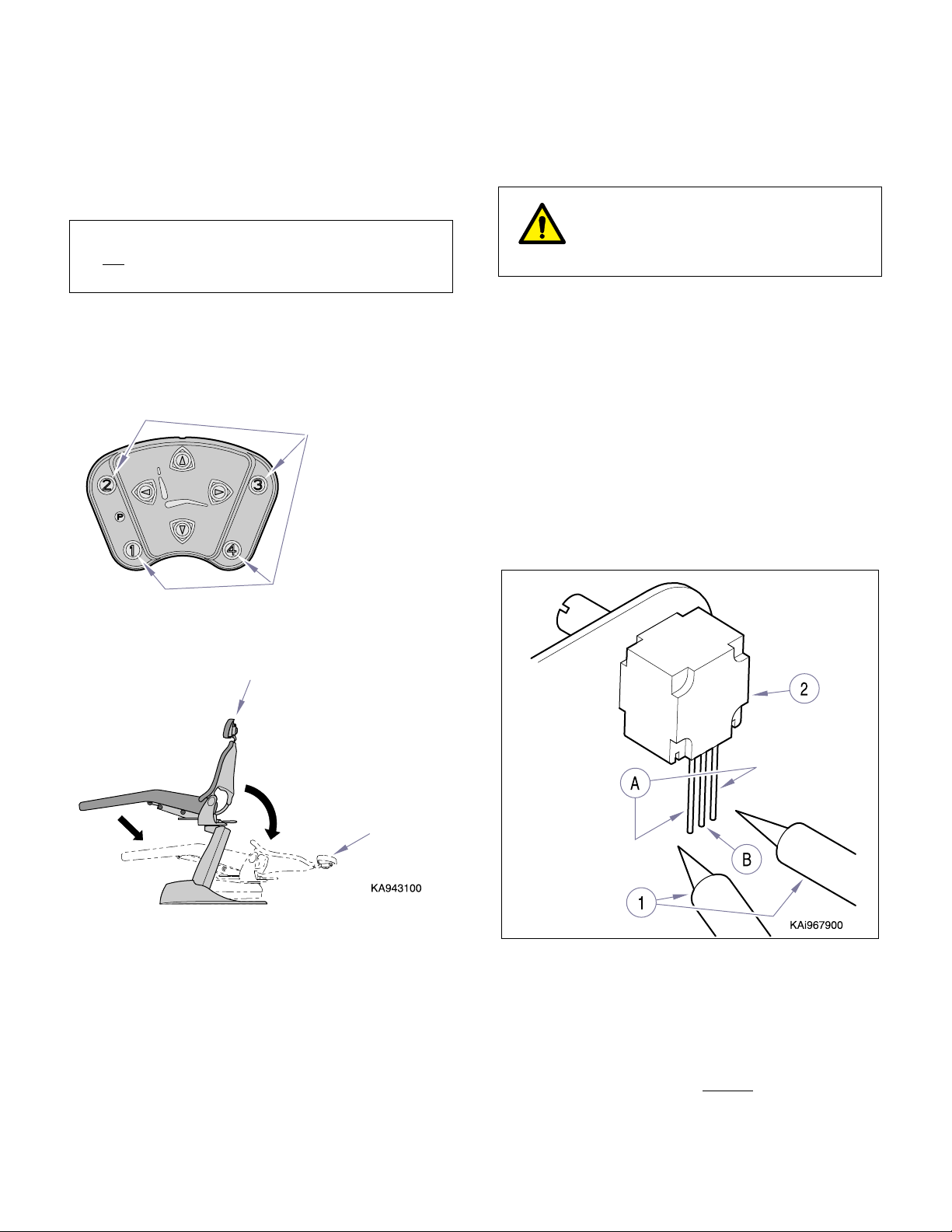
(3) After removing plug connector, place meter
probes (1, Fig. 2-8) on outside leads (A) of
potentiometer (2) for total resistance. Reading
should be 4K to 6K (ohms). Any reading outside this or if no continuity reading is present,
replace potentiometer.
© Midmark Corporation 2000 SF-1620 Page 2-4 Printed in U.S.A.
(4) Move one meter probe to middle lead (B) on
potentiometer.
(5) Slowly rotate potentiometer shaft fully one
direction and then back the other.
Meter should show a smooth
decrease in resistance. If reading becomes
erratic replace potentiometer (refer to para 4.16
or 4.17).
increase or
Page 21
B. Check Voltage (VDC)
Figure 2-9. Testing Potentiometers
Go To Table Of Contents
(1) Remove seat upholstery or appropriate covers
to access back or base potentiometer (refer to
para 4.16 or 4.17).
WARNING
Use caution to prevent electrical shock
with chair plugged into outlet. Electrical
components and connections are exposed.
(2) Plug chair into outlet.
(3) Set meter to read voltage DC on scale appropri-
ate to read approximately 5 VDC.
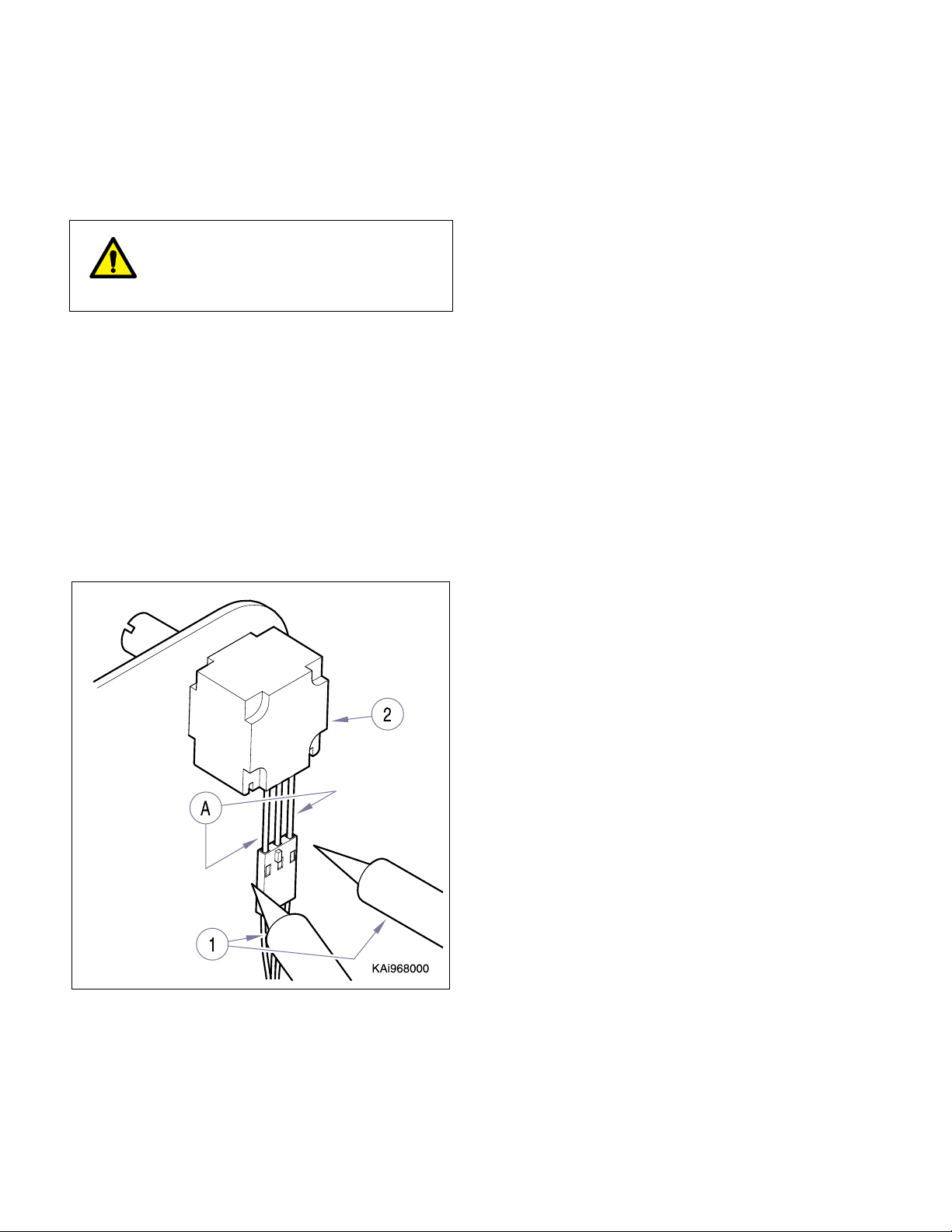
(4) Place meter probes (1, Fig. 2-9) on two outside
leads (A) of potentiometer (2).
Reading should be approximately 5 VDC
(±1 VDC).
If voltage reading is zero (0), leads are broken
in wire harness between potentiometer and P.C.
board or P.C. is not working correctly (Refer to
Troubleshooting Guide, Table 2-1).
SECTION II
TESTING AND TROUBLESHOOTING
© Midmark Corporation 2000 SF-1620 Page 2-5 Printed in U.S.A.
Page 22
SECTION II
Go To Table Of Contents
TESTING AND TROUBLESHOOTING
2.3 Troubleshooting Procedures
Table 2-1 is a Troubleshooting Guide which is used to
determine causes of malfunctions. Refer to diagrams in
Section V to assist in troubleshooting procedures.
Problem Symptom Probable Cause Check Correction
Chair will not operate
when any
selected (from any of the
membrane switch panels or foot control
switches).
function is
When a membrane touchpad or foot control switch is
pressed, nothing happens
and relays cannot be heard
energizing).
Power cord is not plugged
into facility wall outlet.
Facility circuit breaker providing power to chair is
tripped.
Wire connections are loose. Check all wiring connec-
Fuse blown. Remove fuse, F1, F2,
PC circuit board is malfunctioning.
(Note: Incoming Line voltage is present at Power
Input, J19, pins 2 [Blue] & 4
[Brown].)
WARNING
Use extreme caution when testing com-
ponents with chair plugged into outlet.
Line voltage is present. Failure to comply could
result in personal injury.
Check to see if power
cord is plugged in.
Check to see if facility circuit breaker is tripped.
Plug a lamp into wall outlet that chair was plugged
into and see if it operates.
tions from power cord to
PC circuit board. Use a
multimeter to perform
continuity checks on
wires.
Check for line voltage at
plug J19 (line power
input) on pins 2 (blue) &
4 (brown).
and F3 from PC board
and check fuses for continuity.
Check for 12 VDC on
pins 1 & 2 of J14.
Check the LED’s next to
related relay when the
specific function is being
operated.
Plug power cord into facility
wall outlet.
If facility circuit breaker is
tripped, determine what
caused circuit breaker to trip,
correct problem, and then
reset / replace circuit breaker.
Clean any dirty connections.
Tighten any loose connections. Replace any damaged
connections. Refer to Section
V for Schematics.
Replace blown fuse with fuse
of same rating. Refer to Section V for Schematics.
If no 12 VDC is present on J14
replace board.
If LED’s do not light during
function, replace board.
Chair has
functions can be initiated
from membrane touchpad
and foot control.
© Midmark Corporation 2000 SF-1620 Page 2-6 Printed in U.S.A.
Rev. 8/01
power, but no
Plug connector(s) loose or
wire harnesses broken.
SW1 Switch on PC Board is
set in Calibration Mode (both
switches 1 & 2 are ON)
Check visually for damage components and
broken traces on PC
board.
Check all plug connectors and harnesses.
Check settings on SW1
Switch.
If damage is visible replace
board. Refer to para 4.14.
Repair or replace malfunctioning plug connector(s) or wire
harnesses. Refer to Section V
for Schematics.
Place SW1 switch settings in
proper position for user’s
application. Refer to Section V,
SW1 Switch Settings.
Page 23

Problem Symptom Probable Cause Check Correction
Go To Table Of Contents
Chair will not operate
when any
selected (from any of the
membrane touchpads or
foot control switches).
(continued)
function is
Chair has
functions can be initiated
from membrane touchpad
and foot control. (continued)
power, but no
TESTING AND TROUBLESHOOTING
PC Board malfunctioning.
(Note: Incoming Line voltage is present at Power
Input, J19, pins 2 [Blue] & 4
[Brown].)
Check for 12 VDC on
pins 1 & 2 of J14.
Check the LED’s next to
related relay when the
specific function is being
operated.
SECTION II
If no 12 VDC is present on J14
replace board.
If LED’s do not light during
function, replace board.
One or more functions
be initiated from
cannot
membrane touchpad or
foot control.
BACK UP function does
not work.
Some functions can be initiated with membrane
touchpad or foot control,
but at least one cannot.
When any BACK UP button is depressed, chair will
not move (all other functions work).
Switch on Membrane Touchpad or Foot Control is malfunctioning.
Wires Broken or connections
loose .
Capacitor for hydraulic pump
motor weak or bad. (Up
functions would not work)
PC Board malfunctioning.
(Note: Incoming Line voltage is present at Power
Input, J19, pins 2 [Blue] & 4
[Brown].)
BACK or BASE potentiometer plug is loose from specific
potentiometer or wire leads
are broken.
BACK or BASE potentiometer is out of adjustment.
BACK and / or BASE
Potentiometer is damaged.
BACK UP solenoid coil has
an open winding, disconnected or broken lead.
BACK UP solenoid valve
stuck in closed position .
Check visually for damage components and
broken traces on PC
board.
Perform a continuity
check on each N.O. control switch in control
(when switch is pressed,
switch circuit should be
closed) Refer to Section
V for Schematics.
Check all wiring and
related connections
between control switches
and PC circuit board.
Replace capacitor with a
known good capacitor
and check operation.
Check for 12 VDC on
pins 1 & 2 of J14.
Check the LED’s next to
related relay when the
specific function is being
operated.
Check visually for damage components and
broken traces on PC
board.
Check conditions of plug
connectors and wire
leads to potentiometers.
Check adjustment of
BASE and/or BACK
potentiometer(s).
Check potentiometer(s).
Refer to para 2.2.
Check all wires to BACK
UP Solenoid and connections at P.C. Board, pins
2 & 3 on J18. Check
solenoid for an “open”
coil. Refer to Section V
for Schematics.
After checking solenoid
coil , connections, and
wires, assure coil is energized when depressing
BACK UP.
If damage is visible replace
board. Refer to para 4.14.
If control switch does not pass
continuity check, replace control. Refer to para 4.6 or 4.21.
Clean any dirty connections.
Tighten or repair any loose or
damaged connections. Refer
to Section V for schematics.
Replace capacitor. Refer to
para 4.10.
If no 12 VDC is present on J14
replace board.
If LED’s do not light during
function, replace board.
If damage is visible replace
board. Refer to para 4.14.
Connect plug to potentiometer or repair broken leads.
Refer to Section V for schematic.
Adjust potentiometer. Refer to
para(s) 4.16, 4.17 or 4.18.
Replace potentiometer(s).
Refer to para(s) 4.16, 4.17 or
4.18.
Repair wires and / or connections.
Replace Hydraulic Solenoid
Valve Assembly. Refer to para
1
3.
4.
Replace Hydraulic Solenoid
Valve Assembly. Refer to para
4.13.
© Midmark Corporation 2000 SF-1620 Page 2-7 Printed in U.S.A.
Rev. 08/01
Page 24

SECTION II
Go To Table Of Contents
TESTING AND TROUBLESHOOTING
Problem Symptom Probable Cause Check Correction
BACK UP function does
not work. (continued)
BACK DOWN function
does not work.
When any BACK UP button is depressed, chair will
not move (all other functions work). (continued)
When any BACK DOWN
button is depressed, chair
will not move (all other
functions work).
Throttle Valve (TV3) on
Hydraulic Solenoid Valve
Assembly turned in too far or
completely closed.
Hydraulic BACK cylinder
leaking.
Hydraulic Solenoid Valve
Assembly is clogged preventing fluid flow.
BACK potentiometer plug is
loose from potentiometer or
wire leads are broken.
BACK potentiometer is out of
adjustment.
BACK Potentiometer is damaged.
PC Board malfunctioning. When BACK UP is
Safety Bail Limit Switch(es)
harness not installed correctly (loose).
Safety Bail Limit Switch(es)
contacts open due to an
obstruction hitting cover or
Switch(es) malfunctioning,
stuck open
BACK DOWN solenoid coil
has an open winding, disconnected or broken lead.
BACK DOWN solenoid valve
stuck in closed position .
Check position of TV3
Throttle Valve. Refer to
para 4.13 and BACK UP
hydraulic schematic in
Sect. V.
Check for leakage
around hydraulic cylinder and fittings. Check for
excessive fluid returning
to reservoir from Vent
line.
Check for hydraulic fluid
flow to Back Cylinder during operation. Refer to
Section V for Schematics.
Check conditions of plug
connectors and wire
leads to potentiometer.
Check adjustment of
BACK potentiometer.
Check potentiometer.
Refer to para 2.2.
depressed, check LED
next to K4 contacts to
assure it is lit. Check for
line voltage at J18, terminals 2 & 3. Refer to Section V for Schematics.
Check both harness to
assure they are connected tightly.
Safety Bail cover
depressing safety bail
limit switch(es) actuator,
opening contacts on
switch.
Check continuity on
unoperated switch to
assure normally closed
(NC) contacts are closed.
Check all wires to BACK
DOWN Solenoid and
connections at P.C.
Board, pins 4 & 5 on J18.
Check solenoid for an
“open” coil. Refer to Section V for Schematics.
After checking solenoid
coil , connections, and
wires, assure coil is energizes when depressing
BACK DOWN.
Adjust Throttle Valve (TV3).
Refer to para 4.13.
Replace Hydraulic Back Cylinder. Refer to para 4.7.
Replace Hydraulic Solenoid
Valve Assembly. Refer to para
4.13.
Connect plug to potentiometer or repair broken leads.
Refer to Section V for schematic.
Adjust potentiometer. Refer to
para 4.17 or 4.18.
Replace potentiometer. Refer
to para 4.17 or 4.18.
If no voltage is present at J18,
terminals 2 & 3, when BACK
UP is depressed, replace PC
Board. Refer to para 4.14.
Connect harness correctly.
Remove obstruction that
causes cover to actuate limit
switch(es).
Replace Safety Bail Limit
Switch(es). Refer to para
4.19.
Repair wires and / or connec-
ns.
o
ti
Replace Hydraulic Solenoid
Valve Assembly. Refer to para
4.13.
Replace Hydraulic Solenoid
Valve Assembly. Refer to para
4.13.
© Midmark Corporation 2000 SF-1620 Page 2-8 Printed in U.S.A.
Rev. 08/01
Page 25

Problem Symptom Probable Cause Check Correction
Go To Table Of Contents
BACK DOWN function
does not work. (contin-
ued)
BASE UP function does
not work.
When any BACK DOWN
button is depressed, chair
will not move (all other
functions work). (continued)
When any BASE UP button is depressed, chair will
not move (all other functions work).
TESTING AND TROUBLESHOOTING
Throttle Valve (TV4) on
Hydraulic Solenoid Valve
Assembly turned in too far or
completely closed.
Hydraulic Solenoid Valve
Assembly is clogged preventing fluid flow.
Cuspidor Limit Switch contacts open due to cuspidor
hitting obstruction or malfunction.
Cuspidor not installed and
Jumper wire on J10 plug
connector missing.
BACK potentiometer plug is
loose from potentiometer or
wire leads are broken.
BACK potentiometer is out of
adjustment.
BACK Potentiometer is damaged.
PC Board malfunctioning. When BACK DOWN is
BASE UP solenoid coil has
an open winding, disconnected or broken lead.
BASE UP solenoid valve
stuck in closed position .
Throttle Valve (TV1) on
Hydraulic Solenoid Valve
Assembly turned in too far or
letely closed.
p
com
Hydraulic BASE cylinder
leaking.
Check position of TV4
Throttle Valve. Refer to
para 4.13 and BACK
DOWN hydraulic schematic in Sect. V.
Check for hydraulic fluid
flow from Cylinder to
Reservoir during operation. Refer to Section V
for Schematics.
Check if cuspidor is hitting obstruction and/or if
limit switch contacts
are open.
Check for a jumper wire
on P.C. Board plug connector J10.
Check conditions of plug
connectors and wire
leads to potentiometer.
Check adjustment of
BACK potentiometer.
Check potentiometer.
Refer to para 2.2.
depressed, check LED
next to K5 contacts to
assure it is lit. Check for
line voltage at J18, terminals 4 & 5. Refer to Section V for Schematics.
Check all wires to BASE
UP Solenoid and connections at P.C. Board, pins
2 & 3 on J17. Check
solenoid for an “open”
coil. Refer to Section V
for Schematics.
After checking solenoid
coil , connections, and
wires, assure coil is energized when depressing
BASE UP.
Check position of TV1
Throttle Valve. Refer to
para 4.13 and BASE UP
hydraulic schematic in
Section V.
Check for leakage
around hydraulic cylinder and fittings. Check for
excessive fluid returning
to reservoir from Vent
line.
SECTION II
Adjust Throttle Valve (TV4).
Refer to para 4.13.
Replace Hydraulic Solenoid
Valve Assembly. Refer to para
4.13.
Remove obstruction.
Replace Cuspidor limit switch.
Refer to ProCenter® Delivery
System Service & Parts.
Install a jumper wire on terminals 1 & 2, plug connector
J10. Refer to Section V for
Schematics.
Connect plug to potentiometer or repair broken leads.
Refer to Section V for schematic.
Adjust potentiometer. Refer to
para 4.17 or 4.18.
Replace potentiometer. Refer
to para 4.17 or 4.18..
If no voltage is present at J18,
terminals 4 & 5, when BACK
DOWN is depressed, replace
PC Board. Refer to para 4.1.
Repair wires and / or connections.
Replace Hydraulic Solenoid
Valve Assembly. Refer to para
4.13.
Replace Hydraulic Solenoid
Valve Assembly. Refer to para
4.13.
Adjust Throttle Valve (TV1).
Refer to para 4.13.
Replace Hydraulic Base Cylinder. Refer to para 4.7.
© Midmark Corporation 2000 SF-1620 Page 2-9 Printed in U.S.A.
Rev. 08/01
Page 26

SECTION II
Go To Table Of Contents
TESTING AND TROUBLESHOOTING
Problem Symptom Probable Cause Check Correction
BASE UP function does
not work. (continued)
BASE DOWN function
does not work.
When any BASE UP button is depressed, chair will
not move (all other functions work). (continued).
When any BASE DOWN
button is depressed, chair
will not move (all other
functions work).
Hydraulic Solenoid Valve
Assembly is clogged preventing fluid flow.
PC Board malfunctioning. When BASE UP is
Safety Bail Limit Switch(es)
harness not installed correctly (loose).
Safety Bail Limit Switch(es)
contacts open due to an
obstruction hitting cover or
Switch(es) malfunctioning,
stuck open
BASE DOWN solenoid coil
has an open winding, disconnected or broken lead.
BASE DOWN solenoid valve
stuck in closed position.
Throttle Valve (TV2) on
Hydraulic Solenoid Valve
Assembly turned in too far or
completely closed.
Hydraulic Solenoid Valve
Assembly is clogged preventing fluid flow.
Cuspidor Limit Switch contacts open due to cuspidor
hitting obstruction or malfunction.
Cuspidor not installed and
Jumper wire on J10 plug
connector missing.
BASE potentiometer plug is
loose from potentiometer or
wire leads are broken.
Check for hydraulic fluid
flow to Back Cylinder during operation. Refer to
Section V for Schematics.
depressed, check LED
next to K2 contacts to
assure it is lit. Check for
line voltage at J17, terminals 2 & 3. Refer to Section V for Schematics.
Check both harness to
assure they are connected tightly.
Safety Bail cover
depressing safety bail
limit switch(es) actuator,
opening contacts on
switch.
Check continuity on
unoperated switch to
assure normally closed
(NC) contacts are closed.
Check all wires to BASE
DOWN Solenoid and
connections at P.C.
Board, pins 4 & 5 on J17.
Check solenoid for an
“open” coil. Refer to Section V for Schematics.
After checking solenoid
coil , connections, and
wires, assure coil is energizes when depressing
BASE DOWN.
Check position of TV2
Throttle Valve. Refer to
para 4.13 and BASE
DOWN hydraulic schematic in Sect. V.
Check for hydraulic fluid
flow from Cylinder to
Reservoir during operation. Refer to Section V
for Schematics.
Check if cuspidor is hitting obstruction and/or if
limit switch contacts
are open.
Check for a jumper wire
on P.C. Board plug connector J10.
Check conditions of plug
connectors and wire
leads to potentiometer.
Replace Hydraulic Solenoid
Valve Assembly. Refer to para
4.13.
If no voltage is present at J17,
terminals 2 & 3, when BASE
UP is depressed, replace PC
Board. Refer to para 4.1.
Connect harness correctly.
Remove obstruction that
causes cover to actuate limit
switch(es).
Replace Safety Bail Limit
Switch(es). Refer to para
4.19.
Repair wires and / or connections.
Replace Hydraulic Solenoid
Valve Assembly. Refer to para
4.13.
Replace Hydraulic Solenoid
Valve Assembly. Refer to para
4.13.
Adjust Throttle Valve (TV2).
Refer to para 4.13.
Replace Hydraulic Solenoid
Valve Assembly. Refer to para
4.13.
Remove obstruction.
Replace Cuspidor limit switch.
er t
o ProCenter® Delivery
Ref
System Service & Parts.
Install a jumper wire on terminals 1 & 2, plug connector
J10. Refer to Section V for
schematic.
Connect plug to potentiometer or repair broken leads.
Refer to Section V for schematic.
© Midmark Corporation 2000 SF-1620 Page 2-10 Printed in U.S.A.
Rev. 08/01
Page 27

Problem Symptom Probable Cause Check Correction
Go To Table Of Contents
BASE DOWN function
does not work. (contin-
ued)
BASE DOWN and BACK
DOWN functions do not
work.
BASE UP and BACK UP
functions do not work.
When any BASE DOWN
button is depressed, chair
will not move (all other
functions work). (continued)
When BASE DOWN and
BACK DOWN buttons are
pressed, chair will not
move. BASE UP and
BACK UP functions work.
When BASE UP and
BACK UP buttons are
depressed, chair will not
move. BASE DOWN and
BACK DOWN functions
work.
TESTING AND TROUBLESHOOTING
BASE potentiometer is out of
adjustment.
BASE Potentiometer is damaged.
PC Board malfunctioning. When BASE DOWN is
Safety Bail Limit Switch(es)
harness not installed correctly (loose).
Safety Bail Limit Switch(es)
contacts open due to an
obstruction hitting cover or
Switch(es) malfunctioning,
stuck open
Cuspidor Limit Switch contacts open due to cuspidor
hitting obstruction or malfunction.
Cuspidor not installed and
Jumper wire on J10 plug
connector missing.
Internal thermal overload on
hydraulic motor pump open
due to running continuously
or weak or malfunctioning
overload.
Hydraulic Fluid in reservoir
low.
Capacitor on motor pump
weak or inoperative.
Low voltage is being supplied to chair.
Check adjustment of
BASE potentiometer.
Check potentiometer.
Refer to para 2.2.
depressed, check LED
next to K3 contacts to
assure it is lit. Check for
line voltage at J17, terminals 4 & 5. Refer to Section V for schematic.
Check both harness to
assure they are connected tightly.
Safety Bail cover
depressing safety bail
limit switch(es) actuator,
opening contacts on
switch.
Check continuity on
unoperated switch to
assure normally closed
(NC) contacts are closed.
Check if cuspidor is hitting obstruction and/or if
limit switch contacts
are open.
Check for a jumper wire
on P.C. Board plug connector J10.
Check continuity
between white & red
motor leads and yellow
and red leads. Refer to
Section V schematics.
Check reservoir for
hydraulic fluid level.
Replace capacitor with
known good capacitor of
same rating.
Check voltage at wall
receptacle - should be
between 110.0 to 126.0
VAC on 115 VAC units or
220 to 252 VAC on 230
VAC units.
SECTION II
Adjust potentiometer. Refer to
para 4.16.
Replace potentiometer. Refer
to para 4.16.
If no voltage is present at J17,
terminals 4 & 5, when BASE
DOWN is depressed, replace
PC Board. Refer to para 4.1.
Connect harness correctly.
Remove obstruction that
causes cover to actuate limit
switch(es).
Replace Safety Bail Limit
Switch(es). Refer to para
4.19.
Remove obstruction.
Replace Cuspidor limit switch.
Refer to ProCenter® Delivery
System Service & Parts.
Install a jumper wire on terminals 1 & 2, plug connector
J10. Refer to Section V for
schematic.
Allow motor to cool for 10 minutes and recheck continuity. If
overload resets inform operator that motor is for intermittent
operation Running continuously for a 30 second period
will cause overload to open.
overload does not reset
f
I
replace hydraulic motor pump.
Refer to para 4.9.
Fill reservoir to correct level..
Refer to para 4.12.
Replace capacitor. Refer to
para 4.10.
Correct low voltage situation
at wall receptacle.
© Midmark Corporation 2000 SF-1620 Page 2-11 Printed in U.S.A.
Rev. 08/01
Page 28

SECTION II
Go To Table Of Contents
TESTING AND TROUBLESHOOTING
Problem Symptom Probable Cause Check Correction
BASE UP and BACK UP
functions do not work.
(continued)
BASE drifts down. BASE drifts down from ele-
BACK drifts down. BACK drifts down from ele-
Hydraulic Motor Pump
continues to run.
Chair doesn’t operate
correctly under heavier
loads.
BASE DOWN travel is too
slow.
When BASE UP and
BACK UP buttons are
depressed, chair will not
move. BASE DOWN and
BACK DOWN functions
work. (continued)
vated position.
vated position.
Depressing specific function button, hydraulic motor
pump continues to run
when chair reaches top or
bottom limitations.
Chair moves slowly or not
at all under heavier loads.
Chair exceeds normal
second descent time from
top position to bottom position w/ 180 lbs (82 kg)
on it.
15
load
Hydraulic motor pump electrical leads disconnected.
Hydraulic motor pump has
open winding(s).
Pressure relief valve open or
leaking
BASE Hydraulic cylinder
leaking past piston seals.
BACK Hydraulic cylinder
leaking past piston seals.
BACK or BASE potentiometer plug is loose from specific
potentiometer or wire leads
are broken.
BACK or BASE potentiometer is out of adjustment.
Potentiometer is damaged. Check potentiometer(s).
Capacitor for Hydraulic
Motor Pump is weak.
Low voltage is being supplied to chair.
Leakage past pressure relief
valve.
Hydraulic cylinder(s) leaking
past piston seals.
Throttle Valve (TV2) is
turned in too far restricting
hydraulic fluid flow back to
reservoir.
Check electrical connections on PC Board at J16,
terminals 2 & 3.
Check resistance values
of motor windings. Refer
to Section V for schematic.
Check if fluid is returning
to reservoir when BASE
UP and / or BACK UP
functions are activated
with no or normal load on
chair.
Check for excessive fluid
returning to reservoir thru
vent tubing of BASE cylinder.
Check for excessive fluid
returning to reservoir thru
vent tubing of BACK cylinder.
Check conditions of plug
connectors and wire
leads to potentiometers.
Check adjustment of
BASE and/or BACK
potentiometer(s).
Refer to para 2.2.
Replace capacitor with
known good capacitor of
same rating.
Check voltage at wall
receptacle - should be
between 110.0 to 126.0
VAC on 115 VAC units or
220 to 252 VAC on 230
VAC units.
Check for excessive fluid
flowing back to reservoir.
Check for excessive fluid
returning to reservoir thru
vent tubing of cylinder(s).
Check setting of Throttle
Valve (T V2 )
Reconnect electrical leads to
J16 on PC Board. Refer to
Section V Schematics.
Replace Hydraulic Motor
pump. Refer to para 4.9.
Replace Solenoid Valve
Assembly. Refer to para 4.13.
Replace BASE hydraulic cylinder. Refer to para 4.8.
Replace BACK hydraulic cylinder. Refer to para 4.7.
Connect plug to potentiometer or repair broken leads.
Refer to Section V for schematic.
Adjust potentiometer. Refer to
para(s) 4.16, 4.17 or 4.18.
Replace potentiometer(s).
Refer to para(s) 4.16, 4.17 or
4.18.
Replace capacitor. Refer to
para 4.10.
Correct low voltage situation
at wall receptacle.
olenoid
Replace Hydraulic
Valve Assembly. Refer to para
4.13.
Replace hydraulic cylinder(s). Refer to para 4.7 and /
or 4.8.
Adjust Throttle Valve (TV2).
Refer to para 4.13 (Adjustments).
S
© Midmark Corporation 2000 SF-1620 Page 2-12 Printed in U.S.A.
Rev. 08/01
Page 29

SECTION II
Go To Table Of Contents
TESTING AND TROUBLESHOOTING
Problem Symptom Probable Cause Check Correction
BASE DOWN travel is too
fast.
BACK DOWN travel is too
slow.
BACK DOWN travel is too
fast.
Hydraulic Pump is
exceedingly noisy.
Headrest difficult to
adjust or does not stay in
position.
Rotational Brake not
working.
Chair descends faster then
l 15 second descent
norma
time from top position to
bottom position w/ 180 lbs
(82 kg) load on it.
Chair exceeds normal
second descent time from
top position to bottom position w/ 180 lbs (82 kg)
on it.
Chair descends faster then
l 15 second descent
norma
time from top position to
bottom position w/ 180 lbs
(82 kg) load on it.
Noisy motor pump during
BACK UP or BASE UP.
Excessive force is required
to position the headrest.
Headrest does not lock into
a position or slides downward on own.
Brake is off, but chair top is
binding when rotated.
Brake lever is difficult to
engage.
Chair top rotates when
BRAKE lever is in locked
position.
15
load
Throttle Valve (TV2) is open
too far.
Throttle Valve (TV4) is
turned in too far restricting
hydraulic fluid flow back to
reservoir.
BACK lift spring(s) detached
or broken.
Throttle Valve (TV4) is open
too far.
Restriction in Suction line
from reservoir causing negative pressure.
Internal parts failure in motor
pump.
Headrest slide is too tight
and needs adjusted.
Headrest slide is too loose
and needs adjusted.
Brake is out of adjustment
(needs loosened).
Brake is out of adjustment
(needs loosened).
Brake is out of adjustment
(needs tightened).
Check setting of Throttle
Valve (TV2).
Check setting of Throttle
Valve (T V4 )
Check conditions of
BACK lift spring(s).
Check setting of Throttle
Valve (TV4).
Check for kinks in tubing
and / or restrictions in
suction line.
Check for noise or vibrations from motor pump
during operation.
Check adjustment of
headrest slide.
Check adjustment of
headrest slide.
Check adjustment of
brake.
Check adjustment of
brake.
Check adjustment of
brake.
Adjust Throttle Valve (TV2).
Refer to para 4.13 (Adjustments).
Adjust Throttle Valve (TV4).
Refer to para 4.13 (Adjustments)
Connect or replace BACK lift
spring(s).
Adjust Throttle Valve (TV4).
Refer to para 4.13 (Adjustments).
Repair or replace tubing.
Replace motor pump. Refer to
para 4.9.
Adjust the headrest slide
assembly. Refer to para 4.4.
Adjust the headrest slide
assembly. Refer to para 4.4.
Adjust brake. Refer to para
4.5.
Adjust brake. Refer to para
4.5.
Adjust brake. Refer to para
4.5.
© Midmark Corporation 2000 SF-1620 Page 2-13 Printed in U.S.A.
Rev. 03/10
Page 30

SECTION II
Go To Table Of Contents
TESTING AND TROUBLESHOOTING
© Midmark Corporation 2000 SF-1620 Page 2-14 Printed in U.S.A.
Page 31

SCHEDULED MAINTENANCE
Go To Table Of Contents
SECTION III
SCHEDULED MAINTENANCE
SECTION III
3.1 Scheduled Maintenance
inspections and services that should be performed periodically on the chair. These inspections and services
Table 3-1 is a Scheduled Maintenance Chart which lists
Interval
Semi-annually Obvious damage Visually check condition of chair for obvious damage such as: cracks in components,
Inspection or
Service
missing components, dents in components, frayed or damaged cords, or any other visible damage which would cause chair to be unsafe to operate or would compromise its
performance. Repair chair as necessary.
Fasteners / hardware Check chair for missing or loose fasteners / hardware. Replace any missing hardware
and tighten any loose hardware as necessary.
Warning and instructional decals
Pivot points / moving
parts / accessories
Membrane switch
panels
Foot control Check each switch on foot control for proper operation. Depress each foot control
Base and Back
Hydraulic Cylinders
Hydraulic Motor Pump
and Capacitor
Hydraulic Reservoir Check condition of reservoir, related fittings and fluid level. If necessary, correct any
Headrest Check headrest for proper operation by sliding headrest up and down. Headrest should
Rotation Check rotation for proper operation. Unlock brake and rotate chair top. Chair top
Safety Bail Limit
Switches
Upholstery Check all upholstery for rips, tears, or excessive wear.
Accessories Check that all accessories have all of their components and that they function properly.
Operational Test Perform an Operational Test to determine if the chair is operating within its specifications
Check for missing or illegible decals. Replace decals as necessary.
Lubricate all exposed pivot points, moving parts, and accessories with silicone based
lubricant.
Check each switch on each membrane switch panel for proper operation. Depress each
membrane switch to make sure selected function operates. If any switch does not work,
refer to Troubleshooting Guide in Section 2.
switch to make sure selected function operates when its button is depressed. If any
switch does not work, refer to Troubleshooting Guide in Section 2.
Check Base and Back hydraulic cylinders and related fittings . If cylinders or fittings will
not operate properly due to external or internal hydraulic fluid leakage, repair or replace
cylinder or fitting(s). Refer to para(s) 4.7 and / or 4.8.
Check hydraulic motor pump operation per instructions in Operational Test, para 2.1. If
motor does not lift properly refer to Troubleshooting, para 2.3 and repair or replace malfunctioning component(s).
problem and / or add fluid. Refer to para(s) 4.11 and 4.12.
not take excessive force to move but should require a slight force to begin movement. If
necessary, adjust headrest. Refer to para 4.4.
should rotate smoothly and easily 30° (15° for L / R Models) in each direction from centerline of chair. If binding occurs, adjust or repair brake. Refer to para 4.5.
Move brake release lever to brake position and attempt to rotate chair top. Chair top
should not
Test both Safety Bail Limit switches to assure they function, stopping the chair’s. Press
upward on the bottom lift arm cover during the descent. If descent continues adjust or
replace malfunctioning limit switch(es). Refer to para 4.18.
(Refer to para 2.1). Replace or adjust any malfunctioning components.
be able to be moved. If necessary, adjust or repair brake. Refer to para 4.5.
should be performed as often as indicated in the char t.
What to Do
© Midmark Corporation 2000 SF-1620 Page 3-1 Printed in U.S.A.
Page 32

SECTION III
Go To Table Of Contents
SCHEDULED MAINTENANCE
© Midmark Corporation 2000 SF-1620 Page 3-2 Printed in U.S.A.
Page 33

Figure 4-1. Upholstery
SECTION IV
Go To Table Of Contents
MAINTENANCE / SERVICE INSTRUCTIONS
4.1 Introduction
WARNING
Refer to Operator Manual for complete
instructions on operating the dental
chair. Failure to do so could result in personal
injury.
NOTE
Perform an operational test on the dental chair after
repair is completed to confirm repair was properly
made and that all malfunctions were repaired.
The following paragraphs contain removal, installation,
repair, and adjustment procedures for the dental chair.
SECTION IV
MAINTENANCE / SERVICE
4.2 Upholstery
A. Removal
(1) Move headrest (1, Fig. 4-1) assembly upward.
(2) Remove two screws (2) that secure arms of
back cushion (3) to back casting.
(3) Pull upward on chair back cushion (3) to
remove it from back mounting studs (4).
(4) Loosen six threaded knobs (5) and remove seat
upholstery (6).
(5) Remove three screws (7) and headrest uphol-
stery (8).
B. Installation
(1) Install headrest upholstery (8, Fig. 4-1) and
secure with three screws (7).
(2) Install seat upholstery (6, Fig. 4-1) and secure
with six threaded knobs (5).
(3) Place back cushion (3) in position on mounting
studs (4) and push downward to lock in place.
(4) Secure arms of back cushion (3) to back cast-
ing with two screws (2).
© Midmark Corporation 2000 SF-1620 Page 4-1 Printed in U.S.A.
Rev. 2/011
Page 34

SECTION IV
Figure 4-2. Covers
Go To Table Of Contents
MAINTENANCE / SERVICE
4.3 Covers
A. Removal
WARNING
Unplug chair power cord before remov-
ing covers or working on chair. Failure
to comply could result in personal injury.
(1) Unplug chair power cord.
(2) Remove hydraulic cover (1, Fig. 4-2), three
screws.
(3) Remove safety bail cover (2):
a.) Pushing inward on top of cover while pull-
ing down to unhook top brackets (4).
b.) Rotate cover down and pull away from
chair to remove.
(4) Remove end cover (5), two screws.
EQUIPMENT ALERT
Use care when removing top lift arm cover
to prevent damaging pilot light.
(5) Remove four screws that secure lift arm cover
(6) to frame. Carefully swing cover away from
frame, and disconnect leads to pilot light (7).
B. Installation
(1) Install pilot light (7, Fig. 4-2) on lift arm cover
(6).
(2) Connect red lead to + terminal (A) of pilot light
(7), plug chair in and check operation. If light
does not
(3) Install lift arm cover (6) on chair and secure with
four screws.
glow, unplug chair and reverse leads.
© Midmark Corporation 2000 SF-1620 Page 4-2 Printed in U.S.A.
Page 35

(4) Install end cover (5), two screws.
Figure 4-3. Headrest
Go To Table Of Contents
(5) Install safety bail cover (2):
a.) Hook lower brackets (3) onto lower mount-
ing posts.
b.) Swing cover up and hook top brackets (4)
onto top mounting posts.
(6) Install hydraulic cover (1), three screws.
EQUIPMENT ALERT
Plug table into wall outlet and check opera-
tion. During base down, if safety bail cover
is pressed inward until bail safety switch(es) operate
(open), base down travel should stop.
SECTION IV
MAINTENANCE / SERVICE
(7) Check operation of chair and safety bail limit
switches.
4.4 Headrest
A. Adjustment
(1) Raise Back Up function all the way up.
(2) Remove back upholstery (refer to para 4.2).
(3) Loosen two jam nuts (1, Figure 4-3).
EQUIPMENT ALERT
Tighten or loosen two adjustment screws
(2) evenly to allow for full and even surface
contact of friction tangs. Failure to do so could result
in uneven friction braking or abnormal wearing of
parts.
(4) If headrest assembly (A) slides down by itself or
moves too easily, tighten two adjustment
screws (2).
(5) Test friction setting by sliding headrest assem-
bly (A) in and out. Repeat step (4) until desired
friction setting is achieved.
(6) While holding adjustment screws (2) with a
wrench, tighten jam nuts (1).
If headrest assembly (A) requires excessive
force to position, loosen two adjustment
screws (2).
© Midmark Corporation 2000 SF-1620 Page 4-3 Printed in U.S.A.
Page 36

SECTION IV
Figure 4-4. Rotational Brake
Go To Table Of Contents
MAINTENANCE / SERVICE
4.5 Rotational Brake
A. Removal
(1) Raise chair to highest position.
WARNING
Unplug chair power cord before removing covers or working on chair. Failure
to comply could result in personal injury.
(2) Unplug chair power cord, remove safety bail
and end covers (refer to para 4.3).
(3) Remove allen screw (1, Fig. 4-4) and handle (2)
using a 5/32" allen wrench.
(4) Remove spacer nut (3), lower thrust bearing
(4), and rotation stop weldment (5) using a
9/16" wrench.
(5) Slide two belleville washers (6), flat washer (7),
and upper thrust bearing (8) out from top of
brake plate (9).
(6) Inspect both thrust bearings (4 & 8) and replace
if necessary.
B. Installation
(1) Place flat washer (7), upper thrust bearing (8),
and belleville washers (6) in position on brake
plate (9). Center them beneath hole (A) in yoke
plate (11).
(2) Install lower thrust bearing (4) on rotation stop
weldment (5).
NOTE
The tabs on the rotation stop weldment must match
the radius of the brake plate cut-out in order to fit
properly.
(3) Hold rotation stop weldment (5) in position on
bottom side of brake plate (9) and screw in
brake spacer nut (3) until snug.
(4) Using handle (2), adjust brake spacer nut (3)
until a solid brake condition is observed when
handle (2) is rotated to Brake position.
(5) Install screw (1) to secure handle (2).
(6) Check operation. Readjust if necessary:
a.) Center, “Slip” position, Chair should rotate
but have resistance against brake.
a.) From center, move handle 30° toward
patient’s left side
tion. Chair should not move when pressure is applied.
b.) From center, move handle 30° toward
patient’s right side
position. Chair should move freely approximately 30° from center each way.
of chair or “Lock” posi-
of chair or “Unlock”
© Midmark Corporation 2000 SF-1620 Page 4-4 Printed in U.S.A.
Rev. 2/01
Page 37

SECTION IV
Figure 4-5. Membrane Touchpad
KA953700i
1
4
2
3
Go To Table Of Contents
MAINTENANCE / SERVICE
4.6 Membrane Touchpad
A. Removal
WARNING
Unplug chair power cord before removing covers or working on chair. Failure
to comply could result in personal injury.
(1) Unplug chair power cord.
(2) Remove mounting screw (1, Fig. 4-5) using a
7/64" allen wrench.
EQUIPMENT ALERT
Note orientation of plug connector to
touchpad pin connector to assure they are
correctly attached during installation.
(3) After noting orientation of plug connector (2) to
pin connector (3), detach and remove touchpad
assembly (4).
B. Installation
(1) Attach plug connector (2) to touchpad pin con-
nector (3) in the correct orientation.
(2) Install the mounting screw (1) and check opera-
tion.
4.7 Hydraulic Back Cylinder.
A. Removal
(1) Remove the seat upholstery (refer to para 4.2).
(2) Place back (1, Fig. 4-6) in complete down posi-
tion to remove pressure from cylinder and lines.
WARNING
Unplug chair power cord before removing covers or working on chair. Failure
to comply could result in personal injury.
(3) Unplug chair power cord..
NOTE
The following Equipment Alert and step (4) pertains
to chairs with serial numbers NT1000 thru
only
NT1598, and NZ1000 thru NZ1019.
EQUIPMENT ALERT
Do not manually rotate back potentiometer
sensor shaft (2) when replacing parts in
chassis. After lowering back to complete down position, place a location mark on top of auger shaft for
later reference.
(4) Place location mark (A) on top of back potenti-
ometer sensor shaft (2).
© Midmark Corporation 2000 SF-1620 Page 4-5 Printed in U.S.A.
Rev. 1/05
(5) Unhook back springs (3) from foot end
sis and remove springs.
(6) While lifting up back section (1), place a 6" (15
cm) block (4) between face plate (5) and yoke
block weldment (6).
(7) Place towels beneath hydraulic cylinder (7) to
absorb excess fluid, cut cable tie (8), disconnect pressure (9) and vent hoses (10).
(8) Remove four screws (11) and hydraulic
cylinder (7).
(9) Remove fittings (12) from hydraulic cylinder (7).
of chas-
Page 38

SECTION IV
Figure 4-6. Back Hydraulic Cylinder
Go To Table Of Contents
MAINTENANCE / SERVICE
B. Installation
EQUIPMENT ALERT
Failure to use hydraulic sealant on fittings
may result in leakage.
EQUIPMENT ALERT
Fittings on cylinder must be installed so
openings face each other. Rod end fitting,
must be turned inward until approximately two
threads are visible or springs may rub against fitting.
© Midmark Corporation 2000 SF-1620 Page 4-6 Printed in U.S.A.
Rev. 2/01
Page 39

SECTION IV
Go To Table Of Contents
MAINTENANCE / SERVICE
(1) After removing shipping plugs from hydraulic
cylinder (7, Fig. 4-6), install fittings (12).
(2) Install hydraulic cylinder (7), four mounting
screws (11), connect pressure (9), vent (10)
hoses, and secure with cable tie (8).
EQUIPMENT ALERT
On chairs with serial number N1000 thru
NT1598, and NZ1000 thru NZ1019
assure location mark (A) on potentiometer sensor
shaft (2) is in same position before hydraulic cylinder
was removed.
(3) Supporting Back Section (1), remove block (4).
NOTE
For ease of installation connect springs (3) to Back
Section first
washers (13) are positioned on both sides of spring
hooks when connecting springs to Back
Section (1).
and then to Seat Section. Assure nylon
4.8 Hydraulic Base Cylinder
A. Removal
(1) Remove the seat and back upholstery (refer to
para 4.2) and rotate seat to one side.
WARNING
Unplug chair power cord before remov-
ing covers or working on chair. Failure
to comply could result in personal injury.
(2) Unplug chair power cord.
(3) Remove covers (refer to para. 4.3).
(4) If base hydraulic cylinder is operable
:
WARNING
Use caution to prevent electrical shock
with chair plugged into outlet. Electrical
components and connections are exposed.
(4) Connect springs (3).
(5) Check hydraulic fluid level (refer to Hydraulic
Fluid Level, para 4.12), then run chair through
several functions and check for leaks.
(6) Plug chair into outlet, run back section up and
down while checking for leaks.
(7) Install seat upholstery.
a.) Plug chair power cord into outlet.
NOTE
On chairs that contain delivery head assembly, cuspidor and / or assistant’s console it may be necessary
to locate the jack stand(s) in some other location.
Assure the stands are positioned to securely support
the load without damage to the chair or accessories.
b.) Raise Base Up function a minimum of 9"
(23 cm) to get jack stand(s) (1, Fig. 4-7)
beneath upper lift casting (2).
c.) Lower Base Down function until chair rest
securely on jack stand(s) (1).
DANGER
Make sure chair top is securely sup-
ported before starting to remove base
hydraulic cylinder. Failure to comply could result
in chair top collapsing causing serious personal
injury or death.
d.) Unplug chair from outlet.
© Midmark Corporation 2000 SF-1620 Page 4-7 Printed in U.S.A.
Rev. 8/01
Page 40

SECTION IV
Figure 4-7. Hydraulic Base Cylinder
Figure 4-8. Hydraulic Base Cylinder
Go To Table Of Contents
MAINTENANCE / SERVICE
a.) Place jack stand(s) (3) beneath upper lift
casting (2) and lower chair until it rest
securely on jack stand(s) (3).
DANGER
Make sure chair top is securely sup-
ported before starting to remove base
hydraulic cylinder. Failure to comply could result
in chair top collapsing causing serious personal
injury or death.
WARNING
For personal safety, work on base
hydraulic cylinder from front of chair.
Do not place hands or arms beneath lift arm
casting.
(5) If base hydraulic cylinder is not operable:
a.) Unplug chair power cord from outlet.
EQUIPMENT ALERT
Use care to prevent damage to the electrical leads and hydraulic lines when locating
the scissor jack.
b.) Place a scissor jack (1, Fig. 4-8) or equiv-
alent beneath upper lift casting (2) and
raise chair a minimum of 9" (23 cm).
NOTE
On chairs that contain delivery head assembly, cuspidor and / or assistant’s console it may be necessary
to locate the jack stand(s) in some other location.
Assure the stands are positioned to securely support
the load without damage to the chair or accessories.
© Midmark Corporation 2000 SF-1620 Page 4-8 Printed in U.S.A.
Page 41

SECTION IV
Figure 4-9. Hydraulic Base Cylinder
Go To Table Of Contents
MAINTENANCE / SERVICE
(6) Mark location of cable tie (1, Fig. 4-9) that
secure base cylinder leak line (2) then remove
tie (1).
(7) Place towels beneath valve block assembly (3)
and reservoir (4) then disconnect hydraulic
lines (2) from base cylinder (5).
(8) Remove hairpin cotter (6) from rod-end
der.
(9) Remove hairpin cotter (6) from clevis pin (7)
and extract clevis pin from lower lift casting (8).
(10) Remove hydraulic base cylinder (5).
(11) Remove two metal washers (9) and plastic
washer (10) from rod-end of cylinder.
of cylin-
(12) Remove hydraulic lines (2) and fittings (11) from
base cylinder (5).
B. Installation
WARNING
For personal safety, work on base
hydraulic cylinder from front of chair.
Do not place hands or arms beneath lift arm
casting.
EQUIPMENT ALERT
Failure to use hydraulic sealant on fittings
may result in leakage.
(1) After removing shipping plugs from base
cylinder (5, Fig. 4-9), install fittings (11) and
lines (2).
© Midmark Corporation 2000 SF-1620 Page 4-9 Printed in U.S.A.
Rev. 2/01
Page 42

SECTION IV
Go To Table Of Contents
MAINTENANCE / SERVICE
(2) Install two metal washers (9) and plastic washer
(10) on rod-end of cylinder (5).
(3) Place base cylinder (5) in position, and install
clevis pin (7) and hairpin cotter (6).
(4) Connect hydraulic lines (2) to valve block
assembly (3) and reservoir (4).]
WARNING
Use caution to prevent electrical shock
with chair plugged into outlet. Electrical
components and connections are exposed.
(5) Plug chair into electrical outlet.
(6) Carefully
inder (5) is located in hole of upper lift casting.
(7) Install hairpin cotter (6).
(8) Install cable ties (1) at previously marked loca-
tions.
(9) Press Base Up to raise chair and remove jack
stand(s) (3, Fig. 4-8).
(10) Check hydraulic fluid level (refer to Hydraulic
Fluid Level, para 4.12), then run chair through
several functions and check for hydraulic leaks.
(11) Unplug chair and install covers (refer to para
4.3) and upholstery (refer to para 4.2).
jog Base Up until rod-end of base cyl-
4.9 Hydraulic Pump
A. Removal
(1) Rotate seat to one side.
WARNING
Unplug chair power cord before remov-
ing covers or working on chair. Failure
to comply could result in personal injury.
(2) Unplug chair power cord.
(3) Remove hydraulic cover (refer to para. 4.3).
(4) Tag, then disconnect motor pump electrical
leads (1, Fig. 4-10)
NOTE
Place towel or equivalent beneath hydraulic lines and
fittings to absorb any residual hydraulic fluid.
(5) Place towels beneath outlet (4) and inlet (5) fit-
tings, then disconnect hydraulic lines.
(6) Remove seven mounting screws (three located
on reservoir base) from hydraulic chassis (6).
NOTE
When removing motor pump mounting nuts (7) use a
pliers to prevent rubber mounting grommets on motor
pump (3) from turning.
© Midmark Corporation 2000 SF-1620 Page 4-10 Printed in U.S.A.
(7) Carefully lift hydraulic chassis (6) near motor
pump (3) to gain access to three mounting
nuts (7). Remove mounting nuts (7) and washers (8) using a 13 mm wrench.
(8) Remove motor pump (3).
Page 43

SECTION IV
1
3
4
6
7
8
5
3
Figure 4-10. Hydraulic Motor Pump
Go To Table Of Contents
MAINTENANCE / SERVICE
© Midmark Corporation 2000 SF-1620 Page 4-11 Printed in U.S.A.
Page 44

SECTION IV
Go To Table Of Contents
MAINTENANCE / SERVICE
B. Installation.
EQUIPMENT ALERT
Do not over-tighten mounting nuts. Snug
up nuts and turn 1/2 turn.
(1) Place motor pump (3, Fig. 4-10) in position on
hydraulic chassis (6) and secure with three
washers (8) and mounting nuts (7).
(2) Secure hydraulic chassis (6) to base casting
with seven mounting screws. Longer mounting
screws are installed on reservoir base.
(3) Connect appropriate hydraulic lines to pump
outlet fitting (4) and inlet fitting (5) (refer to para
5.1 for schematics).
(4) Connect electrical leads (1), (refer to para 5.1
for schematics).
EQUIPMENT ALERT
Using wrong length screw when connecting ground lead to motor pump could result
in damage to motor pump. Use only a M5 x 6 screw.
4.10 Capacitor, Motor Pump
A. Removal
(1) Rotate seat to one side.
WARNING
Unplug chair power cord before remov-
ing covers or working on chair. Failure
to comply could result in personal injury.
(2) Unplug chair power cord.
(3) Remove hydraulic cover (refer to para. 4.3)
WARNING
Before touching capacitor terminals
discharge capacitor. Using an insulated
handle screwdriver, jumper across terminals.
Failure to comply could result in personal injury.
(4) Discharge capacitor (1, Fig. 4-11).
(5) Connect ground lead (2) to motor pump (3)
using a M5 x 6 screw.
(6) Check hydraulic fluid level (refer to
para 4.12).
WARNING
Use caution to prevent electrical shock
with chair plugged into outlet. Electrical
components and connections are exposed.
(7) Plug chair into outlet and run operational test
(refer to para 2.1). Check for hydraulic leakage.
(8) Unplug chair and install hydraulic cover.
Figure 4-11. Capacitor, Motor Pump
© Midmark Corporation 2000 SF-1620 Page 4-12 Printed in U.S.A.
Rev. 1/02
Page 45

SECTION IV
Figure 4-12. Hydraulic Reservoir
Note
Newer units have double-back
tape (5) and a clamp (6) to
secure reservoir to the chassis.
1
2
DA172900i
4
3
5
6
Go To Table Of Contents
MAINTENANCE / SERVICE
(5) Tag and disconnect electrical leads (2).
NOTE
The capacitor may be of cylindrical shape (earlier
units) and secured with a bracket. It could also be
rectangular shape held in place with one mounting
screw.
(6) Loosen mounting bracket (3) or mounting screw
and remove capacitor (1).
B. Installation
EQUIPMENT ALERT
Assure new capacitor is of correct micro-
farad and voltage rating as required in
electrical schematic of chair. Refer to schematics in
Section V.
(1) Insert capacitor (1, Fig. 4-11) in mounting
bracket (3) and tighten bracket or tighten
mounting screw.
(2) Connect electrical leads (2).
4.11 Hydraulic Reservoir
A. Removal
WARNING
Assure chair base and back are both in
the complete retracted (down) positions
before disconnecting any hydraulic lines or components. Failure to comply could result in personal injury.
(1) Place chair base and back all the way down.
(2) Rotate seat to one side.
WARNING
Unplug chair power cord before remov-
ing covers or working on chair. Failure
to comply could result in personal injury.
(3) Unplug chair power cord.
(4) Remove hydraulic cover (1, Fig. 4-12).
(3) Install hydraulic cover, plug chair into outlet,
and check operation.
NOTE
Place towel or equivalent beneath hydraulic lines and
fittings to absorb any residual hydraulic fluid.
© Midmark Corporation 2000 SF-1620 Page 4-13 Printed in U.S.A.
Rev. 11/05
Page 46

SECTION IV
Figure 4-13. Hydraulic Fluid Level
Go To Table Of Contents
MAINTENANCE / SERVICE
(5) Disconnect hydraulic lines (2) from
reservoir (3).
NOTE
On newer units, the reservoir is held down by doubleback tape (5) and a clamp (6).
(6) Remove mounting screws (4) and reservoir (3)
or double-back tape (5) and clamp (6).
B. Installation.
NOTE
On newer units, place the double back tape
(5, Fig. 4-12) on the bottom of the reservoir and
position the reservoir on the chassis.
(1) Place reservoir (3, Fig. 4-12) in position and
secure with mounting screws (4) or clamp (6).
(2) Connect hydraulic lines (2).
(3) Add hydraulic fluid to reservoir until at correct
level (refer to para 4.12).
(4) Plug chair into outlet and run operational test
(refer to para 2.1). Check for hydraulic leakage.
(5) Unplug chair and install hydraulic cover.
4.12 Hydraulic Fluid Level
A. Checking / Adding Fluid.
EQUIPMENT ALERT
Use Hydraulic Oil with Viscosity ISO
VG 32. Chair base and back must be in
total down positions when checking reservoir capacity. Hydraulic system capacity is 1 quart (950 ml).
(1) Position chair with base and back completely
down and back.
(2) Rotate seat toward patient’s right side.
WARNING
Unplug chair power cord before remov-
ing covers or working on chair. Failure
to comply could result in personal injury.
WARNING
Use caution to prevent electrical shock
with chair plugged into outlet. Electrical
components and connections are exposed.
(3) Unplug chair power cord.
© Midmark Corporation 2000 SF-1620 Page 4-14 Printed in U.S.A.
Rev. 11/05
Page 47

SECTION IV
Go To Table Of Contents
MAINTENANCE / SERVICE
(4) Remove hydraulic cover (refer to para 4.3).
NOTE
When base is completely down and back is
totally reclined
(Fig. 4-14) should be 3 1/2" (8.9cm) from bottom of
reservoir.
(5) Check condition of fluid level in reservoir
(Fig. 4-13).
(6) If necessary, remove reservoir cap and fill res-
ervoir to 3 1/2" (8.9cm) from bottom of reservoir, then install cap
, hydraulic fluid level in reservoir
WARNING
Use caution to prevent electrical shock
with chair plugged into outlet. Electrical
components and connections are exposed.
(7) Plug chair into outlet and run operational test
(refer to para 2.1), then recheck fluid level.
WARNING
Use caution to prevent electrical shock
with chair plugged into outlet. Electrical
components and connections are exposed.
(4) Remove pressure from an operable
inder:
a.) Plug in chair power cord.
b.) Depress the Base Down directional button
on foot or membrane switch until base cylinder is at its lowest level.
c.) Depress and hold down Program button
while depressing Base Down directional
button lowering base until it stops.
d.) Unplug power cord.
(5) Remove pressure from an inoperable
inder:
base cyl-
base cyl-
(8) Unplug chair, install hydraulic cover, and plug
chair into outlet.
4.13 Hydraulic Solenoid Valve Assembly.
A. Removal
(1) Rotate seat to one side.
WARNING
Unplug chair power cord before removing covers or working on chair. Failure
to comply could result in personal injury.
(2) Unplug chair power cord.
(3) Remove covers (refer to para 4-3).
WARNING
If either or both Base and / or Back sec-
tions are elevated, hydraulic pressure
will be present in the line(s) between the cylinder(s) and Solenoid Valve Assembly. Pressure
must be relieved before working on hydraulic
system.
EQUIPMENT ALERT
Use care to prevent damage to
electrical leads and hydraulic lines
when locating jack.
a.) Lift up on chair slightly, using a jack, to
take pressure off base cylinder.
NOTE
On chairs that contain delivery head assembly, cuspidor and / or assistant’s console it may be necessary
to locate the jack stand(s) in some other location.
Assure the stands are positioned to securely support
the load without damage to chair or accessories.
© Midmark Corporation 2000 SF-1620 Page 4-15 Printed in U.S.A.
Page 48

SECTION IV
Figure 4-14. Hydraulic Solenoid Valve Assembly.
Figure 4-15. Hydraulic Solenoid Valve Assembly.
Go To Table Of Contents
MAINTENANCE / SERVICE
c.) Place jack stands (1, Fig. 4-14) beneath
upper lift casting (2) and lower chair onto
stands so no pressure or weight is on
base cylinder.
WARNING
Make sure chair top is securely sup-
ported before starting to remove
hydraulic solenoid valve. Failure to comply could
result in chair top collapsing causing serious personal injury.
b.) Depress the Back Down directional button
on foot or membrane switch until back is
all the way down.
c.) Depress and hold down Program button
while depressing Back Down directional
button lowering back until it stops.
d.) Unplug power cord.
(7) Remove pressure from an inoperable
inder
back cyl-
NOTE
If a solenoid coil is not operable on a solenoid valve,
substitute one of the other coils on the valve assembly to operate the valve. The function button for the
substituted valve must be used to operate the coil.
a.) Remove solenoid valve assembly
(1, Fig.4-15) from mounting bracket (2),
two screws.
b.) Remove malfunctioning solenoid coil (3)
and substitute known good coil (4).
(6) Remove pressure from an operable
der:
a.) Plug in chair power cord.
© Midmark Corporation 2000 SF-1620 Page 4-16 Printed in U.S.A.
back cylin-
Page 49

SECTION IV
Figure 4-16. Hydraulic Solenoid Valve Assembly.
Go To Table Of Contents
MAINTENANCE / SERVICE
c.) Plug power cord in and operate function
button that is connected to substitute coil
and place Back section in lowest position.
d.) Unplug power cord.
NOTE
Place absorbent towel or equivalent beneath hydraulic fittings, valves and lines before disconnecting.
(8) Disconnect hydraulic lines from solenoid valve
assembly (1, Fig. 4-16).
(9) Disconnect solenoid electrical leads from J17
and J18 plug connectors on PC board (refer to
para 5.1, Schematics).
(10) Remove solenoid valve assembly (1) from
hydraulic chassis (2), two screws.
© Midmark Corporation 2000 SF-1620 Page 4-17 Printed in U.S.A.
Page 50

SECTION IV
Go To Table Of Contents
MAINTENANCE / SERVICE
B. Installation
(1) Connect hydraulic hoses to the proper ports on
the solenoid valve assembly (1, Fig. 4-16).
(2) Secure solenoid valve assembly (1) to hydraulic
chassis (2), two screws.
NOTE
The plug connectors on the replacement hydraulic
valve assembly are identified with the pin connector
numbers on the P.C. Board.
(3) Connect the plug connectors to the appropriate
pin connectors on the P.C. Board. Refer to para
5.1, Schematics.
WARNING
Use caution to prevent electrical shock
with chair plugged into outlet. Electrical
components and connections are exposed.
(4) Operate the chair and check for leaks.
(2) If necessary to adjust the rate of travel of a
function, turn that functions Throttle Valve
screw all the way in and then back it out 1/2 to 1
turn.
(3) Recheck time and adjust accordingly.
NOTE
Check with customer to assure the rate of travel is
acceptable for them.
(4) Unplug chair, install hydraulic cover, and plug
chair into outlet.
(5) Place 180 lbs. (82 kg) on chair and check rate
of travel. Travel time from end-point to end-point
should be 15 seconds (+/- 1 second).
C. Adjustments
WARNING
Use caution to prevent electrical shock
with chair plugged into outlet. Electrical
components and connections are exposed.
NOTE
There are four Throttle Valves on the Solenoid Valve
Assembly (1, Fig. 4-16) for adjusting travel time,
BASE UP (TV1), BASE DOWN (TV2), BACK UP
(TV3), BACK DOWN (TV4)
(1) With 180 lbs. (82 kg) on chair, check travel time
on all four functions, BASE UP, BASE DOWN,
BACK UP, and BACK DOWN.
NOTE
Travel time from end-point to end-point should be 15
seconds (+/- 1 second).
© Midmark Corporation 2000 SF-1620 Page 4-18 Printed in U.S.A.
Page 51

SECTION IV
Figure 4-17. Printed Circuit Board.
Go To Table Of Contents
MAINTENANCE / SERVICE
4.14 Printed Circuit (P.C.) Board
A. Removal
(1) Rotate seat toward patient’s left side.
WARNING
Unplug chair power cord before remov-
ing covers or working on chair. Failure
to comply could result in personal injury.
(2) Unplug chair power cord.
(3) Remove hydraulic cover (refer to para 4.3).
EQUIPMENT ALERT
Before working on or handling printed cir-
cuit boards take precautions to prevent any
static discharge that would damage board components.
(4) Tag then disconnect plug connectors from P.C.
Board (1, Fig. 4-17).
(5) Remove two mounting screws (2) at top of p.c.
board.
(6) While depressing ear (A) on lower mount(s) (3),
pull outward on p.c. board to release it from
mount(s) (3), and remove p.c. board (1).
NOTE
When sending P.C. Board back to factory, place in
static bag that new P.C. Board was shipped in.
B. Installation
(1) Install p.c. board (1, Fig. 4-17) on lower mounts
(3), pushing inward until it snaps in place.
(2) Install top mounting screws (3).
(3) Install plug connectors on p.c. board (refer to
para 5.1 for connector layout).
WARNING
Use caution to prevent electrical shock
with chair plugged into outlet. Electrical
components and connections are exposed.
(4) Plug chair into outlet, place both switches on
SW1 to ON
(refer to Section 5, SW1 Switch Settings).
(5) After Calibration is completed, place SW1
switches to previous settings and run various
functions to check operation.
(6) Unplug chair and install cover, then plug chair
back into outlet.
position and run a Calibration Mode
4.15 Fuses (P.C. Board)
A. Replacement
WARNING
Unplug chair power cord before removing covers or working on chair. Failure
to comply could result in personal injury.
(1) Unplug chair power cord.
© Midmark Corporation 2000 SF-1620 Page 4-19 Printed in U.S.A.
Page 52

SECTION IV
Figure 4-18. Fuse (P.C. Board)
Go To Table Of Contents
MAINTENANCE / SERVICE
(2) Rotate seat toward patient’s left side.
(3) Remove hydraulic cover (refer to para 4-3).
EQUIPMENT ALERT
Before working on or handling printed cir-
cuit boards take precautions to prevent any
static discharge that would damage board components.
(4) Remove fuse(s) (1, Fig. 4-18) from the P.C.
board (2).
c.) Meter should read “0” ohms. If meter
reads “OL”
or other then “0” replace fuse.
EQUIPMENT ALERT
Replace fuse(s) with same rating only or
damage to the p.c. board and chair could
occur. (refer to para 1.4 or 5.1 for fuse specifications).
(6) Install hydraulic cover.
(7) Plug chair into outlet and check operation.
4.16 Base Potentiometer
A. Removal.
NOTE
If necessary, base positioning potentiometer (1, Fig.
4-19) can be over-ridden in order to operate Base
section.
While holding down Program button on membrane or
foot switch, press desired Base directional button.
(5) Place fuse(s) (1) on a non-conductive material
and check fuse(s):
a.) Place VOM (3) on Resistance (R x 1)
scale.
b.) Place meter leads (4) on each end of fuse.
WARNING
Unplug chair power cord before removing covers or working on chair. Failure
to comply could result in personal injury.
(1) After positioning chair, unplug chair power cord
and remove covers (refer to para 4.3).
WARNING
Use caution to prevent electrical shock
with chair plugged into outlet. Electrical
components and connections are exposed.
(2) Disconnect plug connector (2, Fig. 4-19) from
base positioning potentiometer (1).
(3) Remove lower sensor bracket (3) and potenti-
ometer (1), two screws.
(4) Loosen screw, and remove pinion gear (4) from
shaft of potentiometer (1).
© Midmark Corporation 2000 SF-1620 Page 4-20 Printed in U.S.A.
Page 53

SECTION IV
Figure 4-19. Base Potentiometer
Go To Table Of Contents
MAINTENANCE / SERVICE
(3) Position bracket (3) and potentiometer (1) onto
chair and secure with mounting screws.
(4) Connect plug connector (2) to potentiometer(1).
C. Adjustment
NOTE
Place chair at its lowest position before perfoming
adjustment procedures.
(1) Loosen mounting screws on lower sensor
bracket (1, Fig. 4-20) and rotate bracket so pinion gear (2) is disengaged from drive gear (3).
(2) Rotate pinion gear (2) on potentiometer shaft
counter-clockwise
potentiometer, until it stops, aligning teeth on
pinion with teeth on drive gear (3)
(A), viewed from back of
(5) Remove mounting nut (5), lockwasher (6),
and potentiometer (1) from lower sensor
bracket (3).
B. Installation
EQUIPMENT ALERT
Do not over-tighten nut when mounting
potentiometer to lower sensor bracket or
potentiometer could be damaged.
NOTE
Locator notch (A) on potentiometer (1, Fig. 4-19) fits
into cut-out (B) of lower sensor bracket (3).
(1) Secure potentiometer (1, Fig. 4-19) to lower
sensor bracket (3) with lockwasher (6) and
mounting nut (5).
(3) Turn the pinion gear (2) back, (clockwise)
teeth and align with drive gear (3).
(4) Tighten mounting screws.
(5) Place SW1 switches (4), on P.C. board, both in
ON
position.
(6) Press Calibration button (5).
two
NOTE
Chair automatically completes two cycles during Calibration.
First cycle
tings.
Second cycle
stored and can be recalled by software.
(7) Place SW1 switches (4) to OFF
finds the extreme end of travel sensor set-
checks to assure settings have been
position and
check Base Up and Base Down positions using
directional buttons on foot or membrane switch.
NOTE
Base Up and Down positions should almost reach
maximum travel. If necessary, readjust potentiometer.
(8) Place SW1 switches (4) to desired operating
position (refer to para 5.1).
(9) Install cover (refer to para 4.3).
(2) Install pinion gear (4) onto shaft of potentiome-
ter (1) and secure with screw.
© Midmark Corporation 2000 SF-1620 Page 4-21 Printed in U.S.A.
Rev. 12/02
Page 54

SECTION IV
Figure 4-20. Base Potentiometer.
Go To Table Of Contents
MAINTENANCE / SERVICE
4.17 Back Potentiometer
(Pertains only to chairs with serial numbers
NT1000 to NT1598, and NZ1000 to NZ1019).
A. Removal
(1) Remove seat upholstery (refer to para 4.2).
NOTE
If necessary, back positioning potentiometer (1, Fig.
4-21) can be over-ridden in order to operate Back
section.
While holding down Program button on membrane or
foot switch, press Back Down directional button.
(2) Place chair back in full Back Down position and
disconnect lift spring (2, Fig. 4-21) on patient’s
right side.
WARNING
Unplug chair power cord before removing covers or working on chair. Failure
to comply could result in personal injury.
(4) Remove sensor dog (3), two screws.
(5) Disconnect plug connector (4) from back posi-
tioning potentiometer (1).
(6) Remove back sensor bracket (5) with potenti-
ometer (1) and sensor shaft (6).
(7) Disconnect sensor shaft (6) from rubber
coupling (7) then remove coupling from
potentiometer (1).
(8) Remove mounting nut (8), lockwasher (9),
and potentiometer (1) from back sensor
bracket (5).
(3) Unplug chair power cord and remove hydraulic
cover (refer to para 4.3).
© Midmark Corporation 2000 SF-1620 Page 4-22 Printed in U.S.A.
Rev. 8/01
Page 55

SECTION IV
Figure 4-21. Back Potentiometer.
Go To Table Of Contents
MAINTENANCE / SERVICE
B. Installation
EQUIPMENT ALERT
Do not over-tighten nut when mounting
potentiometer to back sensor bracket or
potentiometer could be damaged.
(1) Secure potentiometer (1, Fig. 4-21) to back
sensor bracket (5) with lockwasher (9) and
mounting nut (8).
NOTE
Larger diameter end of sensor shaft (6) connects to
rubber coupling (7).
© Midmark Corporation 2000 SF-1620 Page 4-23 Printed in U.S.A.
Rev. 8/01
(2) Insert rubber coupling (7) onto shaft of potenti-
ometer (1) and connect sensor shaft (6).
(3) Install plug connector (4) to potentiometer (1).
(4) Install potentiometer (1) and sensor shaft (6) on
chair, inserting small end of shaft into outboard
bracket (10).
(5) Secure back sensor bracket (5) with screw and
install lift spring (2).
Page 56

SECTION IV
Figure 4-22. Back Potentiometer.
Go To Table Of Contents
MAINTENANCE / SERVICE
C. Adjustment
WARNING
Use caution to prevent electrical shock
with chair plugged into outlet. Electrical
components and connections are exposed.
(1) Plug chair power cord into outlet.
(2) While holding down Program
brane or foot switch, press Back Up
button, raising back to full up position.
(3) Rotate sensor shaft (1, Fig. 4-22) Fully Clock-
wise (A) until it stops, then continue to turn it
until the corner (B) of the shaft is facing upward.
(4) Turn sensor shaft (1) counter-clockwise (C) to
the first flat surface (D) and install sensor dog
(2), two screws.
(5) Place SW1 switches (3) both in ON
button on mem-
directional
position.
(6) Press Calibration button (4).
NOTE
Chair automatically completes two cycles during Calibration.
First cycle
tings.
Second cycle
stored and can be recalled by software.
(7) Place SW1 switches (3) to OFF
finds the extreme end of travel sensor set-
checks to assure settings have been
position and
check Back Up and Back Down positions using
directional buttons on foot or membrane switch.
NOTE
Back Up and Down positions should almost reach
maximum travel. If necessary,readjust potentiometer.
(8) Place SW1 switches (3) to desired operating
position (refer to para 5.1).
(9) Install hydraulic cover (refer to para 4.3).
(10) Install seat upholstery (refer to para 4.2)
© Midmark Corporation 2000 SF-1620 Page 4-24 Printed in U.S.A.
Rev. 8/01
Page 57

SECTION IV
Figure 4-23. Back Potentiometer
Go To Table Of Contents
MAINTENANCE / SERVICE
4.18 Back Potentiometer
(Pertains to chairs with serial numbers
NT1599 to Present and NZ1020 to Present.)
A. Removal
(1) Remove seat upholstery (refer to para 4.2).
NOTE
If necessary, back positioning potentiometer (1, Fig.
4-23) can be over-ridden in order to operate Back
section.
While holding down Program button on membrane or
foot switch, press Back Down directional button.
(2) Place chair back in full Back Down position.
WARNING
Unplug chair power cord before removing covers or working on chair. Failure
to comply could result in personal injury.
(3) Unplug chair power cord, disconnect lift spring
(2, Fig. 4-23) on patient’s right side and remove
hydraulic cover (refer to para 4.3).
(4) Remove gear rack (3), two screws.
(5) Cut wire tie (4) and disconnect wire harness
plugs (5).
© Midmark Corporation 2000 SF-1620 Page 4-25 Printed in U.S.A.
Rev. 8/01
Page 58

SECTION IV
1
3
4
5
2
Figure 4-24. Safety Bail Limit Switch.
Go To Table Of Contents
MAINTENANCE / SERVICE
(6) Remove potentiometer assembly (1), one
screw.
B. Installation
(1) Connect chair to supply power. While holding
down the Program button on membrane or foot
switch press Back Up switch and raise back all
the way Up
to its mechanical stop position.
WARNING
Assure power is disconnected from
chair before attempting to work on unit.
(2) Disconnect power supply to chair.
(3) Install potentiometer assembly (1, Figure 4-23).
(4) Connect wire harness plugs (5) and secure
hydraulic hoses and wire to seat cylinder with
wire tie (4).
(5) Rotate (A) potentiometer spur gear (see arrow)
until it stops at end of travel.
NOTE
Assure chair back is positioned all the way Up, to
mechanical stop
When gear rack is inserted potentiometer will be
adjusted to correct travel.
position, before inserting gear rack.
(11) Unplug chair and install cover, then plug chair
back into outlet.
4.19 Safety Bail Limit Switch
A. Removal
WARNING
Unplug chair power cord before removing covers or working on chair. Failure
to comply could result in personal injury.
(1) Unplug chair power cord.
(2) Remove covers (refer to para. 4.3).
(3) Disconnect wire harness (1, Fig. 4-24).
(4) Remove two screws (1), plate (2), and safety
bail limit switch (3) from mounting bracket (4).
B. Installation
(1) Place limit switch (4, Fig. 4-24) on mounting
bracket (4) and secure with plate (2).
(2) Attach wire harness (5) as shown.
(6) Insert gear rack (3) through access hole of face
plate on hydro-glide assembly, engaging gears
on rack with spur gear (A) on potentiometer
assembly (1).
(7) Secure gear rack (3) to yoke block, two screws.
(8) Connect right hand (patient’s) lift spring.
WARNING
Use caution to prevent electrical shock
with chair plugged into outlet. Electrical
components and connections are exposed.
(9) Plug chair into outlet, place both switches on
SW1 to ON
(refer to Section 5, SW1 Switch Settings).
(10) After Calibration is completed, place SW1
© Midmark Corporation 2000 SF-1620 Page 4-26 Printed in U.S.A.
switches to previous settings and run various
functions to check operation.
position and run a Calibration Mode
Rev. 10/12
(3) Install covers (refer to para 4.3).
Page 59

SECTION IV
Figure 4-25. Hydroglide Assembly.
Go To Table Of Contents
MAINTENANCE / SERVICE
(4) Connect chair to power source and check oper-
ation.
WARNING
When bottom cover contacts an object,
causing cover to operate limit
switch(es), chair movement should stop. When
obstacle is removed, and function button
pressed, chair movement should continue.
4.20 Hydroglide Assembly
A. Removal.
(1) Place chair back in complete down position.
WARNING
Unplug chair power cord before remov-
ing covers or working on chair. Failure
to comply could result in personal injury.
(2) Unplug chair power cord.
(3) Remove upholstery (refer to para 4.2).
(4) Swing chair seat frame (1, Fig. 4-25) up.
NOTE
Push nuts (2) will be damaged during removal requiring new ones. If chair seat rollers (3) are not damaged, it is not necessary to remove them in order to
remove wheel halves. (Continue to Step 6.)
(5) Remove push nuts (2) and chair seat rollers (3)
from roller shaft (4). Inspect and replace if necessary
(6) Disconnect back springs (5) from foot-end of
chassis.
(7) Remove shoulder bolts (6) and pull lift bars and
roller shaft assembly (7) from hydroglide frame
assembly (8).
(8) Remove push nut (9) and wheel halves (10).
Inspect and replace if necessary.
© Midmark Corporation 2000 SF-1620 Page 4-27 Printed in U.S.A.
Rev. 8/01
Page 60

SECTION IV
Go To Table Of Contents
MAINTENANCE / SERVICE
B. Installation
EQUIPMENT ALERT
Remove any nicks or burrs from roller shaft
and pins on hydroglide frame assembly
before installing rollers and wheel halves.
(1) Place a light coating of silicon on hydroglide
pins (A, Fig. 4-24). Install wheel halves (10) and
push nuts (9).
(2) Place a light coating of silicon on ends of roller
shaft (4). Install chairseat rollers (3) and push
nuts (2).
(3) Insert lift bars and roller shaft assembly (7)
between wheel halves (10) of hydroglide frame
assembly (8).
EQUIPMENT ALERT
Place a small drop of non-permanent
thread-lock on threads of shoulder bolts
before installation.
(4) Install shoulder bolts (6).
(5) Lower chairseat frame (1).
(6) Install seat upholstery (refer to para 4.3).
(7) Plug chair into outlet and check operation.
4.21 Foot Switch Control
NOTE
Only component on foot switch control that can be
replaced is the cord.
A. Removal
(1) Using BASE UP button (A, Fig. 26) on touchpad
(1), raise chair up.
WARNING
Unplug chair power cord before removing covers or working on chair. Failure
to comply could result in personal injury.
(2) Unplug power cord then remove three screws
(2) and hydraulic cover (3).
(3) Disconnect foot switch control cable (4) from J1
connector (B) on p.c. board (5).
NOTE
Mark position of strain relief bushing (6) before
removing from cable (4) for later help in reassembly.
(4) Remove restraint bracket (7), from chair base
and then remove cable (4) from bracket and
strain relief bushing (6).
(5) Remove bottom plate (1, Fig. 4-27), on foot-
switch control.
© Midmark Corporation 2000 SF-1620 Page 4-28 Printed in U.S.A.
Rev. 8/01
(6) Disconnect cable (2) from foot switch connector
(3) and remove cable.
B. Installation
(1) Connect cable (2, Fig. 4-27) to foot switch con-
nector (3).
EQUIPMENT ALERT
Cable must be routed in channel (A) of foot
switch casting to prevent stress on connec-
tor during use.
Page 61

SECTION IV
Figure 4-26. Foot Switch Control
Figure 4-27. Foot Switch Control
Go To Table Of Contents
MAINTENANCE / SERVICE
(2) Route cable (2) in channel (A) of foot switch
casting and install bottom plate (1).
NOTE
Using mark on old cable as measurement, place a
mark on replacement cable to show location of strain
relief bushing.
(3) Install strain relief bushing (6, Fig. 4-26) on to
cable (4) and insert cable and strain relief bushing thru hole in restraint bracket (7).
(4) Install restraint bracket (7) on chair base.
(5) Plug cable (4) into J1 connector (2) on p.c.
board.
(6) Install hydraulic cover (refer to para 4.3).
(7) Plug chair into outlet and check operation.
© Midmark Corporation 2000 SF-1620 Page 4-29 Printed in U.S.A.
Rev. 8/01
Page 62

4.22 Manual Override of Chair Positioning
Figure 4-28. Manual Override
RH Touch Pad Shown.
Go To Table Of Contents
CAUTION
This procedure is to be performed by the
operator only
a patient still on chair in a raised or reclined position,
to allow for safe patient exit from chair. After patient
exit from chair, discontinue use of chair until chair has
been properly repaired.
A. Operation
(1) Using touchpad (1, Figure 4-28) or foot control
(2), depress and hold PROGRAM button (A)
and then depress desired manual positioning
button(s)(B)(CHAIR BACK DOWN, CHAIR
BACK UP, CHAIR SEAT DOWN, or CHAIR
BACK UP) until desired position is acheived.
if a chair malfunctions, with
SECTION IV
MAINTENANCE / SERVICE
© Midmark Corporation 2000 SF-1620 Page 4-30 Printed in U.S.A.
Rev. 1/05
Page 63

KA963600
003-1128-00 Rev. B
LED
LED
LED
LED
LED
Thermal
O/L
LS1
For Pendant (J1 thru J6)
Connectors Refer to
Pendant P.C. Schematics
SW1
(Prog.)
Main P.C.
Board
SW2
(Calib.)
U6
ON
OFF
Dental Chair
115 VAC
NC
C
NC
C
Limit Switch Layout
C
NO
NC
1122443
3
NO
C
Fig. 5-1. 115 VAC PC Board and Related Circuitry
(Used on Serial Numbers NT1000 thru NT1598).
SECTION V
Go To Table Of Contents
SCHEMATICS AND DIAGRAMS
5.1 Electrical Schematics / Wiring
Diagrams / Hydraulic Flow Diagrams.
Figure 5-1, 5-2 (115 VAC) or 5-3, 5-4 (230 VAC) illustrates components of P.C. Board and related circuitry.
Figure 5-5 thru 5-9 illustrates different settings for SW1
dip switch on P.C. Board.
SECTION V
SCHEMATICS AND DIAGRAMS
Figure 5-10 shows circuitry of Foot and Membrane pendants and connectors. Figure 5-11 is wiring for J-box.
Figure 5- 12 is wiring for Console and Accessories. Figure 5-13 thru 5-16 are flow diagrams of each hydraulic
function.
© Midmark Corporation 2000 SF-1620 Page 5-1 Printed in U.S.A.
Rev. 5/10
Page 64

SECTION V
LED
LED
LED
LED
LED
LS1
SW1
(Prog.)
Main P.C.
Board
SW2
(Calib.)
U6
ON
OFF
Dental Chair
115 VAC
NC
C
NC
C
Limit Switch Layout
C
NO
NC
1122443
3
NO
C
For Pendant (J1 thru J6)
Connectors Refer to
Pendant P.C. Schematics
NOTE:
For Harness Part Numbers
Refer to Section 5.
(Remove when
installing cuspidor)
Fig. 5-2. 115 VAC PC Board and Related Circuitry
(Used on Serial Numbers NT1599 thru V1314209
Go To Table Of Contents
SCHEMATICS AND DIAGRAMS
© Midmark Corporation 2000 SF-1620 Page 5-2 Printed in U.S.A.
Rev. 10/12
Page 65

SECTION V
LED
LED
LED
LED
LED
LS1
SW1
(Prog.)
Main P.C.
Board
SW2
(Calib.)
U6
ON
OFF
Dental Chair
115 VAC
NC
C
NC
C
Limit Switch Layout
C
NO
NC
1122443
3
NO
C
For Pendant (J1 thru J6)
Connectors Refer to
Pendant P.C. Schematics
NOTE:
For Harness Part Numbers
Refer to Section 5.
(Remove when
installing cuspidor)
Go To Table Of Contents
SCHEMATICS AND DIAGRAMS
© Midmark Corporation 2000 SF-1620 Page 5-3 Printed in U.S.A.
Rev. 1/14
Fig. 5-3. 115 VAC PC Board and Related Circuitry
(Used on Serial Numbers V1314210 to present
Page 66

SECTION V
KA963601
003-1188-00 Rev. C
LED
LED
LED
LED
LED
LS1
For Pendant (J1 thru J6)
Connectors Refer to
Pendant P.C. Schematics
SW1
(Prog.)
Main P.C.
Board
SW2
(Calib.)
U6
ON
OFF
Dental Chair
230 VAC
NC
C
NC
C
Limit Switch Layout
C
NO
NC
1122443
3
NO
C
Fig. 5-4. 230 VAC PC Board and Related Circuitry
(Used on Serial Numbers NZ1000 thru NZ1019)
Go To Table Of Contents
SCHEMATICS AND DIAGRAMS
© Midmark Corporation 2000 SF-1620 Page 5-4 Printed in U.S.A.
Rev. 5/10
Page 67

SECTION V
LED
LED
LED
LED
LED
LS1
For Pendant (J1 thru J6)
Connectors Refer to
Pendant P.C. Schematics
SW1
(Prog.)
Main P.C.
Board
SW2
(Calib.)
U6
ON
OFF
Dental Chair
230 VAC
NC
C
NC
C
Limit Switch Layout
C
NO
NC
1122443
3
NO
C
Fig. 5-5. 230 VAC PC Board and Related Circuitry
(Used on Serial Numbers NZ1020 thru V1314209)
Go To Table Of Contents
SCHEMATICS AND DIAGRAMS
© Midmark Corporation 2000 SF-1620 Page 5-5 Printed in U.S.A.
Rev. 10/12
Page 68

SECTION V
LED
LED
LED
LED
LED
LS1
For Pendant (J1 thru J6)
Connectors Refer to
Pendant P.C. Schematics
SW1
(Prog.)
Main P.C.
Board
SW2
(Calib.)
U6
ON
OFF
Dental Chair
230 VAC
NC
C
NC
C
Limit Switch Layout
C
NO
NC
1122443
3
NO
C
Go To Table Of Contents
SCHEMATICS AND DIAGRAMS
© Midmark Corporation 2000 SF-1620 Page 5-6 Printed in U.S.A.
Rev. 1/14
Fig. 5-6. 230 VAC PC Board and Related Circuitry
(Used on Serial Numbers V1314210 to present
Page 69

SW1 Switch Settings
Figure 5-5. SW1 Switch (Normal)
Figure 5-6. Operator Controls
RH Touch Pad
Shown.
Figure 5-7. SW1 Switch (Cuspidor)
Figure 5-8. SW1 Switch (Last Position Return)
Figure 5-9. Calibration Mode
Go To Table Of Contents
In Normal Mode (Fig. 5-5) all directional buttons function normally. Programmable position buttons, 1 thru 4,
(Fig. 5-6) can be programmed for four different positions.
SECTION V
SCHEMATICS AND DIAGRAMS
Last Position Return Mode (Fig. 5-8) allows user to
move between two
“Remembered Position” is a position stored by chair
software anytime chair has set motionless for at least
1/2 second.
Pressing button 4 (Fig. 5-6) will move chair to last
“remembered” position.
Pressing button 4 again
last two
“Remembered” positions..
“Remembered” positions.
toggles the chair between the
Cuspidor Position Return Mode (Fig. 5-7), allows
operator to program a stored position on button 4
5-6) for a patient cuspidor position.
Pressing button 4 not only moves chair into position for
patient to use cuspidor but also activates cuspidor solenoid output on chair p.c. board.
Output, (J13 on p.c. board), can be attached to an
optional cuspidor solenoid for automatic
When button 4 is pressed and chair begins to move to
cuspidor position, automatic bowl flush is activated.
When cuspidor position is reached, power is removed
from cuspidor solenoid.
Pressing button 4 again, returns chair to last position
used before
cuspidor position.
bowl flush.
(Fig.
The purpose of Calibration Mode is to determine the
end of travel potentiometer sensors settings, store them
in the p.c. board software, and use this stored information to keep any movement slightly inside
or limits.
Calibration is an automatic routine. During calibration
the chair completes two cycles.
The first cycle
settings.
The second cycle
been successfully stored and that they can be recalled
by the software.
After placing both SW1 dip switches, 1 and 2, (Fig. 5-9)
in the ON
initiate the Calibration Cycle.
finds the extreme end of travel sensor
checks to assure the settings have
position, depress SW2 Calibration switch to
these settings
NOTE
Program keys (1 thru 4) or Direction keys do not work
when in Calibration Mode. The chair can be moved
using Manual Override by pressing the program (P)
key and the desired Directional key at the same time
.
© Midmark Corporation 2000 SF-1620 Page 5-7 Printed in U.S.A.
Rev. 1/05
Page 70

SECTION V
KA994801i
J2 Thru J5
Pendant
Connectors
From Serial Number NT1608 and NZ1020 to Present
J1 Foot
Pendant
Connector
Pin Connector
On P.C. Board
Foot Switch
015-1399-00
Grd.
Brw
Rd
Rd
Blue
Blue
Blue
Org
Grn
Wht
Rd
Blk
Brw
Blue
Org
Grn
Wht
Blk
Rd
Brw
Brw
Brw
Brw
Base Up
Back Down
Back Up
Base Down
P
Wht
Blk
Blk
1
4
2
3
Plug Connector
Pin Connectors
On P.C. Board
Plug Connector
Brw
Rd
Rd
Blue
Blue
Blue
Org
Grn
Wht
Rd
Blk
Brw
Blue
Org
Grn
Wht
Blk
Rd
Brw
Brw
Brw
Brw
Base Up
Back Down
Back Up
Base Down
P
Wht
Blk
Blk
1
4
2
3
Plug Connectors
Grd
2
3
1
4
Yellow/Drain
Blue
Green
White
Red
Black
Orange
Brown
8
1
2
3
4
5
6
7
8
1
2
3
4
5
6
7
015-1558-00
Membrane Touch Pad
(RH Touch Pad Shown)
Membrane Touch Pad
(RH Touch Pad Shown)
Plug Connector
Pin Connectors
On P.C. Board
Back Side
Brw
Rd
Rd
Blue
Blue
Blue
Org
Grn
Wht
Rd
Blk
Brw
Blue
Org
Grn
Wht
Blk
Rd
Brw
Brw
Brw
Brw
Base Up
Back Down
Back Up
Base Down
P
Wht
Blk
Blk
1
4
2
3
Plug Connectors
Grd
2
3
1
4
Yellow/Drain
Blue
Green
White
Red
Black
Orange
Brown
8
1
2
3
4
5
6
7
8
1
2
3
4
5
6
7
015-1558-00
Pendants
Located On
Seat Yoke
Only
Grd. Ground
Brn. Brown
Bl. Blue
Org. Orange
Grn. Green
Wht. White
Rd. Red
Blk. Blk.
P Program
Ground
Momentary
Switch
Back Up ----- Black & Brown
Back Down - Red & Brown
Base Up ----- White & Brown
Base Down -- Green & Brown
Position 1 --- Red & Orange
Position 2 --- Red & Blue
Position 3 --- Black & Orange
Position 4 --- Black & Blue
Program ----- White & Blue
Figure 5-10. J1 thru J5 Pendant Connectors & Switches
Go To Table Of Contents
SCHEMATICS AND DIAGRAMS
© Midmark Corporation 2000 SF-1620 Page 5-8 Printed in U.S.A.
Rev. 11/10
Page 71

SECTION V
Figure 5-11. J-Box and Assistant’s Instrument Head Diagram (115 or 230 VAC)
Go To Table Of Contents
SCHEMATICS AND DIAGRAMS
© Midmark Corporation 2000 SF-1620 Page 5-9 Printed in U.S.A.
Rev. 8/01
Page 72

SECTION V
See J-Box
&
Dental Chair
Wiring Diagrams
B
Black
Red
Orange
Red
White
Blue
Black
Red
White
Green
Cuspidor
C
NO
Limit Switch (N.O.)
(Closed when Cuspidor
is in position)
Bowl Flush
Solenoid
J2
J1
Light Control Board
1
2
3
4
Red
Black
Red
Black
Light
Flex
Arm
Bulb
Light Head
Green
Black
Black / Wht.
Black
Blue
Green
Orange
Red
Black / Wht.
White
Light Control Pendant
Back Side
Black
Black
Red
Red
White
White
Green
Green
Unit Connection Board
Console or L / R
Orange
Black
Red
White
Brown
Blue
Yellow
Violet
Green
J5
J3
5
4
3
2
1
7
8
9
6
J4
J6
J2
8
7
65432
1
J1
To J10 & J13
on Chair P.C.
Board
Black
Red
Black
Red
To J-Box
Universal
Power Supply
Red
Black
White
Green
Stranded Silver
(Ground)
Orange
Blue
Brown
To J4
on
Chair P.C.
Board
To
J2
1
23
4
5
6
7
To J4
J2 & J3 Plugs
1-Black
2-Red
3-White
4-Green
5-Orange
6-Blue
7-Brown
8-Yellow
9-Violet
J4 & J5 Plugs
1-Black
2-Red
3-White
4-Green
5-Orange
6-Blue
7-Brown
8-Drain
Wire Colors (Unit Connection Board)
1
9
6
7
3
425
8
1
9
6
7
3
425
8
003-1127-00 Rev. F
KA960702i
Brown
Black
A
Green
Orange
Assistant's Instrument
Head
Yellow
Blue
Violet
Red
White
D
C
24 V
12 V
0 V
Brown
Black
A
Green
Orange
Doctor's Instrument
Head
Yellow/Drain
Blue
Green
White
Red
Black
Orange
Brown
Back Side
Yellow
Blue
Violet
Red
White
D
C
B
24 V
12 V
0 V
F
E
To J3
To
J6
8
7
65432
1
2
4
6
8
1
3
5
7
8
1
2
3
4
5
67
Wiring Diagram
2
4
6
8
1
3
5
7
2
4
6
8
1
3
5
7
4
43322
11
8
1
2
3
4
5
6
7
F
E
0 V
0 V
015-1465-00
015-1463-00
8
7
65432
1
9
015-1455-00
015-1461-00
015-1468-00
015-1462-00 Console
015-1493-00 L / R
015-1464-00
Console & L / R
015-1484-00
Extension L / R Only
015-1456-01
015-1477-00
015-1769-00 [72" Length]
(Assistant's is Console mounted).
To J5
2
4
6
8
1
3
5
7
Back Side
8
1
2
3
4
5
67
Yellow/Drain
Blue
Green
White
Red
Black
Orange
Brown
8
1
2
3
4
5
6
7
015-1492-00 [110" Length]
(Assistant's is rear chair mounted,
connects to Console or LR).
015-1380-00
Before SN
V309483
015-2071-00
SN V309483
and After
20 VAC
Supply
To Light
(J1 Connector
is rotated 90
o
on 015-2070-00
Board)
RH Touch Pad
Shown
RH Touch Pad
Shown
Figure 5-12. Console & Accessory Wiring Diagram
Go To Table Of Contents
SCHEMATICS AND DIAGRAMS
© Midmark Corporation 2000 SF-1620 Page 5-10 Printed in U.S.A.
Rev. 8/06
Page 73

SECTION V
Figure 5-13. Base Up Hydraulic Function
Go To Table Of Contents
SCHEMATICS AND DIAGRAMS
© Midmark Corporation 2000 SF-1620 Page 5-11 Printed in U.S.A.
Rev. 8/01
Page 74

SECTION V
Figure 5-14. Base Down Hydraulic Function
Go To Table Of Contents
SCHEMATICS AND DIAGRAMS
© Midmark Corporation 2000 SF-1620 Page 5-12 Printed in U.S.A.
Rev. 8/01
Page 75

SECTION V
Figure 5-15. Back Up Hydraulic Function
SCHEMATICS AND DIAGRAMS
© Midmark Corporation 2000 SF-1620 Page 5-13 Printed in U.S.A.
Rev. 8/01
Page 76

SECTION V
Figure 5-16. Back Down Hydraulic Function
SCHEMATICS AND DIAGRAMS
© Midmark Corporation 2000 SF-1620 Page 5-14 Printed in U.S.A.
Rev. 8/01
Page 77

SECTION VI
Go To Table Of Contents
PARTS LIST
SECTION VI
PARTS LIS T
6.1 Introduction
The illustrated parts list provides information for identifying and ordering the parts necessary to maintain the
unit in peak operating condition. Refer to paragraph 1.5
for parts ordering information.
6.2 Description of Columns
The Item column of the parts list gives a component its
own unique number. The same number is given to the
component in the parts illustration. This allows a part
number of a component to be found if the technician
can visually spot the part on the illustration. The technician simply finds the component in question on the illustration and notes the item number of that component.
Then, he finds that item number in the parts list. The
row corresponding to the item number gives the technician the part number, a description of the component,
and quantity of parts per subassembly. Also, if a part
number is known, the location of that component can be
determined by looking for the item number of the component on the illustration.
The Part No. column lists the MIDMARK part number
for that component.
The Description column provides a physical description
of the component.
The Qty. column lists the number of units of a particular
component required for the subassembly. The letters
“AR” denote “as required” when quantities of a particular component cannot be determined, such as: adhesive.
Bullets { • } in the Part No. column and the Description
column show the indenture level of a component. If a
component does not have a bullet, it is a main component of that illustration. If a component has a bullet, it is
a subcomponent of the next component listed higher in
the parts list than itself that does not have a bullet. Likewise, if a component has two bullets, it is a subcomponent of the next component listed higher in the parts list
than itself that has only one bullet.
6.3 Torque Specifications and Important
Assembly Notes
When specific assembly torque specifications, measurements, or procedures have been identified, by our
engineering department, as required to assure proper
function of the unit, those torque specifications measurements, and procedures will be noted on the parts
illustrations. Adherence to these requirements is essential.
© Midmark Corporation 2000 SF-1620 Printed in U.S.A.
Always Specify Model & Serial Number
Page 6-1
Page 78

Pictorial Index (UltraComfort ®)
Go To Table Of Contents
SECTION VI
PARTS LIS T
Item Part No. Description Page Item Part No. Description Page
153592-001 Basic Dental Chair - 115V
153592-002 Console Dental Chair - 115V
153592-003 L/R Dental Chair - 115V
153592-004 Basic Dental Chair - 230V
153592-005 Console Dental Chair - 230V
153592-006 L/R Dental Chair - 230V
1 Silhouette Uphol. (UltraComfort ®) ....6-4
Ultraleather Uphol. (UltraComfort ®...6-5
2 Double Articulating Headrest ..............6-8
Magnetic Headrest..............................6-9
© Midmark Corporation 2000 SF-1620 Printed in U.S.A.
Rev. 4/09
KA950300
3 Covers .............................................. 6-10
4 Base Components............................ 6-11
5 Seat Components............................. 6-12
6 Brake Components...........................6-13
7 Back Components (UltraComfort ®)6-14
8 Hydraulic Components .....................6-16
9 Hoses and Fittings............................ 6-17
10 Electrical Components ..................... 6-18
11 Foot Control...................................... 6-19
12 L/R and Console Components .........6-20
Always Specify Model & Serial Number
6-2
Page 79

1
2
3
4
10
9
8
7
6
11
12
5
Pictorial Index (UltraTrim)
Go To Table Of Contents
SECTION VI
PARTS LIS T
Item Part No. Description Page Item Part No. Description Page
153758-001 Basic Dental Chair - 115V
153758-002 Console Dental Chair - 115V
153758-003 L/R Dental Chair - 115V
153758-004 Basic Dental Chair - 230V
153758-005 Console Dental Chair - 230V
153758-006 L/R Dental Chair - 230V
1 Silhouette Upholstery (UltraTrim ) ...... 6-6
Ultraleather Upholstery (UltraTri m)....6-7
2 Double Articulating Headrest ............. 6-8
Magnetic Headrest............................. 6-9
Always Specify Model & Serial Number
3 Covers............................................... 6-10
4 Base Components ............................6-11
5 Seat Components.............................6-12
6 Brake Components...........................6-13
7 Back Components (UltraTrim ).........6-15
8 Hydraulic Components .....................6-16
9 Hoses and Fittings ............................ 6-17
10 Electrical Components......................6-18
11 Foot Control ......................................6-19
12 L/R and Console Components.......... 6-20
DA157500
© Midmark Corporation 2000 SF-1620 Printed in U.S.A.
Rev. 4/09
6-3
Page 80

3
2
9
11
7
8
5
6
10
4
1
12
Silhouette Upholstery (UltraComfort ®)
Go To Table Of Contents
Color Selector......www.midmark.com
SECTION VI
PARTS LIS T
Item Part No. Description Qty Item Part No. Description Qty
1 154070-xxx Silhouette Upholstery (UltraComfort ®)
(Inclds Items 2 thru 3 [*Specify Color]).. 1
2 • 028-0504-xxx • Seat Cushion (Includes Item 12) ........ 1
3 • 028-0501-xxx • Back Cushion ..................................... 1
4 154074-xxx Double Articulating Headrest w/uph.
(inclds items 5 & 6 [*Specify Color]) ... 1
5 • 154071-xxx • Headrest Cushion ............................... 1
6 • • Headrest (Ref. “Double Articulating
Headrest”).......................................Ref.
© Midmark Corporation 2000 SF-1620 Printed in U.S.A.
Ref. 2/14
7 Back Casting (Ref. “Back
8 042-0059-08 Bolt.........................................................2
9 042-0201-00 Push Retainer (Early units only) ............6
10 002-1703-00 Knob Assembly......................................6
11 Seat Frame (Ref. “Seat Components”)Ref
12 • • 029-2626-00 Footrest Cover (Standard)......................1
13 029-3834-00 Footrest Cover (Not Shown - Pediatric,
Always Specify Model & Serial Number
6-4
KA948002
Components”) ................................... Ref.
9" longer than Standard) ........................1
Page 81

3
9
11
7
8
5
6
10
4
2
1
12
Ultraleather Upholstery (UltraComfort ®)
Go To Table Of Contents
Color Selector......www.midmark.com
SECTION VI
PARTS LIS T
KA948003
Item Part No. Description Qty Item Part No. Description Qty
1 154054-xxx Cut /Sewn Ultraleather Upholstery
(UltraComfort ® [*Specify Color]) ......... 1
154103-xxx Seamless Ultraleather Upholstery
(UltraComfort ® [*Specify Color]) ......... 1
2• 028-0505-xxx • Cut/Sewn Seat Cush. (Includes Item 12)
(UltraComfort ® [*Specify Color])....... 1
• 028-0536-xxx • Seamless Seat Cush.(Includes Item 12)
(UltraComfort ® [*Specify Color]) .......1
3 • 028-0506-xxx • Cut/Sewn Back Cushion
(UltraComfort ® [*Specify Color]) ....... 1
• 028-0537-xxx • Seamless Back Cushion
(UltraComfort ® [*Specify Color]) ......1
4 154051-xxx Double Articulating Headrest w/uph.
(UltraComfort ® [*Specify Color]) ........1
Always Specify Model & Serial Number
5 • 154055-xxx • Headrest Cushion
(UltraComfort ® [*Specify Color].............1
6 • • Headrest (Refer to “Double
Articulating Headrest”) ....................... Ref.
7 Back Casting (Refer to
8 042-0059-08 Bolt .............................................................2
9 042-0201-00 Push Retainer (Early units only).................6
10 002-1703-00 Knob Assembly ..........................................6
11 Seat Frame (Refer to
12 029-2626-00 • • Footrest Cover (Standard) .....................1
13 029-3834-00 Footrest Cover (Not Shown - Pediatric,
“Back Components”) ............................. Ref.
““Seat Components”).............................Ref.
9" longer than Standard) ............................1
© Midmark Corporation 2000 SF-1620 Printed in U.S.A.
Ref. 2/14
6-5
Page 82

3
2
9
11
7
8
5
6
10
4
1
12
Silhouette Upholstery (UltraTrim)
Go To Table Of Contents
Color Selector......www.midmark.com
SECTION VI
PARTS LIS T
Item Part No. Description Qty Item Part No. Description Qty
1 154109-xxx Silhouette Upholstery (UltraTrim)
(Inclds Items 2 thru 3 [*Specify Color]) ..1
2 • 028-0504-xxx • Seat Cushion (*Specify Color)]
(includes item 12)................................1
3 • 028-0575-00-xxx • Back Cushion (*Specify Color).........1
4 154074-xxx Double Articulating Headrest w/uph.
(includes items 5 & 6 [*Specify Color]) .1
5 • 154071-xxx • Headrest Cushion (*Specify Color) .....1
6 • • Headrest (Refer to “Double
Articulating Headrest”).................... Ref.
© Midmark Corporation 2000 SF-1620 Printed in U.S.A.
Rev. 2/14
7 Back Casting (Refer to “Back
8 042-0059-08 Bolt ........................................................ 2
9 042-0201-00 Push Retainer (Early units only)............ 6
10 002-1703-00 Knob Assembly ..................................... 6
11 Seat Frame (Refer to
12 029-2626-00 • • Footrest Cover (Standard) ................ 1
13 029-3834-00 Footrest Cover (Not Shown - Pediatric,
Always Specify Model & Serial Number
6-6
DA157900i
Components”)....................................Ref.
“Seat Components”).......................... Ref.
9" longer than Standard) ....................... 1
Page 83

3
9
11
7
8
5
6
10
4
2
1
12
Ultraleather Upholstery (UltraTrim)
Go To Table Of Contents
Color Selector......www.midmark.com
SECTION VI
PARTS LIS T
Item Part No. Description Qty Item Part No. Description Qty
1 154110-xxx Cut/Sewn Ultraleather Upholstery
(UltraTri m [*Specify Color]) .............. 1
154111-xxx Seamless Ultraleather Upholstery
(UltraTrim [*Specify Color] ) ............. 1
154112-xxx Cut/Sewn Ultraleather Uph. / Cal 133
(UltraTrim [*Specify Color] )
(sold as complete set only) ............... 1
2 • 028-0505-xxx • Cut/Sewn Seat Cush (includes item 12
UltraTrim [*Specify Color]) ............... 1
• 028-0536-xxx •Seamless Seat Cush (Includes Item 12
(UltraTri m [*Specify Color])1
3 • 028-0576-00-xxx •Cut/Sewn Back Cushion
(UltraTri m [*Specify Color]) ............... 1
• 028-0577-00-xxx •Seamless Back Cushion .....................
(UltraTri m [*Specify Color]) ............... 1
© Midmark Corporation 2000 SF-1620 Printed in U.S.A.
Rev. 2/14
4 154051-xxx Double Articulating Headrest w/uph.
5 • 154055-xxx •Headrest Cushion
6 • •Headrest (Refer to “Double
7 Back Casting (Refer to
Always Specify Model & Serial Number
8 042-0059-08 Bolt.....................................................2
9 042-0201-00 Push Retainer....................................6
10 002-1703-00 Knob Assembly......................................6
11 Seat Frame (Ref er to
“Seat Components”) ......................... Ref.
12 029-2626-00 • • Footrest Cover (Standard).................1
13 029-3834-00 Footrest Cover (Not Shown - Pediatric,
6-7
DA158000i
(incl items 5 & 6 [*Specify Color]) ...... 1
(UltraTri m [*Specify Color]) ...............1
Articulating Headrest”).................. Ref.
“BackComponents”)...................... Ref.
9" longer than Standard)........................1
Page 84

2
3
4
5
6
7
12
13
11
1
15
14
9
10
8
Double Articulating Headrest
Go To Table Of Contents
SECTION VI
PARTS LIS T
NOTE:
For part number of Double Articulating Headrest
Assy w/upholstery, refer to “Silhouette Upholstery” or
“Ultraleather Upholstery” as appropriate.
Used on Units with Serial Number NT1000 thru NT4239, NZ1000 thru NZ1255
KA942702i
Item Part No. Description Qty Item Part No. Description Qty
029-4195-00
1 • 002-1479-00 • Dental Headrest Knob Kit
2 • • 029-2551-01 • • Knob................................................. 1
3 • • 120712 • • Thrust Washer.................................. 2
4 • • 110207 • • Thrust Bearing ................................. 1
5 • • 045-0001-126 • • Washer............................................. 1
6 • • 014-0176-06 • • O-Ring.............................................. 1
© Midmark Corporation 2000 SF-1620 Printed in U.S.A.
Double Articulating Headrest
(Includes Items 1 thru 15) (N.L.A)......... 1
(Includes Items 2 thru 6) ....................... 1
Rev. 3/14
7 • 053-1095-00 • Male Clamp Cover............................... 1
8 • 030-1330-50 • Tang (w/clamp 021-0042-03) .............1
9 • 040-0010-148 • Screw ..................................................3
10 • 002-1077-00 • Headrest Kit (Incl 10, 11, 12 [LH thd]) .1
11 • • N.S.P. • • Sleeve Bearing ................................. 1
12 • • N.S.P. ••Short Pivot (LH threads) ...................1
13 • • N.S.P. • • E-Ring............................................... 2
14 • 053-1094-00 • Female Clamp Cover .......................... 1
15 • 040-0010-141 • Screw ..................................................2
N.S.P. Denotes “Non Serviceable Part”
Always Specify Model & Serial Number
6-8
Page 85

2
3
4
5
6
7
12
13
11
1
15
14
9
10
8
Double Articulating Headrest
Go To Table Of Contents
SECTION VI
PARTS LIS T
NOTE:
For part number of Double Articulating Headrest
Assy w/upholstery, refer to “Silhouette Upholstery” or
“Ultraleather Upholstery” as appropriate.
Used on Units with Serial Number NT4240 and NZ1256 thru Present
Used on Units with Serial Number V2200 thru V462685
KA942702i
Item Part No. Description Qty Item Part No. Description Qty
029-4195-00
1 • 002-1479-00 • Dental Headrest Knob Kit
2 • • 029-2551-01 • • Knob................................................. 1
3 • • 120712 • • Thrust Washer.................................. 2
4 • • 110207 • • Thrust Bearing ................................. 1
5 • • 045-0001-126 • • Washer............................................. 1
6 • • 014-0176-06 • • O-Ring.............................................. 1
© Midmark Corporation 2000 SF-1620 Printed in U.S.A.
Double Articulating Headrest
(Includes Items 1 thru 15) (N.L.A)......... 1
(Includes Items 2 thru 6) ....................... 1
Rev. 3/14
7 • 053-1095-01 • Male Clamp Cover............................... 1
8 • 030-1330-50 • Tang (w/clamp 021-0042-03) .............1
9 • 040-0010-148 • Screw ..................................................3
10 • 002-1077-00 • Headrest Kit (Incl 11, 12, 13 [LH thd]) .1
11 • • N.S.P. • • Sleeve Bearing ................................. 1
12 • • N.S.P. ••Short Pivot (LH threads) ...................1
13 • • N.S.P. • • E-Ring............................................... 2
14 • 053-1094-01 • Female Clamp Cover .......................... 1
15 • 040-0010-141 • Screw ..................................................2
N.S.P. Denotes “Non Servicable Part”
Always Specify Model & Serial Number
6-8.1
Page 86

2
7
1
4
3
4
5
6
Double Articulating Headrest
Go To Table Of Contents
SECTION VI
PARTS LIS T
NOTE:
For part number of Double Articulating Headrest
Assy w/upholstery, refer to “Silhouette Upholstery”
or “Ultraleather Upholstery” as appropriate.
Used on Units with Serial Number V462686 thru V1396879
Item Part No. Description Qty Item Part No. Description Qty
029-4195-00
1 002-1479-00 Dental Headrest Knob Kit .....................1
2 053-1095-01 Male Clamp Cover ................................ 1
3 030-1330-50 Tang (w/clamp 021-0042-03) ................1
© Midmark Corporation 2000 SF-1620 Printed in U.S.A.
Double Articulating Headrest
(Includes Items 1 thru 7) (N.L.A) ...........1
Rev. 3/14
4 002-1077-00 Headrest Replacement Kit..................... 1
5 053-1094-01 Female Clamp Cover............................. 1
6 040-0010-148 Screw ....................................................3
7 040-0010-141 Screw ....................................................2
Always Specify Model & Serial Number
6-8.2
Page 87

2
7
1
4
4
5
6
3
Double Articulating Headrest
Go To Table Of Contents
SECTION VI
PARTS LIS T
NOTE:
For part number of Double Articulating Headrest
Assy w/upholstery, refer to “Silhouette Upholstery”
or “Ultraleather Upholstery” as appropriate.
Used on Units with Serial Number V1396880 thru Present
Item Part No. Description Qty Item Part No. Description Qty
029-5730-00 Double Articulating Headrest
(Includes Items 1 thru 7) ........................ 1
1 002-1479-00 Dental Headrest Knob Kit .....................1
2 053-1095-01 Male Clamp Cover ................................ 1
3 030-2109-00-216 Tang (used w/clamp 021-0042-03) .......1
© Midmark Corporation 2000 SF-1620 Printed in U.S.A.
Rev. 4/13
4 002-1077-00 Headrest Replacement Kit..................... 1
5 053-1094-01 Female Clamp Cover............................. 1
6 040-0010-148 Screw ....................................................3
7 040-0010-141 Screw ....................................................2
Always Specify Model & Serial Number
6-8.3
Page 88

2
1
Magnetic Headrest
Go To Table Of Contents
Color Selector......www.midmark.com
SECTION VI
PARTS LIS T
Item Part No. Description Qty Item Part No. Description Qty
1 154052-xxx Magnetic Headrest
(Ultraleather [*Specify color})............... 1
154073-xxx Magnetic Headrest (Silhouette)
(Includes Item 2 [*Specify color})) ......... 1
© Midmark Corporation 2000 SF-1620 Printed in U.S.A.
Rev.5/14
KA958200
2 153636-xxx Pillow (Ultraleather [*Specify color}))....1
153577-xxx Pillow (Silhouette [*Specify color})) ......1
(N.L.A.- No Longer Available)
Always Specify Model & Serial Number
6-9
Page 89

1
3
4
12
14
15
16
13
9
3
11
14
23
6
7
8
5
10
18
24
20
19
17
21
2
22
25
25
Covers
Go To Table Of Contents
SECTION VI
PARTS LIS T
Used on Units with Serial Number NT1000 thru NT4239, NZ1000 thru NZ1255
Item Part No. Description Qty Item Part No. Description Qty
1 123052 Lift Arm Cover ....................................... 1
2 Indicator Light (Refer to “Electrical
Components”) ....................................Ref
3 040-0010-109 Screw .................................................... 3
4 123073 Front Hydraulic Cover Clip .................... 1
5 029-2524-00 Umbilical Plug Assembly (Includes Items
6 • 123060-01 • Umbilical Plug ..................................... 1
7 • 050-5394-00 • Umbilical Strap.................................... 1
8 • 042-0168-00 • Screw.................................................. 1
9 116764 Screw .................................................... 4
10 042-0059-03 Joint Connector Bolt.............................. 4
11 002-1711-00 Safety Bail (Includes Items 12 thru 15) . 1
12 • 123059 • Safety Bail Cover ................................ 1
13 • 123087 • Support............................................... 2
14 • 040-0008-102 • Screw ................................................. 4
© Midmark Corporation 2000 SF-1620 Printed in U.S.A.
6 thru 8 [Stand-alone Chair only]) ......... 1
Rev. 8/13
13 • 123087 • Support ...............................................2
14 • 040-0008-102 • Screw .................................................4
15 • 058-0010-00 • Hook Bracket.......................................2
16 123054 Small Safety Bail Cover ......................... 1
17 003-1246-00 Wiring Diagram - 115V .......................... 1
18 121980-5 Screw ..................................................... 3
19 016-0882-00 Pouch.....................................................1
20 061-0791-00 Fuse Location Label - 115V................... 1
21 123055 End Cover..............................................1
22 121972 Tinnerman Nut ....................................... 3
23 123074 Side Hydraulic Cover Clip...................... 2
24 123051 Hydraulic Cover .....................................1
25 040-0008-102 Screw..................................................... 4
Always Specify Model & Serial Number
6-10
KA942901i
003-1247-00 Wiring Diagram - 230V .......................... 1
061-0807-00 Fuse Location Label - 230V................... 1
Page 90

1
3
4
12
14
15
16
13
9
3
11
14
23
6
7
8
5
10
18
24
20
19
17
21
2
22
25
25
Covers
Go To Table Of Contents
SECTION VI
PARTS LIS T
Used on Units with Serial Number NT4240 and NZ1256 thru Present
Used on Units with Serial Number V2200 thru Present
Item Part No. Description Qty Item Part No. Description Qty
1 123052-01 Lift Arm Cover ....................................... 1
2 Indicator Light (Refer to “Electrical
Components”) ....................................Ref
3 040-0010-109 Screw .................................................... 3
4 123073 Front Hydraulic Cover Clip .................... 1
5 029-2524-00 Umbilical Plug Assembly (Includes Items
6 • 123060-03 • Umbilical Plug ..................................... 1
7 • 050-5394-00 • Umbilical Strap.................................... 1
8 • 042-0168-00 • Screw.................................................. 1
9 116764 Screw .................................................... 4
10 042-0059-03 Joint Connector Bolt.............................. 4
11 002-1711-00 Safety Bail (Includes Items 12 thru 15) . 1
12 • 123059-01 • Safety Bail Cover ................................ 1
13 • 123087 • Support............................................... 2
14 • 040-0008-102 • Screw ................................................. 4
© Midmark Corporation 2000 SF-1620 Printed in U.S.A.
6 thru 8 [Stand-alone Chair only]) ......... 1
Rev. 8/13
13 • 123087 • Support ...............................................2
14 • 040-0008-102 • Screw .................................................4
15 • 058-0010-00 • Hook Bracket.......................................2
16 123054-01 Small Safety Bail Cover ......................... 1
17 003-1246-00 Wiring Diagram - 115V .......................... 1
18 121980-5 Screw ..................................................... 3
19 016-0882-00 Pouch.....................................................1
20 061-0791-00 Fuse Location Label - 115V................... 1
21 123055-01 End Cover .............................................. 1
22 121972 Tinnerman Nut ....................................... 3
23 123074 Side Hydraulic Cover Clip...................... 2
24 123051-01 Hydraulic Cover ..................................... 1
25 040-0008-102 Screw..................................................... 4
Always Specify Model & Serial Number
6-10.1
KA942901i
003-1247-00 Wiring Diagram - 230V .......................... 1
061-0807-00 Fuse Location Label - 230V................... 1
Page 91

Base Components
Go To Table Of Contents
TORQUE LEGEND
ITEM# TORQUE
1 80 FT-LBS
(108 N•M)
9 33 FT-LBS
(45 N•M)
10, 13 55 FT-LBS
(75 N•M)
SECTION VI
PARTS LIS T
Used on Units with Serial Number NT1000 thru NT4549, NZ1000 thru NZ1261
Item Part No. Description Qty Item Part No. Description Qty
1 052-0592-00 Locknut w/ hole ......................................1
2 119296 Lock Washer ..........................................1
3 119295 Bearing Race .........................................4
4 119297 Bearing...................................................2
5 Chairseat Casting (Refer to “Seat
Components”) ....................................Ref
6 (N.L.A.) Base Casting..........................................1
7 123042 Upper Lift Casting ..................................1
8 123044 Lift Arm Casting .....................................1
9 040-0375-45 Screw (apply Loctite #042-0024-00) ......2
10 040-0500-27 Screw (apply Loctite #042-0024-00) ......2
© Midmark Corporation 2000 SF-1620 Printed in U.S.A.
1/09
KA951200i
11 (N.L.A.) Lower Lift Casting ............................... 1
12 122973 Bushing..................................................8
13 042-0014-11 Shoulder Screw
(apply Loctite #042-0024-00) ..............8
14 123078 Spacer ................................................... 8
15 123065 Lower Link ............................................. 2
16 122854 Rotation Hub..........................................1
17 061-0654-00 Caution Label ........................................1
18 Brake Plate
(Refer to “Brake Components”)..............1
19 040-0312-08 Screw.....................................................2
(N.L.A. denotes “No longer Available”.)
Always Specify Model & Serial Number
6-11
Page 92

5
6
7
8
9
14
17
10
1
2
3
4
3
9
13
11
13
15
13
18
12
12
16
11
19
Base Components
Go To Table Of Contents
TORQUE LEGEND
ITEM# TORQUE
1 80 FT-LBS
(108 N•M)
9, 12 55 FT-LBS
(75 N•M)
SECTION VI
PARTS LIS T
Used on Units with Serial Number NT2048 and NZ1262 thru Present
Used on Units with Serial Number V2200 thru Present
Item Part No. Description Qty Item Part No. Description Qty
1 052-0592-00 Locknut w/ hole...................................... 1
2 119296 Lock Washer.......................................... 1
3 119295 Bearing Race......................................... 4
4 119297 Bearing .................................................. 2
5 Chairseat Casting (Refer to “Seat
Components”).....................................Ref
6 020-0220-00 Base Casting ......................................... 1
7 123042 Upper Lift Casting.................................. 1
8 123044 Lift Arm Casting..................................... 1
9 040-0500-27 Screw (apply Loctite #042-0024-00)...... 4
10 123043 Lower Lift Casting.................................. 1
© Midmark Corporation 2000 SF-1620 Printed in U.S.A.
1/09
11 122973 Bushing ................................................. 8
12 042-0014-11 Shoulder Screw
13 123078 Spacer ................................................... 8
14 123065 Lower Link ............................................. 2
15 122854 Rotation Hub ......................................... 1
Always Specify Model & Serial Number
16 061-0654-00 Caution Label........................................ 1
17 Brake Plate
18 040-0312-08 Screw .................................................... 2
19 109191 Clip, Cord .............................................. 1
6-11.1
(apply Loctite #042-0024-00).............. 8
(Refer to “Brake Components”) ............. 1
KA951202i
Page 93

Seat Components
Go To Table Of Contents
SECTION VI
PARTS LIS T
TORQUE LEGEND
ITEM# TORQUE)
12, 20 33 FT-LBS
(45 N•M)
KA951100
Used on Units with Serial Number NT1000 thru NT2976, NZ1000 thru NZ1164
Item Part No. Description Qty Item Part No. Description Qty
1 123120 Seat Frame............................................ 1
2 123093 Lift Bar ................................................... 2
3 123092-0 Roller Shaft............................................ 1
4 053-1136-00 Seat Roller............................................. 4
5 042-0132-01 Push Nut................................................ 2
6 040-0010-109 Screw .................................................... 2
7 053-1128-00 Spring Spacer........................................ 2
8 153567 Hydroglide Frame.................................. 1
9 053-1137-00 Wheel Half ........................................... 16
10 121967 Push Nut................................................ 8
11 042-0200-01 Screw .................................................... 4
12 040-0375-17 Screw .................................................... 2
13 123123 Face Plate ............................................. 1
14 123045 Chairseat Casting.................................. 1
15 042-0200-05 Screw (apply Loctite #042-0024-00) ..... 2
16 123091 Lift Spring .............................................. 2
17 020-0194-51 Yoke Casting.......................................... 1
18 123187 Bearing .................................................. 2
19 123188 Yoke Spacer .......................................... 2
Always Specify Model & Serial Number
20 040-0375-70 Screw.....................................................4
21 123132 Ball Bearing ...........................................1
22 045-0001-49 Washer...................................................4
23 123070 Curved Link............................................2
24 123145 Bearing Spacer ......................................4
25 030-1284-50 Yoke Block Weldment.............................1
26 042-0005-18 Clevis Pin ...............................................2
27 016-0076-27 Bearing ..................................................2
28 050-4896-50 Seat Frame Bracket ............................... 2
29 042-0200-08 Screw.....................................................4
30 053-1186-00 End Cap.................................................2
31 016-0131-21 Flange Bearing ......................................4
32 042-0063-00 Rue Ring Cotter ..................................... 2
33 061-0789-00 Duty Cycle Label....................................1
34 061-0894-00 ETL Label (115 VAC Units Only)............1
35 061-0785-00 Serial Number Label .............................. 1
36 061-0666-00 Clear Laminate.......................................1
37 061-0652-00 Type B Equipment Label ........................1
38 061-0790-00 Lock-Unlock Label .................................1
© Midmark Corporation 2000 SF-1620 Printed in U.S.A.
Rev 3/10
6-12
Page 94

2
1
4
5
6
7
8
9
11
13
15
14
16
21
22
23
24
21
26
29
31
10
12
17
18
20
27
28
30
32
33
35
36
34
37
19
25
3
38
Seat Components
Go To Table Of Contents
SECTION VI
PARTS LIS T
Used on Units with Serial Number NT2977 and NZ1165 thru Present
Used on Units with Serial Number V2200 thru Present
Item Part No. Description Qty Item Part No. Description Qty
1 123120 Seat Frame............................................ 1
2 051-1013-50 Lift Bar ................................................... 2
3 042-0067-07 Pin, Groove (1"L x 1/4" D) ..................... 1
4 123092-0 Roller Shaft............................................ 1
5 053-1136-00 Seat Roller............................................. 4
6 042-0132-01 Push Nut................................................ 2
7 040-0010-109 Screw .................................................... 2
8 053-1128-00 Spring Spacer........................................ 2
9 030-1415-50 Hydroglide Frame .................................. 1
10 053-1137-00 Wheel Half........................................... 16
11 121967 Push Nut................................................ 8
12 040-0375-17 Screw .................................................... 2
13 123045 Chairseat Casting.................................. 1
14 042-0200-05 Screw (apply Loctite #042-0024-00) ..... 2
15 123091 Lift Spring .............................................. 2
16 029-2619-00 Yoke Casting.......................................... 1
17 123187 Bearing .................................................. 2
18 123188 Yoke Spacer .......................................... 2
19 040-0375-70 Screw .................................................... 4
Always Specify Model & Serial Number
20 123132 Ball Bearing ...........................................1
21 045-0001-01 Washer...................................................4
22 123070 Curved Link............................................2
23 123145 Bearing Spacer ......................................4
24 030-1284-50 Yoke Block Weldment.............................1
25 042-0005-18 Clevis Pin ...............................................2
26 016-1569-13 Bearing ..................................................2
27 050-4896-50 Seat Frame Bracket ............................... 2
28 042-0200-08 Screw.....................................................4
29 053-1186-00 End Cap.................................................2
30 016-0131-21 Flange Bearing ......................................4
31 042-0004-00 Clip, Hitch Pin ........................................ 2
32 061-0789-00 Duty Cycle Label....................................1
33 061-1116-00 ETL Label (115 VAC Units Only)............1
34 061-0785-00 Serial Number Label .............................. 1
35 061-0666-00 Clear Laminate.......................................1
36 061-0652-00 Type B Equipment Label ........................1
37 061-0790-00 Lock-Unlock Label .................................1
38 061-0965-00 Lift Caution Label................................... 1
TORQUE LEGEND
ITEM# TORQUE)
12 33 FT-LBS
(45 N•M)
19 21 FT-LBS
(29 N•M)
KA951104i
© Midmark Corporation 2000 SF-1620 Printed in U.S.A.
Rev. 1/16/15
6-12.1
Page 95

6
8
9
10
7
11
12
2
3
4
5
1
Brake Components
Go To Table Of Contents
SECTION VI
PARTS LIS T
Item Part No. Description Qty Item Part No. Description Qty
029-2491-00 Dental Brake Handle Assembly
(includes items 1 - 8)
1 1 040-0010-108 Screw .....................................................1
2 123067-50 Rotation Handle ..................................... 1
3 Only Avaliable by ordering Assembly (Spacer Nut)
4 045-0001-73 Belleville Washer.................................... 2
5 016-0893-00 Flange Bearing ......................................1
002-0685-00 Bearing Replacement Kit (For units with
Serial No. NT001000 thru NT001124) ... 1
© Midmark Corporation 2000 SF-1620 Printed in U.S.A.
Rev 3/12
6 045-0001-81 Washer .................................................. 1
7 016-0886-00 Thrust Bearing....................................... 2
8 153579 Rotation Stop Weldment........................ 1
9 Yoke (Refer to “Seat Components”) ...... 1
10 050-4850-01 Brake Plate............................................ 1
11 050-4964-50 L/R Rotation Limiter (L/R Units Only) .... 2
12 040-0010-109 Screw (L/R Units Only).......................... 2
Always Specify Model & Serial Number
6-13
TORQUE LEGEND
ITEM# TORQUE)
3 20 FT-LBS
(27.1 N•M)
KA948202i
Page 96

1
2
3
4
5
6
7
8
9
10
11
12
17
18
19
20
14
15
16
13
21
Back Components (UltraComfort ®)
Go To Table Of Contents
Color Selector......www.midmark.com
NOTE
To replace UltraComfort ® Back Components with
Trim Back Components Kit order Part Number:
Ultra
• Thermoform Back 002-0892-00-000-xxx
• Ultraleather Back 002-0892-01-000-xxx
• Ultraleather Back (Seamless) 002-0892-02-000-xxx
(Replace xxx with a Color Code Number from Color Options Link)
SECTION VI
PARTS LIS T
TORQUE LEGEND
ITEM# TORQUE
14 55 FT-LBS
16 33 FT-LBS
Item Part No. Description Qty Item Part No. Description Qty
1 • • Back Casting ....................................... 1
2 • 120975 • Floating Tang Guide ............................ 1
3 • 120976 • Tang Guide Compensator ...................2
4 • P1215 • Nut....................................................... 2
5 • 108850 • Screw .................................................. 2
6 • 040-0010-144 • Screw (#10-32 x 1/2")..........................3
7•
8 • 120955-50 • Tang Guide Plate................................. 1
9•120981 • Tang Bearing.......................................1
10 • 121943 • Tang Guide Block................................ 1
11 • 122021 • Elevator Bolt........................................ 4
© Midmark Corporation 2000 SF-1620 Printed in U.S.A.
(75 N•M)
(45 N•M)
002-1929-00 Chair Back Assy. Kit (UltraComfort ®)
Includes Items (1 thru 16)...................... 1
121055 • Headrest Adjustment Label.................1
Always Specify Model & Serial Number
Rev. 7/14/15
12 • 108965 • Bumper (Used on earlier units)........... 1
13 • 123078 • Spacer ................................................ 2
14 • 042-0200-06 • Shoulder Screw (apply non-permanent
15 • 042-0059-08 • Bolt...................................................... 2
16 • 042-0014-16 • Shoulder Screw (apply non-permanent
17 Curved Link (Ref “Seat” Components).. 2
18 123187 Igus Bearing .......................................... 2
19 053-1121-00 Washer.................................................. 2
20 Yoke Casting (Ref “Seat” Components) 1
21 016-0830-02 Bearing.................................................. 2
threadlock)............................................. 2
threadlock)............................................. 2
6-14
KA947901i
Page 97

1
2
3
4
5
6
7
8
9
13
10
11
12
17
18
19
20
14
16
15
21
Back Components (UltraTrim)
Go To Table Of Contents
NOTE
To replace UltraTrim Back Components with
Comfort ® Back Components Kit order Part Number:
Ultra
• Thermoform Back 002-1930-00-000-xxx
• Ultraleather Back 002-1930-01-000-xxx
• Ultraleather Back (Seamless) 002-1930-02-000-xxx
(Replace xxx with a Color Code Number from Color Options Link)
SECTION VI
PARTS LIS T
TORQUE LEGEND
ITEM# TORQUE
14 55 FT-LBS
16 33 FT-LBS
(75 N•M)
(45 N•M)
Item Part No. Description Qty Item Part No. Description Qty
002-0888-00 Chair Thin Back Assy. Kit (UltraTr im )
1 • • Back Casting ....................................... 1
2 • 120975 • Floating Tang Guide ............................ 1
3 • 120976 • Tang Guide Compensator ...................2
4 • P1215 • Nut....................................................... 2
5 • 108850 • Screw .................................................. 2
6 • 040-0010-144 • Screw (#10-32 x 1/2")..........................3
7•
8 • 120955-50 • Tang Guide Plate................................. 1
9•120981 • Tang Bearing.......................................1
10 • 121943 • Tang Guide Block................................ 1
11 • 122021 • Elevator Bolt........................................ 4
Includes Items (1 thru 16)...................... 1
121055 • Headrest Adjustment Label.................1
12 • 108965 • Bumper (Used on earlier units)........... 1
13 • 123078 • Spacer ................................................ 2
14 • 042-0200-06 • Shoulder Screw (apply non-permanent
15 • 042-0059-08 • Bolt...................................................... 2
16 • 042-0014-16 • Shoulder Screw (apply non-permanent
17 Curved Link (Ref “Seat” Components).. 2
18 123187 Igus Bearing .......................................... 2
19 053-1121-00 Washer.................................................. 2
20 Yoke Casting (Ref “Seat” Components) 1
21 016-0830-02 Bearing.................................................. 2
Always Specify Model & Serial Number
threadlock).......................................... 2
threadlock).......................................... 2
DA157600I
© Midmark Corporation 2000 SF-1620 Printed in U.S.A.
Rev. 7/14/15
6-15
Page 98

8
1
3
4
5
6
7
11
14
15
17
16
18
15
20
12
9
10
13
19
2
2
2
OIL
21
Hydraulic Components
Go To Table Of Contents
SECTION VI
PARTS LIS T
KA950500
Used on Units with Serial Number NT1000 thru NT2047
Item Part No. Description Qty Item Part No. Description Qty
1 121980-5 Screw .................................................... 2
2 040-0010-109 Screw .................................................... 6
3 014-0379-00 Plug ....................................................... 1
4 053-1619-00 Hydraulic Reservoir ............................ 1
5 153587 Valve Block Assy - 115V ....................... 1
6 030-1287-50 Hydraulic Chassis ................................. 1
7 153586 Hydraulic Pump - 115V
(Includes Items 8 thru10) ...................... 1
8 • • Spacer ................................................ 3
9 • • Washer ............................................... 3
10 • • Nut ...................................................... 3
11 040-0010-141 Screw .................................................... 2
Always Specify Model & Serial Number
12 123000 Back Cylinder......................................... 1
13 Ball Bearing (Refer to
“Seat Components”) ..............................1
14 Yoke Block (Refer to
“Base Components”).............................. 1
15 042-0004-01 Hairpin Cotter ........................................2
16 045-0001-102 Washer................................................... 2
17 016-0829-00 Lift Cylinder Spacer ............................... 1
18 014-0363-00 Lift Cylinder............................................ 1
19 040-0250-85 Screw..................................................... 4
20 042-0005-17 Clevis Pin............................................... 1
21 002-0698-00 ISO VG 32 Hydraulic Oil - 32 oz............1
© Midmark Corporation 2000 SF-1620 Printed in U.S.A.
Rev. 6/12
6-16
Page 99

Hydraulic Components
8
1
3
4
5
6
7
11
14
15
17
16
18
15
20
12
9
10
13
19
2
2
2
OIL
21
Go To Table Of Contents
SECTION VI
PARTS LIS T
KA950500
Used on Units with Serial Number NT2048 and NZ1000 thru Present
Used on Units with Serial Number V2200 thru V203633
Item Part No. Description Qty Item Part No. Description Qty
1 040-0010-159 Screw .................................................... 2
2 040-0010-109 Screw .................................................... 6
3 014-0379-00 Plug ....................................................... 1
4 053-1619-00 Hydraulic Reservoir............................... 1
5 153587 Valve Block Assy - 115V ....................... 1
6 030-1287-50 Hydraulic Chassis ................................. 1
7 014-0408-00 Hydraulic Pump - 115V
(Includes Items 8 thru10) ...................... 1
(Includes Items 8 thru10) ...................... 1
8 • • Spacer ................................................ 3
9 • • Washer ............................................... 3
10 • • Nut ...................................................... 3
014-0396-00 Valve Block Assy - 230V ....................... 1
014-0395-00 Hydraulic Pump - 230V
Always Specify Model & Serial Number
11 040-0010-141 Screw..................................................... 2
12 123000 Back Cylinder......................................... 1
13 Ball Bearing (Refer to
“Seat Components”) ..............................1
14 Yoke Block (Refer to
“Base Components”).............................. 1
15 042-0004-01 Hairpin Cotter ........................................2
16 045-0001-102 Washer................................................... 2
17 016-0829-00 Lift Cylinder Spacer ............................... 1
18 014-0363-00 Lift Cylinder............................................ 1
19 040-0250-85 Screw..................................................... 4
20 042-0005-17 Clevis Pin............................................... 1
21 002-0698-00 ISO VG 32 Hydraulic Oil - 32 oz............1
© Midmark Corporation 2000 SF-1620 Printed in U.S.A.
Rev.6/12
6-16.1
Page 100

9
2
3
5
8
12
15
16
18
17
19
16
22
13
10
11
14
20
1
1
7
4
6
21
OIL
23
24
Hydraulic Components
Go To Table Of Contents
SECTION VI
PARTS LIS T
Item Part No. Description Qty Item Part No. Description Qty
1 040-0010-109 Screw..................................................... 7
2 014-0379-00 Plug........................................................1
3 053-1619-00 Hydraulic Reservoir ...............................1
4 275184 Tape, Double-back ..............................AR
5 153587 Valve Block Assy - 115V ........................1
014-0396-00 Valve Block Assy - 230V ........................1
6 030-2100-00-216Hydraulic Chassis .................................. 1
7 050-6573-00-216Clamp, Hydraulic Reservoir ................... 1
8 014-0408-00 Hydraulic Pump - 115V
(Includes Items 8 thru10) ....................... 1
014-0395-00 Hydraulic Pump - 230V
(Includes Items 8 thru10) ....................... 1
9 • • Spacer .................................................3
10 • • Washer ................................................3
11 • • Nut....................................................... 3
Used on Units with Serial Number V203634 thru Present
12 040-0010-175 Screw .................................................... 2
13 123000 Back Cylinder ........................................ 1
14 Ball Bearing (Refer to
15 Yoke Block (Refer to
16 042-0004-01 Hairpin Cotter ........................................ 2
17 045-0001-102 Washer .................................................. 2
18 016-0829-00 Lift Cylinder Spacer............................... 1
19 014-0363-00 Lift Cylinder ........................................... 1
20 040-0250-168 Screw .................................................... 4
21 045-0001-29 Washer, 1/4" .......................................... 4
22 042-0005-17 Clevis Pin .............................................. 1
23 053-2109-00 Isolator................................................... 2
24 002-0698-00 ISO VG 32 Hydraulic Oil - 32 oz............ 1
Always Specify Model & Serial Number
“Seat Components”).............................. 1
“Base Components”) ............................. 1
DA3705i
© Midmark Corporation 2000 SF-1620 Printed in U.S.A.
10/12
6-16.2
 Loading...