

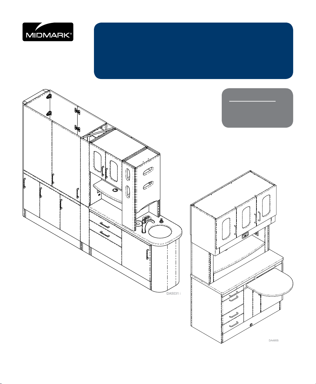
CS
Synthesis® Casework
User’s Information
For Models:
Dental TS Casework
Dental CS Casework
TS
User Guide
003-10110-00 Rev. AA3 (6/20/2019)
TP202 20-42-FO-00014 Rev A1 C2169
Style P
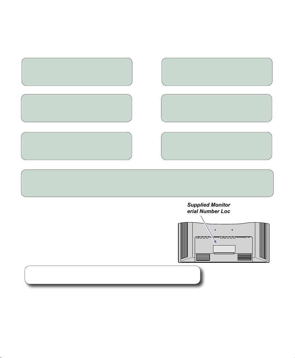
Owner’s Product Information
(The information below is required when calling for service)
Model Number:
Date of Purchase:
Name of Dealer:
Midmark Authorized Service Company:
Model, Serial, or Sales Order Number Location.
In most cases, the Model, Serial, or Sales Order
Number(s) can be located by opening the door(s)
of the Base Cabinet and checking on the inside
walls of the cabinet.
Serial Number:
Name of Owner / Facility:
Dealer Phone Number:
Midmark Supplied Monitor
Model / Serial Number Location
Calling for Service
Note
Model / Serial number information is required when calling for service.
If service is required, contact your Midmark dealer.
To contact Midmark directly:
1-800-Midmark (1-800-643-6275)
8:00 am until 5:00 pm, Monday - Friday (EST)
www.midmark.com
003-10110-00 © Midmark Corporation 2017 TP202 20-42-FO-00014 Rev A1 C2169
2
DA2214i

Table of Contents
Important Information
Owner’s Product Information ....................................................................................................2
Safety Symbols ........................................................................................................................4
Transportation / Storage Conditions ......................................................................................... 5
Safety Instructions ....................................................................................................................5
Electrical Interference ..............................................................................................................5
Operating Enviroment ..............................................................................................................5
Disposal of Equipment .............................................................................................................5
Intendinded Use
Intended Use, Central Station (CS) ......................................................................................6, 7
Intended Use, Treatment Station (TS) ..................................................................................8, 9
Operation
Removal / Installation of 2” Drawer ........................................................................................10
Removal / Installation of Drawers ..........................................................................................11
Installing Doors, Handles and Shelves ..................................................................................12
Door Adjustments ...................................................................................................................13
Door Adjustments continued ..................................................................................................14
Controls ..................................................................................................................................15
Intended Use, Task Light with Clock / Timer ..........................................................................15
Backup Power Mode ..............................................................................................................15
Setting Time of Day ................................................................................................................16
Timer Count-Down Operation ................................................................................................17
Timer Count-Up Operation .....................................................................................................18
Programming Preset Timer(s) for Time Setting ......................................................................18
Preset Timer(s) Count-Down Operation .................................................................................19
Track Monitor Arm
Intended Use ..........................................................................................................................20
Monitor Arm Adjustment ...................................................................................................21, 22
Cleaning & Maintenance ..................................................................................................23, 24
Warranty Information
Limited Warranty ....................................................................................................................25
003-10110-00 © Midmark Corporation 2017 TP202 20-42-FO-00014 Rev A1 C2169
3
Important Information
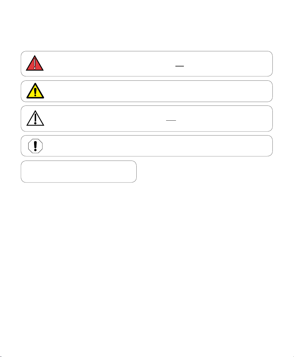
Safety Symbols
DANGER
Indicates an imminently hazardous situation which will result in serious or fatal injury.
This symbol is used only in the most extreme conditions.
WARNING
Indicates a potentially hazardous situation which could result in serious injury.
Caution
Indicates a potentially hazardous situation which may result in minor or moderate injury.
It may also be used to alert against unsafe practices
Equipment Alert
Indicates a potentially hazardous situation which could result in equipment damage.
Note
Amplifies a procedure, practice, or condition.
PREFABRICATED MEDICAL HEADWALLS AND MEDICAL SUPPLY UNITS
CS series, TS series
Have been investigated by UL in accordance with the Standard(s) indicated on this Certicate.
UL60601-1 and CAN/CSA C22.2, No. 601.1-M90, Medical Electrical Equipment, Part 1: General Requirements Safety
NFPA 70, National Electrical Code (NEC) C22.2 No. 0-M90, General Requirements - Canadian Electrical Code, Part II
UL 732, Test for Surface Burning Characteristics of Building Materials.
Product Registration
To register your product, go to www.midmark.com
003-10110-00 © Midmark Corporation 2017 TP202 20-42-FO-00014 Rev A1 C2169
4

Transportation / Storage Conditions
Ambient Temperature Range: ................................................................. -22°F to +140°F (-30°C to +60°C)
Relative Humidity.........................................................................................10% to 90% (non-condensing)
Atmospheric Pressure ........................................................................ 7.2Psi to15.3Psi (50kPa to 106kPa)
Safety Instructions
The primary concern of Midmark is that this equipment is operated and maintained with the safety of the
patient and sta in mind. To assure safer and more reliable operation
• Read and understand this manual before attempting to operate the unit.
• Assure that appropriate personnel are informed on the contents of this manual; this is the responsibility
of the purchaser.
• Assure that this manual is located near the unit.
Electromagnetic Interference
The Midmark Casework is designed and built to minimize electromagnetic interference with other devices
However, if interference is noticed between another device and this product:
• Remove interfering device from room
• Plug Casework into a dedicated circuit
• Increase separation between Casework and interfering device
• Contact Midmark if interference persists
Operating Environment
Ambient Temperature Range; .... +68°F to 104°F (+20°C to 40°C)
Relative Humidity: ................ less than 80%(non-condensing)
• Approved for indoor use only.
Disposal of Equipment
At the end of product life, the casework, accessories, and other consumable goods may become
contaminated from normal use. Consult local codes and ordinances for proper disposal of equipment,
and other consumable goods.
WARNING
Equipment is not suitable for use in the presence
of a flammable anesthetic mixture with oxygen, air,
or nitrous oxide.
Clarification: Equipment is suitable for use in the presence
of oxygen, air, or nitrous oxide.
003-10110-00 © Midmark Corporation 2017 TP202 20-42-FO-00014 Rev A1 C2169
5

Central Station
003-10110-00 © Midmark Corporation 2017 TP202 20-42-FO-00014 Rev A1 C2169
6

Intended Use - CS
The Central Station (CS) provides exible storage congurations to be used in Dental Oces.
Electrical Rating / Requirements
Note
To ensure unit is properly grounded, it must be connected to a
matching grounded, dedicated, correctly polarized receptacle.
CS 120V 120 VAC, 50/60 HZ, 20 amp.
Facility Branch Circuit Ratings Dedicated branch circuit rated at 120 VAC, 50/60 Hz, 25 amp.
CS Dental Casework Powered Options
Options:
Electrical
Rating
*Total connected load not to exceed CS electrical ratings.
Task Light
120VAC,
60 HZ
0.63 AMP
Cabinet
Mounted Light
115VAC, 50/60 HZ
1.2 AMP
003-10110-00 © Midmark Corporation 2017 TP202 20-42-FO-00014 Rev A1 C2169
7
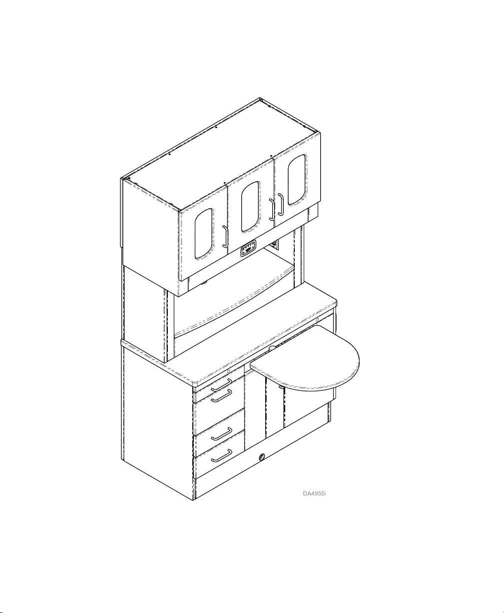
Treatment Station
003-10110-00 © Midmark Corporation 2017 TP202 20-42-FO-00014 Rev A1 C2169
8

Intended Use - TS
The Treatment Station (TS) can be used as the primary Operatory workstation, providing the needed storage and support at the essential Twelve O’clock position.
Electrical Rating / Requirements
Note
To ensure unit is properly grounded, it must be connected to a
matching grounded, dedicated, correctly polarized receptacle.
TS 120V 120 VAC, 50/60 HZ, 20 amp.
Facility Branch Circuit Ratings Dedicated branch circuit rated at 120 VAC, 50/60 Hz, 20 amp.
TS Dental Casework Powered Options
Power Supply
(Heat Syringe)
(Scaler),
(Curing Light),
Electric handpiece
115VAC, 50/60 HZ,
3 Amp
Hand Piece
Illumination
Power Adapter
120V, 60HZ,
0.125 Amp
Options:
Electrical
Rating
Task Light
120VAC,
60 HZ
0.63 AMP
USB Hub
(4port) Power
Adapter
100-240VAC,
50/60HZ,
0.45 AMP
CPU Fan
(USB powered)
5V DC,
0.35-
0.40 A
*Total connected load not to exceed TS electrical ratings.
Accessories: Clock Timer and
Monitor Mount Arm
Clock Timer
Options:
Electrical
Rating
003-10110-00 © Midmark Corporation 2017 TP202 20-42-FO-00014 Rev A1 C2169
Power
Adapter
100-240V
50/60 HZ
0.4 AMP
Midmark Supplied
Power Supply
Ratings
100-240V
50/60 HZ
2 AMP
9

Removal / Installation of 2” Drawers
To easily clean or remove liquids from drawer simply remove drawers by pulling or pushing side levers down
or up on sides of slides to release drawer.
Side
Lever
003-10110-00 © Midmark Corporation 2017 TP202 20-42-FO-00014 Rev A1 C2169
10

Removal / Installation of Drawers
To easily clean or remove liquids from drawer simply remove drawers by pulling on sides of drawer to
release tabs.
003-10110-00 © Midmark Corporation 2017 TP202 20-42-FO-00014 Rev A1 C2169
11

Installing Door, Handles and Shelves
Adhesive
Covers
Installing Handles (If applicable)
Install door handle using hardware supplied.
Shelf
Clip
Installing Shelf Clips & Shelf
Tilt shelf to fit into cabinet as shown. Install
shelf clips and place shelf on top of clips.
Installing Handles (If applicable)
Install drawer handle using hardware supplied. Place
adhesive covers over screw heads.
Installing Doors
Install doors as shown.
003-10110-00 © Midmark Corporation 2017 TP202 20-42-FO-00014 Rev A1 C2169
12

Door Adjustment
Left
Right
Down
Up
Door Adjustment Side to Side
Turn screw located closest to door to increase or
decrease the door overlay side to side (+ or - 2 mm).
003-10110-00 © Midmark Corporation 2017 TP202 20-42-FO-00014 Rev A1 C2169
Door Adjustment Up and Down
Turn cam screw located in center of mounting plate
to adjust door position up or down (+ or - 2 mm).
13

Door Adjustment continued...
In
Out
Door Adjustment Away or Closer
Turn Spiral Tech cam screw located furthest from door
to position the door farther from or closer to cabinet
(+3 mm or -2 mm).
003-10110-00 © Midmark Corporation 2017 TP202 20-42-FO-00014 Rev A1 C2169
14

Controls
Intended Use - Clock / Timer
This product is intended to be used as a timing device to indicate the time of day, and provide a means of
timing various processes used in the medical or dental procedures.
Operation
Backup Power Mode
If power is out for less than 30 seconds:
• Clock automatically restores correct time of day.
• Timer and display operation restored as if no power loss occurred.
• No alarm if timer counts down to zero during power loss.
If power is out for more than 30 seconds:
• Timer memory loses preprogrammed times.
• Preset times return to factory setting:
(Timer 1 = 40 secs. Timer 2 = 3:00 minutes).
• If necessary, Preset times must be reset.
003-10110-00 © Midmark Corporation 2017 TP202 20-42-FO-00014 Rev A1 C2169
15

Clock/Timer Operation
Setting Time of Day
Press and Hold (Two Beeps) for three seconds.
Clock
Current Setting
Press
Hour/Min
Press
Hour/Min
Press
Min/Sec
Press
Min/Sec
Press
Clock
to increment Hour digit to desired time.
to decrement Hour digit to desired time.
to increment Minutes digit to desired time.
to decrement Minutes digit to desired time.
(One Beep) to Save the new time of day setting.
New Time of Day
Note
If the button is not depressed when the timer ends, the Clock / Timer will
begin to count-up. The time that has passed since the end of the
Clock alarm will be displayed.
003-10110-00 © Midmark Corporation 2017 TP202 20-42-FO-00014 Rev A1 C2169
16

Clock/Timer Operation
Timer Count-Down
Press (One Beep)
00:00
Start
Press
Hour/Min
Press
Hour/Min
Press
Min/Sec
Press
Min/Sec
Note
Pressing (One Beep) cancels the count-down program and Time of Day is displayed.
Clock
to increment Minutes digit to desired setting.
to decrement Minutes digit to desired setting.
to increment Seconds digit to desired setting.
to decrement Seconds digit to desired setting.
Current Time of Day
Press (One Beep) to begin timer count-down.
Start
At the end of the count-down the display
shows and the alarm sounds 5 times:
Press
Clock
003-10110-00 © Midmark Corporation 2017 TP202 20-42-FO-00014 Rev A1 C2169
(One Beep) to stop the alarm.
17
00:00

Timer Count-Up
Clock/Timer Operation
Press (One Beep)
Start
Press
Start
(One Beep) to begin timer count-up.
00:00
00:01
Note
Pressing (One Beep) cancels the count-up program and Time of Day
is displayed.
Clock
Programming Preset Timer(s) for Time Setting
Current Time of Day
Press until desired preset to change is reached.
Preset
Current Programmed Preset Time
Press
Hour/Min Min/ Sec
Press
Hour/Min Min/ Sec
Press and Hold
Preset
or to increase desired time.
or to decrease desired time.
for three seconds to save new programmed time.
New Programmed Preset Time
003-10110-00 © Midmark Corporation 2017 TP202 20-42-FO-00014 Rev A1 C2169
18

Clock/Timer Operation
Preset Timer(s) Count-Down
Press until desired preset to change is reached.
Preset
Current Programmed Preset Time
Press
Start
(One Beep) to begin timer count-down.
Note
Pressing (One Beep) cancels the count-down program and Time of Day
is displayed.
Clock
At the end of count-down the display shows
and the alarm sounds 5 times.
Press
Clock
(One Beep) to stop the alarm.
Current Time of Day
00:00
Note
If the button is not depressed when the timer ends, the Clock / Timer will
begin to count-up. The time that has passed since the end of the
Clock alarm will be displayed.
003-10110-00 © Midmark Corporation 2017 TP202 20-42-FO-00014 Rev A1 C2169
19

Track Monitor Arm - (Optional)
The sliding track monitor mount is intended to allow the dental clinician to position the monitor in such a way
that it provides an ecient method of viewing all media (oce schedule, patient charts, digital x-rays, etc.)
from the midmark 12:00 cabinet position while seated in the Doctor’s or Assistant’s stool and while standing
on either left hand or right hand side of the Midmark 12:00 cabinet.
003-10110-00 © Midmark Corporation 2017 TP202 20-42-FO-00014 Rev A1 C2169
20
2967i

Range of Motion and Tension Adjustment
for Track Monitor Arm
To rotate Monitor Arm...
Hold sides of monitor to rotate
from side to side.
Top View
2967i
Monitor
Range of Motion
+ 180°
To position Monitor Arm...
Hold sides of monitor to move
back and forth.
Set Screw
Adjusting tension on Monitor Arm...
Slightly tighten or loosen set screw with
allen wrench.
2968i
003-10110-00 © Midmark Corporation 2017 TP202 20-42-FO-00014 Rev A1 C2169
21

Range of Motion and Tension Adjustment for Monitor
Monitor Height adjustment...
To rotate Monitor...
Hold sides of monitor to rotate
from side to side.
Range of Motion
To Tilt Monitor...
Hold sides of monitor push up or
down to desired angle.
A) Hold bottom of monitor.
B) Push button in on side of monitor mount.
C) Adjust up and down and release button
making sure it pops out.
Max 15° up or
15° down
Tilt adjustment tension...
A) Remove side cover on monitor mount.
B) Slightly tighten or loosen bolt with
allen wrench.
Monitor Mount
Side Cover
Bolt
003-10110-00 © Midmark Corporation 2017 TP202 20-42-FO-00014 Rev A1 C2169
22
2969i

Cleaning / Maintenance (Disinfecting)
Disinfecting Procedures for External Surfaces
Chemical Disinfectant:
Note
Every dental practice setting is dierent and no one disinfectant is the choice for every
facility.
Due to this fact there are several organizations, educated in disinfection procedures, with
web sites that can assist dental personnel in choosing what is best for their practice.
Listed below are several links to some of these sites.
Organization for Safety & Asepsis Procedures
http://www.osap.org
American Dental Association
http://www.ada.org
Dept. of Health & Human Resources
Centers for Disease Control & Prevention (CDC)
http://www.cdc.gov/OralHealth/infectioncontrol/index.htm
When using a disinfectant:
• Carefully read the product label and
directions for use.
• Donotexceedthedilutionrate.
WARNING
If a surface has been contaminated, it will need to be cleaned and disinfected using
the techniques described in this manual and EPA-registered hospital disinfectants.
003-10110-00 © Midmark Corporation 2017 TP202 20-42-FO-00014 Rev A1 C2169
23

Cleaning / Maintenance (Monitor)
Note
The Monitor contains a water sealed, anti-glare, glass front that can be wiped clean with a mild
solution of soap and water or disinfectant.
Refer to Chemical Disinfectant in this manual for direction to specic Associations or Organizations
for recommended disinfectants and procedures.
WARNING
Do not block the vent holes in the monitor case. Do not insert sharp objects or
spill liquid into the LCD monitor through the cabinet slots.
Failure to comply may cause accidental fire, electrical shock, or equipment failure.
Caution
Unplug the monitor power
cable before cleaning.
Monitor
Power
Model Number
Serial Number
003-10110-00 © Midmark Corporation 2017 TP202 20-42-FO-00014 Rev A1 C2169
24
DA2136i

Midmark Dental Casework Limited Warranty
Extension of Warranty
Midmark™ Corporation (“Midmark”) warrants to the original purchaser its Synthesis® Casework,
manufactured by Midmark, to be free from defects in material and workmanship under normal interior use
and service. Midmark’s obligation under this warranty is limited to the repair or replacement, at Midmark’s
option, of the parts or the products the defects of which are reported to Midmark within the applicable
warranty period and which upon examination by Midmark prove to be defective.
Applicable Warranty Period
The applicable warranty period, measured from the date of delivery to the original user, shall be as follows:
(a) Five (5) years for all products and components including door and drawer fronts, casters and slides,
except for the items in (b), (c) and (d)..
(b) Three (3) years for electrical components such as task lights/LED lights, cords, controls and
accessories..
(c) Two (2) years for sliding track monitor mount and components and upholstery.
(d) One (1) year for countertops and resin, including accessories..
Exclusions
Midmark’s warranty does not cover sinks, faucets, and plumbing accessories. Any warranties on these
items are extended directly by the manufacturer of these items to the original purchaser. Information on
these manufacturers’ warranties will be enclosed with the applicable products. Also, Midmark will furnish
copies of any of the warranties extended by any such manufacturers upon request.
This warranty does not cover and Midmark shall not be liable for: (1) repairs and replacements required
because of misuse, abuse, negligence, alteration, accident, freight damage, or tampering; (2) matching of
color, grain, or texture except to commercially acceptable standards; (3) changes in color caused by
natural or articial light; (4) products which are not installed, used, and properly cleaned as required in
Midmark’s written Installation Manual; (5) specially manufactured products; (6) products considered to be
of consumable nature such as light lamps and surge suppression product; (7) accessories or parts not
manufactured by Midmark; (8) charges by anyone (including Midmark’s authorized Midmark Dental Case-
work dealers) for adjustments, repairs, replacement parts, installation, or other work performed upon or in
connection with such products which is not expressly authorized in writing in advance by Midmark.
Exclusive Remedy
Midmark’s only obligation under this warranty is the repair or replacement of defective parts. Midmark shall
not be liable for any direct, special, indirect, incidental, exemplary, or consequential damages or delay.
No Authorization
No person or rm is authorized to create for Midmark any other obligation or liability in connection with the
products.
THIS WARRANTY IS MIDMARK’S ONLY WARRANTY AND IS IN LIEU OF ALL OTHER WARRANTIES,
EXPRESS OR IMPLIED. MIDMARK MAKES NO IMPLIED WARRANTIES OF ANY KIND INCLUDING
ANY WARRANTIES OF MERCHANT-ABILITY OR FITNESS FOR ANY PARTICULAR PURPOSE. THIS
WARRANTY IS LIMITED TO THE REPAIR OR REPLACEMENT OF DEFECTIVE PARTS.
003-10110-00 © Midmark Corporation 2017 TP202 20-42-FO-00014 Rev A1 C2169
25

Notes:
003-10110-00 © Midmark Corporation 2017 TP202 20-42-FO-00014 Rev A1 C2169
26

Notes:
003-10110-00 © Midmark Corporation 2017 TP202 20-42-FO-00014 Rev A1 C2169
27

Midmark Corporation
www.midmark.com
60 Vista Drive
Versailles, OH 45380 USA
1-800-643-6275
1-937-526-3662
TP202 20-42-FO-00014 Rev A1 C2169
 Loading...