

Midmark Progeny Vantage Service Manual
Progeny Vantage Panoramic X-ray System
Product Generation 2.1
Technical Service Manual
00-02-1698
Revision B01

Progey Vantage® Panoramic X-ray System
Technical Service Manual
Contents
2

Progey Vantage® Panoramic X-ray System
Technical Service Manual
Contents
Contents
1 How to Use This Manual ........................................................................................................................ 5
Introduction .......................................................................................................................................... 5
Related Manuals ................................................................................................................................. 6
Warnings and Cautions ....................................................................................................................... 6
Symbols and Conventions ................................................................................................................. 11
Specifications .................................................................................................................................... 13
Obtaining Technical Support ............................................................................................................. 14
2 Theory of Operations ........................................................................................................................... 15
System Overview .............................................................................................................................. 15
About the Components...................................................................................................................... 16
Operational Systems ......................................................................................................................... 23
3 Troubleshooting Resources ................................................................................................................ 27
Obtaining Assistance through Remote Access ................................................................................. 27
Service Kit ......................................................................................................................................... 27
Message Center ................................................................................................................................ 28
Error Logs .......................................................................................................................................... 36
Wiring Diagrams ................................................................................................................................ 37
Printed Circuit Boards ....................................................................................................................... 38
Troubleshooting with Printed Circuit Boards ..................................................................................... 43
Network Communications ................................................................................................................. 56
4 Troubleshooting Procedures .............................................................................................................. 58
Communications Failure ................................................................................................................... 58
Operator Panel Failure ...................................................................................................................... 60
Movement Operations Failure ........................................................................................................... 60
X-ray Output Failure or Is Incorrect ...................................................................................................66
Sensor Failure ................................................................................................................................... 69
Indicators Failure ............................................................................................................................... 70
5 Troubleshooting Image Quality........................................................................................................... 71
Characteristics of a Quality Image .................................................................................................... 71
Typical Problems and Their Causes ................................................................................................. 72
Checking Image Quality .................................................................................................................... 73
6 Overview of Service Tasks .................................................................................................................. 76
Service Screen Overview .................................................................................................................. 76
Opening and Using the Service Screen ............................................................................................ 76
Cycle Test .......................................................................................................................................... 79
7 C-arm ..................................................................................................................................................... 80
C-arm Alignment ................................................................................................................................ 80
8 Overhead Arm ....................................................................................................................................... 81
Y-axis Alignment ................................................................................................................................ 81
3

Progey Vantage® Panoramic X-ray System
Technical Service Manual
Contents
X-axis Alignment ................................................................................................................................ 82
9 Collimator and X-ray Source ............................................................................................................... 83
Collimator Calibration ........................................................................................................................ 83
Beam Alignment ................................................................................................................................ 84
10 Telescoping Column ............................................................................................................................ 85
Column Optical Limit Switch Function ............................................................................................... 85
11 Lasers ....................................................................................................................................................86
Align Lasers ....................................................................................................................................... 86
12 X-ray Sensors ....................................................................................................................................... 88
Align the X-ray Sensor ...................................................................................................................... 88
13 Patient Positioning Wands .................................................................................................................. 91
Set Wand Open Position ................................................................................................................... 91
14 Patient Positioning Table .....................................................................................................................92
Patient Positioning Table Alignment .................................................................................................. 92
15 Operational Readiness ........................................................................................................................93
System Function Checklist ................................................................................................................ 93
Appendix A. Operator Panel Non-Service Menus ..............................................................................95
Acquisition Setup Screen .................................................................................................................. 95
Options Screen .................................................................................................................................. 97
Recall Last Image .............................................................................................................................. 99
System Center ................................................................................................................................. 100
X-ray Voltage and Current Properties Screen .................................................................................. 101
Profile Properties Screen ................................................................................................................. 101
4

1 How to Use This Manual
For
Go
How the
system works
Chapter
Chapter
Error messages
Chapter
Boards and test points
Chapter
Chapter
IP addresses
Chapter
Troubleshooting
Chapter
Improving image quality
Chapter
Serv
Chapter
Maintenance procedures
Chapter
Readiness checklists
Chapter
Operator panel screens
Appendix A
In this Chapter
• Introduction
•
Related Manuals
•
Warnings and Cautions
•
Symbols and Conventions
Specifications
•
•
Obtaining Technical Support
Introduction
The Technical Service Manual is used for regular maintenance and service of the Progey Vantage®
panoramic X-ray system. The work should be performed by a technician familiar with this product.
Quick References
information on…
Progeny Vantage®
ice screen
to …
2, System Overview on page 15
2, About the Components on page 16
3, Message Center on page 28
3, Printed Circuit Boards on page 38
3, Troubleshooting with Printed Circuit Boards on page 43
3, Network Communications on page 56
4, Troubleshooting Procedures on page 58
5, Typical Problems and Their Causes on page 72
6, Service Screen Overview on page 76
7 through Chapter 14 starting from page 80
15, System Function Checklist on page 93
, Operator Panel on page 95

Progey Vantage® Panoramic X-ray System
Technical Service Manual
How to Use This Manual
Title Description
Progey Vantage
panoramic X
Installation Guide
The
explains
client computers
Vantage
Progey Vantage
panoramic X
User Guide
The
system and provides instructions o
patient, acquiring images, and resolv
WARNING
Ionizing Radiation
Related Manuals
The following manuals will be helpful when servicing the Progey Vantage® panoramic X-ray system.
Related Manuals
®
-ray system,
®
-ray system,
Installation Guide identifies requirements for installation;
®
device, how to install cables, and how to start up.
User Guide explains the components of the Progey Vantage®
setup; and describes how to install the Progey
n getting started, positioning a
ing image problems.
Warnings and Cautions
This X-ray unit may be dangerous to patient and operator unless
safe exposure factors, operating instructions, and maintenance
schedules are observed. Removing build-in protection devices
increases the risk of undesired X-ray irradiation.
Trained and authorized personnel only shall operate unit.
Read and understand all enclosed documents before installation,
use, maintenance, or repair.
RADIATION SAFETY INSTRUCTIONS
1. Operate by observing all laws and regulations concerning radiation protection.
2. Remain at a safe distance from the X-ray beam at all times for operator protection.
3. Use all radiation safety features on the equipment.
4. Do not operate without X-ray sensor and X-ray beam-limiting devices (collimator), primary and
secondary when equipped.
5. Do not open the X-ray tubehead. There are no serviceable parts inside.
6. Use all radiation protection devices, accessories, and procedures available to protect the
patient, operator, and the service personnel from X-ray radiation.
6
Progey Vantage® Panoramic X-ray System
Technical Service Manual
How to Use This Manual
WARNING
Dangerous Voltage Inside
Contact may cause electric shock or burn.
Under the covers, there are exposed parts carrying currents with
the line voltage, with 48 V, and with 24 V or lower voltages.
Do not allow water or any other liquid to leak inside the equipment
to protect against short-circuit and corrosion. This is an ordinary
medical device without protection against ingress of liquids.
Trained and authorized personnel only should install equipment and
remove covers.
Connect to supply mains with protective earth (ground).
Disconnect equipment from the electrical supply mains before
cleaning, disinfecting, maintenance, or servicing. Wait 30 s before
touching any internal parts.
Read and understand all enclosed documents before installation,
use, maintenance, or repair.
ELECTRICAL SAFETY INSTRUCTIONS
7
Progey Vantage® Panoramic X-ray System
Technical Service Manual
How to Use This Manual
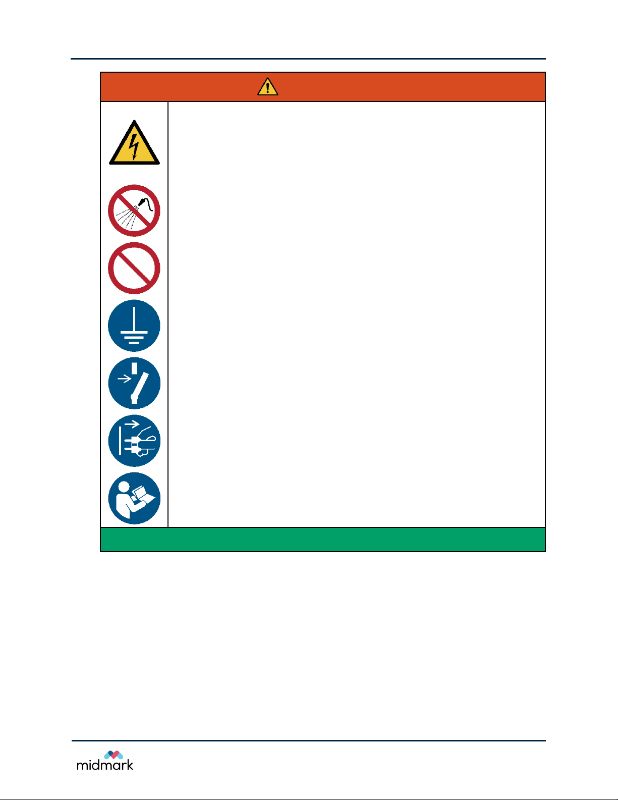
CAUTION
Pinch Points Exists Inside
1. Do not change X-ray sensor when any part of the equipment or the operator touches the
patient.
1. Do not execute any maintenance or repair services that require removing of protective
covers when the patient is present.
2. Do not open the X-ray sensor or the X-ray tubehead. There are no serviceable parts
inside.
3. Do not touch the internal metal parts when energized.
4. Do not short two test points together or short a test point to any other part.
5. Install and use in areas that comply with all applicable laws and recommendations
concerning electrical safety in rooms used for medical purposes, e.g., U.S. National
Electrical code, local regulations, or IEC standards concerning provisions of an additional
protective earth (ground) terminal for power supply connection. Consult with a licensed
professional if needed.
This equipment contains closing motion of mechanical parts that
create pinch points when the covers are removed.
Disconnect equipment from the electrical supply mains before
cleaning, disinfecting, maintenance, or servicing.
Read and understand all enclosed documents before installation,
maintenance, or repair.
OPERATION SAFETY INSTRUCTIONS
1. Replace all enclosures before operating the equipment.
2. Keep all parts of the body away from the equipment when initiating motion.
8
Progey Vantage® Panoramic X-ray System
Technical Service Manual
How to Use This Manual
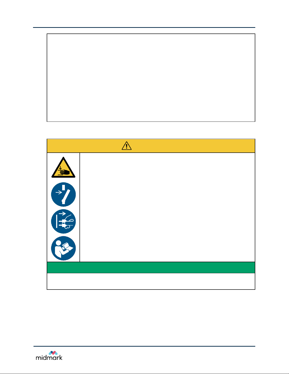
CAUTION
Laser Radiation
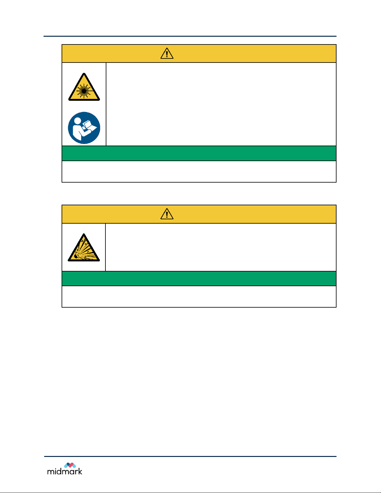
CAUTION
Risk of Explosion
This equipment contains CLASS 2 LASER PRODUCT, 650 nm,
3 mW with a 40° fan line beam and non-removable optical system.
Laser on time does not exceed 100 s per activation.
Read and understand all enclosed documents before installation,
use, maintenance, or repair.
LASER RADIATION SAFETY INSTRUCTIONS
3. Do not stare into the beam.
4. Do not place eyes closer than 100 mm.
Do not use in in the presence of flammable or potentially explosive
gases or vapors, which could ignite, causing personal injury and/or
damage to the equipment.
EXPLOSION SAFETY INSTRUCTIONS
1. Allow vapor to disperse before using the equipment after cleaning or disinfecting with
chemicals that create flammable or potentially explosive vapors.
9

Progey Vantage® Panoramic X-ray System
Technical Service Manual
How to Use This Manual
CAUTION
Electrostatic Sensitive Devices Inside
1.
⊕
⊕
This equipment contains electrical circuit that has not been tested
for immunity to electrostatic discharge and may be damaged when
improperly handled.
Do not touch or disconnect the electrical components and assemblies, i.e. boards, cables,
connectors, etc., unless this manual contains instructions to do so.
2. Do not remove electrical components and assemblies from the metal carrier or enclosure
unless instructed by this manual or by technical support.
3. Do not touch the conductive parts of the test leads when a measurement is taken.
4. Do not short two test points together or short a test point to any other part.
5. Keep the replacement components inside of the protective packaging until ready for
installation.
6. Place a removed component board-side-up on an antistatic surface or in a static-shielding
container.
ESD SAFETY INSTRUCTIONS
OTHER SAFETY INSTRUCTIONS
Trained and authorized personnel only should service equipment or remove covers.
Use the tools and the equipment specified in this manual for the performed task.
7. When finished servicing equipment, perform functional check and maintenance
procedures listed in this document and in the User Guide.
8. Use this document as a guidance. Contact technical support when help is needed
10
Progey Vantage® Panoramic X-ray System
Technical Service Manual
How to Use This Manual
Symbol
Explanation
General warning sign
Advice
s with
the
if the hazardous situation is not explained next to the sign.
Caution
Advice
Attention
Conseils pour la présence de rayons X liées situation dangereuse
Warning
Advice
Warning, Electricity
Advice
Warning, Crushing of hands
Advice
Caution
Advice
sources
Warning
Advice
used
Caution, Electrostatic sensitive devices
Advice
devices.
General prohibition sign
Advice
an action specified by the supplementary sign.
Do not spray with water
Advice
spraying with water on
Symbols and Conventions
written instructions in the User Guide, Installation Manual, and Service Manual
for the presence of a hazardous situation. The operator must consult
X-ray
for the presence of X-ray related hazardous situation.
: Rayons-X
.
, Ionizing Radiation (X-ray)
for the presence of X-ray related hazardous situation.
for the presence of dangerous electricity.
for the presence of a dangerous closing motion of mechanical parts.
, Laser beam
for the presence of a dangerous laser beam. This device contains laser
that are:
, Explosive material
for the ability of this equipment to cause explosion when this equipment is
near or when handling explosive materials.
that the package or this equipment contains electrostatic-sensitive
for presence of a hazardous situation that will be prevented by not doing
for presence of a hazardous situation that will be prevented by not
this equipment.
Class 2 Laser Product
650 nm, 3 mW
11

Progey Vantage® Panoramic X-ray System
Technical Service Manual
How to Use This Manual
Symbol
Explanation
Refer to instructio
Advice that the operator must r
as the
Connect an earth terminal to the ground
Advice
conductor of power
Disconnect before carrying out maintenance or repair
Advice
disconnected from all sources of power before carrying out maintenance or repair.
Disconnect mains plug from electrical outlet
Adv
outlet for the purposes of maintenance of electrical equipment, in the case of
malfunction or when left unattended.
Type B applied part (IEC 60601
T
ap
Connection point for the line conductor
Shows the connection point for the
mains
Connection point for the neutral conductor
Shows the connection point for the
mains
Protective Earth (Ground)
Shows the connection point for the protective earth (ground) conductor.
Indicate connection to the power
X
Indicates the emission of X
Separate collection for electrical and electronic equipment according
Directive
Advice
2002/96/EC (WEEE) and
therefore must be disposed as electrical or electronic equipment in E.U.
n manual/booklet
ead and understand all enclosed documents such
User Guide, Installation Manual, and Service Manual.
that this equipment must be connected to a protective earth (ground)
supply mains.
that the equipment, which is not connected to mains by a plug, has to be
ice that the mains plug of the equipment must be disconnected from electrical
-1)
his device provides protection against electric shock as required for Type B
plied parts per IEC 60601-1.
ungrounded conductor of the power supply
(a.k.a. line or hot wire).
grounded conductor of the power supply
(a.k.a. neutral wire).
Terminal
mains:
• Power OFF (circle)
• Power ON (line)
-ray source assembly, emitting
-radiation.
2002/96/EC (WEEE)
that this Progeny Vantage® is subject to Directive
12

Progey Vantage® Panoramic X-ray System
Technical Service Manual
How to Use This Manual
Parameter
Specification
X
Constant potential
and current
X
Canon (
Focal spot size
0.5
Total Filtration
Anode Voltage
(internal control)
50
Regulated to ±
Anode Current
4
Regulated to ±
anode power of 1140
Exposure
Panoramic:
Cephalometric:
Precision
Cooldown Time
Automatically controlled based
SID
Panoramic:
Cephalometric:
Magnification
Panoramic:
Cephalometric:
Image pixel size
96
CCD active area
Panoramic:
Cephalometric:
Image field
Panoramic:
Cephalometric:
Pixels
Panoramic:
Cephalometric:
Specifications
-ray source
-ray Tube
Time
(DC), with microprocessor controlled time, voltage,
.
Toshiba) D-054SB, rated max 1750 W
mm2 (IEC 60336:2005)
min 3.2 mm Al
kV to 84 kV
10% of the indicated value.
mA to 14 mA
20% of the indicated value and limited by the total
W.
2.5 s to 16 s
9 s to 15.6 s
: 50 ms plus ± 5% of the indicated value.
per exposure
500 mm (approx. 20 in.)
left, 1645 mm (approx. 64.75 in.)
right, 1670 mm (approx. 65.75 in.)
1.2 ± 0.05 in horizontal and vertical direction
1.1 ± 0.05 in horizontal and vertical direction
μm × 96 μm (after 2 × 2 binning)
6 mm × 147 mm (approx. 0.24 in. × 5.8 in.)
6 mm × 221 mm (approx. 0.24 in. × 8.7 in.)
14 cm × 30 cm (approx. 5.8 in. × 12 in.)
21 cm × 30 cm (approx. 8.2 in. × 12 in.)
1509 lines x 3180 columns, 16-bits per pixel
2288 lines x 3180 columns, 16-bits per pixel
on the X-ray tube heat load.
13

Progey Vantage® Panoramic X-ray System
Technical Service Manual
How to Use This Manual
Parameter
Specification
Image Transfer Time
Panoramic:
Cephalometric:
Image data size
Panoramic:
Cephalometric
Attenuation Equivalent
of Image Receptor
max 0.4
Electrical Safety
Classification
Class I, Type B
Rated
max 20
Duty Cycle
Approx.
Heat Dissipation into
Surrounding Air
max 320
Operating Temperature
+10
Storage Temperature
-
Maximum Altitude
3000
Line Voltage
max 30 s
max 45 s
average 11.8 MB
: average 17.4 MB
mm Al
110 V – 240 V, 50 Hz or 60 Hz
A (long term 1 A) measured at 110 V
1:30
J (approx. 0.3 BTU)
°C to +35 °C (+50 °F to +95 °F)
35 °C to +66 °C (-31 °F to +150 °F)
m (approx. 9842 ft.)
Obtaining Technical Support
For technical support, contact:
MIDMARK CORPORATION
1001 Asbury Drive
Buffalo Grove, Illinois 60089 U.S.A.
Phone: 800-MIDMARK (1-800-643-6275)
+1 847-415-9800, ext. 108126
Fax: 847-415-9801
imagingtechsupport@midmark.com
Hours: 8:00 a.m. – 5:00 p.m. Central Time
14

Progey Vantage® Panoramic X-ray System
Technical Service Manual
Theory of Operations
2 Theory of Operations
In this Chapter
• System Overview
•
About the Components
•
Operational Systems
System Overview
Panoramic radiography is a branch of tomography, particularly a branch of rotational tomography.
Images of internal structures of the jaw are created by moving the source and receptor in such a way
as to cause the foreground and background structures to blur, leaving a defined focal trough.
Cephalometric radiography is craniofacial radiography of the bony parts and soft tissue of the head.
It uses parallel X-ray technique to preserve the distance and angle relationship between the anatomic
landmarks.
System Description
The Progeny Vantage® panoramic X-ray system is a computer-controlled multi-axis dental panoramic
and cephalometric radiographic device incorporating:
• X-ray source
• Digital X-ray receptor
• Distributed processing
• WVGA LCD touch screen based operator panel
®
The Progeny Vantage
motorized, 3-speed, telescoping column. Multiple lasers are used to locate the patient and configure
the device to the patient’s morphology.
The outer portion of the column, the fixed column, is mounted to the wall and/or floor. It supports the
inner, moving, or telescoping portion of the column. This inner, telescoping column supports both the
patient positioning table and the overhead arm. The overhead arm supports the C-arm, which in turn
supports the X-ray source, or tubehead, and the panoramic X-ray receptor, or panoramic sensor. The
cephalometric attachment is an accessory that is installed to the highest point of the column. It
contains a cephalometric support arm and a cephalometric scanning mechanism. The scanning
mechanism supports the cephalometric sensor and the cephalometric scanning mechanism.
panoramic X-ray device is adjustable to the patient’s height with the
Powering the panoramic X-ray system
The Progeny Vantage® system employs a universal power supply with automatic input voltage
selection and is suitable for most dental offices worldwide. The Progeny Vantage
connected to power supply mains with voltage in the range of 110 V to 240 V and frequency 50 Hz or
60 Hz. The device should be connected also to protective earth (ground) through dedicated wire
incorporated in the power cable or provided separately.
®
device should be
Network Communications
The Progeny Vantage® device employs a fixed, dedicated network between the components inside
of the machine. The Progeny Vantage
®
also uses connection to an external Ethernet based Local
15

Progey Vantage® Panoramic X-ray System
Technical Service Manual
Theory of Operations
Area Network (LAN) that allows images to be transferred from the device to any client computer
connected to that network and running the client software. At least one client computer should be
designated to receive the acquired radiographic image at any given time.
Distributed Processing
The Progeny Vantage® is a multi-processor system. Each system monitors itself and reports errors
to the Operator Panel.
The separate processing systems are:
• Real Time Controller (RTC, or system controller) together with the combined X-ray power and
logic boards, and all motor controllers
• Image sensors
• Operator panel
Inter-module communications utilize Ethernet based network, with power over Ethernet (PoE) switch
being located below the patient positioning table.
Movement profiles and the X-ray technique factors are stored in the Real Time Controller and initiated
by communications from the Operator Panel and by the exposure switch. The RTC controls the
motion produced by the individual motors via commands send thru a dedicated serial link. The RTC
also controls the X-ray generation by commands send to the power and logic boards via a second
serial interface.
Software Architecture
The three separate processing systems run a software to control all aspects of device operation. The
operator panel keeps track of overall system operation, communicating with all subsidiary processors.
The remaining processing systems (RTC and X-ray sensors) all report status to the operator panel,
where the appropriate operations are initiated. Movement and X-ray control are handled by the RTC,
under the parameters communicated to it by the operator panel. The sensor performs all initial
collection and processing of the image before delivering it to the operator panel, wherein secondary
image processing is applied. All system user settings are maintained on the operator panel.
Mechanical and X-ray calibration information are maintained on the RTC and X-ray controller
respectively. The sensor calibration information is maintained on the operator panel and on the
sensor, depending on the level of the calibration information (high vs. low). The processing systems
move together through the various states used to produce the device functions.
About the Components
The Progeny Vantage® panoramic X-ray system includes the following components.
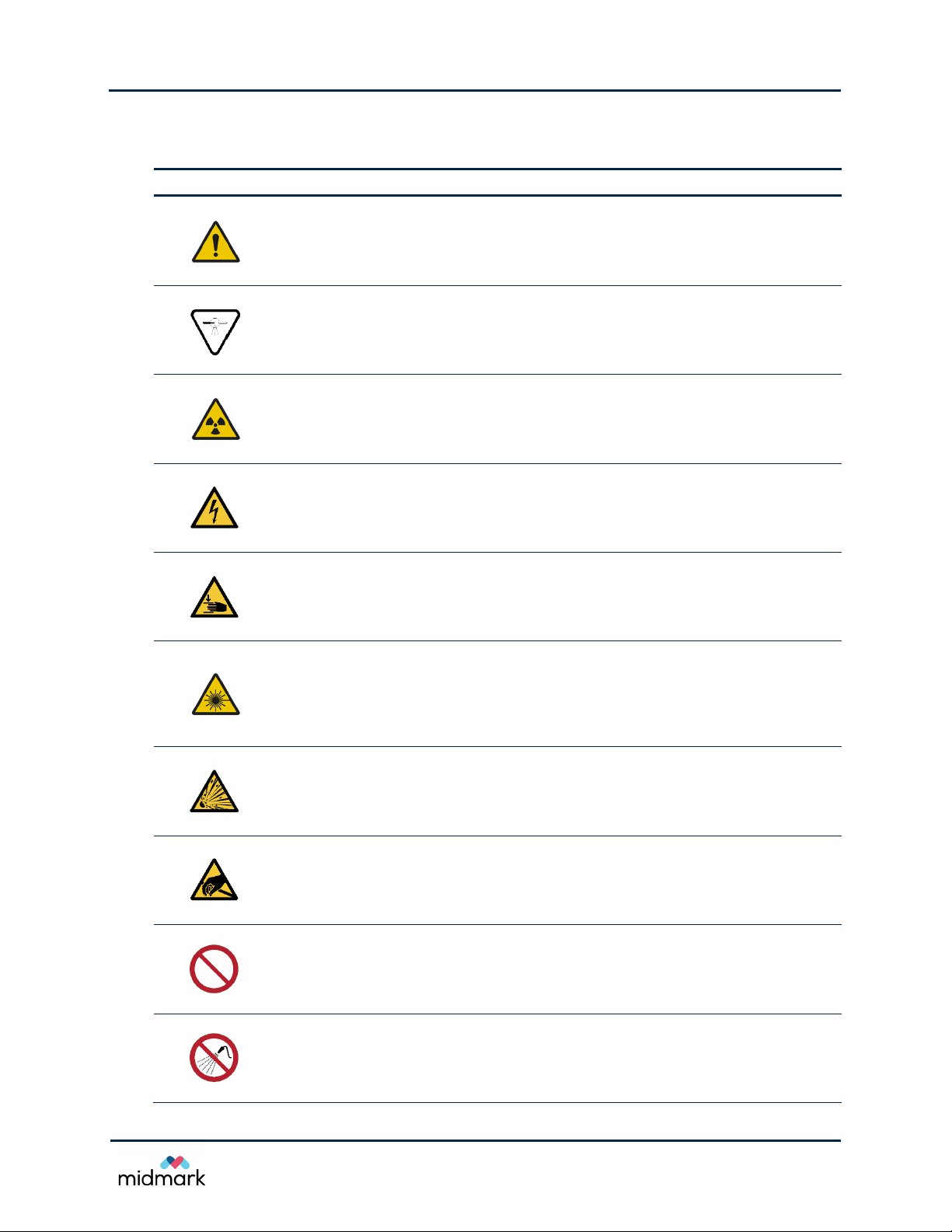
Vertical Column
The vertical column has two main parts: the fixed section and the moving, or telescoping, section.
The fixed section contains the actuator to control up and down movement of the panoramic X-ray
device. The telescoping section contains the positioning lasers. Optical sensors in the telescoping
section define the maximum and minimum extension of the column.
16
Progey Vantage® Panoramic X-ray System
Technical Service Manual
Theory of Operations
Telescoping Section
Fixed
Patient Table
The column is comprised of two extrusions, connected by bearings and a linear actuator. The
bearings are adjustable to align the extrusions to each other, and to minimize slop. The linear actuator
is a gear driven screw with integral brake. The column, actuated by a push button operator panel
located on the side of the patient positioning table, moves at three progressively faster speeds, with
a smooth transition between speeds.
Vertical column
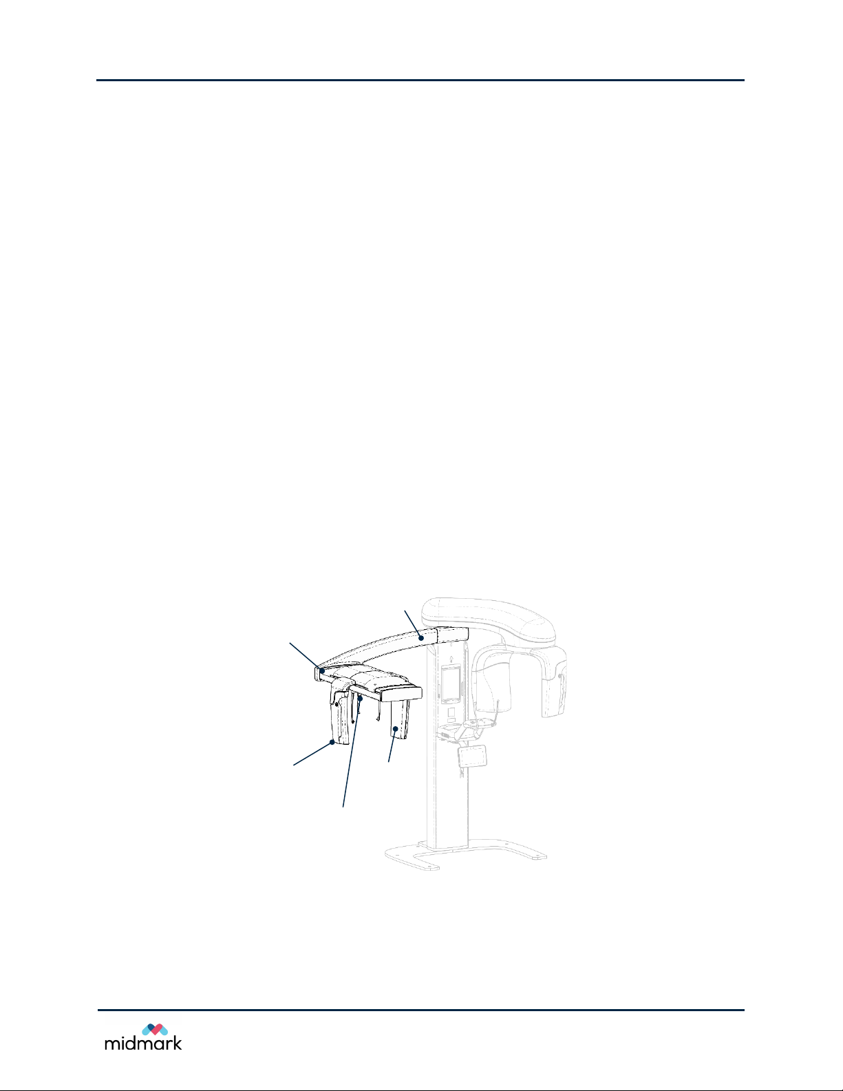
Patient Positioning Table
The patient positioning table guides and supports the patient during acquisition of panoramic X-ray
images by means of the chin rest, bite guide, and positioning wands.
Correct and repeatable patient positioning is essential to producing a clinical-quality image. Patient
positioning is accomplished by the telescoping column, the temple wands, and the reference lasers.
All of these subsystems are actuated by a push-button panel located on the left and the right sides of
the patient positioning table.
The temple wands are located on either side of the chinrest/bite piece assembly. The wands use a
spring to close against the patient’s head, and a motor to open. The maximum opening is controlled
by an optical sensor mounted inside the positioning platform. At any point, the wands can be manually
opened further against the spring.
Patient positioning table
17
Progey Vantage® Panoramic X-ray System
Technical Service Manual
Theory of Operations
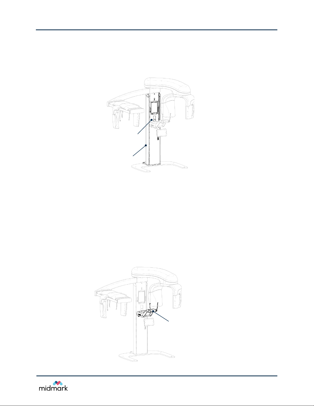
Operator Panel
Operator Panel
The operator panel, mounted under the patient positioning table, acts as the user interface for the
device. It is connected to and powered from the column computer. The operator panel and the column
computer, together, provide top-level control on the Progeny Vantage
commands given via touch screen interface in the operator panel.
Operator panel
®
device based on user
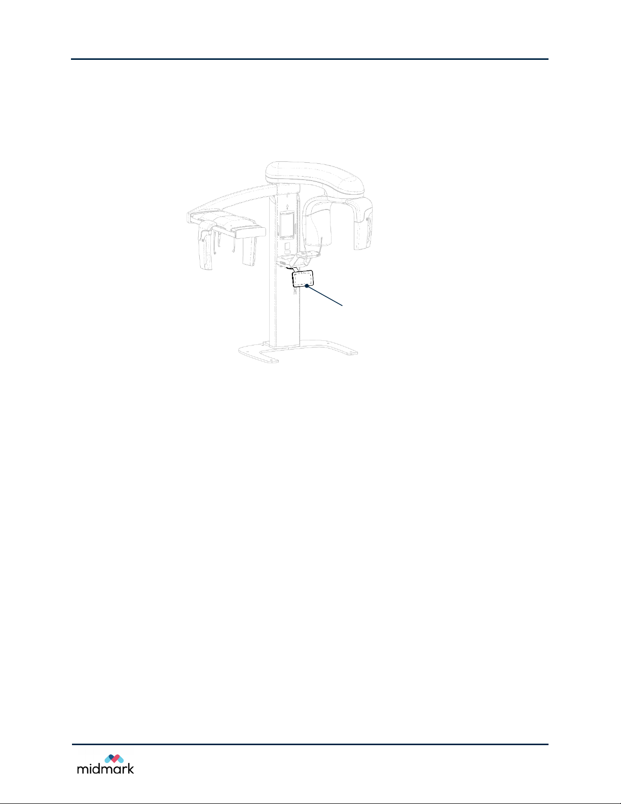
Column Computer
The column computer, mounted on the lower half of the telescoping section of the column, acts as
interface controller to the machine and provides the basic image processing. It has two network
interfaces, one connected to the in-machine network, and the other connected to the office LAN. The
column computer is powered through the 48 V power supply embedded in the column carrier board
located below the patient positioning table.
The column computer is a PC with x86 compatible processor and Windows operating system.
®
Progeny Vantage
software comes installed on the column computer, as do the sensor calibration
files. The software on the column computer provides top-level control on the Progeny Vantage
based on the touch screen commands given by the operator panel. The software also transfers the
image to the Client computer for further processing and storage.
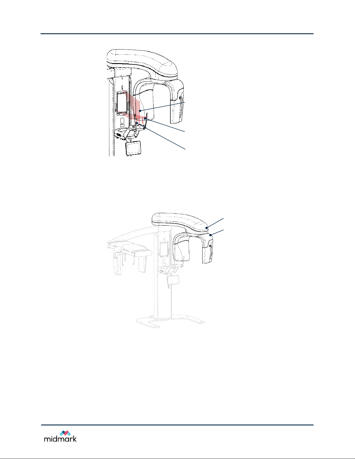
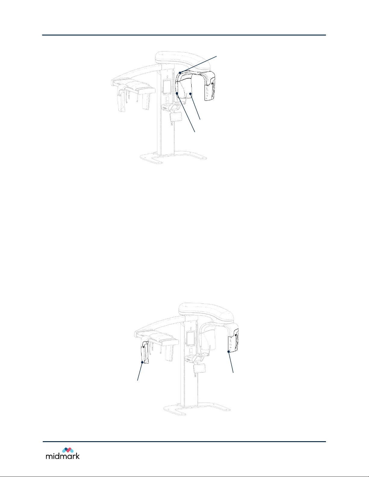
Lasers
There are four reference lasers for locating the patient’s head relative to the device: the Median
(midsagittal) plane, the Frankfort plane, and two Cuspid plane lasers.
The Median (midsagittal) plane provides the vertical center plane reference. It is a fixed laser and is
located on the telescoping section of the column behind the upper cover.
The Frankfort plane provides a horizontal planar reference, and is adjustable vertically to correspond
to the patient’s physiognomy. It is mounted to the inside of the upper column cover, and is mountable
to either the left or the right side of the column upper cover.
The Cuspid lasers are mounted within the patient positioning table and are directed by mirrors up to
the patient’s mouth. The Cuspid lasers are carried on a transit that moves fore and aft. The transit
movement is reported to the real-time controller (RTC) by a slide potentiometer. To define the zero
position for the Cuspid lasers, a hole in the transit is aligned with a similar hole in the patient table
using a precision pin.
®
device
18
Progey Vantage® Panoramic X-ray System
Technical Service Manual
Theory of Operations
Median (midsagittal) plane
Frankfort plane
Cuspid plane
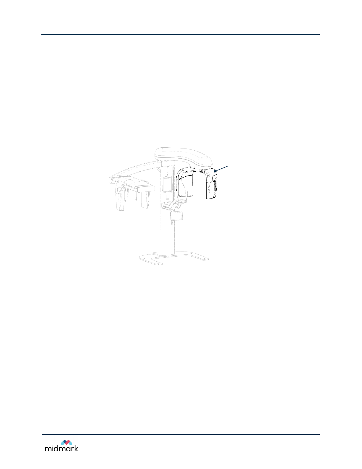
Overhead Arm
C-arm
Lasers
Overhead Assembly
The overhead assembly consists of an overhead (swing) arm and C-arm. The overhead arm supports
the C-arm, which rotates. The C-arm includes the tubehead and the removable sensor. The tubehead
produces the X-ray beam, and the sensor is a digital image receptor.
Overhead assembly
Overhead Arm – Y-axis
For the lateral Y-axis motion, the overhead arm pivots about bearings located in the mounting casting
fastened at the top of the column. Its motion is produced by a ball screw drive with one end connected
to the mounting casting and other end to the overhead arm itself. The stepper motor is near the
column. Both mechanical connections of the drive assembly are through ball bearing assemblies.
An optical sensor on the mounting casting engages a flag on the overhead arm to define a home
reference for the system. Motion is monitored by a potentiometer connected to the ball bearings at
the column end of the drive assembly. To define the zero position for the system, a hole in the swing
arm is aligned with a similar hole in the mounting casting using a precision pin.
19
Progey Vantage® Panoramic X-ray System
Technical Service Manual
Theory of Operations
C-arm
Overhead Arm – X-axis
For the in-and-out X-axis motion, the translation drive of the overhead arm (X-axis) is comprised of a
plate mounted on linear bearings attached to the overhead arm casting. The plate is moved by a
backlashless screw drive with a stepper motor on the fixed end. Position feedback is via a linear
potentiometer with an optical sensor and flag for home reference. A hole in the plate aligns with a
hole in the overhead arm casting using a precision pin to define a system zero position.
C-arm
The C-arm is suspended on a pair of bearings mounted to the underside of the X-axis translation
plate. The C-arm casting incorporates an internal tooth ring gear that meshes with a pinion gear on a
stepper motor mounted on the X-axis translation plate. The motor is spring loaded to maintain positive
mesh and minimize slop.
C-arm
X-ray Source
The X-ray tubehead contains a high-frequency X-ray source that uses a stationary anode X-ray tube
(See Appendix in Progeny Vantage
that is comprised of a power board and a logic board controls and monitors the operation of the X-ray
tubehead. The operation of this circuit is governed by the RTC and is locally controlled by
microprocessor on the logic board. Power for the X-ray source is derived directly from the power
supply mains.
There are no serviceable parts inside of the X-ray tubehead and it must not be opened in the field.
Opening the X-ray tubehead will compromise the high-voltage and X-ray protections embedded
inside of the device and may endanger patient and operator.
The primary collimator is mounted on the output port of the X-ray tubehead. The collimator is a 2-axis
motorized automatic beam-limiting device, whose operation is governed by the RTC and locally
controlled by a motor controller. The two axes are controlled by a single motor controller in sequential
manner. A relay mounted the collimator (motor controller) carrier board directs the motor drive current
as appropriate for the controlled collimator axis.
®
User Guide for X-ray tube information). The X-ray control unit
20
Progey Vantage® Panoramic X-ray System
Technical Service Manual
Theory of Operations
X-ray Control Unit
X-ray Tubehead
Primary Collimator
Cephalometric Sensor
Panoramic Sensor
X-ray source
X-ray Sensors
The image sensor detects X-rays and manipulates the detection to produce an image. It contains a
very large X-ray camera that converts the X-ray to electrical signals, precise circuitry that processes
these signals, frame memory that stores the image between the imaging sessions, and
microprocessor that controls the sensor operation and communicates with the column computer via
an Ethernet connection. The device is powered through the Ethernet connection from the PoE switch
located below the patient table.
The X-ray sensor circuitry is sensitive to impact and the device must be handled with care. There are
no serviceable parts inside of the X-ray sensor and it must not be opened in the field. Opening the
sensor will compromise the X-ray performance of the device and may endanger the patient.
®
The Progeny Vantage
sensor. The difference between the two types is the size of the X-ray active area. The cephalometric
sensor has 50% larger active area than panoramic sensor and therefore the cephalometric sensor
may be used as a panoramic sensor, but the panoramic sensor cannot be used as a cephalometric
sensor.
supports two types of X-ray sensors – panoramic sensor and cephalometric
X-ray sensors
21
Progey Vantage® Panoramic X-ray System
Technical Service Manual
Theory of Operations
Cephalometric
Sensor
Secondary
Collimator
Cephalostat
Support Arm
Scanning
Mechanism
The X-ray sensor implementation automatically converts the cephalometric sensor to panoramic
sensor based on the position ID reported from the floating connector board embedded in the sensor
mount on the C-arm or on the cephalometric transit. In addition, the sensor mount on the
cephalometric transit and the cephalometric sensor contain a mechanical key that do not allow a
panoramic sensor to be attached to the cephalometric accessory. This mechanical key consists of a
pin attached to the sensor mount on the cephalometric transit and a hole embedded in the
cephalometric sensor.
Cephalometric Attachment
The Cephalometric Extension consists of the support arm, the cephalometric scanning mechanism,
and the cephalometric sensor.
Support Arm
The support arm is an aluminum casting that mounts to the panoramic column’s inner (mobile)
component. It mounts via a support casting that allows vertical adjustment of the position of the
cephalometric mechanism. The arm can be mounted either to the right, or to the left of the column.
Cephalometric Scanning Mechanism
The cephalometric scanning mechanism is comprised of the rail and the transit assembly. The rail
supports the transit mechanism, and houses the motor and bearings that cause the transit mechanism
to move. The transit assembly mounts the cephalometric sensor and the secondary collimator,
maintaining the alignment of the sensor and secondary collimator to the X-ray tubehead.
The rail also supports the cephalostat, used to position the patient. The cephalostat is comprised of
two earposts that adjust to conform to the width of the patient’s head, and a nasion locator, which
adjusts vertically and laterally to align the patient’s head. The entire cephalostat rotates in 45°
increments to support many cephalometric imaging positions.
Cephalometric attachment
Client Computer
The client computer is a computer connected to the same local network where the Progeny Vantage®
device is connected. The client computer executes the Client software designed by Midmark and
exclusively communicates with the operator panel in the process of radiographic image acquisition in
order to obtain, process, and store the acquired image.
22

Progey Vantage® Panoramic X-ray System
Technical Service Manual
Theory of Operations
The client computer could be installed either in close proximity to the Progeny Vantage® machine or
could be located in a dental operatory or other suitable and accessible location. It could be also
permanently or temporary assigned. In case of temporary assigned client computer, multiple
computers could act as client computer, one at a given time.
Operational Systems
The various processing systems in the Progeny Vantage® panoramic X-ray system are stand-alone
modules, each with their own diagnostic procedures.
User Interface
The user interface is provided by a tablet-style operator panel that is connected to the column
computer running the Progeny Vantage
indirect views of the Progeny Vantage
sliding, on the operator panel to interact with the Progeny Vantage
X-ray Generation
For the generation of X-rays, parameters are passed from the operator panel to the RTC defining the
desired technique factors and exposure time. Upon actuation of the exposure switch, the RTC passes
the necessary information to the X-ray controller to produce the desired exposure. The exposure
switch is also connected to the X-ray controller. Upon receipt of the exposure parameters from the
RTC, and the signal from the exposure switch, the X-ray controller then initiates, controls, and
terminates the exposure.
The exposure switch is routed through the emergency stop switch, before it reaches any control
functionality in RTC or the X-ray controller. That will cause the X-ray generation to be interrupted in
case of activation of the emergency stop switch by the operator.
®
interface software. The operator panel provides direct and
®
system. Users use gesture controls, such as swiping and
®
system.
Motion Control
The Progeny Vantage® utilizes eight motors:
• Telescoping column drive motor
• Patient positioning wand motor
• Primary collimator x-axis motor
• Primary collimator y-axis motor
• Swing arm motor (overhead assembly)
• Transition drive motor (overhead assembly)
• C-arm drive motor (overhead assembly)
• Cephalometric transit motor
The column drive is an integral DC linear actuator embedded in the telescoping column. Limit of
motion is governed by flags, mounted on the fixed portion of the column, which are sensed by two
optical sensors mounted on the telescoping portion of the column. The column drive uses a motor
controller board similar to the others, but it is designed to operate a brushless DC motor instead of a
stepper motor.
The positioning wands use a stepper motor to open the wands. Closure of the wands is produced
using a spring. In any position defined by the motor, the wands are free to open against the spring.
The open position of the wands is defined by an optical sensor.
23

Progey Vantage® Panoramic X-ray System
Technical Service Manual
Theory of Operations
The collimator is a 2-axis motorized beam-limiting device. The two axes are controlled by a single
controller in sequential manner. A relay mounted the collimator (motor controller) carrier board directs
the motor drive current as appropriate for the controlled collimator axis.
The tomographic effect needed for panoramic image is produced by a 3-axis, computer-controlled
assembly resident completely in the swing arm of the overhead assembly. The three axes are:
• Y-axis – the swing arm of the overhead assembly, which produces the side-to-side motion
• X-axis – the translation drive of the overhead assembly, which produces the in and out motion
• R-axis – the C-arm drive which produces the rotational motion
®
The cephalometric image in the Progeny Vantage
is produced by 5-axis, computer-controlled motion
– the 3-axis of the swing arm, one additional axis in the cephalometric scanning mechanism, and the
x-axis motion of the collimator.
All motion components except the primary collimator are controlled by separate motor controller
boards and the two axis of the primary collimator are controlled by a single motor controller board.
The boards are linked to the main system controller (RTC) via dedicated serial communication
channel, which addresses each of the motor controllers by their unique address.
All motors are powered by a dedicated motor power supply line (24 V), called motor power, that is
enabled or disabled by RTC also. Each motor controller is set to a power level that corresponds to
the needs of the motor driven.
The motor power is routed through the emergency stop switch. That allows the motion to be stopped
immediately at any time when the emergency stop switch is activated by the operator.
System Diagnostics
The Progeny Vantage® incorporates an extensive diagnostic system to aid in recording and
troubleshooting system errors.
Errors generated by any subsystem are reported to the column computer, which records them in a
log. The errors are reported to the user via a pop-up window. Within the pop-up window is a link to
the system Message Center where the detailed message can be reviewed. The Message Center can
sort system error messages by date, subsystem, and content. Error messages contain a high-level
error number, which identifies the subsystem, and a low-level error number to identify the exact error.
Image Acquisition and Transfer
To produce an image, the motion profile and X-ray technique factors are selected on the operator
panel, and the column computer communicates them to the RTC. When the column computer
receives a command to move to the Ready for imaging (RFI) position, it passes the profile and
technique factors to the RTC, and commands the RTC to move to RFI. After moving to RFI, the RTC
arms itself and arms the X-ray controller. Meanwhile, the column computer has also commanded the
sensor to prepare to receive X-rays.
Upon closure of the exposure switch, the RTC begins providing motion parameters to the various
motor controllers and X-ray parameters to the X-ray controller. This continues for as long as the
exposure switch remains closed, or until the parameters of the profile are exhausted.
When the sensor detects X-rays, it begins recording the image. The sensor continues recording for a
time sufficient for the longest exposure. The sensor transfers a preview image (low resolution) and
final image (high resolution) to the operator panel. The preview image is used to generate progress
indication for the image acquisition. When the operator panel receives the complete final image, it
then processes it with the relevant calibration data and sends the final image to the client computer
for further processing with the user-selected filters. The client computer then stores the image and
passes the image to the imaging application.
If, at any time during the creation of the image, the exposure switch is released (opened), the RTC
immediately ceases transmitting parameters and instead transmits a stop command to the motor
controllers and deactivates the X-ray controller. It also advises the column computer of the
24
Progey Vantage® Panoramic X-ray System
Technical Service Manual
Theory of Operations
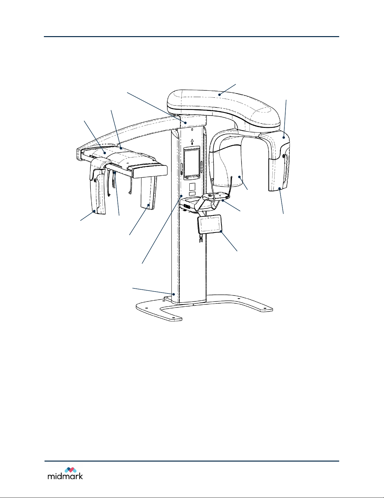
Cephalometric
Sensor
Secondary
Collimator
Cephalostat
Overhead Arm
C-arm
Cephalometric Attachment
Scanning Mechanism
Transit
Panoramic
Sensor
X-ray
Tubehead
Operator Panel
Column,
Fixed Section
Patient
Positioning
Tabl e
Column,
Telescoping
occurrence. The X-ray controller detects the release of the exposure switch simultaneously and
independently from the RTC, and terminates the X-ray power immediately even if the stop command
from RTC is not received.
®
Progeny Vantage
panoramic X-ray system
25
Progey Vantage® Panoramic X-ray System
Technical Service Manual
Theory of Operations
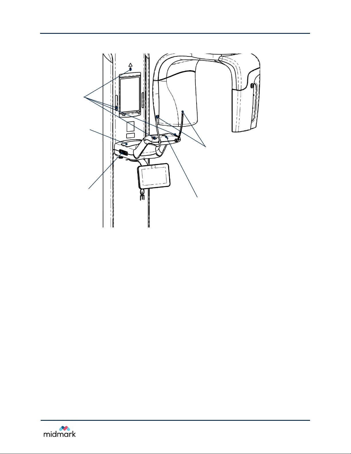
Bite Guide and Chin Rest
Attachment Points
Patient Positioning
Controls
Storage
Compartment
Positioning Wands
Positioning
Lasers
Progeny Vantage® patient positioning table
26

Progey Vantage® Panoramic X-ray System
Technical Service Manual
Troubleshooting Resources
3 Troubleshooting Resources
In this Chapter
• Obtaining Assistance through Remote Access
•
Service Kit
•
Message Center
•
Error Logs
Wiring Diagrams
•
•
Printed Circuit Boards
•
Troubleshooting with Printed Circuit Boards
•
Network Communications
Obtaining Assistance through Remote Access
Remote access enables technical support to have access to a Progeny Vantage® panoramic X-ray
system while the service technician is present at the machine.
®
1. Permission from the user is required for access to the Progeny Vantage
®
2. In order to gain access, a connection from the Progeny Vantage
to the Internet is necessary.
.
3. The service engineer must be present at the location.
4. With the active participation of technical support, the “on-site” person will use the operator panel
to gain access to the Internet and log on to a remote access website. Remote access may require
the downloading and activation of a short application program from the website.
5. Once communications are established, technical support will be able to review the content of the
Progeny Vantage
device. Technical support will not be able to facilitate all manner of repairs remotely. Technical
support will be able to review historical events and make recommendations as to the next course
of action. The “on-site” participant must be able to perform the repairs or adjustments in order to
complete the task.
®
Message Center, see images, and make limited changes in the settings of the
Service Kit
Midmark offers a service kit for the alignment and image evaluation of the Progeny Vantage®
panoramic X-ray system that is available through the technical support. The service kit contains the
following fixtures and tools:
• Positioning Laser Alignment Fixture
• X-ray Source Alignment Fixture
• C-arm Calibration Setup Fixture
• Copper Filter
• Zero Position Pins
• Laser Module Assembly
27

Progey Vantage® Panoramic X-ray System
Technical Service Manual
Troubleshooting Resources
• Projection Head Kit
• Molteni Phantom
Message Center
The Message Center screen is an interactive screen on the operator panel that displays up to
100 error messages for the components of the Progeny Vantage
are sorted by time, with the most recent at the top of the list.
Tapping a column heading, such as Component, sorts the messages by that heading. Tapping a
Progeny Vantage
component.
®
component, for example the telescoping column, highlights all messages for the
Message Center Screen
®
Panoramic system. The messages
Messages also appear as pop-ups on the operator panel, as illustrated below.
Pop-up Message
Accessing the Message Center
The Message Center is accessed from the Options screen, from the SAFE or OFFLINE screens, and from
a pop-up message screen.
28
Progey Vantage® Panoramic X-ray System
Technical Service Manual
Troubleshooting Resources
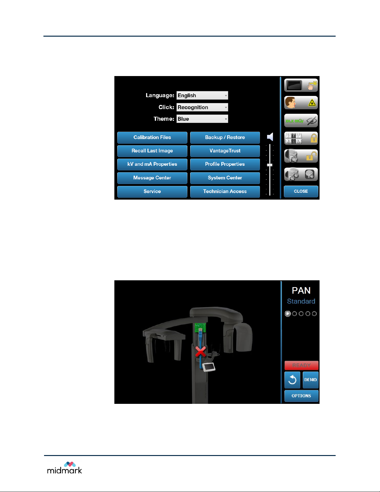
To Access the Message Center from the Options Screen
1. On the Acquisition Setup screen, tap Options to display the Options screen.
Options Screen
2. Tap the Message Center button.
To Access the Message Center from the SAFE or OFFLINE Screens
The SAFE and OFFLINE screens are not directly accessible. The SAFE screen is transitional and
appears when the Progeny Vantage
the operator panel is disconnected from the computer workstation.
On the SAFE screen, tap the Message Center icon to display the Message Center screen.
SAFE Screen
®
system is trying to recover. The OFFLINE screen appears when
29
Progey Vantage® Panoramic X-ray System
Technical Service Manual
Troubleshooting Resources
On the OFFLINE screen, tap the Message Center icon to display the Message Center screen.
OFFLINE Screen
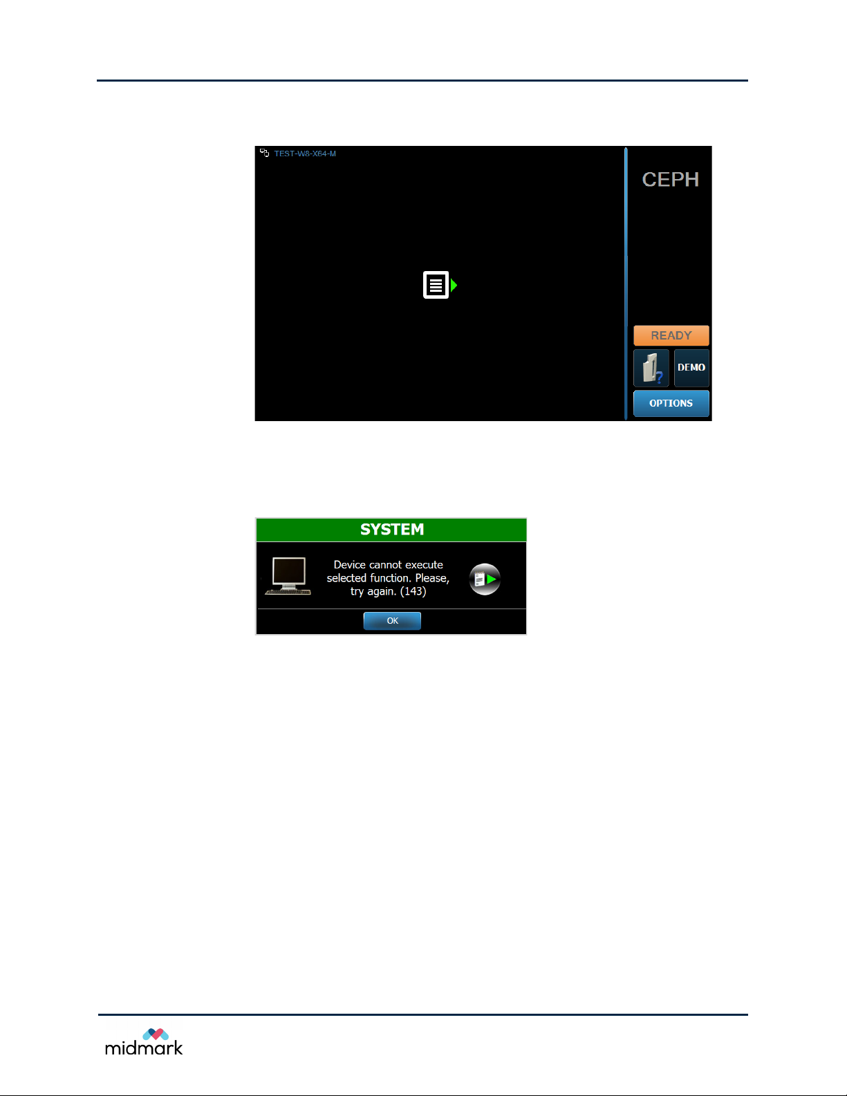
To Access the Message Center from a Message Screen
On the message screen, tap the Message Center icon.
Message Screen
Error Codes
This section lists all the Progeny Vantage® error codes, including system and subsystem errors for
the RTC. These codes help in troubleshooting when trying to pinpoint the source of a problem.
Error codes will either state a condition or offer a direction to investigate. In the case of directly stated
conditions, follow the instruction. In the case of coded messages that indicate a direction to
investigate, review the content of the Message Center for guidance.
Error messages may refer to a node number based on the assigned motor controller address for
communication with RTC as listed below:
• C-arm arm motor is referenced as Node 0.
• X-axis motor is referenced as Node 1.
• Y-axis motor is referenced as Node 2.
• Collimator motors are referenced as Node 3.
• Wand motor is referenced as Node 4.
• Cephalometric motor is referenced as Node 5.
30
 Loading...