

Page 1
PowerVac
Go To Table Of Contents
Next
Style B
®
Model Numbers:
Single Vac Units
P3
P5
P7
Twin Vac Units
P6
P10
P14
Service and
Parts Manual
Earlier Version Current Version
FOR USE BY MIDMARK TRAINED TECHNICIANS ONLY
Part No. 004-0494-00 Rev. AA7 (5/13/19)
Page 2

GENERAL INFORMATION
Back
Next
Symbols ....................................iii
Ordering Parts ......................... iii
Serial Number Location .......... iii
Specifications ........................... iv
Model Identification /
Compliance Charts: ................. v
Warranty Information............... vi
TESTING & REPAIR - continued
cont.
Section B -
General Information
ACCESS PROCEDURES
TROUBLESHOOTING
Vacuum System ....................... A-2
Electrical System Operation
Power to System .................................
Wall Switch On ................................... A-4
Section A
Bottom Float contact Closed .............. A-5
Middle Float Contact Closed ............. A-6
Top Float Contact Closed ................... A-7
Liquid Evacuation Pump
(Accessory) ..............................
A-3
A-11
TESTING & REPAIR
Belt ............................................ B-2
Check Valve .............................. B-6
Vacuum Relief Valve................. B-9
Exhaust .....................................B-12
Float .......................................... B-15
Section B
Low Voltage .............................. B-18
Door Limit Switch &
Circuit Breaker (On/Off Switch)
.............................................. B-21
Contactor .................................. B-26
Fuse........................................... B-28
Table Of Contents
Relay.......................................... B-31
Transformer .............................. B-34
FOR USE BY MIDMARK TRAINED TECHNICIANS ONLY
Section C
WIRING DIAGRAMS
Section D
EXPLODED VIEWS / PARTS LISTS
Section E
Liquid Evacuation Pump
Section E
* Indicates multiple pages due to model / serial number break(s)
Fan..........................................B-37
Gauge ..................................... B-41
Motor ......................................B-43
Capacitor ................................B-44
Pump ......................................B-50
Liquid Evacuation Pump
(Accessory) ............................
Separator Tank ....................... B-58
Front Cover ............................ C-2
Top Cover ............................... C-3
Electrical Cover ...................... C-4
Back Cover (Previous Tank)... C-5
Back Cover (Large Tank) ........ C-6
PowerVac
Liquid Evacuation Pump
(Accessory) ............................
PowerVac® Single Models
(P3, P5, P7) .............................
PowerVac ® Twin Models
(P6, P10, P14) .........................
(Accessory) ...........................
®
.................................................. D-2*
B-53
D-4
E-2*
E-3*
E-4*
Page 3
Symbols
AA158000-1i
0
5
1
0
1
5
2
0
2
5
-
3
0
Back
Go To Table Of Contents
Next
General Information
Ordering Parts
WARNING
Indicates a potentially hazardous situation which
could result in serious injury if not avoided.
The following information is required when ordering parts:
• Serial number & model number
• Part number for desired part.
[Refer to Exploded Views / Parts Lists section]
CAUTION
Indicates a potentially hazardous situation which may
result in minor or moderate injury if not avoided. It may also be
used to alert against unsafe practices.
Equipment Alert
Indicates a potentially hazardous situation which
could result in equipment damage if not avoided.
In Section A, test the components in the order indicated.
(ex.
1st
then,
The symbols below may be used in this manual to represent
the operational status of table functions and components.
Refer to Section B for component testing procedures.
Indicates the function / component is working properly.
No action required.
2nd
)
Non-warranty parts orders may be faxed to Midmark using
the Fax Order Form in the back of this manual.
For warranty parts orders, call Midmark's Technical Service
Department with the required information.
Hours: 8:00 am until 5:00 pm EST [Monday - Friday]
Phone: 1-(800)-Midmark
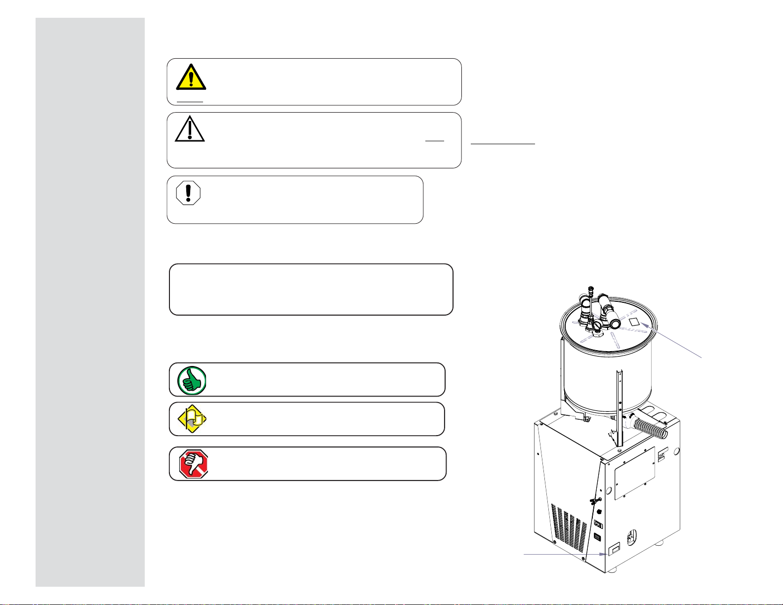
Model / Serial Number Location
Tank Serial
Number
General Information
Indicates the function / component is working,
but a problem exists.
Indicates the function / component is not working at all.
Base Serial
Number
© Midmark Corporation 2006 SF-1873
Rev 9/10/18
iii
Page 4

General Information
Model
P3
Model
P5
Model
P7
Model
P6
Model
P10
Model
P14
Evacuation Control
Box (Optional)
Max Users
3-5 5-7 7-10 6-10 10-14 14-20
N/A
Vac Unit
H x W x D
26" x 19.5" x 18.5" 26" x 19.5" x 18.5" 26" x 19.5" x 18.5" 26" x 39" x 18.5" 26" x 39" x 18.5" 26" x 39" x 18.5"
N/A
Separator
H x W x D
32" x 22" x 22" 32" x 22" x 22" 32" x 22" x 22" 32" x 22" x 22" 32" x 22" x 22" 32" x 22" x 22"
5" x 5.5" x 6"
Actual Weight (lbs)
Vac Unit - 355
Separator - 47
Vac Unit - 355
Separator - 47
Vac Unit - 355
Separator - 47
Vac Units - 710
Separators - 94
Vac Units - 710
Separators - 94
Vac Units - 710
Separators - 94
2
Total HP 222444N/A
Voltage 208 / 230 208 / 230 208 / 230 208 / 230 208 / 230 208 / 230 115 VAC
Amps 11.4 11.4 11.4 22.8 22.8 22.8 3
Hertz 60 60 60 60 60 60 60
Recommended
Breaker Size (Amps)
(Min. 20 Amp ea.)
30 30 30 2 x 30 2 x 30 2 x 30
15
Inlet Connection Size
(in.)
1 1/2" 1 1/2" 1 1/2" 2" 2" 2"
N/A
Fuses
1/8 A, 250V
Type T
1/8 A, 250V
Type T
1/8 A, 250V
Type T
1/8 A, 250V
Type T
1/8 A, 250V
Type T
1/8 A, 250V
Type T
1/4A, 250V, Type T
3A, 250V, Type T
Drain Connection Size
(in.)
1 1/2" 1 1/2" 1 1/2" 1 1/2" 1 1/2" 1 1/2"
N/A
Back
Go To Table Of Contents
Next
Weights, Dimensions, Electrical Specifications
Classifications: Class 1, Type B Applied Part
iv
© Midmark Corporation 2006 SF-1873
Rev. 9/10/18
Page 5

General Information
UL 60601-1
CAN/CSA 22.2,
#601.1-M90
VAC Amps Cycles (Hz)
P3
PowerVac® Dry Vacuum
System - Single - 3 - 5 User
V x x 230 11.4 60
P5
PowerVac® Dry Vacuum
System - Single - 5 - 7 User
V x x 230 11.4 60
P7
PowerVac® Dry Vacuum
System - Single - 7 - 10 User
V x x 230 11.4 60
P6
PowerVac® Dry Vacuum
System - Twin - 6 - 10 User
V x x 230 22.8 60
P10
PowerVac® Dry Vacuum
System -Twin - 10 - 14 User
V x x 230 22.8 60
P14
PowerVac® Dry Vacuum
System - Twin - 14 - 20 User
V x x 230 22.8 60
Complies To:
Model
Description
Serial Number
Prefix
Electrical Supply Requirements:
Back
Go To Table Of Contents
Next
Model Identification / Compliance Chart - PowerVac
®
© Midmark Corporation 2006 SF-1873
Rev 9/10/18
v
Page 6

General Information
Back
Go To Table Of Contents
Next
Warranty Information
LIMITED WARRANTY
SCOPE OF WARRANTY
Midmark Corporation (“Midmark”) warrants to the original purchaser its new PowerVac® products and components (except for components not warranted
under “Exclusions”) manufactured by Midmark to be free from defects in material and workmanship under normal use and service. Midmark’s obligation under
this warranty is limited to the repair or replacement, at Midmark’s option, of the parts or the products the defects of which are reported to Midmark within the
applicable warranty period and which, upon examination by Midmark, prove to be defective.
APPLICABLE WARRANTY PERIOD
The applicable warranty period, measured from the date of installation for the original user, shall be five (5) years or 10,000 usage hours (whichever comes
first) for all warranted products and components and ten (10) years or 20,000 usage hours (whichever comes first) for the pump only.
EXCLUSIONS
This warranty does not cover and Midmark shall not be liable for the following: (1) repairs and replacements because of misuse, abuse, negligence,
alteration, accident, freight damage, or tampering; (2) products which are not installed, used, and properly cleaned as required in the Midmark “Installation”
manual and or PowerVac
manufactured by Midmark; (5) charges by anyone for adjustments, repairs, replacement parts, installation, or other work performed upon or in connection
with such products which is not expressly authorized in writing in advance by Midmark.
EXCLUSIVE REMEDY
Midmark’s only obligation under this warranty is the repair or replacement of defective parts. Midmark shall not be liable for any direct, special, indirect,
incidental, exemplary, or consequential damages or delay, including, but not limited to, damages for loss of profits or loss of use.
®
Care Guide for this applicable product; (3) products considered to be of a consumable nature; (4) accessories or parts not
NO AUTHORIZATION
No person or firm is authorized to create for Midmark any other obligation or liability in connection with the products.
THIS WARRANTY IS MIDMARK’S ONLY WARRANTY AND IS IN LIEU OF ALL OTHER WARRANTIES, EXPRESS OR IMPLIED. MIDMARK MAKES NO IMPLIED
WARRANTIES OF ANY KIND INCLUDING ANY WARRANTIES OF MERCHANTABILITY OR FITNESS FOR ANY PARTICULAR PURPOSE. THIS WARRANTY IS LIMITED TO
THE REPAIR OR REPLACEMENT OF DEFECTIVE PARTS.
vi
Page 7
Troubleshooting
Go To Page:
Back
Go To Table Of Contents
Next
Troubleshooting
5
1
0
2
0
1
5
2
5
0
3
0
Function / System Page
Vacuum System ................................... A-2
Electrical System Operation
Power to System......................... A-3
Wall Switch On ........................... A-4
Bottom Float Contact Closes ...... A-5
Middle Float Contact Closes ....... A-6
Top Float Contact Closes ........... A-7
Liquid Evacuation Pump.......................A-11
Models:
Serial Numbers:
AA220500
Section A
© Midmark Corporation 2006 SF-1873
Rev 2/08
A-1
Page 8
Troubleshooting
Back
Go To Table Of Contents
Next
Go To Page:
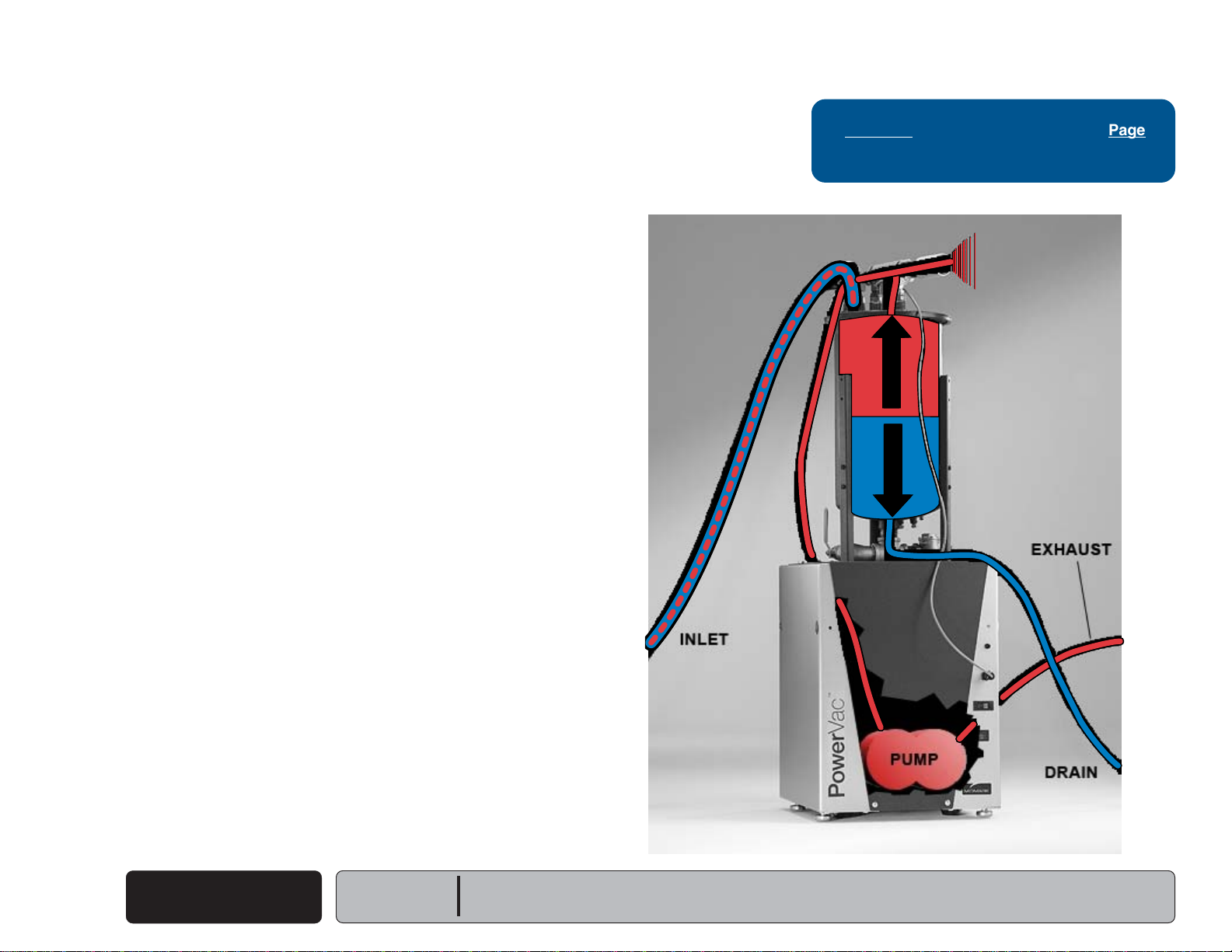
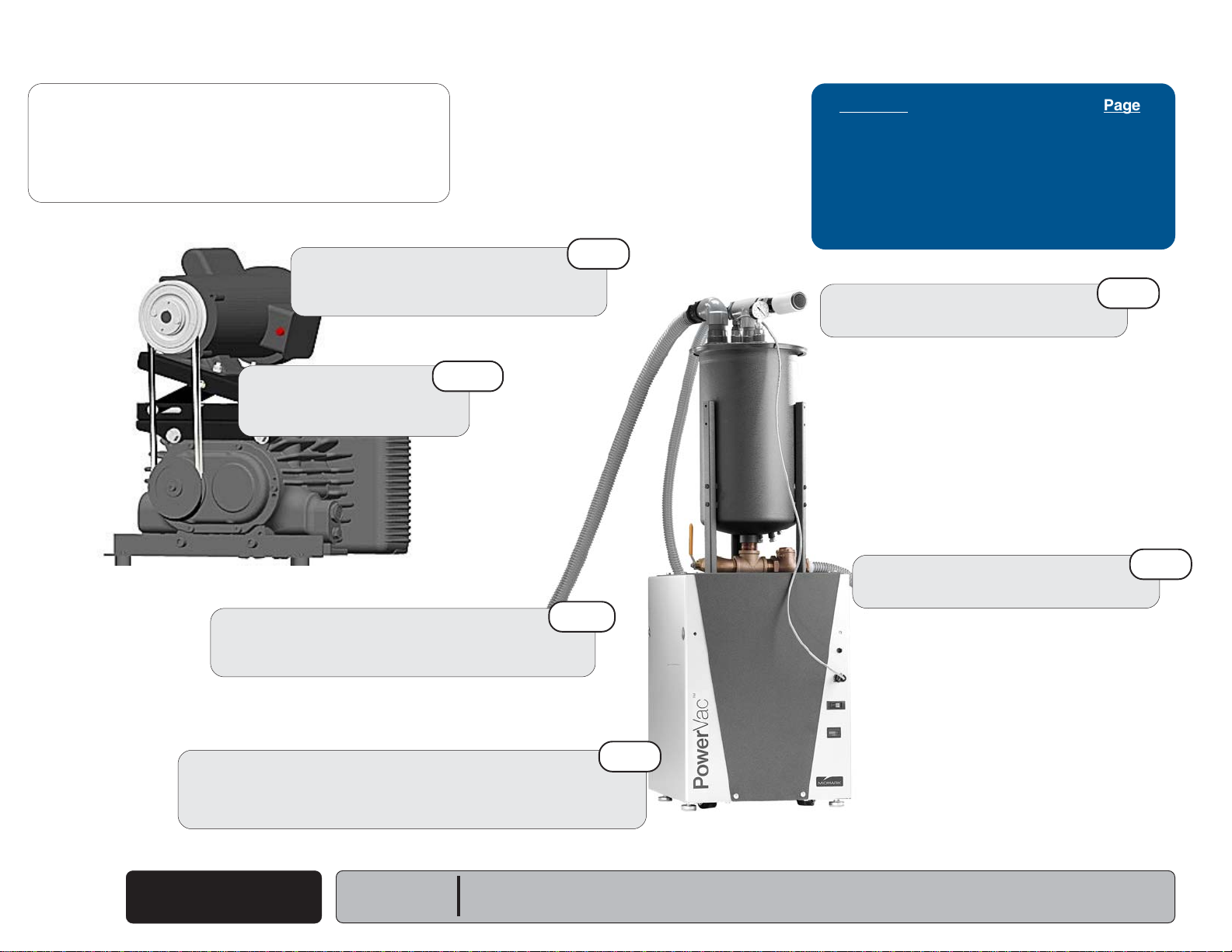
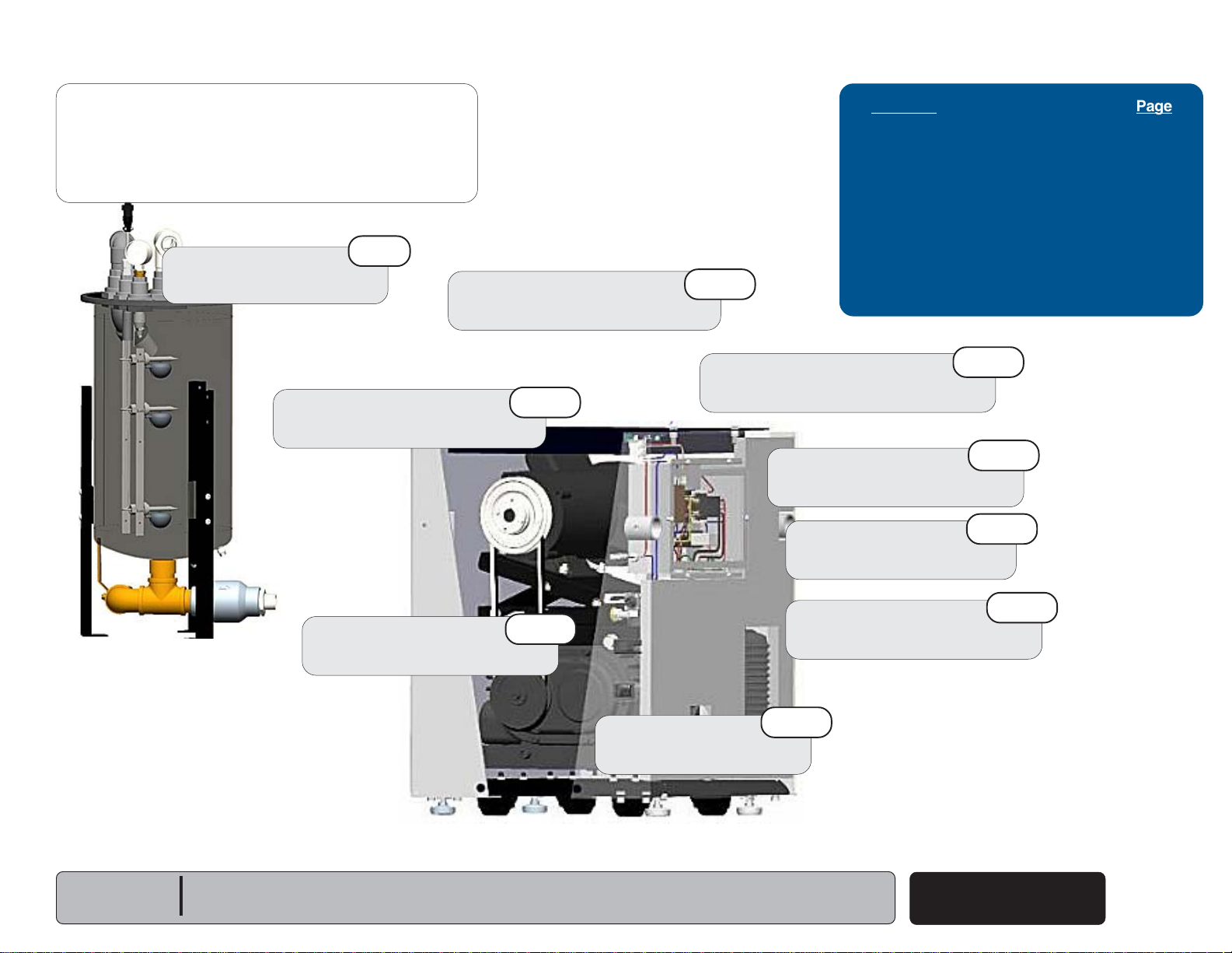
Vacuum System Operation
Operatory waste (air, solids and liquids) is pulled into the separator
through the inlet hose by the rotary claw pump in the vacuum base unit.
Air is separated from liquids and solids. Air then flows into the pump and
out through the exhaust hose.
Refer To: Page
Low or No Suction ................................ A-9
Earlier Version Shown
Fresh air is pumped in through the Vacuum Relief Valve to the pump and
out through the exhaust. (When ports are opened in the operatories the
VRV closes to compensate.)
The check valve connected below the drain port allows the unit to drain
liquids and solids upon removal of vacuum from the chamber when the
pump / motor shuts off.
The fan(s), hour meter and vacuum pump start to run when power is
supplied by the wall switch. The fan(s) and hour meter then begin to cycle
with the vacuum pump / motor. The float switches control the pump motor
by a 24 vac relay via motor contactor.
The upper and lower reed switch floats interact as a latching circuit with
the internal relay to release upon drain below the bottom float.
Air
Liquids
Fresh Air
Intake
Fr
A-2
© Midmark Corporation 2006 SF-1873
Vacuum System
Rev 9/10
Models:
Serial Numbers:
All
Page 9

Troubleshooting
Back
Go To Table Of Contents
Next
Go To Page:
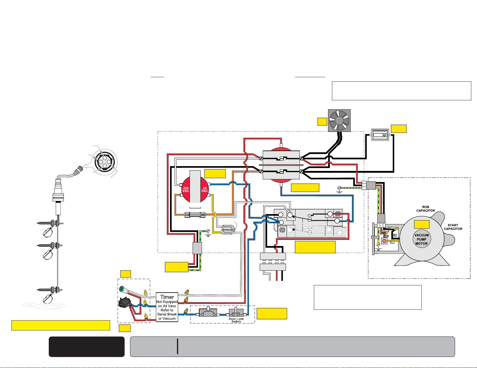
Electrical System
(Power to System Wall Switch Open All Float Switches Open)
• Power (230 VAC) is on supplying Line Voltage to the Vacuum Pump Electrical System.
• 230 V is applied to the 230 V / 24 V Transformer energizing it.
• 24 V is applied from one side of Transformer, to the Terminal Block.
• From the Terminal Block, 24 V is applied to Terminal 6 of CR1 Relay, thru CR1 normally
closed contacts (6 & 2) to one side of the coil on Contactor “C”, also to J1 & J2 Plug
(pin 1), and thru the Timer to one side of the Wall On / Off Light.
• 24 V is also applied thru the closed Door Limit Switch,Circuit Breaker & Timer to one
side of the Wall On/Off Switch.
VACUUM PUMP ELECTRICAL SYSTEM
Common
Top
Float
Middle
Float
Bottom
Float
Bottom
Float
AA160800i
Top
Float
3
Middle
Float
4
2
1
Transformer
Fuse F1
BK
RD
WH
RD
BL
Energized
GN/YL
Circuit
Breaker
YL
Light
On
On/Off
Light
Remote
Wall
Switch
Switch
On
WH
Transformer
OR
230 VAC
Power On
WH
RD
WH
BL
BL
RD
RD
RD
WH
RD
BL
SEPARATOR FLOAT
SWITCH ASSEMBLY
Earlier Version HasThree
Reed Switch Floats.
The Middle Float in
Current Version
is Not Used and
No Longer Installed
Contacts
Open
Contacts
Open
Contacts
Open
Water Level
Water Low, All Float Switches Open
BL
WH
YL
OR
Jumper
Terminal
Block
BL
Refer To: Page
Motor will not Run ................................. A-10
Motor Cutting Out ................................. A-11
NOTE:
Some units have dual fans that are wired in parallel.
FAN
Fan
Off
RD
Contacts
RD
WH
BK
OR
RD
BL
WH
BL
RD
BL
WH
WH
1
1
BL
WH
To J1 or J2 Plug on
Evacuation Board
Separation Tank
Open
WH
BK
BL
RD
2
2
RD BK
or
to Float on
CONTACTOR
"C"
Contacts
Open
Power Removed From
Coil, Contacts Open.
BL
WH
Coil
7
6
Coil
8
Coil
5
WH
BK
3
4
4
3
BK
BK
RD
BK
BK
BK
CR1 (Float Switch) RELAY
Contacts Open
CR1 Coil Not Energized
Contacts Remain in
Same Position
BK
BK
GN/YL
BL
RD
RD
4
BL
2
3
BL
1
RD
NOTE:
Circuit Breaker &
BL
Door Limit Switch
Closed
Manual reset button on earlier versions,
automatic reset on current versions.
RD
HOUR
METER
HOURS
BK BK
Thermal
Reset
Meter
Stopped
Pump
Stopped
AA2480i
Models:
Serial Numbers:
All
Power to System
© Midmark Corporation 2006 SF-1873
Rev 11/2/15
A-3
Page 10
Troubleshooting
Back
Go To Table Of Contents
Next
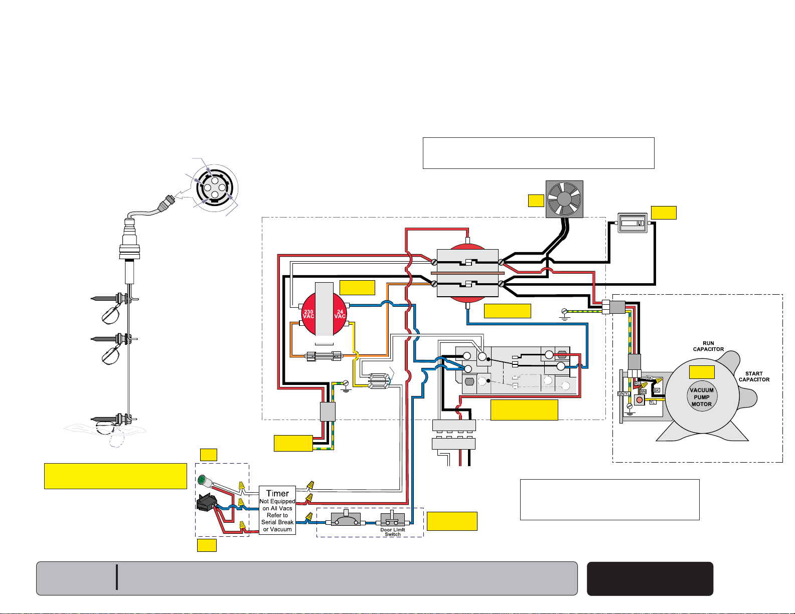
Electrical System
- continued (Wall Switch On, Power to System, All Float Switches Open)
• Remote Wall Switch is turned on, the On / Off Light comes on.
• 24 V is applied to the other side of the coil of Contactor “C”, energizing the coil and closing its
contacts.
• The Fan(s), Hour Meter, and Vacuum Pump run.
Electrical System
- continued (Wall Switch OFF
,
Power to System, All Float Switches Open, Timer ON)
• Remote Wall Switch is turned off, the Timer turns on and starts to measure two hours.
• The Timer will run the Vacuum for one minute every two hours while the Remote Wall Switch is
turned off by completing the 24 V circuit to the Contactor "C" coil.
VACUUM PUMP ELECTRICAL SYSTEM
SEPARATOR FLOAT
SWITCH ASSEMBLY
Earlier Version Shown
Earlier Version HasThree
Reed Switch Floats.
The Middle Float in
Current Version
is Not Used and
No Longer Installed
Contacts
Open
Contacts
Open
Contacts
Open
Water Level
Water Low, All Float Switches Open
Top
Float
Middle
Float
Bottom
Float
Common
Bottom
Float
AA160800i
Top
Float
3
Middle
Float
4
2
1
Transformer
Energized
BL
YL
WH
BK
YL
GN/YL
WH
RD
BL
Circuit
Breaker
OR
Jumper
Terminal
Block
BL
RD
WH
RD
WH
Light
On
On/Off
Light
Remote
Wall
Switch
Switch
On
WH
Transformer
OR
Fuse F1
RD
230 VAC
Power On
WH
RD
WH
BL
BL
RD
RD
RD
WH
RD
BL
RD
RD
WH
BK
OR
BL
BL
BL
WH
1
1
WH
To J1 or J2 Plug on
Evacuation Board
Separation Tank
Circuit Breaker &
BL
Door Limit Switch
Contacts
Closed
WH
BK
BL
RD
2
2
RD BK
or
to Float on
Closed
CONTACTOR
Contacts
BL
Coil
7
Coil
8
Coil
WH
BK
3
4
4
3
"C"
BK
BK
RD
BK
BK
Closed
Coil Energized
Contacts Closed
CR1 (Float Switch) RELAY
WH
Contacts Open
6
5
CR1 Coil Not Energized
Contacts Remain in
Same Position
NOTE:
Some units have dual fans that are wired in parallel.
FAN
Fan
On
BK
BK
BK
GN/YL
BL
RD
RD
4
BL
2
3
BL
1
RD
BK BK
RD
HOUR
METER
HOURS
Thermal
Reset
Meter
Running
NOTE:
Manual reset button on earlier versions,
automatic reset on current versions.
Pump
Running
AA2478i
Wall Switch On
A-4
© Midmark Corporation 2006 SF-1873
Rev 11/2/15
Models:
Serial Numbers:
All
Page 11
Troubleshooting
Back
Go To Table Of Contents
Next
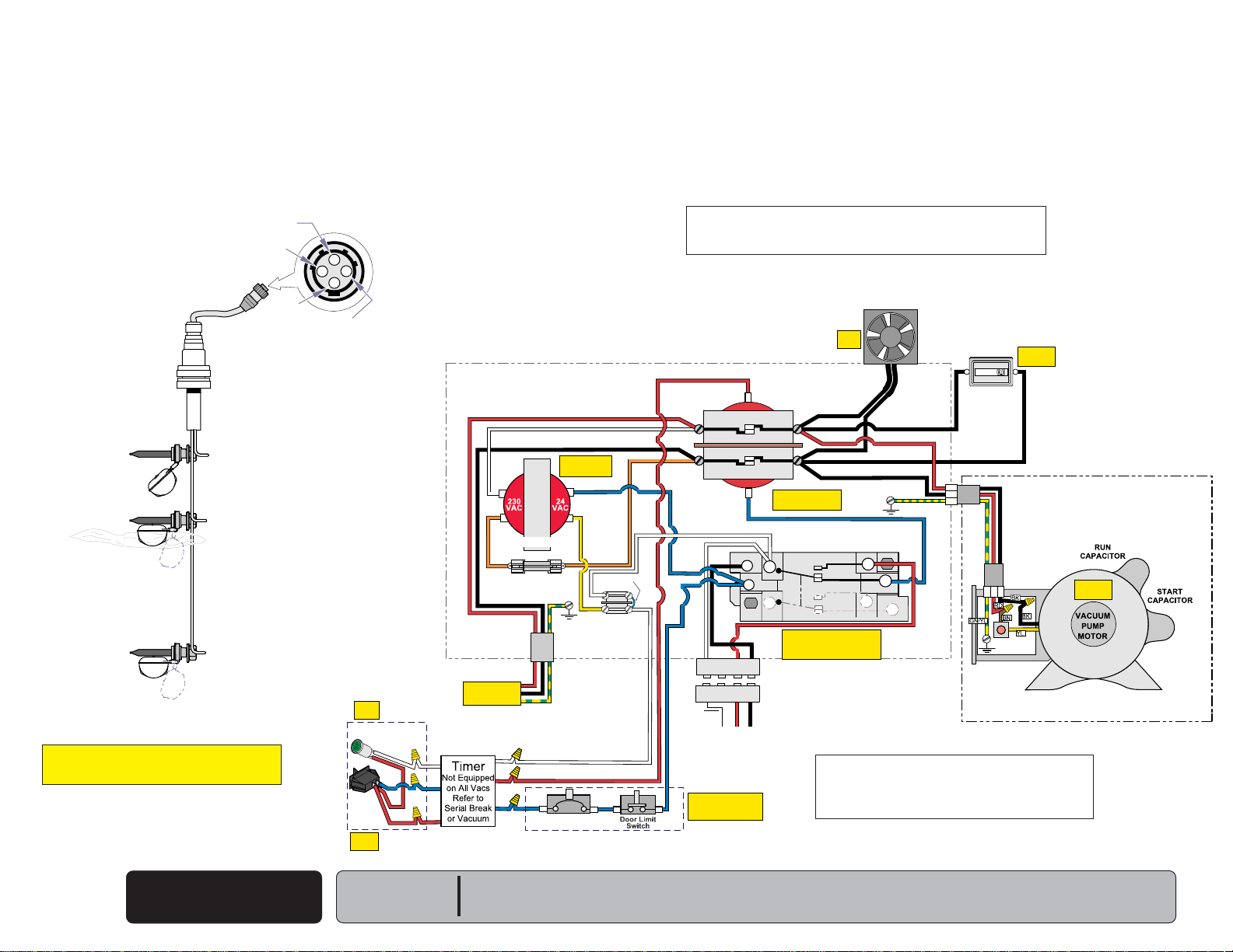
Electrical System
- continued (Water Rises, Bottom Float Switch Closes, Middle and Top Switches Remain Open.)
• Contactor “C” contacts remain closed.
• The Fan(s), Hour Meter, and Vacuum Pump continue to run.
SEPARATOR FLOAT
SWITCH ASSEMBLY
Earlier Version Shown
Earlier Version HasThree
Reed Switch Floats.
The Middle Float in
Current Version
is Not Used and
No Longer Installed
Contacts
Open
Contacts
Open
Contacts
Closed
Water Level
Bottom Float Switch Closed,
Middle and Top Remain Open.
Top
Float
Middle
Float
Bottom
Float
Common
Bottom
Float
Top
Float
AA160801i
3
Middle
Float
Light
On
On/Off
Light
Remote
Wall
Switch
Switch
On
4
2
1
WH
RD
WH
BL
BL
RD
RD
RD
WH
OR
230 VAC
Power On
WH
RD
BL
Transformer
Fuse F1
BK
RD
GN/YL
WH
RD
BL
Breaker
NOTE:
Some units have dual fans that are wired in parallel.
VACUUM PUMP ELECTRICAL SYSTEM
Transformer
Energized
BL
YL
YL
Circuit
WH
Terminal
Block
BL
OR
Jumper
WH
WH
RD
RD
Contacts
WH
BK
OR
RD
BL
WH
BL
RD
BL
WH
1
1
WH
To J1 or J2 Plug on
Evacuation Board
Separation Tank
Circuit Breaker &
BL
Door Limit Switch
Closed
Coil
BK
BL
RD
2
3
2
3
RD BK
or
to Float on
Closed
CONTACTOR
"C"
Contacts
Closed
Contacts Closed
BL
WH
7
6
Coil
8
Coil
5
WH
BK
4
4
Coil Energized
CR1 Coil Not Energized
FAN
Fan
On
BK
BK
RD
BK
BK
BK
CR1 (Float Switch) RELAY
Contacts Open
Contacts Remain in
Same Position
RD
4
2
3
NOTE:
Manual reset button on earlier versions,
automatic reset on current versions.
HOUR
METER
BK
BK BK
RD
BK
GN/YL
BL
RD
BL
BL
1
RD
HOURS
Thermal
Reset
Meter
Running
Pump
Running
AA2478i
Models:
Serial Numbers:
All
Bottom Float
Switch Closed
© Midmark Corporation 2006 SF-1873
Rev 11/2/15
A-5
Page 12
Troubleshooting
Back
Go To Table Of Contents
Next
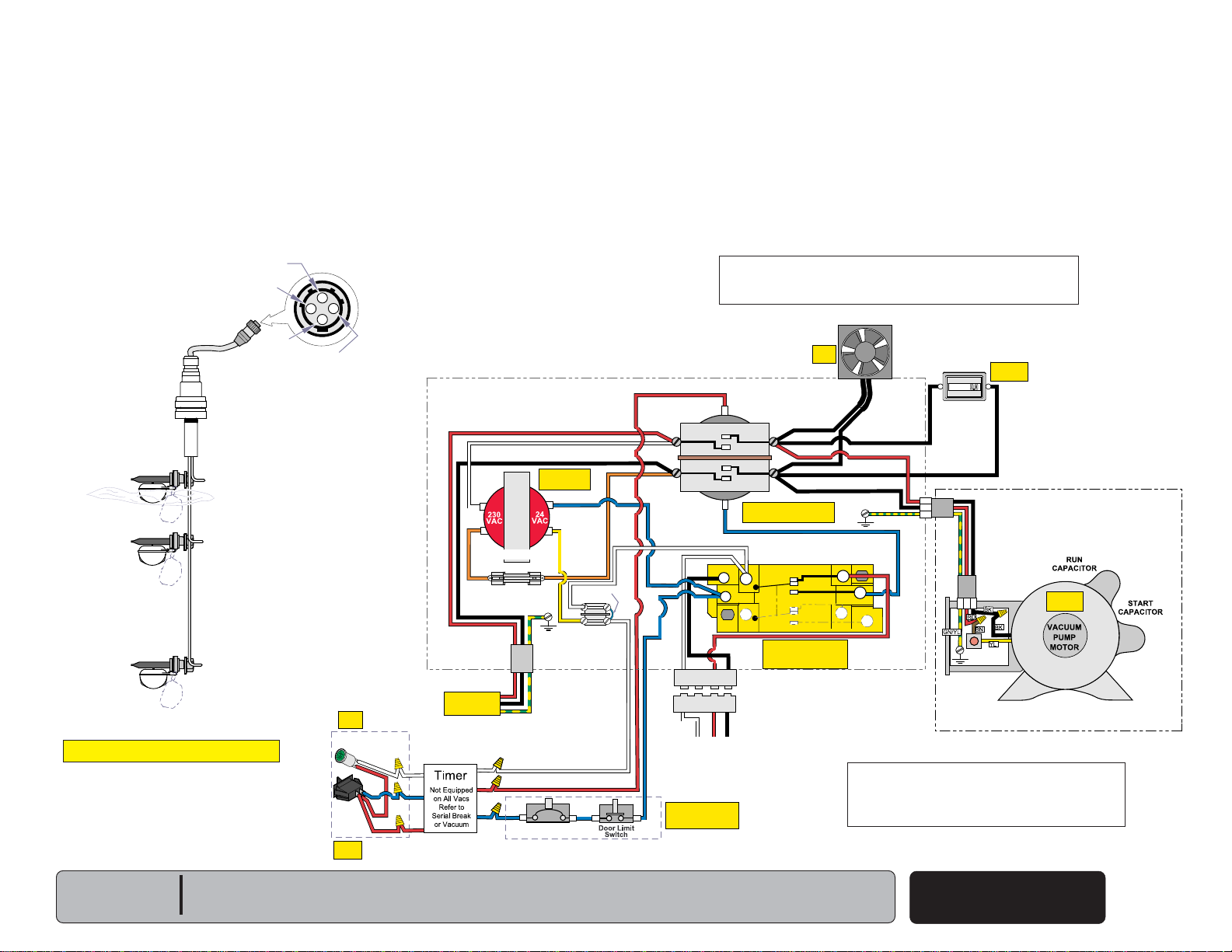
Electrical System
- continued (Water Reaches Middle Float, Middle and Bottom Float Switches are Closed, Top Switch Remains Open.)
• Contactor “C” contacts remain closed.
• The Fans, Hour Meter, and Vacuum Pump continue to run.
Top
Float
Middle
Float
Bottom
Float
Common
AA160802i
Bottom
Float
Top
Float
4
3
Middle
Float
1
2
Light
On
On/Off
Light
Remote
Wall
Switch
Switch
On
WH
RD
BL
RD
RD
SEPARATOR FLOAT
SWITCH ASSEMBLY
Earlier Version Shown
Earlier Version HasThree
Reed Switch Floats.
The Middle Float in
Current Version
is Not Used and
No Longer Installed
Contacts
Open
Contacts
Closed
Water Level
Contacts
Closed
Middle and Bottom Float Switches
are Closed, Top Remains Open.
NOTE:
Some units have dual fans that are wired in parallel.
Fan
On
FAN
HOUR
METER
BK
BK BK
RD
BK
GN/YL
BL
RD
RD
4
BL
2
3
BL
1
RD
HOURS
Thermal
Reset
Meter
Running
Pump
Running
AA2478i
VACUUM PUMP ELECTRICAL SYSTEM
RD
RD
WH
Transformer
Fuse F1
BK
RD
WH
RD
BL
Energized
YL
GN/YL
Circuit
Breaker
BL
WH
YL
OR
Jumper
Terminal
Block
BL
WH
WH
Transformer
OR
230 VAC
Power On
WH
BL
RD
WH
RD
BL
BK
OR
RD
BL
WH
BL
RD
BL
WH
1
1
WH
To J1 or J2 Plug on
Evacuation Board
Separation Tank
Circuit Breaker &
BL
Door Limit Switch
Contacts
Closed
WH
BK
BL
RD
2
2
RD BK
or
to Float on
Closed
CONTACTOR
Contacts
BL
Coil
7
Coil
8
Coil
WH
BK
3
4
4
3
"C"
BK
BK
BK
Closed
Coil Energized
Contacts Closed
CR1 (Float Switch) RELAY
WH
Contacts Open
6
5
CR1 Coil Not Energized
Contacts Remain in
Same Position
BK
RD
BK
NOTE:
Manual reset button on earlier versions,
automatic reset on current versions.
A-6
Switch Closed
© Midmark Corporation 2006 SF-1873
Middle Float
Rev 11/2/15
Models:
Serial Numbers:
All
Page 13
Electrical System
Back
Go To Table Of Contents
Next
- continued (Water Reaches Top Float, All Float Switches are Closed.)
• The Top Float Switch sends 24v to the coil of CR1 Float Switch Relay changing the contacts position.
• Power is removed from the coil of Contactor “C”, opening its contacts.
• The Fan(s), Hour Meter, and Vacuum Pump stop running.
• CR1 Float Switch Relay remains energized through its own normally closed tips (6&4) and the bottom float
swich (pin 3) of J1& J2
• The Collection tank starts to Drain, Pump remains off until Bottom Float Switch opens interupting 24v to the
CR1 Float Switch Relay coil.
• CR1 Float Switch Relay returns to its nornal state energizing Contactor "C", the Vacuum Pump, Fan(s) Motors,
and Hour Meter restart .
SEPARATOR FLOAT
SWITCH ASSEMBLY
Earlier Version Shown
Earlier Version HasThree
Reed Switch Floats.
The Middle Float in
Current Version
is Not Used and
No Longer Installed
Contacts
Closed
Water Level
Contacts
Closed
Contacts
Closed
All Float Switches are Closed.
Top
Float
Middle
Float
Bottom
Float
AA160803i
Common
Bottom
Float
Top
Float
3
Middle
Float
4
1
2
Light
On
On/Off
Light
Remote
Wall
Switch
Switch
On
VACUUM PUMP ELECTRICAL SYSTEM
RD
Contacts
RD
Open
WH
Transformer
Fuse F1
BK
RD
WH
RD
BL
GN/YL
Circuit
Breaker
Energized
BL
YL
YL
WH
Terminal
Block
BL
OR
Jumper
WH
WH
Transformer
OR
230 VAC
Power On
WH
RD
WH
BL
BL
RD
RD
RD
WH
RD
BL
BK
OR
RD
BL
WH
RD
BL
BL
WH
1
1
BL
WH
To J1 or J2 Plug on
Evacuation Board
Separation Tank
Circuit Breaker &
BL
Door Limit Switch
WH
Closed
NOTE:
Some units have dual fans that are wired in parallel.
CONTACTOR
Contacts
Open
BL
Coil
BK
7
Coil
8
Coil
BL
WH
RD
BK
2
3
4
4
2
3
RD BK
or
to Float on
Fan
"C"
BK
BK
RD
BK
BK
BK
Power Removed From
Coil, Contacts Open.
CR1 (Float Switch) RELAY
WH
Contacts Open
6
5
CR1 Coil
Energizes
Contacts Change
Positions
Troubleshooting
FAN
RD
HOUR
METER
HOURS
BK BK
Thermal
Reset
Meter
Stops
Off
BK
BK
GN/YL
BL
RD
RD
4
BL
2
3
BL
1
RD
NOTE:
Manual reset button on earlier versions,
automatic reset on current versions.
Pump
Stops
AA2479i
Models:
Serial Numbers:
All
Top Float
Switch Closed
© Midmark Corporation 2006 SF-1873
Rev 11/2/15
A-7
Page 14
Troubleshooting
Back
Go To Table Of Contents
Next
Go To Page:
Vacuum System
Problem: Operatory has low or no suction.
Earlier Version Shown
Will the motor start?
If motor runs go to 2nd check.
If not Refer to Section A - Motor will not run.
Check Belt Tension.
Refer to: Section B - Belt.
(Earlier Version ONLY)
2nd
1st
Refer To: Page
Motor will not Run ................................. A-9
Belt ............................................... B-2
Check Valve ......................................... B-6
Vacuum Relief Valve ............................ B-9
Exhaust ............................................... B-12
Check Vacuum Relief Valve.
Refer to: Section B - Vacuum Relief Valve.
5th
A-8
with Motor Running
© Midmark Corporation 2006 SF-1873
Check Hoses and Bulkhead Fittings.
Check for leaks, kinks and loose connections in the
hoses, bulkhead fittings and separator lid gasket.
Check Exhaust.
Remove exhaust line to see if suction increases.
Unclog or replace exhaust line if suction increased when checking.
Refer to: Section B - Exhaust
Low or No Suction
Rev 9/10/18
Models:
Serial Numbers:
3rd
All
6th
Earlier Version Shown
Check Drain Line for Suction.
Refer to: Section B - Check Valve.
4th
Page 15
Troubleshooting
Back
Go To Table Of Contents
Next
Go To Page:
Vacuum System
Problem: Motor will not run.
Check Float.
Refer to: Section B - Float
6th
Is Pump locked up?
Refer to: Section B - Pump
Reset Thermal Overload.
Refer to: Section B - Motor
2nd
Refer To: Page
Door Limit Switch................................B-20
Float...................................................B-15
Pump .................................................B-49
Low Voltage .......................................... B-18
Motor ..................................................B-42
Contactor .............................................. B-25
Fuse .................................................. B-27
1st
Check Door Limit Switch.
Refer to: Section B - Door Limit Switch
Check Fuse.
Refer to: Section B - Fuse
Check Relay.
Refer to: Section B - Relay
Relay ................................................ B-30
3rd
5th
7th
Earlier Version Shown
Models:
Serial Numbers:
All
Check Low Voltage.
Refer to: Section B - Low Voltage
4th
Check Motor.
Refer to: Section B - Motor
Earlier Version Shown
Check Contactor.
Refer to: Section B - Contactor
9th
Motor Not Running
© Midmark Corporation 2006 SF-1873
8th
Rev 9/10/18
A-9
Page 16
Troubleshooting
Back
Go To Table Of Contents
Next
Go To Page:
Vacuum System
Problem: Motor cutting out or running at a reduced speed.
RER
1st
4th
Check Equipment Room Temperature.
Temperature should be - 40° to 104° Fahrenheit
- 4 to 37 Celsius
Check Exhaust line and valve.
Refer to: Section B - Exhaust
Refer To: Page
Contactor .............................................. B-25
Pump ....................................................B-44
Exhaust ............................................... B-12
Motor ..................................................B-42
Check Contactor Voltage.
Refer to: Section B - Contactor
2nd
A-10
© Midmark Corporation 2006 SF-1873
Motor Cutting Out
Rev 9/10/18
Models:
Serial Numbers:
All
Earlier Version Shown
Check Motor.
Refer to: Section B - Motor
Is Pump locked up?
Refer to: Section B - Pump
5th
3rd
Page 17
AA158503i
HIGH
VOLTAGE
LOW
VOLTAGE
K4
C1
115
VAC
115
VAC
J4
F3 FUSE
F2 FUSE
F1 FUSE
115 VAC
Supply
Neutral
(Blue)
Line
(Black)
J7
J6
BK
GN
RD
WH
POWER
ON
LIGHT
BL
WH
WH
WH
BK
BL
YL
BK
BK
BR
GN/YL
WH
BK
BL
YL
GN/YL
Grd
J5
PLUG
4
1
2
3
4
3
2
1
K1
RELAY
VACUUM PUMP #1
Top
Float Swt.
Bottom
Float Swt.
RELAY
Contacts
Open
LED
OFF
RELAY
K2
K3
RELAY
Neutral
(Wht)
Line
(Blk)
EVAC.
PUMP
J8
J9
1
4
2
3
Middle
Float Swt.
Common
Top
Float Swt.
Bottom
Float Swt.
To
Separator
Float Assy.
1
4
2
3
BK
GN
RD
WH
Com.
Bottom
Middle
Top
WH
BK
RD
WH
BK
RD
J2
PLUG
2
3
1
1
4
2
3
BK
RD
WH
To Motor Control
(CR1 Relay)
System #2
(Same As
Above J1)
1
4
2
3
Coil (7)
N/O (4)
1
4
2
3
BK
RD
WH
To Motor Control
(CR1 Relay)
System #1
N/O
Com. (6)
WH
RD
BK
J3
Plug
1
2
J1
PLUG
2
3
1
Light
On
115 VAC
Power On
Transformer
Energized
24 VAC
On
115 VAC
Power On
Contacts
Closed
VACUUM PUMP #2
Contacts
Closed
FLOATS
Contacts
Closed
EVAC. PUMP
LED
ON
Evac.
Pump
Swt.
LED
ON
115 VAC
Power On
LIQUID
EVACUATION
PUMP
Pump
On
115 VAC
Power On
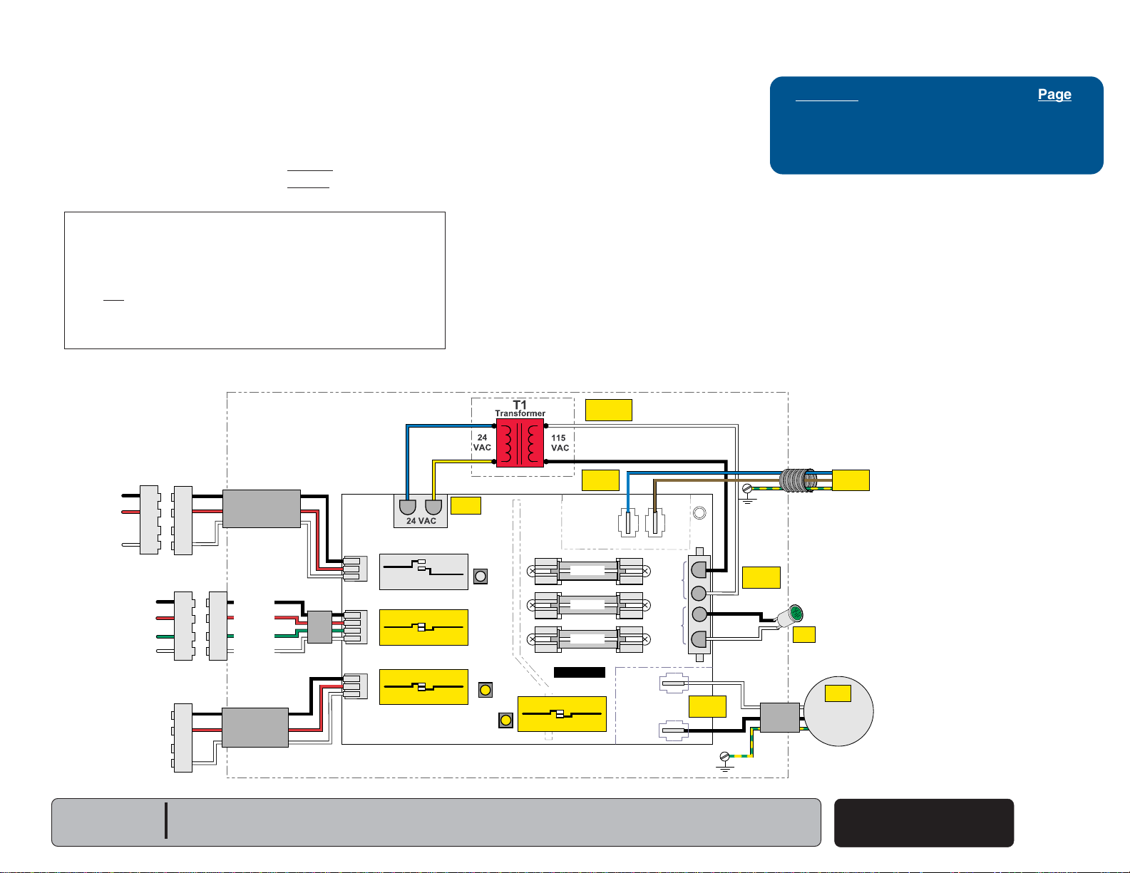
Electrical System for Accessory - Liquid Evacuation Pump
Back
Go To Table Of Contents
Next
Go To Page:
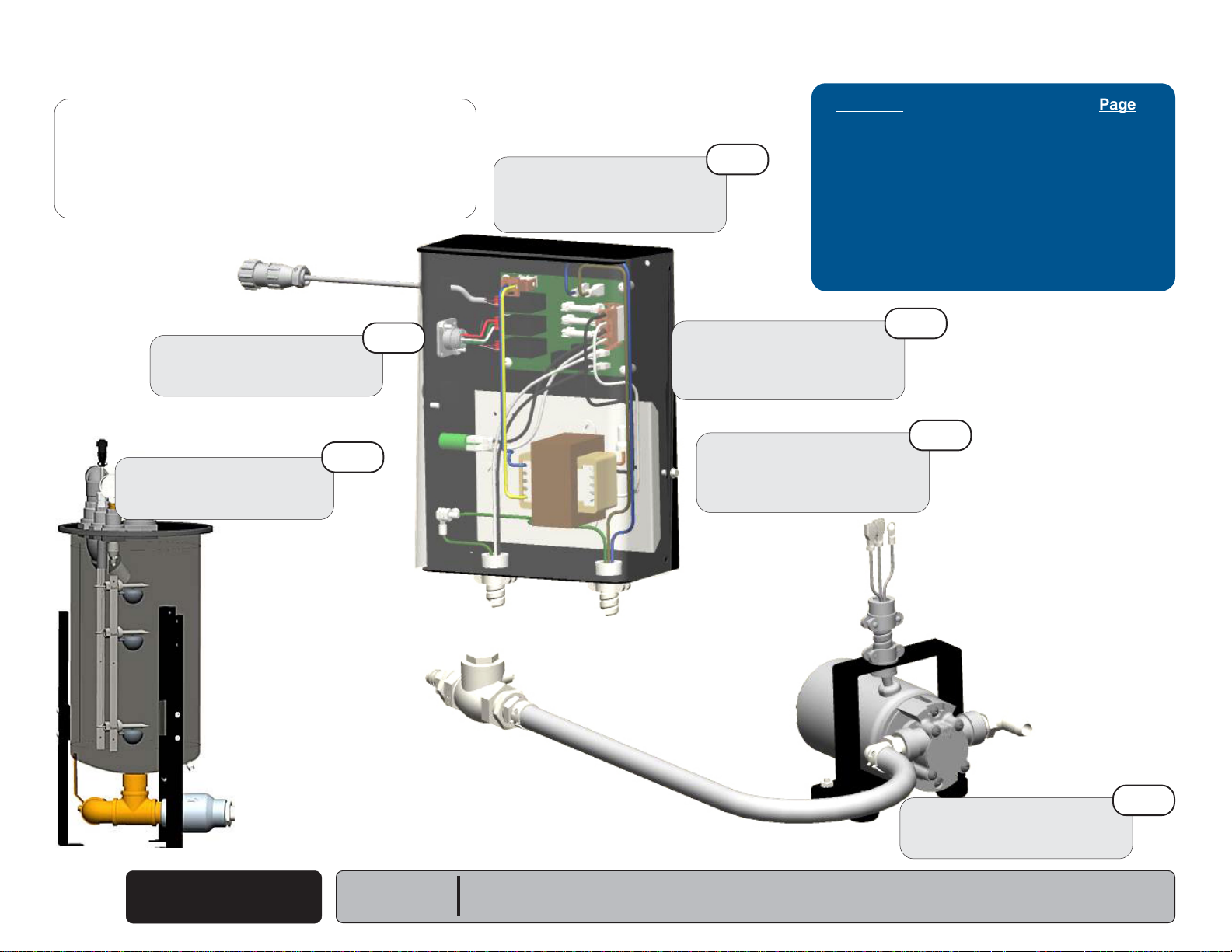
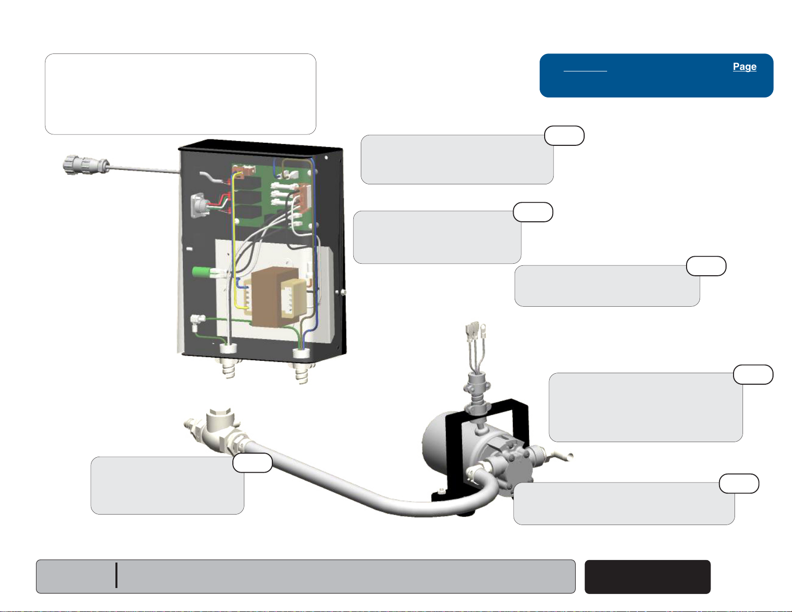
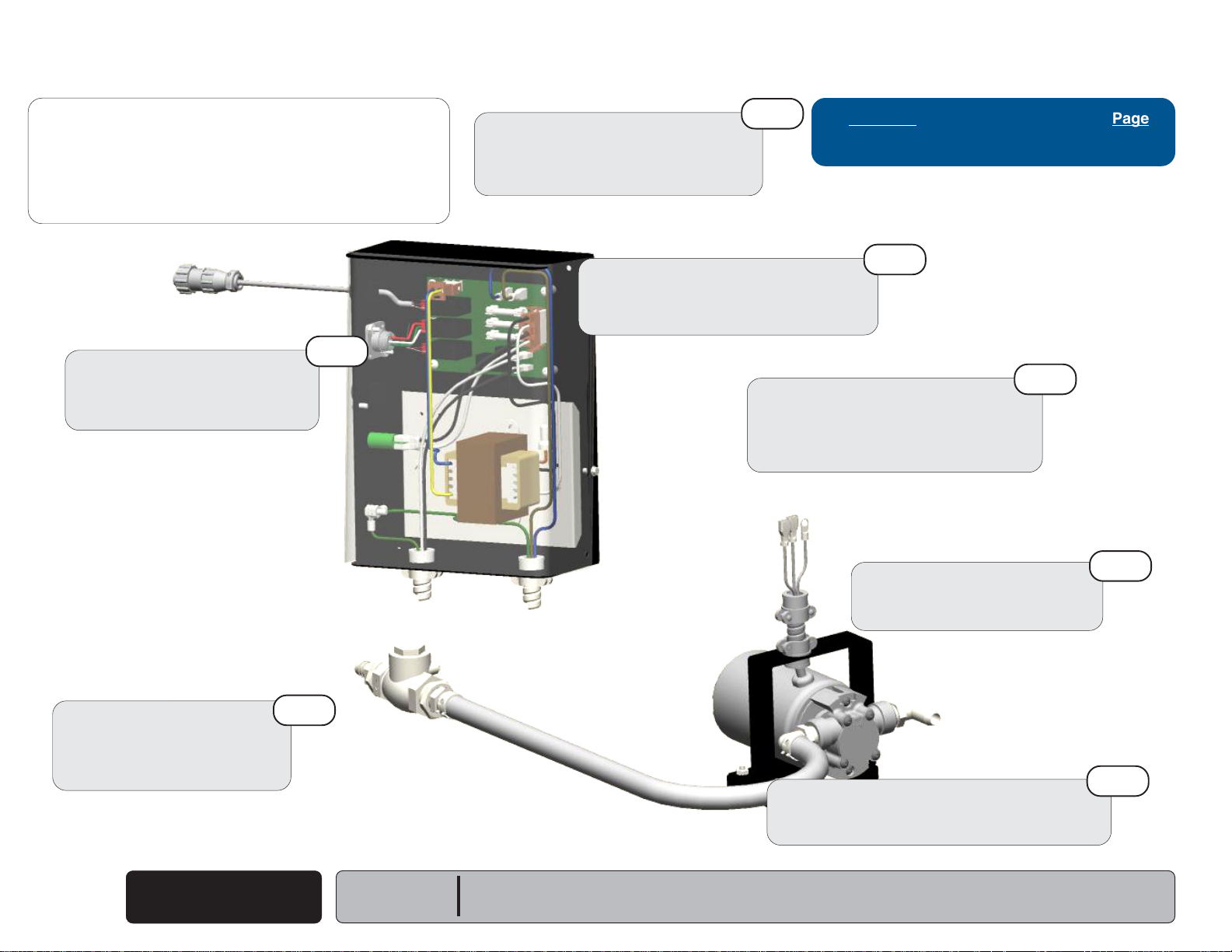
The Liquid Evacuation Pump is an optional accessory for the PowerVac®.
• 115 VAC is applied to the 115V / 24V Transformer energizing it.
• 24 VAC is applied from one side of the Transformer to the J3 plug.
• When the water level reaches the
• When the water level reaches the
Power is supplied to J8 and J9 terminals, energizing the Liquid Evacuation Pump.
NOTE:
The Liquid Evacuation Pump will continue to run until the water
level drops below the
contacts.
If the
Top
float closes, K1 relay contacts close, and its LED is on,
a problem is occurring with the system.
Check for a restriction in the lines, pump not functioning, or PC
board problem.
Liquid Evacuation Pump Electrical System shown when the Bottom & Middle Float Switches are Closed and Pump is running.
Bottom
float switch, opening K3 & K4 relay
Bottom
Middle
float switch, K3 relay contact closes.
float switch, K2 & K4 relay contact close.
(Liquid Evac Pump is Optional)
Optional Liquid Evac Pump Must use a Three Float Assembly
Troubleshooting
Refer To: Page
Evacuation Pump Will Not Run............. A-12
Pump Runs But Will Not Pump ............. A-13
Pump tripping Thermal Overload .......... A-14
Serial Numbers:
Models:
All
Liquid Evac Pump
Electrical
© Midmark Corporation 2006 SF-1873
Rev 9/10/18
A-11
Page 18
Troubleshooting
Back
Go To Table Of Contents
Next
Go To Page:
Evacuation Pump System
Problem: Evacuation Pump will not run.
Check PC Board
Refer to: Section B - Liquid
Evacuation Pump
Check Float Assembly
Refer to: Section B - Float
Assembly
3rd
5th
Check Low Voltage
to PC Board
Refer to: Section B - Liquid
Evacuation Pump
Refer To: Page
Liquid Evacuation Pump
2nd
Check Supply Voltage
to PC Board
Refer to: Section B - Liquid
Evacuation Pump
Check Thermal Motor
Protector
Refer to: Section B - Liquid
Evacuation Pump
Check Supply Voltage ...............B-53-B-56
Check Low Voltage....................B-53-B56
Check Float Assembly....................... B-15
Check Thermal Motor Protector...B-53-B-56
Check PC Board........................B-53-B-56
Check Pump Motor....................B-53-B-56
1st
4th
Earlier Version Shown
A-12
© Midmark Corporation 2006 SF-1873
Evacuation Pump
Will Not Run
Rev 9/10/18
Models:
Serial Numbers:
All
Earlier Version Shown
Check Pump Motor
Refer to: Section B - Liquid
Evacuation Pump
6th
Page 19
Troubleshooting
Back
Go To Table Of Contents
Next
Go To Page:
Evacuation Pump System
Problem: Evacuation Pump runs but does not
remove liquid from Separator.
Check Supply Voltage to Pump
Supply voltage is low.
Refer to: Section B - Liquid Evacuation
Pump
2nd
Check for Obstructions in
Outlet of Separator / Lines.
Refer to: Section B - Liquid
Evacuation Pump
Check Pump Location
Pump should be positioned as close as
possible below the separator.
Refer To: Page
Liquid Evacuation Pump..............B-53-B-56
4th
5th
Check Discharge Line
from Pump
Do not run a discharge head of
greater then 35 ft. (15 Psi).
Models:
Serial Numbers:
All
6th
Earlier Version Shown
Check Suction Line Into Pump
Check for leaks.
Avoid "looping" suction pipe as it could
trap air.
Suction line should not be more than 6 ft.
in length.
Check Evac. Pump Impeller for
Obstructions or Damage.
Refer to: Section B - Liquid Evacuation Pump
Evacuation Pump Runs
but Will Not Pump
© Midmark Corporation 2006 SF-1873
Rev 9/10/18
1st
3rd
A-13
Page 20
Troubleshooting
Back
Go To Table Of Contents
Next
Go To Page:
Evacuation Pump System
Problem: Evacuation Pump Motor keeps tripping
on Thermal Overload.
2nd
Check for Obstructions in
Discharge Line from Pump
Refer to: Section B - Liquid
Evacuation Pump
Check Ambient Temperature
at Motor
Temperature should not exceed 104° F
(40° C) around pump.
Check Supply Voltage to Pump
Supply voltage is low.
Refer to: Section B - Liquid Evacuation
Pump
6th
Check Pump Location
Pump should be positioned as close as
possible below the separator.
Suction line should not be more than 6 ft.
in length.
Refer To: Page
Liquid Evacuation Pump ....................... B-52
1st
5th
Check Discharge Line
from Pump
Do not run a discharge head of
greater then 35 ft. (15 Psi).
Evacuation Pump Keeps
Tripping on Thermal
A-14
© Midmark Corporation 2006 SF-1873
Protector
3rd
Rev 9/10/18
Models:
Serial Numbers:
Earlier Version Shown
All
Motor Thermal Protector
Weak
Replace motor pump.
Check Evac. Pump Impeller for
Obstructions or Damage.
Refer to: Section B - Liquid Evacuation Pump
7th
4th
Page 21
Testing & Repair
Back
Go To Table Of Contents
Next
Go To Page:
Testing & Repair
Components: Page
Belt ....................................................B-2
Check Valve ......................................... B-6
Vacuum Relief Valve ............................ B-9
Exhaust ............................................... B-12
Float ..................................................... B-16
Low Voltage .......................................... B-18
Door Limit Switch &
Circuit Breaker (On/Off Switch) ........... B-21
Contactor ............................................. B-26
Fuse ..................................................... B-28
Relay .................................................... B-31
Transformer ......................................... B-34
Fan ....................................................... B-37
Gauge ................................................... B-41
Motor .................................................... B-43
Pump .................................................... B-50
Liquid Evacuation Pump (Accessory) .. B-53
Separator Tank (Rinse)....................... B-58
Models:
Serial Numbers:
Section B
© Midmark Corporation 2006 SF-1873
B-1
Page 22
Testing & Repair
Back
Go To Table Of Contents
Next
Go To Page:
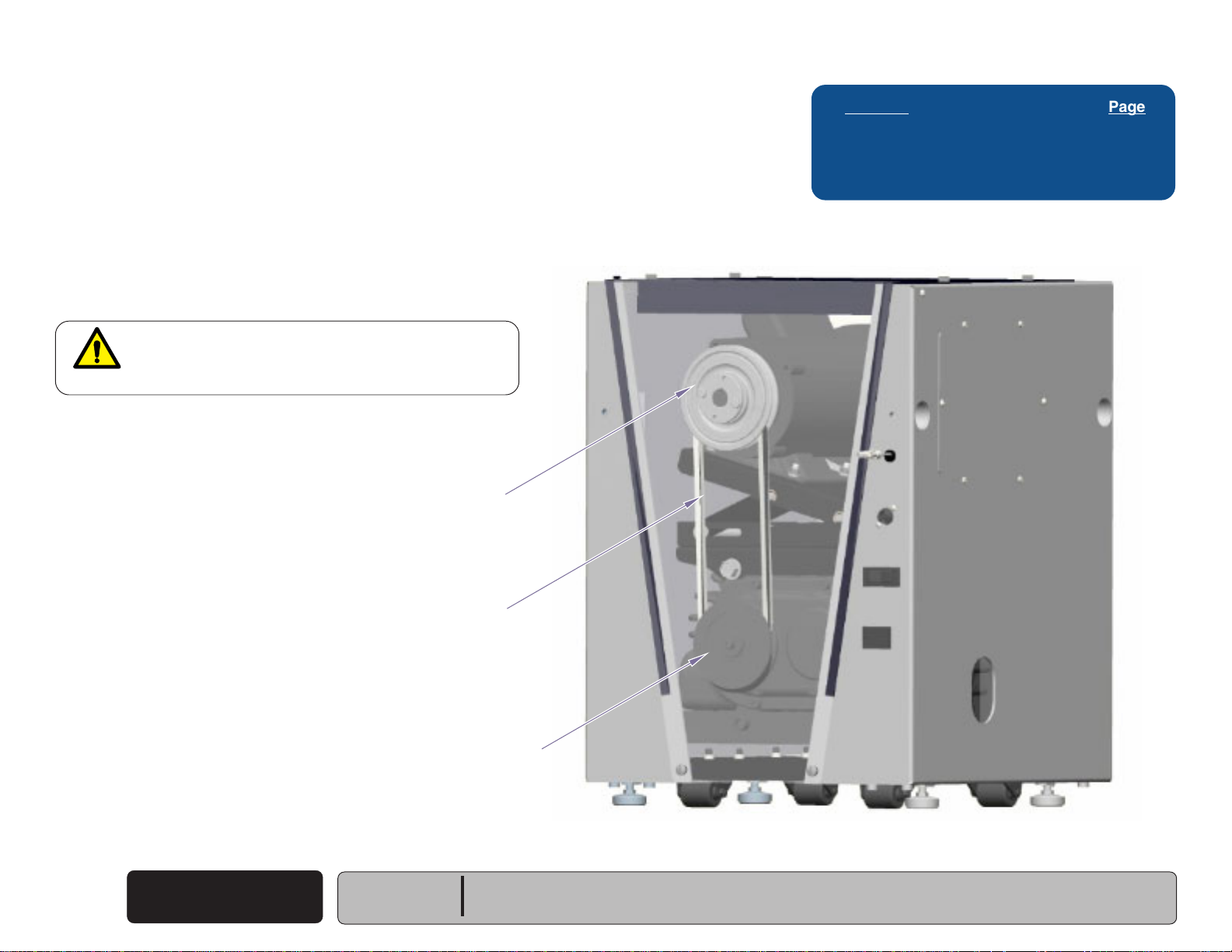
Belt
Location & Function
The Belt runs on a motor pulley system operating the pump.
Belt should never have nicks, cracks or any visible damage,
this will affect performance.
Earlier versions of the PowerVac® the belt will need adjusting
from time to time. Newer versions of the PowerVac® have an
auto tensioner.
WARNING
Motors installed after 12/08 are thermally protected
with automatic reset. Unit may start without warning.
Motor Pulley
Refer to: Page
Belt Adjustment (Tension) .................... B-3
Belt Replacement (Earlier Version) ........ B-4
Belt Replacement (New Version) ........... B-5
B-2
© Midmark Corporation 2006 SF-1873
Belt
Serial Numbers:
Rev 9/10/18
Models:
Belt
Pump Pulley
Earlier Version Shown
AA162300i
All
Page 23
Testing & Repair
10
15
20
25
Back
Go To Table Of Contents
Next
Go To Page:
Belt
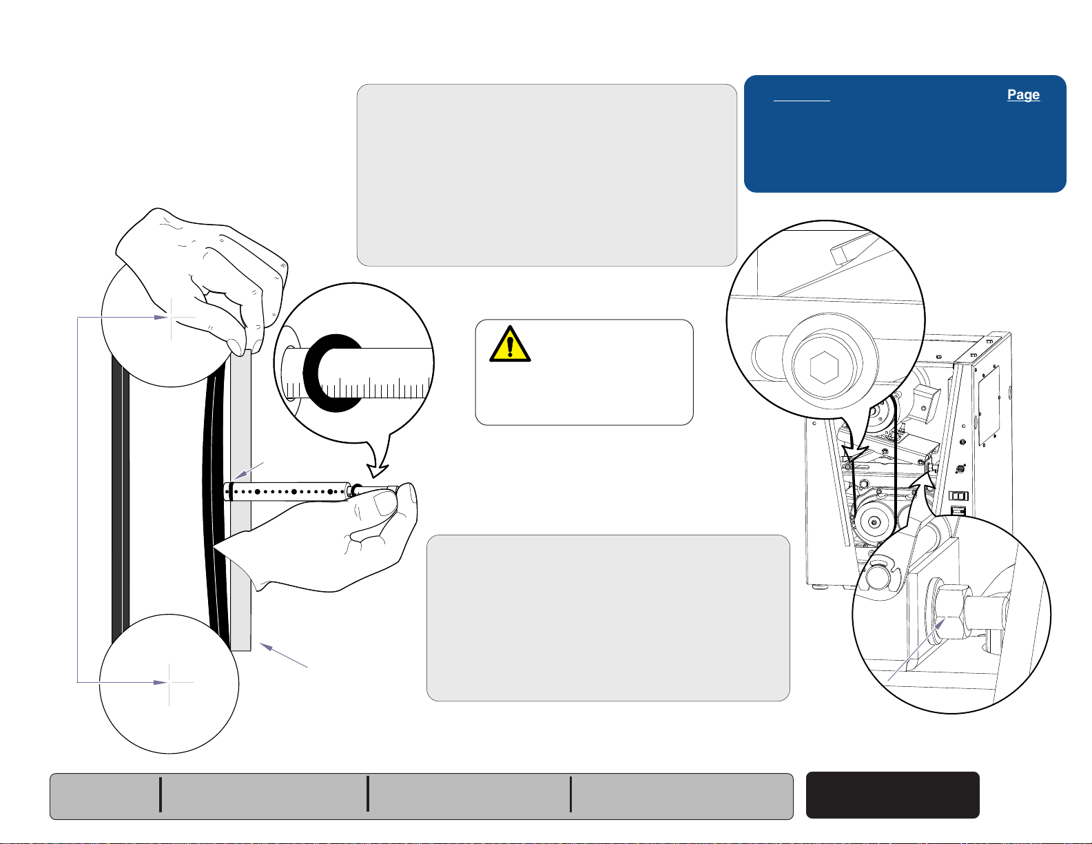
Checking and Adjusting Belt Tension
(Earlier Versions Only)
(Small End O-ring)
Large End
O-ring
12"
50
150
100
Check belt tension using belt tension checker...
A. Remove front cover. Refer to: Section C Front Cover.
B. Position o-ring on large end of tension checker to 12”
(use "Inches of Span Length" increments on checker).
C. Slide o-ring on small shaft to 0 pounds.
D. Align straight edge with belt.
E. Apply force on the plunger until o-ring on large
shaft is even with straight edge.
F. Remove the tension checker and read the defection
force the small o-ring was moved to.
Verify deflection reading is 7 lbs.
7 pounds
WARNING
Motors installed after
12/08 are thermally protected
with automatic reset. Unit may
start without warning.
15
10
25
20
30
I
f adjustment is needed...
A. Loosen Motor Mount Bolt.
B. Move adjustment nut clockwise to tighten belt.
C. Move adjustment nut counter clockwise to loosen belt
D. Use belt tension checker to recheck deflection reading.
E. Tighten motor mount bolt.
F. Replace front cover.
Refer to: Page
Belt Location and Function .................... B-2
Belt Replacement (Earlier Version) ........ B-4
Belt Replacement (New Version) ........... B-5
Front Cover ........................................... C-2
Motor Mount Bolt
ON
OFF
HOURS
AA168200i
Models:
Serial Numbers:
P3
0611P3P0000 to 0801P3P0611
V245092 to V317654
Straight Edge
If no adjustment is needed...
A. Tighten motor mount bolt.
B. Replace front cover.
0611P5P0000 to 0801P5P0240
V245092 to V317641
P5
0611P7P0000 to 0712P7P0104
V245092 to V317634
P7
Adjustment Nut
Belt
© Midmark Corporation 2006 SF-1873
Rev 9/10/18
B-3
Page 24
Testing & Repair
Back
Go To Table Of Contents
Next
Go To Page:
Belt
Replacement
(Earlier Versions Only)
Caution
The On/Off switch controls only the secondary circuit power.
The main power source must be turned off to remove all power in the control box.
WARNING
Motors installed after 12/08 are thermally protected
with automatic reset. Unit may start without warning.
Removal
Step 1: Disconnect power at on/off switch
and main power supply box.
Refer to: Page
Belt Location and Function .................... B-2
Belt Adjustment (Earlier Version) .......... B-3
Belt Replacement (New Version) ........... B-5
Front Cover ........................................... C-2
Removal
Step 2: Remove front cover.
Refer to: Section C - Front Cover
Motor Mount Bolt
Removal
Step 3: Loosen motor mount bolt
and adjustment bolt.
Removal
Step 4: Remove belt.
Installation
Step 5: Replace belt.
Installation
Step 6: Tighten adjustment bolt
and motor mount bolt.
Installation
Step 7: Set belt tension.
ON
OFF
HOURS
Refer to: Section B - Belt Adjustment
Installation
Step 8: Replace front cover.
B-4
© Midmark Corporation 2006 SF-1873
Belt
Serial Numbers:
Rev 9/10/18
Models:
Adjustment Bolt
0611P3P0000 to 0801P3P0611
V245092 to V317654
P3
AA162700i
Installation
Step 9: Connect power.
0611P5P0000 to 0801P5P0240
V245092 to V317641
P5
0611P7P0000 to 0712P7P0104
V245092 to V317634
P7
Page 25
Belt
Back
Go To Table Of Contents
Next
Go To Page:
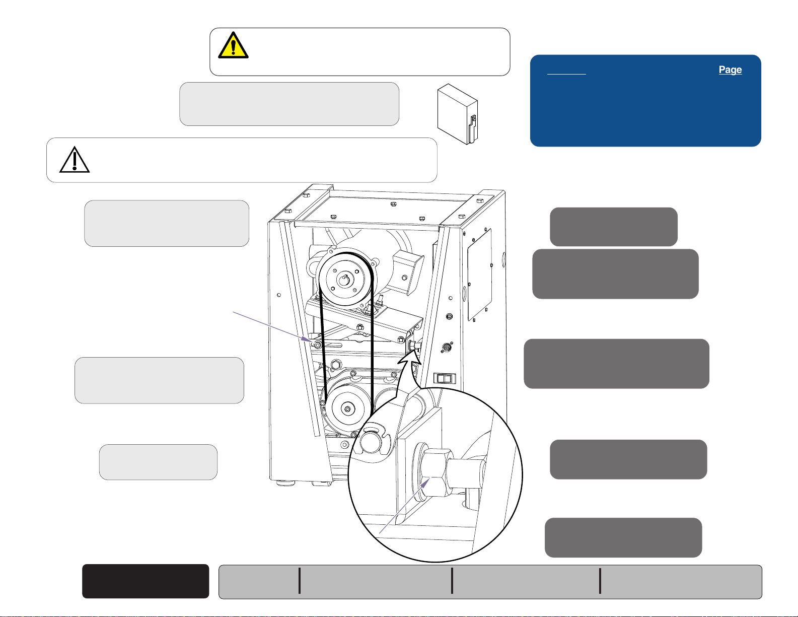
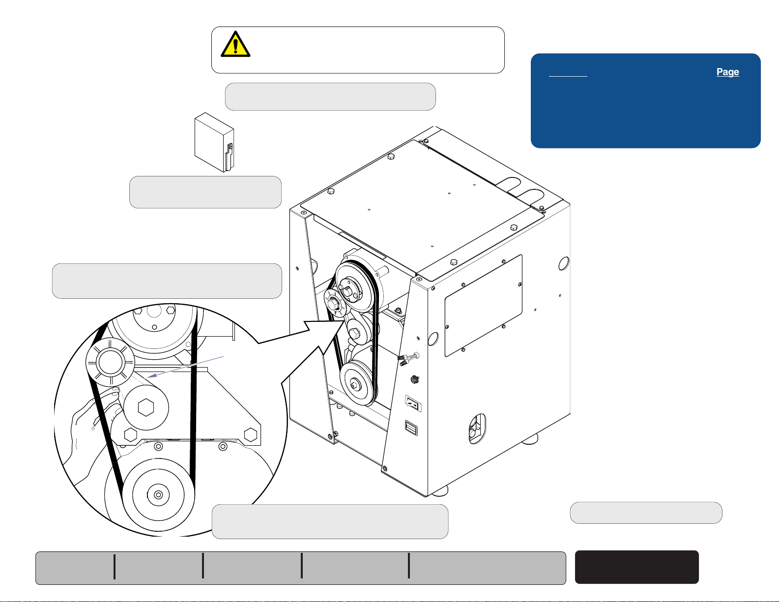
Replacement
with automatic reset. Unit may start without warning.
Step 1: Disconnect power at on/off switch
(Newer Versions Only)
Step 2: Remove front cover.
Refer to: Section C Front Cover
Step 3: Slightly push tension arm up toward the
pulley and remove belt with other hand.
WARNING
Motors installed after 12/08 are thermally protected
and main power supply box.
Testing & Repair
Refer to: Page
Belt Location and Function .................... B-2
Belt Adjustment (Earlier Version) .......... B-3
Belt Replacement (Earlier Version) ........ B-4
Front Cover ........................................... C-2
Models:
Serial Numbers:
P3
0802P3P0612 thru
Present
Tension Arm
Step 4: Slightly push tension arm up toward the
pulley and install new belt with other hand.
P5
0801P5P0241 thru
Present
P7
0712P7P0105 thru
Present
AA221600
All
V785000 thru
Present
Step 5: Replace front cover.
Belt
© Midmark Corporation 2006 SF-1873
Rev 9/10/18
B-5
Page 26
Testing & Repair
Back
Go To Table Of Contents
Next
Go To Page:
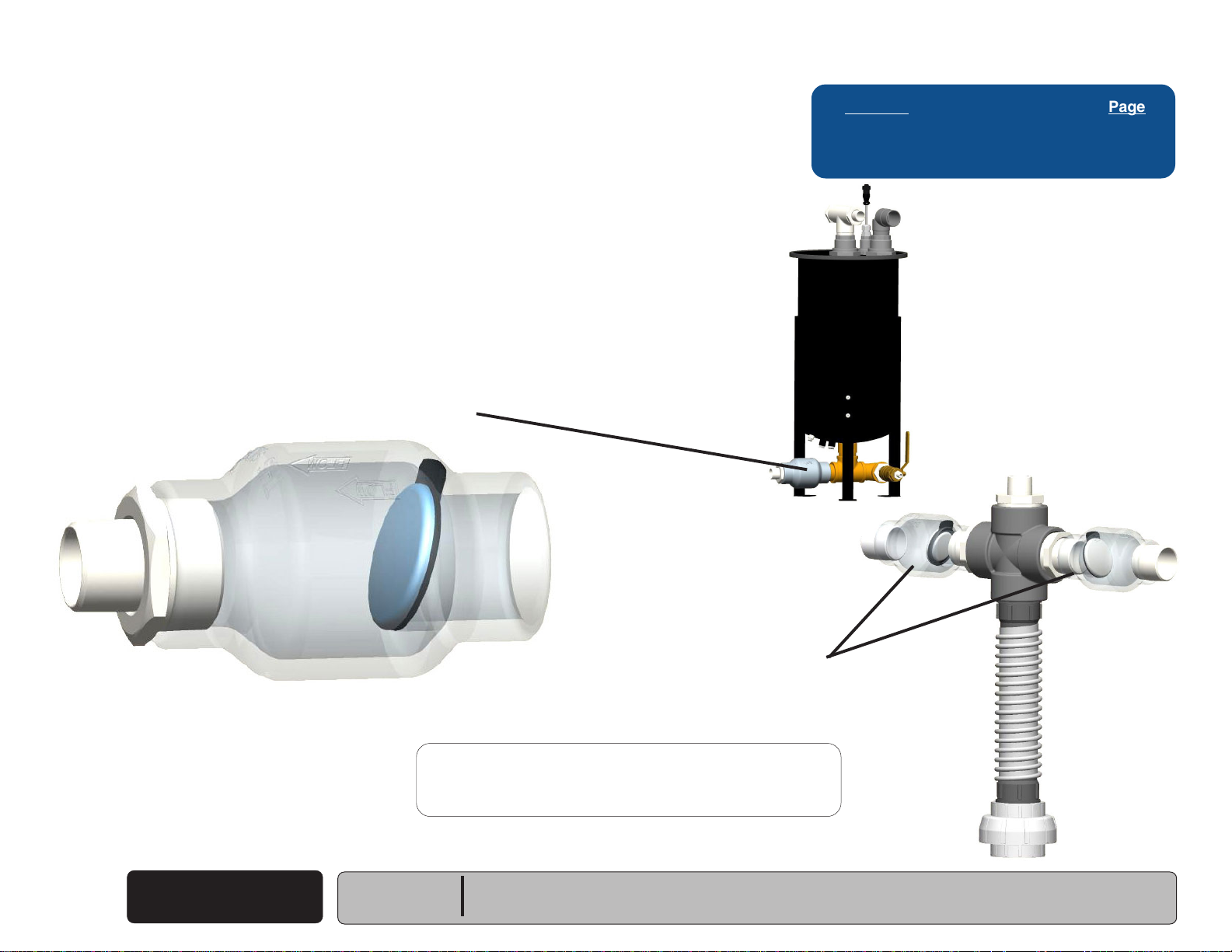
Check Valve
Location and Function
The Check Valve located in the drain allows the separator to
drain upon removal of vacuum pressure. When the pump is
not running, the valve opens, allowing liquids to drain. If the
pump is running the valve closes to keep air in the drain from
back flushing into the system.
Each vacuum pump in a multiple pump installation requires a
check valve to be installed into the intake line.
This prevents loss of suction pressure when one pump in the
system is turned off. If no check valve is present, flow will be
allowed through he "off" pump, creating a loss suction of the
rest of the system.
Vacuum Pressure keeps Valve
Closed when Pump is Running
Refer to: Page
Check Valve Test ................................. B-7
Check Valve Replacement .................... B-8
Earlier Version Shown
Located at bottom
drain on all units
B-6
© Midmark Corporation 2006 SF-1873
When Pump Stops Valve Opens
for Liquids and Solids to Drain
Check Valve
Serial Numbers:
Rev 9/10/18
Multiple Units have two additional check
valves, located in the Tee Assembly
Note: When installing check valve in horizontal position,
Models:
confirm the hinge for the flapper is on top of the valve.
All
Page 27

Testing & Repair
AA163000i
Back
Go To Table Of Contents
Next
Go To Page:
Check Valve
Testing
Equipment Room
Operatory
On / Off Switch
AA152901i
Step 2: Turn vacuum off and
ensure that water
drains from separator.
Refer to: Page
Check Valve Location and Function ...... B-6
Check Valve Replacement .................... B-8
Step 3: Turn power off.
Step 4: Allow unit to drain completely.
Step 1: Vacuum 1-2 gallons of fresh
water into system through
operatory lines.
Note: If water does not drain out, remove lid and see if valve is clogged.
Serial Numbers:
(If so flush and clean tank, if not replace valve.)
If water drains out, continue with next test on step 3.
Models:
All
Earlier Version Shown
Step 6: Turn power on and place hand over end of drain hose.
Note: If you feel suction check valve is stuck, replace check valve.
If no suction is felt then check valve is good.
© Midmark Corporation 2006 SF-1873
Step 5: Pull drain hose
Check Valve
out of drain.
Rev 9/10/18
B-7
Page 28
Testing & Repair
Back
Go To Table Of Contents
Next
Go To Page:
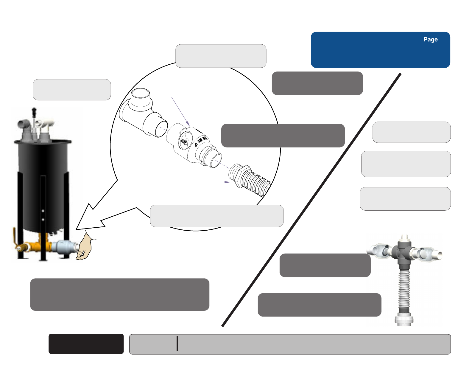
Check Valve
Replacement
Removal
Step 1: Turn power off.
All Units
Removal
Step 3: Unscrew check valve.
Check
Valve
Drain Hose
Verify criteria of valve so the
correct position is "up".
Installation
Step 5: Install drain hose to check valve.
Refer to: Page
Check Valve Location and Function ...... B-6
Check Valve Test ................................. B-7
Installation
Step 4: Install check valve.
Twin Units
Removal
Step 1: Turn power off.
Removal
Step 2: Remove drain hose
from check valve.
Removal
Step 3: Unscrew check valve.
Earlier Version Shown
Installation
Step 6: Turn power on and place hand over end of check valve.
Note: Verify you do NOT feel any suction.
B-8
© Midmark Corporation 2006 SF-1873
AA162900i
Check Valve
Serial Numbers:
Rev 9/10/18
Removal
Step 2: Remove drain hose from check valve.
Models:
All
Twin Unit Tee Assembly Check Valves
Installation
Step 4: Install check valve.
Installation
Step 5: Install drain hose to check valve.
Page 29
Testing & Repair
Back
Go To Table Of Contents
Next
Go To Page:
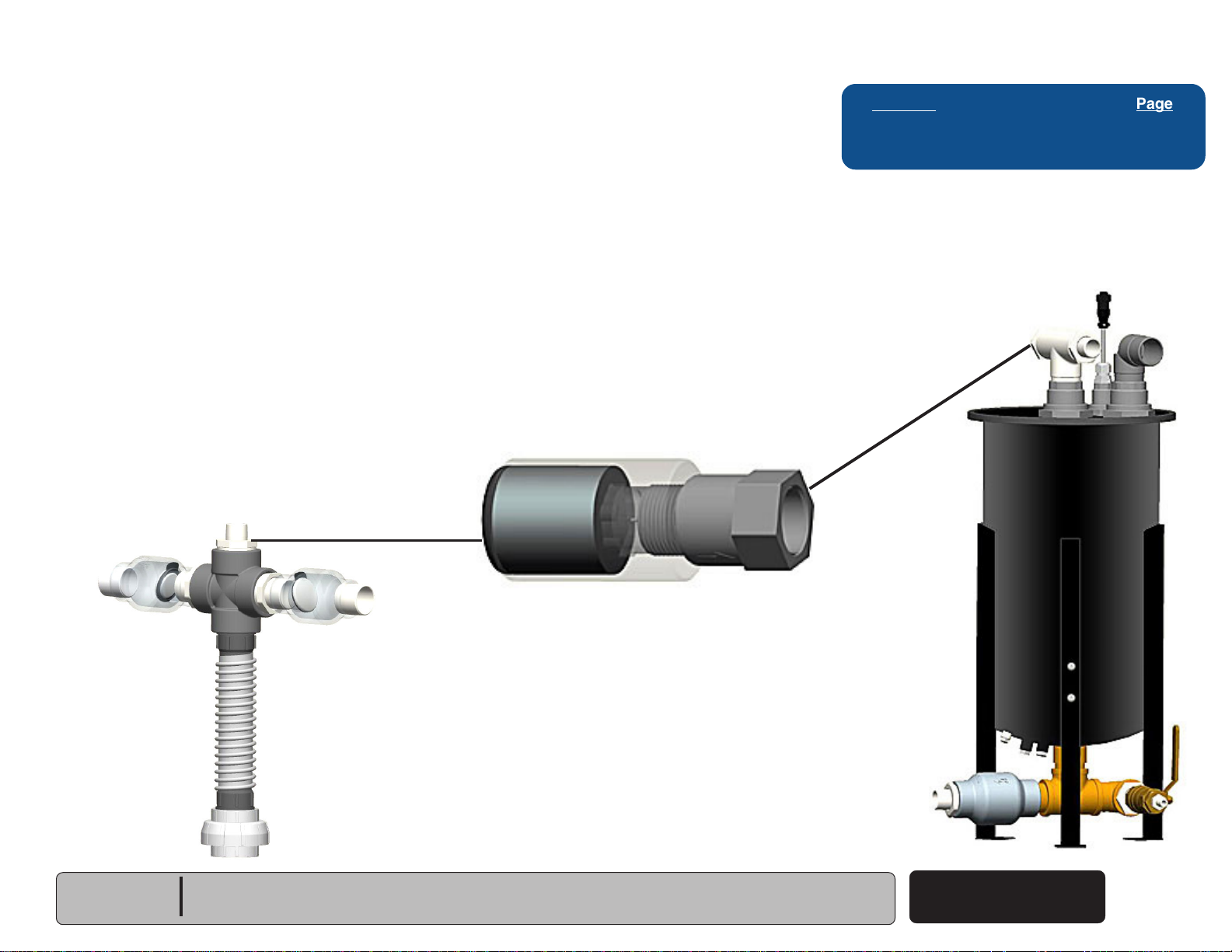
Vacuum Relief Valve
Location and Function
The Vacuum Relief Valve regulates the vacuum pressure in
the PowerVac
.
The Vacuum Relief Valve has a 1" NPT male fitting on one
side and 1" NPT female fitting on the other side.
The valve is adjustable up to 18"Hg.
Recommended range for the system vacuum is from 10" to
18"Hg. The valve is preset at the factory for 12" Hg.
The Vacuum Relief Valve is located on top of the separator
tank in the "T" Fitting on Single Models and in the center of
the mounted "T" assembly on the Twin Models.
®
Twin Unit Location
Refer to: Page
VRV Adjustment ................................... B-10
VRV Replacement ................................ B-11
Single Unit Location
Models:
Serial Numbers:
All
Earlier Version Shown
Vacuum Relief Valve
© Midmark Corporation 2006 SF-1873
Rev 9/10/18
B-9
Page 30
Testing & Repair
Back
Go To Table Of Contents
Next
Go To Page:
Vacuum Relief Valve
Adjustment
Step 1: Turn power off.
Single Unit Location
0
2
5
2
0
3
-
Step 2: Remove the filter and valve by unscrewing from tee-fitting.
Filter
Valve
5
1
0
1
5
0
Step 3: Adjust the center mounted screw inside the valve.
Twin Unit Location
Refer to: Page
VRV Location and Function................... B-9
VRV Replacement ................................ B-11
Note: Use 1/4 inch nutdriver and phillips screwdriver.
Each full clockwise turn increases the vacuum level by
approximately 2 inch Hg.
Vacuum Relief Valve
B-10
© Midmark Corporation 2006 SF-1873
AA163100i
Earlier Version Shown
Rev 9/10/18
Models:
Serial Numbers:
Step 4: Install filter and valve.
Note: Recommended Range is 10” Hg - 18 Hg.
Vacuum is preset at 12” Hg.
If reading is low check for leaks or open operatory lines.
All
Page 31

Testing & Repair
Back
Go To Table Of Contents
Next
Go To Page:
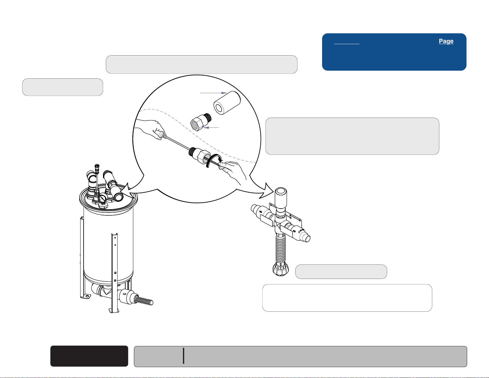
Vacuum Relief Valve
Replacement
Removal
Step 1: Turn power off.
Single Unit Location
Refer to: Page
VRV Location and Function................... B-9
VRV Adjustment ................................... B-10
Filter
Twin Unit Location
Valve
5
1
0
2
0
1
5
2
5
0
3
0
Removal
Step 2: Unscrew valve from tee-fitting.
Unscrew valve from filter.
Models:
Serial Numbers:
All
Installation
Step 3: Screw filter onto valve.
AA163200i
Earlier Version Shown
Screw valve assembly into tee-fitting.
Installation
Step 4: Turn power on.
Installation
Step 5: Perform Adjustment.
Refer to: Section B - VRV Adjustment
Vacuum Relief Valve
© Midmark Corporation 2006 SF-1873
Rev 9/10/18
B-11
Page 32

Testing & Repair
Back
Go To Table Of Contents
Next
Go To Page:
Exhaust Valve
Location and Function
The exhaust check valve provides protection for the pump. It
prevents moisture from entering the pump from the exhaust
line.
Refer to: Page
Exhaust Valve Check ........................... B-13
Exhaust Valve Replacement ................. B-14
B-12
© Midmark Corporation 2006 SF-1873
Exhaust Valve
Rev 2/08
Models:
Serial Numbers:
Earlier Version Shown
All
Page 33

Testing & Repair
Back
Go To Table Of Contents
Next
Go To Page:
Exhaust Valve
Check
Step 1: Turn power off.
Barbed Fitting
Exhaust Valve
Refer to: Page
Exhaust Valve Location and Function ... B-12
Exhaust Valve Replacement ................. B-14
Step 2: Remove exhaust hose from barbed fitting.
Remove barbed fitting.
Step 3: Remove exhaust valve from nipple.
Step 4: Shake valve and listen for movement of flap.
Note: If you are able to hear the valve flap moving, it
Models:
Serial Numbers:
is good. If valve is stuck and not moving,
remove valve and clean.
If valve will not work, replace the exhaust valve.
Refer to: Section B Replacement
All
Nipple
Earlier Version Shown
AA163400i
Exhaust Valve
© Midmark Corporation 2006 SF-1873
Rev 9/10/18
B-13
Page 34

Testing & Repair
Back
Go To Table Of Contents
Next
Go To Page:
Exhaust Valve
Replacement
Removal
Step 1: Turn power off.
Barbed Fitting
Exhaust Valve
Refer to: Page
Exhaust Valve Location and Function .. B-12
Removal
Step 2: Remove exhaust hose from barbed fitting.
Remove barbed fitting.
Installation
Step 5: Screw barbed fitting into exhaust valve.
Connect exhaust hose to barbed fitting.
Removal
Step 3: Remove exhaust valve from nipple.
Installation
Step 4: Screw new exhaust valve onto nipple.
B-14
© Midmark Corporation 2006 SF-1873
Exhaust Valve
Rev 9/10/18
Nipple
Models:
Serial Numbers:
Earlier Version Shown
All
Installation
Step 6: Turn power on.
AA163400i
Page 35

Testing & Repair
Back
Go To Table Of Contents
Next
Go To Page:
Float Assembly
Location and Function
The Float Assembly contains three Float (Reed) Switches
mounted on a bracket at different intervals.
The Reed Switch has contacts that remain open until the
liquid in the separator rises, causing the float to rise until the
magnet contacts the Reed Switch.
When the magnet contacts the Reed Switch, the open
contacts inside the reed close.
When the top float switch closes, the fan, hour meter and
vacuum pump stop running until the bottom float opens and
the cycle starts again.
The upper and lower floats interact as a latching circuit with
the internal relay to release upon drain below the bottom
float. The magnet in the float is to activate the reed switch
within the stem.
If the PowerVac
installed, it begins running when the middle float switch
closes, avoiding the vacuum pump shut-off that would occur if
the liquid level closed the top switch.
®
has a Liquid Evacuation Pump (Accessory)
Refer to: Page
Check Float .......................................... B-16
Replace Float ........................................ B-17
Reed Switch
Contacts are open
until
magnet closes it.
Magnet
Float
Earlier Versions had Three Reed Switch Floats. The Middle Float
was for the Liquid Evac Pump Option. If You Have a Liquid Evac
Pump Connected to the PowerVac you Must Replace Float With a
Three Reed Switch Float Assembly. If There is No Evac Pump
Connected to the PowerVac, You can Replace the Float With a Two
Reed Switch Float Assembly.
Models:
Serial Numbers:
All
Current Version Shown
AA2293
Float Assembly
© Midmark Corporation 2006 SF-1873
Earlier Version
Shown
Rev 9/11
B-15
Page 36

Testing & Repair
Back
Go To Table Of Contents
Next
Go To Page:
Float Assembly
Earlier Versions had Three Reed Switch Floats. The Middle Float
was for the Liquid Evac Pump Option. If You Have a Liquid Evac
Pump Connected to the PowerVac you Must Replace Float With a
Three Reed Switch Float Assembly. If There is No Evac Pump
Connected to the PowerVac, You can Replace the Float With a Two
Reed Switch Float Assembly.
Check
To check float switches...
Note: If pump is not running, unplug float from base unit. If pump doesn't start running,
test relay (Section B) if pump starts running, continue with float checks...
A) Turn power off and plug float into base unit.
B) Remove gasket on separator lid.
C) Lift lid/float assembly out of tank and lay across top of tank.
D) Turn power on.
E) Move floats to down position.
F) Raise bottom float to reed swtich, then raise top float to reed swtich. Motor should stop
after top switch is raised.
G) Move top float down first, then lay bottom float down.
Motor should not start until bottom float is down.
Note: Floats should move freely, if float does not work properly, replace the float assembly.
Refer to: Page
Float Location and Function .................. B-15
Replace Float ........................................ B-17
Rinse Separator Tank .......................... B-58
Relay Test ........................................... B-32
B-16
© Midmark Corporation 2006 SF-1873
Note:
If no water in separator, but still runs when
unplugged from vacuum base unit, float maybe stuck.
Float Assembly
Rev 9/10/18
Models:
Serial Numbers:
All
Current Version Shown
AA2336
Page 37

Float Assembly
Back
Go To Table Of Contents
Next
Go To Page:
Replacement
Removal
Step 1: Turn power off.
Unplug float cord.
Earlier Versions had Three Reed Switch Floats. The Middle
Float was for the Liquid Evac Pump Option. If You Have a
Liquid Evac Pump Connected to the PowerVac you Must
Replace Float With a Three Reed Switch Float Assembly. If
There is No Evac Pump Connected to the PowerVac, You can
Replace the Float With a Two Reed Switch Float Assembly.
Float Cord Fitting
Removal
Step 3: Lift separator lid.
Hold onto float underneath lid.
Loosen float cord fitting on top of separator.
Float will come down into your hand.
Testing & Repair
Refer to: Page
Float Location and Function .................. B-15
5
1
0
2
0
1
5
2
5
0
3
0
Installation
Step 4: Insert new float assembly up through separator lid.
Check Float .......................................... B-16
Tighten float cord fitting on top of separator.
Installation
Step 6: Plug in float cord to vacuum base unit.
Turn power on.
Models:
Serial Numbers:
All
Earlier Version
Shown
Removal
Step 2: Pull gasket down off separator lid.
Installation
Step 5: Set lid on separator.
Install gasket.
AA163700i
Float Assembly
© Midmark Corporation 2006 SF-1873
Rev 9/10/18
B-17
Page 38

Testing & Repair
Back
Go To Table Of Contents
Next
Go To Page:
Master Control Panel and Low Voltage
Location and Function
Wiring for Remote ON/OFF Switch, Master Control Panel
Low voltage (24VAC) wiring provides power for a remote ON/
OFF switch and indicator light (optional).
Refer to: Page
Master Control Panel Test ................... B-19
Low Voltage Test ................................. B-20
B-18
© Midmark Corporation 2006 SF-1873
AA163400i
Low Voltage
Earlier Version Shown
Models:
Serial Numbers:
Rev 12/10
All
Page 39

Testing & Repair
Back
Go To Table Of Contents
Next
Go To Page:
Master Control Panel
Test
Step 1: Disconnect power at on/off switch
and main power supply box.
Caution
When testing components
with power on use care to
prevent electrical shock.
Step 2: Bypass the remote switch to verify it is not defective.
Disconnect the Red and Blue wires from the remote switch.
Connect the Blue and Red wires together.
Refer to: Page
Location and Function .......................... B-18
Low Voltage Test ................................. B-20
Models:
Serial Numbers:
Step 3: Connect power to the PowerVac
Turn the On/Off switch On.
Note: If the fan, hour meter and pump start running
then replace the remote switch.
®
All
Earlier Version Shown
© Midmark Corporation 2006 SF-1873
Low Voltage
Rev 9/10/18
B-19
Page 40

Testing & Repair
Transformer
Contactor
Back
Go To Table Of Contents
Next
Go To Page:
Low Voltage
Test
Step 1: Turn power off.
Step 2: Remove electrical cover.
Refer to: Section C Access Procedures
Caution
When testing components
with power on use care to
prevent electrical shock.
Refer to: Page
Location and Function .......................... B-18
Master Control Panel Testing .............. B-19
Access Procedrues .............................. C-1
Step 3: Set meter to V.
~
Step 4: Turn power on.
Step 5: Place probes on red low voltage wire on contactor
and yellow wire coming from transformer.
Note:
5
1
0
2
0
1
5
2
5
0
3
-
0
Verify voltage is 24 VAC.
B-20
© Midmark Corporation 2006 SF-1873
Low Voltage
Rev 9/10/18
AA2335
Models:
Serial Numbers:
All
Page 41

Testing & Repair
Back
Go To Table Of Contents
Next
Go To Page:
Door Limit Switch &
PowerVac® Circuit Breaker (ON/OFF Switch)
Location & Function
With facility power (230 VAC) supplied to the system....
The transformer continuously supplies 24 VAC to the
normally-open door limit switch.
With the front access cover in place...
The plastic bumper on the top right side of the access cover,
trips the door limit switch causing it to close.
When the limit switch is closed, 24 VAC flows thru the switch
to the PowerVac® circuit breaker
circuit breaker switch ON, current is supplied to the remote
wall switch
Note: If the facility does not have a remote wall switch,
(if applicable)
the PowerVac
switch for the system.
.
®
circuit breaker serves as the ON/OFF
(ON / OFF Switch)
. With the
Refer to: Page
Door Limit Switch Testing .................... B-22
Circuit Breaker (On/Off) Testing .......... B-23
Door Limit Switch Replacement ........... B-24
Circuit Breaker Replacement (On/Off) B-25
When the front access cover is removed...
The door limit switch opens and stops current flow to the
PowerVac® circuit breaker. This is a safety feature that
prevents the system from operating with the cover removed.
Models:
Serial Numbers:
All
Earlier Version Shown
Door Limit Switch
On/Off Switch
© Midmark Corporation 2006 SF-1873
Rev 2/08
B-21
Page 42

Testing & Repair
Back
Go To Table Of Contents
Next
Go To Page:
Door Limit Switch
Step 1: Turn power off.
Testing
During this step, the motor belt and pulley may spin with front cover off.
Stay clear and keep everything out of the vacuum base!
Step 3: Turn power on and depress activation button with a screwdriver.
Note: If motor starts up, quickly take pressure off switch.
Plastic bumper may be obstructed or damaged.
Check plastic bumper on door for damage.
If it is damaged, switch it with plastic bumper on opposite side of door
until a replacement can be ordered.
If motor doesn't start, continue with step 4.
Caution
Step 2: Remove front cover.
Refer to: Section C Front Cover.
Refer to: Page
Door Limit / Circuit Breaker Function .. B-21
Circuit Breaker (On/Off) Testing .......... B-23
Door Limit Switch Replacement ........... B-24
Circuit Breaker Replacement (On/Off) B-25
Section C Front Cover ......................... C-2
Caution
When testing components
with power on use care to
Mounting Screw
prevent electrical shock.
Step 5: Remove mounting screw for door limit switch.
Disconnect electrical leads.
Step 4: Turn power off.
C
O
M
NO
N
C
AA164100i
With switch 'untripped'...
OL
less than 5
ΩΩ
Ω
ΩΩ
Door Limit Switch &
B-22
© Midmark Corporation 2006 SF-1873
ON
OFF
HOURS
AA164000i
gnidaeRreteMsutatSnoitcAderiuqeR
Limit switch - OK
Circuit Breaker
Rev 9/10/18
Replace switch
Models:
Serial Numbers:
Activation
Button
Caution
Door limit switch is a safety device.
If switch is not working, do not bypass.
Warranty will be void if switch is bypassed.
If both tests fail, it must be replaced!
All
Limit Switch Test
Step 6: Test continuity. Set meter to
Place meter probes on
Note: Check switch 'tripped' and 'untripped'.
Step 7: Install front cover.
With switch 'tripped'...
gnidaeRreteMsutatSnoitcAderiuqeR
OL
less than 5
ΩΩ
Ω
ΩΩ
Ω.Ω.
Ω.
Ω.Ω.
COM and NO
Replace switch
Limit switch - OK
terminals.
Page 43

Testing & Repair
Back
Go To Table Of Contents
Next
Go To Page:
Circuit Breaker (ON/OFF Switch)
Testing
Step 1: Turn power off.
Step 2: Remove front cover.
Refer to: Section C Front Cover.
Caution
When testing components
with power on use care to
prevent electrical shock.
Circuit Breaker Test
Step 3: Test continuity. Set meter to
Disconnect leads from switch terminals.
Place meter probes on
Note: Check switch 'tripped' and 'untripped'.
COM and NO
Ω.Ω.
Ω.
Ω.Ω.
Refer to: Page
Door Limit / Circuit Breaker Function .... B-19
Door Limit Switch Testing ..................... B-20
Door Limit Switch Replacement ............ B-22
Circuit Breaker Replacement (On/Off) .. B-23
Front Cover .......................................... C-2
terminals.
OL
less than 5
Models:
Serial Numbers:
gnidaeRreteMsutatSnoitcAderiuqeR
Circuit Breaker is Good
ΩΩ
Ω
ΩΩ
Replace Circuit Breaker
All
AA165501i
Step 4: Connect switch leads.
With switch 'tripped'...
gnidaeRreteMsutatSnoitcAderiuqeR
OL
less than 5
ΩΩ
Ω
ΩΩ
Door Limit Switch &
Circuit Breaker
© Midmark Corporation 2006 SF-1873
Install front cover.
Replace Circuit Breaker
Circuit Breaker is Good
Rev 9/10/18
B-23
Page 44

Testing & Repair
Back
Go To Table Of Contents
Next
Go To Page:
Door Limit Switch
Replacement
Removal
Step 1: Disconnect power at on/off switch
and main power supply box.
Removal
Step 2: Remove front cover.
Refer to: Section C Front Cover
Caution
The On/Off switch controls only the secondary circuit power.
The main power source must be turned off to remove all power in the control box.
Vacuum system must not have power when front cover is off base unit.
Plunger
Mounting Screw
WARNING
Motors installed after
12/08 are thermally protected
with automatic reset. Unit may
start without warning.
Refer to: Page
Door Limit / Circuit Breaker Function .. B-21
Door Limit / Circuit Breaker Testing .... B-22
Circuit Breaker (On/Off) Testing .......... B-23
Circuit Breaker Replacement (On/Off) B-25
Front Cover .......................................... C-2
Removal
Step 3: Disconnect wires from limit switch.
Mounting Screw
Installation
Step 6: Connect wiring to limit switch.
Door Limit Switch &
B-24
© Midmark Corporation 2006 SF-1873
Circuit Breaker
ON
OFF
HOURS
Rev 9/10/18
AA165700i
Models:
Serial Numbers:
Removal
Step 4: Remove mounting screw and pull out limit switch and bracket.
Remove switch from bracket.
Installation
Step 5: Align limit switch with hole in side panel and
plunger away from mounting screws.
Install mounting screw as shown.
Installation
Step 7: Install front cover.
Installation
Step 8: Turn power source on.
All
Rev 1/09
Page 45

Testing & Repair
Back
Go To Table Of Contents
Next
Go To Page:
Circuit Breaker (ON/OFF Switch)
Replacement
Removal
Step 1: Disconnect power at on/off switch
and main power supply box.
Removal
Step 2: Remove front cover.
Refer to: Section C Front Cover
Refer to: Page
Door Limit / Circuit Breaker Function .... B-19
Door Limit Switch Test .......................... B-20
Circuit Breaker (On/Off) Testing ........... B-21
Door Limit Switch Replacement ............ B-22
Front Cover .......................................... C-2
Removal
Step 4: Push in on both side of breaker and push forward to pull out of panel.
Installation
Step 5: Push in on both sides of breaker.
Push breaker into panel and release
sides to snap it in to place.
Removal
Step 3: Disconnect wires from back of breaker.
Models:
Serial Numbers:
All
Installation
Step 6: Install front cover and restore power.
AA165600i
Door Limit Switch &
Circuit Breaker
© Midmark Corporation 2006 SF-1873
Rev 9/10/18
B-25
Page 46

Testing & Repair
Back
Go To Table Of Contents
Next
Go To Page:
Contactor
Location and Function
When the PowerVac® is turned on either by the remote wall
switch or vacuum unit on/off switch, the Contactor is energized. It sends current to the fan, hour meter and pump,
turning them on.
Earlier Version
Refer to: Page
Contactor Testing ................................. B-27
Current Version
B-26
© Midmark Corporation 2006 SF-1873
Contactor
Earlier Version Shown
Models:
Serial Numbers:
Rev 3/14/19
All
Page 47

Contactor
Back
Go To Table Of Contents
Next
Go To Page:
Test
Step 1: Turn power off.
Caution
When testing components
with power on use care to
prevent electrical shock.
Testing & Repair
Refer to: Page
Contactor Location and Function ......... B-26
Electrical Cover .................................... C-4
Step 3: Turn power on.
Step 2: Remove electrical cover.
Refer to Section C: Electrical Cover.
Step 5: Check voltage across contactor.
• Set meter to V.
• Place meter probes on top red wire and
bottom black wire.
Note: Verify reading is 24 volts.
AA163900
Step 4: Check high voltage on contactor.
• Set meter to V.
• Place meter probes on front, left side red
and black wires.
Note: Verify reading is line volts.
Step 6: Insert screwdriver to start manually.
Note: if system starts, replace contactor.
Step 7: Install electrical cover.
Note:
Line Voltage shoud be 208 - 230 VAC with circuit loaded
(equipment running)
gnidaeRreteMsutatSnoitcAderiuqeR
Models:
Serial Numbers:
All
Line Volts
(Left side check)
24 Volts
(Top and Bottom check)
)
Contactor OK
Contactor OK
Contactor
© Midmark Corporation 2006 SF-1873
Rev 9/10/18
B-27
Page 48

Testing & Repair
Back
Go To Table Of Contents
Next
Go To Page:
Fuse
Location and Function
The fuse limits the electrical current from the transformer to
the contactor. It interrupts the electrical currents in the case
of an overload.
Only replace fuse with 1/8 amp, 250 volt, Slo Blo, fuse.
Refer to: Page
Fuse Testing ........................................ B-29
Fuse Replacement ............................... B-30
B-28
© Midmark Corporation 2006 SF-1873
Fuse
Earlier Version Shown
Models:
Serial Numbers:
All
Page 49

Testing & Repair
AA164301i
Back
Go To Table Of Contents
Next
Go To Page:
Fuse
Testing
Step 1: Turn power off.
Step 2: Remove electrical cover.
Refer to Section C: Electrical Cover.
Refer to: Page
Fuse Location and Function ................. B-28
Fuse Replacement ............................... B-30
Electrical cover ..................................... C-4
Step 3: Remove terminal leads.
Test continuity. Set meter to
Place meter probes on both fuse terminals.
Ω.Ω.
Ω.
Ω.Ω.
OL - off line
Burnt or Broken
Continuity checks ok
Visually looks ok
Models:
Serial Numbers:
gnidaeRreteMsutatSnoitcAderiuqeR
All
Replace Fuse
Fuse is Good
Step 4: Visually check fuse to see if it is burnt or broken.
Step 5: Install electrical cover.
Fuse
© Midmark Corporation 2006 SF-1873
Rev 9/10/18
B-29
Page 50

Testing & Repair
Back
Go To Table Of Contents
Next
Go To Page:
Fuse
Replacement
Removal
Step 1: Turn power off.
Removal
Step 3: Pull fuse out.
Refer to: Page
Fuse Location and Function ................. B-28
Fuse Testing ........................................ B-29
Electrical cover ..................................... C-4
Removal
Step 2: Remove electrical cover.
Refer to: Section C - Electrical Cover
B-30
© Midmark Corporation 2006 SF-1873
Fuse
Serial Numbers:
Rev 9/10/18
Models:
AA164400i
Installation
Step 4: Insert new fuse and perform continuity test.
Refer to: Section B Fuse Test
Installation
Step 5: Install electrical cover.
All
Page 51

Testing & Repair
Back
Go To Table Of Contents
Next
Go To Page:
Relay
Location and Function
Power is disconnected from the Contactor when the relay is
energized by the top float switch closing (water level reaching top float switch).
The PowerVac® electrical system can be checked by pressing
the test button on the side. If the unit shuts down, the rest of
the electrical system is functioning properly.
Earlier Version
Refer to: Page
Relay Testing ....................................... B-32
Relay Replacement .............................. B-33
Current Version
Models:
Serial Numbers:
Earlier Version Shown
All
Relay
© Midmark Corporation 2006 SF-1873
B-31
Rev 3/14/19
Page 52

Testing & Repair
Back
Go To Table Of Contents
Next
Go To Page:
Relay
Note:
If the motor is not shutting off when the top collection tank
float is actuated, check relay by pressing the Test Button.
If the motor is not running, By-Pass Relay to check operation.
Test
Relay Test Button. (Motor not off with top float actuated)
Step 1: Turn power off.
Step 2: Remove electrical cover.
Cover.
Refer to Section C: Electrical
Step 3: Verify all wire connections are secure to relay.
Step 4: Turn power on.
Step 5: Push in test button on side of relay, if unit shuts down, relay
is bad.
Note:
I
f the unit does not shut down when top float is activated,
but shuts off properly when the relay test button is pressed, the
coil in the relay is likely defective (barring any other wiring issues). The light on the relay is only an indicator that there is
power to the coil.
Caution
When testing components
with power on use care to
prevent electrical shock.
24V from
transformer
By-Pass Relay Test
Step 1: Turn power off.
Step 2: Disconnect blue wire from Relay(2) and connect
Step 3: Turn power on.
Refer to: Page
Relay Location and Function ................. B-30
Relay Replacement ............................... B-32
Electrical cover ..................................... C-4
Disconnect
WH
BK
BL
Coil
CR1 (Float Switch) RELAY
7
Coil
8
WH
Coil
Contacts Open
6
5
Contacts Closed
Reconnect Wire
4
3
2
1
RD
AA168500-1i
BL
wire to left side of Relay(6) which has a direct
feed from the transformer.
Wire
B-32
© Midmark Corporation 2006 SF-1873
Relay
AA164500i
Serial Numbers:
Rev 9/10/18
Test Button
Models:
All
Test Results
Unit Starts when Relay
Is By-Passed
With the Top Collection Tank Float
Actuated, Unit Only Shuts OFF When
Relay Test Button is Depressed
Status Required Action
Replace Relay
Replace Relay
Page 53

Testing & Repair
Back
Go To Table Of Contents
Next
Go To Page:
Relay
Replacement
Removal
Step 1: Disconnect power at on/off switch
and main power supply box.
Removal
Step 2: Remove electrical cover.
Refer to Section C: Electrical Cover.
Earlier Version
Refer to: Page
Relay Location and Function ................. B-30
Relay Testing ........................................ B-31
Electrical cover ..................................... C-4
Current Version
Removal
Step 3: Unplug relay from base.
Models:
Serial Numbers:
All
Installation
Step 4: Plug in new relay. Restore power.
Push in test button to verify unit shuts down after turning power on.
Installation
Step 5: Install electrical cover.
Relay
© Midmark Corporation 2006 SF-1873
Rev 3/14/19
B-33
Page 54

Testing & Repair
Back
Go To Table Of Contents
Next
Go To Page:
Transformer
Location and Function
The Transformer steps the 230 VAC supply down to 24 VAC.
This is the voltage at the relay and terminal block.
Refer to: Page
Transformer Testing............................. B-35
Transformer Replacement ................... B-36
B-34
© Midmark Corporation 2006 SF-1873
Earlier Version Shown
Transformer
Models:
Serial Numbers:
All
Page 55

Testing & Repair
Back
Go To Table Of Contents
Next
Go To Page:
Transformer
Testing
Step 1: Turn power off.
Step 2: Remove electrical cover.
Refer to Section C: Electrical Cover.
Step 4: Feel transformer to verify it is not hot.
If it is hot, allow it to cool off.
Note: Transformer has a internal non-resetting overload fuse.
If transformer is hot to touch, allow to cool before testing. If
it's hot check ambient operating temp and input / output
voltage. Verify abient room temperature doesn't exceed 104°
Fahrenheit (37 Celsius).
Step 5: Turn power on.
Caution
When testing components
with power on use care to
prevent electrical shock.
Refer to: Page
Transformer Location and Function ..... B-34
Transformer Replacement ................... B-36
Electrical cover ..................................... C-4
Step 3: Verify all wire connections are secure to
transformer, relay and terminal block.
AA164900i
Step 6: Check low voltage on transformer connections.
• Set meter to V.
• Place meter probe on yellow wire connection from transformer to terminal block.
• Place meter probe on blue wire connection from transformer to relay.
Note: Verify reading is 24 volts (-2 / +4).
Exceeds
24 Volts -2 / +4
Within
24 Volts -2 / +4
Models:
Serial Numbers:
gnidaeRreteMsutatSnoitcAderiuqeR
All
Replace Transformer
Transformer is Good
Step 7: Install electrical cover.
© Midmark Corporation 2006 SF-1873
Transformer
Rev 9/10/18
B-35
Page 56

Testing & Repair
Back
Go To Table Of Contents
Next
Go To Page:
Transformer
Replacement
Removal
Step 1: Disconnect power at on/off switch
and main power supply box.
Removal
Step 2: Remove electrical cover.
Refer to Section C: Electrical Cover.
Removal
Step 3: Disconnect all transformer wiring.
Refer to: Page
Transformer Location and Function ....... B-33
Transformer Testing............................. B-35
Electrical cover ..................................... C-4
Installation
Step 6: Connected wiring.
Removal
Step 4: Unscrew transformer from electrical box.
B-36
© Midmark Corporation 2006 SF-1873
Transformer
Rev 9/10/18
Models:
Serial Numbers:
Installation
Step 5: Screw new transformer into electrical box.
All
AA165000i
Installation
Step 7: Install electrical cover.
Resotre power.
Page 57

Testing & Repair
Back
Go To Table Of Contents
Next
Go To Page:
Fans
Location and Function
Depending on the version of PowerVac® you have, single or dual
fans are used to cool the base unit by circulating air whenever
the pump is running. The ON/OFF function of the fans are
controlled by the CR1 relay.
With the CR1 Relay OPEN (light OFF), 230 VAC is supplied to
the fan(s) thru Contactor "C". When voltage is applied to the
fan(s), the fan(s) is energized.+
With the CR1 Relay CLOSED (light ON) there is no current flow
to the Contactor "C" or to the fan(s). The fan(s) do not run.
Fans in the earlier version of PowerVac® models are located on a
mounting bracket above the pump. Dual fans on newer
versions are located on the back cover and are wired in parallel
with the same electrical box connections as the single fan unit.
Refer to: Page
Fan Testing .......................................... B-38
Fan Replacement (Earlier Version) ..... B-39
Fan Replacement (New Version) ......... B-40
Models:
Serial Numbers:
All
Earlier Version
New Version
Fan
© Midmark Corporation 2006 SF-1873
Rev 2/08
B-37
Page 58

Testing & Repair
Meter Reading Required Action
230 Volts Replace Fan
<230 Volts Replace Harness
Back
Go To Table Of Contents
Next
Go To Page:
Fan
Step 3: Set meter to V.
Testing (if fan is not running)
Step 1: Disconnect power at on/off
switch and main power supply box.
Step 2: Newer Versions - Remove back cover.
Refer to Section C: Back Cover.
Step 4: Unplug harness from fan. Turn power on at base unit and supply power box.
Note: Verify pump is running. If pump is not running, Check for 230 volts where fan(s) connect to contactor.
Caution
When testing components
with power on use care to
prevent electrical shock.
Refer to: Page
Fan Location and Function ................... B-37
Fan Replacement (Earlier Version) ..... B-39
Fan Replacement (New Version) ......... B-40
Electrical Cover ................................... C-4
Back Cover ........................................... C-5
Step 5: Verify fan harness connection to contactor is tight and not loose.
Check voltage in fan harness.
Note: Verify reading is 230 volts.
Fan
B-38
© Midmark Corporation 2006 SF-1873
Rev 9/10/18
Models:
Serial Numbers:
Fan Plug Connection
AA164700i
All
Page 59

Testing & Repair
Back
Go To Table Of Contents
Next
Go To Page:
Fan
Replacement (Earlier Versions Only)
Removal
Step 1: Disconnect power at on/off switch
and main power supply box.
Removal
Step 3: Disconnect plug wires from fan.
Fan Mounting Bracket
Refer to: Page
Fan Location and Function ................... B-37
Fan Testing .......................................... B-38
Fan Replacement (New Version) ........... B-39
Electrical cover ..................................... C-4
Exhaust Valve Assembly
Removal
Step 2: • Remove drain hose.
• Unscrew exhaust valve assembly.
Installation
Step 6: • Screw fan guard through front of mounting bracket and into new fan.
• Screw mounting bracket into vac base unit.
Removal
Step 4: Unscrew fan mounting bracket from vac base unit.
Removal
Step 5: • Unscrew fan guard from mounting bracket.
Models:
Serial Numbers:
• Remove fan from back of mounting bracket.
0611P3P0000 to 0801P3P0611
V245092 to V784999
P3
0611P5P0000 to 0801P5P0240
V245092 to V784999
P5
Installation
Step 7: • Connect plug wires to fan.
P7
0611P7P0000 to 0712P7P0104
V245092 to V784999
• Install exhaust valve assembly.
AA164800i
Fan
© Midmark Corporation 2006 SF-1873
Rev 9/10/18
B-39
Page 60

Testing & Repair
Back
Go To Table Of Contents
Next
Go To Page:
Fans
Step 1: Disconnect power at on/off switch
Replacement
Removal
Step 2: Remove back cover.
Refer to: Section C Back Cover
Removal
and main power supply box.
Refer to: Page
Fan Location and Function ................... B-37
Fan Testing .......................................... B-38
Fan Replacement (Earlier Version) ..... B-39
Back Cover ........................................... C-5
Removal
Step 4: Unscrew fan units from inside of cover.
Installation
Step 5: Screw fan units onto inside
of cover.
Removal
Step 3: Unscrew fan guards from
outside of cover.
Installation
Step 6: Screw fan guards onto
B-40
© Midmark Corporation 2006 SF-1873
outside of cover.
P3
0802P3P0612 to Present
Fan
Rev 9/10/18
Models:
Serial Numbers:
P5
0801P5P0241 to Present
AA220400
P7
0712P7P0105 to Present
Installation
Step 7: Replace back cover.
Restore power.
All
V785000 thru
Present
Page 61

Testing & Repair
Back
Go To Table Of Contents
Next
Go To Page:
Gauge
Location and Function
The Vacuum Gauge has a 1/4" NPT fitting and a range from
0 to -30 In./Hg. graduated in increments of 0.5 In./Hg.
Recommended range for the system vacuum is 10"Hg to
18"Hg. The system is preset at the factory for 12"Hg.
Refer to: Page
Gauge Replacement ............................. B-42
Models:
Serial Numbers:
All
Earlier Version Shown
Gauge
© Midmark Corporation 2006 SF-1873
Rev 9/10
B-41
Page 62

Testing & Repair
Back
Go To Table Of Contents
Next
Go To Page:
Gauge
Replacement
Removal
Step 1: Turn power off.
Removal
Step 2: Unscrew gauge from fitting.
Refer to: Page
Gauge Location and Function ............... B-41
Installation
Step 3: Apply teflon tape to threads on new gauge.
Installation
Step 4: Screw new gauge into fitting.
B-42
© Midmark Corporation 2006 SF-1873
Gauge
Serial Numbers:
Rev 9/10/18
AA165400i
Earlier Version Shown
Models:
All
Page 63

Testing & Repair
Back
Go To Table Of Contents
Next
Go To Page:
Motor
Location & Function
The electric motor is located on an adjustable motor mount
and is easily accessible. A thermal overload switch is located
on the side of the motor (Red Button). The belt driven motor
is a 2 HP single phase, 208-230 volt motor.
Earlier Version Shown
Refer to: Page
Motor Checks...................................... B-44
Belt ....................................................... B-2
Front Cover ........................................... C-2
Earlier Versions
Motor Replacement (Removal) ........... B-45
Motor Replacement (Installation) ......... B-46
Motor Mount Adjustment ...................... B-47
Newer Versions
Motor Replacement (Removal) ........... B-48
Motor Replacement (Installation) ......... B-49
Earlier Version Shown
Models:
Serial Numbers:
WARNING
Motors installed after 12/08 are thermally protected
with automatic reset. Unit may start without warning.
All
Motor
© Midmark Corporation 2006 SF-1873
Rev 9/10/18
B-43
Page 64

Testing & Repair
Back
Go To Table Of Contents
Next
Go To Page:
Caution
Motor
Check
Step 1: Turn off power at
on/off switch and
power supply box.
Wire Connections
Step 3: Remove electrical cover off motor.
Verify all wires are connected.
The On/Off switch controls only the secondary circuit power.
The main power source must be turned off to remove all power in the control box.
Capacitors must be discharged before touching to remove.
Step 2: Remove front cover.
Remove belt and verify motor
pulley spins freely. If it doesn't,
replace motor, bearing is out in
motor. If it does, continue checks.
Refer to: Section C - Front Cover
Capacitor
Step 5: Replace Capacitor.
• Access start and run capacitor by
removing top cover and capacitor
covers off motor.
• Discharge capacitors by touching two
screwdrivers to two contacts on a
capacitor and to each other.
Refer to: Section C Top Cover
Refer to: Page
Motor Location and Function ................ B-42
Belt ....................................................... B-2
Front Cover ........................................... C-2
Top Cover ............................................. C-3
Earlier Versions
Motor Replacement (Removal) ............. B-44
Motor Replacement (Installation) ........... B-45
Motor Mount Adjustment ....................... B-46
Newer Versions
Motor Replacement (Removal) ............. B-47
Motor Replacement (Installation) ........... B-48
Discharge Capacitor
Run Capacitor
Reset Thermal Overload - Earlier Version Only
Step 4: • Allow motor to cool.
• Press thermal overload button.
• Install front cover.
• Connect Power.
Note: Manual reset button on earlier versions only, current
versions have automatic reset.
"O" or "Open" Reading
Start Low and
Increases
B-44
© Midmark Corporation 2006 SF-1873
AA166000i
gnidaeRreteMsutatSnoitcAderiuqeR
Earlier Version Shown
Thermal Overload Button
Replace Capacitor
Motor
Serial Numbers:
Rev 9/10/18
Electrical Cover
Capacitor - OK
Models:
Step 6: Set meter to highest
WARNING
Motors installed
after 12/08 are thermally
protected with automatic
reset. Unit may start
without warning.
All
Start
Capacitor
Ω Ω
Ω reading
Ω Ω
..
.
..
Step 7: Place meter
probes on
capacitor
connectors.
Page 65

Motor (Removal)
Back
Go To Table Of Contents
Next
Go To Page:
Replacement (Earlier Versions Only)
Removal
Step 1: Disconnect power at on/off switch
and main power supply box
Removal
Step 2: Remove front cover.
Refer to: Section C - Front Cover
Sheave
Caution
The On/Off switch controls only the secondary circuit power.
The main power source must be turned off to remove all
power in the control box.
Removal
Step 5: Measure end of shaft to
face of top pulley.
Write dimension down.
Removal
Step 6: • Unscrew removal bolts
from hub through holes.
• Screw bolts into threaded
removal holes alternately
to pull sheave off tapered hub.
Testing & Repair
Refer to: Page
Motor Location and Function ................ B-42
Motor Checks ....................................... B-43
Motor Replacement (Installation) ........... B-45
Belt ............................................... B-2
Front Cover .......................................... C-2
Measure
Removal
Step 3: Loosen motor mount bolt
and adjustment bolt.
Removal
Step 4: Remove belt.
Models:
Serial Numbers:
0611P3P0000 to 0801P3P0611
V245092 thru V784999
P3
Removal Bolt Holes
ON
OFF
HOURS
Adjustment Bolt
0611P5P0000 to 0801P5P0240
V245092 thru V784999
Removal Bolts
Removal
Step 8: Remove motor nuts and washers.
P5
Remove motor.
0611P7P0000 to 0712P7P0104
V245092 thru V784999
P7
AA165800i
Removal
Step 7: Disconnect
Motor Wire
Connections
Motor
© Midmark Corporation 2006 SF-1873
motor wires
from vac unit.
Rev 9/10/18
B-45
Page 66

Testing & Repair
Back
Go To Table Of Contents
Next
Go To Page:
Motor (Install)
Replacement (Earlier Versions Only)
(Continued)
Installation
Step 9: Install new motor, nuts
and washers onto motor mount.
Installation
Equipment Alert
For proper pulley alignment and function
dimension measured should equal
what you measured with the old pulley.
Installation
Step 11: Align key stock and install pulley and belt.
Measure end of shaft to face to sheave.
Refer to: Page
Motor Location and Function ................ B-42
Motor Checks ....................................... B-43
Motor Replacement (Removal) .............. B-44
Belt ............................................... B-2
Front Cover .......................................... C-2
Installation
Step 10: Connect motor wires
from vac unit to motor.
Motor Wire
Connections
AA165800i
Installation
Step 14: Replace front cover.
Pulley
Motor
Mount Bolt
Bolts
B-46
© Midmark Corporation 2006 SF-1873
Motor
Rev 9/10/18
Installation
Step 12: Tighten adjustment bolt
Installation
Step 13: Check belt tension.
Refer to: Section B - Belt Adjustment
Models:
Serial Numbers:
and motor mount bolt.
0611P3P0000 to 0801P3P0611
V245092 thru V784999
P3
ON
OFF
HOURS
Adjustment Bolt
0611P5P0000 to 0801P5P0240
V245092 thru V784999
P5
AA165900i
Installation
Step 15: Restore power.
P7
0611P7P0000 to 0712P7P0104
V245092 thru V784999
Page 67

Testing & Repair
Back
Go To Table Of Contents
Next
Go To Page:
Motor
Adjustment (Earlier Versions Only)
Step 1: Disconnect power
at on/off switch and
main power supply box.
Step 2: Remove front cover.
Refer to: Section C - Front Cover
Step 3: Loosen motor mount bolt.
Motor
Mount Bolt
Refer to: Page
Front Cover .......................................... C-2
Belt ............................................... B-2
B-3
Step 5: Check belt tension.
Refer to: Section B - Belt
Step 6: Tighten motor mount bolt.
ON
OFF
HOURS
AA168200i
Models:
Serial Numbers:
Step 4: Move adjustment nut clockwise to tighten belt
or counter clockwise to loosen belt.
0611P3P0000 to 0801P3P0611
V245092 to V784999
P3
0611P5P0000 to 0801P5P0240
V245092 to V784999
P5
Adjustment Nut
P7
0611P7P0000 to 0712P7P0104
V245092 to V784999
Step 7: Replace front cover.
Restore power.
Motor
© Midmark Corporation 2006 SF-1873
Rev 9/10/18
B-47
Page 68

Testing & Repair
Back
Go To Table Of Contents
Next
Go To Page:
Motor
Replacement (New Versions Only)
Removal
Step 1: Disconnect power at on/off
switch and main power
supply box.
Removal
Step 2: Remove front cover.
Refer to: Section C - Front Cover
Removal
Step 4: Slightly push tension arm up toward the
pulley and remove belt with other hand.
Removal
Step 3: Measure end of shaft to
face of top pulley.
Write dimension down.
Measure
AA221200
Refer to: Page
Motor Location and Function ................ B-42
Motor Checks ....................................... B-43
Motor Replacement (Removal) .............. B-48
Belt ............................................... B-2
Front Cover .......................................... C-2
Removal
Step 5: Remove pulley from motor.
• Unscrew removal bolts
from hub through holes.
• Screw bolts into threaded
removal holes alternately
to pull sheave off tapered hub.
Removal
Step 6: Disconnect
motor wires
from vac unit.
B-48
© Midmark Corporation 2006 SF-1873
Motor
Serial Numbers:
Rev 9/10/18
Models:
Removal Bolts
Removal Bolt Holes
Removal
Step 7: Remove motor from motor mount.
P3
0802P3P0612 to Present
0801P5P0241 to Present
P5
A221800
P7
0712P7P0105 to Present
Motor Wire
Connections
V785000 thru
Present
All
Page 69

Testing & Repair
Back
Go To Table Of Contents
Next
Go To Page:
Motor (Install)
Replacement (New Versions Only)
(Continued)
Installation
Step 8: Install new motor, nuts
and washers onto motor mount.
Equipment Alert
For proper pulley alignment and function
dimension measured should equal
what you measured with the old pulley
Installation
Step 10: Align key stock and install pulley and belt.
Measure end of shaft to face to pulley.
Motor Wire
Connections
Refer to: Page
Motor Location and Function ................ B-42
Motor Checks ....................................... B-43
Motor Replacement (Removal) .............. B-47
Belt ............................................... B-2
Front Cover .......................................... C-2
Installation
Step 9: Connect motor wires
from vac unit to motor.
Installation
Step 11: Slightly push tension arm up toward the
Models:
Serial Numbers:
pulley and install belt with other hand.
P3
0802P3P0612 to Present
0801P5P0241 to Present
P5
Installation
Step 12: Replace front cover.
Refer to: Section C - Front Cover
P7
0712P7P0105 to Present
All
V785000 thru
Present
Removal Bolts
Removal Bolt Holes
A221900
Installation
Step 13: Connect power.
Motor
© Midmark Corporation 2006 SF-1873
Rev 9/10/18
B-49
Page 70

Testing & Repair
Back
Go To Table Of Contents
Next
Go To Page:
Pump
Location & Function
The "dry" vacuum pump requires no lubricant in the pumping
chamber. The pump is a dual rotary claw type, belt driven by
a 2 HP single phase, 208-230 volt motor.
Refer to: Page
Pump Checks ....................................... B-51
Pump - Change Gear Lube .................. B-52
Earlier Version Shown
B-50
© Midmark Corporation 2006 SF-1873
Earlier Version Shown
Pump
Rev 8/08
Models:
Serial Numbers:
All
Page 71

Step 1: Disconnect power at on/off switch
Back
Go To Table Of Contents
Next
Go To Page:
and main power supply box.
Pump
Check
To Drain Pump
Step 4: Check for water in pump.
Note: Water may flood out, set funnel under bolt hole
to move water from pump into a bucket or tray.
Step 2: Check pulley to see if locked up.
• Use belt to check pulley.
• Try to work pulley loose, turn with hand.
Note:
If pulley does not move, continue with Steps 3, 4 and 5.
Drain
Plug
• Remove drain bolt off pump & barb fitting at the bottom
of the exhuast p-trap to release any water inside.
• When pump & p-trap are done draining replace drain bolt
and barb fitting.
Testing & Repair
Refer to: Page
Pump, Location and Function ............... B-50
Pump, Change Gear Lube .................... B-52
Front Cover ........................................... C-2
Step 3: Check gear lubricant level.
Add if below 1/3 full. Use only Midmark gear lube P/N 064-0028-01.
Remove inlet hose to add gear lube.
Note:
If you have added gear lube two times or more during the past year, call Dealer
for service. If gear lube is not light yellow /clear opaque color, it will need to be changed.
Refer to: Section B - Pump, Change Gear Lube.
Add Gear Lube Here
Add
Max
After Draining Pump You Must...
Step 5: • Remove inlet hose either at pump or at separator.
Models:
Serial Numbers:
• Pour 2 ounces (1/4 cup) of conditioning fluid (002-1910-02) into pump and let soak. or WD-40 if unavailable
• Try to work pulley loose as fluid migrates through pump.
• If pump will not free up order Timer/Conditioning Fluid Kit (002-1910-01) and Socket kit (002-1911-00)
• If pumps rotates freely restore power and start vacuum. Order Timer/Conditioning Fluid Kit (002-1910-01)
if needed.
All
Inlet
AA166101
Pump
© Midmark Corporation 2006 SF-1873
5
1
0
2
0
1
5
2
5
0
3
0
Rev 9/10/18
B-51
Page 72

Testing & Repair
AA2398i
Back
Go To Table Of Contents
Next
Go To Page:
Pump
Change Gear Lube
The PowerVac® gear lube should be changed every 10 years. It will take approximately 2/3 of a quart of
Midmark PN 064-0028 which can be ordered in a quart or a liter.
Step 2: Remove front cover.
Step 1: Run PowerVac for 5-10 minutes.
Disconnect main power supply to the PowerVac.
Step 3: Remove venting valve plug.
Step 4: Siphon gear lube out from venting valve hole.
Note: If you do not have a siphon hose, you may
access the drain plug located below the site
gauge. Place a oil absorbant mat under drain
hole and funnel the gear lube out the side access
hole in housing into a drain tray.
Note: Refer to Section C Front Cover
Drain
Plug
Refer to: Page
Pump Location and Function .............. B-50
Pump - Check ...................................... B-51
Front Cover .......................................... C-2
Venting
Valve
Plug
Site
Gauge
Access
Hole
Step 5: Fill in new gear lube until the level
Note: Dispose of gear lube in compliance with applicable regulations.
B-52
© Midmark Corporation 2006 SF-1873
is slightly above the middle of the site gauge.
Verify seal ring on vent valve is undamged.
Replace vent valve plug and or drain plug.
Clean any gear lube that leaked on inside or outside housing.
Pump
Models:
Serial Numbers:
Rev 9/10/18
All
Step 6: Replace front cover.
Connect main power supply.
Run pump for 5 minutes and
recheck the gear lube on the site gauge.
Page 73

Liquid Evacuation Pump (Accessory)
Back
Go To Table Of Contents
Next
Go To Page:
Function
The PowerVac® Liquid Evacuation Pump Accessory
provides additional security for an extremely busy practice.
Easily installed as OEM or as a later accessory, the Liquid
Evacuation Pump ensures that the PowerVac® operates
without interruption by automatically draining the separation
tank periodically throughout the day.
Earlier Versions had Three Reed Switch Floats. The Middle Float
was for the Liquid Evac Pump Option. If You Have a Liquid Evac
Pump Connected to the PowerVac you Must Replace Float With a
Three Reed Switch Float Assembly. If There is No Evac Pump
Connected to the PowerVac, You can Replace the Float With a Two
Reed Switch Float Assembly.
Testing & Repair
Refer to: Page
Evacuation Pump Tests .......B-53 thru B-57
5
1
0
2
0
1
5
2
5
0
3
0
Earlier Version Shown
Models:
Serial Numbers:
All
AA165300i
Liquid Evacuation Pump
© Midmark Corporation 2006 SF-1873
Rev 9/11
B-53
Page 74

Testing & Repair
AA165103i
NEUTRAL
(WHT)
EVAC PUMP
LINE
(BLK)
F1
F2
F3
J4
J9
J6
EVAC
PUMP
K4
BOTTOM
FLOAT
TOP
FLOAT
K2
K2
D1
D4
NEUTRAL
(BLU)
SUPPLY
LINE
(BRN)
J2
J8
J5
J1
D3
K3
J3
F3 (3 Amp Slo Blo)
F2 (3 Amp Slo Blo)
F1(1/4 Amp Slo Blo)
To CR1 Relay
System 1
To CR1 Relay
System 2
Float Relay
Evacuation Pump Relay
4
3
2
1
Transformer
115
VAC
24
VAC
Back
Go To Table Of Contents
Next
Go To Page:
Liquid Evacuation Pump (Accessory)
Testing (Power On, Float Switches Open, No LED's On)
Refer to: Page
Evacuation Pump Tests .......B-53 thru B-57
Note:
All Electrical leads are not shown
for the purpose of clarity.
Step 4: 24 VAC should be present at J3 plug
connector 1 (yellow wire) and 2 (blue
wire) from Transformer.
Note: If 24 VAC is not present replace Transformer.
Liquid Evacuation Pump
B-54
© Midmark Corporation 2006 SF-1873
Rev 9/10/18
Models:
Serial Numbers:
Caution
When testing components
with power on use care to
prevent electrical shock.
Step 1: With power on, 115 VAC
is present at J6 & J7.
Note: If 115 VAC is not present check
main supply power.
Step 2: 115 VAC should be present at plug
connector 4 (Blk wire) and 3 (white wire)
to Transformer.
Note: If 115 VAC is not present check fuse F1
All
and F3 and replace if necessary.
If F1 & F3 fuses are good replace PC Board.
Step 3: 115 VAC should be present at plug
connector 1 (Blk wire) and 2 (white wire)
to Power On Light. Light should be on.
Note: If 115 VAC is not present check fuse F1
and F3 and replace if necessary.
If 115 VAC is present but light is not on,
replace light.
If F1 & F3 fuses and light are good replace
PC Board.
Page 75

AA165101i
D3
NEUTRAL
(WHT)
EVAC PUMP
LINE
(BLK)
F1
F2
F3
J4
J9
J6
EVAC
PUMP
K4
K3
BOTTOM
FLOAT
TOP
FLOAT
K2
K2
D1
D4
NEUTRAL
(BLU)
SUPPLY
LINE
(BRN)
J2
J8
J5
J1
F2 (3 Amp Slo Blo)
F1(1/4 Amp Slo Blo)
F3 (3 Amp Slo Blo)
J3
4
3
2
1
To CR1 Relay
System 1
To CR1 Relay
System 2
Float Relay
Evacuation Pump Relay
Transformer
115
VAC
24
VAC
Liquid Evacuation Pump (Accessory)
Back
Go To Table Of Contents
Next
Go To Page:
Testing (Power On, Bottom & Middle Float Switches Closed,
K4 Evac. Pump Relay coil energized)
Note: All Electrical leads are not shown
for the purpose of clarity.
Caution
When testing components
with power on use care to
prevent electrical shock.
Testing & Repair
Refer to: Page
Evacuation Pump Tests .......B-53 thru B-57
Note: • LED's D3 & D4 will cycle On & Off as
trols open and close with the
level of the fluid.
• When D4 is On, the contacts in the
Evac. Relay (K4) close and power will
be present at J8 & J9 to run the Evac.
Pump.
Models:
Serial Numbers:
the Bottom & Middle Float Con-
All
Power
Light
On
Step 1: When D3 & D4 LED's are On 115 VAC
should be present at J8 & J9.
Note: If 115 VAC is not present check Fuse F2.
If F2 Fuse is good replace PC Board.
Liquid Evacuation Pump
B-55
© Midmark Corporation 2006 SF-1873
Rev 9/10/18
Page 76

Testing & Repair
AA165100i
D3
NEUTRAL
(WHT)
EVAC PUMP
LINE
(BLK)
F1
F2
F3
J4
J9
J6
EVAC
PUMP
K4
K3
BOTTOM
FLOAT
TOP
FLOAT
K2
K2
D1
D4
NEUTRAL
(BLU)
SUPPLY
LINE
(BRN)
J2
J8
J5
J1
F2 (3 Amp Slo Blo)
F
1(1/4 A
m
p S
lo B
lo)
F3 (3 Amp Slo Blo)
J3
4
3
2
1
To CR1 Relay
System 1
To CR1 Relay
System 2
Float Relay
Evacuation Pump Relay
Transformer
115
VAC
24
VAC
Back
Go To Table Of Contents
Next
Go To Page:
Liquid Evacuation Pump (Accessory)
Testing (Power on, All [ D1, D3, D4 ] LED's on.
Bottom, Middle, and Top float switches closed.
K4 Evac. Pump Relay coil energized.)
Note: • When all three LED's (D1, D3, D4)
are on, it indicates the Separator Tank
is full of liquid.
• D4 indicates the Evacuation Pump
Relay coil (K4) is energized, closing its
contacts and supplying 115 VAC to
terminals J8 & J9 to the Evac. Pump.
• The Vacuum Pump shuts off when the
contacts (K1) in the Top Float (D1) are
closed.
Note:
All Electrical leads are not shown
for the purpose of clarity.
Caution
When testing components
with power on use care to
prevent electrical shock.
Refer to: Page
Evacuation Pump Tests .......B-53 thru B-57
Liquid Evacuation Pump
B-56
© Midmark Corporation 2006 SF-1873
Rev 9/10/18
Models:
Serial Numbers:
All
Power
Light
On
Step 2: 115 VAC should be present at J8 & J9.
Note: If 115 VAC is not present check Fuse F2.
If F2 Fuse is good replace PC Board.
If 115 VAC is present check Evacuation
Pump.
Page 77

WH
BK
GN/YL
AA165200i
Cover
Plate
Liquid Evacuation Pump (Accessory)
Back
Go To Table Of Contents
Next
Go To Page:
Testing Liquid Evacuation Pump Assembly
Note:
that will open, removing power to the motor
should it overheat.
Ambient temperature around the pump should
not exceed 104°F (40°C).
The motor has a thermal protection
Testing & Repair
Refer to: Page
Evacuation Pump Tests .......B-53 thru B-57
Caution
When testing components
with power on use care to
prevent electrical shock.
Note:
an obstruction in the outlet side of the system.
Assure nothing is obstructing the flow of the
discharge from the tank and Evac. Pump during
operation.
Step 1: If pump motor is running but not
Note:
A full Separator Tank may be due to
pumping fluid.
Turn power off to Evac. Pump.
Check for restrictions / obstruction in the lines
connected to the pump and remove obstacles.
Remove cover plate (four screws) and check
impeller for obstructions or wear. Replace if
necessary.
Step 2: If pump motor is
not
running
but has 115 VAC supplied to it
(PC Board, J8 & J9) check thermal
protector.
Note: Turn power Off and wait 15 minutes to allow
motor to cool and thermal protector to reset.
Disconnect Black & White motor leads from
terminals J8 & J9 on the Evac. Pump PC
Board.
Set VOM to Ohms
Place meter probes on the White and Black
motor leads and check continuity.
Note: Refer to Section E
for the Impeller / Gasket Kit.
gnidaeRreteMsutatSnoitcAderiuqeR
Ω.Ω.
Ω.
Ω.Ω.
Models:
Serial Numbers:
All
OL
Continuity checks OK (20
to 30 ohms, cold reading)
Winding or Thermal Protector (TP) Stays
Open. Replace Motor Pump
Thermal protector is closed. Winding is
within ohms range. Motor is ok.
Liquid Evacuation Pump
© Midmark Corporation 2006 SF-1873
Rev 9/10/18
B-57
Page 78

Testing & Repair
Back
Go To Table Of Contents
Next
Go To Page:
Separator Tank
Rinsing Separator Tank Assembly
Step 2: Remove pressure gauge from
separator lid and temporarily
replace with garden hose adapter.
Note: Garden hose adapter was supplied
as a loose part when this unit was
purchased.
Step 4: Run water through garden
Pressure
Gauge
Separator
Lid
hose for approximately
five (5) minutes.
Earlier Version Tank Shown
5
1
0
2
0
1
5
2
5
0
3
0
Refer to: Page
Float Assembly Check ........B-15 thru B-17
Garden
Hose
Adapter
Step 3: Attach garden hose (not
shown) to garden hose
adapter.
Step 5: Turn water off, disconnect hose,
remove garden hose adpter and
replace with pressure gauge.
B-58
© Midmark Corporation 2006 SF-1873
Separator Tank
Rev 9/10/18
Models:
Serial Numbers:
Step 1: Turn On / Off switch to
"Off" position.
On / Off
Switch
AA2256i
All
Page 79

Access Procedures
Back
Go To Table Of Contents
Next
Go To Page:
Access Procedures
5
1
0
2
0
1
5
2
5
0
3
0
Removing & Installing: Page
Front Cover .......................................... C-2
Top Cover............................................. C-3
Electrical Cover ..................................... C-4
Back Cover (Previous Tank) ............... C-5
Back Cover with Large Tank ................ C-6
Models:
Serial Numbers:
Section C
© Midmark Corporation 2006 SF-1873
C-1
Page 80

Access Procedures
Back
Go To Table Of Contents
Next
Front Cover
Removal / Installation
Caution
Power must be disconnected when
removing front cover. The On/Off switch controls
only the secondary circuit power. The main power
source must be turned off to remove all power in
the control box.
Step 1: Unfasten front cover by turning each
fastener 1/4 turn, counter clockwise.
Removal
Step 2: Lift front cover straight up to free plastic
cones from holes in side panels.
Installation
Step 3: Align plastic cones to holes in side panels.
Plastic Cones
Refer To: Page
Exploded Views / Part Numbers:
Soft Touch .........................................
Seamless ..........................................
E-5
E-6
C-2
© Midmark Corporation 2006 SF-1873
Installation
Step 4: Turn fasteners 1/4 turn colckwise to secure
Front Cover
front cover.
Serial Numbers:
Rev 9/10/18
Models:
Fasteners
All
Page 81

Access Procedures
Back
Go To Table Of Contents
Next
Go To Page:
Top Cover
Removal / Installation
Removal
Step 1: Disconnect power.
Installation
Step 10: Connect power.
Removal
Step 5: Unbolt and remove top cover.
Caution
The On/Off switch controls only the secondary circuit power.
The main power source must be turned off to remove all
power in the control box.
Earlier Version Shown
5
1
0
2
0
1
5
2
5
0
3
0
Removing & Installing: Page
Front Cover .......................................... C-2
Removal
Step 3: Unbolt and remove separator from
vacuum base unit if applicable.
Installation
Step 8: Install separator on top of vacuum
base unit if applicable.
Installation
Step 6: Install top cover.
Models:
Serial Numbers:
Removal
Step 2: Unplug float cord.
Installation
Step 9: Plug in float cord .
All
Float Cord
Removal
Step 4: Remove front cover.
Refer to: Section C - Front Cover
Installation
AA166900i
Step 7: Install front cover.
© Midmark Corporation 2006 SF-1873
Top Cover
Rev 9/10/18
C-3
Page 82

Access Procedures
Back
Go To Table Of Contents
Next
Electrical Cover
Removal / Installation
Removal
Step 1: Disconnect power.
Installation
Step 6: Connect power.
Caution
The On/Off switch controls only the secondary circuit power.
The main power source must be turned off to remove all
power in the control box.
Caution
When testing components
with power on use care to
prevent electrical shock.
Removal
Step 2: Remove two screws from electrical panel.
Electrical Cover
C-4
© Midmark Corporation 2006 SF-1873
Rev 9/10/18
Models:
Serial Numbers:
Installation
Step 5: Install two screws.
Removal
Step 3: Remove electrical panel.
Installation
Step 4: Install electrical panel.
AA166800i
All
Page 83

Back Cover
Back
Go To Table Of Contents
Next
Removal / Installation
Note
If there are hex head mounting
bolts in rear cover, it has been
installed using a retrofit kit.
Unscrew all four bolts to remove
rear cover.
Plastic Cones
Access Procedures
Removal
Step 2: Lift back cover straight up to free plastic
cones from holes in side panels.
Installation
Step 5: Align plastic cones to holes in side panels.
Removal
Step 3: Unplug both fans.
Installation
Step 4: Plug in both fans.
Models:
Serial Numbers:
P3
0802P3P0612 to Present
P5
0801P5P0241 to Present
P7
0712P7P0105 to Present
Fasteners
Installation
Step 6: Turn fasteners 1/4 turn colckwise to secure
All
V785000 thru Present
Caution
Power must be disconnected when
removing back cover. The On/Off switch controls
only the secondary circuit power. The main power
source must be turned off to remove all power in
the control box.
Step 1: Disconnect power supply.
Unfasten back cover by turning each
fastener 1/4 turn, counter clockwise.
back cover.
Back Cover
© Midmark Corporation 2006 SF-1873
Rev 9//10/18
C-5
Page 84

Access Procedures
Back
Go To Table Of Contents
Next
Removal
Step 1: Loosen front two bolts.
Remove rear bolts.
Removal
Step 2: Remove rear bolt.
Tilt
5
1
0
2
0
1
5
2
5
0
3
-
0
Separator Tank Removal
C-6
© Midmark Corporation 2006 SF-1873
Removal
Step 3: Tilt tank forward and pull back cover up and off.
Models:
Serial Numbers:
Rev 9/10/18
V975825
All
Installation
Step 4: Reverse steps 1 thru 3 to install.
Page 85

Wiring Diagrams
Back
Go To Table Of Contents
Next
Go To Page:
Model Page
All
Electrical Box .......
Electrical System
Accessory
Liquid Evacuation Pump ........................
* Indicates multiple pages due to model / serial number break(s)
..............................D-2*
..................................D-3*
D-4
Section D
D-1
© Midmark Corporation 2006 SF-1873
Page 86

Wiring Diagrams
Back
Go To Table Of Contents
Next
Go To Page:
Refer To: Page
Electrical Parts/Hardware ...................... E-11
Wire
Harness From: To: Part Number
A
B
C
D
E
Power
Supply
Float Plug Electrical Box
Hour Meter
Cable
Fuse Contactor
Electrical
Box
Electrical Box
Electrical Box
Motor
015-1896-00
029-3792-00
015-2028-00
015-2032-00
Jumper Wire
015-2027-00
BL
WH
B
BL
G
RD
H
I
I
L
BK
OR
Fuse
D
BL
Transformer
YL
OR
A
J
RD
BK
WH
GD
WH
Contactor
Relay
LT BL
GD
BK
RD
RD
K
E
F
G
H
I
J
K
Fan Contactor
Low Voltage
Connection
Low Voltage
Connection
Low Voltage
Connection
Terminal
Block
Contactor Relay
D-2
© Midmark Corporation 2006 SF-1873
Contactor
Terminal
Block
Relay
Relay
Wiring Diagrams
015-2052-00
015-2033-00
015-2024-00
015-2026-00
015-2031-00
Jumper Wire
015-2030-00
Jumper Wire
Rev 11/24/14
Models:
Serial Numbers:
BK
BK
P3
0611P3P0000 to 0801P3P0611
V245092 to V784999
C
P5
0611P5P0000 to 0801P5P0240
V245092 to V784999
F
AA167000i
BKBK
P7
0611P7P0000 to 0712P7P0104
V245092 to V784999
Page 87

Refer To: Page
Back
Go To Table Of Contents
Next
Go To Page:
Electrical Parts/Hardware ...................... E-11
BL
Wiring Diagrams
G
H
I
I
Wire
Harness From: To: Part Number
A
B
C
D
E
F
G
H
I
J
K
Power
Supply
Float Plug Electrical Box
Hour Meter
Cable
Fuse Contactor
Electrical
Box
Fan Contactor
Low Voltage
Connection
Low Voltage
Connection
Low Voltage
Connection
Terminal
Block
Contactor Relay
Electrical Box
Electrical Box
Motor
Contactor
Terminal
Block
Relay
Relay
015-1896-00
029-3792-00
015-2028-00
015-2032-00
Jumper Wire
015-2027-00
10571800
015-2033-00
015-2024-00
015-2026-00
015-2031-00
Jumper Wire
015-2030-00
Jumper Wire
BL
RD
WH
BK
BK
BK
OR
BL
Transformer
YL
WH
BK
WH
Contactor
LT BL
BK
RD
K
Relay
OR
RD
Fuse
GD
GD
RD
B
D
J
A
E
C
BK
F
AA167001i
BK
Models:
Serial Numbers:
0802P3P0612 to PresentP50801P5P0241 to Present
P3
0712P7P0105 to Present
P7
V785000 thru Present
All
Wiring Diagrams
© Midmark Corporation 2006 SF-1873
Rev 11/24/14
D-2.1
Page 88

Wiring Diagrams
Back
Go To Table Of Contents
Next
To 230 VAC
Power Supply
On/Off
Light
WH
RD
BL
RD
Remote
Wall
Switch
RD
WH
OR
WH
BL
RD
Transformer
Fuse F1
BK
RD
GN/YL
BL
YL
Circuit
Breaker
BL
WH
YL
OR
Jumper
Terminal
Block
BL
WH
WH
FAN
HOUR
METER
RD
Contacts
RD
WH
BK
OR
RD
BL
WH
RD
BL
BL
RD
WH
1
1
WH
To J1 or J2 Plug on
Evacuation Board
Separation Tank
RD
BL
Open
WH
Coil
BK
Coil
BL
RD
2
3
2
3
RD BK
or
to Float on
CONTACTOR
"C"
Contacts
Open
BL
WH
7
6
8
Coil
5
WH
BK
4
4
BK
BK
RD
BK
BK
BK
CR1 (Float Switch) RELAY
Contacts Open
Contacts Closed
BK
RD
BK
GN/YL
BL
RD
4
BL
2
3
1
RD
NOTE:
Manual reset button on earlier versions,
automatic reset on current versions.
HOURS
BK BK
Thermal
Reset
62980400 Rev A
Wiring Diagrams
D-3
© Midmark Corporation 2006 SF-1873
Rev 10/09
Models:
Serial Numbers:
0611P3P0000 to 0801P3P0611
P3
V245092 to V784999
0611P5P0000 to 0801P5P0240
P5
V245092 to V784999
0611P7P0000 to 0712P7P0104
P7
V245092 to V784999
Page 89

Wiring Diagrams
Back
Go To Table Of Contents
Next
On/Off
Light
Remote
Wall
Switch
WH
OR
To 230 VAC
Power Supply
WH
WH
RD
BL
BL
RD
RD
RD
Transformer
Fuse F1
BK
RD
GN/YL
BL
Breaker
YL
Circuit
BL
WH
YL
OR
Jumper
Terminal
Block
BL
WH
WH
FAN
RD
Contacts
RD
WH
BK
OR
RD
BL
WH
RD
BL
BL
RD
WH
1
1
WH
To J1 or J2 Plug on
Evacuation Board
Separation Tank
RD
BL
Open
WH
Coil
BK
BL
RD
2
3
2
3
RD BK
or
to Float on
CONTACTOR
Contacts
Open
BL
7
6
Coil
8
Coil
5
WH
BK
4
4
"C"
BK
BK
RD
BK
BK
BK
WH
CR1 (Float Switch) RELAY
Contacts Open
Contacts Closed
FAN
HOUR
METER
BK
RD
BK
GN/YL
BL
RD
4
BL
2
3
1
RD
HOURS
BK BK
Thermal
Reset
NOTE:
Manual reset button on earlier versions,
automatic reset on current versions.
62980400 Rev B
Models:
Serial Numbers:
0802P3P0612 to V1648734
P3
0801P5P0241 to V1648734
P5
0712P7P0105 to V1648734
P7
V785000 thru V1648734
All
Wiring Diagrams
© Midmark Corporation 2006 SF-1873
Rev 11/2/15
D-3.1
Page 90

Wiring Diagrams
WH
Transformer
OR
Fuse F1
BK
RD
GN/YL
FAN
RD
Contacts
RD
Open
WH
BK
OR
RD
BL
WH
BL
RD
BL
BL
RD
WH
1
YL
WH
YL
OR
Jumper
Terminal
Block
WH
WH
BK
BL
2
RD
3
CONTACTOR
Contacts
Open
BL
Coil
7
6
Coil
8
Coil
5
WH
BK
4
"C"
BK
BK
RD
BK
BK
BK
WH
CR1 (Float Switch) RELAY
Contacts Open
Contacts Closed
FAN
HOUR
METER
BK
RD
BK
GN/YL
BL
RD
4
BL
2
3
1
RD
HOURS
BK BK
Thermal
Reset
Remote
Switch
D-3.2
On/Off
Light
WH
RD
BL
Wall
WH
RD
BL
RD
RD
Wiring Diagrams
© Midmark Corporation 2006 SF-1873
To 230 VAC
Power Supply
WH
RD
BL
BL
Rev 11/2/15
BL
Circuit
Breaker
Models:
Serial Numbers:
WH
1
WH
To J1 or J2 Plug on
Evacuation Board
Separation Tank
RD
2
3
RD BK
or
to Float on
4
NOTE:
BL
Manual reset button on earlier versions,
automatic reset on current versions.
AA2481i
V1648735 to Present
P3
V1648735 to Present
P5
V1648735 to Present
P7
V1648735 thru Present
All
Page 91

Wiring Diagrams
Back
Go To Table Of Contents
Next
Go To Page:
Refer To: Page
Liquid Evacuation Pump Repair Kit ....... E-14
LIQUID EVACUATION PUMP
ELECTRICAL SYSTEM
To Motor Control
(CR1 Relay)
System #1
Coil (7)
N/O (4)
N/O
Com. (6)
To Motor Control
(CR1 Relay)
(Same As
Above J1)
BK
4
RD
3
2
WH
1
Com.
Bottom
Middle
Top
System #2
BK
RD
GN
WH
4
RD
3
2
WH
1
To
Separator
Float Assy.
4
3
2
1
BK
4
RD
3
2
WH
1
BK
4
3
2
1
Common
Bottom
Float Swt.
Middle
Float Swt.
Top
Float Swt.
BK
RD
GN
WH
WH
BK
RD
RD
WH
BK
J1
PLUG
J5
PLUG
J2
PLUG
J3
Plug
K1
3
2
1
VACUUM PUMP #1
4
3
2
1
K2
3
2
1
VACUUM PUMP #2
K3
Earlier Versions had Three Reed Switch Floats. The Middle Float
was for the Liquid Evac Pump Option. If You Have a Liquid Evac
Pump Connected to the PowerVac you Must Replace Float With a
Three Reed Switch Float Assembly. If There is No Evac Pump
Connected to the PowerVac, You can Replace the Float With a Two
Reed Switch Float Assembly.
HIGH
VOLTAGE
RELAY
K4
EVAC. PUMP
WH
BK
Transformer
Energized
F3 FUSE
F2 FUSE
115 VAC
Power On
F1 FUSE
Contacts
C1
Open
115 VAC
Supply
Neutral
(Blue)
J7
EVAC.
PUMP
BL
Neutral
(Wht)
Line
(Blk)
J6
Line
(Black)
115
VAC
J4
115
VAC
J8
J9
BR
4
3
2
1
115
VAC
BL
2
RELAY
FLOATS
RELAY
RELAY
YL
1
Contacts
Open
Contacts
Open
24 VAC
On
Contacts
Open
BL
YL
LOW
VOLTAGE
Top
Float Swt.
OFF
LED
Bottom
Float Swt.
OFF
LED
Evac.
Pump
Swt.
OFF
LED
BK
WH
WH
BK
BK
WH
GN/YL
Grd
GN/YL
POWER
ON
LIGHT
EVACUATION
115
VAC
SUPPLY
LIQUID
PUMP
D-4
© Midmark Corporation 2006 SF-1873
Wiring Diagrams
Models:
Serial Numbers:
061-0939-00 Rev. B
Accessory for All
Models
Page 92

Exploded Views &
Back
Go To Table Of Contents
Next
Go To Page:
Parts Lists
Model Page
P3, P5, P7
P6, P10, P14
Accessory (All Models)
Liquid Evacuation Pump .................... E-4
(Single Units) ....................
(Twin Units) ...................
E-2
E-3
Section E
E-1
Page 93

PowerVac
Back
Go To Table Of Contents
Next
P3
®
P5
P7
Vacuum Base Unit ...... E-9*
Loose parts ................. E-10*
Shipping Bolt Assy ..... E-17
5
1
0
2
0
1
5
2
5
0
3
-
0
Separator Assembly ... E-5*
Loose parts ................. E-6*
Fan Assembly ............. E-13*
Fuses .............. E-15
Drain Assembly .......... E-8*
E-2
© Midmark Corporation 2006 SF-1873 Rev 11/11
Front Panel Controls .. E-12*
* Indicates multiple pages due to model / serial number break(s)
Electrical Box .............. E-12*
AA166500i
Labels ..........................E-16*
Page 94

0
5
1
0
1
5
2
0
2
5
-
3
0
AA161100i
0
5
1
0
1
5
2
0
2
5
-
3
0
PowerVac
Back
Go To Table Of Contents
Next
®
P6
P10
P14
Vacuum Base Unit ...... E-9*
Loose parts ................. E-10*
Shipping Bolt Assy ..... E-17
Twin Tee Assembly ..... E-7
Separator Assembly ... E-5*
Loose parts ................. E-6*
Fuses .............. E-15
Fan Assembly ............. E-13*
Motor Mount................ E-10
Front Panel Controls .. E-12*
Labels ..........................E-16*
* Indicates multiple pages due to model / serial number break(s)
Drain Assembly .......... E-8*
Electrical Box .............. E-12*
© Midmark Corporation 2006 SF-1873 Rev 11/11
E-3
Page 95

Liquid Evacuation Pump
Back
Go To Table Of Contents
Next
(Accessory)
Electrical ..................... E-14*
Pump ........................... E-15*
E-4
© Midmark Corporation 2006 SF-1873
AA167100i
Earlier Version Shown
Always Specify Model & Serial Number
Models:
Serial Numbers:
Page 96

014-0501-00
Back
Go To Table Of Contents
Next
Go To Page:
014-0515-00
029-3859-00
15
14
16
17
2
014-0540-00
a) 029-3811-00
1
b) 77007079
014-0550-00
Refer To: Page
Drain Assembly ........................... E-8
Vacuum Relief Valve ................... B-9
014-0512-00
NLA
029-3862-00
015-2067-00
NLA
NLA
13
8
7
12
9
11
10
3
4
029-3860-00
5
053-1616-00
6
029-3839-00
Earlier Versions had Three Reed Switch Floats. The Middle Float was
for the Liquid Evac Pump Option. If You Have a Liquid Evac Pump
Connected to the PowerVac you Must Replace Float With a Three
Reed Switch Float Assembly. If There is No Evac Pump Connected to
the PowerVac, You can Replace the Float With a Two Reed Switch
Float Assembly. See Next Page for Two Float Assembly PN
Note
Single models require one separator assembly.
Twin models require two separator assemblies.
NLA = No Longer Available
Item Description Qty.
1 Vacuum Relief Valve
(Twin Unit location is on Tee Assembly)
a) Valve with Filter ....................................... 1
b) Filter Only ............................................... 1
2 Gauge Vac 2" x 1/4" NPT ............................ 1
AA157600i
3 NLA - (
4 Wash Down Fitting ....................................... 1
5 Gasket .......................................................... 1
6 Refer to: Drain Assembly ......................... Ref
7 NLA -1/4" 20 x 1/2" Pan Head Phillips 'TT' . 6
8 NLA -Legs .................................................... 3
9 NLA - (
10 Float Assembly ............................................ 1
11 Bulkhead Assembly w/45 ............................. 1
12 Bracket ......................................................... 1
13 Pipe Nipple 1-1/2" NPT ................................ 1
14 Elbow 90, 1-1/2" NPT .................................. 1
15 Bulkhead Fitting 1-1/2" ................................. 1
16 Tee Fitting .................................................... 1
17 Cap
Always Specify Model & Serial Number
Replace with 029-5144-00
Replace with 029-5144-00
(Twin Units Only) ..................................
) .......... Ref
) .......... Ref
1
Models:
Serial Numbers:
V245092 to V975824
0611P3P0000 thru Present
P3
V245092 to V975824
0611P5P0000 thru Present
P5
V245092 to V975824
P7
0611P7P0000 thru Present
Separator
© Midmark Corporation 2006 SF-1873
Rev. 12/11
E-5
Page 97

014-0515-00
Back
Go To Table Of Contents
Next
Go To Page:
029-3859-00
014-0540-00
a) 029-3811-00
b) 77007079
014-0501-00
18
13
17
16
15
014-0550-00
7
10
14
053-2159-00
2
Refer To: Page
Drain Assembly ........................... E-8
Vacuum Relief Valve ................... B-9
9
030-1905-00-312
3
030-1918-00-312
4
Earlier Versions had Three Reed Switch
Floats. The Middle Float was for the Liquid
Evac Pump Option. If You Have a Liquid
Evac Pump Connected to the PowerVac
you Must Replace Float With a Three Reed
Switch Float Assembly. If There is No Evac
Pump Connected to the PowerVac, You can
Replace the Float With a Two Reed Switch
Float Assembly. See Next Previous Page
for Three Float Assembly PN
050-7981-00-312
050-7984-00
12
11
13
014-0512-00
7
10
9
029-3862-00
9
002-1448-00
7
9
029-3860-00
029-5144-00
1
029-3839-00
6
040-0250-188
5
Note
AA2259
Single models require one separator assembly.
Twin models require two separator assemblies.
Item Description Qty.
1 Separator Assembly
2 • Gasket ........................................................ 1
3 • Tank ........................................................... 1
4 • Legs ........................................................... 3
5 • 1/4" 20 x 1/2" 'TT' ...................................... 6
6 • Refer to: Drain Assembly ...................... Ref
7 • Float Assembly .......................................... 1
8 • Bulkhead Assembly w/45 .......................... 1
9 • Wash Down Fitting ..................................... 1
10 • Pipe Nipple 1-1/2" NPT .............................. 1
11 • Bracket ....................................................... 1
12 • Separator Lid ............................................. 1
13 • Bulkhead Fitting 1-1/2" .............................. 1
14 • Gauge Vac 2" x 1/4" NPT .......................... 1
15 • Elbow 90, 1-1/2" NPT ................................ 1
16 • Tee Fitting .................................................. 1
17 • Cap
18 • Vacuum Relief Valve
a) Valve Assembly with Filter ....................... 1
(Twin Units Only) ...............................
(Twin Unit location is on Tee Assembly)
b) Filter Only ................................................. 1
Always Specify Model & Serial Number
(includes items 2-17) .
1
1
E-5.1
© Midmark Corporation 2006 SF-1873
Separator
Rev. 10/1/
Models:
Serial Numbers:
P3
V975825 to V1465490
P5
V975825 to V1465490
P7
V975825 to V1465490
Page 98

014-0515-00
Back
Go To Table Of Contents
Next
Go To Page:
029-3859-00
014-0540-00
a) 029-3811-00
b) 77007079
014-0501-00
18
13
17
16
15
014-0550-00
7
10
14
053-2159-00
2
Refer To: Page
Drain Assembly ........................... E-8
Vacuum Relief Valve ................... B-9
9
030-1905-00-312
3
030-1918-00-312
4
Earlier Versions had Three Reed Switch
Floats. The Middle Float was for the Liquid
Evac Pump Option. If You Have a Liquid
Evac Pump Connected to the PowerVac
you Must Replace Float With a Three Reed
Switch Float Assembly. If There is No Evac
Pump Connected to the PowerVac, You can
Replace the Float With a Two Reed Switch
Float Assembly. See Next Previous Page
for Three Float Assembly PN
050-7981-00-312
050-7984-00
12
11
13
7
014-0512-00
Beginning Serial Number Label on Separator Tanks
10
9
029-3862-00
9
7
002-1448-00
9
029-3860-00
029-5144-00
1
029-3839-00
6
5
040-0250-188
Note
AA2259
Single models require one separator assembly.
Twin models require two separator assemblies.
Item Description Qty.
1 Separator Assembly
2 • Gasket ........................................................ 1
3 • Tank ........................................................... 1
4 • Legs ........................................................... 3
5 • 1/4" 20 x 1/2" 'TT' ...................................... 6
6 • Refer to: Drain Assembly ...................... Ref
7 • Float Assembly .......................................... 1
8 • Bulkhead Assembly w/45 .......................... 1
9 • Wash Down Fitting ..................................... 1
10 • Pipe Nipple 1-1/2" NPT .............................. 1
11 • Bracket ....................................................... 1
12 • Separator Lid ............................................. 1
13 • Bulkhead Fitting 1-1/2" .............................. 1
14 • Gauge Vac 2" x 1/4" NPT .......................... 1
15 • Elbow 90, 1-1/2" NPT ................................ 1
16 • Tee Fitting .................................................. 1
17 • Cap
18 • Vacuum Relief Valve
a) Valve Assembly with Filter ....................... 1
(Twin Units Only) ...............................
(Twin Unit location is on Tee Assembly)
b) Filter Only ................................................. 1
Always Specify Model & Serial Number
(includes items 2-17) .
1
1
Models:
Serial Numbers:
P3
V1465491 to present
P5
V1465491 to present
P7
V1465491 to present
Separator
© Midmark Corporation 2006 SF-1873
Rev. 10/1/13
E-5.2
Page 99

014-0535-00
Back
Go To Table Of Contents
Next
1
014-0530-00
029-3773-01
6
PVC50975
2
5
014-0492-00
3
014-0494-01
4
3
029-3846-00
Item Description Qty.
(includes items 1 thru 8)
AA161300i
1 Bushing 2" MPT x 1 1/2" FPT
2 Adapter 1 1/2"
Hose Assembly
3 Swivel Connector ......................................... 2
4 Intake Hose 1 1/2" x 6' ................................. 1
5 Drain Hose 1" x 6' ........................................ 1
6 Garden Hose Adapter .................................. 1
7 Pipe Nipple
Always Specify Model & Serial Number
(PVC) ...................................
(includes items 3 & 4)
(Threaded, Plastic) ...................
(Exhaust) .....
1
1
1
Separator Loose Parts
E-6
© Midmark Corporation 2006 SF-1873
Rev 4/1/16
Models:
Serial Numbers:
All
Up to Production Date 5/3/2006
Page 100

This page is intentionally blank
Back
Go To Table Of Contents
Next
Rev 8/13/15
E-6.1
 Loading...