

Page 1
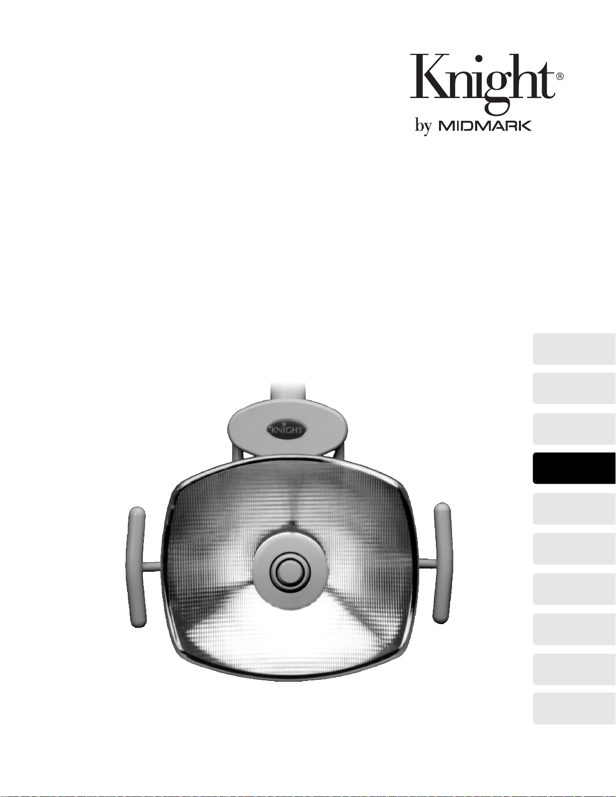
Model L
Go To Table Of Contents
Dental
Lighting
System
Serial Number Prefixes:
LL & PH
Service and
Parts Manual
Model
“L”
FOR USE BY MIDMARK
TRAINED TECHNICIANS ONLY
SF-1618 Part No. 004-0273-00 Rev. E (1/01/04)
Page 2

Go To Table Of Contents
Page 3

TABLE OF CONTENTS
TABLE OF CONTENTS
Section/Paragraph ................................................Page Section/Paragraph...............................................Page
IMPORTANT INSTRUCTIONS
General Safety Instructions ..........................................iii
Safety Alert Symbols....................................................iii
Warra nty Instructions ..................................................iii
SECTION I GENERAL INFORMATION
1.1 Scope of Manual ..........................................1-1
1.2 How to Use Manual ......................................1-1
1.3 Description Of The Model L
Dental O perating Light .................................1-1
1.4 Specifications...............................................1-6
1.5 Pa r ts Replacement Ordering........................1-7
1.6 SpecialTools................................................1-7
SECTION II TESTING AND TRO UBLESHOOTING
2.1 Operational Test (See Figure 2-1 & 2-2) . . ....2-1
2.2 Trouble shooting Procedures.........................2-3
SECTION III SCHEDULED M A INTENANCE
3.1 Scheduled Maintenance ............................. 3-1
SECTION IV MAINTENANCE/SERVICE
INSTRUCTIONS
4.1 Introduction...................................................4-1
4.2 Halogen Bulb Removal / Replacement.........4-1
4.3 Light Head Switch Removal / Installation. ....4-2
4.4 Lamp Socket Assembly
Removal/ Installation...................................4-4
4.5 Continuity Testing.........................................4-6
4.6 Transformer Volta ge Testing.........................4-8
4.7 Transfor mer Continuity Testing.....................4-8
4.8 Cable Connection Testing And Locations...4-10
4.9 Light Head Rotation Adjustment.................4-18
4.10 Wave Washer Replacement.......................4-18
4.11 Flex Ar m Tension Adjustment.....................4-19
4.12 Automatic ON/Off Adjustment....................4-20
4.13 LightFocus Adjustmen t..............................4-21
SECTION V SCHE MATICS AND DIAGRAMS
5.1 Electrical Schemat ics /
Wiring Diagrams ...................................... 5-1
SECTION VI PARTS LIST
6.1 Introduction ................................................. 6-1
6.2 Description Of Co lumns ...............................6-1
6.3 Torque S pec ifications And Impor tant
AssemblyNotes........................................6-1
Unit Mounted Light Assembly - 152924 &
153005 (Sterling Grey).......................... .......6-2
Unit Mounted Light Assembly - 152924-01 &
153005-01 (Pebble Grey)............................. 6-3
Concept L/R As s embly - 153144
(Sterling Grey)..............................................6-4
Concept L/R As s embly - 153144-01
(Pebble Grey)...............................................6-5
Universal Mounted Light A ssembly - 152480
(Sterling Grey)..............................................6-6
Universal Mounted Light A ssembly - 152480-1
& 152577-01 (Pebble Grey) ......................... 6-7
Ceiling Mounted Light Assembly - 152567
(Sterling Grey)..............................................6-8
Ceiling Mounted Light Assembly - 152567-01
152568-01 (Pebble Grey)............................. 6-9
Track Mounted Light Assembly - 152571
(Sterling Grey)............................................ 6-10
Track Mounted Light Assembly - 152571-01 &
152572-01 (Pebble Grey)........................... 6-11
Wall/Cabinet Mounted Ligh t Assembly (Long
Arm) - 152686 (Sterling Grey).................... 6-12
Wall/Cabinet Mounted Ligh t Assembly (Long
Arm) - 152686-01 (Pebble Grey)................ 6-13
Remote Transformer Unit Light Assembly -
152505 (Sterling Grey).......................... .....6-14
Remote Transformer Unit Light Assembly -
152505-01 (Pebble Grey)........................... 6-15
Wall/Cabinet Mounted Ligh t Assembly (Short
Arm) - 152569 (Sterling Grey).................... 6-16
Wall/Cabinet Mounted Ligh t Assembly (Short
Arm) - 152569-01 (Pebble Grey)................ 6-17
Light Head Ass embly - 152481
(Sterling Grey)........................................... 6-18
Light Head Ass embly - 152481-01
(Pebble Grey).............................................6-19
Light Flex Arm Assembly - 152504
(Sterling Grey)............................................ 6-20
Light Flex Arm Assembly - 152504-01
(Pebble Grey)...........................................6-21.*
Unit/Wall Light Fixed Arm Assembly -
152506 (Sterling Grey).......................... .....6-22
Unit/Wall Light Fixed Arm Assembly -
152506-01 (Pebble Grey)........................... 6-23
Universall Light Fixed Arm Assembly -
152482 (Sterling Grey).......................... .....6-24
(*) Indicates that there has been a serial number break for t he illustration
and that there are additional point page(s) foll owing the original page.
© Midmark Corporation 2000 SF-1618 Page i Printed in U.S.A.
Rev. 9/01
Page 4

7$%/(2)&217(176
Return To Table Of Contents
Universall Light Fixed Arm Assembly -
152482-01 & 152591-01 (Pebble Grey)......6-25
Ceiling Light Fixed Arm Assembly -
152566 (Sterling Grey)...............................6-26
Ceiling Light Fixed Arm Assembly -
152566-01 & 152592-01 (Pebble Grey)......6-27
Track Light Fixed Arm Assembly -
152576 (Sterling Grey)...............................6-28
Track Light Fixed Arm Assembly -
152576-01 & 152612-01 (Pebble Grey)......6-29
Cabinet Mount Fixed Arm Assembly -
152684 (Sterling Grey)...............................6-30
Cabinet Mount Fixed Arm Assembly -
152684-01 (Pebble Grey)...........................6-31
Ceiling Mounted Light Tripod Assembly -
149918 (Sterling Grey)...............................6-32
Ceiling Mounted Light Tripod Assembly -
149918-01 (Pebble Grey)...........................6-33
Track / Trolley Assembly - 152603
(Sterling Grey)............................................6-34
Track / Trolley Assembly - 152603-01 &
152609-01 (Pebble Grey)...........................6-35
Trolley Assembly - 152608
(Sterling Grey).. ...... ....... ...... ....... ...... ....... ... 6-36
Trolley Assembly - 152608-01
(Pebble Grey)............................................. 6-37
Wall Mount Assembly - 152544
(Sterling Grey).. ...... ....... ...... ....... ...... ....... ... 6-38
Wall Mount Assembly - 152544-01 &
152549-01 (Pebble Grey)........................... 6-39
Cabinet Mount Assembly - 152683
(Sterling Grey).. ...... ....... ...... ....... ...... ....... ... 6-40
Cabinet Mount Assembly - 152682-01 &
152683-01 (Pebble Grey)........................... 6-41
Light Arm Mounting Comp one nts
(Sterling Grey).. ...... ....... ...... ....... ...... ....... ... 6-42
Light Arm Mounting Comp one nts
(Pebble Grey)............................................. 6-43
Light Mounting Post Kit (48 in.).................. 6-44
COMMENTS............................................................. 7-1
FAX ORDER FORM.................................................. 7-2
© Midmark Corporation 2000 SF-1618
Page ii
Printed in U.S.A.
Page 5
7$%/(2)&217(176
Return To Table Of Contents
General Safety Instructions
Safety First: The primary concern of Midmark Corporation is that this
tained with the safety of the patient and staff in mind. To
assure that services and repairs are completed safely
and correctly, proceed as follows:
(1) Read this entire manual before performing any
services or repairs on this dental lighting system.
(2) Be sure you understand the instructions con-
tained in this manual before attempting to service or repair this dental lighting system.
dental lighting system is main-
Safety Alert Symbols
Throughout this manual are safety alert symbols that
call attention to particular procedures. These items are
used as follows:
DANGER
A DANGER is used for an imminently-
hazardous operating procedure, practice, or condition which, if not correctly followed,
will result in loss of life or serious personal
injury.
NOTE
A NOTE is used to amplify an operating procedure,
practice or condition.
Warranty Instructions
Refer to the Midmark “Limited Warranty” printed in the
Installation and Operation Manual for warranty information. Failure to follow the guidelines listed below will
void the warranty and/or render the 355 Dental Lighting
System unsafe for operation.
• In the event of a malfunction, do not attempt to
operate the dental lighting system until necessary
repairs have been made.
• Do not attempt to disassemble dental lighting system, replace malfunctioning or damaged components, or perform adjustments unless you are one
of Midmark’s authorized service technicians.
• Do not substitute parts of another manufacturer
when replacing inoperative or damaged components. Use only Midmark replacement parts.
WARNING
A WARNING is used for a potentially
hazardous operating procedure, practice, or condition which, if not correctly followed,
could result in loss of life or serious personal
injury.
CAUTION
A CAUTION is used for a potentially haz-
ardous operating procedure, practice, or
condition which, if not correctly followed, could result
in minor or moderate injury. It may also be used to
alert against unsafe practices.
EQUIPMENT ALERT
An EQUIPMENT ALERT is used for an
imminently or potentially hazardous operating procedure, practice, or condition which, if not
correctly followed, will or could result in serious, moderate, or minor damage to unit.
© Midmark Corporation 2000 SF-1618
Page iii
Printed in U.S.A.
Page 6

7$%/(2)&217(176
Return To Table Of Contents
© Midmark Corporation 2000 SF-1618
Page iv
Printed in U.S.A.
Page 7

SECTION I
Return To Table Of Contents
GENERAL INFORMATION
SECTION I
GENERAL INFORMATION
1.1 Scope of Manual
This manual contains detailed troubleshooting, scheduled maintenance, maintenance, and service instructions for Model L Dental Operating Lights. This manual
is intended to be used by authorized service technicians.
1.2 How to Use Manual
A. Manual Use When Performing Scheduled Mainte-
nance.
(1) Perform inspections and services listed in
Scheduled Maintenance Chart (Refer to
para 3.1).
(2) If a component is discovered to be faulty or out
of adjustment, replace or adjust component in
accordance with maintenance / service instructions (Refer to para 4.1).
B. Manual Use When Light Is Malfunctioning And
Cause Is Unknown.
(1) Perform an operational test on Light (Refer to
para 2.1).
(2) Perform troubleshooting procedures listed in
Troubleshooting Guide (Refer to para 2.2).
(3) If a component is discovered to be faulty or out
of adjustment, replace or adjust component in
accordance with maintenance / service instructions (Refer to para 4.1).
C. Manual Use When Damaged Component Is Known.
(1) Replace or adjust component in accordance
with maintenance / service instructions (Refer
to para 4.1).
The Models L comes in seven configurations; a
mounted light, a
cept LR
light, a
arm
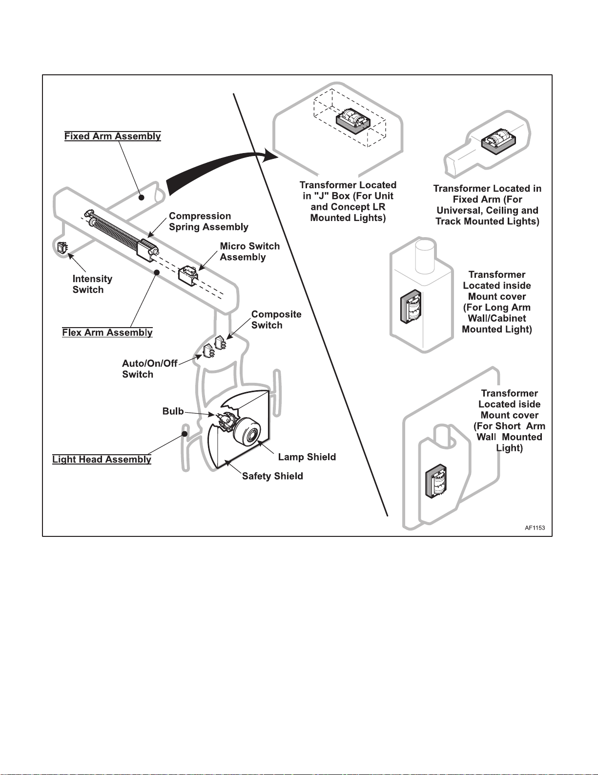
The major serviceable components of the dental light
are the
housing, auto/on/off switch, composite switch, reflector,
safety shield, bulb holder, bulb and shield, the
assembly
assembly, micro switch assembly, auto/on/off wire
assembly, light cable assembly, and the
assembly
switch cable, light cable assembly and the
assembly
Figure 1-1.
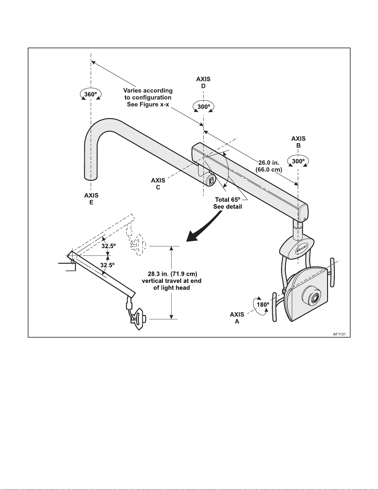
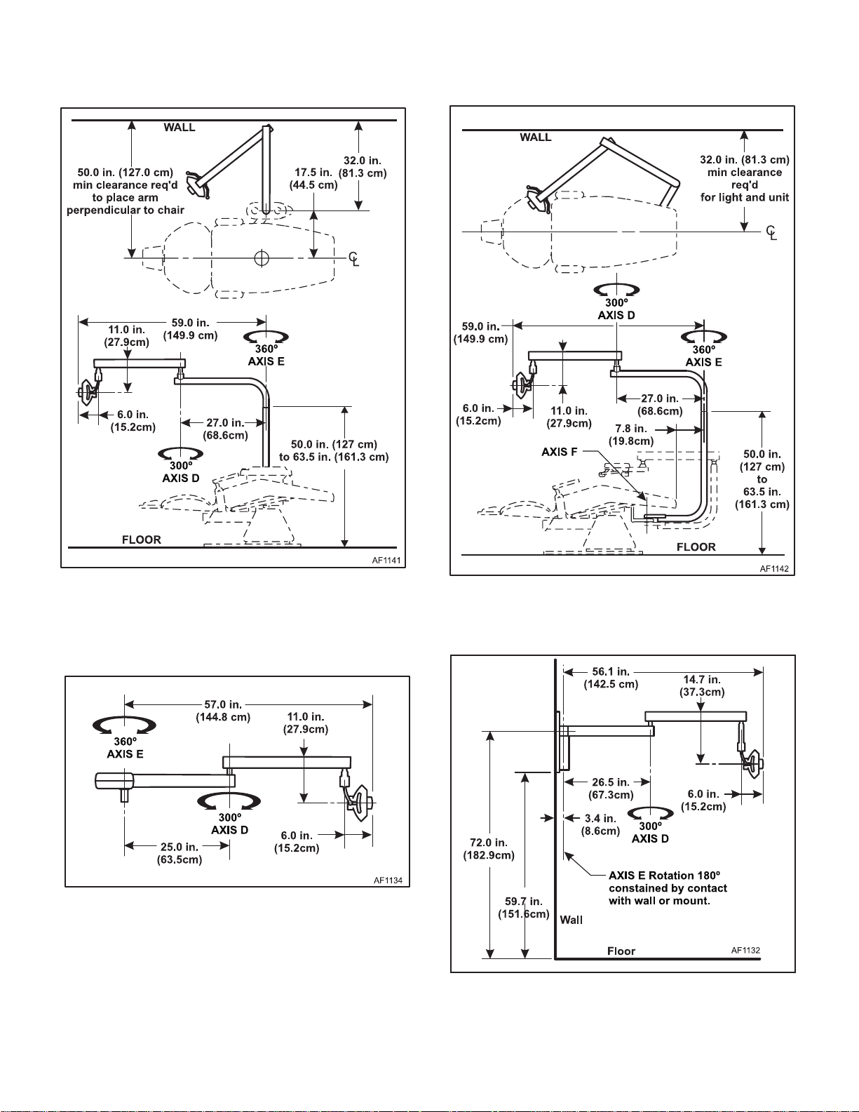
Figure 1-2 illustrates the movement characteristics of all
dental lights. The light head can rotate 360° on the horizontal plane and rotate at the yoke axis approximately
180°. The flex arm can rotate 300° and can move vertically 18.3" (71.9cm) as measured from the front of the
light head. The Fixed arm can rotated 360° at the
mounting points. Because
Figure 1-2 thru 1-9 illustrates the movement characteristics of the various configurations of the dental light.
The
and
points (refered to as axis D). The
280° at axis D, constained by a stop mechanism. The
track
by a stop mechanism, and travels 56.0" (142.2cm)
along it's track. The
light rotates 360° at axis D, constained by the wall or
cabinet. The
at axis D, constained by the wall or cabinet.
light, a
long arm
wall/cabinet mounted light. See Figure 1-1.
lighthead assembly
unit
mounted light,
concept LR
mounted light rotates 280° at axis D, constained
universal
ceiling
wall/cabinet mounted light and a
which includes the compression spring
which includes the intensity switch, intensity
which includes transformer and covers. See
light, all rotate 360° at their mounting
short arm
unit mounted light, a
mounted light, a
which includes light head
universal
ceiling
long arm
wall/cabinet mounted
wall mounted light rotates 180°
track
fixed arm
unit mounted light,
light rotates
unit
con-
mounted
short
flex arm
transformer
B. Theory of Operation (See Figure 5-1 for electri-
cal schematic / wiring diagram)
1.3 Description Of The Model L Dental
Operating Light
A. General Description (See Figures 1-1 thru 1-9).
The Model L Light is designed specifically to provide
shadow free daylight quality light to the oral cavity.
© Midmark Corporation 2000 SF-1618
Page 1-1
Electrical:
The light has a 105, 115 and 125 volt transformer tap to
allow operation over a line voltage range of 95 - 130
volts at a frequency of 50 or 60 hertz. Power Consumption is approximately 110 watts.
Printed in U.S.A.
Page 8
SECTION I
Return To Table Of Contents
GENERAL INFORMATION
A three position rocker switch is provided for the selection of secondary voltages for the bulb. The three positions are labeled high, medium and low corresponding
to the three intensities produced.
A two position rocker switch is provided for the selection of "Operate" or "Composite" color temperature
ranges.
A three position rocker switch is provided for the light
AUTO/ON/OFF. This three position switch controls the
© Midmark Corporation 2000 SF-1618
Figure 1-1. Major Components
bulb voltage but not the line voltage. The AUTO switch
position provides the operator with the ability to control
the on/off function by moving the light head up and
down. The ON/OFF positions override the auto switch
and turns the light on or off.
The transformer is continuously energized unless
power is removed by unplugging the light , or by actuating a separate wall switch wired for that purpose. The
transformer contains an automatically resetting thermal
protector.
Page 1-2
Printed in U.S.A.
Page 9
6(&7,21,
Return To Table Of Contents
*(1(5$/,1)250$7,2 1
Optics
The color temperature of the light is 5250 degrees
kelvin nominally. Due to manufacturing tolerances, a
variation of 750 degrees kelvin from nominal is permitted. Color corre ctio n is acco mplish ed by a front surf ace
dichroic coating. This coating is able to withstand the
normal abrasion which results from routine cleaning for
a period of at least 5 years. Routine cleaning of the
reflector is to be done with soft facial tissue and denatured alcohol on a bi-weekly basis.
© Midmark Corporation 2000 SF-1618
Rev. 3/00
Figure 1-2. General Movement Characteristics
The reflector is approximately 9 in. wide and 8 in. high
and is made of borasilicate glass. It contains 4576 facets to yield maximum uniformity of intensity within the
pattern, and to reduce the production of shadows. The
light pattern at focus is approximately 8 in. wide and 3
in. high and oval shaped. To minimize eye fatigue, the
intensity of the light falls off gradually starting at the
edge of the pattern (feathered). The intensity, 3 inches
from the horizontal axis of the pattern, is less than 5%
of the intensity on the axis. This prevents high intensity
light from striking the patient’s ey e.
Page 1-3
Printed in U.S.A.
Page 10
SECTION I
Return To Table Of Contents
GENERAL INFORMATION
Figure 1-3. Movement Characteristics - Unit
Mounted Light
Figure 1-4. Movement Characteristics - Universal
Unit Mounted Light
Figure 1-5. Movement Characteristics - Concept LR
Unit Mounted Light
Figure 1-6. Movement Characteristics - Short Arm
Wall Mounted Light
© Midmark Corporation 2000 SF-1618
Page 1-4
Printed in U.S.A.
Page 11
SECTION I
Return To Table Of Contents
GENERAL INFORMATION
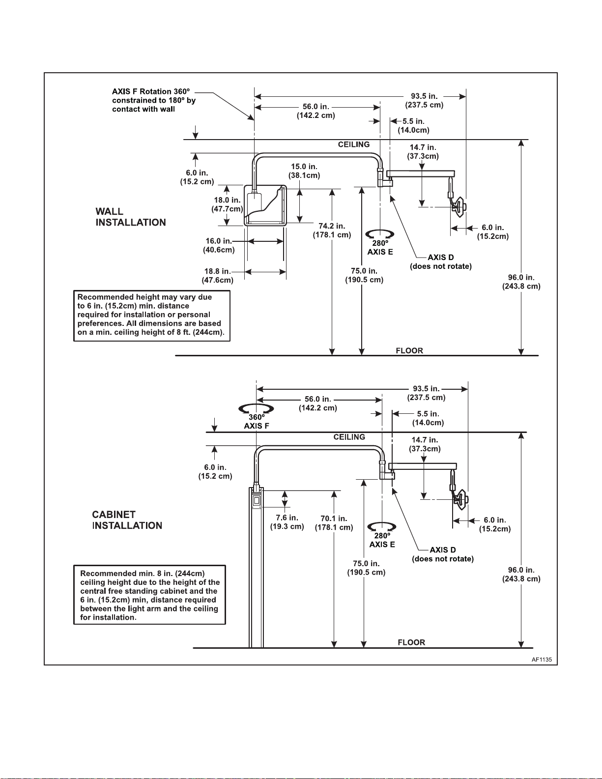
Figure 1-7. Movement Characteristics - Long Arm Cabinet/Wall Mounted Light
© Midmark Corporation 2000 SF-1618
Page 1-5
Printed in U.S.A.
Page 12
SECTION I
Return To Table Of Contents
GENERAL INFORMATION
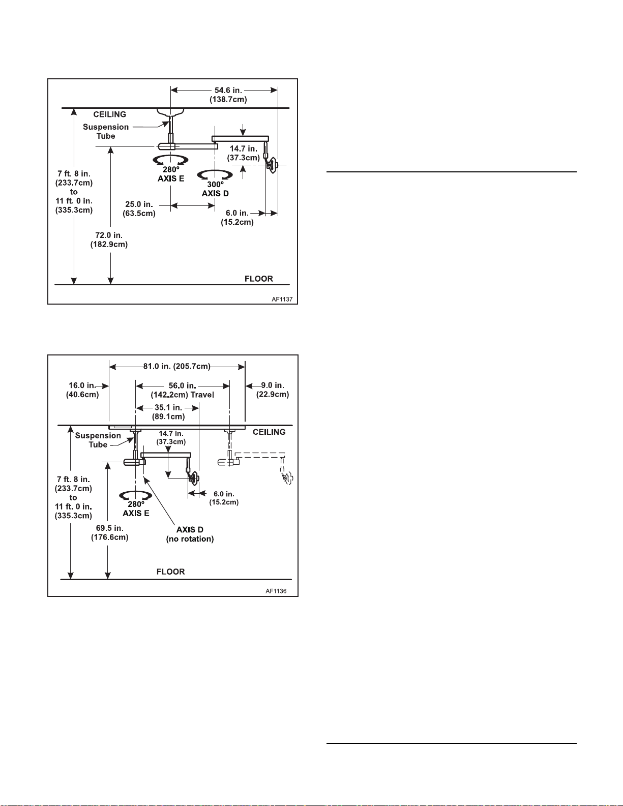
Figure 1-8. Movement Characteristics - Ceiling
Mounted Light
1.4 Specifications
Factual data for Model L Dental Operating Lights is provided in Table 1-1.
Table 1-1. Specifications
Description Data
Weight With Shipping Carton:
All Unit Lights.........................................40 lb (18.2 kg)
Ceiling Light.......................................... 58 lb (26.4 kg)
Track Light..............................................41 lb (18.6 kg)
Track (shipped separate) ..................... 26 lb (11.8 kg)
Tripod (shipped separate) .................... 67 lb (30.5 kg)
Shipping Carton:
All Lights .............. 41 in. "L" x 29 in. "W" x 14 in. "H"
(104 cm x 74 cm x 36 cm)
Track ....................... 82 in. "L" x 8 in. "W" x 8 in. "H"
(208 cm x 20 cm x 20 cm)
Tripod .................... 15 in. "L" x 15 in. "W" x 6 in. "H"
(38 cm x 38 cm x 15 cm)
Figure 1-9. Movement Characteristics - Track
Mounted Light
Electrical Requirements:
Line Voltage 120 VAC ......... 105 - 130 VAC, 60-50 HZ,
1.5 amp, single phase
Recommended Circuit:
A separate (dedicated) circuit is recommended for
this unit. The unit
electrical circuit with other appliances or equipment
unless the circuit is rated for the additional load.
Optical:
Color Temperature:........ 4500 - 6000 Degrees Kelvin
Nominal Intensity: ........1500, 2000, 2500 Footcandles
Focal Length Range:...........................24 - 42 Inches
Lens:
Size:.........................................8.735 x 9.375 Inches
Coating: ............................ ....... . Front Surface Dichroic
Shadow Reduction:...................................2576 Facets
Nominal Pattern Size: ... 3 x 8 Inches Feathered Edge
Bulb:
Base Type......................................... 2 Pin Prefocused
Filament:...................................................... C - 6 Oval
Size:...................................................................G 6.35
Median Life: .................................1200 Hours (1-3 yrs)
Output:.... ................................ 1700 Lum ens Mini mum
Color Temperature:..................... 2950 Degrees Kelvin
Type: ................................................Tungsten Halogen
Wattage:................ Approximately 95 Watts, 17.3 Volts
should not
be connected to an
at focal length of 36 inches
2100, 2700, 3300 Footcandles
at focal length of 27 inches
© Midmark Corporation 2000 SF-1618
Page 1-6
Printed in U.S.A.
Page 13
SECTION I
Return To Table Of Contents
GENERAL INFORMATION
1.5 Parts Replacement Ordering
If a replacement part is required, order the part directly
from the factory as follows:
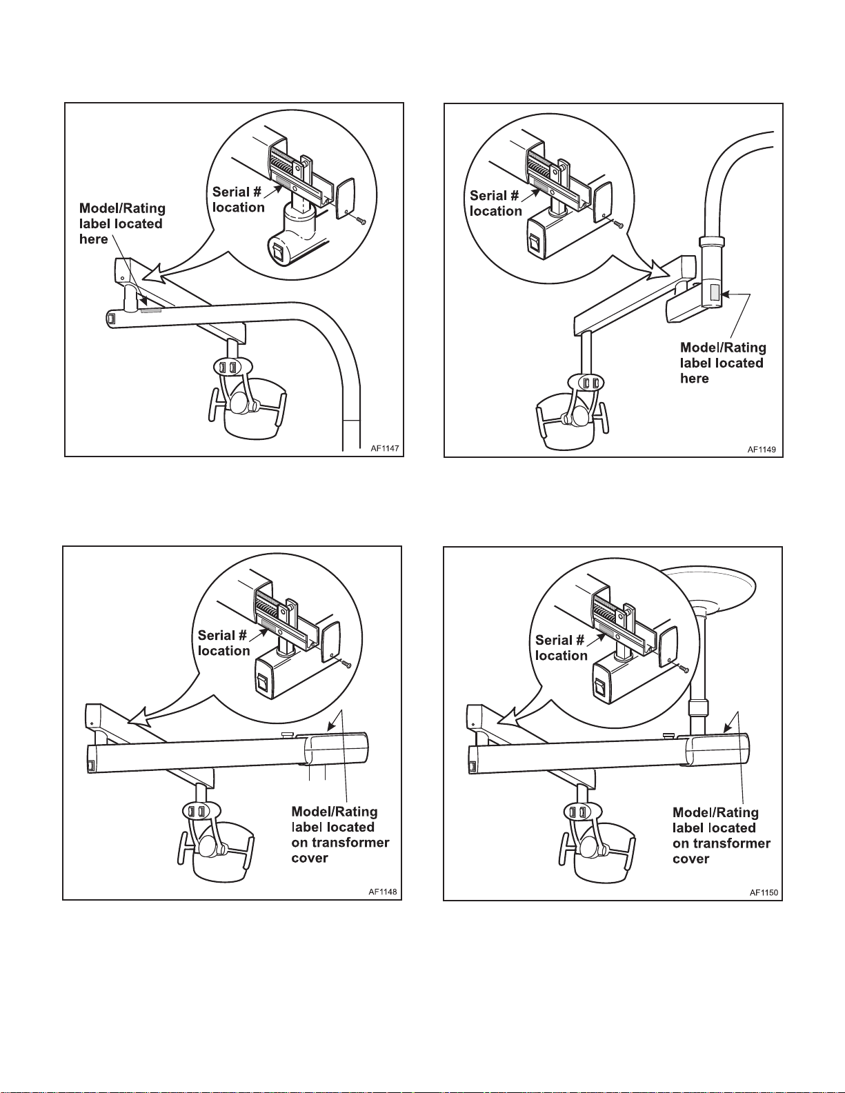
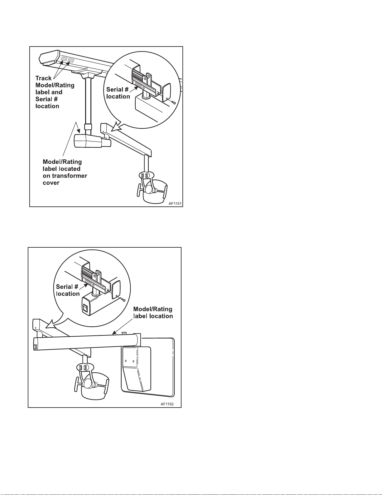
(1) Refer to Figure 1-10 thru 1-15 (shown on follow-
ing pages) to determine the location of the
model number and serial number of the unit
and record this data.
(2) Refer to the Parts List to determine the item
numbers of the parts, part numbers of the
parts, descriptions of the parts, and quantities
of parts needed and record this data (Refer to
para 6.1).
(3) Determine the installation date of the unit and
record this data.
(4) Call Knight with the recorded information and
ask for the Technical Services Department or
use the Fax Order Form (See page 7-2 for Fax
Order Form).
Special Tools
Table 1-2 lists all of the special tools needed to repair
the lighting system, how to obtain the special tools, and
the purpose of each special tool.
Table 1-2.
Description of Special To ol
Multimeter Commercially Available Any Type Used to perform continuity and voltage c hecks.
Torque Wrench Commercially Available Any Type Used to tighten nuts or screws to specified values.
Manufacturer’s
Name / Address / Phone
Manufacturer’s
Part Number
Purpose of Special Tool
© Midmark Corporation 2000 SF-1618
Page 1-7
Printed in U.S.A.
Page 14
SECTION I
Return To Table Of Contents
GENERAL INFORMATION
Figure 1-10. Model Number / Serial Number Location
Unit Mounted Light and Concept LR Light
Figure 1- 12. Mo del Num b er / Se rial Nu mbe r Lo cat ion
Wall/Cabinet Mouted Light
Figure 1-11. Model Number / Serial Number Location
Universal Unit Mouted Light
© Midmark Corporation 2000 SF-1618
Page 1-8
Figure 1-13. Model Number / Serial Number Location
Ceiling Mouted Light
Printed in U.S.A.
Page 15
SECTION I
Return To Table Of Contents
GENERAL INFORMATION
Figure 1-14. Model Number / Serial Number Location
Track Mouted Light
Figure 1-15. Model Number / Serial Number Location
Wall Mouted Light (Short Arm)
© Midmark Corporation 2000 SF-1618
Page 1-9
Printed in U.S.A.
Page 16

SECTION I
Return To Table Of Contents
GENERAL INFORMATION
© Midmark Corporation 2000 SF-1618
Page 1-10
Printed in U.S.A.
Page 17
SECTION II
Return To Table Of Contents
TESTING AND TROUBLESHOOTING
2.1 Operational Test
(See Figure 2-1 & 2-2)
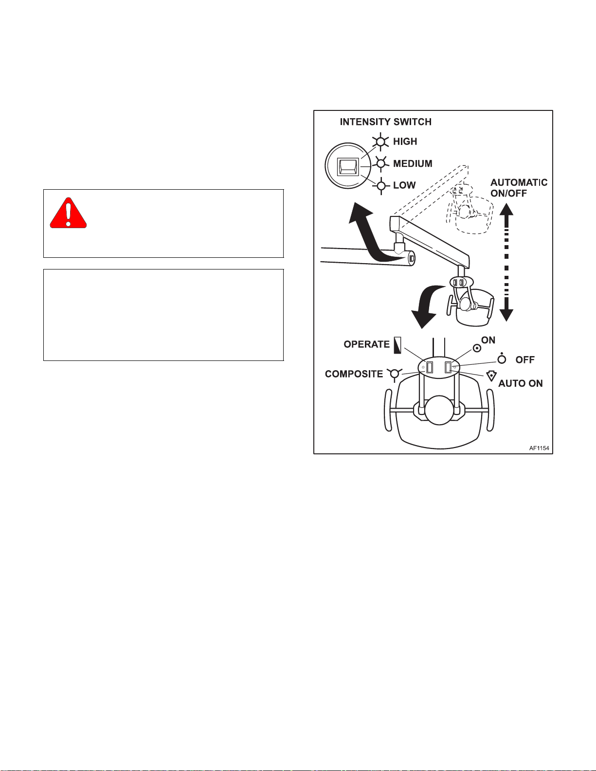
In order to effectively diagnose the malfunction of the
dental light, it may be necessary to perform an opera-
tional test as follows:
W ARNING
Refer to the Operator Manual for com-
plete instructions on operating the dental light. Failure to do so could result in personal
injury .
NOTE
The Operational Test, for the most part, only
describes what should happen when the dental light
is operated. If the dental light does something other
than described refer to the Troubleshooting Guide to
determine the cause of the problem and its correction.
SECTION II
TESTING AND TROUBLESHOOTING
(1) Move the OPERA TE/COMPOSITE switch to the
OPERATE position and then move the THREE
POSITION SWITCH to the AUTO ON position.
Observe.
(2)
the light is lifted up and out of the operating
position, a limit switch in the arm automatically
turns the light off.
Observe.
(3)
tion. The light should come on as it is lowered.
(4) Move the THREE POSITION SWITCH to the
ON position.
Observe.
(5)
position it is placed.
(6) Move the THREE POSITION SWITCH to the
OFF position.
Observe.
(7)
ever position it is placed.
(8) With the light on, move the INTENSITY
SWITCH through all three positions (See Figure
2-1).
Lift the light up until it shuts off. As
Lower the light into operating posi-
The light will remain ON in what ever
The light will remain OFF in what
Figure 2-1. Light Head Switches
Observe
(9)
change from low to medium to high as you
move the switch to these positions.
(10) Move the OPERA TE/COMPOSITE switch to the
COMPOSITE position (See Figure 2-1) and
repeat steps 8 and 9.
(11) Observe. The COMPOSITE position provides
the operator with reduced color temperature
lighting (dimmer light) for working with photosensitive composites. The INTENSITY
SWITCH positions have no effect.
. The intensity of the light should
© Midmark Corporation 2000 SF-1618
Page 2-1
Printed in U.S.A.
Page 18
SECTION II
Return To Table Of Contents
TESTING AND TROUBLESHOOTING
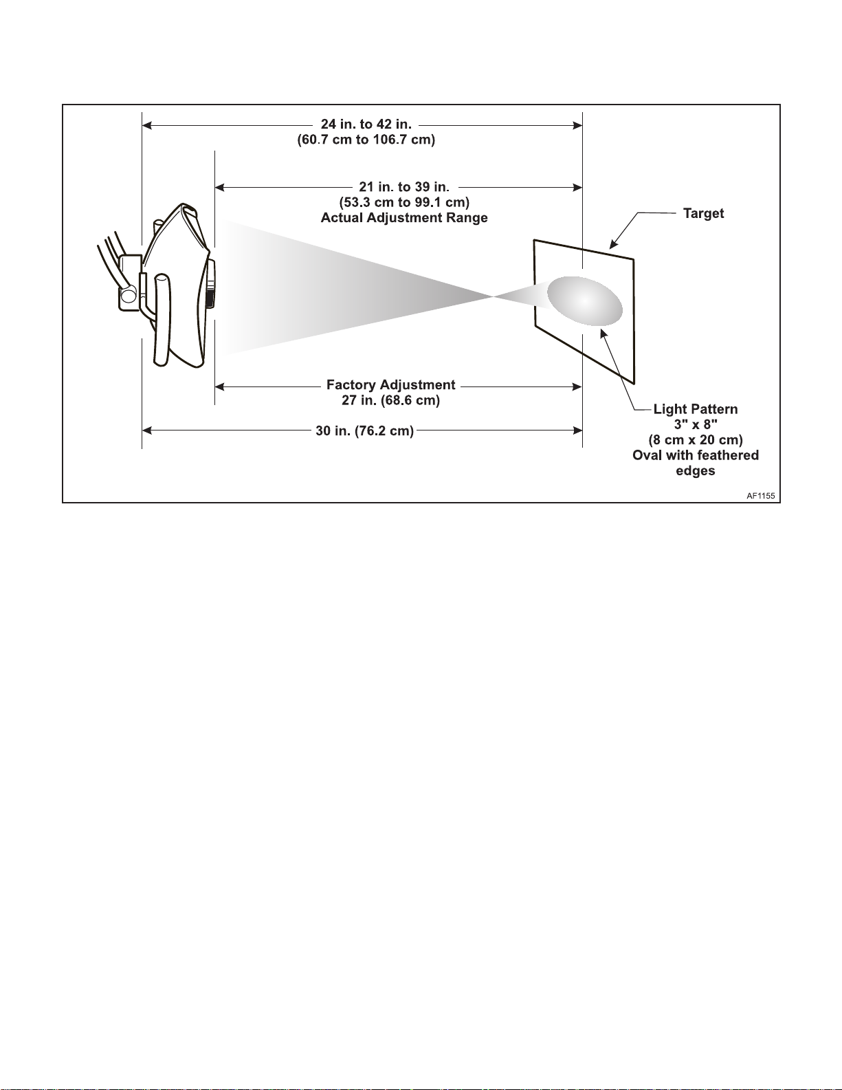
Figure 2-2. Light Pattern Dimensions
(12) Position the light 21 to 39 inches (53 to 99cm)
from a target (wall, chair back, etc.) and move
the OPERATE/COMPOSITE switch to the
OPERATE position. Move the THREE POSITION SWITCH to the ON position (See Figure
2-2).
Observe.
(13)
pattern size of approximately 3 x 8 inches (8 x
20cm), oval in shape, with feathered edges.
(14) While the light is on, test the movement of the
light by rotating the light at its various axis
(Refer to Figure 1-2).
A. Rotate the light head assembly 180° around
Axis A several times.
B. Rotate the light head assembly 300° around
Axis B several times.
C.lift the flex arm assembly up and down verti-
cally at Axis C several times.
The light should present a nominal
Observe.
(15)
tently or stop illuminating when the lighthead
assembly is rotated. Also, the lighthead assembly and /or flex arm assembly should not take
excessive force to rotate, or coast when
released.
(16) Test the movement of the
ing
or
ing location by rotating the fixed arm at Axis D.
(Refer to Figures 1-3 thru 1-9).
Observe.
(17)
tently or stop illuminating when the fixed arm
assembly is rotated. Also, the fixed arm assembly should not take excessive force to rotate, or
coast when released.
(18) Test the movement of the
the mounting location by moving the light along
the length of the track several times, Rotating
the light 300° around Axis D several times
(Refer to Figure 1-9).
The light should not “flash” intermit-
unit, universal, ceil-
wall/cabinet
The light should not “flash” intermit-
mounted light at the mount-
track
mounted light at
D. Rotate the flex arm assembly 300° around
Axis C several times.
© Midmark Corporation 2000 SF-1618
Page 2-2
Printed in U.S.A.
Page 19

SECTION II
Return To Table Of Contents
TESTING AND TROUBLESHOOTING
(19) Observe. The light should not “flash” intermit-
tently or stop illuminating. Also, the fixed arm
assembly
should not
rotate at Axis C, but
should rotate at Axis D. Also, the assembly
should not take excessive force to rotate, or
coast when released.
Table 2-1. Troubleshooting Guide
Problem Symptom Probable Cause Check Correction
Light will not illuminate. After performing the Oper-
ational Test (Para 2.1),
Light will not illuminate
when the ON/OFF/AUTO
switch is in the ON or
AUT O position.
Halogen bulb is burned out. Replace suspect halogen
ON/OFF/AUTO switch in the
light head assembly is defective.
COMPOSITE/
OPERATE switch in the light
head assembly is defective
Main ON/OFF switch in the
junction box is off or defective.
Facility circuit breaker providing power to the unit is
tripped.
Line fuse located in the junction box is blown.
Torn, broken, or disconnected wire between the
lamp socket and the ON/
OFF/AUTO switch.
Bulb socket is corroded
resulting in a bad connection.
Torn, broken, or disconnected wire between the
transformer and the light
head.
Transformer is malfunctioning (If transformer is hot go
to next symptom).
2.2 Table 2-1 is a T r oubleshooting Guide
which is used to determine the
cause of the malfunction.
bulb.
Check continuity of
switch.
Check continuity of
switch.
Check to make sure the
switch is on. If not, check
continuity of switch.
Check to see if facility circuit breaker for unit is
tripped.
Perform a continuity
check on the line fuse.
With a good bulb
installed, perform a continuity test from the center
terminal of the ON/OFF/
AUT O switch (gray wire)
to the gray and white wire
connection in the head.
Refer to Para 4.5.A.
Clean the bulb socket or
replace it.
Perform a continuity test
from the Transformer to
the light head. Refer to
Para 4.5.
Check to see that all connections to the transformer are good. Perform
an AC voltage check on
the primary side. Check
for line voltage. Refer to
Para 4.6.
Replace the halogen bulb.
Refer to Para 4.2
Replace defective switch.
Refer to Para 4.3
Replace defective switch.
Refer to Para 4.3
Replace defective switch.
Refer to Para 4.3. If there is no
power to the switch, the facilities circuit breaker may be
tripped.
If the facility cir cuit breaker is
tripped, determine what
caused the circuit breaker to
trip, correct the problem, and
then reset it / replace the circuit breaker.
Replace the line fuse.
Replace or repair any torn,
broken or disconnected wires
in the light head or replace
lamp socket. Refe r to Para
4.4.
Replace lamp socket. Refer to
Para 4-4.
Replace or repair any torn,
broken or disconnected wire in
the light head, arm, console or
umbilical.
Repair any bad connections to
the transformer . If line v oltage
is not present, see previous
probable causes (Main ON/
OFF, Facility circuit,Line fuse).
© Midmark Corporation 2000 SF-1618
Page 2-3
Printed in U.S.A.
Page 20

Problem Symptom Probable Cause Check Correction
Return To Table Of Contents
Light will not illuminate in
one or more of the lights
switched position.
Table 2-1. Troubleshooting Guide - Continued
Light will not illuminate
when the ON/OFF/AUTO
switch is in the ON or
AUT O position (transformer is hot).
Light will not illuminate or
flashes intermittently when
the light head or arms are
moved.
Missing all of the light
INTENSITY switch positions, high, medium, low
when the COMPOSITE/
OPERATE SWITCH is in
the OPERA TE position, but
the COMPOSITE position
works.
TESTING AND TROUBLESHOOTING
Perform an AC voltage
check on the secondary
side. Check across the
white common on terminal (C1 or C2) and the
four other terminals.
Refer to Para 4.6. (Voltage will be higher due to
a no load condition).
The transformer thermal cutoff has been activated.
There is an intermitting
short, torn, broken or disconnected wire within the light
head or arms.
Intensity switch is defective. Intensity switch is defec-
There is a torn, broken, or
disconnected wire between
the Intensity switch and the
composite-operate switch.
Turn off power to the
transformer and allow it
to cool to reset the thermal cutoff. Disconnect
the wire on the secondary side of the transformer. Check continuity
across the primary side
of the transformer. Refer
to Para 4.7.
After the thermal cut off
has reset, put the black
wire on the transformer
and apply power.
If the transformer does
not get hot, plug the
wires back into the secondary side of the transformer.
Perform a continuity
check on all cable connections. Refer to Para
4.8. and Section V for the
appropriate schematic.
tive. P erform a continuity
check on the switch.
Refer to Para 4-8.
Perform a continuity test
from the wire going from
intensity switch to the
head to the black wire,
center terminal of the
composite-operate
switch. Refer to Section
V for the appropriate
schematic.
SECTION II
If voltages are not present,
transformer is defective.
Replace transformer.
If the primary remains open,
replace the transformer.
If the transformer starts to get
hot, replace the transformer.
If the transformer starts to get
hot, there is a short in the light
assembly . P erform a continuity
test on the light arm. Refer to
Para 4.8.
If the transformer does not get
hot there is an intermitting
short in the light assembly.
Inspect cables and light socket
for exposed wire.
Replace or repair any shorted,
torn, broken or disconnected
wire within the light head or
arms.
Replace defective switch.
Replace or repair any torn,
broken or disconnected wire
within the light head or arms.
© Midmark Corporation 2000 SF-1618
Page 2-4
Printed in U.S.A.
Page 21

SECTION II
Return To Table Of Contents
TESTING AND TROUBLESHOOTING
Table 2-1. Troubleshooting Guide - Continued
Problem Symptom Probable Cause Check Correction
Missing one or more of the
INTENSITY switch positions, high medium or low
when the COMPOSITE/
OPERATE switch is in the
OPERA TE position, b ut the
composite positions works.
There is no illumination
when the COMPOSITE/
OPERATE switch is in the
COMPOSITE position. The
INTENSITY switch positions high, medium or low
work when the COMPOSITE/OPERATE switch is in
the OPERATE position.
Light will not illuminate
when the ON/OFF/AUTO
switch is in the AUTO position and the light is lower
into position. The light
operates normally when
the ON/OFF/AUTO switch
is in the ON position.
Intensity switch is defective. Perform a continuity
There is a torn, broken, or
disconnected wire between
the Intensity switch and the
transformer.
COMPOSITE/OPERATE
switch in the light head is
defective.
There is a torn, broken, or
disconnected wire between
the transformer and the
composite-operate switch in
the light head.
ON/OFF/AUTO switch in the
light head is defective.
The auto micro switch in the
flex arm is defective or misaligned.
There is a torn, broken, or
disconnected wire between
the auto micro switch in the
flex arm and the compositeoperate switch or the on-offauto switch in the light head
ASSEMBLY.
check on the switch.
Refer to Section V for the
appropriate schematic.
Perform a continuity test
from the black wire pin 1
to the black of the intensity switch. Repeat the
test for the orange wire
pin 2 to the green wire at
the intensity switch.
Repeat the test for the
red wire pin 3 to the red
wire of the intensity
switch. Refer to the Illustrations in Para 4.8. &
Section V for the appropriate schematic.
Perform a continuity
check on the switch.
Disconnect power supply .
Perform a continuity test
from the brown wire at
the transformer to the red
wire in the light head.
Refer to the Illustrations
in Para 4.5. & 4.7.
Perform a continuity
check on the switch.
Check the switch to see if
it activates when the flex
arm is lowered. Perform
a continuity check on the
switch.
Perform a continuity test
from the black wire of the
on-off-auto switch to the
micro switch and the
micro switch to the black
wire, center terminal of
the composite-operate
switch.
Replace defective switch.
Replace or repair any torn,
broken or disconnected wire
within the light head or arms.
Replace defective switch.
Replace or repair any torn,
broken or disconnected wire
within the light head, arms,
console or umbilical.
Replace defective switch.
Adjust switch. Refer to Para 4-
12. Replace if defective.
Replace or repair any torn,
broken or disconnected wire
within the light head or arms.
© Midmark Corporation 2000 SF-1618
Page 2-5
Printed in U.S.A.
Page 22

Problem Symptom Probable Cause Check Correction
Return To Table Of Contents
Light head will not remain
in position.
Light flex arm will not stay
in position.
Incorrect light pattern or
intensity.
TESTING AND TROUBLESHOOTING
Table 2-1. Troubleshooting Guide - Continued
When repositioned the
light head, it drifts or falls
downward at the axis
where the handles are connected.
When repositioned the flex
arm, it drifts or falls downward at the axis the flex
arm and fixed arm.
Light is too dim. Switches may be set in the
Light is to pattern is wrong
size or irregular.
The light head rotation is out
of adjustment.
If the light head rotation can
not be adjusted, the adjustment wave washer may be
worn or broken.
The flex arm tension is out of
adjustment and there is not
enough tension on the compression spring to overcome
the weight of the light arm
and head.
wrong position
Dirt on reflector and/or
reflector shield.
The light is out of foc us. Check the light pattern.
Remove the cover on the
back of the light head
and examine the hardware that holds the light
head in position. Refer to
Para 4-9.
Remove the cover on the
back of the light head
and examine the hardware that holds the light
head in position. Refer to
Para 4-9.
Remove the arm cover
and examine the tension
spring and associated
hardware for damage.
Refer to Para 4-11.
Check the position of
each switch.
Check the surface of the
reflector and shield.
Refer to Para 4-13.
SECTION II
Adjust the light head rotation
tension. Refer to Para 4-9.
Replace the wave was her.
Refer to Para 4-10.
Adjust the flex arm tension.
Refer to Para 4-11.
Perform the Operational
Check. Refer to the owner’s
manual or Refer to Para 2-1 in
this manual.
Clean the reflector and shield.
Refer to Para 4.2.B.
Adjust the light head focus.
Refer to Para 4-13.
© Midmark Corporation 2000 SF-1618
Page 2-6
Printed in U.S.A.
Page 23

SCHEDULED MAINTENANCE
Return To Table Of Contents
SECTION III
SCHEDULED MAINTENANCE
SECTION III
3.1 Scheduled Maintenance
periodically on the Model L dental lighting system.
These inspections and services should be performed as
Table 3-1 is a Scheduled Maintenance Chart which lists
often as indicated in the chart.
the inspections and services that should be performed
Table 3-1. Scheduled Maintenance
Interval Inspection or Service What to Do
Semi-annually Obvious damage Visually check condition of lighting system for obvious damage such as: cracks in components,
Fasteners / hardware Check lighting system for missing or loose fasteners / hardware. Replace any missing hardware
Warning and instructional
decals
Light Mount Check the rigididity of the ceiling, track, or wall for stability and sturdiness. Strengthen supports if
Surface cleaning
Integrity of wiring and / or
connections
Rotation of all axis Check each axis to ensure ease of movement and positioning with no drifting after being released.
Operational Test Perform an Operational Test to determine if the light is operating within its specifications. Refer to
missing components, dents in components, or any other visible damage which would cause the
lighting system to be unsafe to operate or would compromise its performance. Repair lighting system as necessary.
and tighten any loose hardware as necessary.
Check for missing or illegible decals. Replace decals as necessary.
necessary and tighten any loose bolts. Check to see if the light fixed arm is level. If not, level the
the light at the mount.
Painted surfaces
Use a clean, soft tissue dampened with denatured alcohol and gently wipe the surfaces of the
reflector.
wipe both sides of the reflector cover, taking care not to scratch the surface. Refer to para 4.2.B.
Move each axis thru its full range of motion while observing the light beam for intermittent flickering
or light beam going out completely. Repair wiring or wiring connections as necessary.
Make sure each axis cannot rotate more than is specified in Section I. If so, replace pivot stops /
pivot bearing stops as necessary.
para 2.1. Replace or adjust any malfunctioning components.
Reflector cover
- Wipe the painted surfaces of your Model L Light with a damp cloth.
- Use a clean, soft tissue dampened with denatured alcohol and gently
Reflector
-
© Midmark Corporation 2000 SF-1618
Page 3-1
Printed in U.S.A.
Page 24

SECTION III
Return To Table Of Contents
SCHEDULED MAINTENANCE
© Midmark Corporation 2000 SF-1618
Page 3-2
Printed in U.S.A.
Page 25
SECTION IV
Return To Table Of Contents
MAINTENANCE / SERVICE INSTRUCTIONS
4.1 Introduction
WARNING
Refer to the Operator Manual for com-
plete instructions on operating the dental light. Failure to do so could result in personal
injury .
NOTE
Perform an operational test on the dental light after
the repair is completed to confirm the repair was
properly made and
The following paragraphs contain removal, installation,
repair, and adjustment procedures for the dental light.
all
malfunctions were repaired.
SECTION IV
MAINTENANCE / SERVICE
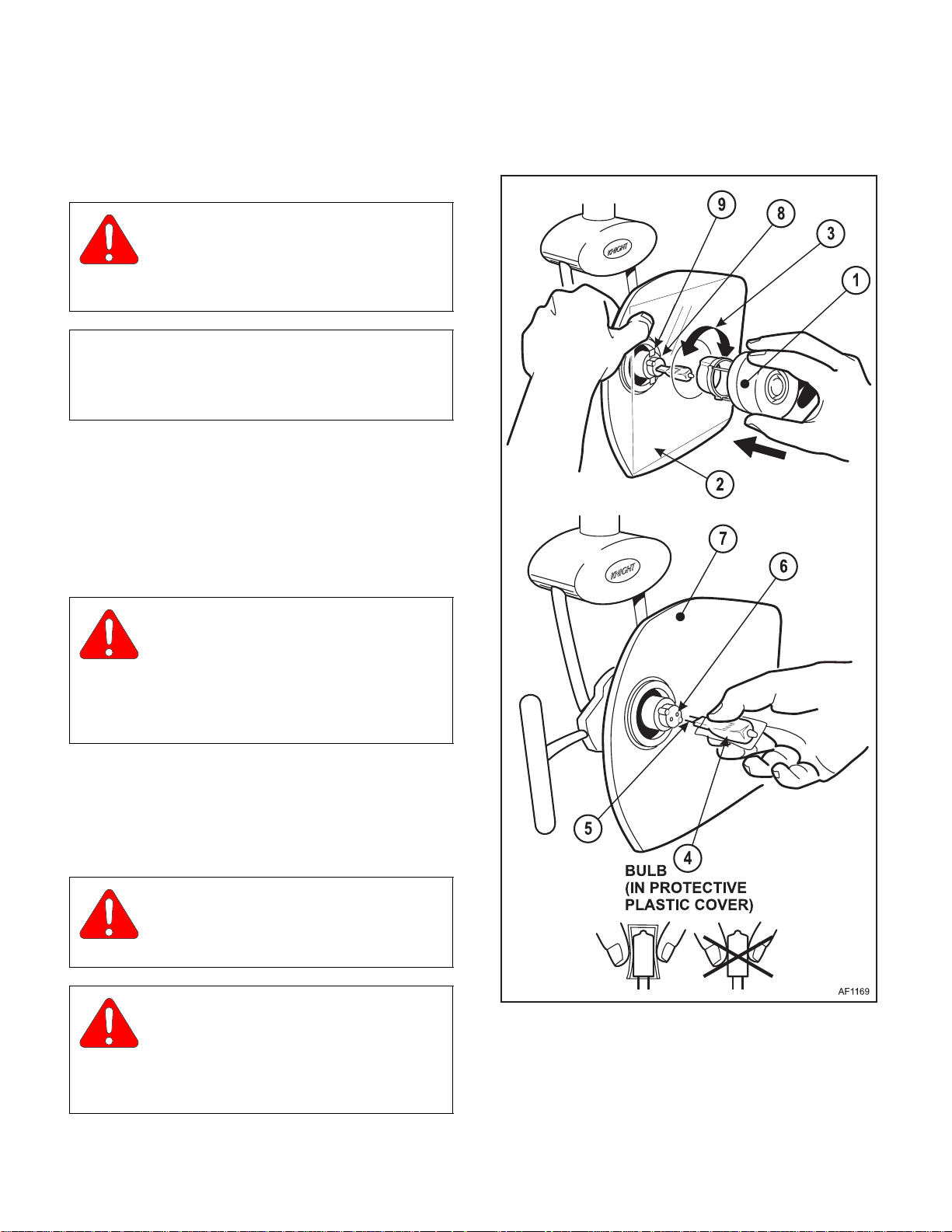
4.2 Halogen Bulb
Removal / Replacement
A. Removal
WARNING
Always disconnect all electrical power
to the unit before removing any of the
unit's access panels or making any repairs to prevent the possibility of electrical shock. Failure to
comply with these instructions could result in
serious personal injury or death.
(1) Disconnect electrical power to the light.
(2) Remove the lamp shield (1) and reflector cover
(2) by pushing in and turning the lamp shield
counter clockwise
(3) (See Figure 4-1).
CAUTION
Bulb may be HOT! Always allow bulb to
cool for 4-5 minutes before attempting to
remove.
CAUTION
Install the bulb without removing its pro-
tective plastic cover. Finger marks left on
the bulb glass during installation will reduce the bulb
life. If the bulb is accidentally handled, wipe it clean
immediately with denatured alcohol.
© Midmark Corporation 2000 SF-1618
Page 4-1
Figure 4-1. Halogen Bulb Removal/Replacement
(3) Remove the bulb (4) by pulling straight out.
Printed in U.S.A.
Page 26
SECTION IV
Return To Table Of Contents
MAINTENANCE / SERVICE
B. Installation
(4) Use a clean, soft tissue dampened with dena-
tured alcohol and gently wipe the surfaces of
the reflector (7).
(5) Use a clean, soft tissue dampened with dena-
tured alcohol and gently wipe both sides of the
reflector cover (2 ), taking care not to scrat ch the
surface.
EQUIPMENT ALERT
Do not use solvents, abrasive cloths or
cleaners, as they may damage the coating
surface of the reflector and the reflector cover.
(6) To install the new bulb , align the contact pins (5)
with the socket holes (6) and press the bulb in
firmly.
(7) Place the reflector cover (2) in position over the
reflector (7). Insert the lamp shield (1) through
the hole in the reflector cover (2) and onto the
lamp socket (8) while aligning the locking tabs
(9). Push in and turn the lamp shield approxi-
mately 1/8-turn
clockwise
(3) to lock in place.
4.3 Light Head Switch Removal / Installation
NOTE
Compare your light wiring configuration and serial
number with the illustration in Figures 4-2 and follow
either procedure 1 or 2 accordingly.
Procedure #1 (for configuration #1)
A. Removal
(1) Disconnect electrical power to the light.
(2) Remove the light switch cover (1) by removing
the two cover screws (2) (See Figure 4-2).
NOTE
Mark the wires or make note of the wire locations on
the switch to aid in the installation of the new switch.
DANGER
Do not operate the light without the
plastic reflector cover (2) in place.
Operating the light without the cover could result
in personal injury.
© Midmark Corporation 2000 SF-1618
Page 4-2
Printed in U.S.A.
Page 27
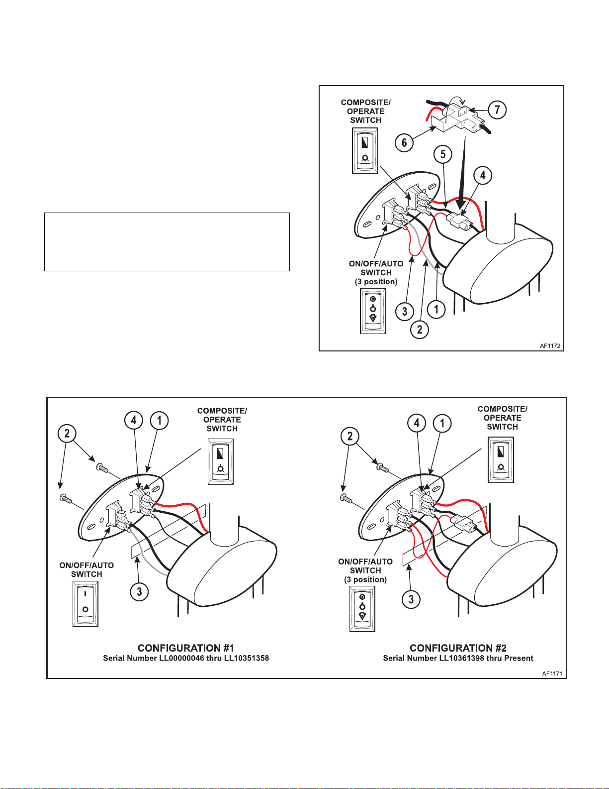
(3) Disconnect the wires (3) and remove the switch
Return To Table Of Contents
by pressing the tabs (4) on the bottom and top
of the switch.
B. Installation
(4) Insert the new switch in the slot where the old
switch was located.
(5) Connect the wires (3) to the new switch in the
same location as the old switch.
NOTE
If the ON/OFF/AUTO switch is being replaced with
the newer 3 position switch, the light head will need
to be re-configured as follows:
C. Re-configuration
(6) Plug the black wire (1) into the top position on
the ON/OFF/AUTO switch and plug the gray
wire (2) into the middle position. Plug the new
red wire (3) into the bottom position (See Figure
4-3).
SECTION IV
MAINTENANCE / SERVICE
Figure 4-3. Switch Re-configuration
© Midmark Corporation 2000 SF-1618
Figure 4-2. Switch Wiring Configurations
Page 4-3
Printed in U.S.A.
Page 28

SECTION IV
Return To Table Of Contents
MAINTENANCE / SERVICE
(7) Attach the connector (4) to the black composite
switch wire (5) and insert the new red wire (3)
into the connector.
(8) Fold the connector tab (6) over and press the
conductor blade (7) in to the wires
(9) Replace the switch cover (1) and screws (2).
Procedure #2 (for configuration #2)
A. Removal
(1) Disconnect electrical power to the light.
(2) Remove the light switch cover (1) by removing
the two cover screws (2) (See Figure 4-2).
.
NOTE
Mark the wires or make note of the wire locations on
the switch to aid in the installation of the new switch.
(3) Disconnect the wires (3) and remove the switch
by pressing the tabs (4) on the bottom and top
of the switch.
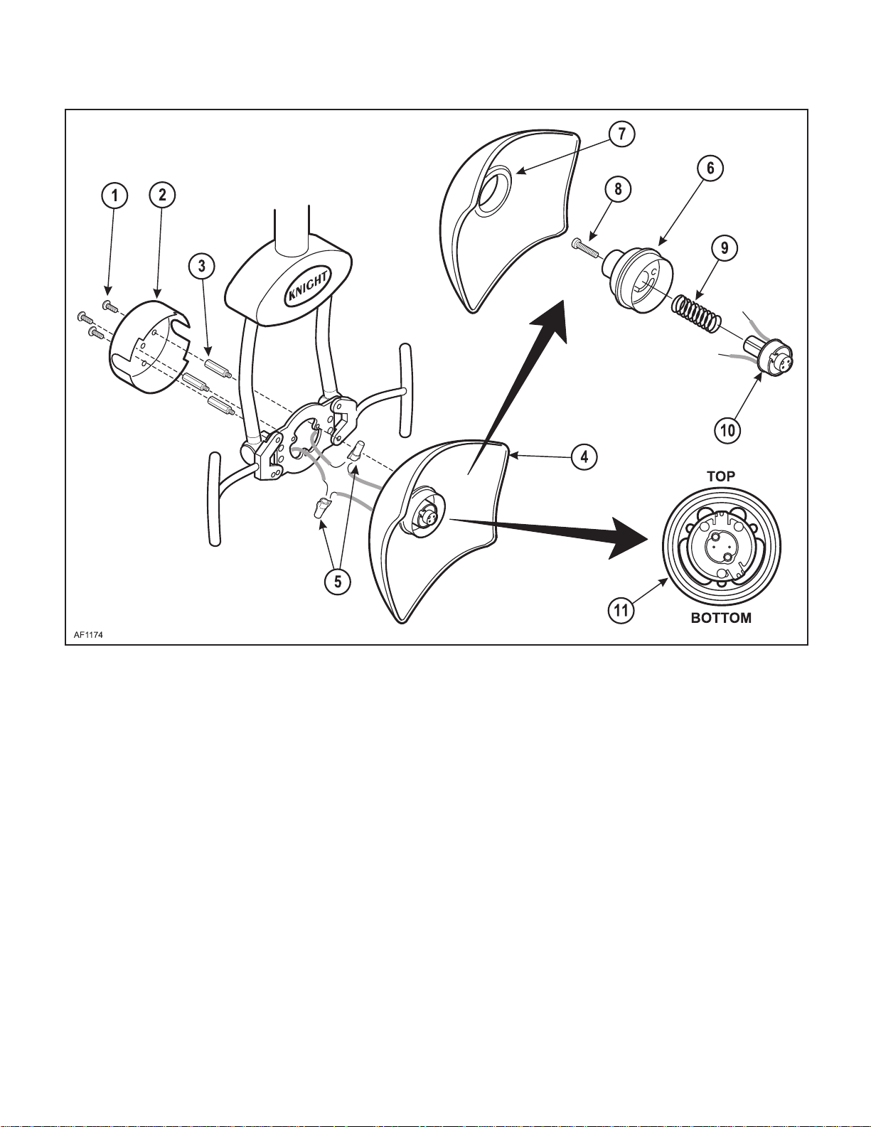
4.4 Lamp Socket Assembly Removal /
Installation
A. Removal
(1) Disconnect electrical power to the light.
(2) Remov e three cover screws (1) and the light
head cover (2) (See Figure 4-4).
(3) Remove three standoffs (3), the reflector (4)
and 2 wire nuts (5)
(4) Pull the lens support housing (6) out of the
grommet (7) in the reflector.
(5) Remove the socket head screw (8), spring (9)
and lamp socket (10) from the lens support
housing.
B. Installation
(6) Replace the lamp socket (10) and reassemble
all the parts. Be sure to orientate the lens support as shown (11).
.
B. Installation
(4) Insert the new switch in the slot where the old
switch was located.
(5) Connect the wires (3) to the new switch in the
same location as the old switch.
(6) Replace the switch cover (1) and screws (2).
(7) Before using, the light focus will need to be
adjusted (See para 4-13)
.
© Midmark Corporation 2000 SF-1618
Page 4-4
Printed in U.S.A.
Page 29
SECTION IV
Return To Table Of Contents
MAINTENANCE / SERVICE
Figure 4-4. Lamp Holder Assembly Removal / Installation
© Midmark Corporation 2000 SF-1618
Page 4-5
Printed in U.S.A.
Page 30
SECTION IV
Return To Table Of Contents
MAINTENANCE / SERVICE
4.5 Continuity Testing
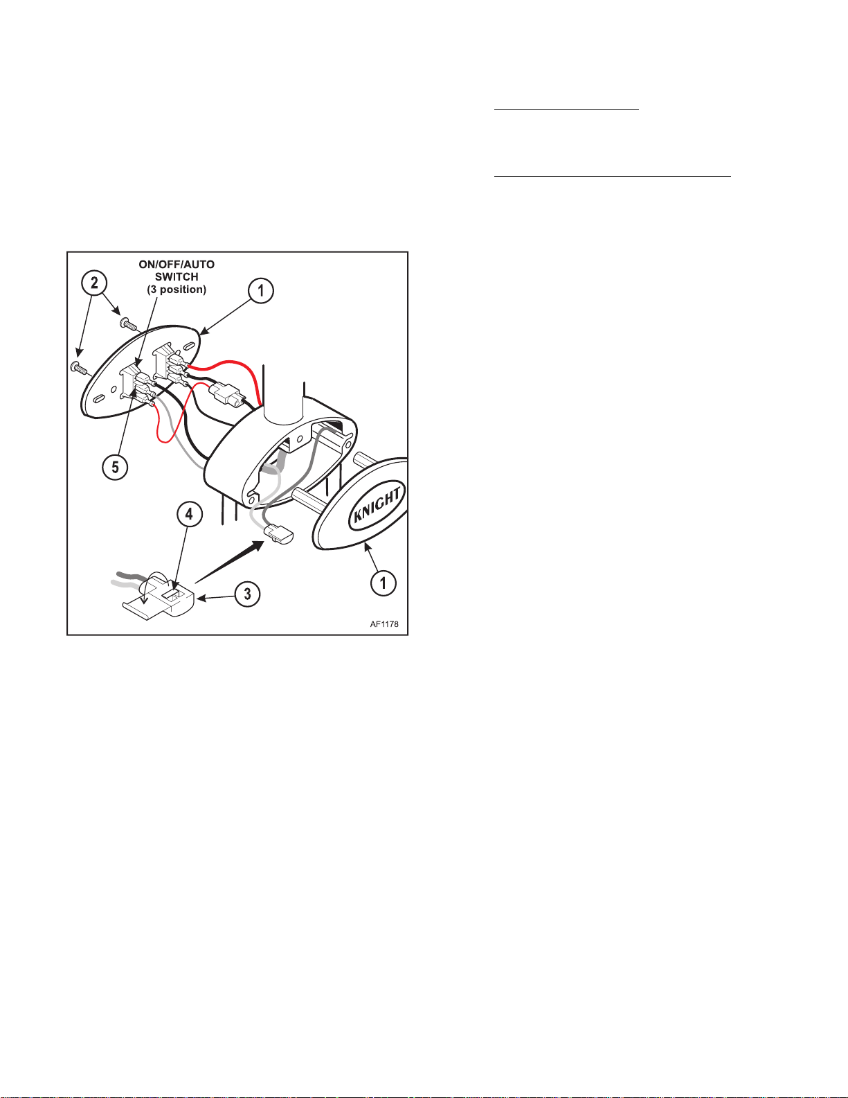
A. Light Head Test
(1) Disconnect electrical power to the light.
(2) Remove the light switch covers (1) by removing
the two cover screws (2) (See Figure 4-5).
(4) Unit mounted light only:
Check for continuity between the metal tab (4)
in the connector and the middle position (white
wire) on the 9 pin light plug (5) at the APC (6).
Track, ceiling, wall and universal lights:
Check for continuity between the metal tab (4)
in the connector and the white wire on position
C2 (7) on the ligh t tr an sf orme r (8) Refer to Para
1-3 for transformer locations.
Figure 4-5. Light Head Continuity Test
(3) Insert a good bulb into the bulb socket.
(4) Open the connector cover (3) that connects the
common white and gray wires.
(5) Check for continuity between the metal tab (4)
in the connector and the middle position on the
ON/OFF/AUTO switch (5).
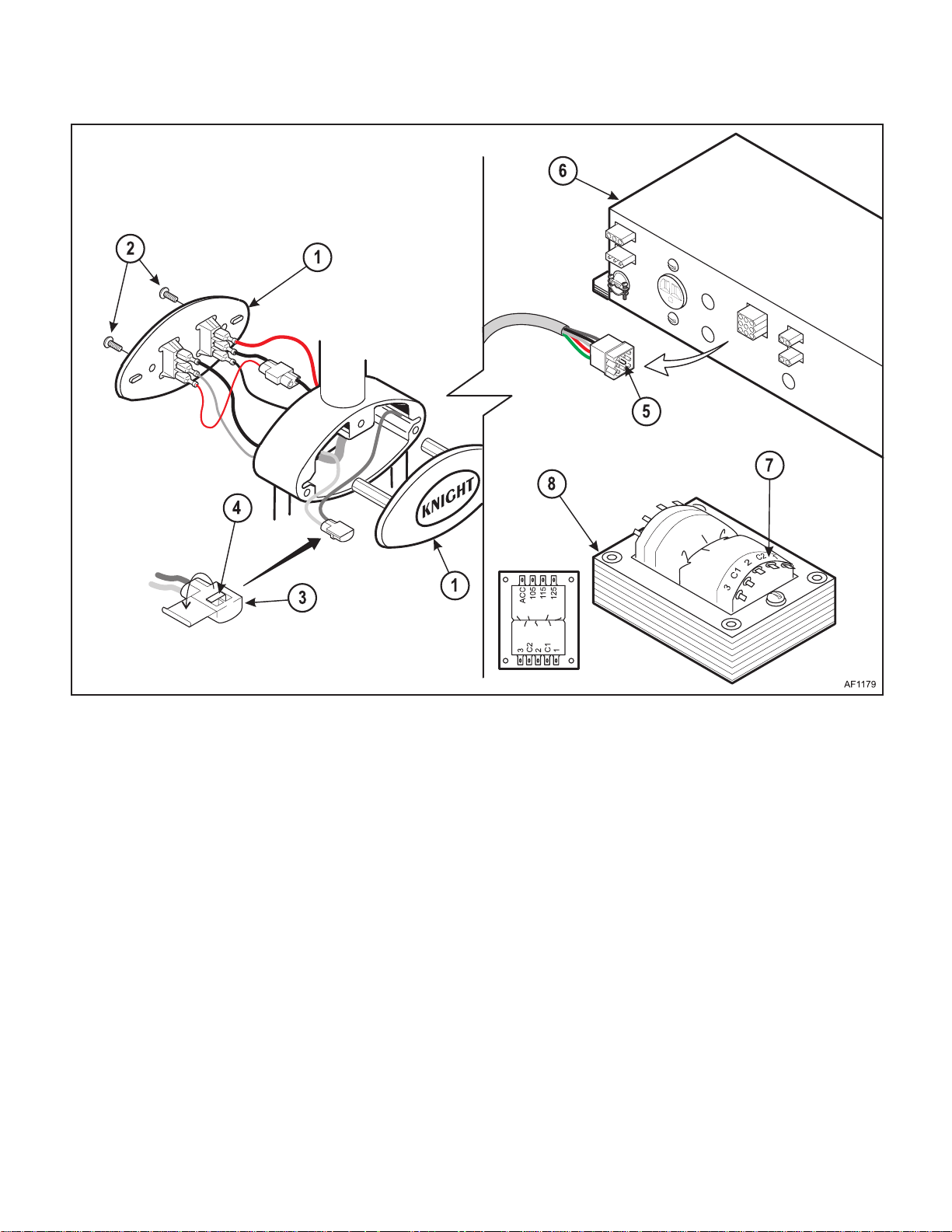
B. Transformer to Light Head
(1) Disconnect electrical power to the light.
(2) Remove the light switch covers (1) by removing
the two cover screws (2) (See Figure 4-6).
(3) Open the connector cover (3) that connects the
common white and gray wires.
© Midmark Corporation 2000 SF-1618
Page 4-6
Printed in U.S.A.
Page 31
SECTION IV
Return To Table Of Contents
MAINTENANCE / SERVICE
Figure 4-6. Tran sformer to Light Head Continuity Test
© Midmark Corporation 2000 SF-1618
Page 4-7
Printed in U.S.A.
Page 32
SECTION IV
Return To Table Of Contents
MAINTENANCE / SERVICE
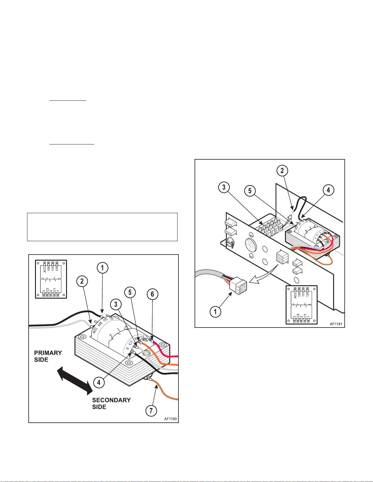
4.6 Tr ansformer Voltage Testing
(1) Remove transformer cover. Refer to Section I,
Figure 1-1 for transformer location.
(2) Connect electrical power to the light.
(3) Primar y Si de:
Check the voltage across the black wire located
at position 115 (1) to the white located at posi-
tion ACC (2) on the primary side (See Figure 4-
7).
(4) Secondar y Side:
Check the voltage across the white common
wire located at position C1 or C2 (3) to the other
four terminals. (See Figure 4-7). The voltages
will read as follows:
(4) Black wire position 3 = 20+ vac
(5) Orange wire position 2 = 18+ vac
(6) Red wire position 1 = 17+ vac
(7) Brown wire position 4 = 10+ vac
NOTE
The voltage listed may be higher due to the no load
condition. Also, the voltage is lower on the C2 tap.
4.7 Transformer Continuity Testing
A. Unit mounted Light and concept LR with APC.
(1) Disconnect electrical power to the light and
remove the APC cover. Refer to Section I, Figure 1-1 for transformer location.
(2) Unplug the 9 pin connector from the APC (1)
and disconnect the black wire (2) on the primary side from the terminal block (3).
(3) Check the continuity from the black wire on the
115 VAC tap of the transformer (4) to the ACC
position (5).
Figure 4-7. Transformer Voltage Testing
© Midmark Corporation 2000 SF-1618
Page 4-8
Figure 4-8. Transformer Continuity Testing Unit
mounted Light and concept LR with APC
Printed in U.S.A.
Page 33
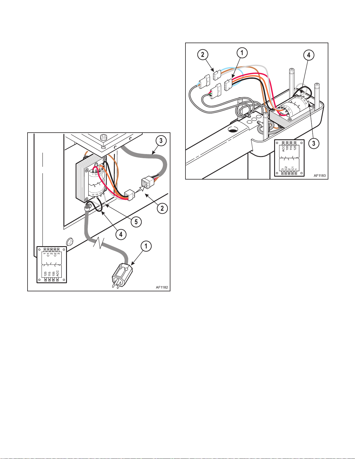
B. Wall/Cabinet mounted Light.
Return To Table Of Contents
(1) Disconnect electrical power to the light (1) and
remove transformer cover. Refer to Section I,
Figure 1-1 for transformer location.
(2) Unplug the 9 pin connector (2) from the light
cable (3).
(3) Check the continuity from the wire at the 115
VAC tap on the t r an sformer (4) to the ACC posi-
tion (5)
SECTION IV
MAINTENANCE / SERVICE
Figure 4-9. Tran sformer Continuity Testing Wall/
Cabinet mounted
C. Universal mounted Light.
(1) Disconnect electrical power to the light and
remove transformer cover. Refer to Section I,
Figure 1-1 for transformer location.
(2) Unplug the 4 pin connector (1) and the 3 pin
connector (2).
Figure 4-10. Transformer Continuity Testing U niver -
sal mounted Light
D. Ceiling mounted Light.
(1) Disconnect electrical power to the light and
remove the transformer cover. Refer to Section
I, Figure 1-1 for transformer location.
(2) Unplug the 4 pin connector (1) and the 3 pin
connector (2).
(3) Check the continuity from the 115 VAC tap on
the transformer (3) to the ACC position (4).
E. Track mounted Light.
(1) Disconnect electrical power to the light and
remove the transformer cover. Refer to Section
I, Figure 1-1 for transformer location
(2) Unplug the 3 pin connector (1).
(3) Check the continuity from the 115 VAC tap on
the transformer (3) to the ACC position (4).
(3) Check the continuity from the 115 VAC tap on
the transformer (3) to the ACC position (4).
© Midmark Corporation 2000 SF-1618
Page 4-9
Printed in U.S.A.
Page 34
SECTION IV
Return To Table Of Contents
MAINTENANCE / SERVICE
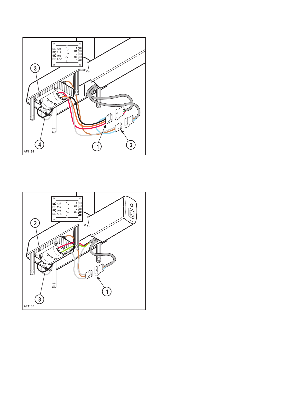
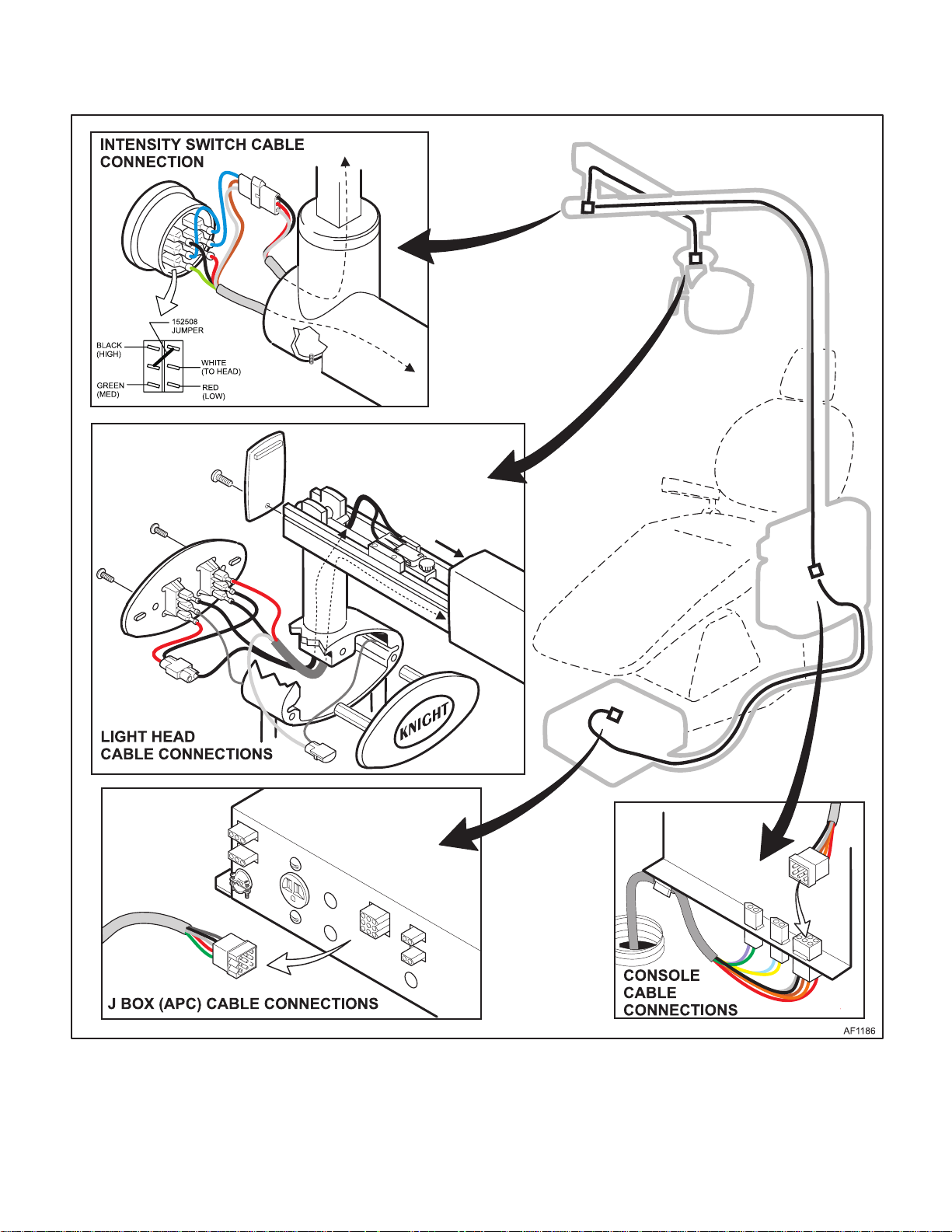
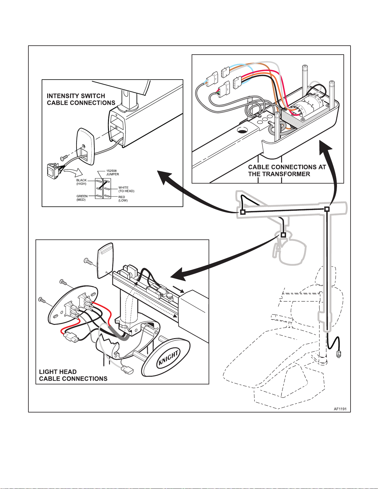
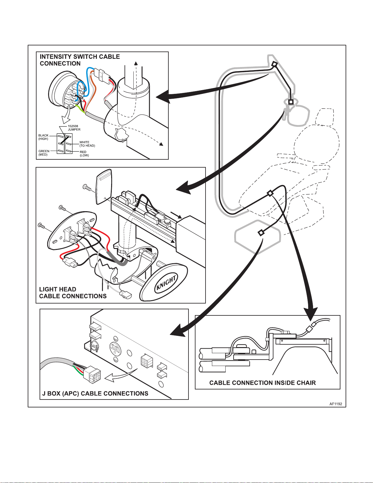
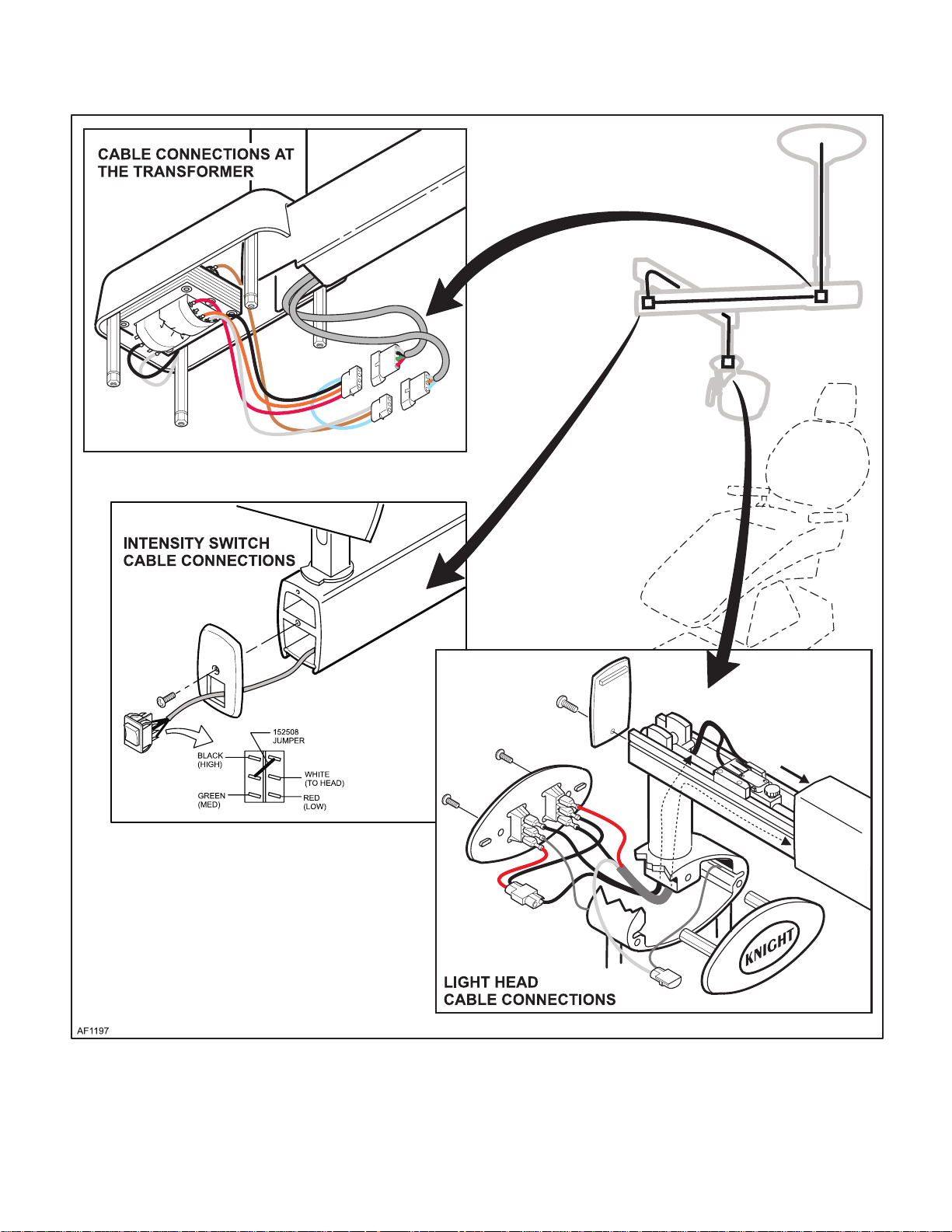
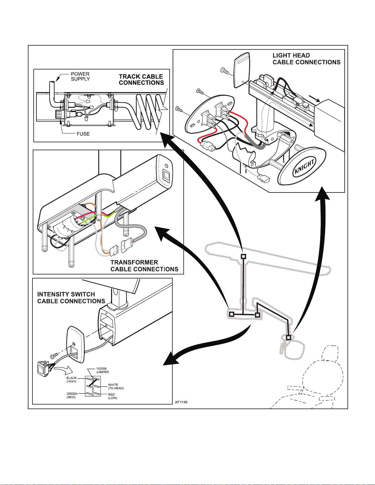
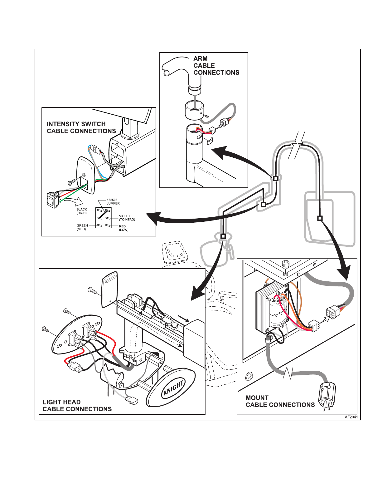
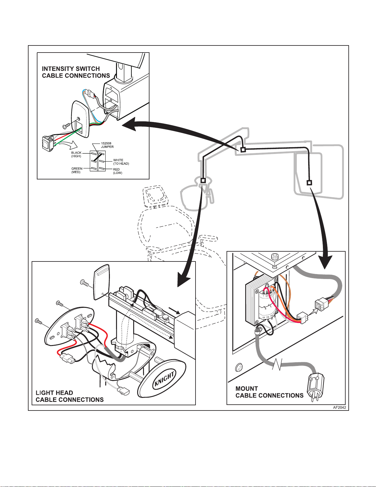
4.8 Cable Connection Testing and Locations
(1) Disconnect electrical power to the light and
remove the covers. Refer to Figure 4-13 thru 419 for connection locations.
(2) Continuity Test s:
Before performing continuity test at the various
cable connections, disconnect the secondary
side of the transformer to avoid getting a false
reading through the transformer. Check
between the wires and the ground for shorts.
(3) Checking voltage:
All voltage checks are referenced from the
white wire C2 or C1 depending on the how the
light is mounted. Refer to Section V.
Figure 4-11. Transformer Continuity Testing Ceiling
mounted Light
Figure 4-12. Transformer Continuity Testing Track
mounted Light
© Midmark Corporation 2000 SF-1618
Page 4-10
Printed in U.S.A.
Page 35
SECTION IV
Return To Table Of Contents
MAINTENANCE / SERVICE
Figure 4-13. Cable Connections - Unit Mounted Light
© Midmark Corporation 2000 SF-1618
Page 4-11
Printed in U.S.A.
Page 36
SECTION IV
Return To Table Of Contents
MAINTENANCE / SERVICE
Figure 4-14. Cable Connections - Universal Mounted Light
© Midmark Corporation 2000 SF-1618
Page 4-12
Printed in U.S.A.
Page 37
SECTION IV
Return To Table Of Contents
MAINTENANCE / SERVICE
Figure 4-15. Cable Connections - Concept LR Light
© Midmark Corporation 2000 SF-1618
Page 4-13
Printed in U.S.A.
Page 38
SECTION IV
Return To Table Of Contents
MAINTENANCE / SERVICE
Figure 4-16. Cable Connections - Ceiling Mounted Light
© Midmark Corporation 2000 SF-1618
Page 4-14
Printed in U.S.A.
Page 39
SECTION IV
Return To Table Of Contents
MAINTENANCE / SERVICE
Figure 4-17. Cable Connections - Track Mounted Light
© Midmark Corporation 2000 SF-1618
Page 4-15
Printed in U.S.A.
Page 40
SECTION IV
Return To Table Of Contents
MAINTENANCE / SERVICE
Figure 4-18. Cable Connections - Wall/Cabinet mounted Light
© Midmark Corporation 2000 SF-1618
Page 4-16
Printed in U.S.A.
Page 41
SECTION IV
Return To Table Of Contents
MAINTENANCE / SERVICE
Figure 4-19. Cable Connections - Wall/Cabinet mounted Light (Short Arm)
© Midmark Corporation 2000 SF-1618
Page 4-17
Printed in U.S.A.
Page 42
SECTION IV
Return To Table Of Contents
MAINTENANCE / SERVICE
4.9 Light Head Rotation Adjustment
(1) Disconnect electrical power to the light.
(2) Remove the back cover (1) and three screws.
(2) (See figure 4-20).
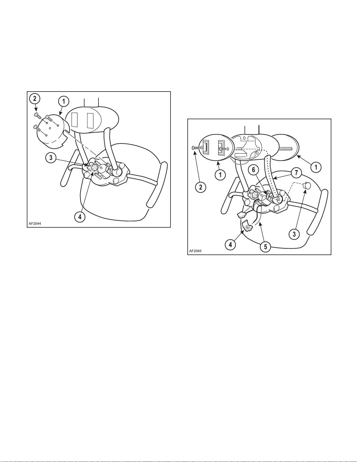
4.10 Wave Washer Replacement
A. Rem oval
(1) Disconnect electrical power to the light.
(2) Remove the back cover (See Para 4.9)
(3) Remove the light covers (1) by removing two
screws (2) (See Figure 4-21).
Figure 4-20. Light Head roatation adjustment
(3) Loosen each set screw (3) one turn maximum,
using an allen wrench.
(4) Using an open end wrench, tighten the adjust-
ing nuts (4) on each side 1/8 turn. Check the
movement of the light head. Repeat until the
tension is satisfactory.
(5) Retighten the set screws (3) and replace the
back cover (1) and screws (2).
Figure 4-21. Wave Washer replacement
(4) Working on one side at a time, remove the cap
(3) and disconnect the connector (4) that holds
the gray wire (5) which goes up through Adjustment nut (6) and up through the strut (7).
(5) Pull the end of the gray wire (1) up into the strut
(2) to get it out of the way so the hardware may
be removed (See Figure 4-22).
(6) Remove the adjusting nut (3) and loosen the
set screw (4).
(7) Remov e the pivot stud (5), wire insulator (6),
the wave washer (7) and the two flat washers
(8).
(8) Repeat this procedure on the opposite side.
© Midmark Corporation 2000 SF-1618
Page 4-18
Printed in U.S.A.
Page 43
SECTION IV
Return To Table Of Contents
MAINTENANCE / SERVICE
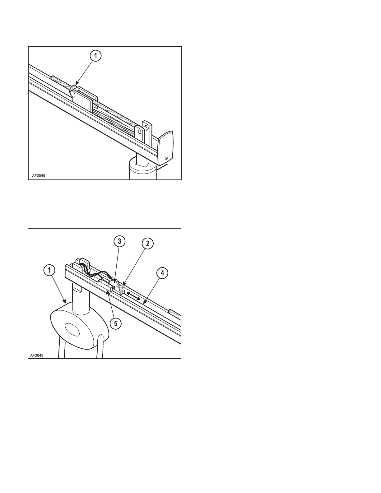
4.11 Flex Arm Tension Adjustment
A. Cover Removal
(1) Disconnect electrical power to the light.
(2) Remove the end cap (1) by removing the phil-
lips head screw (2) (See Figure 4-23)
(3) Slide the arm cover (3) of the end of the flex
arm assembly (4).
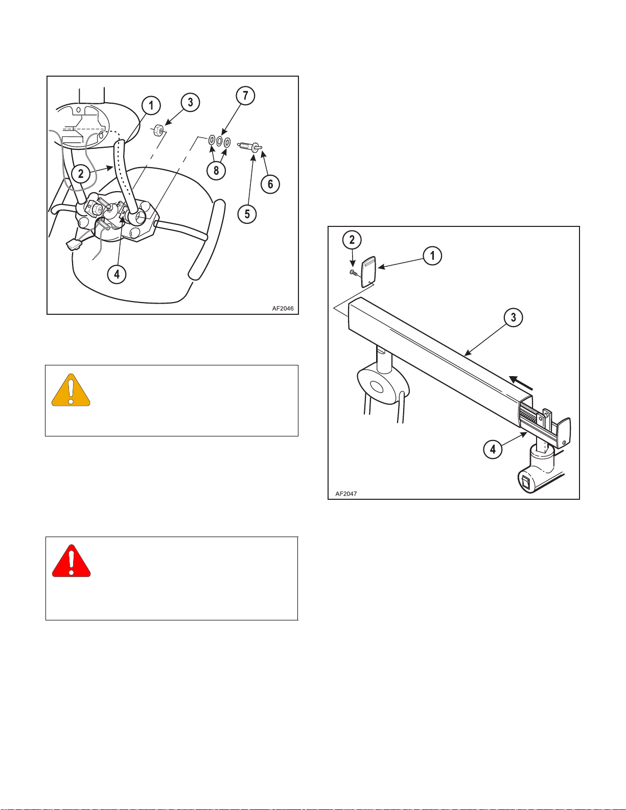
Figure 4-22. Wave Washer replacement
.
EQUIPMENT ALERT
Removing the hardware as described in
this procedure will separate the reflector
assembly from the yoke. Take care to avoid dropping
the reflector.
B. Installation
(1) Working on one side at a time, replace the worn
wave washer (7) with a new wave washer and
re-assemble the pivot stud (5), wire insulator
(6), and flat washers (8) (See Figure 4-22).
WARNING
Make sure the wire insulator is in place
in the pivot stud. This insulator protects
the insulation covering on the gray wire from
wear. F ailure to do so could result in an electrical
hazard.
Figure 4-23. Flex Arm Cover Removal
B. Tension Adjustment
(1) Loosen or tighten the tension adjusting nut (1)
to decrease or increase the tension respectively
until the desired tension if obtained (See Figure
4-24).
(2) Re-assemble the light head by following the
“Remove” procedure in reverse order, but lea v e
the back cover off (Refer to Figures 4-21 and 4-
22).
(3) Adjust the light head rotation (refer to Para
4.9v).
© Midmark Corporation 2000 SF-1618
Page 4-19
(2) Replace the covers by following the “Cover
Removal” procedure in reverse order.
Printed in U.S.A.
Page 44
SECTION IV
Return To Table Of Contents
MAINTENANCE / SERVICE
4.12 Automatic ON/OFF Adjustment
A. Cover Removal
(1) Disconnect electrical power to the light.
(2) Remove the end cap (1) by removing the phil-
lips head screw (2) (See Figure 4-23).
(3) Slide the arm cover (3) of the end of the flex
arm assembly (4).
B. Adjustment
(1) Raise or lower the light head and arm assembly
(1) to the position where the operator would like
the automatic on/off to be activated.(See Figure
4-25).
Figure 4-24. Flex Arm tension Adjustment
Figure 4-25. Auto ON/OFF Adjustment
(2) Loosen the adjustment screw (2) and slide the
limit switch (3) along the rod (4) until it makes
contact with the switch block (5) and the light
turns OFF.
(3) Tighten the adjustment screw (2).
(4) Replace the covers by following the “Cover
Removal” procedure in reverse order.
© Midmark Corporation 2000 SF-1618
Page 4-20
Printed in U.S.A.
Page 45
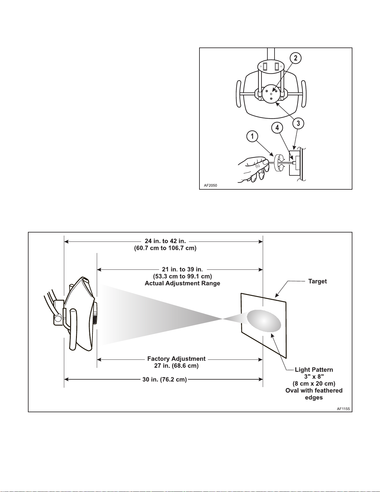
4.13 Light Focus Adjustment
Return To Table Of Contents
(1) Disconnect electrical power to the light.
(2) Position the light 21 to 39 inches (53 to 99cm)
from a target (wall, chair back, etc.) and turn on
the light.
(3) Insert the 9/64" allen wrench (1) into the hole
(2) in the back cover (3) of the light to reach the
focus adjusting screw inside (4) (See Figure 4-
26).
(5) Loosen or tighten the screw until the desired
pattern is obtained. We suggest a nominal pattern size of 3 x 8 inches (8 x 20cm), oval in
shape, with feathered edges (See Figure 4-27).
SECTION IV
MAINTENANCE / SERVICE
Figure 4-26. Light Focus Adjustment
© Midmark Corporation 2000 SF-1618
Figure 4-27. Light Pattern Dimensions
Page 4-21
Printed in U.S.A.
Page 46

SECTION IV
Return To Table Of Contents
MAINTENANCE / SERVICE
© Midmark Corporation 2000 SF-1618
Page 4-22
Printed in U.S.A.
Page 47
SCHEMATICS AND DIAGRAMS
00
Return To Table Of Contents
SECTION V
SCHEMATICS AND DIAGRAMS
SECTION V
5.1 Electrical Schematics / Wiring
Diagrams
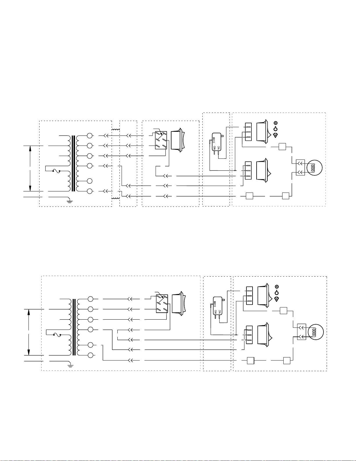
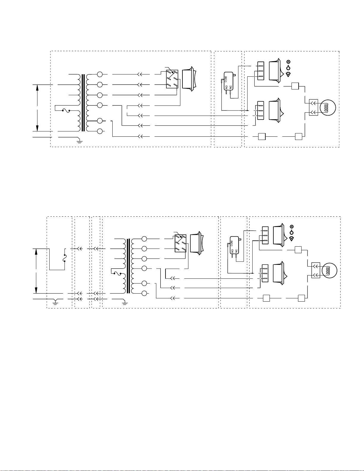
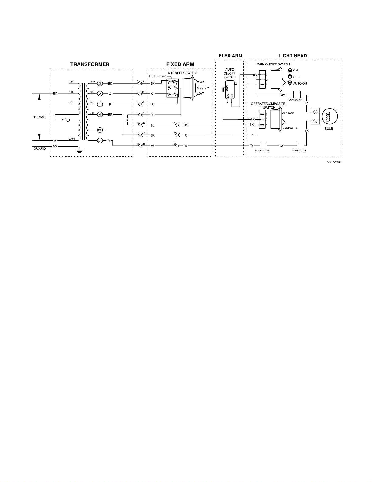
Figures 5-1 thru 5-x illustrates the wiring connections
A.P.C. TRANSFORMER - J BOX
125
115
BK
105
115 VAC
ACC
W
GROUND
G/Y
18.0
3
BK
16.1
O
2
14.1
1
R
9.0
4
BR
C2
C1
W
Unit Mounted Light and Concept LR Light With A.P.C. Transformer
CONSOLE
11 11
22 22
33 33
6 6
BR
55
6 6
W
55
Blue
INTENSITY SWITCH
Jumper
BK
G
R
BR
W
FIXED ARM
5
4
6
Figure 5-1. 120 VAC Wiring Diagram TP1624 Rev B
between the electrical components in the various configurations of the Model L 120 VAC model dental light.
LIGHT HEADFLEX ARM
AUTO
ON/OFF
2
1
3
BL
1
2
3
HIGH
MEDIUM
LOW
BK
R
W
SWITCH
MAIN ON/OFF SWITCH
3
BK
2
1
GY
OPERATE/COMPOSITE
SWITCH
3
2
BK
BK
1
R
W
CONNECTOR CONNECTOR
CONNECTOR
OPERATE
COMPOSITE
GY
ON
OFF
AUTO ON
BK
BK
BULB
KA9224
FIXED ARM UNIVERSAL
Blue Jumper
3
BK
2
G
1
R
4
BL
W
1
BK
2
R
3
W
115 VAC
GROUND
G/Y
125
115
BK
105
ACC
W
18.0
16.1
14.1
9.0
COM
1.3
BK
3
O
2
1
R
4
BR
W
C2
C1
Figure 5-2. 120 VAC Wiring Diagram TP1365 Rev A
Universal Mounted Light
© Midmark Corporation 2000 SF-1618
INTENSITY SWITCH
5
2
4
1
3
6
Page 5-1
HIGH
MEDIUM
LOW
AUTO
ON/OFF
SWITCH
LIGHT HEADFLEX ARM
MAIN ON/OFF SWITCH
3
BK
2
1
GY
OPERATE/COMPOSITE
SWITCH
3
2
BK
BK
1
R
W
CONNECTOR CONNECTOR
CONNECTOR
OPERATE
COMPOSITE
GY
ON
OFF
AUTO ON
BK
BK
BULB
KA922500
Printed in U.S.A.
Page 48
SECTION V
Return To Table Of Contents
SCHEMATICS AND DIAGRAMS
115 VAC
GROUND
115 VAC
GROUND
BK
W
G/Y
TRACK
ASSEMBLY
7.5 AMP
FUSE
125
115
105
ACC
TROLLEY
18.0
16.1
14.1
9.0
COM
1.3
POST
FIXED ARM UNIVERSAL
BK
G
R
W
BK
R
W
INTENSITY SWITCH
5
2
4
1
3
6
HIGH
MEDIUM
LOW
Blue Jumper
BK
3
O
2
1
R
4
BR
W
C2
C1
3
2
1
4
BL
1
2
3
Figure 5-3. 120 VAC Wiring Diagram TP1397 Rev A
Ceiling Mounted Light
FIXED ARM UNIVERSAL
BK
G
R
INTENSITY SWITCH
5
2
4
1
3
6
W
1
BK
2
R
3
W
HIGH
MEDIUM
LOW
125
115
BKBKBK
105
ACC
WWW
G G G
18.0
16.1
14.1
9.0
COM
1.3
Blue Jumper
3
2
1
4
BR
W
C2
C1
AUTO
ON/OFF
SWITCH
ON/OFF
SWITCH
AUTO
LIGHT HEADFLEX ARM
MAIN ON/OFF SWITCH
3
BK
2
1
GY
OPERATE/COMPOSITE
SWITCH
3
2
BK
BK
1
R
W
CONNECTOR CONNECTOR
CONNECTOR
OPERATE
COMPOSITE
GY
LIGHT HEADFLEX ARM
MAIN ON/OFF SWITCH
3
BK
2
1
GY
OPERATE/COMPOSITE
SWITCH
BK
BK
R
W
CONNECTOR CONNECTOR
OPERATE
3
2
1
COMPOSITE
GY
ON
OFF
AUTO ON
ON
OFF
AUTO ON
CONNECTOR
BK
BK
BULB
KA922600
BK
BK
BULB
© Midmark Corporation 2000 SF-1618
Figure 5-4. 120 VAC Wiring Diagram TP1399 Rev A
Track Mounted Light
Page 5-2
Printed in U.S.A.
Page 49
SCHEMATICS AND DIAGRAMS
Return To Table Of Contents
Figure 5-5. 120 VAC Wiring Diagram TP1395 Rev B
Wall/Cabinet Mounted Light
SECTION V
© Midmark Corporation 2000 SF-1618 Page 5-3 Printed in U.S.A.
Page 50

SECTION V
Return To Table Of Contents
SCHEMATICS AND DIAGRAMS
© Midmark Corporation 2000 SF-1618 Printed in U.S.A.
Page 51

SECTION VI
Return To Table Of Contents
PARTS LIST
SECTION VI
PARTS LIST
6.1 Introduction
The illustrated parts list provides information for identifying and ordering the parts necessary to maintain the
unit in peak operating condition. Refer to paragraph 1.5
for parts ordering information.
6.2 Descripti on of Colum ns
The Item column of the parts list gives a component its
own unique number. The same number is given to the
component in the parts illustration. This allows a part
number of a component to be found if the technician
can visually spot the part on the illustration. The technician simply finds the component in question on the illustration and notes the item number of that component.
Then, he finds that item number in the parts list. The
row corresponding to the item number gives the technician the part number, a description of the component,
and quantity of parts per subassembly. Also, if a part
number is known, the location of that component can be
determined by looking for the item number of the component on the illustration.
The Part No. column lists the Knight part number for
that component.
The Description column provides a physical description
of the component.
The Qty . column lists the number of units of a particular
component that is required for the subassembly. The
letters “AR” denote “as required” when quantities of a
particular component cannot be determined, such as:
adhesive.
Bullets { • } in the Part No. column and the Description
column show the indenture level of a component. If a
component does not have a bullet, it is a main component of that illustration. If a component has a bullet, it is
a subcomponent of the next component listed higher in
the parts list than itself that does not have a bullet. Likewise, if a component has two bullets, it is a subcomponent of the next component listed higher in the parts list
than itself that has only one bullet.
6.3 T or que Specifications and Important
Assembly Notes
When specific assembly torque specifications, measurements, or procedures hav e been identified by our
engineering department as required to assure proper
function of the unit, those torque specifications measurements and procedures will be noted on the parts
illustrations. Adherence to these requirements is essential.
© Midmark Corporation 2000 SF-1618 Printed in U.S.A.
Always Specify Model & Serial Number
Page 6-1
Page 52
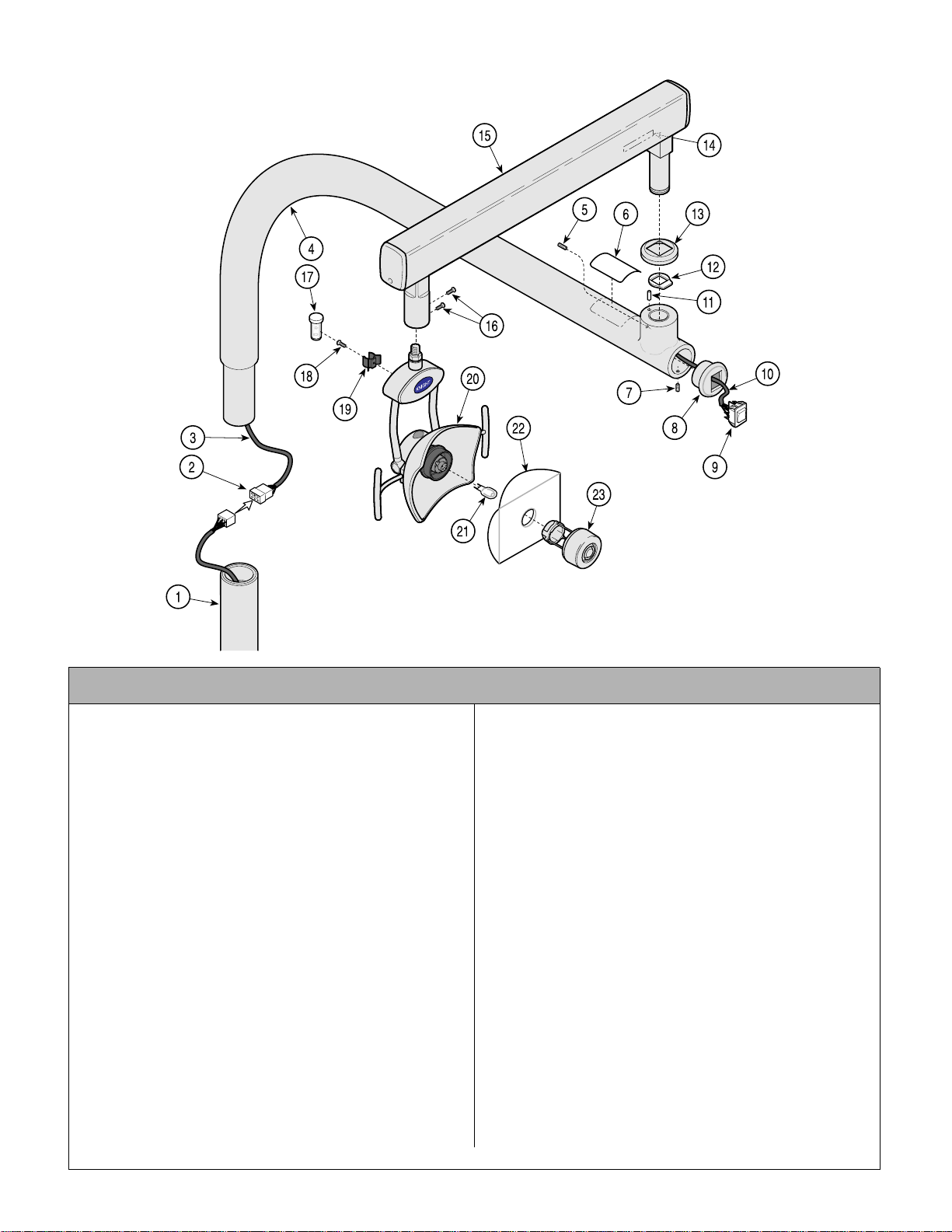
Unit Mounted Light Assembly
Return To Table Of Contents
152924 (120 VAC)
153005 (220 VAC)
SECTION VI
PARTS LIST
NOTE: This model
uses Sterling Grey
painted components.
KA984000i
Used on Units with “LL” Serial Number Prefix
Item Part No. Description Qty. Item Part No. Description Qty.
152924 120 VAC Chair Mounted Light Assembly
(Includes Items 1 thru 27)..................... 1
153005 220 VAC Chair Mounted Light Assembly
(Includes Items 1 thru 27)..................... 1
1 • 152919 • Post Assembly (Refer to “Light Arm
Mounting Component s” El sewhere ) ... 1
2 • 102060 • 6 Circuit Connector.............................1
3 • 152500 • Remote Transformer Cable Assembly 1
4 • 153237 • Light Arm Assembly (Incl. Bearings) .. 1
5 • 122350 • Set Screw (Apply 042- 0024-00,
Loctite)................................................ 1
6 • TPW1376 • Model “L” Rating Plate (120 VAC.)...... 1
• TPW1377 • Model “L” Rating Plate (220 VAC.)... ... 1
7 • 106753 • Set Screw .......................................... 1
8 • 122351-1 • Switch Mounting Cap.......................... 1
9 • 121758 • 3 Position Progressive Rocker Switch
(Apply Loctite #275275)...................... 1
• 152508 • Blue Jumper (Not Shown)................... 1
10 • • Intensity Sw itc h C able Assem bly........ 1
11 • 153024 • Light Stop Pin Kit................................ 1
12 • 121677-2 • Light Arm Stop Washer....................... 1
13 • 053-1223-00 • Rotation Stop Cover ........................... 1
14 • • Serial Nameplate.............................Ref
15 • 152504 • Flex Arm (Refer to “Light Flex Arm
Assembly” Elsewhere)....................... 1
Always Specify Model & Serial Number
16 • 121337-2 • Screw .................................................2
17 • 152507 • Model “L” Spare Bulb ................ ..........1
18 • 122688 • Wood Screw
(Used For Remote Mount) ..................1
19 • 122639 • Spare Bulb Clip ..................................1
20 • 152481 • Light Head (Refer to “Model ‘L’ Light
Head Assembly” Elsewhere)...............1
21 • 121720 • Dental Light Bulb ................................1
22 • 122845 • Model “L” Safety Shield ......................1
23 • 152479 • Lamp Shield Assembly .......................1
24 • TPW1376 • 120 VAC Remote Transformer Wir i ng
Diagram (Note Shown)........................1
• TPW1364 • 220 VAC Remote Transformer Wir i ng
Diagram (Note Shown)........................1
25 • 153012 • 120 V. Light Transformer Assembly
(Not Shown)........................................1
• • 220 V. Light Transformer Assembly
(Not Shown)........................................1
26 • TP1624 • 120 VAC Curved Arm Wiring Dia gram
Diagram (Note Shown)........................1
• TP1625 • 220 VAC Curved Arm Wiring Dia gram
Diagram (Note Shown)........................1
© Midmark Corporation 2000 SF-1618 Printed in U.S.A.
Rev. 5/03
Page 6-2
Page 53
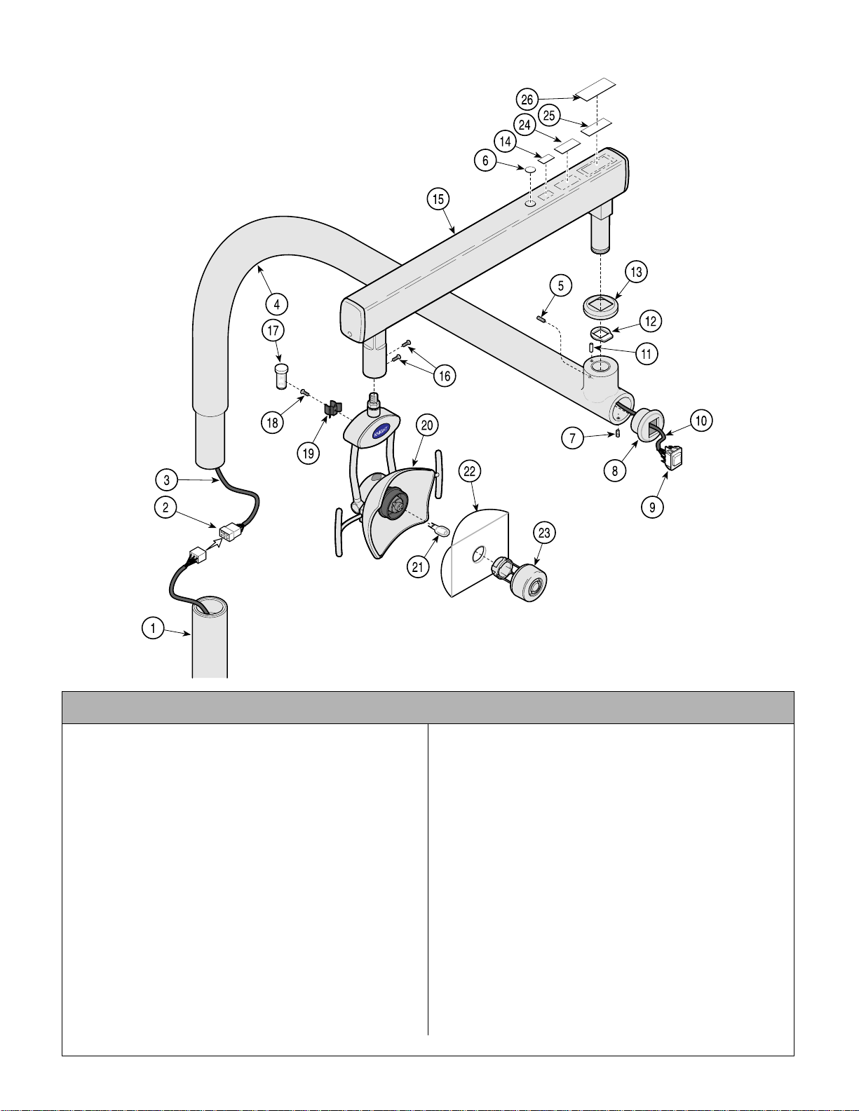
Unit Mounted Light Assembly
Return To Table Of Contents
152924-01 (120 VAC)
153005-01 (220 VAC)
SECTION VI
PARTS LIST
NOTE: This model
uses Pebble Grey
painted components.
KA984001i
Used on Units with “PH” Serial Number Prefix
Item Part No. Description Qty. Item Part No. Description Qty.
152924-01 120 VAC Chair Mounted Light Assembly
(Includes Items 1 thru 27)..................... 1
153005-01 220 VAC Chair Mounted Light Assembly
(Includes Items 1 thru 27)..................... 1
1 • 15291 9-01 • Post Assembly (Refer to “Light Arm
Mounting Component s” Elsewhere) ... 1
2 • 10206 0 • 6 Circuit Connector............................. 1
3 • 15250 0 • Remote Transformer Cable Assembly 1
4 • 15323 7-01 • Light Arm Assembly (Incl. Bearings) .. 1
5 • 12235 0 • Set Screw (Apply 042-0024-00,
Loctite)................................................ 1
6 • 061-0652-00 • Type B Label....................................... 1
7 • 10675 3 • Set Screw .......................................... 1
8 • 12235 1-50 • Switch Mounting Cap.......................... 1
9 • 12175 8 • 3 Position Progressive Rocker Switch
(Apply Loctite #275275)...................... 1
• 152508 • Blue Jumper (Not Shown)................... 1
10 • • Intensity Switch Cable Assembly........ 1
11 • 153024 • Light Stop Pin Kit................................1
Always Specify Model & Serial Number
12 • 121677-2 • Light Arm Stop Washer.......................1
13 • 053-1223-01 • Rotation Stop Cover............................1
14 • 061-0665-00 • CE Label .............................................1
15 • 152504-01 • Flex Arm (Refer to “Light Fl ex Arm
Assembly” Elsewhere).........................1
16 • 121337-2 • Screw .................................................2
17 • 152507 • Model “L” Spare Bulb ..........................1
18 • 122688 • Wood Screw
(Used For Remote Mount) ..................1
19 • 122639 • Spare Bulb Clip ..................................1
20 • 152481-01 • Li ght Head (Refer to “Model ‘L’ Light
Head Assembly” Elsewhere)...............1
21 • 121720 • Dental Light Bulb ...................... ..........1
22 • 122845 • Model “L” Safety Shield ......................1
23 • 152479-01 • Lamp Shield Assembly .......................1
24 ••ETL Label....................................... Ref
25 ••Serial Number Label ......................Ref
26 • 061-0741-00 • Clear Laminate (To Cover S/N Label) .1
© Midmark Corporation 2000 SF-1618 Printed in U.S.A.
Rev. 5/03
Page 6-3
Page 54
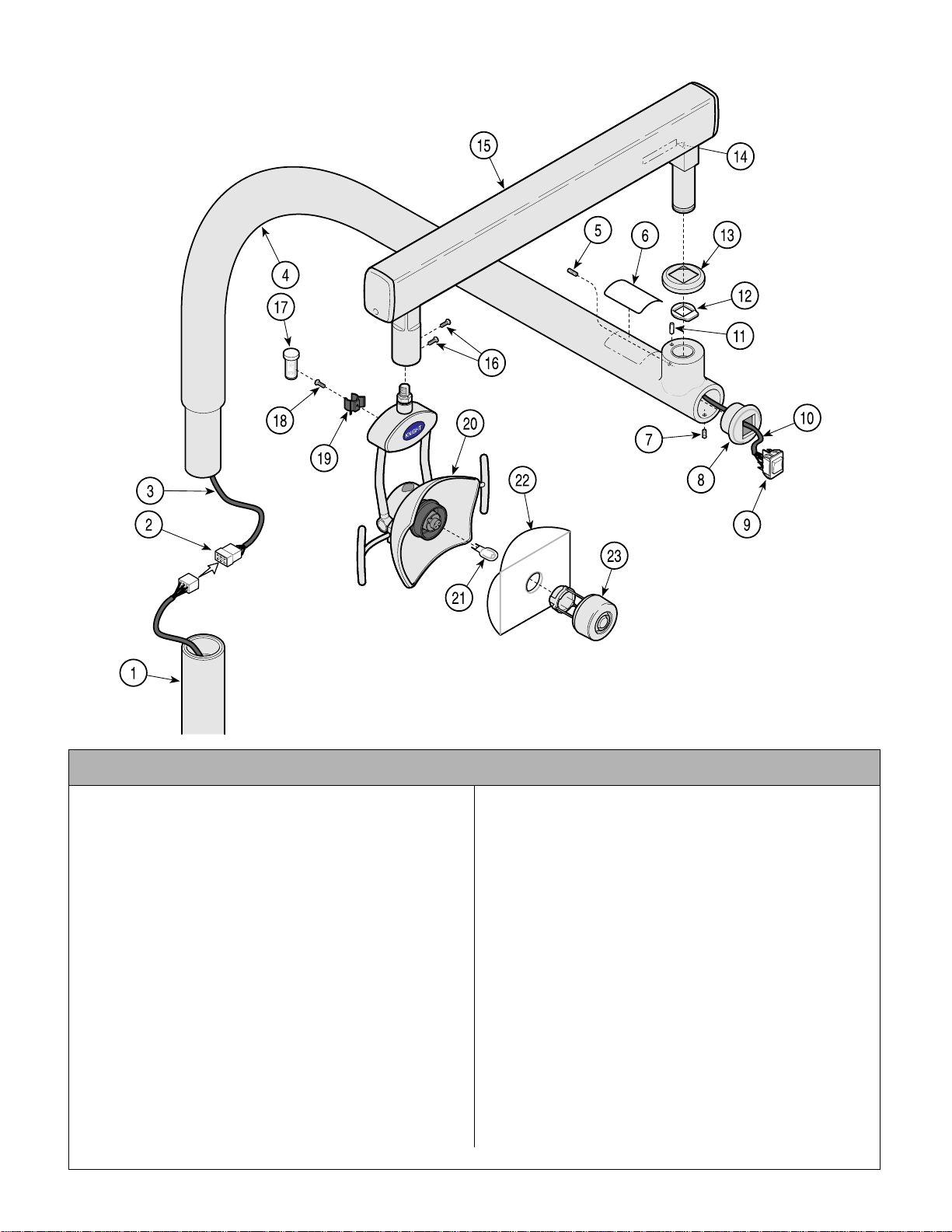
Concept LR Assembly 153144
Return To Table Of Contents
SECTION VI
PARTS LIST
NOTE: This model
uses Sterling Grey
painted components.
KA984000i
Used on Units with “LL” Serial Number Prefix
Item Part No. Description Qty. Item Part No. Description Qty.
153144 Concept LR Light Assembly
(Includes Items 1 thru 27)..................... 1
• 153122 • Light Arm Asse m bly (Refer to “Light
Arm Mounting Co m ponents”
Elsewhere).......................................... 1
2 • 10206 0 • 6 Circuit Connector............................. 1
3 • 15250 0 • Remote Transformer Cable Assembly 1
4 • 15323 7 • Light Arm Assembly (Incl. Bearings) .. 1
5 • 12235 0 • Set Screw (Apply 042-0024-00,
Loctite)................................................ 1
6 • TPW1376 • Model “L” Rating Plate (120 VAC.) ...... 1
7 • 10675 3 • Set Screw .......................................... 1
8 • 12235 1-1 • Switch Mounting Cap.......................... 1
9 • 12175 8 • 3 Position Progressive Rocker Switch
(Apply Loctite #275275)...................... 1
• 152508 • Blue Jumper (Not Shown)................... 1
10 • • Intensity Switch Cable Assembly........ 1
11 • 153024 • Light Stop Pin Kit................................1
12 • 121677-2 • Light Arm Stop Washer....................... 1
13 • 122307-1 • Rotation Stop Cover........................... 1
Always Specify Model & Serial Number
14 • • Serial Nameplate............................. Ref
15 • 152504 • Flex Arm (Refer to “Light Fl ex Arm
Assembly” Elsewhere)........................1
16 • 121337-2 • Screw .................................................2
17 • 152507 • Model “L” Spare Bulb ..........................1
18 • 122688 • Wood Screw
(Used For Remote Mount) ..................1
19 • 122639 • Spare Bulb Clip ..................................1
20 • 152481 • Light Head ( Refer to “Model ‘L’ Light
Head Assembly” Elsewhere)...............1
21 • 121720 • Dental Light Bulb ...................... ..........1
22 • 122845 • Model “L” Safety Shield ......................1
23 • 152479 • Lamp Shield Assembly .......................1
24 • TPW1376 • 120 VAC Remote Transformer Wir i ng
Diagram (Note Shown)........................1
25 • 153012 • 120 V. Light Transformer Assembly
(Not Shown)........................................1
26 • TP1624 • 12 0 VAC Curved Arm Wiring Diagram
Diagram (Note Shown)........................1
© Midmark Corporation 2000 SF-1618 Printed in U.S.A.
Rev. 5/03
Page 6-4
Page 55
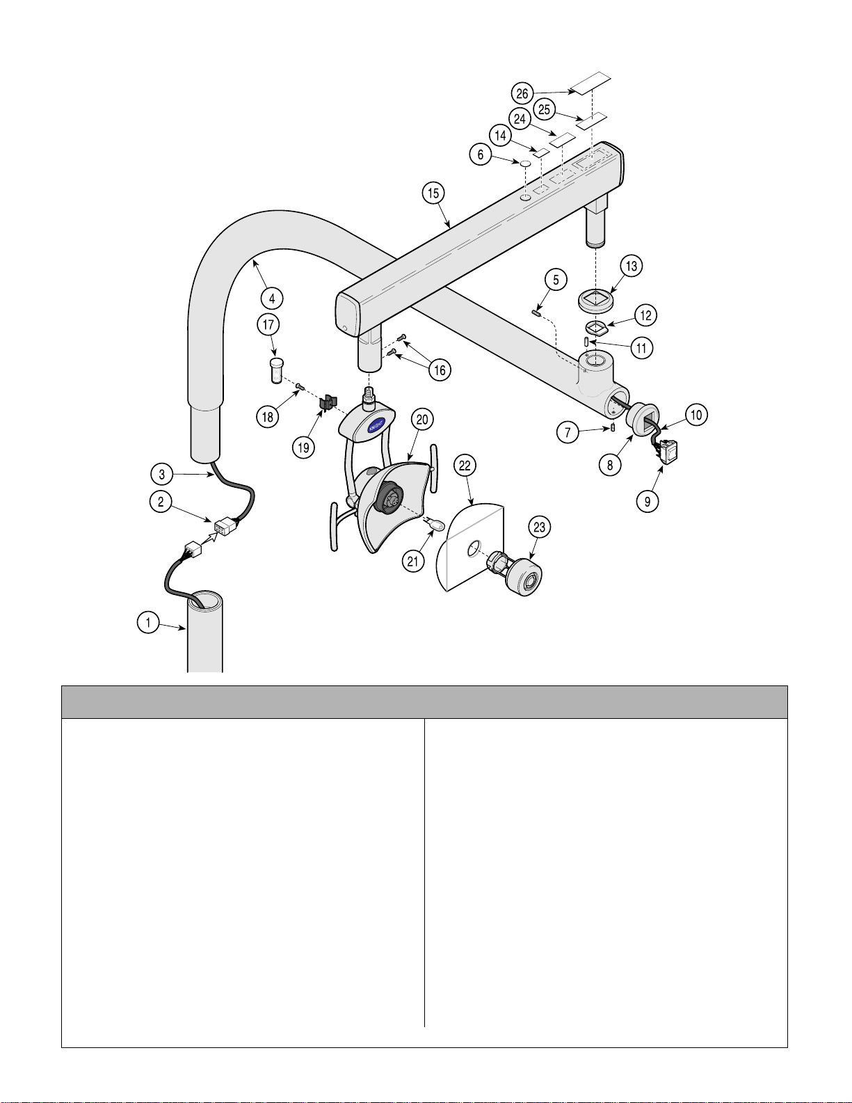
Concept LR Assembly 153144-01
Return To Table Of Contents
SECTION VI
PARTS LIST
NOTE: This model
uses Pebble Grey
painted components.
KA984001i
Used on Units with “PH” Serial Number Prefix
Item Part No. Description Qty. Item Part No. Description Qty.
153144-01 Concept LR Light Assembly
(Includes Items 1 thru 27)..................... 1
• 153122-01 • Light Arm Assem bly (Re fer to “Light
Arm Mounting Co m ponents”
Elsewhere).......................................... 1
2 • 10206 0 • 6 Circuit Connector............................. 1
3 • 15250 0 • Remote Transformer Cable Assembly 1
4 • 15323 7-01 • Light Arm Assembly (Incl. Bearings) .. 1
5 • 12235 0 • Set Screw (Apply 042-0024-00,
Loctite)................................................ 1
6 • 061-0652-00 • Type B Label....................................... 1
7 • 10675 3 • Set Screw .......................................... 1
8 • 12235 1-50 • Switch Mounting Cap.......................... 1
9 • 12175 8 • 3 Position Progressive Rocker Switch
(Apply Loctite #275275)...................... 1
• 152508 • Blue Jumper (Not Shown)................... 1
10 • • Intensity Switch Cable Assembly........ 1
11 • 153024 • Light Stop Pin Kit................................1
12 • 121677-2 • Light Arm Stop Washer....................... 1
Always Specify Model & Serial Number
13 • 122307-50 • Rotation Stop Cover............................1
14 • 061-0665-00 • CE Label ......................................... Ref
15 • 152504-01 • Flex Arm (Refer to “Light Flex Arm
Assembly” Elsewhere)........................1
16 • 121337-2 • Screw .................................................2
17 • 152507 • Model “L” Spare Bulb ..........................1
18 • 122688 • Wood Screw
(Used For Remote Mount) ..................1
19 • 122639 • Spare Bulb Clip ..................................1
20 • 152481-01 • Li ght Head (Refer to “Model ‘L’ Light
Head Assembly” Elsewhere)...............1
21 • 121720 • Dental Light Bulb ...................... ..........1
22 • 122845 • Model “L” Safety Shield ......................1
23 • 152479-01 • Lamp Shield Assembly .......................1
26 ••ETL Label........................................ Ref
27 ••Serial Number Label .......................Ref
28 • 061-0741-00 • Clear Laminate (To Cover S/N Label) .1
© Midmark Corporation 2000 SF-1618 Printed in U.S.A.
Rev. 5/03
Page 6-5
Page 56
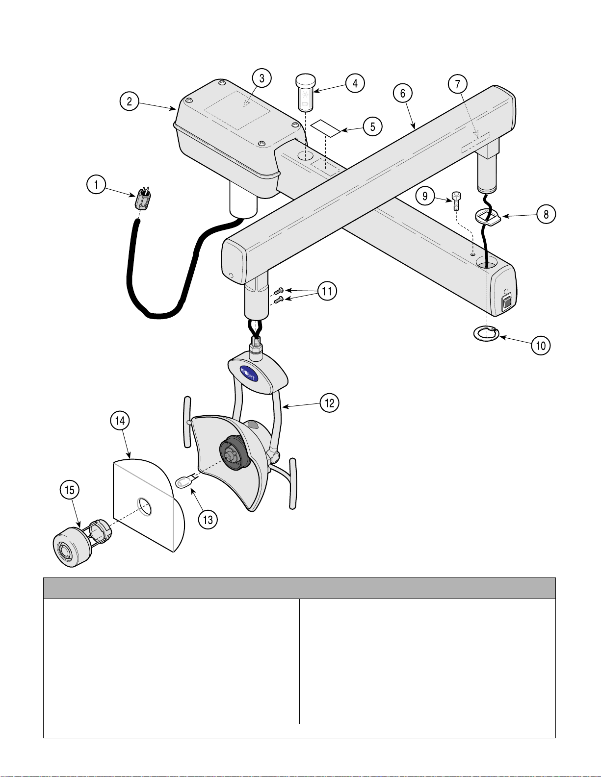
Universal Mounted Light Assembly
Return To Table Of Contents
152480
SECTION VI
PARTS LIST
NOTE: This model
uses Sterling Grey
painted components.
AF202600i
Used on Units with “ LL” Serial Number Prefix
Item Part No. Description Qty. Item Part No. Description Qty.
152480 Model “L” 120 VAC Universal Light
Assembly (Includes Items 1 thru 15) ..... 1
1 • 11099 4 • 120 VAC power cord Plug...................1
2 • 15248 2 • 120 VAC Fixed Arm (Refer to “Universal
Light Fixed Arm Assy” Elsewhere)...... 1
3 • TP1365 • 120 VAC Wiring Diagram.................... 1
4 • 15250 7 • Model “L” Spare Bulb ..........................1
5 • TP1376 • 120 VAC Model “L” Rating Plate ......... 1
6 • 15250 4 • Flex Arm Assy (Refer to “Light Flex
Arm Assy” Elsewhere)........................ 1
Always Specify Model & Serial Number
7 • • Serial Nameplate.............................Ref
8 • 12167 7-2 • Light Arm Stop Washer.......................1
9 • 11763 6 • Stop Rotation Screw Assembly........... 1
10 • 110065 • Retaining Ring.....................................1
11 • 121337-2 • Screw..................................................2
12 •152481 • Light He ad ( R efer to “Model ‘L’ Light
Head Assembly” Elsewhere)...............1
13 •121720 • Dental Light Bulb ......................... .......1
14 •122845 • Model “L” Safety Shield ......................1
15 •152479 • Lamp Shield Assembly ....................... 1
© Midmark Corporation 2000 SF-1618 Printed in U.S.A.
Rev. 6/01
Page 6-6
Page 57
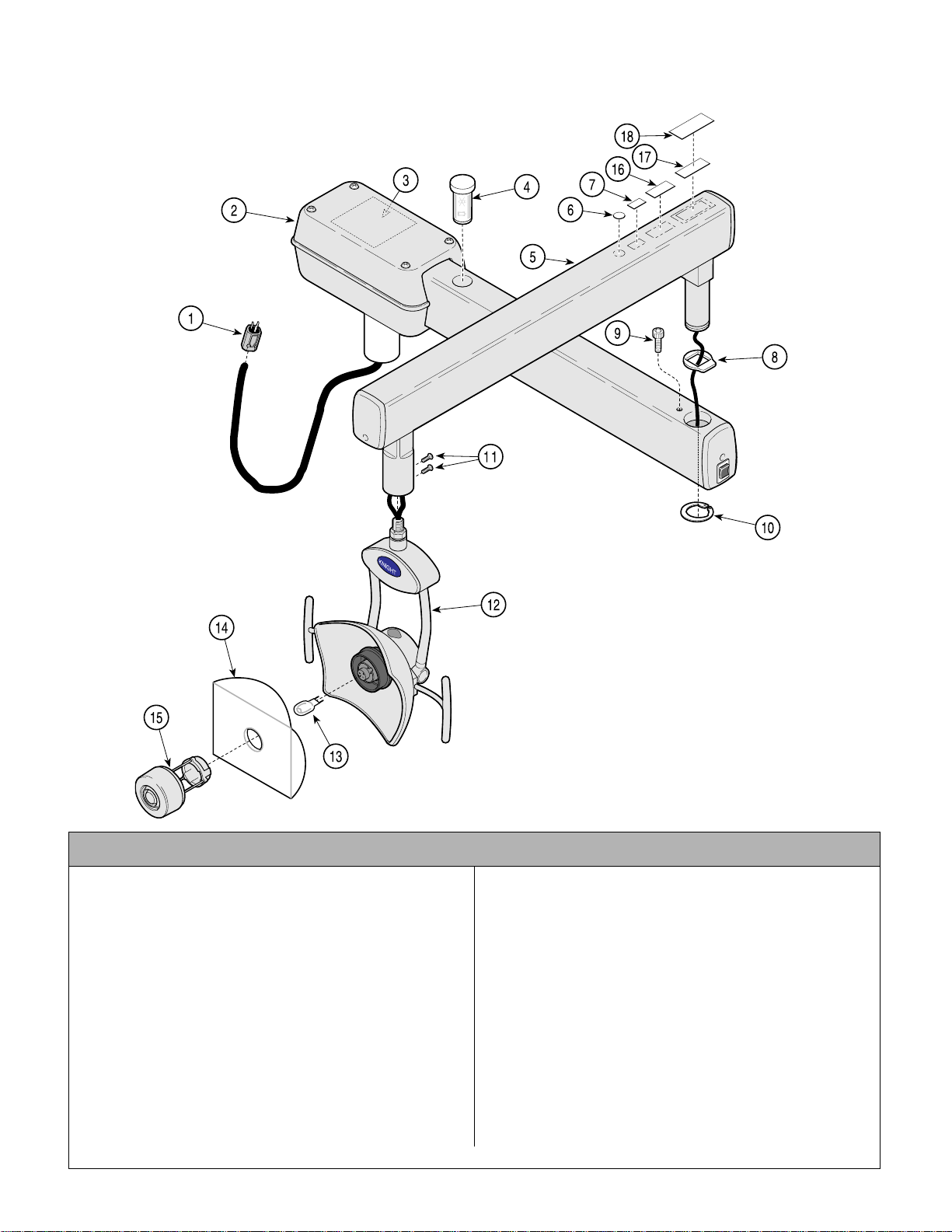
Universal Mounted Light Assembly
Return To Table Of Contents
SECTION VI
PARTS LIST
152480-01 (120VAC) & 152577-01 (220 VAC)
NOTE: This model
uses Pebble Grey
painted components.
AF202601i
Used on Units with “ PH” Serial Number Prefix
Item Part No. Description Qty. Item Part No. Description Qty.
152480-01 Model “L” 120 VAC Universal Light
Assembly (Includes Items 1 thru 15) ..... 1
152577-01 Model “L” 220 VAC Universal Light Assm.
(Includes Items 1 thru 15 & ) ................. 1
1 • 11099 4 • Power Cord Plug (120 VAC) ............... 1
• 120374 • Power Cord Plug (220 VAC) ............... 1
2 • 15248 2-01 • 120 VAC Fixed Arm (Refer to “Universal
Light Fixed Arm Assy” Elsewhere)...... 1
• 152591-01 • 220 VAC Fixed Arm (Refer to “Universal
Light Fixed Arm Assy” Elsewhere)...... 1
3 • TP1365 • Wiring Diagram (120 VAC).................. 1
• TP1406 • Wiring Diagram (220 VAC).................. 1
4 • 15250 7 • Model “L” Spare Bulb ..........................1
5 • 15250 4-01 • Flex Arm Assy (Refer to “Light Flex
Arm Assy” Elsewhere)........................ 1
Always Specify Model & Serial Number
6 • 061-0652-00 • Type B Label .......................................1
7 • 061-0665-00 • CE Label .............................................1
8 • 12167 7-2 • Light Arm Stop Washer.......................1
9 • 11763 6 • Stop Rotation Screw Assembly........... 1
10 • 110065 • Retaining Ring.....................................1
11 • 121337-2 • Screw..................................................2
12 •152481-01 • Light Head (Refer to “Model ‘L’ Light
Head Assembly” Elsewhere)...............1
13 •121720 • Dental Light Bulb ......................... .......1
14 •122845 • Model “L” Safety Shield ......................1
15 •152479-01 • Lamp Shield Assembly .......................1
16 ••ETL Label........................................ Ref
17 •061-0785-00 • Serial Number Label ...........................1
18 • 061-0741-00 • Clear Laminate (To Cover S/N Label) .1
© Midmark Corporation 2000 SF-1618 Printed in U.S.A.
Rev. 6/01
Page 6-7
Page 58
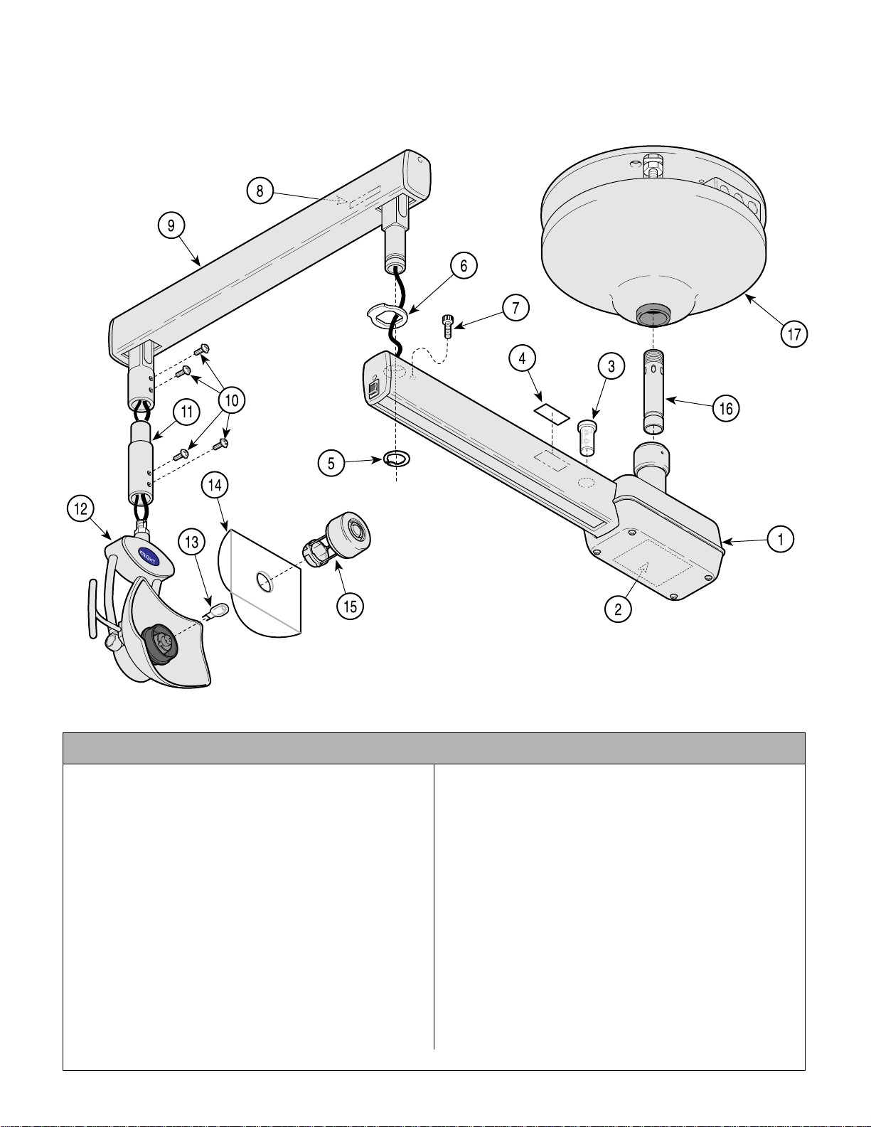
Ceiling Mounted Light Assembly
Return To Table Of Contents
152567
SECTION VI
PARTS LIST
NOTE: This model
uses Sterling Grey
painted components.
AF203600
Used on Units with “ LL” Serial Number Prefix
Item Part No. Description Qty. Item Part No. Description Qty.
152567 120 VAC Ceiling Mount ed Light
Assembly (Includes Items 1 thru 15) ..... 1
1 • 15248 2 • 120 VAC Fixed Arm (Refer to “Ceiling
Light Fixed Arm Assy” Elsewhere)...... 1
2 • TP1397 • 120 VAC Wiring Diagram.................... 1
3 • 15250 7 • Model “L” Spare Bulb ..........................1
4 • TP1376 • 120 VAC Model “L” Rating Plate ......... 1
5 • 11006 5 • Retaining Ring.................................... 1
6 • 12167 7-2 • Light Arm Stop Washer....................... 1
7 • 15278 6 • Stop Rotation Screw Assembly .......... 1
8 • • Serial Nameplate.............................Ref
9 • 15250 4 • Flex Arm Assy (Refer to “Light Flex
Arm Assy” Elsewhere)........................ 1
10 • 121337-2 • Screw.................................................. 4
11 • 121843-1 • Light Post Extensio n ........................... 1
12 • 152481 • Light He ad ( R efer to “Model ‘L’ Light
Head Assembly” Elsewhere) .............. 1
Always Specify Model & Serial Number
13 • 121720 • Dental Light Bulb ...................... ..........1
14 • 122845 • Model “L” Safety Shield ......................1
15 • 152479 • Lamp Shield Assembly .......................1
16 152581 7 in. Suspension Tube (7'8"/7/11") ........1
15 258 2 11 in. Suspension Tube (8'0"/8'3”) ........1
152583 15 in. Suspension Tube (8'4"/8'7") ........1
15 258 4 19 in. Suspension Tube (8'8"/8'11") ......1
152585 23 in. Suspension Tube (9'0"/9'3") ........1
152586 27 in. Suspension Tube (9'4"/9'7") ........1
15 258 7 31 in. Suspension Tube (9'8"/9'11") ......1
15 258 8 35 in. Suspension Tube (10'0"/10'3") ....1
15 258 9 39 in. Suspension Tube (10'4"/10'7") ....1
15 259 0 43 in. Suspension Tube (10'8"/11'0") ....1
17 • 149918 • Tripod Assembly (Refer to “Tripod
Assembly” Elsewhere).........................1
© Midmark Corporation 2000 SF-1618 Printed in U.S.A.
Page 6-8
Page 59
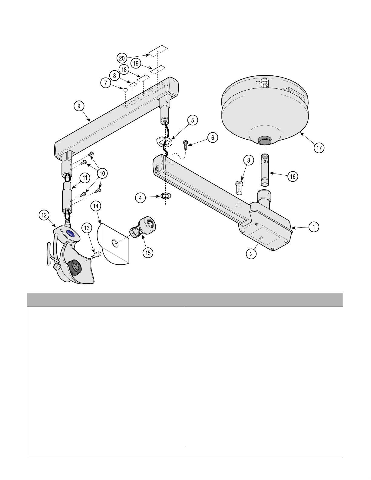
Ceiling Mounted Light Assembly
Return To Table Of Contents
SECTION VI
PARTS LIST
152567-01 (120 VAC) & 152568-01 (220 VAC)
NOTE: This model
uses Pebble Grey
painted components.
AF203601i
Used on Units with “ PH” Serial Number Prefix
Item Part No. Description Qty. Item Part No. Description Qty.
152567-01 120 VAC C eil i ng M ounted Light Assembly
(Includes Items 1 thru 15 & 17) ............. 1
152568-01 220 VAC C eil i ng M ounted Light Assembly
(Includes Items 1 thr u 15 & 17 thru 19). 1
1 • 15256 6-01 • 120 VAC Fixed Arm (Refer to “Ceiling
Light Fixed Arm Assy” Elsewhere)...... 1
• 152592-01 • 220 VAC Fixed Arm (Refer to “Ceiling
Light Fixed Arm Assy” Elsewhere)...... 1
2 • TP1397 • 120 VAC Wiring Diagram.................... 1
• TP1398 • 220 VAC Wiring Diagram.................... 1
3 • 15250 7 • Model “L” Spare Bulb ..........................1
4 • 11006 5 • Retaining Ring.................................... 1
5 • 12167 7-2 • Light Arm Stop Washer....................... 1
6 • 15278 6 • Stop Rotation Screw Assembly .......... 1
7 • 061-0652-00 • Type B Label....................................... 1
8 • 061-0665-00 • CE Label ............................................. 1
9 • 15250 4-01 • Flex Arm Assy (Refer to “Light Flex
Arm Assy” Elsewhere)........................ 1
10 • 121337-2 • Screw.................................................. 4
11 • 121843-50 • Light Post Extension........................... 1
Always Specify Model & Serial Number
12 • 152481-01 • Li ght Head (Refer to “Model ‘L’ Li ght
Head Assembly” Elsewhere)...............1
13 • 121720 • Dental Light Bulb ...................... ..........1
14 • 122845 • Model “L” Safety Shield ......................1
15 • 152479-01 • Lamp Shield Assembly .......................1
16 152581-01 7 in. Suspension Tube (7'8"/7/11") ........1
15 258 2-01 11 in. Suspension Tube (8'0"/8'3”) ........1
152583-01 15 in. Suspension Tube (8'4"/8'7") ........1
15 258 4-01 19 in. Suspension Tube (8'8"/8'11 ") ......1
152585-01 23 in. Suspension Tube (9'0"/9'3") ........1
152586-01 27 in. Suspension Tube (9'4"/9'7") ........1
15 258 7-01 31 in. Suspension Tube (9'8"/9'11 ") ......1
15 258 8-01 35 in. Suspension Tube (10'0"/1 0' 3") ....1
15 258 9-01 39 in. Suspension Tube (10'4"/1 0' 7") ....1
15 259 0-01 43 in. Suspension Tube (10'8"/1 1' 0") ....1
17 • 149918-01 • Tripod Assembly (Refer to “Tripod
Assembly” Elsewhere).........................1
18 ••ETL Label........................................ Ref
19 ••Serial Number Label .......................Ref
20 • 061-741-00 • Clear Laminate (To Cover S/N Label) .1
© Midmark Corporation 2000 SF-1618 Printed in U.S.A.
Rev. 6/01
Page 6-9
Page 60
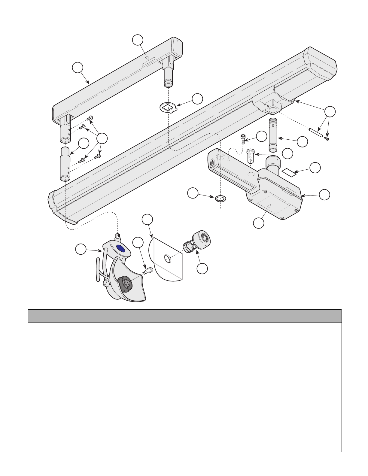
Track Mounted Light Assembly
Return To Table Of Contents
SECTION VI
PARTS LIST
152571
8
9
6
17
11
10
7
16
1
2
5
3
12
KNIGHT
14
13
4
NOTE: This model
15
uses Sterling Grey
painted components.
Used on Units with “ LL” Serial Number P refix
Item Part No. Description Qty. Item Part No. Description Qty.
152571 120 VAC Track Mou nt ed Light
Assembly (Includes Items 1 thru 15)......1
1 • 152 507 • Model “L” Spare Bulb ...........................1
2 • TP1376 • 120 VAC Model “L” Rating Plate ..........1
3 • 152 576 • 120 VAC Fixed Arm (Refer to “Track
Light Fixed Arm Assy” Elsewhere).......1
4 • TP1399 • 120 VAC Wiring Diagram.....................1
5 • 110 065 • Retaining Ring .....................................1
6 • 121 861-2 • Light Arm Stop Washer........................1
7 • 152 786 • Stop Rotation Screw Assembly ...........1
8 • • Serial Nameplate................ .............Ref
9 • 152 504 • Flex Arm Assy (Refer to “Light Flex
Arm Assy” Elsewhere).........................1
10 • 121337-2 • Screw...................................................4
11 • 121843-1 • Light Post Exten sion ............................1
12 • 152481 • Light Head (Refer to “Model ‘L’ Light
Head Assembly” Elsewhere) ...............1
Always Specify Model & Serial Number
13 • 121720 • Dental Light Bulb ................................1
14 • 122845 • Model “L” Safety Shie ld ......................1
15 • 152479 • Lamp Shield Assembly ....................... 1
16 152581 7 in. Suspension Tube (7'8"/7/11") ........1
152 58 2 11 in. Suspension Tube (8'0"/8'3”) ........1
152583 15 in. Suspension Tube (8'4"/8'7") ........1
152 58 4 19 in. Suspension Tube (8'8"/8'11") ......1
152585 23 in. Suspension Tube (9'0"/9'3") ........1
152586 27 in. Suspension Tube (9'4"/9'7") ........1
152 58 7 31 in. Suspension Tube (9'8"/9'11") ......1
152 58 8 35 in. Suspension Tube (10'0"/10'3") ....1
152 58 9 39 in. Suspension Tube (10'4"/10'7") ....1
152 59 0 43 in. Suspension Tube (10'8"/11'0") ....1
17 • 152603 • 120 VAV Track/Trolley (Refer to “Track/
Trolley Assembly” Elsewhere).............1
AF2035
© Midmark Corporation 2000 SF-1618 Printed in U.S.A.
Page 6-10
Page 61

Track Mounted Light Assembly
Return To Table Of Contents
SECTION VI
PARTS LIST
152571-01 (120 VAC) & 152572-01 (220 VAC)
NOTE: This model
uses Pebble Grey
painted components.
Used on Units with “ PH” Serial Number Prefix
Item Part No. Description Qty. Item Part No. Description Qty.
152571-01 120 VAC Track Mounted Light
Assembly (Includes Items 1 thru 15)......1
152572-01 220 VAC Track Mounted Light
Assembly (Includes Items 1 thru 15)......1
1 • 152 507 • Model “L” Spare Bulb ...........................1
2 • 152 576-01 • 120 VAC Fixed Arm (Refer to “Track
Light Fixed Arm Assy” Elsewhere).......1
• 152612-01 • 220 VAC Fixed Arm (Refer to “Track
Light Fixed Arm Assy” Elsewhere).......1
3 • TP1399 • 120 VAC Wiring Diagram.....................1
• TP1400 • 220 VAC Wiring Diagram.....................1
4 • 110 065 • Retaining Ring .....................................1
5 • 121 861-2 • Light Arm Stop Washer........................1
6 • 152 786 • Stop Rotation Screw Assembly ...........1
7 • 061 -0652-00 • Type B Label........................................1
8 • 061 -0665-00 • CE Label ..............................................1
9 • 152 504-01 • Flex Arm Assy (Refer to “Light Flex
Arm Assy” Elsewhere).........................1
10 • 121337-2 • Screw...................................................4
11 • 121843-50 • Light Post Extension............................1
12 • 152481-01 • Light Head (Refer to “Model ‘L’ Light
Head Assembly” Elsewhere) ...............1
Always Specify Model & Serial Number
13 • 121720 • Dental Light Bulb ................................1
14 • 122845 • Model “L” Safety Shie ld ......................1
15 • 152479-01 • Lamp Shield Assembly ....................... 1
16 152581-01 7 in. S uspension Tube (7 '8"/7/11") ........1
152 58 2-01 11 in. Suspension Tube (8'0"/8'3”) ........1
152583-01 15 in. Suspension Tube (8'4"/8'7") ........ 1
152 58 4-01 19 in. Suspension Tube (8'8"/8'11") ......1
152585-01 23 in. Suspension Tube (9'0"/9'3") ........ 1
152586-01 27 in. Suspension Tube (9'4"/9'7") ........ 1
152 58 7-01 31 in. Suspension Tube (9'8"/9'11") ......1
152 58 8-01 35 in. Suspension Tube (10'0"/10 '3 ") ....1
152 58 9-01 39 in. Suspension Tube (10'4"/10 '7 ") ....1
152 59 0-01 43 in. Suspension Tube (10'8"/11 '0 ") ....1
17 • 152603-01 • 120 VAV Track/Trolley (Refer to “Track/
Trolley Assembly” Elsewhere).............1
• 152609-01 • 220 VAV Track/Trol l ey (Refer to “Track/
Trolley Assembly” Elsewhere).............1
18 ••ETL Label........................................ Ref
19 ••Serial Number Label ....................... Ref
20 • 061-0741-00 • Clear Laminate (To Cover S/N Lab el ) .1
AF2035
© Midmark Corporation 2000 SF-1618 Printed in U.S.A.
Page 6-11
Page 62
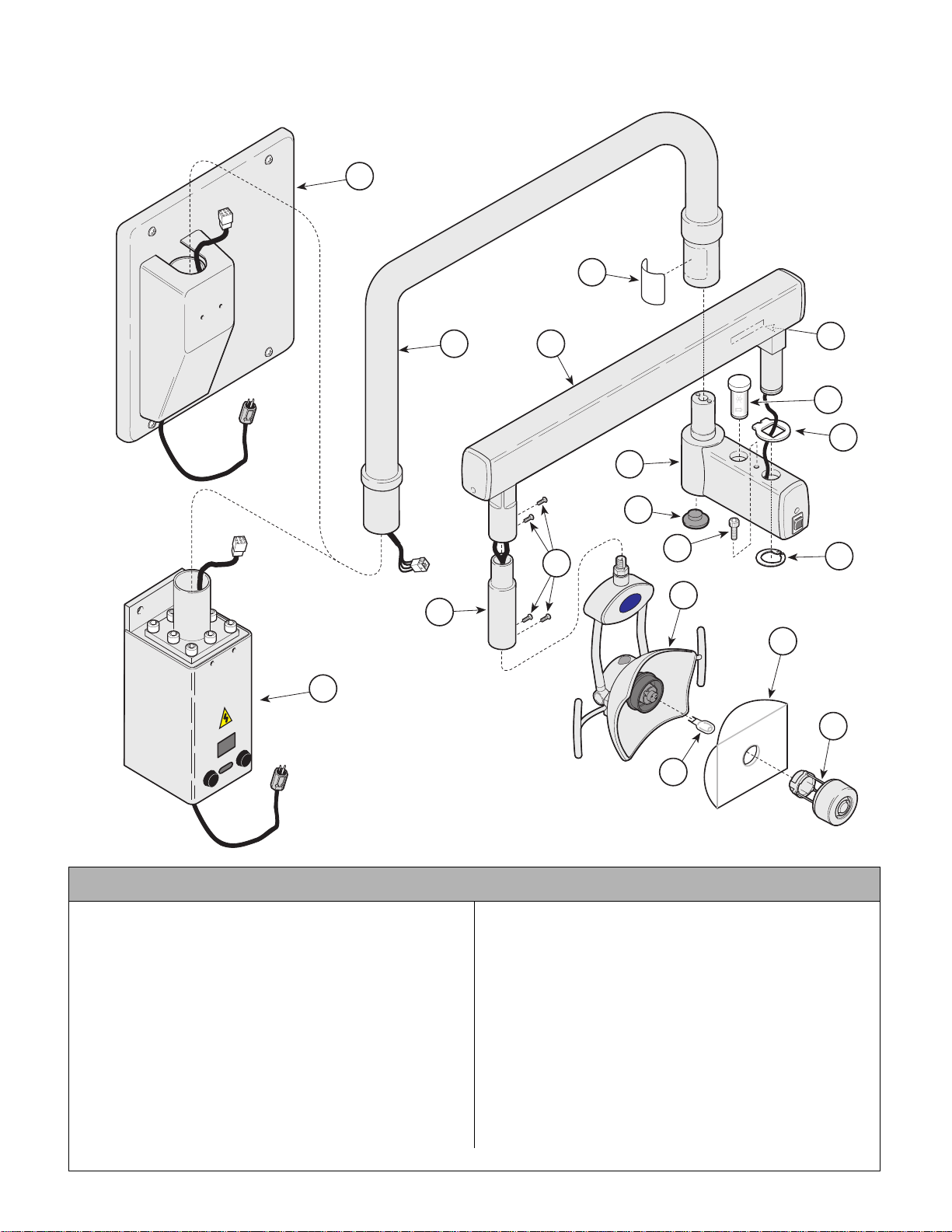
Wall/Cabinet Mounted Light Assembly
Return To Table Of Contents
(Long Arm) 152686
18
3
SECTION VI
PARTS LIST
17
2
12
NOTE: This model
uses Sterling Grey
painted components.
4
11
8
KNIGHT
5
6
7
1
10
9
13
15
16
14
Used on Units with “ LL” Serial Number Prefix
Item Part No. Description Qty. Item Part No. Description Qty.
152686 120 VAC wall/Cabinet M ounted Light
Assembly (Includes Items 1 thru 16) ..... 1
1 • 12176 8-1 • Hole Plug............................................ 1
2 • 15306 8 • Light Post Assembly .......................... 1
3 • TP1376 • 120 VAC Model “L” Rating Plate ........ 1
4 • 15250 4 • Flex Arm Assy (Refer to “Light Flex
Arm Assy” Elsewhere)........................ 1
5 • • Serial Nameplate.............................Ref
6 • 15250 7 • Model “L” Spare Bulb .........................1
7 • 12186 1-2 • Locking Wa sher ................................. 1
8 • 15268 4 • Fixed Arm As sy ( Refer to “Ligh t Fixed
Arm Assy” Elsewhere)........................ 1
9 • 11006 5 • Retaining Ring.................................... 1
© Midmark Corporation 2000 SF-1618 Printed in U.S.A.
AF2029
10 • 152786 • Stop Rotation Screw Assembly...........1
11 • 121337-2 • Screw .................................................4
12 • 121843-1 • Light Post Extension ...........................1
13 • 152481 • Light Head ( Refer to “Model ‘L’ Light
Head Assembly” Elsewhere)...............1
14 • 121720 • Dental Light Bulb ...................... ..........1
15 • 122845 • Model “L” Safety Shield ......................1
16 • 152479 • Lamp Shield Assembly .......................1
17 • 152683 • 120 VAC Cabinet Mount Assy (Refer to
“Cabinet Mount Assy” Elsewhere).......1
18 • 152544 • 120 VAC Wall Mount Assy (Refer to
“Wall Mount Assy” Elsewhere)............1
Always Specify Model & Serial Number
Page 6-12
Page 63
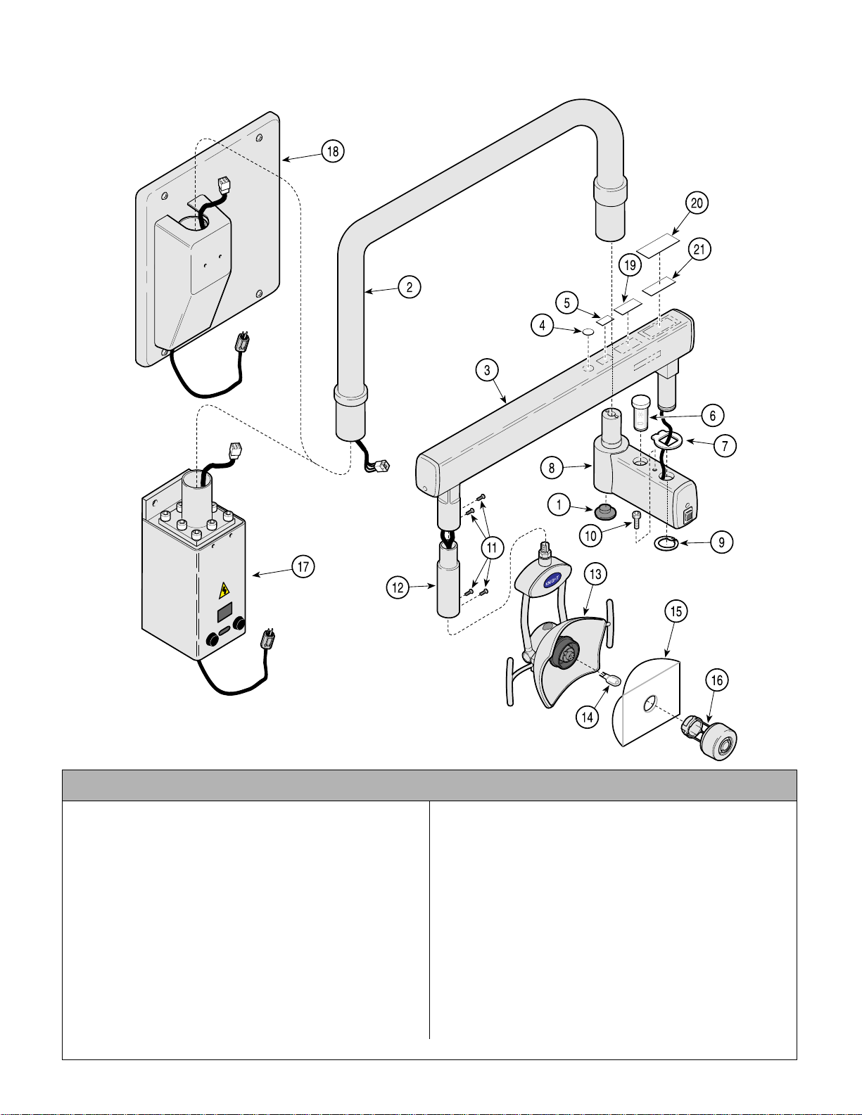
Wall/Cabinet Mounted Light Assembly
Return To Table Of Contents
(Long Arm) 152686-01
SECTION VI
PARTS LIST
NOTE: This model
uses Pebble Grey
painted components.
AF202901i
Used on Units with “ PH” Serial Number Prefix
Item Part No. Description Qty. Item Part No. Description Qty.
152686-01 120 VAC wall/ C ab in et M ounted Light
Assembly (Includes Items 1 thru 16) ..... 1
1 • 12176 8-50 • Hole Plug............................................ 1
2 • 15306 8-01 • Light Post Assembly ..........................1
3 • 15250 4-01 • Flex Arm Assy (Refer to “Light Flex
Arm Assy” Elsewhere)........................ 1
4 • 061-0652-00 • Type B Label....................................... 1
5 • 061-0665-00 • CE Label ............................................. 1
6 • 15250 7 • Model “L” Spare Bulb .........................1
7 • 12186 1-2 • Locking Wa sher ................................. 1
8 • 15268 4-01 • Fixed Arm Assy (Refer to “Light Fixed
Arm Assy” Elsewhere)........................ 1
9 • 11006 5 • Retaining Ring.................................... 1
10 • 152786 • Stop Rotation Screw Assembly .......... 1
Always Specify Model & Serial Number
© Midmark Corporation 2000 SF-1618 Printed in U.S.A.
Rev. 6/01
Page 6-13
11 • 121337-2 • Screw .................................................4
12 • 121843-50 • Light Post Extension ...........................1
13 • 152481-01 • Li ght Head (Refer to “Model ‘L’ Li ght
Head Assembly” Elsewhere)...............1
14 • 121720 • Dental Light Bulb ...................... ..........1
15 • 122845 • Model “L” Safety Shield ......................1
16 • 152479-01 • Lamp Shield Assembly .......................1
17 • 152683-01 • 120 VAC Cabinet Mount Assy (Refer to
“Cabinet Mount Assy” Elsewhere).......1
18 • 152544-01 • 120 VAC Wall Mount Assy (Refer to
“Wall Mount Assy” Elsewhere)............1
19 ••ETL Label........................................ Ref
20 ••Serial Number Label .......................Ref
21 • 061-0741-00 • Clear Laminate (To Cover S/N Label) .1
Page 64
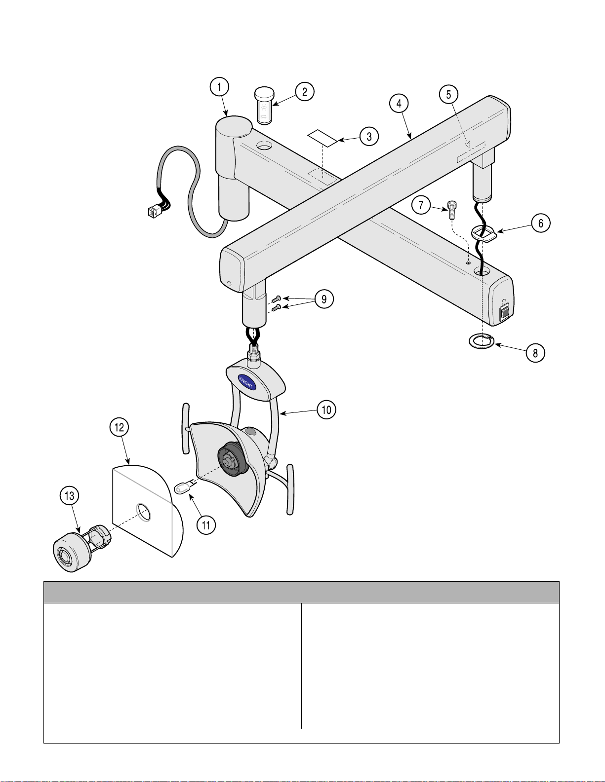
Remote Transformer Unit Light
Return To Table Of Contents
Assembly 152505
SECTION VI
PARTS LIST
Used on Units with “ LL” Serial Number Prefix
Item Part No. Description Qty. Item Part No. Description Qty.
152505 120 VAC Unit Mounted Li ght
Assembly (Includes Items 1 thru 13) ..... 1
1 • 15250 6 • Fixed Arm As sy ( Refer to “Ligh t Fixed
Arm Assy” Elsewhere)........................ 1
2 • 15250 7 • Model “L” Spare Bulb .........................1
3 • TPW1376 • 120 VAC Model “L” Rating Plate ........ 1
4 • 15250 4 • Flex Arm Assy (Refer to “Light Flex
Arm Assy” Elsewhere)........................ 1
5 • • Serial Nameplate.............................Ref
6 • 12167 7-2 • Light Arm Stop Washer ...................... 1
© Midmark Corporation 2000 SF-1618 Printed in U.S.A.
Rev. 6/01
NOTE: This model
uses Sterling Grey
painted components.
AF202800i
7 • 15278 6 • Stop Rotation Screw Assembly .......... 1
8 • 11006 5 • Retaining Ring.....................................1
9 • 12133 7-2 • Screw .................................................2
10 • 152481 • Light Head ( Refer to “Model ‘L’ Light
Head Assembly” Elsewhere)...............1
11 • 121720 • Dental Light Bulb ...................... ..........1
12 • 122845 • Model “L” Safety Shield ......................1
13 • 152479 • Lamp Shield Assembly .......................1
Always Specify Model & Serial Number
Page 6-14
Page 65
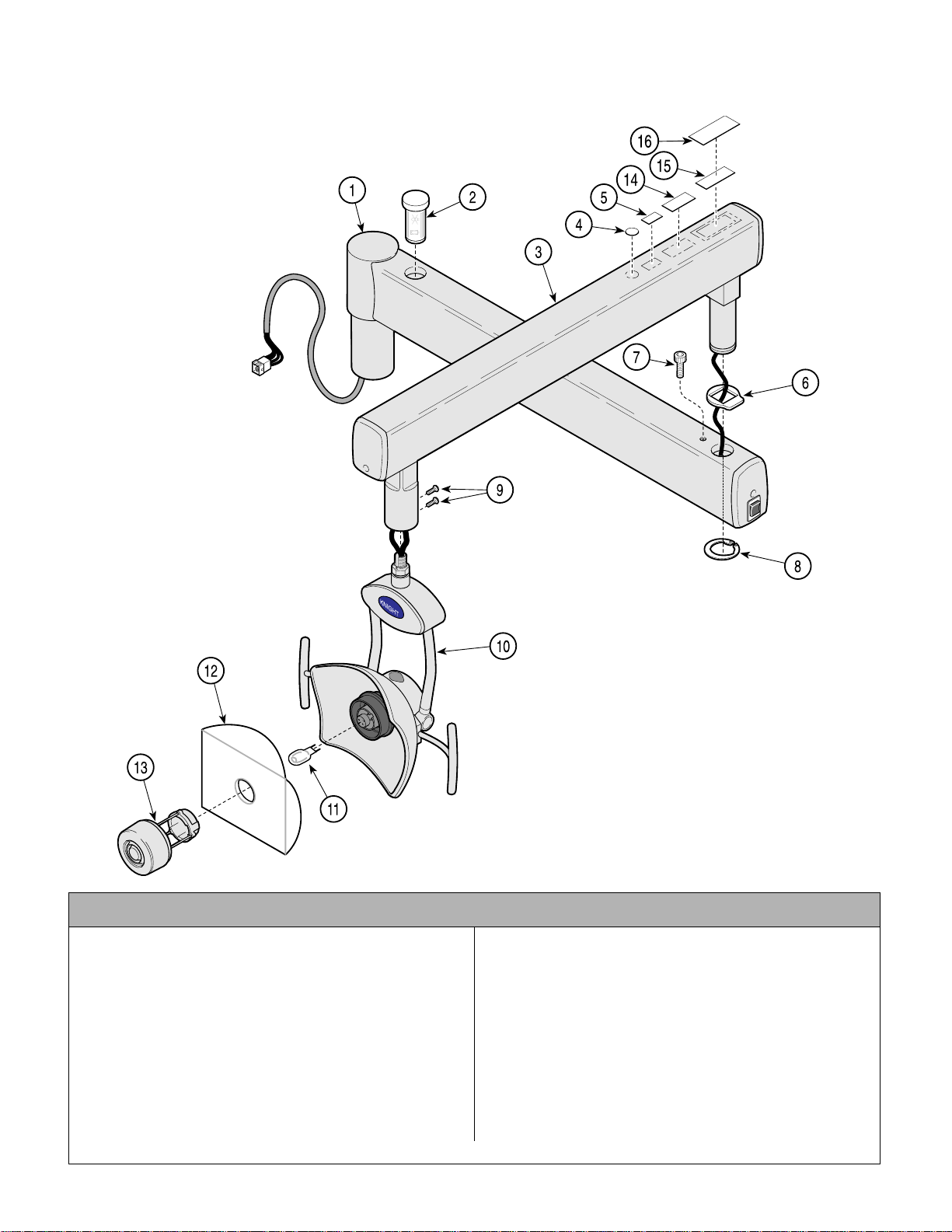
Remote Transformer Unit Light
Return To Table Of Contents
Assembly 152505-01
SECTION VI
PARTS LIST
Used on Units with “ PH” Serial Number Prefix
Item Part No. Description Qty. Item Part No. Description Qty.
152505-01 120 VAC Unit Mounted Light
Assembly (Includes Items 1 thru 13) ..... 1
1 • 15250 6 • Fixed Arm As sy ( Refer to “Ligh t Fixed
Arm Assy” Elsewhere)........................ 1
2 • 15250 7 • Model “L” Spare Bulb .........................1
3 • 15250 4-01 • Flex Arm Assy (Refer to “Light Flex
Arm Assy” Elsewhere)........................ 1
4 • 061-0652-00 • Type B Label....................................... 1
5 • 061-0665-00 • CE Label ............................................. 1
6 • 12167 7-2 • Light Arm Stop Washer ...................... 1
7 • 15278 6 • Stop Rotation Screw Assembly ......... 1
© Midmark Corporation 2000 SF-1618 Printed in U.S.A.
Rev. 6/01
NOTE: This model
uses Pebble Grey
painted components.
AF202801i
8 • 11006 5 • Retaining Ring.....................................1
9 • 12133 7-2 • Screw .................................................2
10 • 152481-01 • Li ght Head (Refer to “Model ‘L’ Li ght
Head Assembly” Elsewhere)...............1
11 • 121720 • Dental Light Bulb ...................... ..........1
12 • 122845 • Model “L” Safety Shield ......................1
13 • 152479-01 • Lamp Shield Assembly .......................1
14 ••ETL Label........................................ Ref
15 ••Serial Number Label .......................Ref
16 • 061-0741-00 • Clear Laminate (To Cover S/N Label) .1
Always Specify Model & Serial Number
Page 6-15
Page 66
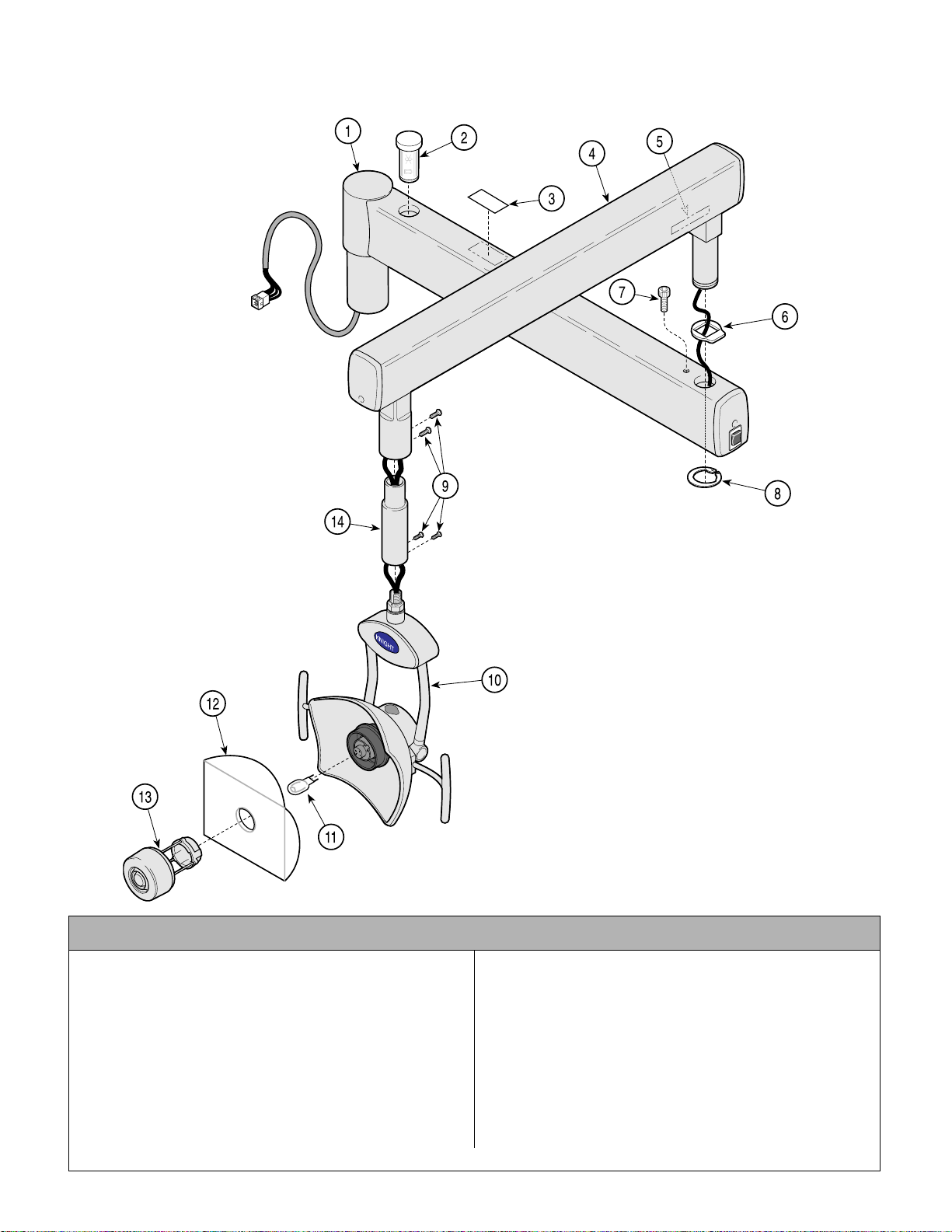
Wall/Cabinet Mounted Light Assembly
Return To Table Of Contents
(Short Arm) 152569
SECTION VI
PARTS LIST
Used on Units with “ LL” Serial Number Prefix
Item Part No. Description Qty. Item Part No. Description Qty.
152569 120 VAC Wall Mounted Light
Assembly (Includes Items 1 thru 14) ..... 1
1 • 15250 6 • Fixed Arm As sy ( Refer to “Ligh t Fixed
Arm Assy” Elsewhere)........................ 1
2 • 15250 7 • Model “L” Spare Bulb .........................1
3 • TP1376 • 120 VAC Model “L” Rating Plate ........ 1
4 • 15250 4 • Flex Arm Assy (Refer to “Light Flex
Arm Assy” Elsewhere)........................ 1
5 • • Serial Nameplate.............................Ref
6 • 12167 7-2 • Light Arm Stop Washer ...................... 1
© Midmark Corporation 2000 SF-1618 Printed in U.S.A.
Rev. 6/01
NOTE: This model
uses Sterling Grey
painted components.
AF203800i
7 • 15278 6 • Stop Rotation Screw Assembly........... 1
8 • 11006 5 • Retaining Ring.....................................1
9 • 12133 7-2 • Screw .................................................4
10 • 152481 • Light Head ( Refer to “Model ‘L’ Light
Head Assembly” Elsewhere)...............1
11 • 121720 • Dental Light Bulb ...................... ..........1
12 • 122845 • Model “L” Safety Shield ......................1
13 • 152479 • Lamp Shield Assembly .......................1
14 • 121834-1 • Light Post Extension ...........................1
Always Specify Model & Serial Number
Page 6-16
Page 67
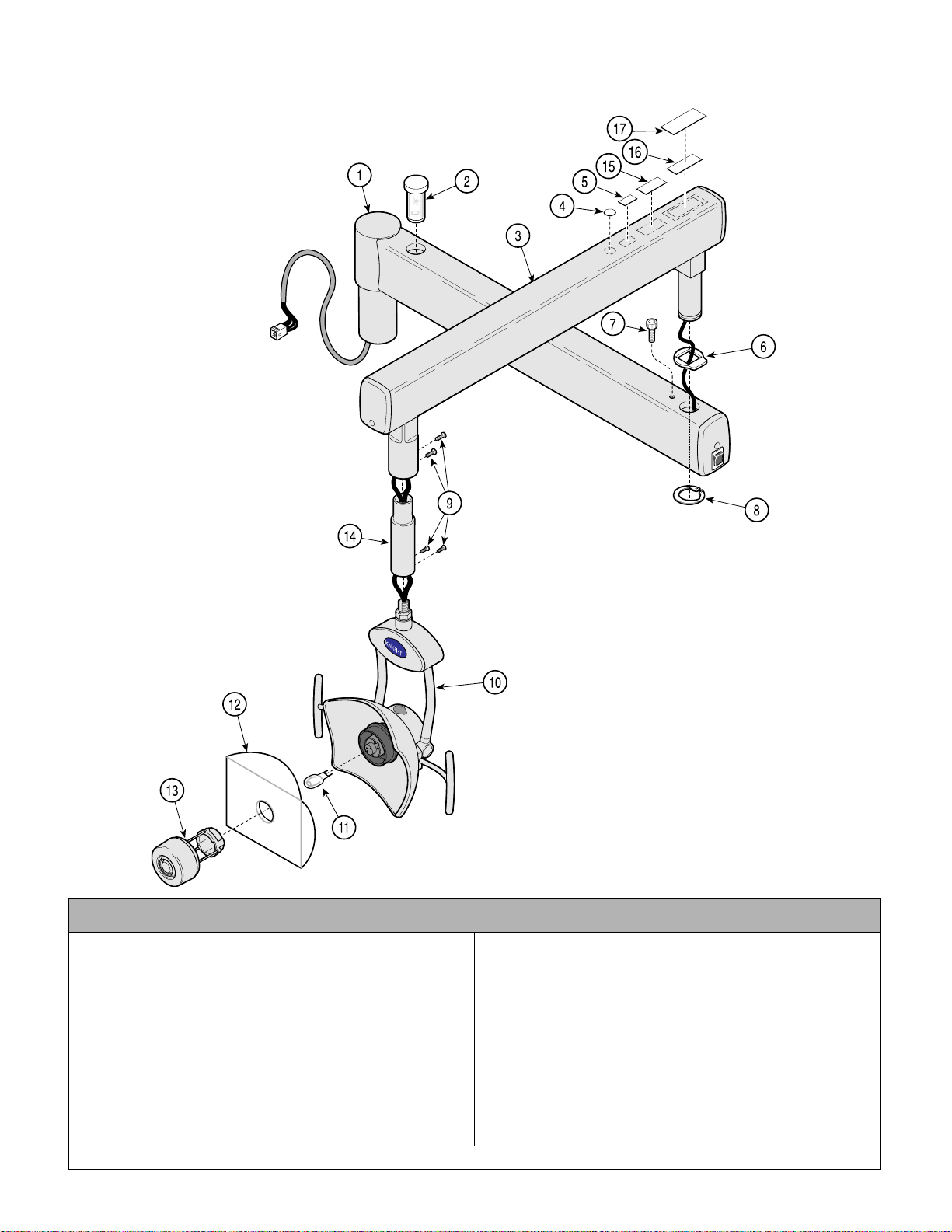
Wall/Cabinet Mounted Light Assembly
Return To Table Of Contents
(Short Arm) 152569-01
SECTION VI
PARTS LIST
Used on Units with “ PH” Serial Number Prefix
Item Part No. Description Qty. Item Part No. Description Qty.
152569-01 120 VAC Wall Mount ed Li ght
Assembly (Includes Items 1 thru 14) ..... 1
1 • 15250 6 • Fixed Arm As sy ( Refer to “Ligh t Fixed
Arm Assy” Elsewhere)........................ 1
2 • 15250 7 • Model “L” Spare Bulb .........................1
3 • 15250 4-01 • Flex Arm Assy (Refer to “Light Flex
Arm Assy” Elsewhere)........................ 1
4 • 061-0652-00 • Type B Label....................................... 1
5 • 061-0665-00 • CE Label ............................................. 1
6 • 12167 7-2 • Light Arm Stop Washer ...................... 1
7 • 15278 6 • Stop Rotation Screw Assembly .......... 1
© Midmark Corporation 2000 SF-1618 Printed in U.S.A.
Rev. 6/01
NOTE: This model
uses Pebble Grey
painted components.
AF2038001i
8 • 11006 5 • Retaining Ring.....................................1
9 • 12133 7-2 • Screw .................................................4
10 • 152481-01 • Li ght Head (Refer to “Model ‘L’ Li ght
Head Assembly” Elsewhere)...............1
11 • 121720 • Dental Light Bulb ...................... ..........1
12 • 122845 • Model “L” Safety Shield ......................1
13 • 152479-01 • Lamp Shield Assembly .......................1
14 • 121834-50 • Light Post Extension ...........................1
15 ••ETL Label........................................ Ref
16 ••Serial Number Label .......................Ref
17 • 061-0741-00 • Clear Laminate....................................1
Always Specify Model & Serial Number
Page 6-17
Page 68
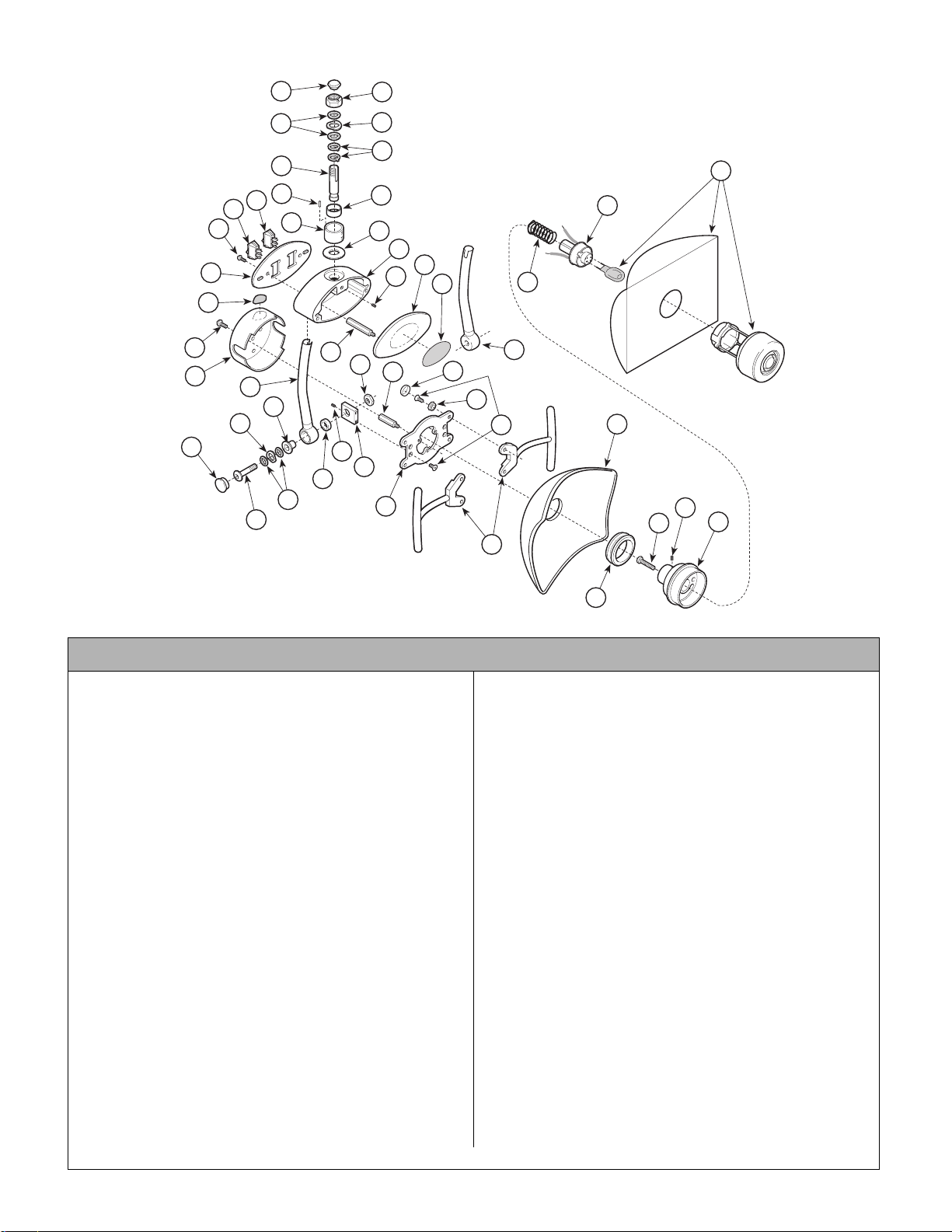
Light Head Assembly
Return To Table Of Contents
152481
43
42
SECTION VI
PARTS LIST
34
30
31
24
23
21
NOTE: This model
uses Sterling Grey
painted components.
32
18
12
33
19
20
40
38
37
17
36
16
27
46
15
14
35
41
39
44
11
22
29
28
26
KNIGHT
25
10
47
1
2
13
9
45
8
7
4
6
5
3
AF2018
Used on Units with “ LL” Serial Number Prefix
Item Part No. Description Qty. Item Part No. Description Qty.
152481 Model “L” Light Head Assembly
(Includes Items 1 thru 44)
1 • 152 485 • Lamp Holder Assembly....................... 1
2 • 114 040 • Compression Spring ...........................1
3 • 121 579-2 • Lens Support Housing ....................... 1
4 • 116 566 • Set Screw ........................................... 3
5 • 104 847 • Grommet ............................................ 1
6 • 109 104 • Socket Head Screw ............................ 1
7 • 152 615 • Reflector Kit ....................................... 1
8 • 122 822-1 • Light Handle Assembly ......................2
9 • 121 799 • Screw Base ........................................4
10 • 122798 • Screw Cover........................................ 4
153268 Bumper Kit (Includes Items 9, 10 & 45). 1
11 • 121681-1 • Light Head Pivot Frame ..................... 4
12 • 152484-1 • LH Light Head Strut Assembly ...........1
13 • 152483-1 • RH Light Head Strut Assembly ..........1
14 • 121682-2 • Light Head Pivot Block .......................2
15 • 121699 • Hex Jam Nut ............................. ......... 2
16 • 121701 • Light Head Pivot Spacer ....................2
17 • 121693-3 • Flat Washer ........................................ 4
18 • 117706 • Washer ...............................................2
19 • 121809-2 • Light Head Pivot Stud ........................2
20 • 121562-3 • Light Pivot Bushing ............................ 2
21 • 121673-1 • Light Head Pivot Cap ......................... 2
22 • 121675 • Standoff ..............................................3
23 • 121564 • Light Head Cover ...............................1
24 • 121697-1 • Screw..................................................3
Always Specify Model & Serial Number
25 • 121527 • Small Logo ..........................................1
26 • 121615-6 • Light Front Cover ................................1
27 • 121674 • Standoff ..............................................2
28 • 121683-1 • Light Head Switches Housing ............1
29 • 121700 • Screw ..................................................6
30 • 121614-1 • Light Switch Mounting Cover ..............1
31 • TPW1450 • Bilingual Warning Label ......................1
32 • 121664 • SPDT On/Off/Auto Switch ..................1
153248 Light Switch Kit (Replaces 2 Position
with 3 Position Switch on Older Units)...1
33 • 121665 • SPDT Composite Switch ....................1
34 • 121698-1 • Screw ..................................................2
35 • 121679 • Washer ...............................................1
36 • 121568-2 • Bearing Support Sleeve .....................1
37 • 121567 • Chamfered Straight Pin ......................1
38 • 121680-2 • Light Head Swivel Pin .........................1
39 • 115657-3 • Pivot Pin Stop .....................................2
40 • 113451 • Bearing Washer ..................................2
41 • C5593 • Washer ...............................................1
42 • 113429-2 • Hex Lock Nut ...................... ................1
43 • 117604 • Grommet ............................................1
44 • 121678 • Sleeve Bearing ...................................1
45 • 122815 • Screw ..................................................4
46 • 116566 • Set Screw ...........................................2
47 • Bulb and Shield Components (Refer to
Model “L” Universal Light Assembly”
Elsewhere).......................................Ref
© Midmark Corporation 2000 SF-1618 Printed in U.S.A.
Page 6-18
Page 69
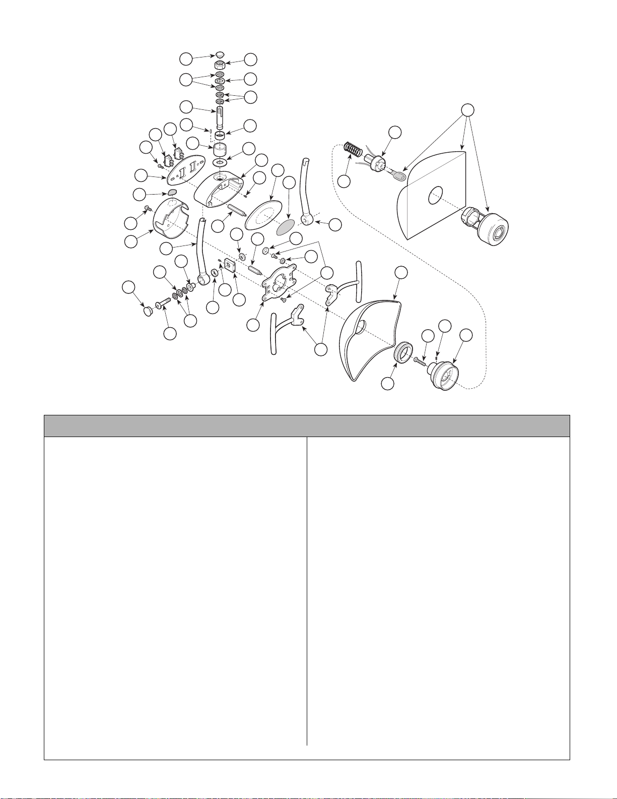
Light Head Assembly
Return To Table Of Contents
152481-01
43
42
SECTION VI
PARTS LIST
30
31
24
23
21
NOTE: This model
uses Pebble Grey
painted components.
34
32
18
12
33
19
20
40
38
37
17
36
16
27
46
15
14
44
35
41
39
11
22
29
28
26
KNIGHT
25
10
47
1
2
13
9
45
8
7
4
6
5
3
AF2018
Used on Units with “ PH” Serial Number Prefix
Item Part No. Description Qty. Item Part No. Description Qty.
152481-01 Model “L” Light Head Assembly
(Includes Items 1 thru 44)
1 • 152 485 • Lamp Holder Assembly....................... 1
2 • 114 040 • Compression Spring ...........................1
3 • 121 579-2 • Lens Support Housing ....................... 1
4 • 116 566 • Set Screw ........................................... 3
5 • 104 847 • Grommet ............................................ 1
6 • 109 104 • Socket Head Screw ............................ 1
7 • 152 615 • Reflector Kit ....................................... 1
8 • 122 822-50 • Light Handle Assembly ...................... 2
9 • 121 799 • Screw Base ........................................4
10 • 122798-01 • Screw Cover........................................4
153268 Bumper Kit (Includes Items 9, 10 & 45). 1
11 • 121681-50 • Light Head Pivot Frame .....................4
12 • 152484-50 • LH Light Head Strut Assembly ........... 1
13 • 152483-50 • RH Light Head Strut Assembly .......... 1
14 • 121682-2 • Light Head Pivot Block .......................2
15 • 121699 • Hex Jam Nut ............................. ......... 2
16 • 121701 • Light Head Pivot Spacer ....................2
17 • 121693-3 • Flat Washer ........................................ 4
18 • 117706 • Washer ...............................................2
19 • 121809-2 • Light Head Pivot Stud ........................2
20 • 121562-3 • Light Pivot Bushing ............................ 2
21 • 121673-50 • Light Head Pivot Cap .........................2
22 • 121675 • Standoff ..............................................3
23 • 121564 • Light Head Cover ...............................1
24 • 121697-50 • Screw..................................................3
Always Specify Model & Serial Number
25 • 061-0771-00• Small Logo1
26 • 121615-50 • Light Front Cover ................................1
27 • 121674 • Standoff ..............................................2
28 • 121683-50 • Light Head Switches Housing ............1
29 • 121700 • Screw ..................................................6
30 • 121614-50 • Light Switch Mounting Cover ..............1
31 • TPW1450 • Bilingual Warning Label ......................1
32 • 121664 • SPDT On/Off/Auto Switch ..................1
153248 Light Switch Kit (Replaces 2 Position
with 3 Position Switch on Older Units)...1
33 • 121665 • SPDT Composite Switch ....................1
34 • 121698-50 • Screw ..................................................2
35 • 121679 • Washer ...............................................1
36 • 121568-2 • Bearing Support Sleeve .....................1
37 • 121567 • Chamfered Straight Pin ......................1
38 • 121680-2 • Light Head Swivel Pin .........................1
39 • 115657-3 • Pivot Pin Stop .....................................2
40 • 113451 • Bearing Washer ..................................2
41 • C5593 • Washer ...............................................1
42 • 113429-2 • Hex Lock Nut ...................... ................1
43 • 117604 • Grommet ............................................1
44 • 121678 • Sleeve Bearing ...................................1
45 • 122815 • Screw ..................................................4
46 • 116566 • Set Screw ...........................................2
47 • Bulb and Shield Components (Refer to
Model “L” Universal Light Assembly”
Elsewhere).......................................Ref
© Midmark Corporation 2000 SF-1618 Printed in U.S.A.
Page 6-19
Page 70
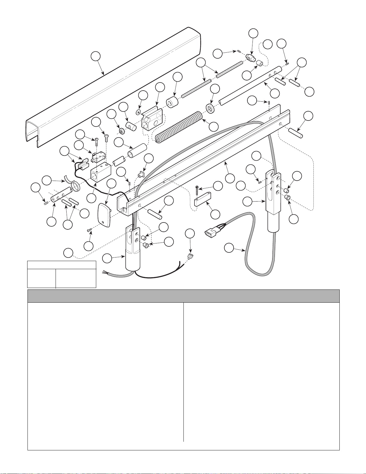
Light Flex Arm Assembly
Return To Table Of Contents
152504
NOTE: This model
uses Sterling Grey
painted components.
1
32
SECTION VI
PARTS LIST
10
11
A
11
3
12
13
18
17
33
20
11
4
13
C
TORQUE LEGEND
ITEM# TORQUE
19 32 - 42 IN-LBS
(3.6 - 4.7 N• M)
C
29
16
19
30
15
28
7
26
14
5
6
9
4
B
26
23
8
27
A
26
25
24
23
21
22
2
B
31
25
35
24
34
AF2019
Used on Units with “ LL” Serial Number Prefix
Item Part No. Description Qty. Item Part No. Description Qty.
152504 Light Flex Arm Assembly
(Includes Items 1 thru 35)
1 • 12172 3-1 • Light Flex Arm Cover.......................... 1
2 • 12172 2-1 • Light Flex Arm Channel......................1
3 • 12174 2 • Threaded Rod .................................... 1
4 • 12171 2 • Light Flex Arm Shaft ..........................1
5 • 12173 7-2 • Spring Retainer Block ........................1
6 • 12174 1 • Spring Guide Pad ...............................2
7 • 12173 8 • Spring Retainer Block Bushing .......... 1
8 • 12172 9 • Compression Spring ..........................1
9 • 12172 5-2 • Spring Support Washer .....................1
10 • 122995 • Spring Rod Pin ................... ................ 1
11 • 110790 • Screw ................................................. 3
12 • 122997 • Sleeve Bearing ................................... 2
13 • 121727 • Dowel Pin (Apply Loctite #K906111) .4
14 • 121735-2 • Spring Retainer Pin ............................1
15 • C1269 • Hex Nut ....................... ....................... 1
16 • 121739-2 • Switch Mounting Block .......................1
17 • 146978 • Micro Switch ......................................1
18 • 122806 • Screw ................................................. 2
Always Specify Model & Serial Number
© Midmark Corporation 2000 SF-1618 Printed in U.S.A.
Page 6-20
19 • 040-0010-126 • Screw ..................................................4
20 • 115896 • Cable Tie.............................................2
21 • 121740-2 • Switch Acuator Block ..........................1
22 • 118653 • Screw .................................................2
23 • 121728 • Dowel Pin (Apply Loctite #K906111) ..2
24 • 121716 • Flange Bearing ...................................4
25 • 121714 • Sleeve Bearing ...................................4
26 • 121747 • Set Screw ...........................................6
27 • 121724 • Threaded Insert ..................................2
28 • 121726-1 • Flex Arm End Cap ..............................2
29 • 121697-1 • Screw .................................................2
30 • 121565-1 • Flex Arm Light Head Po st ...................1
31 • 121713-1 • Flex Arm End Post ...................... ........1
32 • 122487 • Rod Dampener ............... ....................1
33 • 152502 • Auto ON/OFF Wire Assembly (Refer
to “Wiring Diagram” Elsewhere) .......... 1
34 • 152501 • Light Arm Cable Assembly (Refer to
“Wiring Diagram” Elsewhere) .............1
35 • 122753 • Terminal ..............................................4
Page 71
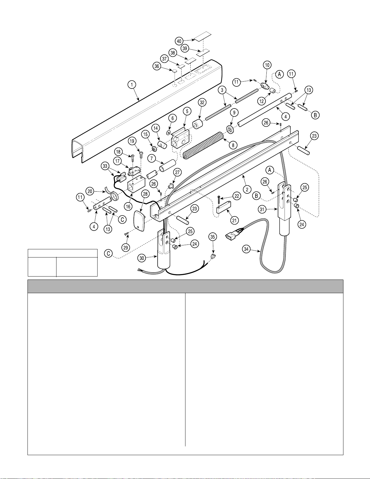
Light Flex Arm Assembly
Return To Table Of Contents
152504-01
NOTE: This model
uses Pebble Grey
painted components.
SECTION VI
PARTS LIST
TORQUE LEGEND
ITEM# TORQUE
19 32 - 42 IN-LBS
(3.6 - 4.7 N•M)
AF201901i
Used on Units with Serial Number PH1000 thru PH1676
Item Part No. Description Qty. Item Part No. Description Qty.
152504-01 Light Flex Arm Assembly
(Includes Items 1 thru 35)
1 • 121723-50 • Light Flex Arm Cover.......................... 1
2 • 121722-50 • Light Flex Arm Channel ...................... 1
3 • 121742 • T h readed Rod .................................... 1
4 • 121712 • L ig ht Flex Arm Shaft .......................... 1
5 • 121737-2 • Spring Retainer Block ........................1
6 • 121741 • S p r ing Guide Pad ...............................2
7 • 121738 • Spring Retainer Block Bushing .......... 1
8 • 121729 • C o mpression Spring .......................... 1
9 • 121725-2 • Spring Support Washer .....................1
10 • 122995 • Spring Rod Pin ................................... 1
11 • 110790 • Screw ................................................. 3
12 • 122997 • SleeveB e ar ing ...................................2
13 • 121727 • DowelPin (Apply Loctite #K906111) . 4
14 • 121735-2 • Spring Retainer Pin ............................1
15 • C1269 • Hex Nut ..............................................1
16 • 121739-2 • Switch Mounting Block .......................1
17 • 146978 • Micro Switch ......................................1
18 • 122806 • Screw ................................................. 2
19 • 040-0010-126 • Screw..................................................4
20 • 115896 • Cable Tie............................................. 2
Always Specify Model & Serial Number
21 • 121740-2 • Switch Acuator Block ..........................1
22 • 118653 • Screw .................................................2
23 • 121728 • Dowel Pin (Apply Loctite #K906111) .. 2
24 • 121716 • Flange B earing ...................................4
25 • 121714 • Sleeve Bearing ...................................4
26 • 121747 • Set Screw ...........................................6
27 • 121724 • Threaded Insert ..................................2
28 • 121726-50 • Flex Arm End C ap ..............................2
29 • 121697-50 • Screw .................................................2
30 • 121565-50 • Flex Arm Light Head Post ...................1
31 • 121713-1 • Flex Arm E nd Post ..............................1
32 • 122487 • Rod Dampener ...................................1
33 • 152502 • Auto ON/OFF Wire Assembly (Refer
to “Wiring Diagram” Elsewhere) ..........1
34 • 152501 • LightArm Cable Assembly (Refer to
“Wiring Diagram” Elsewhere).............1
35 • 122753 • Terminal ..............................................4
36 • 061-0652-00 • Type B Label........................................1
37 • 061-0665-00 • CE Label ..............................................1
38 • • ETL Label........................................Ref
39 • • Serial NumberLabel........................ Ref
40 • 061-0741-00 • Clear Laminate (To Cover S/N Label)..1
© Midmark Corporation 2000 SF-1618 Printed in U.S.A.
Rev. 9/01
Page 6-21
Page 72
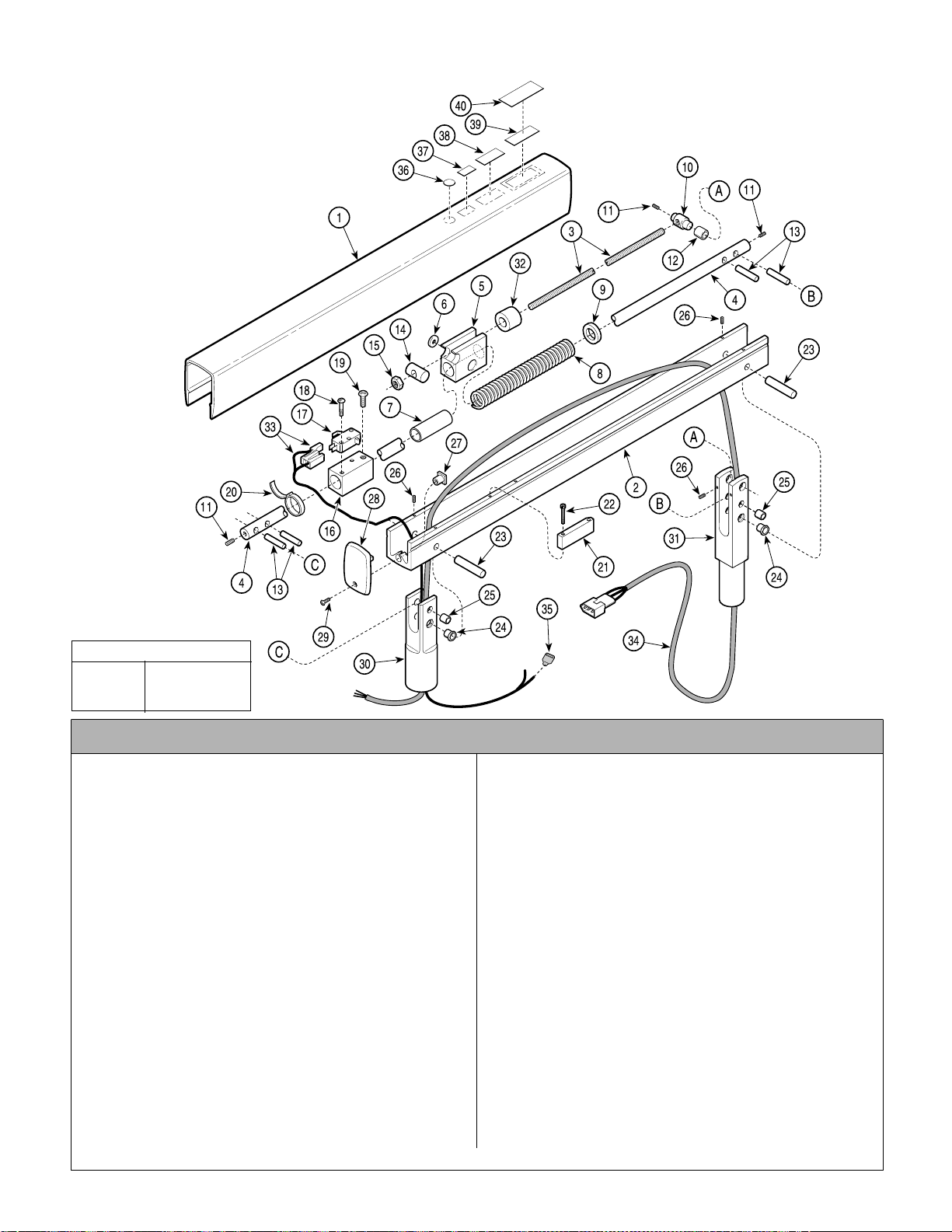
Light Flex Arm Assembly
Return To Table Of Contents
152504-01
NOTE: This model
uses Pebble Grey
painted components.
SECTION VI
PARTS LIST
TORQUE LEGEND
ITEM# TORQUE
19 32 - 42 IN-LBS
(3.6 - 4.7 N•M)
AF201901i
Used on Units with Serial Number PH1677 thru Present
Item Part No. Description Qty. Item Part No. Description Qty.
152504-01 Light Flex Arm Assembly
(Includes Items 1 thru 35)
1 • 121723-50 • Light Flex Arm Cover.......................... 1
2 • 121722-50 • Light Flex Arm Channel ...................... 1
3 • 121742 • T h readed Rod .................................... 1
4 • 121712 • L ig ht Flex Arm Shaft .......................... 1
5 • 121737-2 • Spring Retainer Block ........................1
6 • 051-0981-00 • Spring Guide Pad ...............................2
7 • 121717 • Spring Retainer Block Bushing .......... 1
8 • 121729 • C o mpression Spring .......................... 1
9 • 121725-2 • Spring Support Washer .....................1
10 • 122995 • Spring Rod Pin ................................... 1
11 • 110790 • Screw ................................................. 3
12 • 122997 • SleeveB e ar ing ...................................2
13 • 121727 • DowelPin (Apply Loctite #K906111) . 4
14 • 121735-2 • Spring Retainer Pin ............................1
15 • C1269 • Hex Nut ..............................................1
16 • 121739-2 • Switch Mounting Block .......................1
17 • 146978 • Micro Switch ......................................1
18 • 122806 • Screw ................................................. 2
19 • 040-0010-126 • Screw..................................................4
20 • 115896 • Cable Tie............................................. 2
Always Specify Model & Serial Number
21 • 121740-2 • Switch Acuator Block ..........................1
22 • 118653 • Screw .................................................2
23 • 121728 • Dowel Pin (Apply Loctite #K906111) .. 2
24 • 121716 • Flange B earing ...................................4
25 • 121714 • Sleeve Bearing ...................................4
26 • 121747 • Set Screw ...........................................6
27 • 121724 • Threaded Insert ..................................2
28 • 121726-50 • Flex Arm End C ap ..............................2
29 • 121697-50 • Screw .................................................2
30 • 121565-50 • Flex Arm Light Head Post ...................1
31 • 121713-1 • Flex Arm E nd Post ..............................1
32 • 122487 • Rod Dampener ...................................1
33 • 152502 • Auto ON/OFF Wire Assembly (Refer
to “Wiring Diagram” Elsewhere) ..........1
34 • 152501 • LightArm Cable Assembly (Refer to
“Wiring Diagram” Elsewhere).............1
35 • 122753 • Terminal ..............................................4
36 • 061-0652-00 • Type B Label........................................1
37 • 061-0665-00 • CE Label ..............................................1
38 • • ETL Label........................................Ref
39 • • Serial NumberLabel........................ Ref
40 • 061-0741-00 • Clear Laminate (To Cover S/N Label)..1
© Midmark Corporation 2000 SF-1618 Printed in U.S.A.
Page 6-21.1
Page 73

SECTION VI
Return To Table Of Contents
PARTS LIST
This page intentionally left blank
© Midmark Corporation 2000 SF-1618 Printed in U.S.A.
Always Specify Model & Serial Number
Page 74
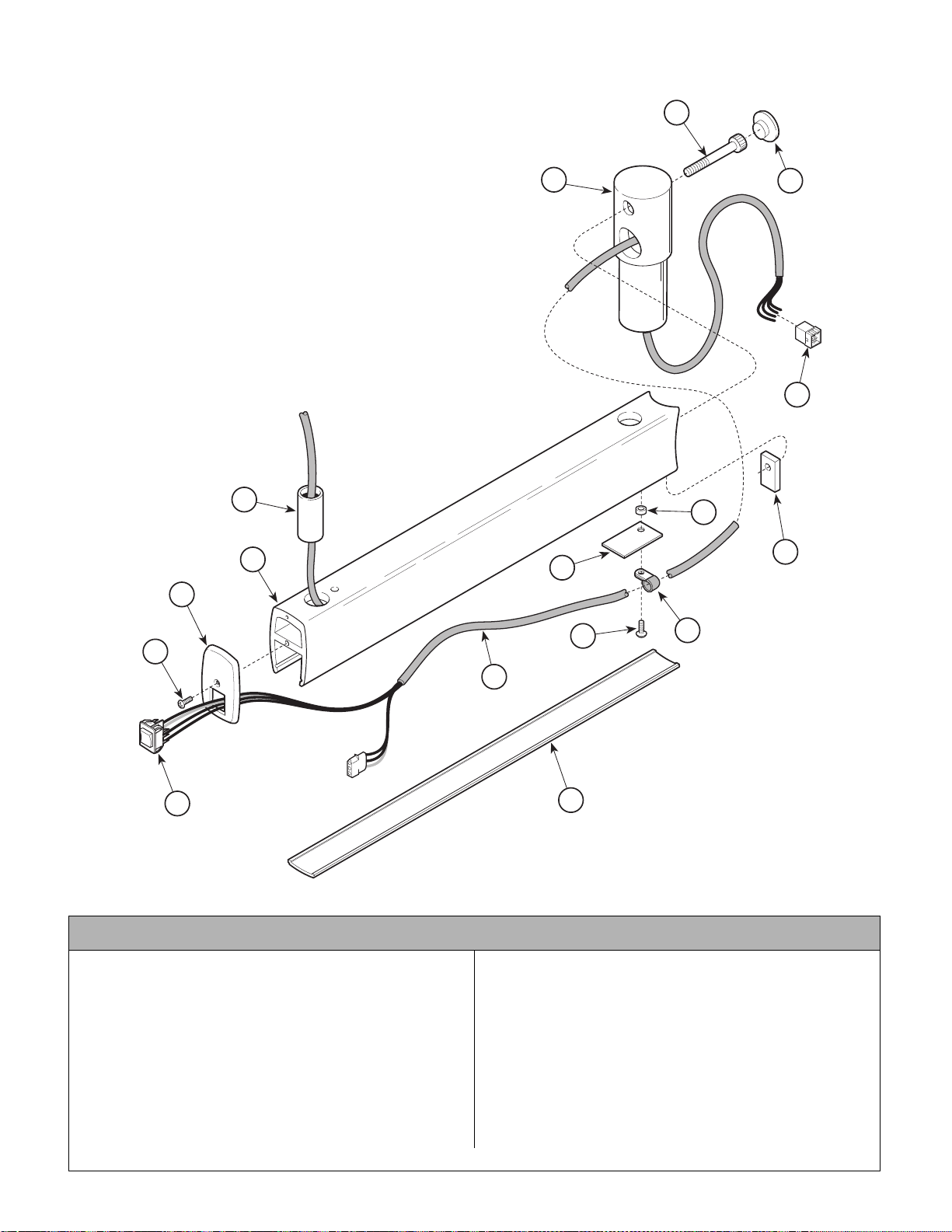
Unit/Wall Light Fixed Arm Assembly
Return To Table Of Contents
152506
SECTION VI
PARTS LIST
15
14
16
13
5
11
4
10
12
3
8
9
2
7
1
Used on Units with “LL” Serial Number Prefix
Item Part No. Description Qty. Item Part No. Description Qty.
152506 Light Fixed Arm Assembly (Includes
Items 1 thru 16)..................................... 1
1 • 121758 • 3 Position Progressive Rocker Switch 1
• 152508 • Blue Jumper (Not Shown)................... 1
2 • 121508-1 • Oval Head Screw ............. .................. 1
3 • 121764-1 • Rigid Arm Switch Cap ........................ 1
4 • 121705-1 • Unit Mounted Fixed Arm..................... 1
5 • 117505 • Bearing ............................................... 1
6 • 121707-1 • Fixed Arm Cover ................................1
7 • 152500 • Remote Trans former Cable Assembly 1
© Midmark Corporation 2000 SF-1618 Printed in U.S.A.
Rev. 5/03
6
NOTE: This model
uses Sterling Grey
painted components.
AF2021
8 • 121142 • Pan Head Screw ................................. 1
9 • 121656 • Cable Clamp .......................... .............1
10 • 121786-2 • Spare Bulb Hole Plate ........................1
11 • 121719 • Spacer.................................................1
12 • 117407-2 • Nut Post Plate ....................................1
13 • 102029 • 9 Pin Connector .................................1
14 • 121708-1 • Unit Mounted Hub .............................. 1
15 • 117519 • Socket Head Screw ............................1
16 • 122198-1 • Cap (Seal with RTV #185057) ............1
Always Specify Model & Serial Number
Page 6-22
Page 75
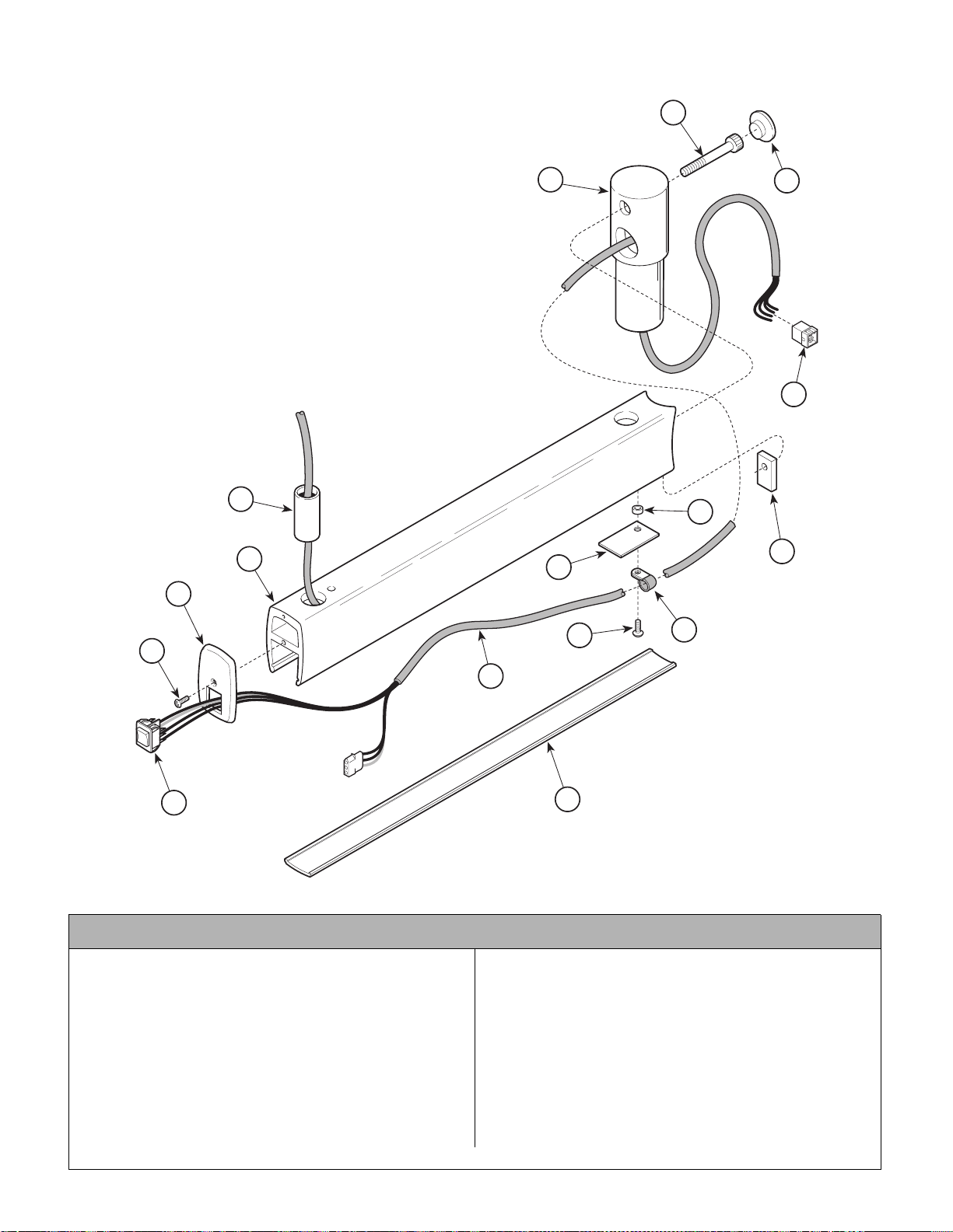
Unit/Wall Light Fixed Arm Assembly
Return To Table Of Contents
152506-01
SECTION VI
PARTS LIST
15
14
16
13
5
11
4
10
12
3
8
9
2
7
1
Used on Units with “PH” Serial Number Prefix
Item Part No. Description Qty. Item Part No. Description Qty.
152506-01 Light Fixed Arm Assembly (Includes
Items 1 thru 16)..................................... 1
1 • 12175 8 • 3 Position Progressive Rocker Switch 1
• 152508 • Blue Jumper (Not Shown)................... 1
2 • 12150 8-50 • Oval Head Screw ............. .................. 1
3 • 12176 4-50 • Rigid Arm Switch Cap ........................ 1
4 • 12170 5-1 • Unit Mounted Fixed Arm..................... 1
5 • 117505 • Bearing............................................... 1
6 • 12170 7-1 • Fixed Arm Cover ................................ 1
7 • 15250 0 • Remote Transformer Cable Assembly 1
© Midmark Corporation 2000 SF-1618 Printed in U.S.A.
Rev. 5/03
6
8 • 12114 2 • Pan Head Screw .................................1
9 • 12165 6 • Cable Clamp .................... ...................1
10 • 121786-2 • Spare Bulb Hole Plate ........................1
11 • 121719 • Spacer.................................................1
12 • 117407-2 • Nut Post Plate ....................................1
13 • 102029 • 9 Pin Connector .................................1
14 • 121708-1 • Unit Mounted Hub ..............................1
15 • 117519 • Socket Head Screw ............ ................1
16 • 122198-1 • Cap (Seal with RTV #185057) ............ 1
Always Specify Model & Serial Number
Page 6-23
NOTE: This model
uses Pebble Grey
painted components.
AF2021
Page 76
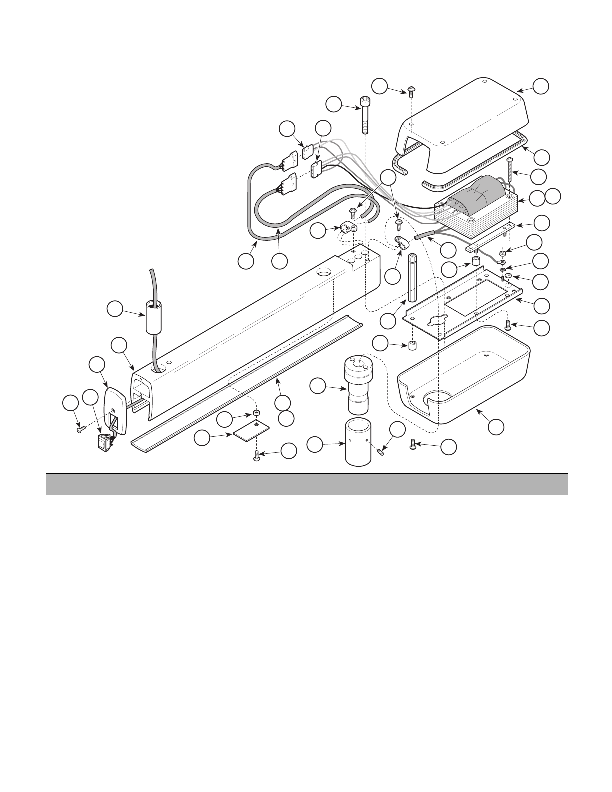
Universal Light Fixed Arm Assembly
Return To Table Of Contents
152482
SECTION VI
PARTS LIST
NOTE: This model
uses Sterling Grey
painted components.
5
4
3
34
33
36
6
37
32
35
7
31
29
30
28
23
26
3838
25
27
22
21
20
24
19
16
15
2
1
10
11
8
9
18
AF2020
12
14
13
17
Used on Units with “LL” Serial Number Prefix
Item Part No. Description Qty. Item Part No. Description Qty.
152482 120 VAC Universal Fixed Arm Assembly
(Includes Items 1 thru 37)...................... 1
1 • 121508-1 • Screw .................................................. 1
2 • 121758 • 3 Position Progressive Rocker Switch 1
• 152508 • Blue Jumper (Not Shown)................... 1
3 • 121764-1 • Rigid Arm Switch Cap ........................ 1
4 • 121745-1 • Fixed Universal Arm ........................... 1
5 • 117505 • Bearing ............................................... 1
6 • 102793 • 3 Circuit Connector ............................. 1
7 • 121655 • Cable Clamp ....................................... 1
8 • 121746-1 • Fixed Arm Cover ................................. 1
9 • 122078-2 • Cover Stop Pin (Not Shown)............... 1
10 • 119428 • Spacer ................................................ 1
11 • 121786-2 • Spare Bulb Hole Plate ........................ 1
12 • 121142 • Screw .................................................. 2
13 • 106753 • Set Screw ........................................... 1
14 • 122197-2 • Male Sleeve Light Bearing .................. 1
15 • 122196-2 • Male Light Pivot Bearing..................... 1
16 • 121719 • Lower Cover Spacer ........................... 4
17 • 121730-1 • Screw.................................................. 4
18 • 121744 • Bottom Light Transformer Cover......... 1
Always Specify Model & Serial Number
19 • 105816 • Screw ..................................................4
20 • 121466-2 • Light Transformer Chassis ..................1
21 • 112504 • Ground Identification Label ................. 1
22 • P14718 • External Tooth Washer ........................1
23 • P507 • Hex Nut ...............................................1
24 • 121676 • Top Cover Standoff..............................4
25 • 121656 • Cable Clamp........................................1
26 • 149418 • Power Cord Assembly.........................1
27 • 116420 • Vibration Isolator ................................. 4
28 • 152490 • Transformer Mounting Strip Assembly 2
29 • 152494 • 120 VAC Light Transformer Assembly 1
30 • 115896 • Cable Tie (Not Shown) .....................AR
31 • P2446 • Screw ..................................................4
32 • 053-1222-00 • Trim Ring .............................................1
33 • 121743 • Removable Light Transformer Cover ..1
34 • 120233 • Panel Screw ........................................4
35 • 101755 • Screw ..................................................2
36 • 121751 • Screw (Apply 042-0024-00, Loctite) ....2
37 • 112897 • 4 Circuit Connector..............................1
38 • 152499 • Intensity Switch Cable Assembly ........1
39 • 152501 • Light Arm Cable Assembly .................1
© Midmark Corporation 2000 SF-1618 Printed in U.S.A.
Rev. 8/03
Page 6-24
Page 77
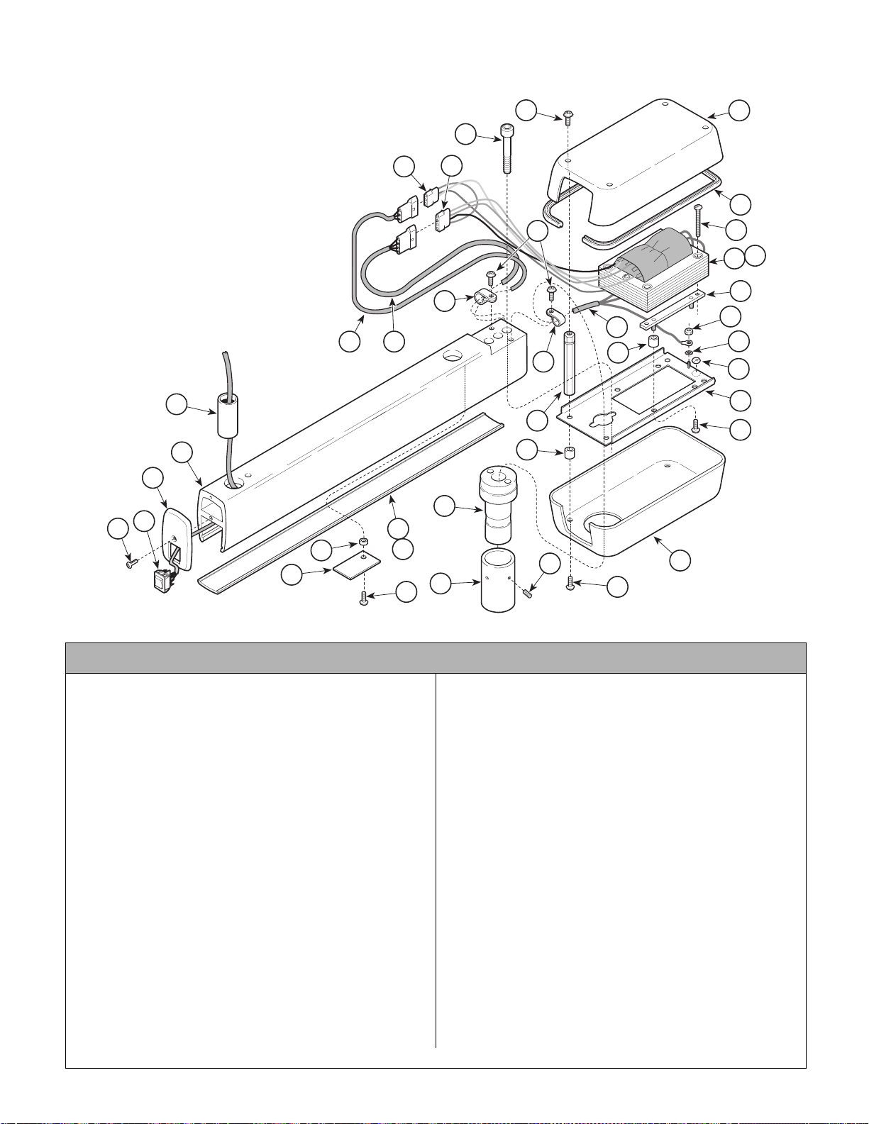
Universal Light Fixed Arm Assembly
Return To Table Of Contents
152482-01 (120 VAC) & 152591-01 (220 VAC)
SECTION VI
PARTS LIST
NOTE: This model
uses Pebble Grey
painted components.
5
4
3
2
1
11
10
34
33
36
6
37
32
29
23
31
30
28
22
21
35
7
26
3838
25
27
20
24
19
16
15
8
9
18
12
14
13
17
AF2020
Used on Units with “PH” Serial Number Prefix
Item Part No. Description Qty. Item Part No. Description Qty.
152482-01 120 VAC Universal Fixed Arm Assembly
(Includes Items 1 thru 39)...................... 1
152591-01 220 VAC Universal Fixed Arm Assembly
(Includes Items 1 thru 39)...................... 1
1 • 121508-50 • Screw .................................................. 1
2 • 121758 • 3 Position Progressive Rocker Switch 1
• 152508 • Blue Jumper (Not Shown)................... 1
3 • 121764-50 • Rigid Arm Switch Cap ........................ 1
4 • 121745-50 • Fixed Universal Arm ........................... 1
5 • 117505 • Bearing ............................................... 1
6 • 102793 • 3 Circuit Connector............................. 1
7 • 121655 • Cable Clamp ....................................... 1
8 • 121746-50 • Fixed Arm Cover................................. 1
9 • 122078-2 • Cover Stop Pin (Not Shown)............... 1
10 • 119428 • Spacer ................................................ 1
11 • 121786-2 • Spare Bulb Hole Plate ........................ 1
12 • 121142 • Screw.................................................. 2
13 • 106753 • Set Screw ........................................... 1
14 • 122197-2 • Male Sleeve Light Bearing.................. 1
15 • 122196-2 • Male Light Pivot Bearing..................... 1
16 • 121719 • Lower Cover Spacer ........................... 4
17 • 121730-50 • Screw.................................................. 4
18 • 121744 • Bottom Light Transformer Cover......... 1
Always Specify Model & Serial Number
19 • 105816 • Screw ..................................................4
20 • 121466-2 • Light Transformer Chassis .................. 1
21 • 112504 • Ground Identification Label ................. 1
22 • P14718 • External Tooth Washer ........................1
23 • P507 • Hex Nut ............................................... 1
24 • 121676 • Top Cover Standoff.............................. 4
25 • 121656 • Cable Clamp........................................1
26 • 149418-01 • Power Cord Assembly (120 VAC) .......1
• 149433 • Power Cord Assembly (220 VAC) .......1
27 • 116420 • Vibration Isolator .................................4
28 • 152490 • Transformer Mounting Strip Assembly 2
29 • 152494 • Light Transformer Assy. (120 VAC) .....1
• 152550 • Light Transformer Assy. (220 VAC) .....1
30 • 115896 • Cable Tie (Not Shown) .....................AR
31 • P2446 • Screw ..................................................4
32 • 053-1222-00 • Trim Ring.............................................1
33 • 121743 • Removable Light Transformer Cover ..1
34 • 120233 • Panel Screw ........................................ 4
35 • 117558 • Screw ..................................................2
36 • 121751 • Screw (Apply 042-0024-00, Loctite) .... 2
37 • 112897 • 4 Circuit Connector.............................. 1
38 • 152499 • Intensity Switch Cable Assembly ........1
39 • 152501 • Light Arm Cable Assembly .................1
© Midmark Corporation 2000 SF-1618 Printed in U.S.A.
Rev. 8/03
Page 6-25
Page 78
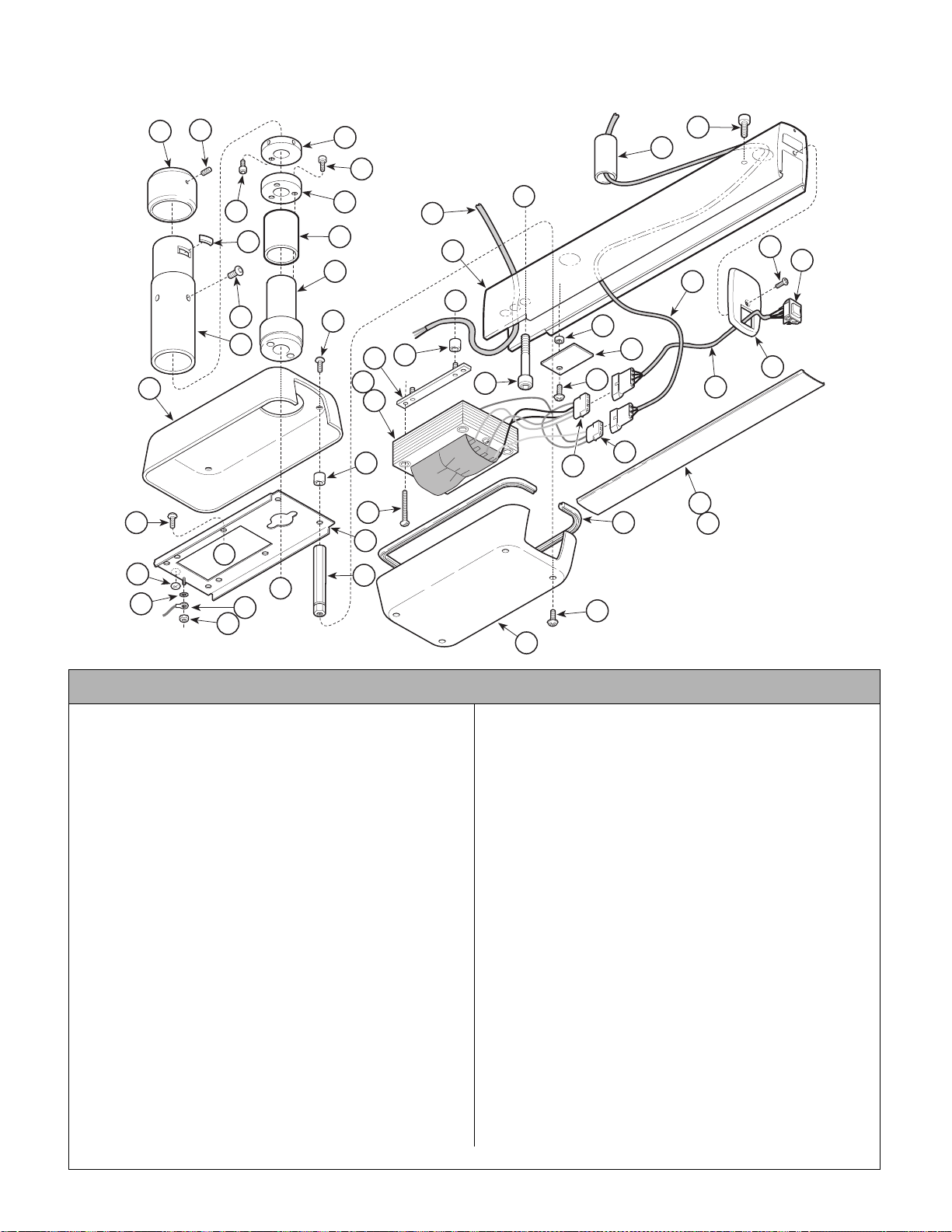
Ceiling Light Fixed Arm Assembly
Return To Table Of Contents
152566
SECTION VI
PARTS LIST
16
42
17
12
1
2
7
3
10
11
6
8
9
18
33
A
23
22
24
25
27
B
5
4
13
43
14
15
37
35
36
34
32
21
31
29
45
44
30
26
28
40
41
B
19
18
A
20
39
38
NOTE: This model
uses Sterling Grey
painted components.
AF2023
Used on Units with “LL” Serial Number Prefix
Item Part No. Description Qty. Item Part No. Description Qty.
152566 120 VAC Ceiling Fixed Ar m Assembly
(Includes Items 1 thru 45)..................... 1
1 • 11982 7 • Screw..................................................1
2 • 12179 0-1 • Retaining Collar.................................. 1
3 • 12178 9-2 • Post Mount Pin ................................... 1
4 • 12176 9-1 • Mounting Post..................................... 1
5 • 12184 1 • Screw..................................................4
6 • 12178 0-2 • Keeper ring......................................... 1
7 • 11755 8 • Screw..................................................1
8 • 11719 4 • Screw..................................................3
9 • 12178 1-2 • Stop Ring............................................ 1
10 • 121782 • Bearing ............................................... 1
11 • 121770-1 • Pivot Bearing ....................... ............... 1
12 • 121744 • Bottom Light Transformer Cover......... 1
13 • 121730-1 • Carriage bolt....................................... 4
14 • 121719 • Lower Cover Spacer........................... 4
15 • 121466-2 • Light Transformer Chassis..................1
16 • 105816 • Screw..................................................4
17 • P14718 • External Tooth Washer ....................... 1
18 • 149418 • 120 VAC Power Cable ........................1
19 • P507 • Hex Nut................................... ............ 1
20 • 121676 • Top Cover Standoff............................. 4
21 • 112897 • 4 Circuit Connector............................. 1
40 • 121746-1 • Fixed Arm Cover................................. 1
22 • 117505 • Bearing ............................................... 1
Always Specify Model & Serial Number
23 • 117636 • Stop Rotation Screw ........................ ...1
24 • 121508-1 • Screw ..................................................1
25 • 121758 • 3 Position Progressive Rocker Switch.1
• 152508 • Blue Jumper (Not Shown)...................1
26 • 121764-1 • Ridgid Arm Switch Cap .......................1
27 • 152501 • Light Arm Cable Assembly..................1
28 • 152499 • Intensity Switch Cable As sembly ........1
29 • 121719 • Spacer ................................................1
30 • 121786-2 • Spare Bulb Hole Plate.........................1
31 • 121142 • Screw..................................................1
32 • 121844 • Screw..................................................2
33 • 121745-1 • Fixed Arm............................................1
34 • 116420 • Vibration Isolator.................................4
35 • 152490 • Transformer Mount ing St r i p As sembly 2
36 • 152494 • 120 VAC Light Transformer Assembly.1
37 • P2446 • Screw ..................................................4
38 • 121743 • Removable Light Transformer Cover...1
39 • 120233 • Panel Screw ........................................4
40 • 121746-1 • Fixed Arm Cover .................................1
41 • 122078 • Cover Stop Pin (Not shown)................1
42 • 112504 • Ground Identification Labe l .................1
43 • 115896 • Cable Tie (Not Shown)........................1
44 • 053-1222-00 • Trim Ring............................................. 1
45 • 102793 • 3 Circuit Connector.............................1
© Midmark Corporation 2000 SF-1618 Printed in U.S.A.
Rev. 5/03
Page 6-26
Page 79
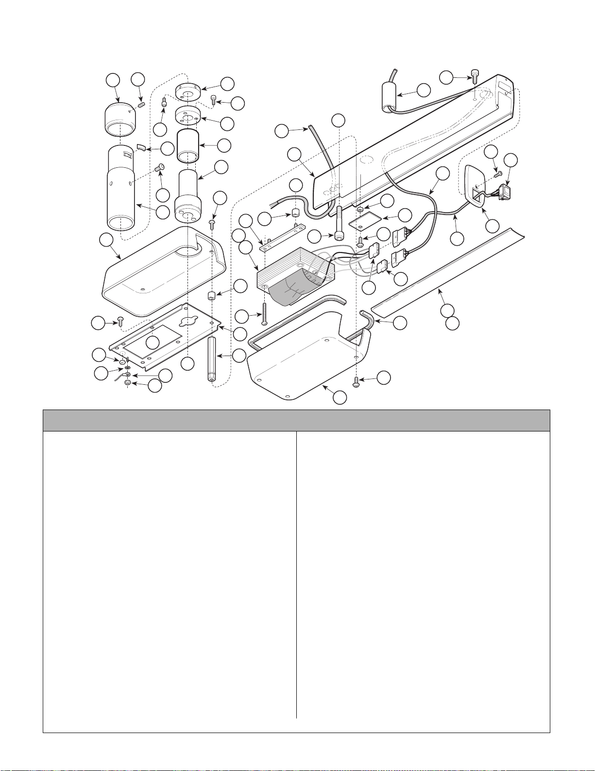
Ceiling Light Fixed Arm Assembly
Return To Table Of Contents
SECTION VI
PARTS LIST
152566-01 (120 VAC) & 152592-01 (220 VAC)
16
42
17
12
1
2
7
3
10
11
6
8
9
18
33
A
23
22
24
25
27
B
5
4
13
43
14
15
37
35
36
34
32
21
31
29
45
44
30
26
28
40
41
B
19
18
A
20
39
38
NOTE: This model
uses Pebble Grey
painted components.
AF2023
Used on Units with “PH” Serial Number Prefix
Item Part No. Description Qty. Item Part No. Description Qty.
152566-01 120 VAC Ceiling Fixed Arm Assembly
(Includes Items 1 thru 45)..................... 1
152592-01 220 VAC Ceiling Fixed Arm Assembly
(Includes Items 1 thru 45)..................... 1
1 • 11982 7 • Screw..................................................1
2 • 12179 0-50 • Retaining Collar.................................. 1
3 • 12178 9-2 • Post Mount Pin ................................... 1
4 • 12176 9-50 • Mounting Post..................................... 1
5 • 12184 1 • Screw..................................................4
6 • 12178 0-2 • Keeper ring......................................... 1
7 • 11755 8 • Screw..................................................1
8 • 11719 4 • Screw..................................................3
9 • 12178 1-2 • Stop Ring............................................ 1
10 • 121782 • Bearing ............................................... 1
11 • 121770-50 • Pivot Bearing ...................................... 1
12 • 121744 • Bottom Light Transformer Cover......... 1
13 • 121730-50 • Carriage bolt....................................... 4
14 • 121719 • Lower Cover Spacer........................... 4
15 • 121466-2 • Light Transformer Chassis..................1
16 • 105816 • Screw..................................................4
17 • P14718 • External Tooth Washer ....................... 1
18 • 149418-01 • 120 VAC Power Ca ble ........................ 1
• 149433 • 220 VAC Power Cable ........................1
19 • P507 • Hex Nut................................... ............ 1
20 • 121676 • Top Cover Standoff............................. 4
21 • 112897 • 4 Circuit Connector............................. 1
Always Specify Model & Serial Number
22 • 117505 • Bearing................................................1
23 • 117636 • Stop Rotation Screw ........................ ...1
24 • 121508-50 • Screw..................................................1
25 • 121758 • 3 Position Progressive Rocker Switch.1
• 152508 • Blue Jumper (Not Shown)...................1
26 • 121764-50 • Ridgid Arm Switch Cap.......................1
27 • 152501 • Light Arm Cable Assembly..................1
28 • 152499 • Intensity Switch Cable As sembly ........1
29 • 121719 • Spacer ................................................1
30 • 121786-2 • Spare Bulb Hole Plate.........................1
31 • 121142 • Screw..................................................1
32 • 121844 • Screw..................................................2
33 • 121745-50 • Fixed Arm............................................1
34 • 116420 • Vibration Isolator.................................4
35 • 152490 • Transformer Mount ing St r i p As sembly 2
36 • 152494 • 120 VAC Light Transformer Assembly.1
• 152550 • 220 VAC Light Transformer Assembly.1
37 • P2446 • Screw ..................................................4
38 • 121743 • Removable Light Transformer Cover...1
39 • 120233 • Panel Screw ........................................4
40 • 121746-50 • Fixed Arm Cover .................................1
41 • 122078 • Cover Stop Pin (Not shown)................1
42 • 112504 • Ground Identification Labe l .................1
43 • 115896 • Cable Tie (Not Shown)........................1
44 • 053-1222-00 • Trim Ring............................................. 1
45 • 102793 • 3 Circuit Connector.............................1
© Midmark Corporation 2000 SF-1618 Printed in U.S.A.
Rev. 5/03
Page 6-27
Page 80
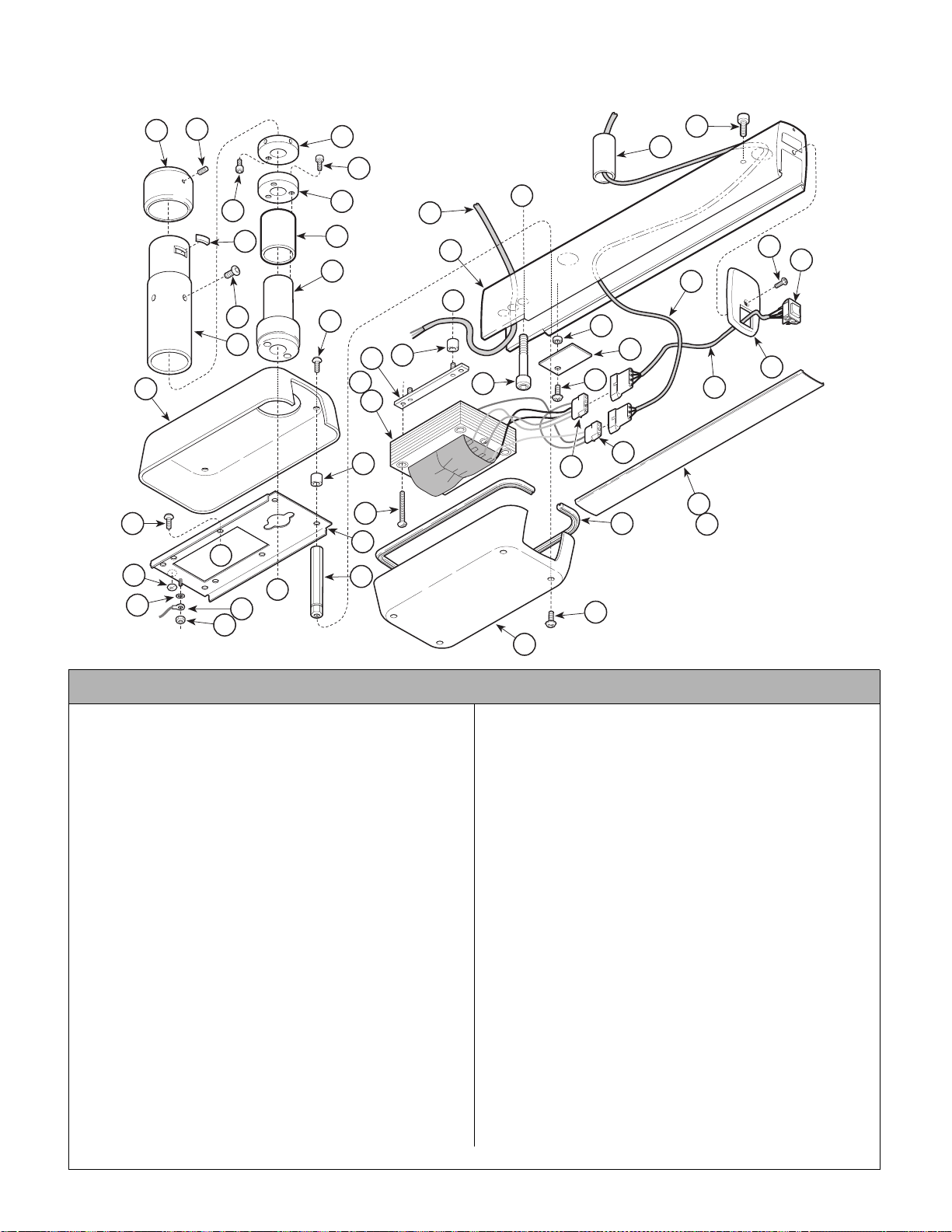
Track Light Fixed Arm Assembly
Return To Table Of Contents
152576
SECTION VI
PARTS L I ST
16
42
17
12
1
2
7
3
10
11
6
8
9
18
33
A
23
22
24
25
27
B
5
4
13
43
15
14
37
35
36
34
32
21
31
29
45
44
30
26
28
40
41
B
19
18
A
20
39
38
NOTE: This model
uses Sterling Grey
painted components.
AF2025
Used on Units with “LL” Serial Number Prefix
Item Part No. Description Qty. Item Part No. Description Qty.
152576 120 VAC Track Fixed Arm Assembly
(Includes Items 1 thru 46) ..................... 1
1 • 119827 • Screw.................................................. 1
2 • 121790-1 • Retaining Collar .................................. 1
3 • 121789-2 • Post Mount Pin ................................... 1
4 • 121769-1 • Mounting Post..................................... 1
5 • 121841 • Screw.................................................. 4
6 • 121780-2 • Keeper Ring........................................ 1
7 • 117558 • Screw.................................................. 1
8 • 117194 • Screw.................................................. 3
9 • 121781-2 • Stop Ring ............................................ 1
10 • 121782 • Bearing ............................................... 1
11 • 121770-1 • Pivot Bearing ...................................... 1
12 • 121744 • Bottom Light Transformer Cover......... 1
13 • 121730-1 • Carriage Bolt....................................... 4
14 • 121719 • Lower Cover Spacer ........................... 4
15 • 121466-2 • Light Transformer Chassis .................. 1
16 • 105816 • Screw.................................................. 4
17 • P14718 • External Tooth Washer ....................... 1
18 • 152600 • Track Transformer Cable..................... 1
19 • P507 • Hex Nut............................................... 1
20 • 121676 • Top Cover Standoff ............................. 4
21 • 102927 • 3 Circuit Connector (Not Shown) ........ 1
22 • 117505 • Bearing ............................................... 1
23 • 117636 • Stop Rotation Screw ........................... 1
Always Specify Model & Serial Number
24 • 121508-1 • Screw .................................................. 1
25 • 121758 • 3 Position Progressive Rocker Switch. 1
• 152508 • Blue Jumper (Not Shown) ................... 1
26 • 121764-1 • Rigid Arm Switch Cap .........................1
27 • 152501 • Intensity Switch Cable Assembly ........1
28 • 152499 • Light Arm Cable Assembly.................. 1
29 • 121719 • Spacer ................................................ 1
30 • 121786-2 • Spare Bulb Hole Plate .........................1
31 • 121142 • Screw .................................................. 1
32 • 121844 • Screw .................................................. 2
33 • 121860-1 • Fixed Arm............................................1
34 • 116420 • Vibration Isolator ................................. 4
35 • 152490 • Transformer Mounting Strip Assembly 2
36 • 152601 • 120 VAC Light Transformer Assembly.1
37 • P2446 • Screw .................................................. 4
38 • 121743 • Removable Light Transformer Cover... 1
39 • 120233 • Panel Screw ........................................ 4
40 • 121880-1 • Fixed Arm Cover .................................1
41 • 122078-2 • Cover Stop Pin (Not shown)................1
42 • 112504 • Ground Identification Label .................1
43 • 115896 • Cable Tie (Not Shown) ........................ 1
44 • 053-1222-00 • Trim Ring .............................................1
45 • 102793 • 3 Circuit Connector ............................. 1
46 • 115896 • Wire Ties (Not Shown) ..................... AR
© Midmark Corporation 2000 SF-1618 Printed in U.S.A.
Rev. 6/03
Page 6-28
Page 81
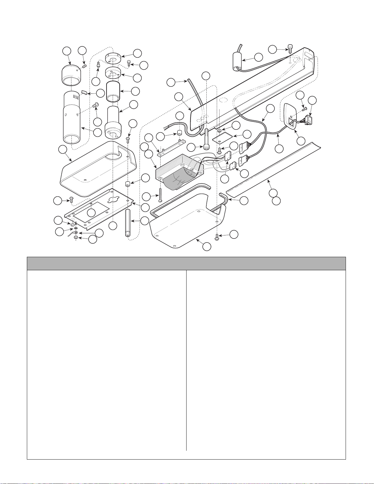
Track Light Fixed Arm Assembly
Return To Table Of Contents
152576-01 (120 vac) & 152612-01 (220 VAC)
SECTION VI
PARTS L I ST
16
42
17
12
1
2
7
3
10
11
6
8
9
18
33
A
23
22
24
25
27
B
5
4
13
43
14
15
37
35
36
34
32
21
31
29
45
44
30
26
28
40
41
B
19
18
A
20
39
38
NOTE: This model
uses Pebble Grey
painted components.
AF2025
Used on Units with “PH” Serial Number Prefix
Item Part No. Description Qty. Item Part No. Description Qty.
152576-01 120 VAC Track Fixed Arm Assembly
(Includes Items 1 thru 46) ..................... 1
152612-01 120 VAC Track Fixed Arm Assembly
(Includes Items 1 thru 46) ..................... 1
1 • 119827 • Screw.................................................. 1
2 • 121790-50 • Retaining Collar.................................. 1
3 • 121789-2 • Post Mount Pin ................................... 1
4 • 121769-50 • Mounting Post..................................... 1
5 • 121841 • Screw.................................................. 4
6 • 121780-2 • Keeper Ring........................................ 1
7 • 117558 • Screw.................................................. 1
8 • 117194 • Screw.................................................. 3
9 • 121781-2 • Stop Ring ............................................ 1
10 • 121782 • Bearing ............................................... 1
11 • 121770-50 • Pivot Bearing ...................................... 1
12 • 121744 • Bottom Light Transformer Cover......... 1
13 • 121730-50 • Carriage Bolt....................................... 4
14 • 121719 • Lower Cover Spacer ........................... 4
15 • 121466-2 • Light Transformer Chassis .................. 1
16 • 105816 • Screw.................................................. 4
17 • P14718 • External Tooth Washer ....................... 1
18 • 152600 • Track Transformer Cable..................... 1
19 • P507 • Hex Nut............................................... 1
20 • 121676 • Top Cover Standoff ............................. 4
21 • 102927 • 3 Circuit Connector (Not Shown) ........ 1
22 • 117505 • Bearing ............................................... 1
Always Specify Model & Serial Number
23 • 117636 • Stop Rotation Screw ........................... 1
24 • 121508-50 • Screw ..................................................1
25 • 121758 • 3 Position Progressive Rocker Switch. 1
• 152508 • Blue Jumper (Not Shown) ................... 1
26 • 121764-50 • Rigid Arm Switch Cap .........................1
27 • 152501 • Intensity Switch Cable Assembly ........1
28 • 152499 • Light Arm Cable Assembly.................. 1
29 • 121719 • Spacer ................................................ 1
30 • 121786-2 • Spare Bulb Hole Plate .........................1
31 • 121142 • Screw .................................................. 1
32 • 121844 • Screw .................................................. 2
33 • 121860-50 • Fixed Arm ............................................1
34 • 116420 • Vibration Isolator ................................. 4
35 • 152490 • Transformer Mounting Strip Assembly 2
36 • 152601 • 120 VAC Light Transformer Assembly.1
• 152611 • 120 VAC Light Transformer Assembly.1
37 • P2446 • Screw .................................................. 4
38 • 121743 • Removable Light Transformer Cover... 1
39 • 120233 • Panel Screw ........................................ 4
40 • 121880-50 • Fixed Arm Cover .................................1
41 • 122078-2 • Cover Stop Pin (Not shown)................1
42 • 112504 • Ground Identification Label .................1
43 • 115896 • Cable Tie (Not Shown) ........................ 1
44 • 053-1222-00 • Trim Ring .............................................1
45 • 102793 • 3 Circuit Connector ............................. 1
46 • 115896 • Wire Ties (Not Shown) ..................... AR
© Midmark Corporation 2000 SF-1618 Printed in U.S.A.
Rev. 6/03
Page 6-29
Page 82
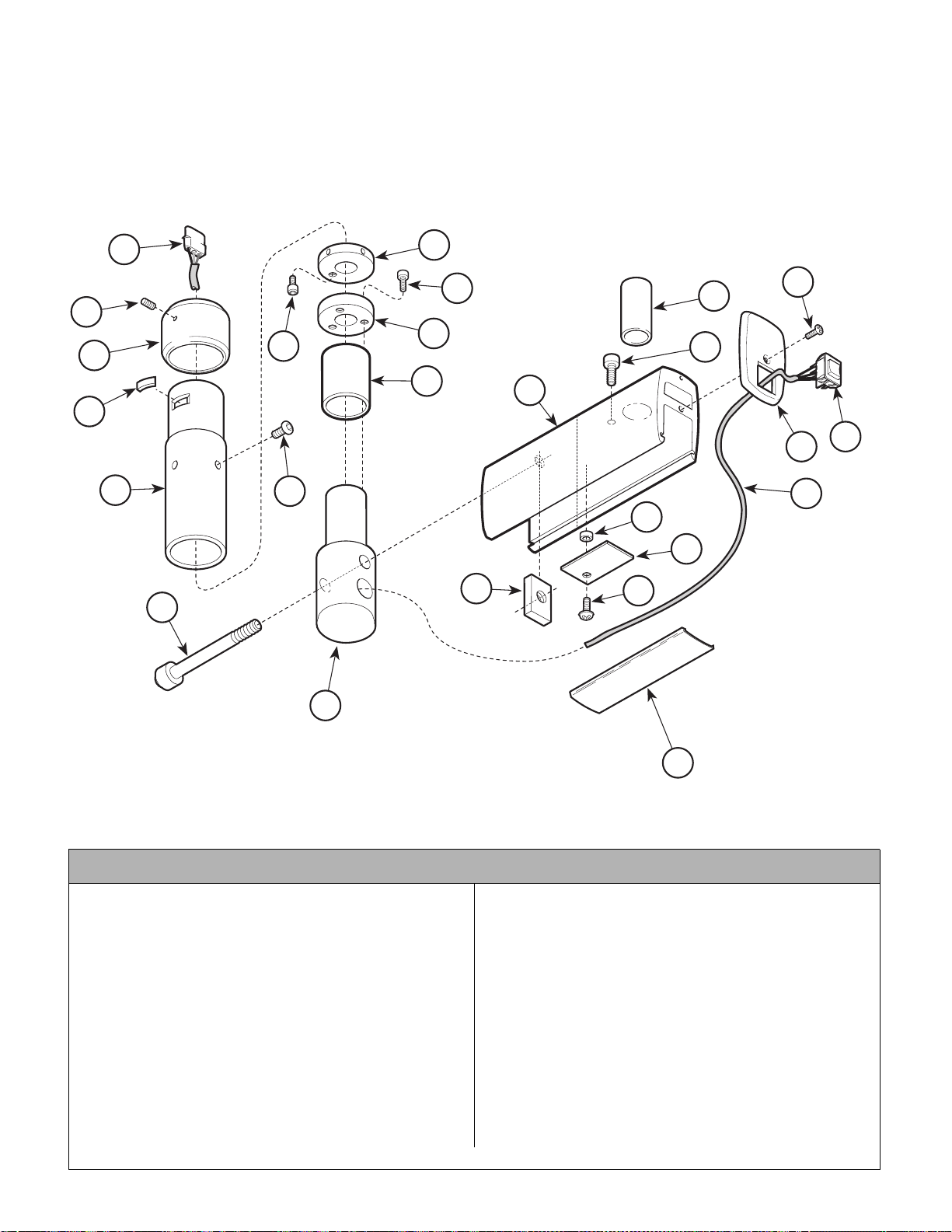
Cabinet Mount Fixed Arm Assembly
Return To Table Of Contents
152684
SECTION VI
PARTS LIST
25
6
8
14
16
1
9
2
7
10
13
15
3
17
18
4
5
19
20
21
23
22
12
11
NOTE: This model
24
uses Sterling Grey
painted components.
KA983100
Used on Units with “LL” Serial Number Prefix
Item Part No. Description Qty. Item Part No. Description Qty.
152684 Cabinet Mount Fixed Arm Assembly
(Includes Items 1 thru 25)..................... 1
1 • 11982 7 • Screw..................................................1
2 • 12179 0-1 • Retaining Collar.................................. 1
3 • 12178 9-2 • Post Mount Pin ................................... 1
4 • 12176 9-1 • Mounting Post..................................... 1
5 • 12184 1 • Screw..................................................4
6 • 12178 0-2 • Keeper Ring........................................ 1
7 • 11755 8 • Screw..................................................1
8 • 11719 4 • Screw..................................................3
9 • 12178 1-2 • Stop Ring............................................ 1
10 • 121782 • Bearing ............................................... 1
11 • 122015-1 • Cabinet Bearing Post.......................... 1
12 • 117519 • Screw (Apply Loctite #042-0024-00) .. 1
Always Specify Model & Serial Number
13 • 122014-1 • Cabinet Mount Fixed Arm ...................1
14 • 117505 • Bearing................................................1
15 • 117636 • Stop Rotation Screw ........................ ...1
16 • 121508-1 • Screw ..................................................1
17 • 121758 • 3 Position Progressive Rocker Switch.1
• 152508 • Blue Jumper (Not Shown)...................1
18 • 121764-1 • Rigid Arm Switch Cap .........................1
19 • 152685 • Light Arm Cable Assembly ..................1
20 • 121719 • Spacer ................................................1
21 • 121786-2 • Spare Bulb Hole Plate.........................1
22 • 121142 • Screw..................................................1
23 • 122019-1 • Bottom Arm Cover...............................1
24 • 117407-2 • Plate Nut .............................................1
25 • 102029 • Connector Plug - 9 Pin........................ 1
© Midmark Corporation 2000 SF-1618 Printed in U.S.A.
Rev. 5/03
Page 6-30
Page 83
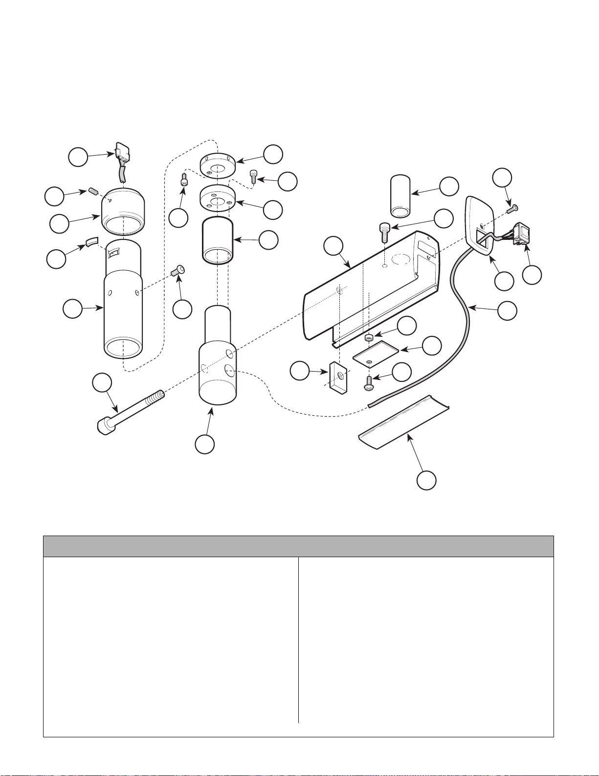
Cabinet Mount Fixed Arm Assembly
Return To Table Of Contents
152684-01
SECTION VI
PARTS LIST
25
6
8
14
16
1
9
2
7
10
13
15
3
17
18
4
5
19
20
21
23
22
12
11
NOTE: This model
24
uses Pebble Grey
painted components.
KA983100
Used on Units with “PH” Serial Number Prefix
Item Part No. Description Qty. Item Part No. Description Qty.
152684-01 Cabinet Mount Fixed Arm Asse m bly
(Includes Items 1 thru 25)..................... 1
1 • 11982 7 • Screw..................................................1
2 • 12179 0-50 • Retaining Collar.................................. 1
3 • 12178 9-2 • Post Mount Pin ................................... 1
4 • 12176 9-50 • Mounting Post..................................... 1
5 • 12184 1 • Screw..................................................4
6 • 12178 0-2 • Keeper Ring........................................ 1
7 • 11755 8 • Screw..................................................1
8 • 11719 4 • Screw..................................................3
9 • 12178 1-2 • Stop Ring............................................ 1
10 • 121782 • Bearing ............................................... 1
11 • 122015-50 • Cabinet Bearing Post.......................... 1
12 • 117519 • Screw (Apply Loctite #042-0024-00) .. 1
Always Specify Model & Serial Number
13 • 122014-50 • Cabinet Mount Fixed Arm ...................1
14 • 117505 • Bearing................................................1
15 • 117636 • Stop Rotation Screw ........................ ...1
16 • 121508-50 • Screw..................................................1
17 • 121758 • 3 Position Progressive Rocker Switch.1
• 152508 • Blue Jumper (Not Shown)...................1
18 • 121764-50 • Rigid Arm Switch Cap.........................1
19 • 152685 • Light Arm Cable Assembly ..................1
20 • 121719 • Spacer ................................................1
21 • 121786-2 • Spare Bulb Hole Plate.........................1
22 • 121142 • Screw..................................................1
23 • 122019-50 • Bottom Arm Cover...............................1
24 • 117407-2 • Plate Nut .............................................1
25 • 102029 • Connector Plug - 9 Pin........................ 1
© Midmark Corporation 2000 SF-1618 Printed in U.S.A.
Rev. 5/03
Page 6-31
Page 84
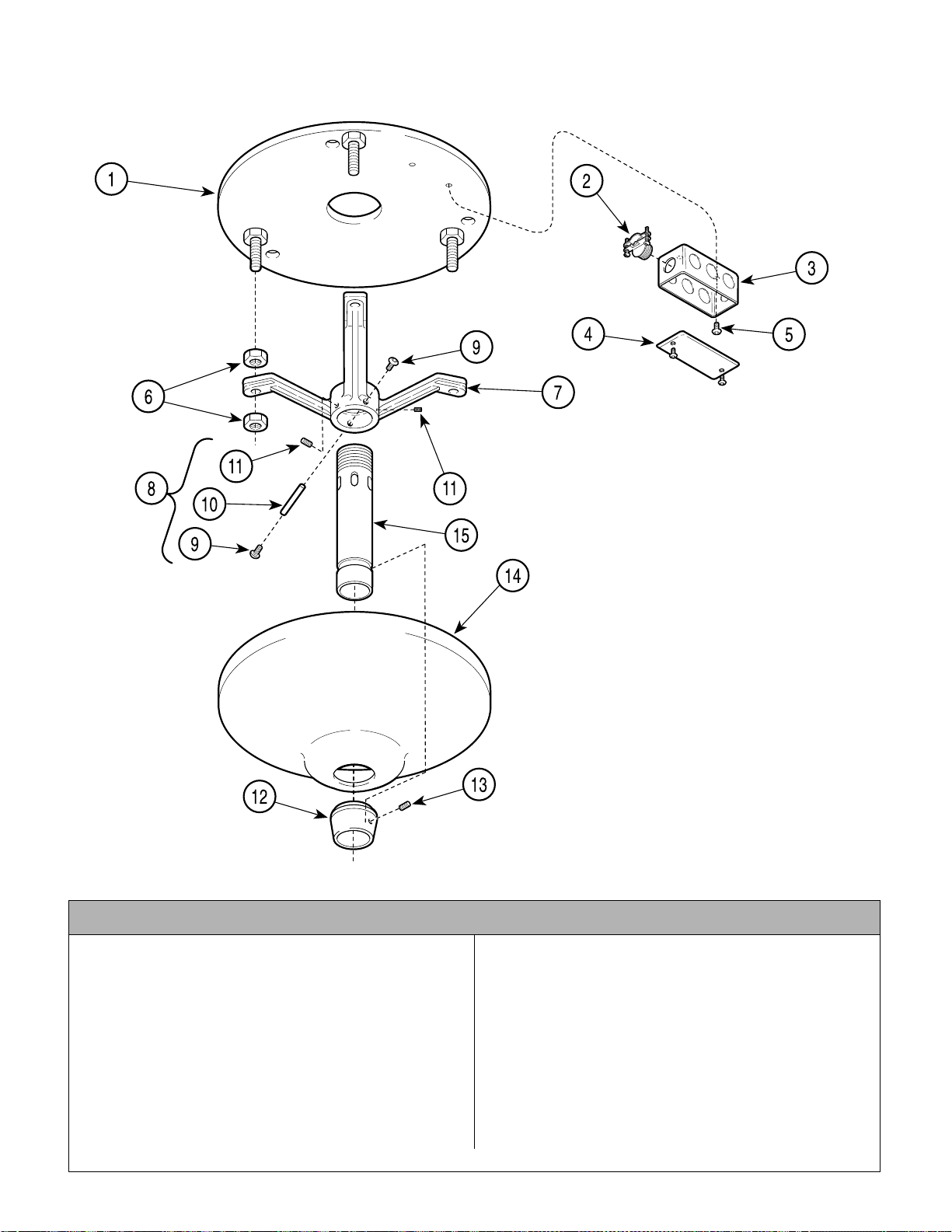
Ceiling Mounted Light Tripod Assembly
Return To Table Of Contents
149918
SECTION VI
PARTS LIST
Used on Units with “ LL” Serial Number Prefix
Item Part No. Description Qty. Item Part No. Description Qty.
149918 Tripod Assembly (Includ es I te m s 1 t hru
15 [Specify Length of Tube Item 15] ) ... 1
1 • 14991 9 • Leveling Plate..................................... 1
2 • 10298 0 • Romex Connector............................... 2
3 • 10295 8 • Electrical Junction Box........................ 1
4 • 12078 9-1 • Receptacle Cover............................... 1
5 • P15168 • Screw.................................................. 2
6 • 11951 3 • Hex Nut................ ............................... 6
7 • 11804 9 • Tripod.................................................. 1
8 • 96S203 • Hardware Kit (Include s I te m s
9 thru 13)............................................ 1
© Midmark Corporation 2000 SF-1618 Printed in U.S.A.
NOTE: This model
uses Sterling Grey
painted components.
AF2024
9 ••C5211 ••Screw................................................2
10 ••114437 ••Locking Pin.......................................1
11 ••106753 ••Set Screw .........................................3
12 ••117948-1 ••Canopy Collar ...................................1
13 ••106011 ••Set Screw .........................................1
14 • 118053 • Canopy................................................1
15 Supension Tube (Refer to “Ceiling
Mounted Li ght Assembly 152567
Elsewhere).............................................1
Always Specify Model & Serial Number
Page 6-32
Page 85
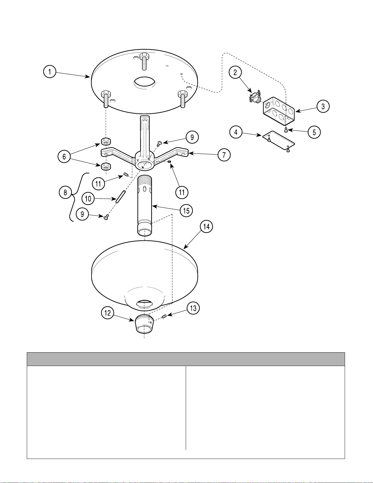
Ceiling Mounted Light Tripod Assembly
Return To Table Of Contents
149918-01
SECTION VI
PARTS LIST
Used on Units with “ PH” Serial Number Prefix
Item Part No. Description Qty. Item Part No. Description Qty.
149918-01 Tripod Assembly (Includes Items 1 thru
15 [Specify Length of Tube Item 15] ) ... 1
1 • 14991 9 • Leveling Plate..................................... 1
2 • 10298 0 • Romex Connector............................... 2
3 • 10295 8 • Electrical Junction Box........................ 1
4 • 12078 9-50 • Receptacle Cover...............................1
5 • P15168 • Screw.................................................. 2
6 • 11951 3 • Hex Nut................ ............................... 6
7 • 11804 9 • Tripod.................................................. 1
8 • 96S203 • Hardware Kit (Include s I te m s
9 thru 13)............................................ 1
© Midmark Corporation 2000 SF-1618 Printed in U.S.A.
NOTE: This model
uses Pebble Grey
painted components.
AF2024
9 ••C5211 ••Screw................................................2
10 ••114437 ••Locking Pin.......................................1
11 ••106753 ••Set Screw .........................................3
12 ••117948-50 ••Canopy Collar ...................................1
13 ••106011 ••Set Screw.........................................1
14 • 118053 • Canopy................................................1
15 Supension Tube (Refer to “Ceiling
Mounted Light Assembly 152567-01
Elsewhere).............................................1
Always Specify Model & Serial Number
Page 6-33
Page 86
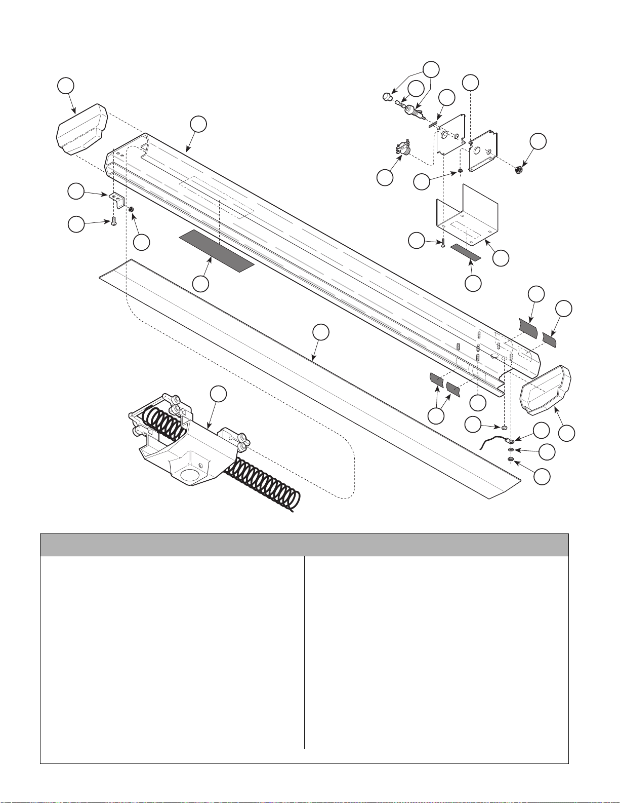
Track / Tolley Assembly
Return To Table Of Contents
SECTION VI
PARTS LIST
152603
1
3
4
22
21
A
20
2
25
23
5
19
17
18
6
16
15
14
8
7
A
9
10
NOTE: This model
uses Sterling Grey
painted components.
Used on Units with “ LL” Serial Number Prefix
Item Part No. Descriptio n Qty. Item Part No. Desc ri pt i on Qty.
152603 120 VAC Track / Trolley Assembly
(Includes Items 1 thru 25)......................1
1 • 1426 23 • End Cap...............................................2
2 • 1218 73-1 • Light Track...........................................1
3 • 1069 57 • Bracket.................................................2
4 • C4683 • Screw...................................................4
5 • 1069 58 • Bumper................................................2
6 • TPW1417 • Instruction Label..................................1
7 • 1526 08 • Trolle y Assemb ly (Ref er To Trolley
Assembly - 152608 Elsewhere)...........1
8 • 1213 27-1 • Track Light Cover................................. 1
9 • • Agency Compliance Label................AR
10 • 112504 • Ground Identification Label..................3
11 • 147232 • Wire Assembly.....................................1
12 • P14718 • Washer................................................3
13 • P14743 • Nut.......................................................3
Always Specify Model & Serial Number
14 • • Serial Number Label...........................1
15 • TP1376 • 120 VAC Rating Label.........................1
16 • 134555 • Caution Label.............. ........................1
17 • 108548 • Screw..................................................4
18 • 121866-1 • Enclosure Cover..................................1
19 • 122358 • Keps Hex Nut .....................................4
20 • 121292 • Fuse Rating Label ...............................1
21 • 111541 • 15 AMP Fuse ......................................1
22 • 122541 • Fuse Holder (Includes Nuts)...............1
23 • 102980 • Connector ...........................................2
24 • 121865-1 • Track Enclosure...................................1
25 • 120236 • Hole Plug ............................................1
26 • TPW1392 • Light Pre-Installation M anual
(not shown)............................ ...........1
27 • 177404 • Tape (not shown)......................... 4.8 ft.
11
13
1
12
AF2032
© Midmark Corporation 2000 SF-1618 Printed in U.S.A.
Page 6-34
Page 87
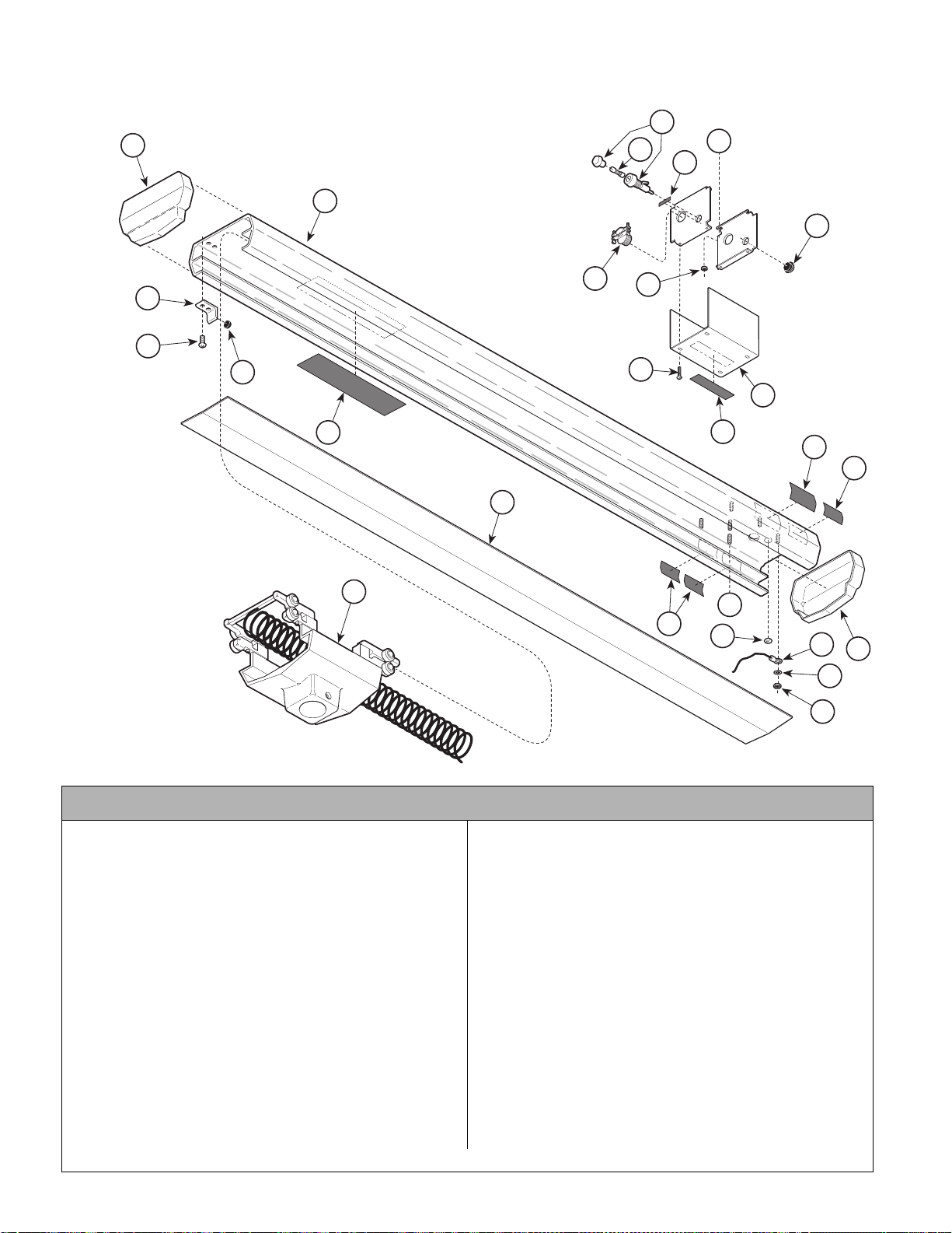
Track / Tolley Assembly
Return To Table Of Contents
152603-01(120 VAC), 152609-01 (220 VAC)
22
1
21
2
A
20
SECTION VI
PARTS LIST
25
3
4
NOTE: This model
uses Pebble Grey
painted components.
23
5
19
17
18
6
16
15
14
8
7
A
9
10
11
13
1
12
Used on Units with “ PH” Serial Number Prefix
Item Part No. Descriptio n Qty. Item Part No. Desc ri pt i on Qty.
152603-01 120 VAC Track / Trolley Assembly
(Includes Items 1 thru 25)......................1
152609-01 220 VAC Track / Trolley Assembly
(Includes Items 1 thru 25)......................1
1 • 1426 23 • End Cap...............................................2
2 • 1218 73-50 • Light Track ...........................................1
3 • 1069 57 • Bracket.................................................2
4 • C4683 • Screw...................................................4
5 • 1069 58 • Bumper................................................2
6 • TPW1417 • Instruction Label..................................1
7 • 1526 08-01 • Trolley Assembly (Refer To Trolley
Assembly - 152608-01 Elsewhere)......1
8 • 1213 27-50 • Track Light Cover.................................1
9 • • Agency Compliance Label................AR
10 • 112504 • Ground Identification Label..................3
11 • 147232 • Wire Assembly.....................................1
12 • P14718 • Washer................................................3
13 • P14743 • Nut.......................................................3
© Midmark Corporation 2000 SF-1618 Printed in U.S.A.
AF2032
14 • • Serial Number Label...........................1
15 • TP1376 • 120 VAC Rating Label.........................1
• TP1377 • 220 VA C Rating Label......................... 1
16 • 134555 • Caution Label.............. ........................1
17 • 108548 • Screw..................................................4
18 • 121866-50 • Enclosure Cover..................................1
19 • 122358 • Keps Hex Nut .....................................4
20 • 121292 • Fuse Rating Label (120 VAC Units) .... 1
• TP1418 • Fuse Rating La be l ( 220 VAC Units)....1
21 • 111541 • 15 AMP Fuse (120 VAC Units) ............1
• 119987 • 3 AMP Fuse (220 VAC Units)..............1
22 • 122541 • Fuse Holder (Includes Nuts)...............1
23 • 102980 • Connector ...........................................2
24 • 121865-50 • Track Enclosure...................................1
25 • 120236 • Hole Plug ............................................1
26 • TPW1392 • Light Pre-Installation M anual
(not shown)............................ ...........1
27 • 177404 • Tape (not shown)......................... 4.8 ft.
Always Specify Model & Serial Number
Page 6-35
Page 88
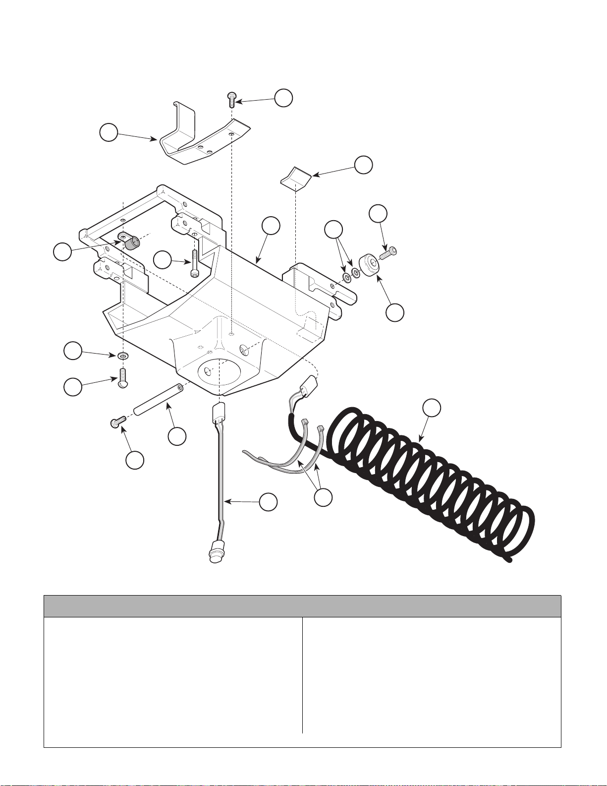
Tolley Assembly
Return To Table Of Contents
152608
1
SECTION VI
PARTS LIST
2
3
4
7
6
9
10
11
12
NOTE: This model
uses Sterling Grey
painted components.
8
5
16
13
14
15
Used on Units with “LL” Serial Number Prefix
Item Part No. Description Qty. Item Part No. Description Qty.
152608 Trolley Assembly (Includes
Items 1 thru 25)..................................... 1
1 • 107152 • Wire Cover.......................................... 1
2 • 102162 • Screw.................................................. 3
3 • P16614 • Felt Pad (Cut to [4] .75” Length) ......... 1
4 • 116598 • Screw (Apply Loctite # 186504).......... 8
5 • 122072 • Ball Bearing (Use Kit 152733)............ 8
6 • 104573 • Nylon Washer................................... 16
7 • 149286 • Painted Track Trolley........................... 1
© Midmark Corporation 2000 SF-1618 Printed in U.S.A.
Rev. 7/03
AF2033
8 • 106937 • Screw..................................................4
9 • 121877 • Cable Clamp .......................... .............1
10 • P12575 • Washer................................................1
11 • P17928-2 • Screw .................................................. 1
12 • C5211 • Screw .................................................. 2
13 • 114437 • Lock Pin .............................................. 1
14 • 152607 • Har ness As sembly..............................1
15 • 115896 • Cable Tie ............................................ 2
16 • 152606 • Coil Cord Assembly.............................1
Always Specify Model & Serial Number
Page 6-36
Page 89
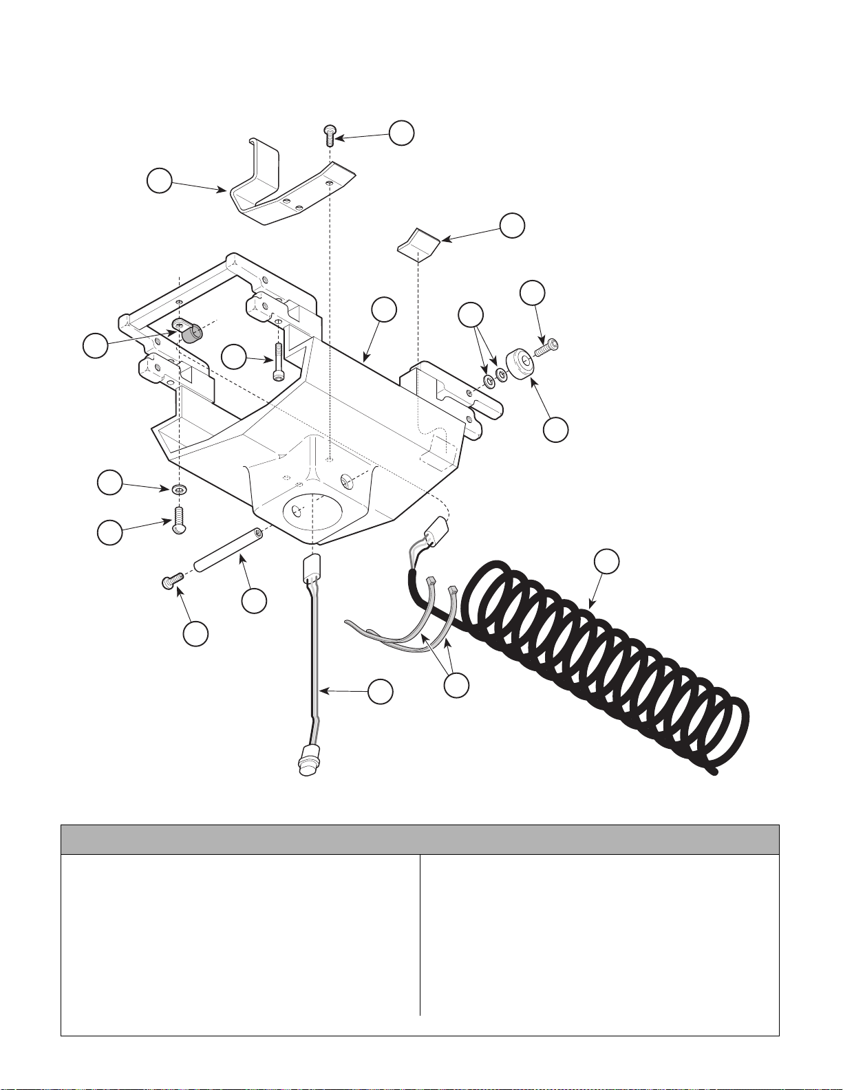
Tolley Assembly
Return To Table Of Contents
152608-01
1
SECTION VI
PARTS LIST
2
3
4
7
6
9
10
11
12
NOTE: This model
uses Pebble Grey
painted components.
8
5
16
13
14
15
Used on Units with “PH” Serial Number Prefix
Item Part No. Description Qty. Item Part No. Description Qty.
152608-01 Trolley Assembly (Inclu des
Items 1 thru 25)..................................... 1
1 • 10715 2 • Wire Cover.......................................... 1
2 • 10216 2 • Screw..................................................3
3 • P16614 • Felt Pad (Cut to [4] .75” Length) ......... 1
4 • 11659 8 • Screw (Apply Loctite # 186504).......... 8
5 • 12207 2 • Ball Bearing (Use Kit 152733) ............ 8
6 • 10457 3 • Nylon Washer................................... 16
7 • 14928 6-50 • Painted Track Trolley........................... 1
© Midmark Corporation 2000 SF-1618 Printed in U.S.A.
Rev. 7/03
AF2033
8 • 10693 7 • Screw ..................................................4
9 • 12187 7 • Cable Clamp .................... ...................1
10 • P12575 • Washer................................................1
11 • P17928-2 • Screw..................................................1
12 • C5211 • Screw ..................................................2
13 • 114437 • Lock Pin ..............................................1
14 • 152607 • Harness Assembly..............................1
15 • 115896 • Cable Tie ............................... .............2
16 • 152606 • Coil Cord Assembly.............................1
Always Specify Model & Serial Number
Page 6-37
Page 90
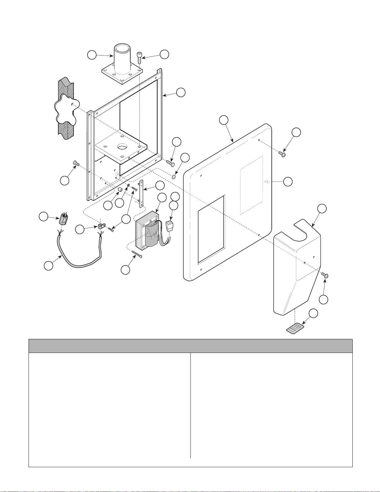
Wall Mount Assembly
Return To Table Of Contents
152544
SECTION VI
PARTS LIST
18
15
12
7
1
2
4
16
20
21
20
8
3
6
14
13 19
10
9
17
NOTE: This model
uses Sterling Grey
11
5
22
painted components.
Used on Units with “LL” Serial Number Prefix
Item Part No. Description Qty. Item Part No. Description Qty.
152544 120 VAC Wall Mount Assembly
(Includes Items 1 thru 21)...................... 1
1 • 152539-1 • Wall Mount Light Frame ...................... 1
2 • 121801 • Wall Mount Cover................................ 1
3 • 121802 • Post Mount Cover ............................... 1
4 • 121981 • Screw.................................................. 4
5 • 121127-1 • Screw .................................................. 2
6 • 152870 • Post Mount Assembly ......................... 1
7 • 111911 • Screw.................................................. 8
8 • 015-1400-00 • 120 VAC Light Transformer Assembly 1
9 • 121655 • Cable Clamp ....................................... 1
10 • 120199 • Screw .................................................. 2
11 • P2446 • Screw ................................................. 4
Always Specify Model & Serial Number
12 • 152490 • Strip Assembly ....................................2
13 • 116420 • Vibration Isolator .................................4
14 • P14718 • External Tooth Washer ........................1
15 • 120385 • Screw ..................................................4
16 • 101317 • Lag Screw ...........................................8
17 • 149418 • 120 VAC Power Cord Assembly ..........1
18 • 110994 • 120 VAC Power Cord Plug ..................1
19 • 102014 • 9 Pin Receptacle (Refer to
“Wiring Diagram” Elsewhere) .............. 1
20 • 112504 • Ground Identification Label ................. 1
21 • TP1395 • 120 VAC Wiring Diagram Label ...........1
22 • TP1376 • UL/CE Rating Plate-120V Units) .........1
• TP1377 • UL/CE Rating Plate-220V Units) ......... 1
23 • 115896 • Cable Tie (Not Shown) ........................1
AF2022
© Midmark Corporation 2000 SF-1618 Printed in U.S.A.
2/02
Page 6-38
Page 91
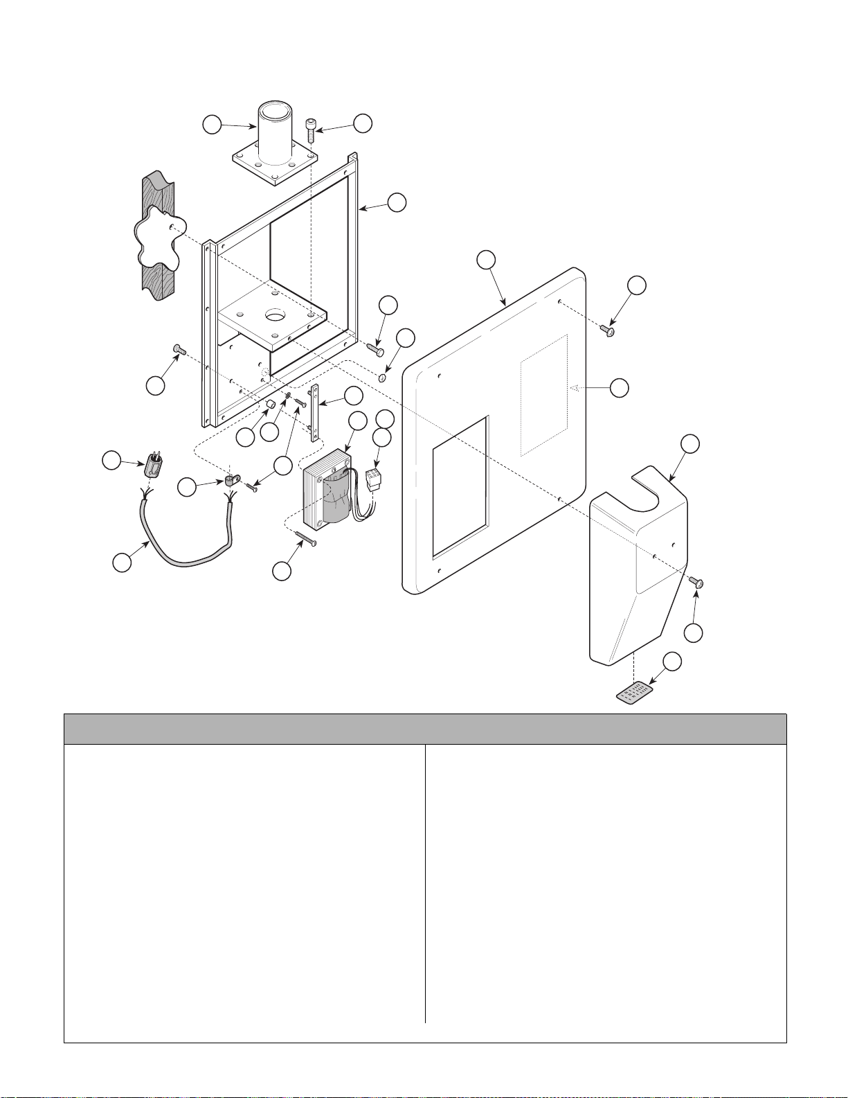
Wall Mount Assembly
Return To Table Of Contents
SECTION VI
PARTS LIST
152544-01(120 VAC) & 152549-01 (220 VAC)
18
15
12
7
1
2
4
16
20
21
20
8
3
6
14
13 19
10
9
17
11
NOTE: This model
uses Pebble Grey
painted components.
5
22
Used on Units with “PH” Serial Number Prefix
Item Part No. Description Qty. Item Part No. Description Qty.
152544-01 120 VAC Wall Mount Asse m bly
(Includes Items 1 thru 21)...................... 1
152549-01 220 VAC Wall Mount Asse m bly
(Includes Items 1 thru 21)...................... 1
1 • 152539-50 • Wall Mount Light Frame ......................1
2 • 121801-01 • Wall Mount Cover................................ 1
3 • 121802 • Post Mount Cover...............................1
4 • 121981-50 • Screw..................................................4
5 • 121127--50 • Screw..................................................2
6 • 152870-01 • Post Mount Assembly.........................1
7 • 111911 • Screw .................................................. 8
8 • 015-140 0- 00 • Light Transformer Assembly (120 VAC)1
• 152559 • Light Transformer Assembly (220 VAC)1
9 • 121655 • Cable Clamp.......................................1
10 • 120199 • Screw.................................................. 2
11 • P2446 • Screw ................................................. 4
12 • 152490 • Strip Assembly.................................... 2
Always Specify Model & Serial Number
13 • 116420 • Vibration Isolator ................... ..............4
14 • P14718 • External Tooth Washer........................1
15 • 120385 • Screw ..................................................4
16 • 101317 • Lag Screw ...........................................8
17 • 149418-01 • Power Cord Assembly (120 VAC)........1
• 149433 • Power Cord Assembly (220 VAC)........1
18 • 110994 • Power Cord Plug (120 VAC)................1
• 120374 • Power Cord Plug (220 VAC)................1
19 • 102014 • 9 Pi n Receptacle (Refer to
“Wiring Diagram” Elsewhere) ..............1
20 • 112504 • Ground Identification Label.................1
21 • TP1 395 • Wiring Diagram Label (120 VAC) ........1
• TP1 396 • Wiring Diagram Label (220 VAC) ........1
22 • TP1376 • UL/CE Rating Plate (120 VAC)............1
• TP1377 • UL/CE Rating Plate (220 VAC)............1
23 • 115896 • Cable Tie (Not Shown)........................1
AF2022
© Midmark Corporation 2000 SF-1618 Printed in U.S.A.
7/02
Page 6-39
Page 92
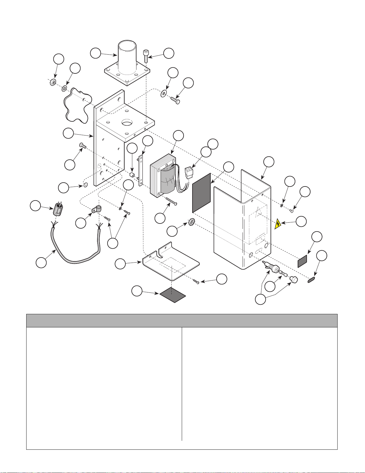
Cabinet Mount Assembly
Return To Table Of Contents
152683
SECTION VI
PARTS LIST
26
1
27
7
28
3
2
4
5
6
NOTE: This model
uses Sterling Grey
painted components.
21
10
29
11
13
12
22
30
14
18
15
9
8
22
24
23
16
25
20
23
19
17
18
AF2031
Used on Units with “LL” Serial Number Prefix
Item Part No. Description Qty. Item Part No. Description Qty.
152683 120 VAC Cabinet Mou nt A ss em bly
(Includes Items 1 thru 29)..................... 1
1 • C1269 • Hex Nut ............................ .................. 4
2 • C3724 • Washer............................................... 4
3 • 152870 • Post Mount Assembly.........................1
4 • 111911 • Screw.................................................. 8
5 • 117649 • Washer............................................... 4
6 • C3283 • Screw.................................................. 4
7 • 152681-1 • Cabinet Mount Light Frame ................ 1
8 • 116420 • Vibration Isolator................................. 4
9 • 152490 • Strip Assembly.................................... 2
10 • 015- 1400-00 • 120 VAC Light Transformer Assembly 1
11 • 102014 • 9 Circuit Connector ............................1
12 • TP1395 • 120 VAC Wiring Diagram Label.......... 1
13 • 122016-1 • Cabinet Transformer Cover................. 1
14 • TPW1459 • High Voltage Label..............................1
Always Specify Model & Serial Number
15 • TPW1464 • Warning Label.....................................1
16 • TPW1465 • 15 AMP Fuse Label.............................1
17 • 111541 • 15 AMP Fuse ...................................... 1
18 • 122541 • Fuse Holder (Includes Nut) .................2
19 • TP1 376 • Model “L” 102 VAC Ra ting Label .........1
20 • 122540-1 • Fixed Panel .........................................1
21 • P2446 • Screw..................................................4
22 • P14718 • Lockwasher.........................................2
23 • 121337-2 • Screw.................................................. 4
24 • 121655 • Cable Clamp .......................................1
25 • 153109 • Cord Assembly....................................1
26 • 110994 • Power Plug .......................................... 1
27 • 112504 • Ground Identification Label.................1
28 • 122018 • Screw .................................................. 1
29 • 115896 • Cable Tie (Not Shown)................. .......1
30 • 105480 • Screw..................................................2
© Midmark Corporation 2000 SF-1618 Printed in U.S.A.
Rev. 10/01
Page 6-40
Page 93
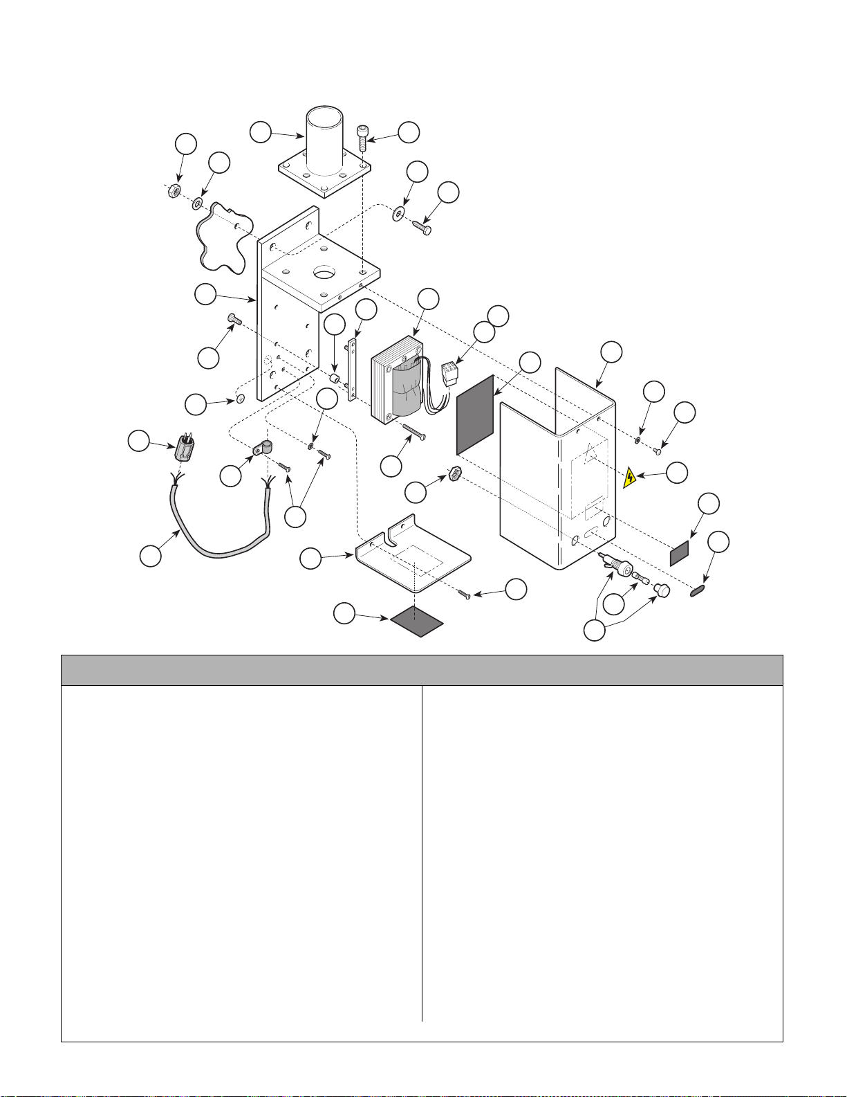
Cabinet Mount Assembly
Return To Table Of Contents
SECTION VI
PARTS LIST
152682-01 (220 VAC) & 152683-01 (120 VAC)
26
3
4
1
2
5
6
NOTE: This model
uses Pebble Grey
27
7
28
24
23
22
9
8
10
29
11
12
21
18
painted components.
13
22
30
14
15
16
25
20
23
19
17
18
AF2031
Used on Units with “PH” Serial Number Prefix
Item Part No. Description Qty. Item Part No. Description Qty.
152682-01 220 VAC Cabinet Mount Assembly
(Includes Items 1 thru 29)..................... 1
152683-01 120 VAC Cabinet Mount Assembly
(Includes Items 1 thru 29)..................... 1
1 • C1269 • Hex Nut .................................. ............ 4
2 • C3724 • Washer ............................................... 4
3 • 15287 0-01 • Post Mount Assembly......................... 1
4 • 11191 1 • Screw..................................................8
5 • 11764 9 • Washer ...............................................4
6 • C3283 • Screw.................................................. 4
7 • 15268 1-50 • Cabinet Mount Light Fra m e ................ 1
8 • 11642 0 • Vibration Isolator.................................4
9 • 15249 0 • Strip Assembly.................................... 2
10 • 015-1400-00 • Light Transforme r Assembly (120 VAC)1
• 152550 • Light Transformer Assembly (220 VAC)1
11 • 102014 • 9 Circuit Connector ............................ 1
12 • TP1395 • 120 VAC Wiring Diagra m Label .......... 1
13 • 122016-50 • Cabinet Transformer Cover................. 1
14 • TPW1459 • High Voltage Label.............................. 1
15 • TPW1464 • Warning Label..................................... 1
16 • TPW1465 • 15 AMP Fuse Label............................ 1
Always Specify Model & Serial Number
17 • 111541 • 15 AMP Fuse ......................... .............1
18 • 122541 • Fuse Holder (Includes Nut).................2
19 • TP1376 • Model “L” 120 VAC Rating Label .........1
• TP1377 • Model “L” 220 VAC Rating Label ......... 1
20 • 122540-50 • Fixed Panel .........................................1
21 • P2446 • Screw..................................................4
22 • P14718 • Lockwasher.........................................2
23 • 121337-2 • Screw..................................................4
24 • 121655 • Cable Clamp (120 VAC) ......................1
• 121654 • Cable Clamp (220 VAC)......................1
25 • 153109 • Cord Assembly (120 VAC)...................1
• 153098 • Cord Assembly (220 VAC)...................1
26 • 110994 • Power Plug (120 VAC).........................1
• 120374 • Powe r Plug (220 VAC).........................1
27 • 112504 • Ground Identification Label.................1
28 • 122018 • Screw ..................................................1
29 • 115896 • Cable Tie (Not Shown)........................1
30 • 105480 • Screw ..................................................2
31 • 153110 • 120 VAC Fuse Cable (Not Shown)......1
• 153099 • 220 VAC Fuse Cable (Not Shown)......1
© Midmark Corporation 2000 SF-1618 Printed in U.S.A.
Rev. 10/01
Page 6-41
Page 94
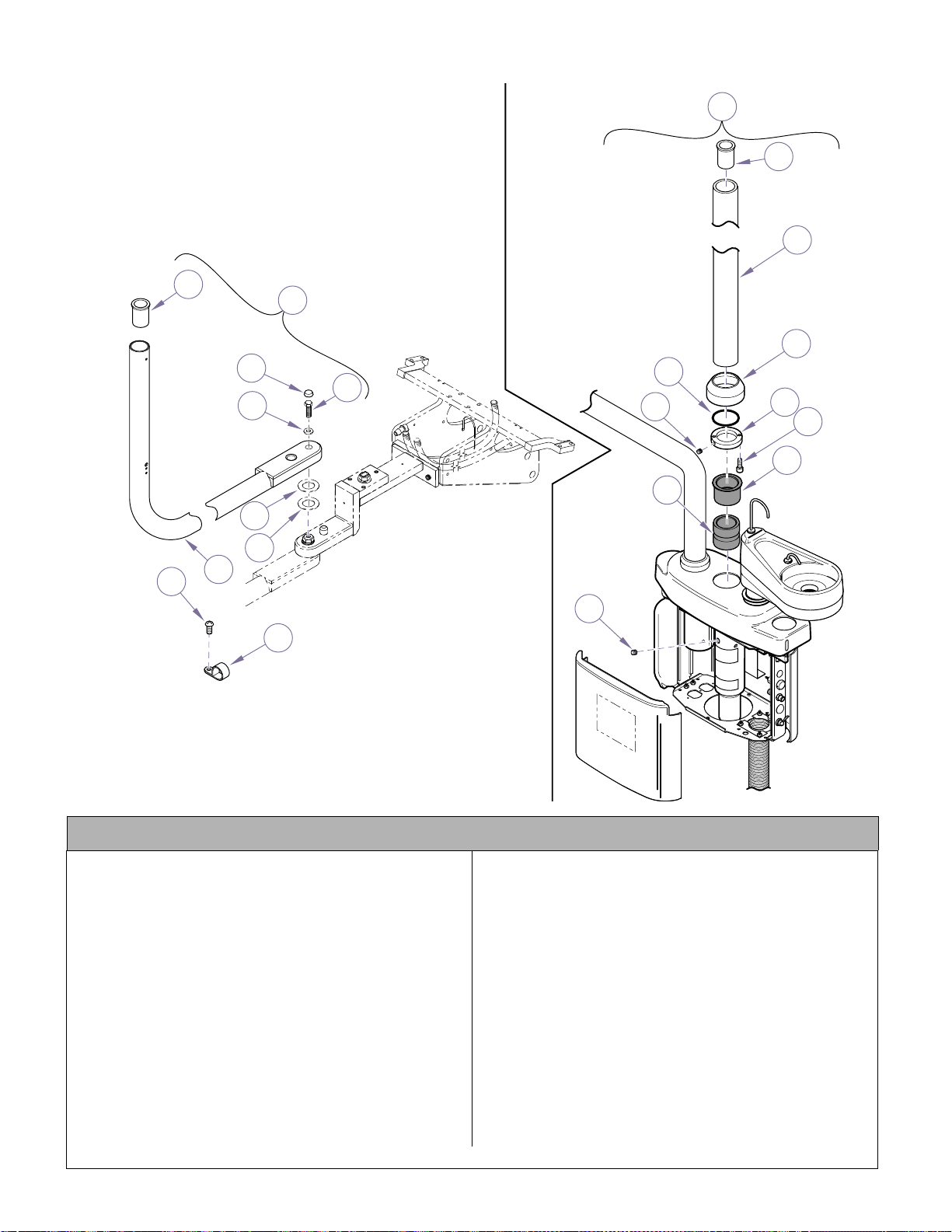
Light Arm Mounting Components
Return To Table Of Contents
8
1
2
3
4
5
16
SECTION VI
PARTS LIST
11
12
13
14
15
17
18
19
20
6
7
9
21
10
NOTE: This model
uses Sterling Grey
painted components.
KA933100
Used on Units with “ LL” Serial Number Prefix
Item Part No. Description Qty. Item Part No. Description Qty.
1 153122 Light Arm Assembly (For LR
Mounted Arm) .....................................1
2 • 12259 5 • Cover, Light Bolt..................................1
3 • 12255 1 • Screw ..................................................1
4 • 15526 9 • Washer................................................1
5 • 12255 5 • Washer, Steel......................................1
6 • 12255 6 • Washer, Delrin.....................................1
7 • 15310 0-1 • Light Arm.............................................1
8 • 12179 6 • Light Bearing.......................................1
9 • 10548 0 • Screw ..................................................1
10 • 121655 • Cable Clamp .......................................1
11 152919 Light Arm Assembly (For Console
Mounted Arm w/Model L Light............1
153040 Light Arm Assembly (For Console
Mounted Arm w/Un i versal Light or
Competitor ‘s Light.............................. 1
Always Specify Model & Serial Number
12 • 121796 • Light Bearing (Used On 152919)........ 1
121049-2 Light Bearing (Used On 153040)........ 1
13 • 121797-1 • Post, Arm (Used On 152919) ............. 1
122389-1 Post, Arm (Used On 153040).............1
14 • 122338-1 • Trim Ring............................................. 1
15 • 122344 • O-Ring ................................................ 1
16 • 122161 • Set Screw ........................................... 2
17 • 122337-2 • Arm Pivot Collar.................................. 1
18 • 120652 • Screw.................................................. 2
19 • 122336 • Pivot Bearing Upper............................ 1
20 • 122339 • Pivot Bearing Lower............................ 1
21 • 120913 • Set Screw ........................................... 2
© Midmark Corporation 2000 SF-1618 Printed in U.S.A.
Page 6-42
Page 95
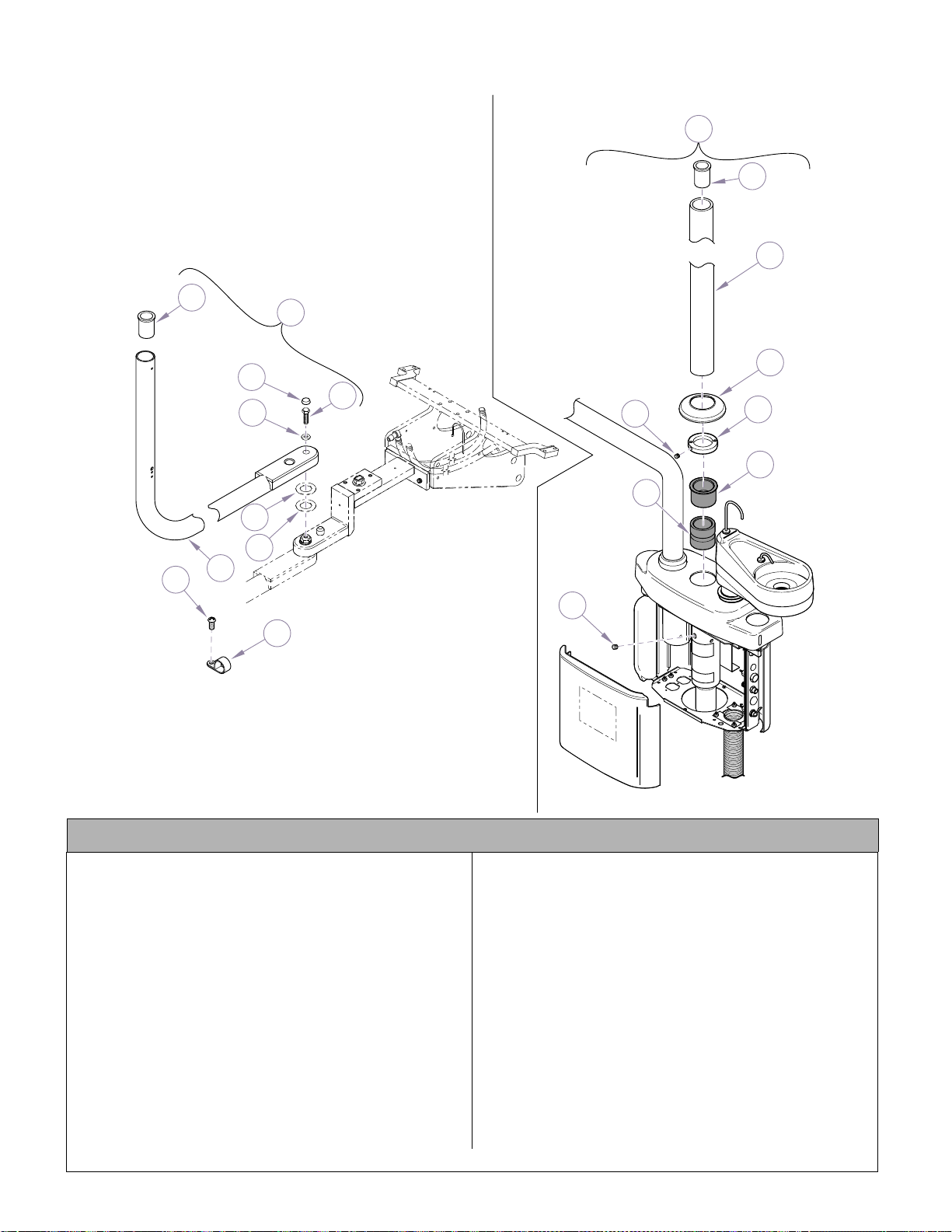
Light Arm Mounting Components
Return To Table Of Contents
SECTION VI
PARTS LIST
11
12
13
8
7
9
NOTE: This model
uses Pebble Grey
painted components.
1
14
2
3
4
15
16
17
18
5
6
19
10
Used on Units with “PH” Serial Number Prefix
Item Part No. Description Qty. Item Part No. Description Qty.
1 153122-01 Light Arm Assembly (For LR
Mounted Arm) .....................................1
2 • 122595 • Cover, Light Bolt..................................1
3 • 122551 • Screw..................................................1
4 • 155269 • Washer................................................1
5 • 122555 • Washer, Steel......................................1
6 • 122556 • Washer, Delrin ..................................... 1
7 • 153100-50 • Light Arm.............................................1
8 • 121796 • Light Bearing.......................................1
9 • 105480 • Screw..................................................1
10 • 121655 • Cable Clamp .......................................1
11 152919-01 Light Arm Ass em bly (For Console
Mounted Arm w/Model L Light............1
153040-01 Light Arm Assembly (For Console
Mounted Arm w/Un i versal Light or
Competitor ‘s Light..............................1
© Midmark Corporation 2000 SF-1618 Printed in U.S.A.
Rev. 5/02
KA933101i
12 • 121796 • Light B earing (Used On 152919-01)... 1
121049-2 Light Bearing (Used On 153040)........ 1
13 • 121797-50 • Post, Arm (Used On 152919-01)........ 1
122389-1 Post, Arm (Used On 153040-01)........ 1
14 • 053-1221-00 • Trim Ring............................................. 1
15 • 122161 • Set Screw ........................................... 2
16 • 122337-2 • Arm Pivot Collar................ .................. 1
17 • 122336 • Pivot Bearing Upper................ ............ 1
18 • 122339 • Pivot Bearing Lower................ ............ 1
19 • 120913 • Set Screw ........................................... 2
Always Specify Model & Serial Number
Page 6-43
Page 96
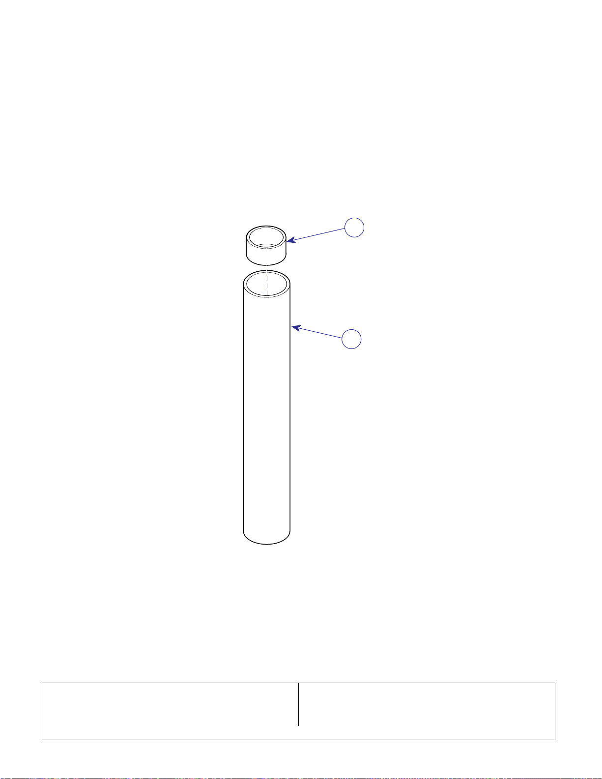
Light Mounting Post Kit
Return To Table Of Contents
48.0 in. (121.9 cm)
SECTION VI
PARTS LIST
2
1
NOTE: This model
uses Sterling Grey
painted components.
Item Part No. Description Qty. Item Part No. Description Qty.
002-0633-00 Light Mounting Post Kit, 48 in.
(Includes items 1 & 2)
© Midmark Corporation 2000 SF-1618 Printed in U.S.A.
KA939900
1 • 1217 76-1 • Mou nting Post..................................... 1
2 • 1217 96 • Bearing ............................................... 1
Always Specify Model & Serial Number
Page 6-44
Page 97

COMMENTS
Return To Table Of Contents
The Technical Publications Department of Midmark
Corporation takes pride in its publications. We are sure
that our manuals will fill all of your needs when you are
performing scheduled maintenance, servicing, or
repairs on a Midmark product.
Page(s) and Paragraph(s) Needing Changed:
Description of Error or Desired Change:
However, if you find any errors or feel that there should
be a change, addition, or deletion to a manual, please
let us know!
Please fax or mail a copy of this completed comment
sheet to:
Midmark Corporation
ATTN: Techni cal Publicat io ns Depa rtment
60 Vista Drive
Versailles, Ohio 45380
Fax: (937) 526-5542
© Midmark Corporation 2000 SF-1621 Page 7-1 Printed in U.S.A.
Page 98
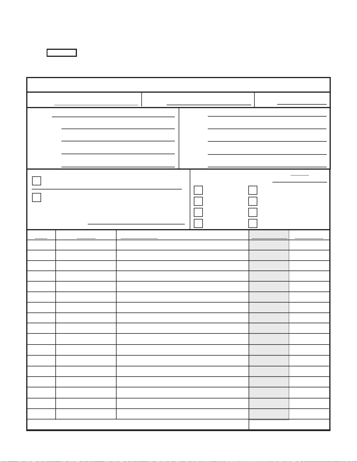
FAX ORDERING FORM
Return To Table Of Contents
(SERVICE PARTS ONLY)
NOTES:
• ALL BLOCKED AREAS MUST BE COMPLETED.
• USE FOR NON-WARRANTY FAX ORDERS ONLY. WARRANTY ORDERS MUST BE TELEPHONED IN (1-800-MIDMARK).
ATTENTION: SERVICE DEPARTMENT FAX#: 877-249-1793
ACCT #: P.O. #: DATE:
NAME: SHIP TO:
ADDRESS:
CITY, ST.:
CONTACT:
PHONE:
NON-EMERGENCY ORDER - TO SHIP WITHIN 72 HOURS IF
PART(S) IN STOCK.
EMERGENCY ORDER - TO SHIP WITHIN 24 HOURS IF PART(S)
IN STOCK (IF ORDER IS RECEIVED BEFORE 1:30 P.M. E.S.T).
SEND NOTIFICATION IF PARTS ARE NOT AVAILABLE TO SHIP
WITHIN 24 HOURS VIA
E-MAIL OR FAX TO:
METHOD OF SHIPMENT
UPS
NEXT DAY A.M.
NEXT DAY P.M.
2ND DAY
GROUND
FED EX
NEXT DAY A.M.
NEXT DAY P.M.
2ND DAY
ECONOMY
OTHER
QTY. PART # DESCRIPTION (SPECIFY COLOR OF ITEM IF APPLICABLE) COLOR CODE PRICE/PER
© Midmark Corporation 2000 Rev. 1/03 Page 7-2 Printed in U.S.A.
TOTAL COST: $
Page 99

Return To Table Of Contents
Page 100

Midmark Corporation
Return To Table Of Contents
60 Vista Drive
P.O. Box 286
Versailles, Ohio 45380-0286
937-526-3662
Fax 937-526-5542
midmark.com
© Midmark Corporation - 2003 Printed in U.S.A.
Subject To Change Without Notice
 Loading...