

Page 1
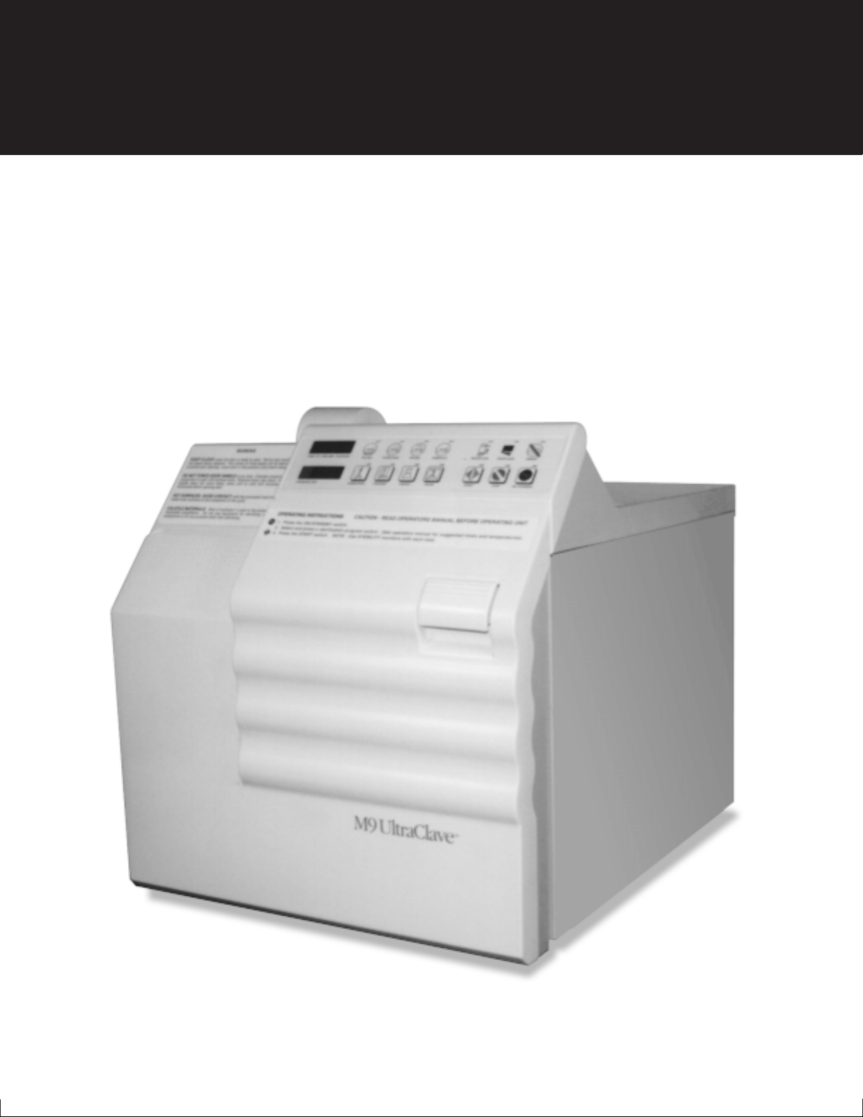
M9
Go To Table Of Contents
Sterilizer
Used on units with
Serial Number Prefixes:
CZ, DA, DB, DX, DY, FD,
FK, LA, FL and OM
Self-Contained
Steam Sterilizer
Service and
Parts Manual
SF-1572 Part No. 004-0083-00 Rev. G (1/02)
FOR USE BY MIDMARK
TRAINED TECHNICIANS
ONLY
Page 2

Go To Table Of Contents
Page 3

TABLE OF CONTENTS
Section/Paragraph Page
IMPORTANT INSTRUCTIONS
General Safety Instructions ........................................ ii
Safety Alert Symbols .................................................. ii
Warranty Instructions.................................................. ii
SECTION I GENERAL INFORMATION
1.1 Scope of Manual ......................................... 1-1
1.2 How to Use Manual .................................... 1-1
1.3 Description of Sterilizer ............................... 1-1
1.4 Specifications ............................................. 1-4
1.5 Parts Replacement Ordering ...................... 1-4
1.6 Special Tools .............................................. 1-5
SECTION II TESTING AND TROUBLESHOOTING
2.1 Operational Test .......................................... 2-1
2.2 Troubleshooting Procedures ....................... 2-3
SECTION III SCHEDULED MAINTENANCE
3.1 Scheduled Maintenance ............................. 3-1
SECTION IV MAINTENANCE/SERVICE
INSTRUCTIONS
4.1 Introduction ................................................. 4-1
4.2 Top Cover Removal / Installation ................ 4-1
4.3 Right Hand Side Panel Removal /
Installation .............................................. 4-1
4.4 Left Hand Side Panel Removal /
Installation .............................................. 4-2
4.5 Back Panel Removal/Installation................. 4-3
4.6 Base Inspection Cover Removal /
Installation .............................................. 4-3
4.7 Bellows Assembly Removal / Installation .... 4-4
4.8 Condensing Tank Water Level Sensor
Removal / Installation ............................. 4-5
4.9 Temperature Sensor Assembly
Removal / Installation ............................. 4-6
4.10 Pressure Vessel Water Level Sensor
Removal / Installation ............................. 4-6
4.11 Vent Solenoid Removal / Installation ........... 4-7
4.12 Fill Solenoid Removal / Installation ............. 4-9
4.13 Control PC Board Removal / Installation ... 4-10
4.14 Door Switch Removal / Installation ........... 4-13
4.15 Pulse Solenoid Removal / Installation ....... 4-13
4.16 Thermostat Removal / Installation............. 4-14
Section/Paragraph Page
4.17 Wire Tray Rack and Tray Plate
Removal / Installation ........................... 4-15
4.18 Heating Element and Gasket
Removal / Installation ........................... 4-15
4.19 Filter Removal / Installation ....................... 4-16
4.20 Door Gaskets Removal / Installation......... 4-17
4.21 Display PC Board Removal / Installation .. 4-17
4.22 Condensing Tank Assembly
Removal / Installation ........................... 4-18
4.23 Pressure Relief Valve Removal /
Installation ............................................. 4-19
4.24 Pressure / Temperature Potentiometers
Adjustments ......................................... 4-20
4.25 Display PC Board Lamp / Display /
Button Check........................................ 4-23
4.26 Pressure Relief Valve Check .................... 4-24
4.27 Dry Cycle Dip Switches Adjustment........... 4-25
SECTION V SCHEMATICS AND DIAGRAMS
5.1 Wiring Diagram ........................................... 5-1
5.2 Flow Diagram ............................................. 5-4
5.3 Pressure / Temperature Chart ..................... 5-5
SECTION VI PARTS LIST
6.1 Introduction ................................................. 6-1
6.2 Description of Columns ................................ 6-1
6.3 Torque Specifications and Important
Assembly Notes ...................................... 6-1
Pictorial Index ............................................. 6-2
Main Enclosure Components .................... 6-3.*
Plumbing and Sensor Components .......... 6-4.*
Pressure Vessel Components .................... 6-5
Manifold Components ............................... 6-6.*
Electrical Components .............................. 6-7.*
Control PC Board...................................... 6-8.*
Labels and Decals ...................................... 6-9
Printer Components.................................. 6-10
Racks, Trays, and Cleaner ..................... 6-11.*
Packaging ................................................. 6-12
COMMENTS ........................................................... 7-1
FAX ORDERING FORM.......................................... 7-2
(*) Indicates that there has been a serial number break for the illustration
and that there are additional point page(s) following the original page.
© Midmark Corporation 1998 SF-1572 Page i Printed in U.S.A.
Page 4

IMPORTANT INSTRUCTIONS
Return To Table Of Contents
General Safety Instructions
Safety First: The primary concern of Midmark
Corporation is that this sterilizer is maintained with
the safety of the patient and staff in mind. To assure
that services and repairs are completed safely and
correctly, proceed as follows:
(1) Read this entire manual before performing any
services or repairs on this sterilizer.
(2) Be sure you understand the instructions
contained in this manual before attempting to
service or repair this sterilizer.
Safety Alert Symbols
Throughout this manual are safety alert symbols that
call attention to particular procedures. These items are
used as follows:
DANGER
A DANGER is used for an imminently
hazardous operating procedure,
practice, or condition which, if not correctly
followed, will result in loss of life or serious
personal injury.
NOTE
A NOTE is used to amplify an operating procedure,
practice or condition.
Warranty Instructions
Refer to the Midmark “Limited Warranty” printed in the
Installation and Operation Manual for warranty information. Failure to follow the guidelines listed below will
void the warranty and/or render the M9 sterilizer
unsafe for operation.
• In the event of a malfunction, do not attempt to
operate the sterilizer until necessary repairs have
been made.
• Do not attempt to disassemble sterilizer, replace
malfunctioning or damaged components, or perform
adjustments unless you are one of Midmark’s
authorized service technicians.
• Do not substitute parts of another manufacturer
when replacing inoperative or damaged components.
Use only Midmark replacement parts.
WARNING
A WARNING is used for a potentially
hazardous operating procedure,
practice, or condition which, if not correctly
followed, could result in loss of life or serious
personal injury.
CAUTION
A CAUTION is used for a potentially
hazardous operating procedure, practice,
or condition which, if not correctly followed, could
result in minor or moderate injury. It may also be
used to alert against unsafe practices.
EQUIPMENT ALERT
An EQUIPMENT ALERT is used for an
imminently or potentially hazardous
operating procedure, practice, or condition which, if
not correctly followed, will or could result in serious,
moderate, or minor damage to unit.
© Midmark Corporation 1998 SF-1572 Page ii Printed in U.S.A.
Page 5

SECTION I
Return To Table Of Contents
GENERAL INFORMATION
!"#$%&'(%
)"'"*+,(%'-&*.+$%&'
1.1 Scope of Manual
This manual contains detailed troubleshooting, scheduled maintenance, maintenance, and service instructions for the M9 Sterilizers. This manual is intended to
be used by Midmark’s authorized service technicians.
1.2 How to Use Manual
A. Manual Use When Performing Scheduled Mainte-
nance.
(1) Perform inspections and services listed in
Scheduled Maintenance Chart (Refer to
para 3.1).
(2) If a component is discovered to be faulty or out
of adjustment, replace or adjust component in
accordance with Maintenance/Service Instructions (Refer to para 4.1).
B. Manual Use When Sterilizer Is Malfunctioning And
Cause Is Unknown.
(1) Perform an operational test on sterilizer (Refer
to para 2.1).
(2) Perform troubleshooting procedures listed in
Troubleshooting Guide (Refer to para 2.2).
(3) If a component is discovered to be faulty or out
of adjustment, replace or adjust component in
accordance with Maintenance/Service Instructions (Refer to para 4.1).
C. Manual Use When Damaged Component Is Known.
(1) Replace or adjust component in accordance
with Maintenance/Service Instructions (Refer to
para 4.1).
1.3 Description Of Sterilizer
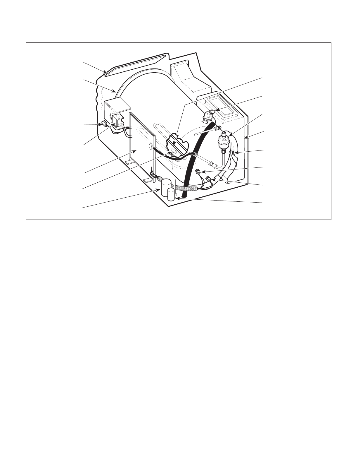
A. General Description (See Figure 1-1).
The M9 Sterilizers are designed to sterilize instruments.
The major components of the sterilizer consist of a
pressure vessel, condensing tank assembly, heating
element, temperature sensor assembly, condensing
tank water level sensor (early M9 units only), pressure
vessel water level sensor, pulse solenoid, thermostat,
door switch, control PC board, fill solenoid, vent solenoid, bellows assembly, display PC board, and a
pressure relief valve.
B. Theory of Operation (See Figures 5-1 and 5-2).
Theory Of Operation:
Power is supplied to the control PC board when the
sterilizer is plugged in. At this time, the control PC
board will flash the error lamp and display “E 001”. This
is normal and occurs when the sterilizer is first plugged
in or if a power outage has occurred.
When the ON/STANDBY switch is pressed, the error
lamp extinguishes and the program switches are
enabled. The program lamps flash and the ON/
STANDBY indicator lamp illuminates.
The operator determines the desired cycle and selects
the cycle by pressing either: UNWRAPPED,
POUCHES, LIQUIDS, OR PACKS button. Upon
selecting the desired cycle, the control PC board sets
the specific time and temperature parameters for that
cycle into memory. These settings are alternately
displayed on the TIME/TEMP display. Note: The
control PC board will continue to use the same parameters on subsequent cycles until a new type of cycle is
selected.
The operator presses the START button which signals
the control PC board to initiate the cycle.
The control PC board continuously monitors for an open
door condition from the time the START button is
pressed until the start of the drying cycle. It does this
by monitoring the door switch for continuity. If no
continuity is detected after a cycle has been started, the
control PC board will stop the cycle and illuminate the
DOOR AJAR indicator. The DOOR AJAR indicator will
continue to flash until continuity is sensed or until the
STOP or ON/STANDBY button is pressed. Or, if the
door is closed and continuity is sensed, the control PC
board continues the cycle.
© Midmark Corporation 1998 SF-1572 Page 1-1 Printed in U.S.A.
Page 6
!"#$%&'(%
Return To Table Of Contents
)"'"*+,(%'-&*.+$%&'
DISPLAY PC
BOARD
PRESSURE
VESSEL
DOOR
SWITCH
HEATING
ELEMENT
PRESSURE
RELIEF VALUE
BELLOWS
ASSEMBLY
CONDENSING
TANK ASSEMBLY
PULSE
SOLENOID
CONTROL PC
BOARD
THERMOSTAT
FILL
SOLENOID
Figure 1-1. Major Components
On early units (units with an old style control PC board
which has EPROM version M or before) which have a
condensing tank water level sensor, the control PC
board monitors the condensing tank water level when
the sterilizer door is closed. The control PC board
monitors the water level in the condensing tank during
this portion of the cycle only, and it performs this
monitoring by checking for continuity between the
condensing tank water level sensor and the chassis.
Water touches the sensor to complete a ground circuit,
signaling the control PC board that the water level is
sufficient and the cycle may be continued. Otherwise,
the control PC board will stop the cycle and flash the
WATER LOW indicator until water is sensed by the
sensor, the STOP button is pressed, or the ON/
STANDBY button is pressed. On later units (units with
old style control PC board which has EPROM version N
or after or new style control PC board) which do not
have the condensing tank water level sensor, the
control PC board monitors the pressure vessel water
level sensor to determine if a low water condition in the
condensing tank exists. If the pressure vessel water
CONDENSING TANK
WATER LEVEL SENSOR
(early M9 only)
TEMPERATURE
SENSOR ASSEMBLY
PRESSURE VESSEL
WATER LEVEL SENSOR
VENT
SOLENOID
MA207604
level sensor does not sense water within 5 minutes of
starting the FILLING portion of the cycle, the control PC
board stops the cycle, illuminates the WATER LOW
indicator and starts sounding a beeper signal.
The control PC board illuminates the FILLING indicator
and energizes the fill solenoid which allows water to
flow from the condensing tank to the pressure vessel.
The control PC board controls the water level in the
pressure vessel by monitoring the pressure vessel
water level sensor for continuity. When water completes the ground circuit between the pressure vessel
water level sensor and the chassis, the control PC
board de-energizes the fill solenoid.
The control PC board extinguishes the FILLING indicator lamp and illuminates the STERILIZING indicator
lamp. During this portion of the cycle, temperature and
pressure in the pressure vessel are continuously
monitored until the drying portion of the cycle begins. A
precision integrated circuit temperature sensor potted
inside a brass thermowell is used to monitor the tem-
© Midmark Corporation 1998 SF-1572 Page 1-2 Printed in U.S.A.
Page 7

!"#$%&'(%
Return To Table Of Contents
)"'"*+,(%'-&*.+$%&'
perature inside the pressure vessel. A PC board
mounted piezoresistive pressure sensor, connected by
plumbing to the pressure vessel, is used to monitor the
pressure in the pressure vessel.
The control PC board energizes the heating element to
begin heating the water in the pressure vessel. The
temperature in the pressure vessel is displayed on the
display PC board. As the water begins to boil, air is
bled off through the bellows assembly into the condensing tank. The pressure in the pressure vessel is not
displayed until the temperature in the pressure vessel
reaches 208 °F (98 °C). When the bellows assembly
senses pure steam flowing through it (which is around
215 °F), the valve in the bellows assembly closes,
allowing the pressure in the pressure vessel to build.
When the temperature corresponding to the cycle
selected is reached, the control PC board de-energizes
the heating element and begins to count down the
remaining time left in the cycle. The remaining time is
now displayed on the display PC board instead of the
temperature. During this portion of the cycle, the
control PC board regulates the pressure vessel temperature/pressure by energizing and de-energizing the
heating element as necessary. The programmed
temperatures are the minimum values, and the temperature during the cycle is regulated approximately 2
°F (1.1 °C) above those minimum values.
When the cycle’s set time has elapsed, the control PC
board de-energizes the heating element and energizes
the vent solenoid, unless the liquids cycle was selected.
If the liquids cycle was selected, the control PC board
de-energizes the heating element, but does not energize the vent solenoid until the temperature in the
pressure vessel drops to 223 °F (106 °C).
The control PC board monitors the pressure in the
pressure vessel until it drops to 0.7 psi (4.8 kPa). At
that time, the control PC board goes into a 35 second
delay. At the end of the delay, the control PC board
sounds a series of five beeper signals and energizes
the pulse solenoid for 500 ms (except for the liquids
cycle on a sterilizer that contains an old style control PC
board with EPROM version H or before. If old style
control PC board after version H or if it is a new style
control PC board, the door will open at the end of the
liquids cycle also.), which allows the door to open to the
vent position. The control PC board then de-energizes
the vent solenoid. The control PC board (on units with
old style control PC board which has EPROM version J
or after or new style control PC board), the control PC
board checks that the door switch switches back to its
normally open position after the door opens. Checking
the door switch position ensures that the door switch is
not stuck closed, which would mislead the operator to
think the door was closed when it was actually ajar.
During the sterilizing portion of the cycle, the control PC
board continuously monitors the pressure sensor,
temperature sensor, door switch, STOP button, and the
ON/STANDBY button. If the pressure or temperature
exceeds preset limits or the status of the door switch,
STOP button, or ON/STANDBY button changes, the
control PC board de-energizes the heating element and
initiates an error sequence.
When an error sequence is initiated, the control PC
board energizes the vent solenoid, flashes the ERROR
indicator, sounds a beeper signal, and displays the
error code, corresponding to the cause of the error, on
the TEMP/TIME display. When the pressure in the
pressure vessel drops to 0.7 psi (4.8 kPa), the control
PC board delays 35 seconds. The control PC board
then de-energizes the vent solenoid and stops sounding
the beeper signal. The ERROR indicator lamp continues to flash and the error code continues to be displayed until the STOP or ON/STANDBY button is
pressed.
The control PC board illuminates the DRYING indicator
and extinguishes the STERILIZING indicator. The
control PC board begins a countdown of 30 minutes
and displays this time on the TEMP/TIME display. The
control PC board energizes the heating element for 45
seconds, delays two minutes, energizes the heating
element for 30 seconds, delays two minutes, energizes
the heating coil for a predetermined duration (the
duration can be set on the dip switch assembly for
different time intervals), and then delays for two more
minutes. The control PC board continues to energize
the heating element for xx seconds followed by a two
minute delay for the rest of the drying portion of the
cycle. On units with new style control PC boards, there
is a dip switch assembly which contains two switches
for "dry cycle element duration". There are four possible
combinations for these two switches, which results in
setting the heating element duration during the drying
cycle; they are repeat interval setting #1, setting #2,
setting #3, and setting #4. Setting #1 is shortest repeat
interval, setting #2 is longer, setting #3 is longer yet,
and setting #4 is the longest repeat interval. This
function was added to allow adjustment of "dry cycle
element duration on units which are overheating during
drying cycle. The unit comes factory set at the repeat
© Midmark Corporation 1998 SF-1572 Page 1-3 Printed in U.S.A.
Page 8

!"#$%&'(%
Return To Table Of Contents
)"'"*+,(%'-&*.+$%&'
interval setting #3. If the sterilizer contains an old style
control PC board with EPROM version L or after or a
new style control PC board, the control PC board
monitors the chamber for excessive pressure during the
drying cycle, which indicates that the door did not open
properly. If excessive pressure is detected, the drying
cycle is stopped. After 30 minutes have elapsed, the
control PC board illuminates the COMPLETE indicator,
extinguishes the DRYING indicator, and sounds the
beeper signal seven times. If the liquids cycle was
selected, the DRYING indicator does not illuminate, the
heating element does not energize, and the COMPLETE
indicator illuminates. If the STOP button is pressed
during the drying portion of the cycle, a new cycle can
be initiated.
Several safety checks are present to prevent the
pressure vessel from exceeding safe pressure and
temperature limits. The control PC board limits the
pressure and temperature from exceeding 34.5 psi (238
kPa) and 277 °F (136 °C) respectively. A pressure
relief valve prevents the pressure from exceeding 35
psi (241 kPa) on older units and 40 psi (275.7 kPa) on
newer units. A bi-metallic thermostat shuts off power to
the control PC board if the pressure vessel temperature
exceeds 295 °F (146 °C).
1.4 SPECIFICATIONS
Factual data for the sterilizer is provided in Table 1-1.
Table 1-1. Specifications
Description Data
Dimensions (overall):
Length ............................................... 19 in (470 mm)
Width (depth) ....................................... 15 in (381 mm)
Height .................................................. 16 in (406 mm)
Electrical Requirements:
100 VAC Unit ...............................100 VAC 50 - 60 HZ,
15 amp, single phase
115 VAC Unit ......................110 - 120 VAC 50 - 60 HZ,
15 amp, single phase
230 VAC Unit ......................220 - 240 VAC 50 - 60 HZ,
7 amp, single phase
Power Consumption:
100 VAC Unit ......................................... 1425 WATTS,
15 amps @ 100 VAC
115 VAC Unit ......................................... 1425 WATTS,
12 amps @ 120 VAC
230 VAC Unit ......................................... 1500 WATTS,
7 amps @ 240 VAC
Recommended Circuit:
A separate (dedicated) circuit is recommended for
this sterilizer. The sterilizer
to an electrical circuit with other appliances or
equipment unless the circuit is rated for the additional load.
Chamber Pressure:
Operating ......................... 27 - 31 psi (186 - 215 kPa)
Minimum Before Door Is Released....... 0.7 psi (5 kPa)
Maximum Before Safety Valve
Opens (older units). .......................... 35 psi (241 kPa)
Maximum Before Safety Valve
Opens (newer units). ..................... 40 psi (275.7 kPa)
Chamber Temperature (Operating):
Unwrapped Cycle ................ 272-273 °F (133-134 °C)
Pouches Cycle .................... 272-273 °F (133-134 °C)
Liquids Cycle ....................... 252-253 °F (122-123 °C)
Packs Cycle ........................ 252-253 °F (122-123 °C)
Maximum Before Thermostat
Energizes ........................................... 295 °F (146 °C)
should not
be connected
Shipping Carton....................... 22 in x 17.75 in x 18 in
Weight:
Reservoir Empty..................................... 70 lb (32 kg)
Reservoir Full ......................................... 77 lb (35 kg)
With Shipping Carton .............................. 78 lb (36 kg)
Water Reservoir Capacity................ Approx. 7/8 gallon
© Midmark Corporation 1998 SF-1572 Page 1-4 Printed in U.S.A.
(56 cm x 45 cm x 46 cm)
(3.31 Liters to full mark)
1.5 Parts Replacement Ordering
If a part replacement is required, order the part directly
from the factory as follows:
(1) Refer to Figure 1-2 to determine the location of
the model number and serial number of the
sterilizer and record this data. There are
different letter prefixes which proceed the serial
number, depending on the configuration of the
unit. These prefixes are very important and are
needed to order the proper parts.
Page 9

!"#$%&'(%
Return To Table Of Contents
)"'"*+,(%'-&*.+$%&'
MODEL NUMBER
SERIAL NUMBER
MA2071-01
Figure 1-2. Model Number / Serial Number Location
(2) Refer to the Parts List to determine the item
numbers of the parts, part numbers of the
parts, descriptions of the parts, and quantities
of parts needed and record this data (Refer to
para 6.1).
NOTE
Ask the Purchasing Department of the company that
owns the sterilizer for this information. Otherwise,
this information may be obtained from the dealer that
sold the sterilizer.
(4) Call Midmark with the recorded information and
ask for the Medical Services Department. See
back cover of this manual for the phone number
or use the Fax Order Form (See page 7-2 for
Fax Order Form).
1.6 Special Tools
Table 1-2 lists all the special tools needed to repair the
sterilizer, describes how to obtain the special tools, and
describes the purpose of each special tool.
(3) Determine the installation date of the sterilizer
and record this data.
Table 1-2. Special Tool List
Description of Special Tool
Digital Multimeter (must be
capable of displaying 3 digits)
Water Level Sensor Wrench Midmark Corp.
3/32 in. Diameter Punch Commercially Available Any Type Used to remove / install two roll pins which secure
Pressure Gauge Test Harness Midmark Corp.
Manufacturer's
Name / Address / Phone
Commercially Available Any Type Used to check probes, switches, and connections
60 Vista Drive
Versailles, Ohio 45380
(513) 526-3662
60 Vista Drive
Versailles, Ohio 45380
(513) 526-3662
Manufacturer's
Part Number
for proper function by performing continuity
checks.
050-2324-00 Used to hold fitting in place so the nut that holds
water level sensor can be loosened / tightened.
door switch in place or roll pin which secures latch
lever to pulse solenoid.
002-0372-00 Used to check the pressure in the pressure vessel
during a cycle to diagnose malfunctions and / or
adjust the pressure range potentiometer to a
correct setting.
Purpose of Special Tool
© Midmark Corporation 1998 SF-1572 Page 1-5 Printed in U.S.A.
Page 10

!"#$%&'(%
Return To Table Of Contents
)"'"*+,(%'-&*.+$%&'
© Midmark Corporation 1998 SF-1572 Page 1-6 Printed in U.S.A.
Page 11
$"!$%')(+'/($*&01,"!2&&$%')
Return To Table Of Contents
SECTION II
TESTING AND TROUBLESHOOTING
!"#$%&'(%%
2.1 Operational Test
In order to effectively diagnose the malfunction of the
M9 sterilizer, it is necessary to perform an operational
test as follows:
WARNING
Refer to the operator manual for
complete instructions on operating the
sterilizer. Failure to do so could result in severe
personal injury.
(1) Place the sterilizer on a level surface.
(2) Remove right hand side panel (Refer to
para 4.3).
(3) Plug the sterilizer into a properly grounded
receptacle, capable of supplying correct and
adequate power to operate this sterilizer.
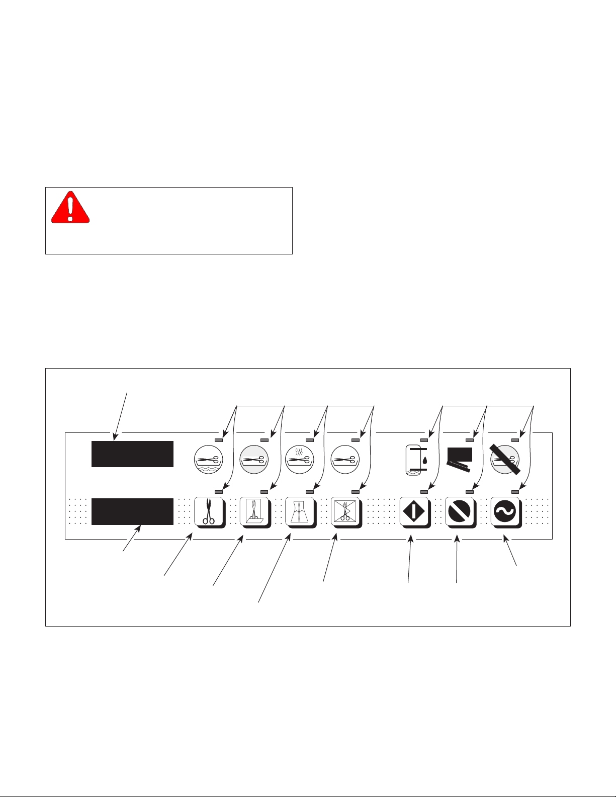
TEMP / TIME DISPLAY
LAMP
(4) Open sterilizer door.
(5) Press and hold down the LIQUIDS and PACKS
buttons simultaneously while connecting the
power cord to the sterilizer (See Figure 2-1).
Release the LIQUIDS and PACKS buttons.
(6) Observe the display PC board lamps. In a left
to right sequence, each lamp on the display PC
board should individually illuminate and then
extinguish.
(7) Press and release the UNWRAPPED,
POUCHES, LIQUIDS, PACKS, START, STOP,
and ON/STANDBY buttons one at a time and in
this order.
LAMP
TEMP (°F) \ TIME (MIN : SECONDS)
PRESSURE (PSI)
PRESSURE
DISPLAY
UNWRAPPED
BUTTON
FILLING
UNWRAPPED
POUCHES
BUTTON
STERILIZING
POUCHES
LIQUIDS
DRYING
LIQUIDS
PACKS
BUTTON
COMPLETE
PACKS
WATER LOW
START
START
BUTTON
STOP
BUTTON
BUTTON
Figure 2-1. Display PC Board Lamp / Display / Button Check
DOOR AJAR
STOP
ERROR
ON/STANDBY
ON / STANDBY
BUTTON
MA207701
© Midmark Corporation 1998 SF-1572 Page 2-1 Printed in U.S.A.
Page 12

!"#$%&'(%%
Return To Table Of Contents
$"!$%')(+'/($*&01,"!2&&$%')
(8) Observe the lamps that correspond with each
button. When each button is pressed, its
corresponding lamp should illuminate and stay
illuminated. Also, the PRESSURE (PSI)
display should display the pressure that the
control PC board is reading, and the TEMP (°F)
/ TIME (MIN: SECONDS) display should
display the temperature that the control PC
board is reading.
(9) Disconnect the power cord from the sterilizer.
(10) Connect Pressure Gauge Test Harness to
sterilizer (See Figure 2-2) (Refer to Table 1-2
for special tool).
(11) Drain the water from the condensing tank.
WARNING
The following steps require the steril-
izer to be plugged in to power while
the operational test is being performed. Do not
touch any components inside of the sterilizer.
Failure to comply with these instructions could
result in an electrical shock, which could result
in severe personal injury or death.
(12) Connect the power cord to the sterilizer.
(13) If the sterilizer contains an old style control PC
Board with EPROM version M or before,
perform steps 15 thru 18; then go to step 27. If
the sterilizer contains an old style control PC
board with EPROM version N or after or a new
style control PC board, perform steps 19 thru
26; then go to step 27.
2
TUBE
FITTING
PRESSURE GAUGE
TEST HARNESS
To connect Pressure Gauge Test Harness to sterilizer:
1. Disconnect tube (1) from pressure sensor (2).
2. Connect tube of Pressure Guage Test Harness
to pressure sensor (2).
3. Connect tube (1) to fitting of Pressure Guage
Test Harness.
To disconnect Pressure Gauge Test Harness from
sterilizer:
1. Disconnect tube (1) from fitting of Pressure
Guage Test Harness.
2. Disconnect tube of Pressure Guage Test Harness
from pressure sensor (2).
3. Connect tube (1) to pressure sensor (2).
Figure 2-2. Connecting / Disconnecting Pressure
Gauge Test Harness
(16) Fill condensing tank with distilled water.
1
MA2070-01
NOTE
Ensure that the sterilizer door is open during the
following step.
(14) Press the ON/STANDBY button, followed by
the UNWRAPPED button, followed by the
START button (See Figure 2-1).
NOTE
The condensing tank water level sensor may need to
be dried before proceeding to the next step.
(15) Observe. The WATER LOW lamp should
illuminate and a beeper signal should sound.
© Midmark Corporation 1998 SF-1572 Page 2-2 Printed in U.S.A.
(17) Observe. The WATER LOW lamp should
extinguish, the DOOR AJAR lamp should begin
to flash, and the beeper signal should continue
to sound. Go to step 27.
(18) Close the sterilizer door.
(19) Press the ON/STANDBY button, followed by
the UNWRAPPED button, followed by the
START button (See Figure 2-1).
Page 13

!"#$%&'(%%
Return To Table Of Contents
$"!$%')(+'/($*&01,"!2&&$%')
(20) Observe. The FILLING lamp should illuminate.
After approximately 5 minutes, the FILLING
lamp should extinguish, the WATER LOW lamp
should illuminate and a beeper signal should
sound.
(21) Press the STOP button followed by the ON/
STANDBY button.
(22) Fill condensing tank with distilled water.
(23) Open the sterilizer door.
(24) Press the ON/STANDBY button, followed by
the UNWRAPPED button, followed by the
START button (see Figure 2-1).
(25) Observe. The DOOR AJAR lamp should begin
to flash, and the beeper signal should start to
sound. Go to step 27.
(26) Close the sterilizer door.
(27) Observe. The DOOR AJAR lamp should
extinguish and the beeper sound should stop.
The FILLING lamp should illuminate. After 30 90 seconds, the FILLING lamp should extinguish and the STERILIZING lamp should
illuminate. Should begin to hear water boiling in
the pressure vessel and steam and air releasing through the bellows assembly.
(28) Observe. At 205 °F (96°C), should begin to
hear the bellows assembly close. At approximately 215 °F (102 °C), should hear the
bellows assembly close completely (hissing
sound stops). The PRESSURE (PSI) display
should begin to display pressure.
(30) Observe. When the time elapsed on the TEMP
(°F)/TIME (MIN : SECONDS) display reaches
zero, the vent solenoid should energize.
Should hear steam and air venting into the
condensing coil. The TEMP (°F)/TIME (MIN :
SECONDS) display should show the temperature in the pressure vessel decreasing and the
PRESSURE (PSI) display should show the
pressure in the pressure vessel decreasing.
When the pressure drops to approximately 0.7
psi (5 kPa) on the PRESSURE (PSI) display,
there should be a 35 second pause; then a
series of five beeper signals should sound and
the pulse solenoid should energize. The
sterilizer door should open, but only to the first
door stop.
(31) Stop the sterilizer from proceeding into the
drying portion of the cycle by pressing the
STOP button.
(32) Set the multimeter to read at least 5 VDC.
Connect the red lead of the multimeter to Test
Point (A, Figure 4-28) and the black lead of the
multimeter to Test Point (B).
(33) Observe. The multimeter should read 2.550
VDC ±0.001 VDC.
(34) If sterilizer does not operate correctly as
described in steps 1 thru 34, replace the
malfunctioning component(s) or perform the
adjustment(s) that are necessary to correct the
problem. If necessary, refer to Table 2-1,
Troubleshooting Guide, to determine the exact
cause of the malfunction.
(35) Disconnect power cord from sterilizer.
(29) When the “heat up” portion of the cycle is
complete and the elapsed time is being counted
down on the display PC board, compare the
pressure displayed on the PRESSURE (PSI)
display to the pressure displayed on the
Pressure Gauge Test Harness. The two
pressures should agree with each other within
± 0.5 psi (3.5 kPa).
© Midmark Corporation 1998 SF-1572 Page 2-3 Printed in U.S.A.
(36) Disconnect Pressure Gauge Test Harness from
sterilizer (See Figure 2-2).
(37) Install right hand side panel (Refer to para 4.3).
2.2 Troubleshooting Procedures (see
next page)
Table 2-1 is a troubleshooting guide which is used to
determine the cause of the malfunction.
Page 14

!"#$%&'(%%
Return To Table Of Contents
$"!$%')(+'/($*&01,"!2&&$%')
Table 2-1. Troubleshooting Guide
Problem Symptom Probable Cause Check Correction
Error code is initiated
during cycle.
Error code 1 is initiated during
cycle (power interruption to
control PC board).
Control PC board
connections loose.
Power outage. _ Initiate new cycle after
Thermostat activated
because vent solenoid,
fill solenoid, or bellows
malfunctioned.
Check all wiring
connections.
Check that pressure vessel
fills with water properly and
stays in chamber during the
cycle.
Clean any dirty connections.
Tighten any loose
connections. Replace
damaged connections.
allowing sterilizer to cool.
Replace vent solenoid, fill
solenoid, or bellows
assembly. Refer to para
4.11, 4.12, or 4.7.
Error code 2 is initiated during
cycle (STOP button is pushed
during cycle).
Error code 3 is initiated during
cycle (ON/STANDBY button is
pushed during cycle).
Error code 4 is initiated during
cycle (door is ajar).
Error Code 5 is initiated during
cycle [pressure during cycle
exceeds 35 psi (240 kPa)].
Thermostat activated
during drying cycle due
to high facility input
voltage or high
resistance in heating
element.
Thermostat
malfunctioning - stuck
open.
Operator initiated. _ Restart cycle after beeper
Operator initiated. _ Restart cycle after beeper
Door latch not closed
completely.
Door switch connection
loose.
Door switch
malfunctioning.
Door switch spring
movement hampered.
Sterilizer overloaded. Check that pressure vessel
Pressure zero and
pressure range
potentiometers out of
adjustment.
Temperature
potentiometer out of
calibration.
Check facility input voltage.
Voltage should not be over
120 VAC.
Check resistance of heating
element:
100 V - 6.81 to 7.52 ohms
120 V - 9.77 to 10.80 ohms
240 V - 40.46 to 44.71 ohms
Perform continuity check on
thermostat (is N.C.).
Check for free movement of
the door latch.
Check door switch
connection.
Perform continuity check on
door switch.
Check for free door switch
spring movement.
is not overloaded with heavy
linen packs.
Check calibration of
potentiometers with
Pressure Gauge Test
Harness.
Check calibration of
temperature potentiometer.
Adjust the dry cycle time dip
switches. Refer to para 4.27.
If resistance is out of limits,
replace heating element.
Refer to para 4.18.
Replace thermostat. Refer to
para 4.16.
signal stops.
signal stops.
Clean/lubricate door latch
and door pins.
Clean any dirty connections,
tighten any loose
connections, and replace
damaged connections.
Replace door switch. Refer
to para 4.14.
Replace/clean door switch
spring.
Instruct operator to reduce
load size.
Adjust pressure zero and
pressure range
potentiometers. Refer to
para 4.24.
Adjust temperature
potentiometer. Refer to para
4.24.
© Midmark Corporation 1998 SF-1572 Page 2-4 Printed in U.S.A.
Bellows assembly
malfunctioning.
Run cycle and check that
bellows assembly closes at
203-210 degrees F (95 - 99
degrees C).
Replace bellows assembly.
Refer to para 4.7.
Page 15

Problem Symptom Probable Cause Check Correction
Return To Table Of Contents
Error code is initiated
during cycle - Continued.
Table 2-1. Troubleshooting Guide - Continued
Error Code 5 is initiated
during cycle [pressure
during cycle exceeds 35
psi (240 kPa)] - Continued.
Error code 6 is initiated
during cycle [temperature
during cycle exceeds 277
degrees F (136 degrees
C)].
$"!$%')(+'/($*&01,"!2&&$%')
Temperature sensor
assembly malfunctioning.
Sterilizer overloaded. Check that pressure
Temperature
potentiometer out of
calibration.
Replace suspect
temperature sensor
assembly with known
working temperature
sensor assembly.
vessel is not overloaded
with heavy linen packs.
Check calibration of
temperature
potentiometer.
!"#$%&'(%%
Replace temperature sensor
assembly. Refer to para 4.9.
Instruct operator to reduce
load size.
Adjust temperature
potentiometer. Refer to para
4.24.
Pressure zero and
pressure range
potentiometers out of
adjustment.
Temperature sensor
assembly malfunctioning.
Error code 7 is initiated
during cycle (low pressure
during cycle).
.
Error code 8 is initiated
during cycle (door switch
did not change status after
the pulse solenoid
actuated and opened the
door).
Fill solenoid valve is
leaking.
Vent solenoid is leaking. Check for water leakage
Bellows assembly is
malfunctioning.
Pressure zero and
pressure range
potentiometers out of
adjustment.
Door gaskets leaking. Remove gaskets and
Door switch is
malfunctioning.
Check calibration of
potentiometers with
Pressure Gauge Test
Harness.
Replace suspect
temperature sensor
assembly with known
working temperature
sensor assembly.
Check for high water level
in pressure vessel during
cycle.
from condensing coil
during cycle.
Listen for steam escaping
during cycle.
Check calibration of
potentiometers with
Pressure Gauge Test
Harness.
check for dirt on gaskets,
deterioration of gaskets, or
voids in gaskets.
Perform continuity check
on door switch.
Adjust pressure zero and
pressure range
potentiometers. Refer to para
4.24.
Replace temperature sensor
assembly. Refer to para 4.9.
Replace/clean fill solenoid.
Refer to para 4.12.
Replace/clean vent solenoid
Refer to para 4.11.
Replace bellows assembly.
Refer to para 4.7.
Adjust pressure zero and
pressure range
potentiometers. Refer to para
4.24.
Replace/clean door gaskets.
Refer to para 4.20.
Replace door switch. Refer to
para 4.14.
© Midmark Corporation 1998 SF-1572 Page 2-5 Printed in U.S.A.
Door spring sticking. Check for free door switch
Door does not
automatically open at the
end of the cycle (see
elsewhere in this
troubleshooting section).
spring movement.
_ _
Replace/clean door switch
spring.
Page 16

!"#$%&'(%%
Return To Table Of Contents
$"!$%')(+'/($*&01,"!2&&$%')
Table 2-1. Troubleshooting Guide - Continued
Problem Symptom Probable Cause Check Correction
Error code is
initiated during cycle
- Continued.
Error code 9 is initiated
during cycle (pressure
buildup in the pressure
vessel during drying cycle).
The pulse solenoid actuated the
door latch, but the door latch
lifted and dropped back down
without the door opening.
Check for free operation of
the door and door latch
mechanism.
Adjust, clean, and/or
lubricate door components.
Sterilizer has no
power.
Error code 10 is initiated
during cycle (watchdog
timer reset error).
Error code 11 is initiated
during cycle (software
interrupt error).
Error code 12 is initiated
during cycle (ram test
error).
No response when
ON/STANDBY is pushed
(no lamps illuminate).
Door release spring sticking. Make sure the door release
Pressure zero potentiometer is
out of adjustment.
Door was shut sometime during
drying cycle.
Control PC board has had a
software / hardware failure.
Control PC board has had a
software / hardware
malfunction.
Control PC board has failed
self-diagnostic check when
powered up due to a software /
hardware malfunction.
Sterilizer is not plugged in. Check that power cord is
Fuse blown on control PC
board.
Thermostat activated. Check for voltage at input
spring pushes the door out
to the first catch when the
door is opened by hand.
Perform pressure zero
potentiometer adjustment.
Check with operator to see
if he / she shut the door.
Unplug power cord from
sterilizer. Wait 5 seconds
and then replug power cord
into sterilizer.
Unplug power cord from
sterilizer. Wait 5 seconds
and then replug power cord
into sterilizer.
Unplug power cord from
sterilizer. Wait 5 seconds
and then replug power cord
into sterilizer.
plugged in to sterilizer and
outlet.
Perform continuity check
on control PC board fuses.
to control PC board from
thermostat.
Adjust door release spring.
Adjust pressure zero
potentiometer. Refer to para
4.24.
Inform operator not to shut
the door during drying cycle.
If error code shows up
continually, replace control
PC board. Refer to para 4.13.
If error code shows up
continually, replace control
PC board. Refer to para 4.13.
If error code shows up
continually, replace control
PC board. Refer to para 4.13.
Plug in power cord to
sterilizer or outlet.
Replace fuses.
Wait for sterilizer to cool.
Re-check voltage. If none,
replace thermostat. Refer to
para 4.16.
© Midmark Corporation 1998 SF-1572 Page 2-6 Printed in U.S.A.
Page 17

!"#$%&'(%%
Return To Table Of Contents
$"!$%')(*'+($,&-./"!0&&$%')
Table 2-1. Troubleshooting Guide - Continued
melborPmotpmySesuaCelbaborPkcehCnoitcerroC
snoitcnuflamreziliretS
fonoitropgnillifgnirud
.elcyc
.elcycfonoitrop
meestonseodreziliretS
noitaziliretsstidneot
elcycgniyrdehtoselcyc
.detratsebyam
.elcycnoitazilirets
gnitareporeziliretS
.wolooterutarepmet
.elcycgnizilirets
rolliftonlliwlesseverusserP
gnirudretawhtiwylwolssllif
.elcycfonoitropgnillif
rosneslevel
sllifrevolesseverusserP
gnillifgnirudretawhtiw
rotacidniROODEHTNEPO
,etanimullitonseodpmal
,dnuostonodslangisrepeeb
tonseodedoc"dddd"dna
EMIT/PMETehtnoyalpsid
ehtfodneehttayalpsid
erutarepmetlesseverusserP
212evobaogtonseod
)Cseerged001(Fseerged
fonoitrop"putaeh"gnirud
dioneloslliF
rosneslevel
.draobCP
orezerusserP
.noitarbilac
retawlesseverusserP
morftewrosneslevel
gnisuac-elcycsuoiverp
.deppiksebotelcycllif
.deggulpgnibut/retliFgnibutdnaretlifevomeR
retawlesseverusserP
.ytridrogninoitcnuflam
.kcutsrogninoitcnuflam
retawlesseverusserP
.ytridrogninoitcnuflam
draobCPlortnoC
.gninoitcnuflam
ytridro,nekorb,esooL
neewtebnoitcennoc
retawlesseverusserp
lortnocdnarosneslevel
.leveltonsireziliretSlevelrofreziliretskcehC
fotuoretemoitnetop
ylbmessaswolleB
.gninoitcnuflam
.gnikaelsteksagrooDgnikaelmaetsrofkcehC
.erutsiom
.tcepsnidna
.rosnes
.enontuohtiw
.rosnes
.noitallatsni
lesseverusserpkcehC
rofaerarosneslevelretaw
.9.4arapot
nokcehcytiunitnocmrofreP
levelretawlesseverusserp
lliftcepsusecalpeR
nwonkhtiwdionelos
.dionelosllifgnikrow
nokcehcytiunitnocmrofreP
levelretawlesseverusserp
tuohtiwdnahtiwrosnes
,retawhtiW.rosnesnoretaw
,ytiunitnocebdluohsereht
fokcehcytiunitnocfI
levelretawlesseverusserp
ecalper,yakosirosnes
.draobCPlortnoc
kcehcytiunitnocmrofreP
dnarotcennocneewteb
levelretawlesseverusserp
draobCPyalpsidmrofreP
orezerusserpeht
uoywohslliwhcihwkcehc
.22.4
.gnittesretemoitnetop
tahtkcehcdnaelcycnuR
tasesolcylbmessaswolleb
99-59(Fseerged012-302
rofnetsil,oslA.)Cseerged
tuognikaelmaetsevissecxe
.ylbmessaswollebfo
evomeR.rooddnuora
tridrofkcehcdnasteksag
fonoitaroireted,steksagno
.steksagnisdiovro,steksag
.9.4arapotrefeR
.11.4arapotrefeR
.9.4arapotrefeR
.21.4arapotrefeR
.snoitcennocro
.reziliretspumihs
.7.4arapotrefeR
.81.4arapotrefeR
retawlesseverusserpwollA
royrdriaotrosneslevel
refeR.yrddnahdnaevomer
ro/dnaretlifnaelc/ecalpeR
.71.4arapotrefeR.gnibut
erusserpnaelc/ecalpeR
.rosneslevelretawlessev
.dionelosllifnaelc/ecalpeR
erusserpnaelc/ecalpeR
.rosneslevelretawlessev
.draobCPlortnocecalpeR
seriwnekorbnaelc/ecalpeR
levelanoreziliretsllatsni-eR
fothgiehtsujda,ecafrus
ro,sreleveltooflaudividni
orezerusserptsujdA
arapotrefeR.retemoitnetop
.ylbmessaswollebecalpeR
.steksagroodnaelc/ecalpeR
© Midmark Corporation 1998 SF-1574 Rev. 3/00 Page 2-7 Printed in U.S.A.
erutarepmetlesseverusserP
noitaziliretssehcaerreven
.nwodtnuoc
elcycnigeboterutarepmet
.stimil
tnemelegnitaeH
fotuosiecnatsiser
:tnemele
gnitaehfoecnatsiserkcehC
smho08.01ot77.9-V021
.61.4arapotrefeR
,stimilfotuosiecnatsiserfI
.tnemelegnitaehecalper
Page 18

!"#$%&'(%%
Return To Table Of Contents
$"!$%')(*'+($,&-./"!0&&$%')
Table 2-1. Troubleshooting Guide - Continued
melborPmotpmySesuaCelbaborPkcehCnoitcerroC
gniyrdtonreziliretS
.ylreporpstnemurtsni
tsuahxetonseodmaetS
rolesseverusserpmorf
.ylwolsstsuahxe
.doirepgnitnev
,detratssielcycaretfA
)retawwol("100C"edoc
/PMETehtnosyalpsid
adnayalpsidEMIT
.stratslangisrepeeb
nilevelretaw
retfatewerastnemurtsnI
.etelpmocsielcycgniyrd
"ROODEHTNEPO"
retfasetanimulli.D.E.L
lamronnahtregnol
.nurtonlliwelcyCnilevelretaW
dna"100C"edoC
setacidnilangisrepeeb
wolsiknatgnisnednoc
sierehthguohtneve
niretawfoytnelp
.knatgnisnednoc
tagninepotonsirooD
.deggulpsiretliFnitfelsiretawontahtkcehC
gnipiptnevro,retlif
dionelostneV
rogninoitcnuflam
sidioneloslliF
rogninoitcnuflam
ehtgniretnemorf
.lesseverusserp
fonoitroptnevfodne
.elcyc
.leveltonsireziliretSlevelrofreziliretskcehC
.noitallatsni
,niardlesseverusserP
.tcepsnidna
:liocdionelos
ootsiknatgnisnednoc
:liocdionelos
retawgnitneverp,kcuts
.elcyc
.deggulp
.kcuts
.wol
seodrooD.melborpeeS
tanepoyllacitamotuaton
fonoitroptnevfodneeht
anoreziliretsllatsni-eR
thgiehtsujda,ecafruslevel
,sreleveltooflaudividnifo
.reziliretspumihsro
retfalesseverusserp
.elcycfonoitropgnitnev
gnibutdnaretlifevomeR
foecnatsiserkcehC
smho0711-tinuV021
nilevelretawkcehC
.knatgnisnednoc
foecnatsiserkcehC
smho041-tinuV021
.71.4arapot
.01.4
."100C"
refeR.retlifnaelc/ecalpeR
hsulfdna,niard,naelC
naelc/ecalpeR.gnibut
.71.4arapotrefeR.retlif
tnevnaelc/ecalpeR
arapotrefeR.dionelos
ehtforotarepomrofnI
edocehtfogninaem
.dionelosllifecalpeR
.11.4arapotrefeR
retawlesseverusserP
sirosneslevel
nagnisuac,dedorroc
.semit
"100C"edoC
sirooD
© Midmark Corporation 1998 SF-1574 Rev. 11/99 Page 2-8 Printed in U.S.A.
.gnidnib/detcurtsbo
.esolc
rebmahctub,setanimulli
.retawhtiwdellifrevosi
.)retaw
ronepootdrahsirooD
llatatiucricnepo
sirosneserutarepmeT
,gninoitcnuflam
rosnesretawgnisuac
noitcnuflamottiucric
levelretawgnitneverp(
gnitcetedmorfrosnes
sdeenlenaprooD
.detsujda
.gnidnibhctalrooDdnahybhctalroodetarepO
gnittihkcolbmaetS
.revocroodfoedisni
.rosnes
.noisorrocrofkcehC
nokcehcytiunitnocmrofreP
levelretawlesseverusserp
ebdluohserehT.rosnes
sirosnesnehwytiunitnoc
.retawrednu
tcepsusecalpeR
htiwrosneserutarepmet
eurtarepmetgnikrownwonk
.ecnerefretnirofkcehClenaproodnesooL
.swercsnethgit
.ecnatsiserrofkcehcot
.ecnerefretnirofkcehCtsujda,swercsnesooL
.swercs
erusserpnaelcroecalpeR
.rosneslevelretawlessev
.9.4arapotrefeR
erutarepmetecalpeR
.8.4arapotrefeR.rosnes
dna,roodtsujda,swercs
.hctalroodetacirbul/naelC
nethgitdna,kcolbmaets
Page 19

Problem Symptom Probable Cause Check Correction
Return To Table Of Contents
WATER LOW indicator
circuit is malfunctioning.
Table 2-1. Troubleshooting Guide - Continued
WATER LOW indicator
illuminates when
condensing tank is full or
does not illuminate when
condensing tank is low.
Silicone tube is cut or
not keeping terminal
from touching nut which
causes grounding (only
on units with old style
control PC board with
EPROM version M or
before).
Condensing tank water
level sensor
malfunctioning or dirty
(only on units with old
style control PC board
with EPROM version M
or before).
WATER LOW lamp on
display PC board
malfunctioning.
!"#$%&'(%%
$"!$%')(*'+($,&-./"!0&&$%')
Check for continuity
between terminal and nut.
Perform continuity check
on condensing tank water
level sensor.
Replace display PC board
with known working display
PC board.
Replace silicone tube. Refer
to para 4.8.
Replace/clean condensing
tank water level sensor.
Refer to para 4.8.
Replace display PC board.
Refer to para 4.21.
Door is
obstructed/binding.
WATER LOW indicator
illuminates, but chamber
is overfilled with water.
Door is hard to open or
close.
Control PC board
malfunctioning.
Temperature sensor is
malfunctioning, causing
water sensor circuit to
malfunction (preventing
water level sensor from
detecting water).
Door panel needs
adjusted.
Door latch binding. Operate door latch by hand
Steam block hitting
inside of door cover.
Unplug condensing tank
water level sensor
connector from Control PC
board, start a cycle, and
observe. WATER LOW
lamp should flash after
approximately 5 minutes.
Replace suspect
temperature sensor with
known working temperature
sensor.
Check for interference. Loosen door panel screws,
to check for resistance.
Check for interference. Loosen screws, adjust
Replace control PC board.
Refer to para 4.13.
Replace temperature sensor.
Refer to para 4.9.
adjust door, and tighten
screws.
Clean/lubricate door latch.
steam block, and tighten
screws.
© Midmark Corporation 1998 SF-1572 Rev. 11/99 Page 2-9 Printed in U.S.A.
Page 20

!"#$%&'(%%
Return To Table Of Contents
$"!$%')(+'/($*&01,"!2&&$%')
© Midmark Corporation 1998 SF-1572 Page 2-10 Printed in U.S.A.
Page 21

!#2"/0,"/(.+%'$"'+'#"
Return To Table Of Contents
SECTION III
SCHEDULED MAINTENANCE
!"#$%&'(%%%
3.1 Scheduled Maintenance
periodically on the sterilizer. These inspections and
services should be performed as often as indicated in
Table 3-1 is a Scheduled Maintenance Chart which lists
the chart.
the inspections and services that should be performed
Table 3-1. Scheduled Maintenance Chart
Interval Inspection or Service What to Do
Semi-annually Obvious damage Visually check condition of sterilizer for obvious damage such as: cracks in components, missing
Fasteners/hardware Check sterilizer for missing or loose fasteners/hardware. Replace any missing hardware and
Moving parts All moving parts should be lubricated with high temperature grease.
Warning and instructional
decals
Display overlay Check for missing, damaged, or illegible display overlay. Replace display overlay if necessary.
Wiring connections Check the integrity of all wiring connections. Clean all dirty connections. Tighten any loose
Free movement of door
latch
Free movement of door
switch spring
Latch lever Operate latch lever by hand to check for resistance. Clean latch lever. Lubricate latch lever with
Door and Dam gaskets Remove gaskets and check for dirt on gaskets, deterioration of gaskets, or voids in gaskets.
Filter Clean filter using a mild soap and water solution. Replace filter if necessary. Refer to para 4.19.
Pressure vessel water
level sensor
components, dents in components, leaks, or any other visible damage which would cause sterilizer
to be unsafe to operate or would compromise the performance of the sterilizer. Repair sterilizer if
necessary.
tighten any loose hardware as necessary using Loctite 271 if necessary.
Check for missing or illegible decals. Replace decals as necessary.
connections. Replace any damaged connections.
Clean door latch. Lubricate door latch and door pins with high temperature grease.
Clean door switch spring. Lubricate door switch spring with high temperature grease. Replace
door switch spring if necessary.
high temperature grease.
Clean gaskets using a mild soap and water solution. Replace gaskets if necessary. Refer to para
4.20.
Remove any build-up from pressure vessel water level sensors. Replace sensor if necessary.
Refer to para 4.10.
Condensing tank water
level sensor (early units
only)
Tubing Remove tubing and inspect for buildup. Clean, drain, and flush tubing. Replace tubing if
Display PC board Perform the display PC board lamp/display/button check. Refer to para 4.25. Replace display PC
Pressure relief valve Perform a pressure relief valve check. Refer to para 4.26. Replace pressure relief valve if
Printer (optional
equipment)
Operational test Perform an operational test to determine if the sterilizer is operating within its specifications (Refer
© Midmark Corporation 1998 SF-1572 Page 3-1 Printed in U.S.A.
Remove any build-up from condensing tank water level sensor. Replace sensor if necessary.
Refer to para 4.8.
necessary.
board if necessary.
necessary. Refer to para 4.23.
Check that printer prints properly. Replace ribbon cartridge if necessary. Replace printer if
necessary.
to para 2.1). Replace any malfunctioning components. Adjust the control PC board
potentiometers if necessary. Refer to para 4.24.
Page 22

!"#$%&'(%%%
Return To Table Of Contents
!#2"/0,"/(.+%'$"'+'#"
© Midmark Corporation 1998 SF-1572 Page 3-2 Printed in U.S.A.
Page 23
.+%'$"'+'#"(4(!"*3%#"
Return To Table Of Contents
SECTION IV
MAINTENANCE / SERVICE INSTRUCTIONS
!"#$%&'(%3
4.1 Introduction
WARNING
Always disconnect the power cord
from the outlet before removing any of
the sterilizer covers/panels or making any repairs
to prevent the possibility of electrical shock.
Also, drain the sterilizer to prevent spills during
repairs. Failure to comply with these instructions could result in serious personal injury or
death.
The following paragraphs contain replacement, repair,
and adjustment procedures for the sterilizer.
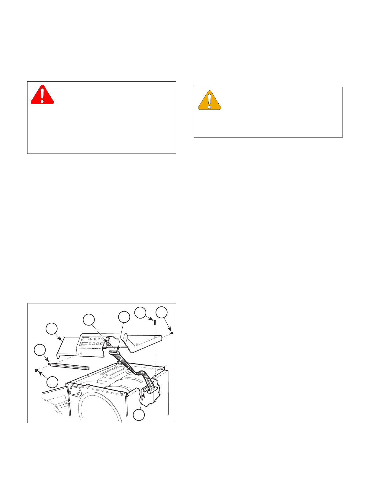
4.2 Top Cover Removal / Installation
A. Removal
(1) Disconnect power cord from the outlet.
(2) If the sterilizer contains a printer, remove printer
(Refer to Operation Manual).
(3) Open sterilizer door.
(4) Remove two screws (1, Figure 4-1) and steam
block (2) from top cover (3).
(5) Remove four screws (4) and two screws (5)
from top cover (3).
5
7A
4
6
3
2
(6) On units which apply, carefully break front of
top cover (3) loose from silicone sealant.
EQUIPMENT ALERT
Lift top cover carefully and slowly. Rib-
bon connector is still connected to display
PC board and any excess pressure exerted on it
could result in a damaged ribbon connector or
display PC board.
(7) Lift rear of top cover (3) and disconnect ribbon
connector (6) from display PC board (7A) or
control PC board (7B) (depending on whether
ribbon connector (6) is part of display PC board
or is a separate component).
(8) Remove top cover (3) from sterilizer.
B. Installation
(1) Coat mating surfaces of front panel lip and top
cover (3) with silicone sealant.
(2) Position top cover (3) over sterilizer, with rear of
top cover raised, and connect ribbon connector
(6) to display PC board (7A) or control PC
board (7B).
(3) Install top cover (3) on sterilizer and secure
using two screws (5) and four screws (4).
(4) Install steam block (2) on top cover (3) and
secure using two screws (1).
(5) Close sterilizer door.
(6) If the sterilizer contains a printer, install printer
(Refer to Operation Manual).
4.3 Right Hand Side Panel Removal /
Installation
1
Figure 4-1. Top Cover Removal / Installation
© Midmark Corporation 1998 SF-1572 Page 4-1 Printed in U.S.A.
7B
MA204802
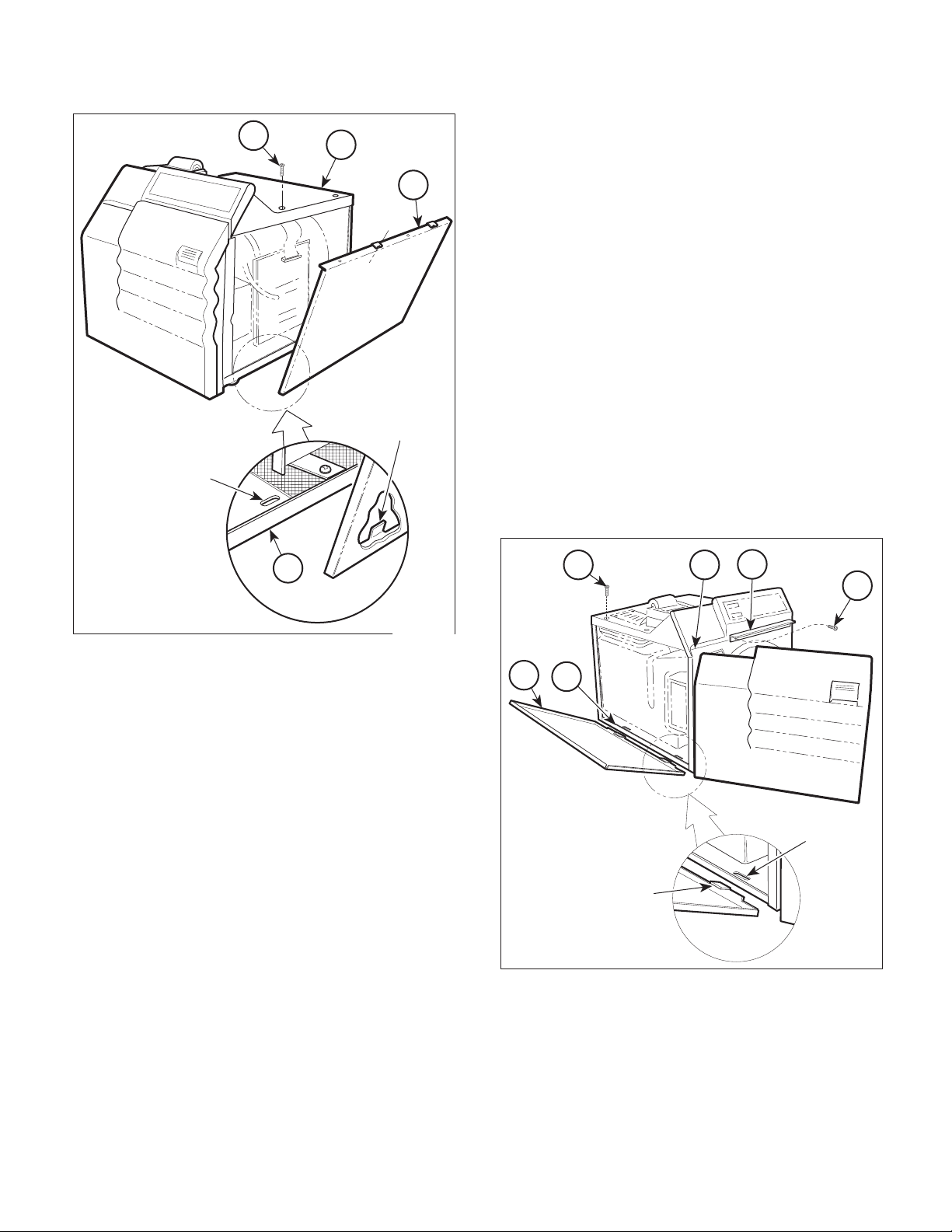
A. Removal
(1) Disconnect power cord from the outlet.
(2) Remove two screws (1, Figure 4-2) from top
cover (2).
Page 24
!"#$%&'(%3
Return To Table Of Contents
.+%'$"'+'#"(4(!"*3%#"
1
2
(3) Remove left screw (1, Figure 4-3) from steam
block (2).
SLOT
3
TAB
4
(4) Remove two screws (3) from top cover (4).
(5) Lift up the left hand corner of top cover (4), pull
outward and down on the top edge of the left
hand side panel (5), and remove left hand side
panel from sterilizer.
B. Installation
(1) Insert two tabs of left hand side panel (5) into
two slots of base (6).
(2) Lift up the left hand corner of top cover (4),
raise the top edge of left hand side panel (5)
into position, and secure using two screws (3).
(3) Install left screw (1) on steam block (2).
(4) Close sterilizer door.
3 4
2
1
MA2049-01
Figure 4-2. Right Hand Side Panel
Removal / Installation
(3) Pull outward and down on the top edge of the
right hand side panel (3) and remove right hand
side panel from sterilizer.
B. Installation
(1) Insert two tabs of right hand side panel (3) into
two slots of base (4).
(2) Raise top edge of right hand side panel (3) into
position and secure using two screws (1).
4.4 Left Hand Side Panel Removal / Installation
A. Removal
(1) Disconnect power cord from the outlet.
(2) Open sterilizer door.
5
6
SLOT
TAB
MA2050-01
Figure 4-3. Left Hand Side Panel
Removal / Installation
© Midmark Corporation 1998 SF-1572 Page 4-2 Printed in U.S.A.
Page 25
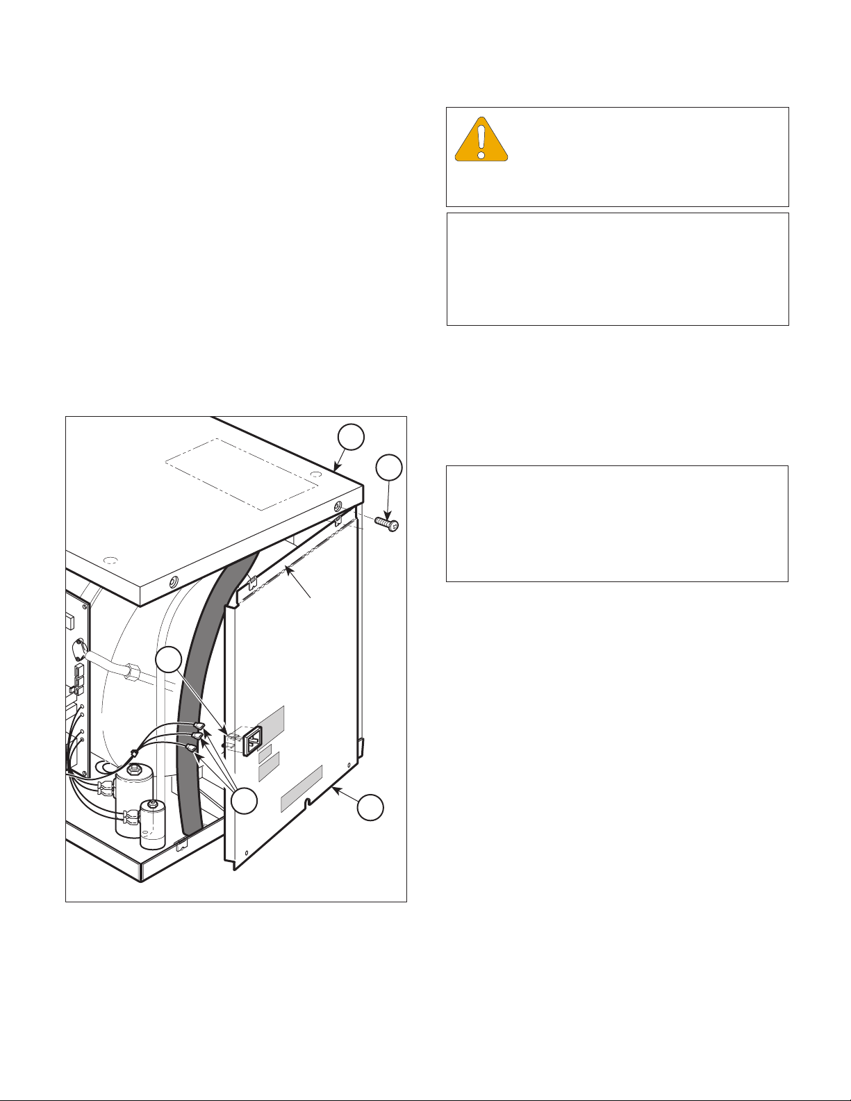
4.5 Back Panel Removal / Installation
Return To Table Of Contents
A. Removal
(1) Disconnect power cord from sterilizer.
(2) Remove right hand side panel (Refer to
para 4.3).
(3) Remove left hand side panel (Refer to
para 4.4).
(4) Remove four screws (1, Figure 4-4) from back
panel (2).
(5) Partially remove back panel (2) by simulta-
neously pulling downward and outward on back
panel.
!"#$%&'(%3
.+%'$"'+'#"(4(!"*3%#"
EQUIPMENT ALERT
Ensure that wires are completely discon-
nected before attempting to remove back
panel. Failure to do so could result in damage to
sterilizer.
NOTE
Units prior to serial number CZ1110/OM1000 have a
fuse holder attached to the back panel. On these
sterilizers, tag and disconnect two wires from the
receptacle and one wire from the fuse holder instead
of performing step 6.
(6) On older units, tag and disconnect three wires
(3) from terminals of receptacle (4) and remove
back panel (2) from sterilizer. On newer units,
separate back panel (2) from unit as far as
possible and lay it on its side.
5
B. Installation
1
NOTE
Units prior to serial number CZ1110/OM1000 have a
fuse holder attached to the back panel. On these
sterilizers, remove tags and connect two wires to the
receptacle and one wire to the fuse holder instead of
performing step 1.
FLAP
4
(1) On older units, remove tags and connect three
wires (3) to terminals of receptacle (4).
(2) Position flap of back panel (2) behind top cover
(5) and secure back panel in place using four
screws (1).
(3) Install left hand side panel (Refer to para 4.4).
(4) Install right hand side panel (Refer to para 4.3).
4.6 Base Inspection Cover Removal /
3
2
Installation
A. Removal
Figure 4-4. Back Panel Removal / Installation
© Midmark Corporation 1998 SF-1572 Page 4-3 Printed in U.S.A.
(1) Disconnect power cord from outlet.
MA2051-01
(2) Drain water from condensing tank.
(3) Turn sterilizer onto its back.
Page 26

!"#$%&'(%3
Return To Table Of Contents
.+%'$"'+'#"(4(!"*3%#"
(4) Remove two screws (1, Figure 4-5) and base
inspection cover (2) from base (3).
B. Installation
(1) Install base inspection cover (2) on base (3)
and secure using two screws (1).
(2) Turn sterilizer upright.
(3) Refill condensing tank with distilled water.
4.7 Bellows Assembly Removal /
Installation
A. Removal
(1) Remove back panel (Refer to para 4.5).
(2) Disconnect tube (1, Figure 4-6) from tee (2).
(3) Pull downward on bellows assembly (3) to
remove bellows assembly from condensing
tank (4).
(4) Loosen and remove tubes (1 and 5) from
bellows assembly (3).
4
TUBE
HOLE
5
3
1
2
1
2
3
Figure 4-5. Base Inspection Cover
Removal / Installation
MA2053-01
Figure 4-6. Bellows Assembly
Removal / Installation
B. Installation
(1) Connect tubes (1 and 5) to bellows assem-
bly (3).
(2) Position bellows assembly (3) and insert tube
(5) into tube hole of condensing tank (4).
(3) Connect tube (1) to tee (2).
(4) Install back panel (Refer to para 4.5).
MA2052-01
© Midmark Corporation 1998 SF-1572 Page 4-4 Printed in U.S.A.
Page 27

4.8 Condensing Tank Water Level Sensor
Return To Table Of Contents
Removal / Installation (Applies only to
Units with old style Control PC Board
with EPROM Version M or Before)
!"#$%&'(%3
.+%'$"'+'#"(4(!"*3%#"
NOTE
Units with old style control PC board with EPROM
version N or after or new style control PC board do
not have a condensing tank water level sensor.
A. Removal
(1) Drain water from condensing tank.
(2) Remove back panel (Refer to para 4.5).
(3) Remove bellows assembly (Refer to para 4.7).
(4) Disconnect wire (1, Figure 4-7) from termi-
nal (2).
(5) Using Water Level Sensor Wrench to hold
fitting (3), loosen nut (4) (Refer to Table 1-2 for
special tool).
(6) Pull assembled level sensor rod (5) from
fitting (3).
(7) Remove nut (4), silicone tube (6), and crimp (7)
from level sensor rod (5). Discard silicone tube
and crimp.
3
6
4
2
8
7
5
1
MA2054-01
Figure 4-7. Condensing Tank Water Level
Sensor Removal / Installation
(2) Install crimp (7), nut (4), and silicone tube (6)
on level sensor rod (5) and secure by crimping
crimp (7).
(3) Install assembled level sensor rod (5) in
fitting (3).
(8) Using vise grips to hold level sensor rod (5),
remove nut (8) and terminal (2) from level
sensor rod.
B. Installation
(1) Using vise grips to hold level sensor rod (5),
install terminal (2) on level sensor rod and
secure using nut (8).
(4) Using Water Level Sensor Wrench to hold
fitting (3), tighten nut (4) (Refer to Table 1-2 for
special tool).
(5) Connect wire (1) to terminal (2).
(6) Install bellows assembly (Refer to para 4.7).
EQUIPMENT ALERT
The end of the silicone tube must extend
past nut (4) after nut is installed. If it is
not, the level sensor rod will not function properly
because the terminal will be in contact with nut (4).
© Midmark Corporation 1998 SF-1572 Page 4-5 Printed in U.S.A.
Page 28

!"#$%&'(%3
Return To Table Of Contents
.+%'$"'+'#"(4(!"*3%#"
(7) Install back panel (Refer to para 4.5).
(8) Refill condensing tank with distilled water.
4.9 Temperature Sensor Assembly
Removal / Installation
A. Removal
(1) Remove back panel (Refer to para 4.5).
NOTE
Units with old style control PC board with EPROM
version N or after or new style control PC board will
only have two wire harnesses to disconnect instead
of three.
(2) Disconnect two / three wire harnesses (1,
Figure 4-8) from two / three terminals (2).
(3) Remove flex guard tubing (3) from two / three
wire harnesses (1).
(4) Remove temperature sensor assembly (4) from
pressure vessel (5).
B. Installation
(1) Coat threads of temperature sensor assembly
(4) with teflon tape.
(2) Install temperature sensor assembly (4) in
pressure vessel (5).
(3) Install flex guard tubing (3) on three wire
harnesses (1).
(4) Connect three wire harnesses (1) to three
terminals (2).
(5) Install back panel (Refer to para 4.5).
4.10 Pressure Vessel Water Level Sensor
Removal / Installation
A. Removal
(1) Remove back panel (Refer to para 4.5).
(2) Remove wire tray rack and tray plate (Refer to
para (4-17).
2
5
4
1
3
MA2074-01
Figure 4-8. Temperature Sensor Assembly
Removal / Installation
(3) Disconnect wire (1, Figure 4-9) from termi-
nal (2).
(4) Remove nut (3) and terminal (2) from level
sensor rod (4).
(5) Remove nut (5).
EQUIPMENT ALERT
Do not try to pull level sensor rod out of
back side of pressure vessel. Doing so
will damage level sensor rod.
(6) Push level sensor rod (4) thru fitting (6) and into
pressure vessel (7) and remove level sensor
rod.
(7) Remove spacer (8) from level sensor rod (4).
(8) Remove silicone tube (9) from fitting (6).
Discard silicone tube (9) and crimp (10).
(9) If damaged, remove fitting (6) from pressure
vessel (7).
© Midmark Corporation 1998 SF-1572 Page 4-6 Printed in U.S.A.
Page 29

!"#$%&'(%3
Return To Table Of Contents
.+%'$"'+'#"(4(!"*3%#"
(6) Install terminal (2) on level sensor rod (4) and
secure using nut (3).
7
8
4
6
9
10
5
1
Figure 4-9. Pressure Vessel Water Level
Sensor Removal / Installation
B. Installation
(1) If removed, coat fitting (6) with teflon tape and
install fitting in pressure vessel (7).
(2) Install silicone tube (9) and spacer (8) on level
sensor rod (4).
NOTE
The assembled level sensor rod must be installed
from the inside of the pressure vessel.
2
3
MA2055-01
(7) Connect wire (1) to terminal (2).
(8) Install wire tray rack and tray plate (Refer to
para 4.17).
(9) Install back panel (Refer to para 4.5).
4.11 Vent Solenoid Removal /
Installation
A. Removal
NOTE
Units prior to serial number CZ1110/OM1000 have a
manifold assembly which secures the vent solenoid.
Refer to the parts list to remove the vent solenoid on
these sterilizers.
(1) Drain water from condensing tank.
(2) Remove back panel (Refer to para 4.5).
(3) Tag and disconnect two wires (1, Figure 4-10)
from terminals (3).
(4) Tag and disconnect two wires (2) from termi-
nals (4).
(5) Disconnect three tubes (5 thru 7) from elbows
(8 thru 10).
(6) Remove two screws (11) from bottom of
manifold assembly (12).
(3) Install assembled level sensor rod (4) in
fitting (6).
EQUIPMENT ALERT
The end of the silicone tube must extend
past nut (5) after nut is installed. If it is
not, the level sensor rod will not function properly
because the terminal will be in contact with nut (5).
(4) Install and crimp crimp (10) on silicone
tube (9).
(5) Install nut (5).
© Midmark Corporation 1998 SF-1572 Page 4-7 Printed in U.S.A.
NOTE
Spacer (12A) is only on newer units.
(7) Remove manifold assembly (12) and spacer
(12A) from base (13).
(8) Hold screw (1, Figure 4-11) and loosen nut (2).
Turn terminals out of the way.
(9) Remove assembled vent solenoid (3) and
elbow (4) from tee (5).
Page 30

!"#$%&'(%3
Return To Table Of Contents
.+%'$"'+'#"(4(!"*3%#"
12
3
1
5
2
8
4
7
10
12A
(6) Hold screw (1) and tighten nut (2).
EQUIPMENT ALERT
When installing the vent solenoid, the
side of the solenoid marked IN needs to
be connected to the pressure line. Reversing vent
solenoid will cause system failure.
6
(7) Install spacer (12A, Figure 4-10) and manifold
9
assembly (12) on base (13) and secure using
two screws (11).
(8) Connect three tubes (5 thru 7) to elbows (8
thru 10).
(9) Connect two wires (2) to terminals (4).
(10) Connect two wires (1) to terminals (3).
13
11
MA2056-02
Figure 4-10. Vent Solenoid Removal / Installation
(10) Remove elbows (4 and 6) from vent sole-
noid (3).
B. Installation
NOTE
The end of elbow (6) which receives a tube does not
get coated with teflon tape.
(1) Coat the threads of elbows (4 and 6, Figure 4-
11) with teflon tape.
(2) Install elbows (4 and 6) on vent solenoid (3).
(3) Hold screw (1) and loosen nut (2). Turn
terminals out of the way.
(4) Install assembled elbow (4) and vent solenoid
(3) on tee (5).
(11) Install back panel (Refer to para 4.5).
(12) Refill condensing tank with distilled water.
1
2
TERMINALS
5
4
Figure 4-11. Vent Solenoid Fittings
Removal / Installation
6
3
MA205701
(5) Turn terminals of vent solenoid (3) so wires will
connect easily to vent solenoid.
© Midmark Corporation 1998 SF-1572 Page 4-8 Printed in U.S.A.
Page 31

!"#$%&'(%3
Return To Table Of Contents
.+%'$"'+'#"(4(!"*3%#"
4.12 Fill Solenoid Removal / Installation
A. Removal
NOTE
Units prior to serial number CZ1110/OM1000 have a
manifold assembly which secures the fill solenoid.
Refer to the parts list to remove the fill solenoid on
these sterilizers.
(1) Drain water from condensing tank.
(2) Remove back panel (Refer to para 4.5).
(3) Tag and disconnect two wires (1, Figure 4-12)
from terminals (3).
(4) Tag and disconnect two wires (2) from
terminals (4).
(5) Disconnect three tubes (5 thru 7) from elbows (8
thru 10).
(6) Remove two screws (11) from bottom of
manifold assembly (12).
NOTE
Spacer (12A) is only on newer units.
(7) Remove manifold assembly (12) and spacer
(12A) from base (13).
(8) Hold screw (1, Figure 4-13) and loosen nut (2).
Turn terminals out of the way.
(9) Remove assembled vent solenoid (3) and
elbow (4) from tee (5).
(10) Remove elbow (6) and tee (5) from fill
solenoid (7).
(11) Remove elbow (8) from fill solenoid (7).
B. Installation
(1) Coat threads of tee (5, Figure 4-13) and elbows
(6 and 8) with teflon tape.
(2) Install elbow (8) on fill solenoid (7).
(3) Install elbow (6) and tee (5) on fill solenoid (7).
(4) Loosen nut (9). Turn terminals of fill solenoid
(7) so wires will connect easily to fill solenoid.
Tighten nut (9).
(5) Coat threads of elbow (4) with teflon tape.
(6) Hold screw (1) and loosen nut (2). Turn
12
terminals out of the way.
3
1
7
7
9
8
10
1
6
5
9
TERMINALS
2
2
8
4
12A
13
6
5
4
3
MA205801
11
Figure 4-13. Fill Solenoid Fittings
MA2056-02
Removal / Installation
Figure 4-12. Fill Solenoid Removal / Installation
© Midmark Corporation 1998 SF-1572 Page 4-9 Printed in U.S.A.
Page 32

!"#$%&'(%3
Return To Table Of Contents
.+%'$"'+'#"(4(!"*3%#"
(7) Install assembled elbow (4) and vent solenoid
(3) on tee (5).
(8) Turn terminals of vent solenoid (3) so wires will
connect easily to vent solenoid.
(9) Hold screw (1) and tighten nut (2).
EQUIPMENT ALERT
When installing the vent solenoid and the
fill solenoid, the side of the solenoids
marked "IN" need to be connected to the pressure
lines. Reversing solenoids will cause system failure.
(10) Install spacer (12A, Figure 4-12) and manifold
assembly (12) on base (13) and secure using
two screws (11).
(11) Connect three tubes (5 thru 7) to elbows (8
thru 10).
(12) Connect two wires (2) to terminals (4).
(13) Connect two wires (1) to terminals (3).
(14) Install back panel (Refer to para 4.5).
(15) Refill condensing tank with distilled water.
4.13 Control PC Board Removal /
Installation
(5) Tag and disconnect two wires (7) from
terminals (8).
(6) Disconnect ribbon connector (9) from connec-
tor (10).
(7) Tag and disconnect neutral wire (11) from
terminal (12).
(8) Tag and disconnect hot wire (13) from termi-
nal (14).
(9) Disconnect printer cable (15) from connec-
tor (16).
(10) Disconnect door switch harness (17) from
connector (18).
(11) Tag and disconnect two wires (19) from pulse
solenoid terminals (20).
(12) Disconnect heater element wire (21) from
connector (22).
NOTE
Positions of locknuts (1) and screws (2) are reversed
on newer units.
(13) Remove two locknuts (1, Figure 4-15), screws
(2), and control PC board (3) and control PC
board bracket (4) as an assembly from
base (5).
A. Removal
(1) Remove right hand side panel (Refer to
para 4.3).
(2) Disconnect pressure tube (1, Figure 4-14) from
pressure sensor (2).
NOTE
Units with old style control PC board with EPROM
version N or after or new style control PC board will
only have two wire harnesses (3) to disconnect
instead of three.
(3) Disconnect two / three wire harnesses (3) from
two / three connectors (4).
(4) Tag and disconnect two wires (5) from termi-
nals (6).
NOTE
Units prior to serial number CZ1110/OM1000 have
the ground wire attached to the control PC board
bracket. When nut (6), starwasher (7), and screw (8)
are removed, ground wire will also be removed.
(14) Remove nut (6), starwasher (7), and screw (8)
from control PC board bracket (4).
(15) Turn three standoff screws (9) 1/4 turn in the
counter-clockwise direction and remove control
PC board (3) and insulator (10) from control PC
board bracket (4).
© Midmark Corporation 1998 SF-1572 Page 4-10 Printed in U.S.A.
Page 33

OLD STYLE
Return To Table Of Contents
PC BOARD
17
!"#$%&'(%3
.+%'$"'+'#"(4(!"*3%#"
10
18
20
21
17
19
15
9
2
1
16
3
4
14
12
11
5
7
2
1
8
6
NEW STYLE
PC BOARD
4
20
22
21
9
18
15
19
13
10
16
3
© Midmark Corporation 1998 SF-1572 Page 4-11 Printed in U.S.A.
13
22
12
14
11
5
7
8
6
Figure 4-14. Control PC Board Connections
MA207505
Page 34

!"#$%&'(%3
Return To Table Of Contents
.+%'$"'+'#"(4(!"*3%#"
9
(3) Install control PC board (3) and control PC
board bracket (4) as an assembly on base (5)
and secure using two screws (2) and locknuts (1).
10
4
2
6
7
3
8
5
1
Figure 4-15. Control PC Board Removal / Installation
B. Installation
(1) Install insulator (10, Figure 4-15) and control
PC board (3) on control PC board bracket (4)
and secure by turning three standoff screws (9)
1/4 turn in the clockwise direction.
MA2073-01
(4) Connect heater element wire (21, Figure 4-14) to
connector (22).
(5) Connect two wires (19) on pulse solenoid
terminals (20).
(6) Connect wire harness (17) to connector (18).
(7) Connect printer cable (15) to connector (16).
(8) Connect hot wire (13) to terminal (14).
(9) Connect neutral wire (11) to terminal (12).
(10) Connect ribbon connector (9) to connec-
tor (10).
(11) Connect two wires (7) to terminals (8).
(12) Connect two wires (5) to terminals (6).
NOTE
Units with old style control PC board with EPROM
version N or after or new style control PC board will
only have two wire harnesses (3) to connect instead
of three.
(13) Connect two / three wire harnesses (3) to two /
three connectors (4).
(14) Connect pressure tube (1) to pressure sen-
sor (2).
NOTE
Units prior to serial number CZ1110/OM1000 have
the ground wire attached to the control PC board
bracket. When nut (6), starwasher (7), and screw (8)
are removed, ground wire will also be removed.
Make sure ground wire is re-installed upon installation.
(2) Install screw (8), starwasher (7), and nut (6) on
control PC board bracket (4).
NOTE
Positions of locknuts (1) and screws (2) are reversed
on newer units.
© Midmark Corporation 1998 SF-1572 Page 4-12 Printed in U.S.A.
(15) Install right hand side panel (Refer to para 4.3).
Page 35

SECTION IV
Return To Table Of Contents
MAINTENANCE / SERVICE
4.14 Door Switch Removal / Installation
A. Removal
NOTE
Units prior to serial number CZ1110/OM1000 have a
different switch weldment. Since this procedure
tampers with the pressure vessel integrity, it should
not be attempted until a Midmark service representative has been contacted.
(1) Open sterilizer door.
(2) Remove right hand side panel (Refer to
para 4.3).
(3) Disconnect wire harness (1, Figure 4-16) from
connector (2).
(4) Using 3/32 in. punch, remove two roll pins (3)
from door switch bracket (4) (Refer to Table 1-2
for special tool).
(5) Remove door switch (5) from door switch
bracket (4).
B. Installation
(1) Position door switch (5) in door switch
bracket (4).
(2) Using 3/32 in. punch, install two roll pins (3) in
door switch bracket (4) (Refer to Table 1-2 for
special tool).
(3) Connect wire harness (1) to connector (2).
(4) Install right hand side panel (Refer to
para 4.3).
(5) Close sterilizer door.
4.15 Pulse Solenoid Removal / Installation
A. Removal
(1) Remove control PC board (Refer to para 4.13).
(2) Remove two screws (1, Figure 4-17) from pulse
solenoid (2).
(3) Remove nut (3) and shoulder screw (4), and
then remove pulse solenoid (2) and latch lever
(5) as an assembly from pressure vessel
bracket (6).
Figure 4-16. Door Switch Removal / Installation
(4) Using 3/32 in. punch, remove roll pin (7) and
latch lever (5) from plunger of pulse solenoid
(2) (Refer to Table 1-2 for special tool).
B. Installation
(1) Using 3/32 in. punch, install latch lever (5) on
plunger of pulse solenoid (2) and secure using
roll pin (7) (Refer to Table 1-2 for special tool).
(2) Coat shoulder screw (4) with Loctite 271.
(3) Install latch lever (5) and pulse solenoid (2) as
an assembly on pressure vessel bracket (6).
Secure using shoulder screw (4) and nut (3).
© Midmark Corporation 1998 SF-1572 Rev. 9/00 Page 4-13 Printed in U.S.A.
Page 36

!"#$%&'(%3
Return To Table Of Contents
.+%'$"'+'#"(4(!"*3%#"
4
5
PLUNGER
3
(4) Loosen two nuts (5) and pull top of bracket (6)
approximately 1 in. from pressure vessel (7).
(5) Rotate terminals (3 and 4) to a vertical position
and slide thermostat (8) upward and out of
bracket (6).
B. Installation
(1) Slide thermostat (8) into bracket (6) and rotate
terminals (3 and 4) to a horizontal position.
(2) Position bracket (6) against pressure vessel (7)
and secure by tightening two nuts (5).
7
1
2
6
Figure 4-17. Pulse Solenoid Removal / Installation
MA2060-01
NOTE
The holes for the two screws (1) are oblong. Install
screws at the top of each hole first, then adjust
downward as necessary if door will not open.
(4) Position pulse solenoid (2) on pressure vessel
bracket (6) and secure in position using two
screws (1).
(5) Install control PC board (Refer to para 4.13).
4.16 Thermostat Removal / Installation
A. Removal
(3) Connect wires (1 and 2) to terminals (3 and 4).
(4) Install base inspection cover (Refer to
para 4.6).
(5) Refill condensing tank with distilled water.
8
1
4
3
2
7
6
5
(1) Drain water from condensing tank.
(2) Remove base inspection cover (Refer to
para 4.6).
(3) Tag and disconnect wires (1 and 2, Figure 4-
18) from terminals (3 and 4).
© Midmark Corporation 1998 SF-1572 Page 4-14 Printed in U.S.A.
MA2062-01
Figure 4-18. Thermostat Removal / Installation
Page 37

!"#$%&'(%3
Return To Table Of Contents
.+%'$"'+'#"(4(!"*3%#"
4.17 Wire Tray Rack and Tray Plate
Removal / Installation
A. Removal
(1) Open sterilizer door.
(2) Remove trays.
(3) Pull wire tray rack (1, Figure 4-19) and tray
plate (2) from pressure vessel (3).
B. Installation
(1) Position two rear posts of wire tray rack (1) in
rack holes of tray plate (2).
(2) Hold front end of wire tray rack (1) at approxi-
mately a 30° angle from tray plate (2).
NOTE
If wire tray rack is not raised, installation is very
difficult.
(4) Install trays.
(5) Close sterilizer door.
4.18 Heating Element and Gasket
Removal / Installation
A. Removal
(1) Drain water from condensing tank.
(2) Remove base inspection cover (Refer to
para 4.6).
(3) Tag and disconnect two wires (1, Figure 4-20)
from terminals (2).
(4) Remove two nuts (3), lock washers (4), and
brass washers (5).
EQUIPMENT ALERT
Over bending may result in broken or
cracked terminals.
(3) Insert rear end of wire tray rack (1) and tray
plate (2) as an assembly in pressure vessel (3).
Push wire tray rack and tray plate as far as they
will go.
1
2
30°
HOLE
3
MA2047-01
NOTE
The following step is necessary to remove the
heating element from the pressure vessel.
(5) Straighten terminals (2) slightly from the
present 90° position to approximately a 10°
straighter position.
(6) Remove bracket (6) from pressure vessel (7)
and position out-of-way.
(7) Turn sterilizer upright.
(8) Remove wire tray rack and tray plate (Refer to
para 4.17).
(9) Remove heating element (8) and spacer assem-
bly (9) from pressure vessel (7).
NOTE
Perform the following step only if the heating element
is
not
being replaced, but damaged gaskets
(10) Remove two gaskets (10) from heating ele-
ment (8).
are
.
Figure 4-19. Wire Tray Rack and Tray Plate
Removal / Installation
© Midmark Corporation 1998 SF-1572 Page 4-15 Printed in U.S.A.
Page 38

!"#$%&'(%3
Return To Table Of Contents
.+%'$"'+'#"(4(!"*3%#"
7
9
2
EQUIPMENT ALERT
Hold heating element firmly in position
while tightening nuts. Otherwise, damage
to heating element or improper positioning of heating
element may result. Also, spacer assembly must
remain above gaskets. If spacer assembly is
installed under gasket, leaking will result.
6
4
3
5
1
Figure 4-20. Heating Element and Gasket
Removal / Installation
B. Installation
(1) Install two gaskets (10) on heating element (8).
EQUIPMENT ALERT
Over bending may result in broken or
cracked terminals.
8
10
MA2061-01
(6) Install two brass washers (5), lock washers (4),
and nuts (3) on heating element (8).
EQUIPMENT ALERT
Over bending may result in broken or
cracked terminals.
(7) Bend terminals (2) slightly, back to their original
90° position.
(8) Connect two wires (1) to terminals (2).
(9) Turn sterilizer upright.
(10) Install wire tray rack and tray plate (Refer to
para 4.17).
(11) Install base inspection cover (Refer to
para 4.6).
(12) Refill condensing tank with distilled water.
4.19 Filter Removal / Installation
NOTE
The following step is necessary to install the heating
element in the pressure vessel.
(2) Straighten terminals (2) slightly from the
present 90° position to approximately a 10°
straighter position.
(3) Install spacer assembly (9) and heating element
(8) in pressure vessel (7).
(4) Turn sterilizer on its back.
(5) Position bracket (6) on pressure vessel (7).
© Midmark Corporation 1998 SF-1572 Page 4-16 Printed in U.S.A.
A. Removal
(1) Remove wire tray rack and tray plate (Refer to
para 4.17).
NOTE
Turn filter in a circular motion while pulling upward to
remove.
(2) Using vise grips, remove filter (1, Figure 4-21)
from pressure vessel (2).
B. Installation
(1) Position filter (1) in pressure vessel (2).
Page 39

!"#$%&'(%3
Return To Table Of Contents
.+%'$"'+'#"(4(!"*3%#"
GROOVE
3
1
SLOT
2
MA2063-01
2
Figure 4-21. Filter Removal / Installation
(2) Using rubber hammer, tap filter (1) lightly into
pressure vessel (2).
(3) Install wire tray rack and tray plate (Refer to
para 4.17).
4.20 Door Gaskets Removal / Installation
A. Removal
(1) Open sterilizer door.
(2) Remove dam gasket (1, Figure 4-22) and door
gasket (2) from door (3).
B. Installation
(1) Install door gasket (2) in groove in door (3).
(2) Install dam gasket (1) by inserting bottom edge
of dam gasket in slot of door gasket (2) and
tucking top edge of dam gasket under flap of
door (3).
(3) Close sterilizer door.
FLAP
Figure 4-22. Door Gaskets Removal / Installation
1
MA2064-01
4.21 Display PC Board Removal /
Installation
A. Removal
(1) Remove top cover (Refer to para 4.2).
(2) Remove six screws (1, Figure 4-23) and
display PC board (2) from top cover (3).
(3) If damaged, remove gasket (4) from top
cover (3).
B. Installation
(1) If removed, install new gasket (4) by peeling
protective backing off of gasket and pressing
gasket firmly into position on top cover (3).
(2) Install display PC board (2) on top cover (3)
and secure using six screws (1).
© Midmark Corporation 1998 SF-1572 Page 4-17 Printed in U.S.A.
(3) Install top cover (Refer to para 4.2).
Page 40

!"#$%&'(%3
Return To Table Of Contents
.+%'$"'+'#"(4(!"*3%#"
3
1
2
4
Figure 4-23. Display PC Board
Removal / Installation
4.22 Condensing Tank Assembly
Removal / Installation
A. Removal
(1) Drain water from condensing tank.
MA2065-01
2
1
MA2066-01
Figure 4-24. Condensing Tank Assembly Fill Tube
Disconnection / Connection
(8) Loosen hose clamp (1, Figure 4-25) and
remove sight/drain tube (2) and hose clamp
from condensing tank assembly (3).
NOTE
The following step applies only to units with old style
control PC board with EPROM version M or before.
Units with old style control PC board with EPROM
version N or after or new style control PC board do
not have wire (4) and terminal (5).
(9) Disconnect wire (4) from terminal (5).
(2) Turn sterilizer onto its back.
(3) Disconnect fill tube (1, Figure 4-24) from
elbow (2).
(4) Turn sterilizer upright.
(5) Remove top cover (Refer to para 4.2).
(6) Remove back panel (Refer to para 4.5).
(7) Remove bellows assembly (Refer to para 4.7).
© Midmark Corporation 1998 SF-1572 Page 4-18 Printed in U.S.A.
(10) Disconnect vent tube (6) from fitting (7).
NOTE
Positions of locknut (9) and screws (8) are reversed
on newer units.
(11) Remove screw (8), locknut (9), and condensing
tank assembly (3) from base (10).
B. Installation
NOTE
Fill tube must be lined up with fitting at this time
because it will be impossible to line up after screw
and locknut are installed.
Page 41

!"#$%&'(%3
Return To Table Of Contents
.+%'$"'+'#"(4(!"*3%#"
(1) Position condensing tank assembly (3, Figure
4-25) on base (10) and secure using screw (8)
and locknut (9).
(2) Connect vent tube (6) to fitting (7).
NOTE
The following step applies only to units with old style
control PC board with EPROM version M or before.
Units with old style control PC board with EPROM
version N or after or new style control PC board do
not have wire (4) and terminal (5).
(3) Connect wire (4) to terminal (5).
(4) Install hose clamp (1) and sight/drain tube (2)
on condensing tank assembly (3). Tighten
hose clamp.
(5) Install bellows assembly (Refer to para 4.7).
(6) Install back panel (Refer to para 4.5).
(7) Install top cover (Refer to para 4.2).
(8) Turn sterilizer onto its side.
(11) Refill condensing tank with distilled water.
4.23 Pressure Relief Valve Removal /
Installation
A. Removal
(1) Remove condensing tank assembly (Refer to
para 4.22).
(2) Disconnect tube (1, Figure 4-26) from
elbow (2).
(3) Remove elbow (2) from pressure relief
valve (3).
(4) Remove pressure relief valve (3) from pressure
vessel (4).
B. Installation
(1) Coat threads of pressure relief valve (3) and
elbow (2) with teflon tape.
(2) Install pressure relief valve (3) in pressure
vessel (4).
(9) Connect fill tube (1, Figure 4-24) to elbow (2).
(10) Turn sterilizer upright.
6
7
5
4
10
Figure 4-25. Condensing Tank Assembly
Removal / Installation
8
2
3
9
MA2067-01
3
2
4
1
MA2068-01
1
Figure 4-26. Pressure Relief Valve
Removal / Installation
© Midmark Corporation 1998 SF-1572 Page 4-19 Printed in U.S.A.
Page 42

!"#$%&'(%3
Return To Table Of Contents
.+%'$"'+'#"(4(!"*3%#"
(3) Install elbow (2) on pressure relief valve (3).
(4) Connect tube (1) to elbow (2).
(5) Install condensing tank assembly (Refer to
para 4.22).
4.24 Pressure / Temperature Potentiometers Adjustments
EQUIPMENT ALERT
The pressure zero, pressure range, and
temperature potentiometers cannot be
adjusted separately. If one potentiometer needs
adjusted, then the entire potentiometer adjustment
procedure must be performed, and it must be
performed in the proper sequence as follows:
DANGER
The following steps require the steril-
izer to be plugged in to power while
the adjustment is being performed. Do not touch
any components except for the adjusting screw
of the potentiometer. Failure to comply with
these instructions could result in an electrical
shock, which could result in severe personal
injury or death.
NOTE
After the following step is performed, the display PC
board lamps will individually illuminate and then
extinguish one at a time in a left to right sequence.
When all the lamps have illuminated and extinguished, proceed with step 4.
(1) Remove right hand side panel.
(2) Open sterilizer door.
TEMP / TIME DISPLAY
TEMP (°F) \ TIME (MIN : SECONDS)
FILLING
PRESSURE (PSI)
PRESSURE
DISPLAY
UNWRAPPED
BUTTON
UNWRAPPED
POUCHES
BUTTON
STERILIZING
POUCHES
LIQUIDS
BUTTON
LAMP
DRYING
LIQUIDS
PACKS
BUTTON
(3) Press and hold down the LIQUIDS and PACKS
buttons simultaneously while connecting the
power cord to the sterilizer (See Figure 4-27).
Release the LIQUIDS and PACKS buttons.
LAMP
COMPLETE
PACKS
WATER LOW
START
START
BUTTON
DOOR AJAR
STOP
STOP
BUTTON
ERROR
ON/STANDBY
ON / STANDBY
BUTTON
MA207701
Figure 4-27. Display PC Board Lamp / Display / Button Check
© Midmark Corporation 1998 SF-1572 Page 4-20 Printed in U.S.A.
Page 43

NOTE
Return To Table Of Contents
When each button is pressed, its corresponding lamp
will illuminate and stay illuminated. Also, after the
following step, the PRESSURE (PSI) display will
display the pressure that the control PC board is
reading and the TEMP (°F) / TIME (MIN: SECONDS)
display will display the temperature that the control
PC board is reading. When each button has been
pushed, proceed with step 5.
!"#$%&'(%3
.+%'$"'+'#"(4(!"*3%#"
counter-clockwise direction to raise the voltage
setting until the multimeter reading is 2.550
VDC ±0.001 VDC.
(9) Close the sterilizer door.
(10) Connect Pressure Gauge Test Harness to
sterilizer (See Figure 4-29) (Refer to the
sterilizer Service and Parts Manual for this
special tool).
(4) Press and release the UNWRAPPED,
POUCHES, LIQUIDS, PACKS, START, STOP,
AND ON/STANDBY buttons one at a time and
in this order.
(5) Turn adjusting screw of pressure zero potenti-
ometer (1, Figure 4-28) in the counter-clockwise direction until the PRESSURE (PSI)
display reads 0.0 psi (0.0 kPa).
(6) Turn adjusting screw of pressure zero potenti-
ometer (1) in the clockwise direction until the
PRESSURE (PSI) display reads 0.1 psi (1
kPa).
CAUTION
The multimeter leads must be connected
exactly as shown in the illustration.
Connecting a lead to the wrong side of the resistor or
wrong pin of the chip will result in an incorrect
adjustment.
(7) Set the multimeter to read VDC at least the 5
Volts range. Connect the red lead of a multimeter to Test Point (A) and the black lead of a
multimeter to Test Point (B).
(11) Press the START button to start a test/calibra-
tion cycle and wait until the temperature on the
TEMP (°F) / TIME (MIN: SECONDS) display
reaches 272 - 273°F (133-134°C) (See Figure
4-27).
NOTE
Turning the adjusting screw of the pressure range
potentiometer in the clockwise direction raises the
sterilizer pressure reading while turning the adjusting
screw in the counter-clockwise direction lowers the
sterilizer pressure reading.
(12) Turn the adjusting screw of the pressure range
potentiometer (2, Figure 4-28) in the clockwise
or counter-clockwise direction until the reading
on the PRESSURE (PSI) display matches the
reading of the Pressure Gauge Test Harness
within a tolerance of ±0.5 psi (3.5 kPa).
(13) Recheck the multimeter reading. It should still
read 2.550 VDC ±0.001 VDC.
(14) Press the STOP button to end the test/calibra-
tion cycle and allow the sterilizer to vent and
open its door (See Figure 4-27).
NOTE
In the following step, if the digital multimeter being
used has only three digits, adjust to a reading of 2.54
VDC and then adjust and set to where the reading
just changes to 2.55 VDC.
(8) The multimeter should read 2.550 VDC ±0.001
VDC. If multimeter reading is not 2.550 VDC
±0.001 VDC, adjust the adjusting screw of the
temperature potentiometer (3) in a clockwise
direction to lower the voltage setting or a
© Midmark Corporation 1998 SF-1572 Page 4-21 Printed in U.S.A.
(15) Disconnect the leads of the multimeter from
Test Points (A and B, Figure 4-28).
(16) Disconnect the power cord from the sterilizer
and then repeat steps 3 and 4 of this procedure. The reading should read 0.1 psi (1 kPa)
with the sterilizer door open. If not, repeat
steps 5 and 6 of this procedure.
Page 44

!"#$%&'(%3
O
F
F
1
2
3
4
R32
U12
Return To Table Of Contents
.+%'$"'+'#"(4(!"*3%#"
NEW STYLE
PC BOARD
ADJUSTING
SCREWS
A
3
B
2
A
B
1
3
1
3
ADJUSTING
SCREWS
ADJUSTING
SCREW
© Midmark Corporation 1998 SF-1572 Page 4-22 Printed in U.S.A.
Figure 4-28. Potentiometer Adjustments
OLD STYLE
PC BOARD
2
MA407700
Page 45

!"#$%&'(%3
Return To Table Of Contents
.+%'$"'+'#"(4(!"*3%#"
4.25 Display PC Board Lamp / Display /
2
Button Check
TUBE
FITTING
PRESSURE GAUGE
TEST HARNESS
To connect Pressure Gauge Test Harness to sterilizer:
1. Disconnect tube (1) from pressure sensor (2).
2. Connect tube of Pressure Guage Test Harness
to pressure sensor (2).
3. Connect tube (1) to fitting of Pressure Guage
Test Harness.
To disconnect Pressure Gauge Test Harness from
sterilizer:
1. Disconnect tube (1) from fitting of Pressure
Guage Test Harness.
2. Disconnect tube of Pressure Guage Test Harness
from pressure sensor (2).
3. Connect tube (1) to pressure sensor (2).
1
MA2070-01
Figure 4-29. Connecting / Disconnecting Pressure
Gauge Test Harness
(17) Disconnect the power cord from sterilizer.
(1) Disconnect power cord from the sterilizer.
(2) Press and hold down the LIQUIDS and PACKS
buttons simultaneously, while connecting the
power cord to the sterilizer (See Figure 4-30).
Release the LIQUIDS and PACKS buttons.
(3) Observe the display PC board lamps. In a left
to right sequence, each lamp on the display PC
board should individually illuminate and then
extinguish. If all the display PC board lamps do
not illuminate and then extinguish, replace
display PC board (Refer to para 4.21).
(4) Press and release the UNWRAPPED,
POUCHES, LIQUIDS, PACKS, START, STOP,
AND ON/STANDBY buttons one at a time and
in this order.
(5) Observe the lamps that correspond with each
button. If all lamps do not illuminate and stay
illuminated when their corresponding button is
pressed, replace the display PC board (Refer to
para 4.21).
(6) Observe the pressure and temperature/time
displays. If the pressure and temperature/time
displays do not display pressure and temperature readings, replace the display PC board
(Refer to para 4.21).
(7) Disconnect power cord from the sterilizer.
(18) Disconnect Pressure Gauge Test Harness from
sterilizer (See Figure 4-29).
(19) Install right hand side panel.
© Midmark Corporation 1998 SF-1572 Page 4-23 Printed in U.S.A.
Page 46

!"#$%&'(%3
Return To Table Of Contents
.+%'$"'+'#"(4(!"*3%#"
TEMP / TIME DISPLAY
TEMP (°F) \ TIME (MIN : SECONDS)
FILLING
STERILIZING
LAMP
DRYING
COMPLETE
WATER LOW
DOOR AJAR
LAMP
ERROR
PRESSURE (PSI)
UNWRAPPED
POUCHES
PRESSURE
DISPLAY
UNWRAPPED
BUTTON
POUCHES
BUTTON
LIQUIDS
BUTTON
Figure 4-30. Display PC Board Lamp / Display / Button Check
4.26 Pressure Relief Valve Check
(1) Remove the top inspection cover (1,
Figure 4-31).
WARNING
Refer to the operator manual for
complete instructions on operating the
sterilizer. Failure to do so could result in severe
personal injury.
(2) Select the UNWRAPPED cycle and start the
cycle.
DANGER
Pressure Relief Valve will be hot.
Use a screwdriver or rod to pull the
wire ring. Do not pull the wire ring with bare
hands or burns will result. Steam will be vented
from under the rear of the sterilizer. To keep
from being burned, place a steam barrier (a
rolled up towel) around the bottom of the sterilizer.
LIQUIDS
PACKS
BUTTON
PACKS
START
STOP
ON/STANDBY
ON / STANDBY
BUTTON
START
BUTTON
STOP
BUTTON
MA207701
(3) When the “heat up” portion of the cycle is
complete and the elapsed time is being counted
down on the display PC board, pull on wire ring
of pressure relief valve (2) with a screwdriver.
(4) If excessive force was required to open pres-
sure relief valve (2), replace the pressure relief
valve (Refer to para 4.23).
NOTE
If the pressure relief valve does not close completely
when the wire ring is released, pull the wire ring
again and release it quickly so the valve snaps back
into position. Do this until the valve seats properly.
(5) Release wire ring of pressure relief valve (2).
The steam should vent out of the pressure
relief valve until the wire ring is released. When
the wire ring is released, the valve should seat,
stopping the release of steam.
(6) If the pressure relief valve (2) will not re-seat
properly, replace the pressure relief valve
(Refer to para 4.23).
© Midmark Corporation 1998 SF-1572 Page 4-24 Printed in U.S.A.
(7) Install top inspection cover (1).
Page 47
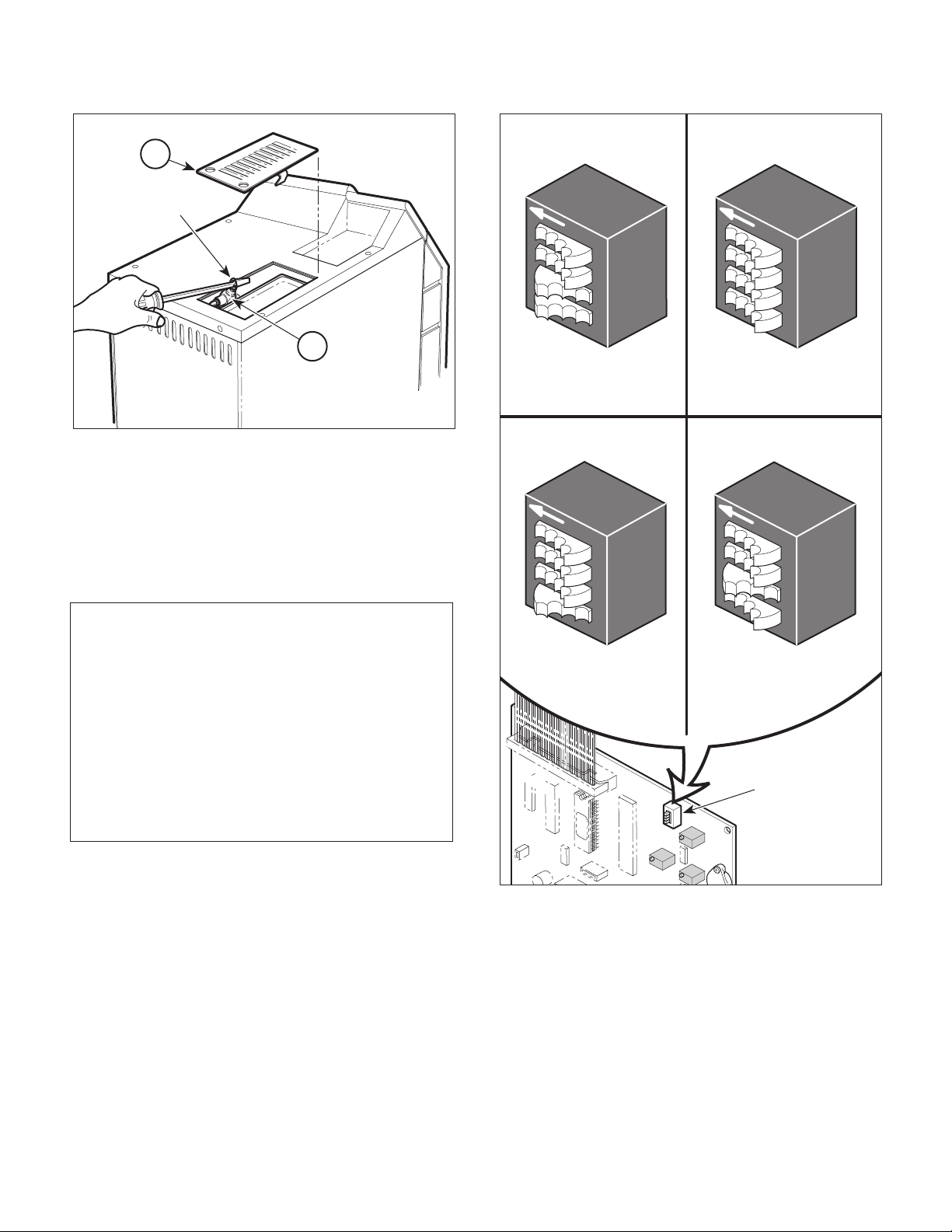
!"#$%&'(%3
Return To Table Of Contents
.+%'$"'+'#"(4(!"*3%#"
1
WIRE
RING
2
MA2072-01
Figure 4-31. Pressure Relief Valve Check
4.27 Dry Cycle Dip Switches Adjustment
(1) Unplug power cord from outlet receptacle.
(2) Remove right hand side panel (Refer to
para 4.3).
NOTE
There are four repeat interval dip switch settings;
setting #1, setting #2, setting #3, and setting #4. The
unit comes factory set at the repeat interval setting #3. Setting #1 is shortest repeat interval, setting
#2 is longer, setting #3 is longer yet, and setting #4 is
the longest repeat interval.
SETTING #1
REPEAT INTERVAL
F
F
O
1
2
3
4
#3 SWITCH DEPRESSED
TO RIGHT (ON)
#4 SWITCH DEPRESSED
TO RIGHT (ON)
SETTING #2
REPEAT INTERVAL
F
F
O
1
2
3
4
#3 SWITCH DEPRESSED
TO LEFT (OFF)
#4 SWITCH DEPRESSED
TO RIGHT (ON)
SETTING #3
REPEAT INTERVAL
F
F
O
1
2
3
4
#3 SWITCH DEPRESSED
TO LEFT (OFF)
#4 SWITCH DEPRESSED
TO LEFT (OFF)
SETTING #4
REPEAT INTERVAL
F
F
O
1
2
3
4
#3 SWITCH DEPRESSED
TO RIGHT (ON)
#4 SWITCH DEPRESSED
TO LEFT (OFF)
This procedure only applies to units with a new style
control PC board; units with serial numbers: CZ2457, DA-1005, DB-1150, DX-1970, DY-1139, FD1000, and OM-9449 thru Present.
(3) If unit has has been overheating during the
drying cycle and activating the overheat
thermostat, determine the current repeat
interval dip switch settings for the unit per
Figure 4-32 and then change the dip switch
settings to the next shortest repeat interval.
(4) Run a cycle. Repeat step 3 if overheat thermo-
stat activates again.
(5) Install right hand side panel (Refer to para 4.3).
© Midmark Corporation 1998 SF-1572 Page 4-25 Printed in U.S.A.
DRY CYCLE
DIP SWITCH
MA374000
Figure 4-32. Dry Cycle Dip Switches Adjustment
Page 48

!"#$%&'(%3
Return To Table Of Contents
.+%'$"'+'#"(4(!"*3%#"
© Midmark Corporation 1998 SF-1572 Page 4-26 Printed in U.S.A.
Page 49

SECTION V
Return To Table Of Contents
SCHEMATICS AND DIAGRAMS
5.1 Wiring Diagram
Figure 5-1, sheets 1 thru 3, illustrates the wiring connections for the sterilizer.
Printer
Printer
Connector
12345
Blue
N.O.
Black
Door Switch
Door Pulse
Solenoid
100V Unit 7.90 ohms
120V Unit 14.0 ohms
240V Unit 52.0 ohms
PCB/Heater
(015-0657-00)
Heating Element
100V Unit 6.81 to 7.52 ohms
120V Unit 9.77 to 10.80 ohms
240V Unit 40.46 to 44.71 ohms
PCB/Printer
Harness
(015-0668-00)
Orange (Ground)
Green (Ground)
Red (Power)
Blue (Busy)
White (Data)
Black
Black
Yellow
Green
Harness
Harness (015-0877-00)
4
5
2
PCB/AC/Thermostat
3
1
Display Panel
PC Board
Hot Neutral
Control
PC Panel
Overheat
thermostat
White
Ribbon Cable
Connector
(015-0646-00)
Flex Guard
Tubing
(015-0257-02)
Ground
Green/Yellow or
Green
Green
(015-0679-00)
Black
SECTION V
SCHEMATICS AND DIAGRAMS
Temperature
Probe Assembly
Level
Sensor Assembly
Red
Black (+5 V.)
White (Ground)
Red (V. Out)
Black
Black
Fill Solenoid
100V Unit 137 ohms
120V Unit 140 ohms
240V Unit 818 ohms
L
G
U
A.C. Connector
Receptacle
Black
Chamber Level
Sensor Harness
(015-0654-00)
Green
Reservoir
Sensor Assembly
Black
Red
Red
Red
Vent Solenoid
100V Unit 375 ohms
120V Unit 400 ohms
240V Unit 1960 ohms
Reservoir
Sensor
Harness
(015-0655-00)
Cordset
U.S.A. 015-0640-00
Cont. Europe 015-0688-07
Italian 015-0688-08
Swiss 015-0688-09
United Kingdom 015-0688-10
Australian 015-0688-11
Israeli 015-0688-12
Japanese 015-0363-06
MA246706
Figure 5-1 (Sheet 1 of 3). Wiring Diagram (Applies To Serial Numbers CZ1000 thru CZ1684, DB1000 thru DB1010,
OM1000 thru OM5130, DX1000 thru DX1170, DA1000 thru DA1001, and DY1000 thru DY1007
© Midmark Corporation 1998 SF-1572 Rev. 7/01 Page 5-1 Printed in U.S.A.
Page 50

SECTION V
Return To Table Of Contents
SCHEMATICS AND DIAGRAMS
Printer
Connector
12345
N.O.
Door Switch
PCB/Printer
Harness
Orange (Ground)
Green (Ground)
Red (Power)
Blue (Busy)
White (Data)
Blue
Black
4
3
5
2
1
Display Panel
PC Board
Printer
Control
PC Panel
Ribbon Cable
Connector
Flex Guard
Tubing
Probe Assembly
Black (+5 V.)
White (Ground)
Red (V. Out)
Temperature
Red
Black
Level
Sensor Assembly
Chamber Level
Sensor Harness
Door Pulse
Solenoid
100V Unit 7.90 ohms
120V Unit 14.0 ohms
240V Unit 52.0 ohms
Black
Black
Yellow
Green
PCB/Heater
Harness
Hot Neutral
Overheat
thermostat
Ground
Black
Black
Fill Solenoid
100V Unit 137 ohms
120V Unit 140 ohms
240V Unit 818 ohms
Red
Red
Vent Solenoid
100V Unit 375 ohms
120V Unit 400 ohms
240V Unit 1960 ohms
Cordset
U.S.A. 015-0640-00
Cont. Europe 015-0688-07
Italian 015-0688-08
Swiss 015-0688-09
United Kingdom 015-0688-10
Australian 015-0688-11
Israeli 015-0688-12
Japanese 015-0363-06
MA246707
Heating Element
100V Unit 6.81 to 7.52 ohms
120V Unit 9.77 to 10.80 ohms
240V Unit 40.46 to 44.71 ohms
PCB/AC/Thermostat
Harness (015-0877-00)
White
Green/Yellow
Black
L
G
N
A.C. Connector
Receptacle
Figure 5-1 (Sheet 2 of 3) Wiring Diagram (Applies To Serial Numbers CZ1685 thru CZ4590, DB1011 thru DB1149,
OM5131 thru OM14723, DX1171 thru DX1969, DA1002 thru DA1004, and DY1008 thru DY1138)
© Midmark Corporation 1998 SF-1572 Rev. 7/01 Page 5-2 Printed in U.S.A.
Page 51

Printer
Return To Table Of Contents
Connector
12345
PCB/Printer
Harness
Orange (Ground)
Green (Ground)
Red (Power)
Blue (Busy)
White (Data)
SECTION V
SCHEMATICS AND DIAGRAMS
Printer
4
3
5
2
1
Display Panel
PC Board
Temperature
Probe Assembly
Ribbon Cable
Connector
Level
Sensor Assembly
Red
Black
Chamber Level
Sensor Harness
Control
PC Panel
Flex Guard
Tubing
Black (+5 V.)
Red (V. Out)
White (Ground)
Door Switch
PCB/Heater
Harness
Heating Element
100V Unit 6.81 to 7.52 ohms
120V Unit 9.77 to 10.80 ohms
240V Unit 40.46 to 44.71 ohms
Blue
N.O.
Black
Door Pulse
Solenoid
100V Unit 7.90 ohms
120V Unit 14.0 ohms
240V Unit 52.0 ohms
Green
Yellow
120 V. CORDSET
(U.S.A.)
015-1139-00
Black
Black
Overheat
thermostat
Green/Yellow
Black
White
015-1138-00
Hot
Neutral
PCB/AC/Thermostat
Ground
Harness
Black
Black
Fill Solenoid
100V Unit 137 ohms
120V Unit 140 ohms
240V Unit 818 ohms
Overheat
thermostat
Black
Green/Yellow
White
Red
Red
Cont. Europe 015-0688-07
Italian 015-0688-08
Swiss 015-0688-09
United Kingdom 015-0688-10
Australian 015-0688-11
Israeli 015-0688-12
Japanese 015-0363-06
L
G
N
A.C. Connector
Receptacle
Vent Solenoid
100V Unit 375 ohms
120V Unit 400 ohms
240V Unit 1960 ohms
230 V.
Cordset
MA376202
Figure 5-1 (Sheet 3 of 3) Wiring Diagram (Applies To Serial Numbers CZ4591 thru Present,
DA1005 thru Present, DB1150 thru Present, DX1970 thru Present, DY1139 thru Present,
© Midmark Corporation 1998 SF-1572 Rev. 7/01 Page 5-3 Printed in U.S.A.
FD1000 thru Present, and OM14724 thru Present)
Page 52

SECTION V
Return To Table Of Contents
SCHEMATICS AND DIAGRAMS
5.2 Flow Diagram
Figure 5-2 illustrates the water, heated water, steam,
and vented steam/water flow throughout the sterilizer
during a cycle.
Condensing
Tank / Reservoir
Pressure
Vessel
PHASE 1 (Filling) PHASE 2 (Heat-Up)
Bellows
Vent
Solenoid
Fill
Solenoid
Water
Control
PC
Board
Water
Heated
Water
Steam/Air
PHASE 3 (Sterilizing) PHASE 4 (Vent)
Water
Steam
Water
Steam
© Midmark Corporation 1998 SF-1572 Rev 7/01 Page 5-4 Printed in U.S.A.
Heated
Water
Figure 5-2. Flow Diagram
Heated
Water
Vented
Steam/Water
MA207902
Page 53

5.3 Pressure / Temperature Chart
Return To Table Of Contents
Table 5-1 is a chart which lists what pressure should be
present at particular temperature.
Table 5-1. Pressure / Temperature Chart
SECTION V
SCHEMATICS AND DIAGRAMS
PSI °C °F
0100.0212.0
1101.9215.4
2103.6218.5
3105.3221.5
4106.9224.4
5108.4227.1
6109.8229.6
711.3232.3
8112.6234.7
9113.9237.0
10 115.2 239.4
11 116.4 241.5
12 117.6 243.7
13 118.8 245.8
14 119.9 247.8
15 121.0 249.8
Normal steam sterilizing range is 250 °F to 270 °F.
PSI °C °F
16 122.0 251.6
17 123.0 253.4
18 124.1 255.4
19 125.0 257.0
20 126.0 258.8
21 126.9 260.0
22 127.8 262.0
23 128.7 263.7
24 129.6 265.3
25 130.4 266.7
26 131.3 268.3
27 132.1 269.8
28 132.9 271.2
29 133.7 272.7
30 134.5 274.1
Figures in chart are for steam pressure only. The
presence of any air in the autoclave invalidates
temperature readings.
© Midmark Corporation 1998 SF-1572 Page 5-5 Printed in U.S.A.
Page 54

SECTION V
Return To Table Of Contents
SCHEMATICS AND DIAGRAMS
© Midmark Corporation 1998 SF-1572 Page 5-6 Printed in U.S.A.
Page 55

SECTION VI
Return To Table Of Contents
PARTS LIST
6.1 Introduction
The illustrated parts list provides information for identifying and ordering the parts necessary to maintain the
sterilizer in peak operating condition. Refer to paragraph
1.5 for parts ordering information.
The parts list also illustrates disassembly and assembly
relationships of parts.
6.2 Description of Columns
The
Item
column of the parts list gives a component its
own unique number. The same number is given to the
component in the parts illustration. This allows a part
number of a component to be found if the technician can
visually spot the part on the illustration. The technician
simply finds the component in question on the illustration and notes the item number of that component.
Then, he finds that item number in the parts list. The
row corresponding to the item number gives the technician the part number, a description of the component,
and quantity of parts per subassembly. Also, if a part
number is known, the location of that component can be
determined by looking for the item number of the
component on the illustration.
The
Part No.
that component.
column lists the MIDMARK part number for
SECTION VI
PARTS LIST
The
Description
of the component.
The
Qty.
component that is required for the subassembly. The
letters “AR” denote “as required” when quantities of a
particular component cannot be determined, such as:
adhesive.
Bullets [ • ] in the
column show the indenture level of a component. If a
component does not have a bullet, it is a main component of that illustration. If a component has a bullet, it is
a subcomponent of the next component listed higher in
the parts list than itself that does not have a bullet.
Likewise, if a component has two bullets, it is a subcomponent of the next component listed higher in the parts
list than itself that has only one bullet.
column provides a physical description
column lists the number of units of a particular
Part No.
column and the
Description
6.3 Torque Specifications and Important
Assembly Notes
When specific assembly torque specifications, measurements, or procedures have been identified, by our
engineering department, as required to assure proper
function of the unit, those torque specifications, measurements, and procedures will be noted on the parts
illustrations. Adherence to these requirements is
essential.
Page 6-1© Midmark Corporation 1998 SF-1572 Printed in U.S.A.
Page 56

Pictorial Index
Return To Table Of Contents
2
SECTION VI
PARTS LIST
9
7
3
1
5
1
2
3
6
2
5
4
1
M9-001 Ritter M9 Ultraclave (115 VAC
[Serial Number Prefix "OM"]) ............... 6-2
M9-002 Ritter M9 Ultraclave (230VAC
[Serial Number Prefix "DY"]) ................ 6-2
M9-003 Midmark M9 Ultraclave (115 VAC
[Serial Number Prefix "CZ"]) ................ 6-2
M9-004 Midmark M9 Ultraclave (230 VAC
[Serial Number Prefix "DX"]) ................ 6-2
M9-005 Ritter M9 Ultraclave (100 VAC
[Serial Number Prefix "DB"]) ................ 6-2
M9-006 Ritter M9 Ultraclave (100VAC
[Serial Number Prefix "DA"]) ................ 6-2
M9-007 EMS M9 Ultraclave (230 VAC
[Serial Number Prefix "FD"]) ................ 6-2
M9-008 Dabi Atlante M9 Ultraclave (115 VAC
[Serial Number Prefix "FK"]) ................ 6-2
© Midmark Corporation 1998 SF-1572 Rev. 5/99 Page 6-2 Printed in U.S.A.
MA448700
Item Model No. Description PageItem Model No. Description Page
M9-009 Dabi Atlante M9 Ultraclave (230 VAC
[Serial Number Prefix "FL"]) ................. 6-2
M9-010 Polish M9 Ultraclave (230 VAC
[Serial Number Prefix "LA"]) ................. 6-2
1Main Enclosure Components.............. 6-3
2Plumbing & Sensor Components........ 6-4
3Pressure Vessel Components............ 6-5
4Manifold Components......................... 6-6
5Electrical Components........................ 6-7
6Control PC Board............................... 6-8
7Labels and Decals.............................. 6-9
8Printer Components (Not Shown)..... 6-10
9 Racks, Trays and Cleaner ............... 6-11
10 Packaging ........................................ 6-12
Always Specify Model & Serial Number
Page 57

Main Enclosure Components
Return To Table Of Contents
SECTION VI
PARTS LIST
14
20
8
1
4
14
3
2
5
4
6
9
8
10
7
11
11
8
19
8
14
8
13
12
15
21
16
15
18
8
14
7
17
14
24
22
22
23
Used on units with Serial Number: CZ1000 thru CZ1456 and OM1000 thru OM3287
Item Part No. Description Qty.Item Part No. Description Qty.
1030-0765-10 Top Inspection Cover ............................ 1
2050-1775-10 Cover Plate - Printer .............................. 1
3040-0008-37 Screw................................................... 2
4040-0010-88 Screw................................................... 4
5002-0356-00 Top Cover ............................................. 1
6050-2034-00 Top Cover Steam Block ........................ 1
7050-1767-10 Side Panel............................................. 2
8H352623 Tinnerman Clip .................................... 12
9040-0010-95 Screw................................................... 2
10 050-1777-00 Control PCB Bracket ............................. 1
11 040-00 10 -75 Screw ................................................... 5
12 016-0428-01 Screen .................................................. 1
Always Specify Model & Serial Number
13 050-2346-00 Bas e ..................................................... 1
14 040-00 10 -18 Screw ................................................. 11
15 041-0010-04 Nut - w/Starwasher ............................... 3
16 053-0394-00 Grommet (Early Units Only) .................. 1
17 050-4326-01 Base Inspection Cover .......................... 1
18 016-0404-00 Leveler Foot .......................................... 4
19 050-1778-00 Bracket ................................................. 1
20 050-1766-10 Back Panel ............................................ 1
21 041-0312-05 Lock Nut ............................................... 4
22 053-0388-01 Hose Clip .............................................. 2
23 042-0010-21 Pop Rivet .............................................. 2
24 053-00 68-11 Strain Relief Bushing ............................. 1
MA225400
© Midmark Corporation 1998 SF-1572 Rev. 5/99 Printed in U.S.A.
Page 6-3
Page 58

Main Enclosure Components
Return To Table Of Contents
SECTION VI
PARTS LIST
14
20
8
1
4
14
3
2
5
4
6
9
8
10
7
11
26
11
8
19
8
14
8
13
15
12
25
16
15
15
22
18
21
18
21
8
9
23
7
17
14
MA294400
22
24
Used on units with Serial Number: CZ1457 thru CZ2753, DA1000 thru DA1004, DB1000 thru DB1149,
DX1000 thru DX2131, DY1000 thru DY1149, FD1000 thru FD1099 and OM3288 thru OM10596
Item Part No. Description Qty.Item Part No. Description Qty.
1030-0765-10 Top Inspection Cover ............................ 1
2050-1775-10 Cover Plate - Printer .............................. 1
3040-0008-50 Screw................................................... 2
4040-0010-88 Screw................................................... 4
5002-0356-00 Top Cover (Domestic - English) ............ 1
002-0356-01 Top Cover (Metric - English) ................. 1
6050-2034-00 Top Cover Steam Block ........................ 1
7050-1767-10 Side Panel............................................. 2
8H352623 Tinnerman Clip .................................... 13
9040-0010-95 Screw................................................... 6
10 050-1777-00 Control PCB Bracket ............................. 1
11 040-00 10 -75 Screw ................................................... 3
12 016-0428-01 Screen .................................................. 1
13 050-2518-00 Bas e ..................................................... 1
Always Specify Model & Serial Number
14 040-00 10 -18 Screw ................................................... 7
15 041-0010-04 Nut - w/Starwasher ............................... 3
16 053-0394-00 Grommet (Early Units Only) .................. 1
17 050-4326-01 Base Inspection Cover .......................... 1
18 016-0523-00 Leveler Foot .......................................... 4
19 050-1778-00 Bracket ................................................. 1
20 050-1766-10 Back Panel ............................................ 1
21 040-00 10 -43 Screw ................................................... 4
22 053-0388-01 Hose Clip .............................................. 2
23 042-0010-21 Pop Rivet .............................................. 2
24 053-00 68-11 Strain Relief Bushing ............................. 1
25 045-0001-00 Washer ................................................. 4
26 040-00 10 -74 Screw ................................................... 2
© Midmark Corporation 1998 SF-1572 Rev. 5/99 Printed in U.S.A.
Page 6-3.1
Page 59
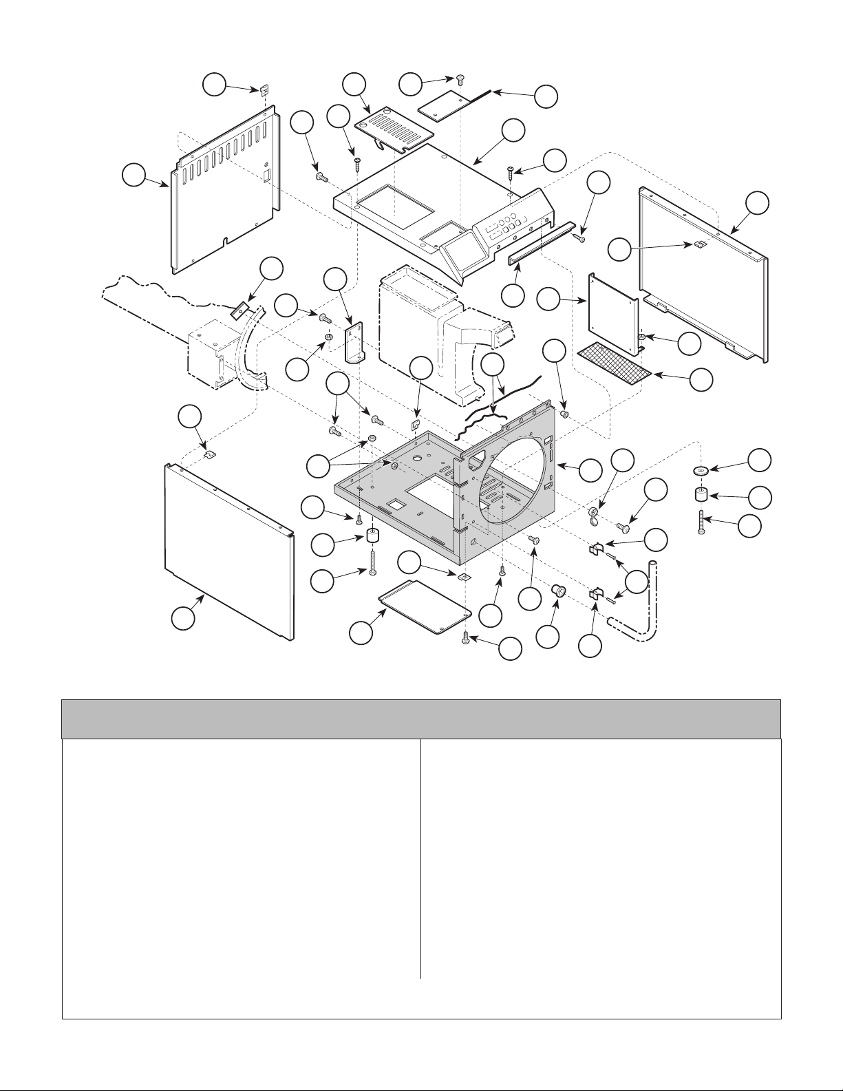
Main Enclosure Components
Return To Table Of Contents
SECTION VI
PARTS LIST
20
8
1
3
2
4
14
5
4
29
7
8
16
11
15
19
14
6
10
8
28
30
31
12
8
25
18
11
15
13
27
26
21
18
22
8
21
23
9
7
17
11
14
24
22
Used on units with Serial Number: CZ2753 thru CZ4530, DX2131 thru DX2588, DY1149 thru DY1178,
FD1099 thru FD1499, FK1000 thru FK1749,FL1000 thru FL1474 and OM10596 thru OM14666
1030-1117-00 Top Inspection Cover ............................ 1
2050-1775-00 Cover Plate - Printer .............................. 1
3040-0008-50 Screw................................................... 2
4040-0010-88 Screw................................................... 4
5002-0356-00 Top Cover (Domestic - English) ............ 1
002-0356-01 Top Cover (Metric - English) ................. 1
002-0356-02 Top Cover (Metric - French) ................. 1
6050-2034-00 Top Cover Steam Block ........................ 1
7050-1767-00 Side Panel............................................. 2
8H352623 Tinnerman Clip .................................... 10
9040-0010-95 Screw................................................... 4
10 050-3996-00 Control PCB Bracket ............................. 1
11 040-00 10 -75 Screw ................................................... 3
12 016-0428-04 Screen .................................................. 1
13 050-3605-00 Bas e ..................................................... 1
14 040-0010-125 Screw ................................................... 7
15 041-0010-02 Nut ....................................................... 6
© Midmark Corporation 1998 SF-1572 Rev. 3/00 Printed in U.S.A.
MA2944012
Item Part No. Description Qty.Item Part No. Description Qty.
16 050-4750-00 Flange Clamp ........................................ 2
17 050-4326-01 Base Inspection Cover .......................... 1
18 016-0523-01 Leveler Foot .......................................... 4
19 050-1778-00 Bracket ................................................. 1
20 050-3524-00 Back Panel ............................................ 1
21 040-00 10 -44 Screw ................................................... 4
22 053-0388-01 Hose Clip .............................................. 2
23 042-0010-21 Pop Rivet .............................................. 2
24 053-00 68-11 Strain Relief Bushing ............................. 1
25 045-0001-00 Washer ................................................. 4
26 040-0010-124 Screw ................................................... 2
27 053-0723-00 Screw Cover ......................................... 2
28 042-0021-00 Adhesive ............................................ AR
29 040-0010-113 Screw ................................................... 2
30 042-00 45 -01 Nutsert .................................................. 2
31 041-0010-04 Nut ....................................................... 2
Always Specify Model & Serial Number
Page 6-3.2
Page 60

Main Enclosure Components
Return To Table Of Contents
SECTION VI
PARTS LIST
20
8
1
3
2
4
14
5
4
29
7
8
16
11
15
19
14
6
10
8
28
30
31
12
8
25
18
11
15
13
27
26
21
18
22
8
21
23
9
7
17
11
14
24
22
Used on units with Serial Number CZ4531 thru CZ4590 and OM14666 thru OM14723
Item Part No. Description Qty.
1030-1117-00 Top Inspection Cover ............................ 1
2050-1775-00 Cover Plate - Printer .............................. 1
3040-0008-50 Screw................................................... 2
4040-0010-88 Screw................................................... 4
5002-0356-00 Top Cover (Domestic - English) ............ 1
002-0356-01 Top Cover (Metric - English) .................. 1
6050-2034-00 Top Cover Steam Block ........................ 1
7050-1767-00 Side Panel............................................. 2
8H352623 Tinnerman Clip .................................... 10
9040-0010-95 Screw................................................... 4
10 050-3996-00 Control PCB Bracket ............................. 1
11 040-00 10 -75 Screw ................................................... 3
12 016-0428-04 Screen .................................................. 1
13 050-3605-00 Bas e ..................................................... 1
14 040-0010-125 Screw ................................................... 7
15 041-0010-02 Nut ....................................................... 6
© Midmark Corporation 1998 SF-1572 Rev. 3/00 Printed in U.S.A.
MA294402
Item Part No. Description Qty.
16 050-4750-00 Flange Clamp ........................................ 2
17 050-4326-01 Base Inspection Cover .......................... 1
18 016-0523-01 Leveler Foot .......................................... 4
19 050-1778-00 Bracket ................................................. 1
20 050-3831-00 Back Panel ............................................ 1
21 040-00 10 -44 Screw ................................................... 4
22 053-0388-01 Hose Clip .............................................. 2
23 042-0010-21 Pop Rivet .............................................. 2
24 053-00 68-11 Stra in Relie f Bushing ............................. 1
25 045-0001-00 Washer ................................................. 4
26 040-0010-124 Screw ................................................... 2
27 053-0723-00 Screw Cover ......................................... 2
28 042-0021-00 Adhesive ............................................ AR
29 040-0010-113 Screw ................................................... 2
30 042-00 45 -01 Nutsert .................................................. 2
31 041-0010-04 Nut ....................................................... 2
Always Specify Model & Serial Number
Page 6-3.3
Page 61

Main Enclosure
Return To Table Of Contents
Components
8
14
20
16
11
19
SECTION VI
PARTS LIST
1
4
3
2
5
4
28
7
8
6
10
15
8
14
8
15
11
18
8
21
7
17
Used on units with Serial Number CZ4591, DA1005, DB1238, DX2589, DY1179,
FD1500, FK1750, FL1475, LA1000 and OM14724 thru Present
Item Part No. Description Qty.
1030-1117-00 Top Inspection Cover ............................ 1
2050-1775-00 Cover Plate - Printer .............................. 1
3040-0008-50 Screw................................................... 2
4040-0010-88 Screw................................................... 4
5002-0356-00 Top Cover (Domestic - English) ............ 1
002-0356-01 Top Cover (Metric - English) ................. 1
002-0356-02 Top Cover (Metric - French) ................. 1
6050-2034-00 Top Cover Steam Block ........................ 1
7050-1767-00 Side Panel............................................. 2
8H352623 Tinnerman Clip .................................... 10
9040-0010-95 Screw................................................... 5
10 050-3996-00 Control PCB Bracket ............................. 1
11 040-00 10 -75 Screw ................................................... 3
12 016-0428-04 Screen .................................................. 1
13 050-4325-00 Bas e ..................................................... 1
14 040-0010-125 Screw ................................................... 6
15 041-0010-02 Nut ....................................................... 5
Always Specify Model & Serial Number
29
30
27
12
26
13
25
18
21
22
23
9
11
24
14
Item Part No. Description Qty.
16 050-4750-00 Flange Clamp ........................................ 2
17 050-4326-00 Base Inspection Cover .......................... 1
18 016-0523-01 Leveler Foot .......................................... 4
19 050-1778-00 Bracket ................................................. 1
20 050-3831-00 Back Panel (230 V. ) ............................. 1
050-3831-01 Back Panel (120 V. ) ............................. 1
21 040-00 10 -44 Screw ................................................... 4
22 053-0388-01 Hose Clip .............................................. 2
23 042-0010-21 Pop Rivet .............................................. 2
24 053-00 68-11 Strain Relief Bushing ............................. 1
25 040-0010-124 Screw ................................................... 2
26 053-0723-00 Screw Cover ......................................... 2
27 042-0021-00 Adhesive ............................................ AR
28 040-0010-113 Screw ................................................... 2
29 042-00 45 -16 Nutsert .................................................. 2
30 041-0010-04 Nut ....................................................... 2
22
MA294404
© Midmark Corporation 1998 SF-1572 Rev. 3/00 Printed in U.S.A.
Page 6-3.4
Page 62

Plumbing & Sensor
Return To Table Of Contents
Components
15
10
9
4
8
3
6
2
SECTION VI
PARTS LIST
21
18
22
34
23
25
24
27
26
20
19
19
16
7
17
19
10
28
29
26
5
1
A
9
8
C
35
32
12
13
11
14
B
36
37
33
Used on units with Serial Number CZ1000 thru CZ1119 and OM1000 thru OM1352
Item Part No. Description Qty.Item Part No. Description Qty.
1053-0376-00 Condensing Tank .................................. 1
2053-0392-00 O-ring ................................................... 2
3014-0216-00 Bulkhead Union..................................... 1
4014-0205-00 Tube..................................................... 1
5014-0215-00 Union Drilled (Includes Sleeve) .............. 1
6045-0001-56 Lockwasher .......................................... 1
7057-0273-01 Lever Sensor Rod ................................. 1
8002-0358-00 Lever Sensor Tube (Includes
Item 9,10,16,30,and 31)) ....................... 2
9015-0595-00 Terminal................................................ 2
10 041-0006-02 Locknut ................................................. 2
11 053-0393-00 O-ring ................................................... 1
12 014-0209-00 Bulkhead Couple ................................... 1
13 014-0184-01 Male Elbow ............................................ 1
14 014-0203-00 Tub e ..................................................... 1
15 053-0376-01 Condensing Tank Lid ............................ 1
16 014-0212-0 0 Co nn ector ............................................. 1
17 014-0206-00 Tub e ..................................................... 1
18 002- 0375-00 Bello ws Ass embly ................................. 1
19 014-0392-00 Compression Nut .................................. 2
20 014-0208-00 Tub e ..................................................... 1
Always Specify Model & Serial Number
21 053-0394-00 Grommet ............................................... 1
22 014-0202-00 Male Branch Tee ................................... 1
23 014-0207-00 PCB Pressure Sensor Tube .................. 1
24 002-0359-00 Pressure Relief Valve (35 P.S.I.)
(I nclud es elb ow, It em 36) .... ..... ..... ..... . 1
25 053-0403-01 Tube - Pressure Relief .......................... 1
26 015-0013-05 Cable Tie (High Temp) .......................... 4
27 014-0217-00 Compression Connector ....................... 1
28 053-0404-01 Tube - PCB/Comp. Connector ............... 1
29 002-0357-00 Temperature Probe Assembly ............... 1
30 053-0407-00 Bushing ................................................. 1
31 030-0858-00 Level Sensor Assembly ......................... 1
32 014-0204-00 Tube ..................................................... 1
33 014-01 84-01 Male 90° Elbow ...................................... 1
34 014-0218-00 Male Elbow ............................................ 1
35 052-0173-0 0 Condensing Coil .................................... 1
36 016-0450-00 Hose Clip .............................................. 1
37 053-0391-01 Hose ..................................................... 1
(*) 002-0593-01 (*)Pressure Sensor Tube Kit (Includes #'s
19, 23, 26, 27, & 28)
30
31
MA201910
Page 6-4© Midmark Corporation 1998 SF-1572 Rev. 7/01 Printed in U.S.A.
Page 63

Plumbing & Sensor
Return To Table Of Contents
Components
15
10
9
4
8
3
6
2
SECTION VI
PARTS LIST
21
18
22
34
23
25
24
27
26
20
19
19
16
7
17
19
10
28
29
26
5
1
A
9
8
30
C
35
32
12
13
11
14
B
36
37
33
Used on Units with Serial Numbers: CZ1120 thru CZ1684, DA1000 thru
DA1001, DB1000 thru DB1010, DX1000 thru DX1000 and OM1353 thru OM4864
Item Part No. Description Qty.Item Part No. Description Qty.
1053-0512-00 Condensing Tank .................................. 1
2H98137 Gasket .................................................. 2
3014-0216-00 Bulkhead Union..................................... 1
4014-0205-00 Tube..................................................... 1
5014-0215-00 Union Drilled (Includes Sleeve) .............. 1
6045-0001-56 Lockwasher .......................................... 1
7057-0273-01 Lever Sensor Rod ................................. 1
8002-0358-00 Lever Sensor Tube (Includes
Item 9,10,16,30,and 31) ......................... 2
9015-0595-00 Terminal................................................ 2
10 041-0006-02 Locknut ................................................. 2
11 053-0393-00 O-ring ................................................... 1
12 014-0209-00 Bulkhead Couple ................................... 1
13 014-0184-01 Male Elbow ............................................ 1
14 014-0203-00 Tub e ..................................................... 1
15 053-0512-01 Condensing Tank Lid ............................ 1
16 014-0212-0 0 Co nn ector ............................................. 1
17 014-0206-00 Tub e ..................................................... 1
18 002- 0375-00 Bello ws Ass embly ................................. 1
19 014-0392-00 Compression Nut (Refer to Kit [*]) ......... 2
20 014-0208-00 Tub e ..................................................... 1
Always Specify Model & Serial Number
21 053-0394-00 Grommet ............................................... 1
22 014-0202-00 Male Branch Tee ................................... 1
23 014-0207-00 PCB Pres. Sensor Tube (Refer to Kit [*]) 1
24 002-0359-00 Pressure Relief Valve (35 P.S.I.)
(Includes Elbow, Item 36) .................. 1
25 053-0403-01 Tube - Pressure Relief .......................... 1
26 015-0013-05 Cable Tie (High Temp) .......................... 4
27 014-0217-00 Compression Connector (Refer to Kit [*]) 1
28 053-0404-01 Tube-PCB Connector (Refer to Kit [*]) ... 1
29 002-0357-00 Temperature Probe Assembly ............... 1
30 053-0407-00 Bushing ................................................. 1
31 030-0858-00 Level Sensor Assembly ......................... 1
32 014-0204-00 Tube ..................................................... 1
33 014-01 84 -01 Male 90° E l b o w ...................................... 1
34 014-0218-00 Male Elbow ............................................ 1
35 052-0173-0 0 Co nd ensing Coil .................................... 1
36 016-0450-00 Hose Clip .............................................. 1
37 053-0391-01 Hose ..................................................... 1
(*) 002-0593-01 (*)Pressure Sensor Tube Kit (Includes #'s
19, 23, 26, 27, & 28)
31
MA201910
© Midmark Corporation 1998 SF-1572 Rev. 7/01 Printed in U.S.A.
Page 6-4.1
Page 64

Plumbing & Sensor
Return To Table Of Contents
Components
15
10
4
8
3
6
2
SECTION VI
PARTS LIST
21
18
34
25
24
27
26
20
19
9
19
16
7
17
23
22
19
10
28
29
26
5
1
A
35
11
B
36
12
13
14
Used on Units with Serial Numbers: OM4865 thru OM5130
DX1001 thru DX1170 DY1000 thru DY1007
1053-0512-00 Condensing Tank .................................. 1
2H98137 Gasket .................................................. 2
3014-0216-00 Bulkhead Union..................................... 1
4014-0205-00 Tube..................................................... 1
5014-0215-00 Union Drilled (Includes Sleeve) .............. 1
6045-0001-56 Lockwasher .......................................... 1
7057-0273-01 Lever Sensor Rod ................................. 1
8002-0358-00 Lever Sensor Tube (Includes
9015-0595-00 Terminal................................................ 2
10 041-0006-02 Locknut ................................................. 2
11 053-0393-00 O-ring ................................................... 1
12 014-0209-00 Bulkhead Couple ................................... 1
13 014-0184-01 Male Elbow ............................................ 1
14 014-0203-00 Tub e ..................................................... 1
15 053-0512-01 Condensing Tank Lid ............................ 1
16 014-0212-0 0 Co nn ector ............................................. 1
17 014-0206-00 Tub e ..................................................... 1
18 002- 0375-00 Bello ws Ass embly ................................. 1
19 014-0392-00 Compression Nut (Refer to Kit [*]) ......... 2
20 014-0208-00 Tub e ..................................................... 1
Item 9,10,16,31,and 31) ......................... 2
Always Specify Model & Serial Number
9
8
30
C
32
33
37
Item Part No. Description Qty.Item Part No. Description Qty.
21 053-0394-00 Grommet ............................................... 1
22 014-0202-00 Male Branch Tee ................................... 1
23 014-0207-00 PCB Pres. Sensor Tube (Refer to Kit [*]) 1
24 002-0359-00 Pressure Relief Valve (35 P.S.I.)
25 053-0613-02 Tube - Pressure Relief .......................... 1
26 015-0013-05 Cable Tie (High Temp) .......................... 4
27 014-0217-00 Compression Connector (Refer to Kit [*]) 1
28 053-0404-01 Tube-PCB Connector (Refer to Kit [*]) ... 1
29 002-0357-00 Temperature Probe Assembly ............... 1
30 053-0407-00 Bushing ................................................. 1
31 030-0858-00 Level Sensor Assembly ......................... 1
32 014-0204-00 Tube ..................................................... 1
33 014-01 84 -01 Male 90° E l b o w ...................................... 1
34 014-0258-00 Male Elbow ............................................ 1
35 052-0173-0 0 Condensing Coil .................................... 1
36 016-0450-00 Hose Clip .............................................. 1
37 053-0391-01 Hose ..................................................... 1
(*) 002-0593-01 (*)Pressure Sensor Tube Kit (Includes #'s
(In cludes Elbow, Item 36 ) ... ...... ...... .. .. 1
19, 23, 26, 27, & 28)
31
MA201910
© Midmark Corporation 1998 SF-1572 Rev. 7/01 Printed in U.S.A.
Page 6-4.2
Page 65

Plumbing & Sensor
Return To Table Of Contents
Components
15
10
9
4
8
3
6
2
SECTION VI
PARTS LIST
21
18
22
34
23
25
24
27
26
20
19
19
16
7
17
19
10
28
29
26
35
5
1
A
9
8
30
C
31
32
12
13
11
14
B
36
37
33
Used on Units with Serial Numbers: CZ1685 thru CZ4334, DA1002 thru DA1004
DB1011 thru DB1237, DX1171 thru DX2555, DY1008 thru DY1176, FD1000 thru
FD1399, FK1000 thru FK1699, FL1000 thru FL1474 and OM5131 thru OM14524
Item Part No. Description Qty.Item Part No. Description Qty.
1053-0614-00 Condensing Tank .................................. 1
2H98137 Gasket .................................................. 1
3014-0216-00 Bulkhead Union..................................... 1
4014-0205-00 Tube..................................................... 1
5016-0450-00 Hose Clip .............................................. 1
6052-0173-00 Condensing Coil..................................... 1
7053-0391-01 Hose..................................................... 1
8002-0358-00 Lever Sensor Tube (Includes Item
9,10,16,30 and 31) ................................ 1
9015-0595-00 Terminal................................................ 1
10 041-00 06-02 Locknut ................................................. 1
11 053-0393-00 O-ring ................................................... 1
12 014-0209-00 Bulkhead Couple ................................... 1
13 014-0184-01 Male Elbow ............................................ 1
14 014-0203-00 Tub e ..................................................... 1
15 053-0614-01 Condensing Tank Lid ............................ 1
16 014-0212-0 0 Co nn ector ............................................. 1
17 014-0206-00 Tub e ..................................................... 1
18 002- 0375-00 Bello ws Ass embly ................................. 1
Always Specify Model & Serial Number
19 014-0392-00 Compression Nut (Refer to Kit [*]) ......... 2
20 014-0208-00 Tube ..................................................... 1
21 053-0394-00 Grommet ............................................... 1
22 014-0202-00 Male Branch Tee ................................... 1
23 014-0207-00 PCB Pres. Sensor Tube (Refer to Kit [*]) 1
24 002-0359-00 Pressure Relief Valve (35 P.S.I.)
(include Elbow, Item 35) ........................ 1
25 053-0613-01 Tube - Pressure Relief .......................... 1
26 015-0013-05 Cable Tie (High Temp) .......................... 4
27 014-0217-00 Compression Connector (Refer to Kit [*]) 1
28 053-0404-01 Tube-PCB Connector (Refer to Kit [*]) ... 1
29 002-0357-00 Temperature Probe Assembly ............... 1
30 053-0407-00 Bushing ................................................. 1
31 030-0858-00 Le vel Sensor Assembly......................... 1
32 014-0204-00 Tube ..................................................... 1
33 014-01 84 -01 Male 90° E l b o w ...................................... 1
34 014-0258-00 Male Elbow ............................................ 1
(*) 002-0593-01 (*)Pressure Sensor Tube Kit (Includes #'s
19, 23, 26, 27, & 28)
MA201911
Page 6-4.3© Midmark Corporation 1998 SF-1572 Rev. 7/01 Printed in U.S.A.
Page 66

Plumbing & Sensor
Return To Table Of Contents
Components
SECTION VI
PARTS LIST
26
28
28
29
26
15
18
22
25
21
27
24
23
20
19
10
19
16
9
8
17
4
3
2
1
6
A
30
31
32
12
13
11
14
B
5
7
33
Used on Units with Serial Numbers: CZ4335 thru CZ5944, DB1238 thru DB1262, DX2556 thru
DX2883,DY1177 thru DY1178, FD1400 thru FD1954, FK1700 thru FK2279, FL1475 thru FL1843 and
OM14525 thru OM17468
Item Part No. Description Qty.Item Part No. Description Qty.
1053-0614-00 Condensing Tank .................................. 1
2H98137 Gasket .................................................. 1
3014-0216-00 Bulkhead Union..................................... 1
4014-0205-00 Tube..................................................... 1
5016-0748-00 Hose Clip .............................................. 1
6052-0173-00 Condensing Coil..................................... 1
7053-0391-01 Hose..................................................... 1
8002-0358-00 Lever Sensor Tube (Includes Item
9,10,16,30,and 31) ................................ 1
9015-0595-00 Terminal................................................ 1
10 041-00 06-02 Locknut ................................................. 1
11 053-0393-00 O-ring ................................................... 1
12 014-0209-00 Bulkhead Couple ................................... 1
13 014-0184-01 Male Elbow ............................................ 1
14 014-0203-00 Tub e ..................................................... 1
15 053-0614-01 Condensing Tank Lid ............................ 1
16 014-0212-0 0 Co nn ector ............................................. 1
17 014-0206-00 Tub e ..................................................... 1
18 002- 0375-00 Bello ws Ass embly ................................. 1
Always Specify Model & Serial Number
19 014-0392-00 Compression Nut (Refer to Kit [*]) ......... 2
20 014-0208-00 Tub e ..................................................... 1
21 014-0258-00 Male Elbow ............................................ 1
22 014-0202-00 Ma le Branch Tee ................................... 1
23 014-0207-00 PCB Pres. Sensor Tube (Refer to Kit [*]) 1
24 002-0359-01 Pressure Relief Valve (40 P.S.I.)
(Includes Elbow, Item 35) ...................... 1
25 053-0613-01 Tube - Pressure Relief .......................... 1
26 015-0013-05 Cable Tie (High Temp) .......................... 4
27 014-0217-00 Compression Connector (Refer to Kit [*]) 1
28 053-0404-01 Tube-PCB Connector (Refer to Kit [*]) ... 1
29 002-0357-00 Temperature Probe Assembly ............... 1
30 053-0407-00 Bushing ................................................. 1
31 030-0858-00 Level Sensor Assembly ......................... 1
32 014-0204-00 Tub e ..................................................... 1
33 014-01 84 -01 Male 90° E l b o w ...................................... 1
(*) 002-0593-01 (*)Pressure Sensor Tube Kit (Includes #'s
19, 23, 26, 27, & 28)
MA201912
Page 6-4.4© Midmark Corporation 1998 SF-1572 Rev. 7/01 Printed in U.S.A.
Page 67

Plumbing & Sensor
Return To Table Of Contents
Components
SECTION VI
PARTS LIST
18
22
21
25
24
23
29
27
26
28
26
15
20
19
10
19
16
9
8
17
4
3
2
1
6
A
C
30
31
32
12
13
11
14
B
5
7
33
MA510809
Used on Units with Serial Numbers: CZ5945 thru CZ6530, DB1261 thru DB1272, DX2883 thru
DX2878,DY1178 thru DY1179, FD1954 thru FD1954, FK2279 thru FK2304, FL1843 thru FL1948, LA1000
thru LA1023 and OM17468 thru OM18880
Item Part No. Description Qty.Item Part No. Description Qty.
1053-0614-00 Condensing Tank .................................. 1
2H98137 Gasket .................................................. 1
3014-0216-00 Bulkhead Union..................................... 1
4014-0205-00 Tube..................................................... 1
5016-0748-00 Hose Clip .............................................. 1
6052-0173-00 Condensing Coil..................................... 1
7053-0391-01 Hose..................................................... 1
8002-0358-00 Lever Sensor Tube (Includes Item
9,10,16,30, and 31) ............................... 1
9015-0595-00 Terminal................................................ 1
10 041-00 06 -02 Locknut ................................................. 1
11 053-0393-00 O-ring ................................................... 1
12 014-0209-00 Bulkhead Couple ................................... 1
13 014-0184-01 Male Elbow ............................................ 1
14 014-0203-00 Tub e ..................................................... 1
15 053-0614-01 Condensing Tank Lid ............................ 1
16 014-0212-0 0 Co nn ector ............................................. 1
17 014-0206-00 Tub e ..................................................... 1
18 002- 0375-00 Bello ws Ass embly ................................. 1
Always Specify Model & Serial Number
19 014-0392-00 Compression Nut (Refer to Kit [*]) ......... 2
20 014-0208-00 Tube ..................................................... 1
21 014-0258-00 Male Elbow ............................................ 1
22 014-0202-00 Male Branch Tee ................................... 1
23 014-0315-00 PCB Pres. Sensor Tube (Refer to Kit [*]) 1
24 002-0359-01 Pressure Relief Valve (40 P.S.I.)
(Includes Elbow, Item 35) ...................... 1
25 053-0613-01 Tube - Pressure Relief .......................... 1
26 015-0013-05 Cable Tie (High Temp) .......................... 4
27 014-0217-00 Compression Connector (Refer to Kit [*]) 1
28 053-0404-04 Tube-PCB Connector (Refer to Kit [*]) ... 1
29 002-0357-00 Temperature Probe Assembly ............... 1
30 053-0407-00 Bushing ................................................. 1
31 030-0858-00 Level Sensor Assembly ......................... 1
32 014-0204-00 Tube ..................................................... 1
33 014-01 84-01 Male 90° Elbow ...................................... 1
(*) 002-0593-01 (*)Pressure Sensor Tube Kit (Includes #'s
19, 23, 26, 27, & 28)
Page 6-4.5© Midmark Corporation 1998 SF-1572 Rev. 8/01 Printed in U.S.A.
Page 68

Plumbing & Sensor Components
Return To Table Of Contents
SECTION VI
PARTS LIST
18
22
21
25
24
23
29
27
26
28
26
15
20
19
10
19
16
9
8
17
4
3
2
1
6
A
C
30
31
32
12
13
11
14
B
5
7
33
Used on Units with Serial Numbers: CZ6531 thru CZ7236, DA1005 thru DA1006,
DB1273 thru DB1272, DX2879 thru DX2906, DY1179 thru DY1182, FD1955 thru
FD2104, FK2305 thru FK2324, FL1949 thru FL1963, LA1024 thru LA1028, and
OM18881 thru OM20225
Item Part No. Description Qty.Item Part No. Description Qty.
1053-0966-00 Condensing Tank .................................. 1
2H98137 Gasket .................................................. 1
3014-0216-00 Bulkhead Union..................................... 1
4014-0205-00 Tube..................................................... 1
5016-0748-01 Hose Clip .............................................. 1
6052-0173-00 Condensing Coil..................................... 1
7053-0391-01 Hose..................................................... 1
8002-0358-00 Lever Sensor Tube (Includes Item
9,10,16,30, and 31) ............................... 1
9015-0595-00 Terminal................................................ 1
10 041-00 06 -02 Locknut ................................................. 1
11 053-0393-00 O-ring ................................................... 1
12 014-0209-00 Bulkhead Couple ................................... 1
13 014-0184-01 Male Elbow ............................................ 1
14 014-0203-00 Tube ..................................................... 1
15 053-0966-01 Condensing Tank Lid ............................ 1
16 014-0212-0 0 Connector ............................................. 1
17 014-0206-00 Tube ..................................................... 1
18 002- 0375-00 Be llows Assembly ................................. 1
Always Specify Model & Serial Number
19 014-0392-00 Compression Nut (Refer to Kit [*]) ......... 2
20 014-0208-00 Tub e ..................................................... 1
21 014-0258-00 Male Elbow ............................................ 1
22 014-0202-00 Male Branch Tee ................................... 1
23 014-0315-00 PCB Pres. Sensor Tube (Refer to Kit [*]) 1
24 002-0359-01 Pressure Relief Valve (40 P.S.I.)
(Includes Elbow, Item 35) ...................... 1
25 053-0613-02 Tube - Pressure Relief .......................... 1
26 015-0013-05 Cable Tie (High Temp) .......................... 4
27 014-0217-00 Compression Connector (Refer to Kit [*]) 1
28 053-0404-04 Tube - PCB Connector (Refer to Kit [*]) 1
29 002-0357-00 Temperature Probe Assembly ............... 1
30 053-0407-00 Bushing ................................................. 1
31 030-0858-00 Level Sensor Assembly ......................... 1
32 014-0204-00 Tub e ..................................................... 1
33 014-01 84-01 Male 90° Elbow ...................................... 1
(*) 002-0593-01 (*)Pressure Sensor Tube Kit (Includes #'s
19, 23, 26, 27, & 28)
M A 5 1 0 8 0 9
Page 6-4.6© Midmark Corporation 1998 SF-1572 Rev. 7/01 Printed in U.S.A.
Page 69

Plumbing & Sensor Components
Return To Table Of Contents
SECTION VI
PARTS LIST
17
21
20
24
23
22
28
26
25
27
25
14
19
18
9
18
15
8
7
16
3
2
1
5
A
C
29
30
31
11
10
12
13
B
4
6
32
Used on Units with Serial Numbers: CZ7237 thru CZ10065, DA1005 thru DA1006,
DB1273 thru DB1283, DX2907 thru DX3148, DY1183 thru DY1191, FD2105 thru
FD2265, FK2324 thru FK2325, FL1963thru FL1964, LA1028 thru LA1029, and
OM20226 thru OM25096
Item Part No. Description Qty.Item Part No. Description Qty.
1053-0966-00 Condensing Tank .................................. 1
2014-0216-00 Bulkhead Union..................................... 1
3014-0205-00 Tube..................................................... 1
4016-0748-01 Hose Clip .............................................. 1
5052-0173-00 Condensing Coil..................................... 1
6053-0391-01 Hose..................................................... 1
7002-0358-00 Lever Sensor Tube (Includes Item
8,9,15,29, and 30) ................................. 1
8015-0595-00 Terminal................................................ 1
9041-0006-02 Locknut................................................. 1
10 053-0393-00 O-ring ................................................... 1
11 014-0209-00 Bulkhead Couple ................................... 1
12 014- 0348-00 Barb Fitting Elbow .................................. 1
13 053- 1033-01 No rprene Tubing ................................... 1
14 053-0966-01 Condensing Tank Lid ............................ 1
15 014-0212-0 0 Connector ............................................. 1
16 014-0206-00 Tube ..................................................... 1
17 002- 0375-00 Be llows Assembly ................................. 1
Always Specify Model & Serial Number
18 014-0392-00 Compression Nut (Refer to Kit [*]) ......... 2
19 014-0208-00 Tub e ..................................................... 1
20 014-0258-00 Male Elbow ............................................ 1
21 014-0202-00 Male Branch Tee ................................... 1
22 014-0315-00 PCB Pres. Sensor Tube (Refer to Kit [*]) 1
23 002-0359-01 Pressure Relief Valve (40 P.S.I.)
(Includes Elbow, Item 34) ...................... 1
24 053-0613-02 Tube - Pressure Relief .......................... 1
25 015-0013-05 Cable Tie (High Temp) .......................... 2
26 014-0217-00 Compression Connector (Refer to Kit [*]) 1
27 053-0404-04 Tube - PCB Connector (Refer to Kit [*]) 1
28 002-0357-00 Temperature Probe Assembly ............... 1
29 053-0407-00 Bushing ................................................. 1
30 030-0858-00 Level Sensor Assembly ......................... 1
31 014-0204-00 Tub e ..................................................... 1
32 014-01 84-01 Male 90° Elbow ...................................... 1
(*) 002-0593-01 (*)Pressure Sensor Tube Kit (Includes #'s
18, 22, 25, 26, & 27)
MA510804
Page 6-4.7© Midmark Corporation 1998 SF-1572 Rev 7/01 Printed in U.S.A.
Page 70

Plumbing & Sensor Components
Return To Table Of Contents
33
17
24
20
22
23
21
14
19
18
9
18
15
8
7
16
3
2
28
SECTION VI
PARTS LIST
26
25
27
25
1
A
5
10
11
12
B
13
4
Used on Units with Serial Numbers: CZ10066, DA1007, DB1284, DX3149,
DY1192, FD2266, FK2326, FL1965, LA1030, and OM25097, thru Present
1053-0966-00 Condensing Tank .................................. 1
2014-0216-00 Bulkhead Union..................................... 1
3014-0205-00 Tube..................................................... 1
4016-0748-01 Hose Clip .............................................. 1
5052-0173-00 Condensing Coil..................................... 1
6053-0391-01 Hose..................................................... 1
7002-0358-00 Lever Sensor Tube (Includes Item
8015-0595-00 Terminal................................................ 1
9041-0006-02 Locknut................................................. 1
10 053-0393-00 O-ring ................................................... 1
11 014-0209-00 Bulkhead Couple ................................... 1
12 014- 0348-00 Bar b Fittin g Elbow .................................. 1
13 053- 1033-01 Norpr ene Tubing ................................... 1
14 053-0966-01 Condensing Tank Lid ............................ 1
15 014-0212-0 0 Co nn ector ............................................. 1
16 014-0206-00 Tub e ..................................................... 1
17 002- 0654-00 Bello ws Ass embly ................................. 1
18 014-0392-00 Compression Nut (Refer to Kit [*]) ......... 2
8,9,15,29, and 30) ................................. 1
Always Specify Model & Serial Number
C
29
30
31
32
6
MA510807
Item Part No. Description Qty.Item Part No. Description Qty.
19 014-0208-00 Tub e ..................................................... 1
20 014-0258-00 Male Elbow ............................................ 1
21 014-0202-00 Male Branch Tee ................................... 1
22 014-0315-00 PCB Pres. Sensor Tube (Refer to Kit [*]) 1
23 002-0359-01 Pressure Relief Valve (40 P.S.I.)
24 053-0613-02 Tube - Pressure Relief .......................... 1
25 015-0013-05 Cable Tie (High Temp) .......................... 2
26 014-0217-00 Compression Connector (Refer to Kit [*]) 1
27 053-0404-04 Tube - PCB Connector (Refer to Kit [*]) 1
28 002-0357-00 Temperature Probe Assembly ............... 1
29 053-0407-00 Bushing ................................................. 1
30 030-0858-00 Level Sensor Assembly ......................... 1
31 014-0204-00 Tub e ..................................................... 1
32 014-01 84-01 Male 90° Elbow ...................................... 1
33 053-0394-02 Grommet ................................................ 1
(*) 002-0593-01 (*)Pressure Sensor Tube Kit (Includes #'s
(Includes Elbow, Item 34) ...................... 1
18, 22, 25, 26, & 27)
© Midmark Corporation 1998 SF-1572 Rev 7/01 Printed in U.S.A.
Page 6-4.8
Page 71

Pressure Vessel Components
Return To Table Of Contents
20
SECTION VI
PARTS LIST
21
22
31
37
32
11
12
2
3
24
23
26
1
36
3
30
29
25
34
33
9
10
5
27
28
4
7
6
14
13
15
8
38
16
35
17
18
19
Used on Units with Serial Numbers: CZ1000 thru CZ8199, DB1000 thru DB1277,
DX1000 thru DX3006, DY1000 thru DY1185, FD1000 thru FD2131, FK1000 thru
FK3224, FL1000 thru FL1963, LA1000 thru LA1028, and OM1000 thru OM21774
Item Part No. Description Qty.Item Part No. Description Qty.
1Chamber............................................... 1
2Screw................................................... 8
3Washer................................................. 8
4Right Bracket........................................ 1
5Switch Weldment................................... 1
6053-0366-00 Door Gasket (Incl. in 002-0361-00 Kit) .. 1
7053-0508-00 Dam Gasket (Incl. in 002-0361-00 Kit) ... 1
8030-1016-00 Housing................................................. 1
9Top Bracket.......................................... 1
10 Bo tto m Bra cke t ................................. ... . 1
11 016-0395-01 Door Insulation Pad ............................... 1
12 042-0104-00 Roll Pin .................................................. 1
13 Door ... ... ... ... ... ... ... ... ... ... ... ... ... ... ... ... ... ... 1
14 Do or Bo lt ... ... ... ... ... ... ... ... ... ... ... ... ... ... ... .. 2
15 042-0106-00 Shoulder Screw ..................................... 2
16 050-3525-00 Latch ..................................................... 1
17 041-0000-00 Nut ........................................................ 1
18 045-0000-00 Lockwasher .......................................... 1
19 Flange Bearing ...................................... 2
20 H99387 Aluminum Seal ....................................... 2
21 H99388 -3 6 Insulation Strap ..................................... 2
Always Specify Model & Serial Number
22 053-03 85 -01 Insulation Wrapper ................................ 1
23 016-0131-1 8 Fl an ged Bearing .................................... 1
24 042-0106-01 Shoulder Screw (Apply Valve Lubricant
#064-0002-00]) ..................................... 1
25 064-0014-00 Grease............................................... AR
26 050-5192-00 Latch Lever ........................................... 1
27 042-0001-23 Roll Pin .................................................. 2
28 050-23 62-00 Spring Arm ............................................ 1
29 002-0362-00 Door Switch (Includes Item 27) ............. 1
30 042-0001-09 Roll Pin .................................................. 1
31 040-00 08 -50 Screw ................................................... 4
32 050-2011-00 Inside Door Cover ................................. 1
33 040-00 10 -75 Screw ................................................... 2
34 053-0912-00 Door Handle .......................................... 1
35 002-0364-00 Ritter M9 Door Panel (Incl. Decals) ....... 1
002-0364-01 Midmark M9 Door Panel (Incl. Decals) .. 1
002-0364-02 EMS M9 Door Panel (Incl. Decals) ........ 1
36 002-0360-00 Filter ...................................................... 1
37 050-2347-00 Door Spring ........................................... 1
38 045-0000-04 Washer ................................................. 2
MA202010
Page 6-5© Midmark Corporation 1998 SF-1572 Rev. 8/01 Printed in U.S.A.
Page 72

Pressure Vessel Components
Return To Table Of Contents
20
SECTION VI
PARTS LIST
21
22
31
37
32
11
12
2
3
24
23
26
1
36
3
30
27
29
25
34
33
9
10
4
5
28
7
6
14
13
15
8
38
16
35
17
18
19
Used on Units with Serial Numbers: CZ8200, DB1278, DX3007,
DY1186, FD2132, FK3225, FL1964, LA1029, and OM21775, thru Present
Item Part No. Description Qty.Item Part No. Description Qty.
1Chamber............................................... 1
2Screw................................................... 8
3Washer................................................. 8
4Right Bracket........................................ 1
5Switch Weldment................................... 1
6053-0366-00 Door Gasket (Incl. in 002-0361-01 Kit) .. 1
7053-0903-00 Dam Gasket (Incl. in 002-0361-01 Kit) ... 1
8030-1016-00 Housing................................................. 1
9Top Bracket.......................................... 1
10 Bot tom Bracket ... ... ... ... ... ... ... ... ... ... ... ... . 1
11 016-0395-01 Door Insulation Pad ............................... 1
12 042-0104-00 Roll Pin .................................................. 1
13 Door ...................................................... 1
14 Doo r Bol t .... ... ... ... ...... ... ... ... ...... ... ... ... .... 2
15 042-0106-00 Shoulder Screw ..................................... 2
16 050-3525-00 Latch ..................................................... 1
17 041-0000-00 Nut ........................................................ 1
18 045-0000-00 Lockwasher .......................................... 1
19 Flange Beari ng ...................................... 2
20 H99387 Aluminum Seal ....................................... 2
21 H99388 -3 6 Ins ulation Strap ..................................... 2
Always Specify Model & Serial Number
22 053-03 85 -01 Insulation Wrapper ................................ 1
23 016-0131-1 8 Fl an ged Bearing .................................... 1
24 042-0106-01 Shoulder Screw (Apply Valve Lubricant
25 064-0014-00 Grease ............................................... AR
26 050-5192-00 Latch Lever ........................................... 1
27 042-0001-23 Roll Pin .................................................. 2
28 050-23 62-00 Spring Arm ............................................ 1
29 002-0362-00 Door Switch (Includes Item 27) ............. 1
30 042-0001-09 Roll Pin .................................................. 1
31 040-00 08 -50 Screw ................................................... 4
32 050-2011-00 Inside Door Cover ................................. 1
33 040-00 10 -75 Screw ................................................... 2
34 053-0912-00 Door Handle .......................................... 1
35 002-0364-00 Ritter M9 Door Panel (Incl. Decals) ....... 1
002-0364-01 Midmark M9 Door Panel (Incl. Decals) .. 1
002-0364-02 EMS M9 Door Panel (Incl. Decals) ........ 1
36 002-0360-00 Filter ...................................................... 1
37 050-2347-00 Door Spring ........................................... 1
38 045-0000-04 Washer ................................................. 2
MA202012
#064-0002-00]) ..................................... 1
© Midmark Corporation 1998 SF-1572 Rev. 8/01 Printed in U.S.A.
Page 6-5.1
Page 73

Manifold Components
Return To Table Of Contents
A
SECTION VI
PARTS LIST
1
2
4
3
7
6
5
C
B
8
Used on units with Serial Number CZ1000 thru CZ1109
1014-0199-00 Solenoid Valve....................................... 1
2014-0200-00 Solenoid Valve....................................... 1
3014-0198-00 Manifold ................................................. 1
4040-0010-53 Screw................................................... 2
© Midmark Corporation 1998 SF-1572 Printed in U.S.A.
MA202102
Item Part No. Description Qty.Item Part No. Description Qty.
5014-0184-01 Male 90° Elbow...................................... 1
6014-0201-00 Male 45° Elbow...................................... 1
7014-0184-00 Male 90° Elbow...................................... 1
8014-0010-04 Nut........................................................ 2
Always Specify Model & Serial Number
Page 6-6
Page 74

Manifold Components
Return To Table Of Contents
A
3
2
SECTION VI
PARTS LIST
4
5
7
8
B
NOTE
When replacing components in the solenoid, examine the existing valve to determine if it was Full Wave Rectified (if so, will
be marked FWR).
C
6
9
1
Used on Units with Serial Numbers: CZ1110 thru CZ7236, DA1000 thru DA1006,
DB1000 thru DB1272, DX1000 thru DX2906, DY1000 thru DY1182, FD1000 thru
FD2104, FK1000 thru FK2324, FL1000 thru FL1963, LA1000 thru LA1028, and
1040-0010-74 Screw................................................... 2
2014-0184-00 Male 90° Elbow...................................... 1
3002-0366-00 Solenoid Valve {120V/60Hz}.................. 1
002-0366-01 Solenoid Valve {230V/50Hz} .................. 1
002-0366-02 Solenoid Valve {100V/50Hz} .................. 1
•014-0235-03 •Replacement Coil (120V/60)................ 1
•014-0235-04 •Replacement Plunger.......................... 1
4014-0218-01 Male Elbow............................................ 1
5014-0234-00 Male Branch Tee ................................... 1
6014-0184-01 Male 90° Elbow...................................... 1
© Midmark Corporation 1998 SF-1572 Rev. 3/00 Printed in U.S.A.
MA202205
OM1000 thru OM20225
Item Part No. Description Qty.Item Part No. Description Qty.
7002-0365-00 Solenoid Valve (120V/60Hz).................. 1
002-0365-01 Solenoid Valve (230V/50Hz) .................. 1
002-0365-02 Solenoid Valve (100V/50Hz) .................. 1
•014-0236-08 •Replacement Coil (120V/60Hz) ........... 1
•014-0236-10 •Replacement Coil (120V/50-60 FWR).. 1
•014-0236-09 •Replmt. Plunger (120V/60Hz).............. 1
•014-0236-11 •Replmt. Plunger (120V/50-60 FWR).... 1
8014-0201-00 Male 45° Elbow...................................... 1
9050-2657-00 Spacer.................................................. 1
Always Specify Model & Serial Number
Page 6-6.1
Page 75

Manifold Components
Return To Table Of Contents
A
3
2
SECTION VI
PARTS LIST
4
5
7
B
NOTE
When replacing components in the solenoid, examine the existing valve to determine if it was Full Wave Rectified (if so, will
be marked FWR).
Used on Units with Serial Numbers: CZ7237, DA1007, DB1273, DX2907,
DY1183, FD2105, FK2325, FL1964, LA1029, and OM20226, thru Present
C
6
8
9
1
MA510701
1040-0010-74 Screw................................................... 2
2014-0184-00 Male 90° Elbow...................................... 1
3002-0366-00 Solenoid Valve {120V/60Hz}.................. 1
002-0366-01 Solenoid Valve {230V/50Hz} .................. 1
002-0366-02 Solenoid Valve {100V/50Hz} .................. 1
•014-0235-03 •Replacement Coil (120V/60)................ 1
•014-0235-04 •Replacement Plunger.......................... 1
4014-0218-01 Male Elbow............................................ 1
5014-0234-00 Male Branch Tee ................................... 1
6014-0184-01 Male 90° Elbow...................................... 1
© Midmark Corporation 1998 SF-1572 Rev. 3/00 Printed in U.S.A.
Item Part No. Description Qty.Item Part No. Description Qty.
7002-0365-00 Solenoid Valve (120V/60Hz).................. 1
002-0365-01 Solenoid Valve (230V/50Hz) .................. 1
002-0365-02 Solenoid Valve (100V/50Hz) .................. 1
•014-0236-08 •Replacement Coil (120V/60Hz) ........... 1
•014-0236-10 •Replacement Coil (120V/50-60 FWR).. 1
•014-0236-09 •Replmt. Plunger (120V/60Hz).............. 1
•014-0236-11 •Replmt. Plunger (120V/50-60 FWR).... 1
8014-0347-00 Barb Fitting............................................ 1
9050-2657-00 Spacer (Used on units with flat base) .... 1
Always Specify Model & Serial Number
Page 6-6.2
Page 76

Electrical Components
Return To Table Of Contents
4
3
1
3
2
5
14
23
22
SECTION VI
PARTS LIST
10
9
6
8
13
19
7
1
1
12
15
18
21
17
20
26
24
34
25
30
27
28
29
31
32
33
Used on units with Serial Number CZ1000 thru CZ1684, DA1000 thru DA1001, DB1000 thru
DB1010, DX1000 thru DX1169, DY1000 thru DY1007 and OM1000 thru OM5130
Item Part No. Description Qty.
1 Cordset (Refer to Wiring Diagram) ........ 1
2015-0639-00 AC Connector Receptacle ..................... 1
3A128003 Fuse Holder w/Nut (Early Units Only).... 1
4Fuse..................................................... 1
5040-0010-75 Screw................................................... 1
6015-0646-00 Ribbon Connector................................. 1
7040-0006-04 Screw................................................... 6
8002-0369-00 Display PC Board (Domestic) ................ 1
002-0369-01 Display PC Board (Export) .................... 1
9053-0454-00 Display Gasket ..................................... 1
10 061-0272-01 Display Overlay (Domestic) .................. 1
061-0272-00 Display Overlay (Export) ....................... 1
11 015-0978-00 Harness - PCB/Printer........................... 1
12 053-0440-00 Cap Plu g ............................................... 1
13 053-0389-00 Printer Harness Clip .............................. 1
14 040-00 10 -46 Screw ................................................... 1
15 015-0657-00 PCB/Heater Harness ............................ 1
16 002-0362-00 Switch Assembly ................................... 1
17 Con tro l PC Boa rd (See Breakdow n
Elsewhere) ......................................... Ref
18 015-0257-02 Flex Guard Tubing ................................ 1
Always Specify Model & Serial Number
Item Part No. Description Qty.
19 015-0654-00 Chamber Level Sensor Harness ........... 1
20 015-0655-00 Reservoir Sensor Harness .................... 1
21 053-0455-00 Insulator ................................................ 1
22 053-0295-01 Standoff ................................................. 3
23 041-00 10 -04 Locknut ................................................. 1
24 002-0357-00 Temperature Probe Assembly ............... 1
25 H98137 Gasket .................................................. 2
26 002-0367-00 Heat Element-{120V}(Includes Item 25) . 1
002-0367-01 Heat Element-{230V}(Includes Item 25) . 1
002-0367-02 Heat Element-{100V}(Includes Item 25) . 1
27 H97971 Washer ................................................. 2
28 045-0001-56 Lockwasher .......................................... 2
29 H97949 Nut ........................................................ 2
30 H225617 Bracket ................................................. 1
31 002-03 70 -00 Thermost at ........................................... 1
32 030-0769-00 Spacer Assembly .................................. 1
33 002-0363-00 Solenoid-{120V} .................................... 1
002-0363-01 Solenoid-{240V} .................................... 1
002-0363-02 Solenoid-{100V} ..................................... 1
34 040-00 10 -74 Screw ................................................... 2
16
MA202301
© Midmark Corporation 1998 SF-1572 Rev. 1/00 Printed in U.S.A.
Page 6-7
Page 77

Electrical Components
Return To Table Of Contents
4
3
1
3
2
23
22
SECTION VI
PARTS LIST
9
10
6
8
13
19
7
11
14
12
15
5
14
23
26
18
24
21
17
20
25
30
27
28
29
31
32
33
Used on units with Serial Number CZ1685 thru CZ2456, DA1001 thru DA1004, DB1011 thru
DB1149, DX1170 thru DX1969, DY1008 thru DY1138 and OM5131 thru OM9448
Item Part No. Description Qty.
1 Cordset (Refer to Wiring Diagram) ........ 1
2015-0639-00 AC Connector Receptacle ..................... 1
3A128003 Fuse Holder w/Nut (Early Units Only).... 1
4Fuse..................................................... 1
5040-0010-75 Screw................................................... 1
6015-0646-00 Ribbon Connector................................. 1
7040-0006-04 Screw................................................... 6
8002-0369-00 Display PC Board (Domestic) ................ 1
002-0369-01 Display PC Board (Export) .................... 1
9053-0454-00 Display Gasket ..................................... 1
10 061-0272-01 Display Overlay (Domestic) .................. 1
061-0272-00 Display Overlay (Export) ....................... 1
11 015-0978-00 Harness - PCB/Printer ........................... 1
12 053-0440-00 Cap Plu g ............................................... 1
13 053-0389-00 Printer Harness Clip .............................. 1
14 040-00 10 -46 Screw ................................................... 1
15 015-0657-00 PCB/Heater Harness ............................ 1
16 002-0362-00 Switch Assembly ................................... 1
17 Con tro l PC Boa rd (See Breakdow n
Elsewhere) ......................................... Ref
18 015-0257-02 Flex Guard Tubing ................................ 1
Always Specify Model & Serial Number
Item Part No. Description Qty.
19 015-0654-00 Chamber Level Sensor Harness ........... 1
20 040-00 10 -74 Screw ................................................... 2
21 053-0455-00 Insulator ................................................ 1
22 053-0295-01 Standoff ................................................. 3
23 041-00 10 -04 Locknut ................................................. 1
24 002-0357-00 Temperature Probe Assembly ............... 1
25 H98137 Gasket .................................................. 2
26 002-0367-00 Heat Element-{120V}(Includes Item 25) . 1
002-0367-01 Heat Element-{230V}(Includes Item 25) . 1
002-0367-02 Heat Element-{100V}(Includes Item 25) . 1
27 H97971 Washer ................................................. 2
28 045-0001-56 Lockwasher .......................................... 2
29 H97949 Nut ........................................................ 2
30 H225617 Bracket ................................................. 1
31 002-03 70 -00 Thermost at ........................................... 1
32 030-0769-00 Spacer Assembly .................................. 1
33 002-0363-00 Solenoid-{120V} .................................... 1
002-0363-01 Solenoid-{240V} .................................... 1
002-0363-02 Solenoid-{100V} ..................................... 1
16
MA2023-02
Page 6-7.1© Midmark Corporation 1998 SF-1572 Rev. 1/00 Printed in U.S.A.
Page 78

Electrical Components
Return To Table Of Contents
SECTION VI
PARTS LIST
2
10
9
8
1
7
12
19
13
23
11
15
22
5
14
26
18
24
21
17
16
20
25
30
27
6
28
29
3
4
MA202309
Used on Units with Serial Numbers CZ2457 thru CZ4590, and OM9449 thru OM14723
Item Part No. Description Qty.
1 Cordset (Refer to Wiring Diagram) ........ 1
2015-0639-00 AC Connector Receptacle ..................... 1
3002-0370-00 Thermostat........................................... 1
4057-0425-00 Spacer Assembly .................................. 1
5040-0010-75 Screw................................................... 1
6002-0363-00 Solenoid-{120V}.................................... 1
002-0363-01 Solenoid-{240V} .................................... 1
002-0363-02 Solenoid-{100V} ..................................... 1
7040-0006-04 Screw................................................... 6
8002-0369-02 Display PC Board (Domestic) ................ 1
002-0369-03 Display PC Board (Export) .................... 1
9053-0454-00 Display Gasket ..................................... 1
10 061-0272-01 Display Overlay (Domestic ) ................. 1
061-0272-00 Display Overlay (Export ) ...................... 1
061-0272-02 Display Overlay (French ) ..................... 1
11 PCB/Printer Harness (Refer to "Printer
Components" Elsewhere) ...................... 1
12 015-1096-00 Flat Cable EMI Suppression (Used
Only On Certain Export Units) ............... 1
13 053-0389-01 Printer Harness Clip .............................. 1
Always Specify Model & Serial Number
Item Part No. Description Qty.
14 040-00 10 -46 Screw ................................................... 1
15 015-0657-00 PCB/Heater Harness ............................ 1
16 002-0362-00 Switch Assembly ................................... 1
17 Con tro l PC Boar d (Ref er to "Co ntr ol PC
Board" Elsewhere) ............................. Ref
18 015-0257-02 Flex Guard Tubing ................................ 1
19 015-0654-00 Chamber Level Sensor Harness ........... 1
20 040-00 10 -74 Screw ................................................... 2
21 053-0455-00 Insulator ................................................ 1
22 053-0295-01 Standoff ................................................. 3
23 041-00 10 -04 Locknut ................................................. 1
24 002-0357-00 Temperature Probe Assembly ............... 1
25 H98137 Gasket .................................................. 2
26 002-0367-00 Heat Element-{120V}(Includes Item 25) . 1
002-0367-01 Heat Element-{230V}(Includes Item 25) . 1
002-0367-02 Heat Element-{100V}(Includes Item 25) . 1
27 H97971 Washer ................................................. 2
28 045-0001-56 Lockwasher .......................................... 2
29 H97949 Nut ........................................................ 2
30 H225617 Bracket ................................................. 1
Page 6-7.2© Midmark Corporation 1998 SF-1572 Rev. 1/00 Printed in U.S.A.
Page 79

Electrical Components
Return To Table Of Contents
SECTION VI
PARTS LIST
2
10
9
8
1
7
31
11
12
18
22
13
14
21
5
13
25
17
23
20
16
15
30
19
24
1
29
26
27
28
Used on Units with Serial Numbers: CZ4591, DA1005, DB1150, DX1970,
DY1139, FD1000, FK1000, FL1000, LA1000 and OM14724 thru Present
Item Part No. Description Qty.
1 Cordset (Refer to Wiring Diagram) ........ 1
2015-0639-00 AC Connector Receptacle ..................... 1
3002-0370-00 Thermostat........................................... 1
4057-0425-00 Spacer Assembly .................................. 1
5040-0010-75 Screw................................................... 1
6002-0363-00 Solenoid-{120V}.................................... 1
002-0363-01 Solenoid-{240V} .................................... 1
002-0363-02 Solenoid-{100V} ..................................... 1
7040-0006-04 Screw................................................... 6
8002-0369-02 Display PC Board (Domestic) ................ 1
002-0369-03 Display PC Board (Export ) ................... 1
9053-0454-00 Display Gasket ..................................... 1
10 061-0272-01 Display Overlay (Domestic ) ................. 1
061-0272-00 Display Overlay (Export) ....................... 1
061-0272-02 Display Overlay (French) ...................... 1
061-0702-18 Display Overlay (Polish) ........................ 1
11 PCB/Printer Harness (Refer to "Printer
Components" Elsewhere) ...................... 1
12 015-1096-00 Flat Cable EMI Suppression (Used
Only On Certain Export Units) ............... 1
13 040-00 10 -46 Screw ................................................... 1
Always Specify Model & Serial Number
6
3
4
MA376103
Item Part No. Description Qty.
14 015-0657-00 PCB/Heater Harness ............................ 1
15 002-0362-00 Switch Assembly ................................... 1
16 Co ntr ol PC Boa rd (Re fer t o "Con tro l PC
Board" Elsewhere) ............................. Ref
17 015-0257-02 Flex Guard Tubing ................................ 1
18 015-0654-00 Chamber Level Sensor Harness ........... 1
19 040-00 10 -74 Screw ................................................... 2
20 053-0455-00 Insulator ................................................ 1
21 053-0295-01 Standoff ................................................. 3
22 041-00 10 -04 Locknut ................................................. 1
23 002-0357-00 Temperature Probe Assembly ............... 1
24 H98137 Gasket .................................................. 2
25 002-0367-00 Heat Element-{120V}(Includes Item 25) . 1
002-0367-01 Heat Element-{230V}(Includes Item 25) . 1
002-0367-02 Heat Element-{100V}(Includes Item 25) . 1
26 H97971 Washer ................................................. 2
27 045-0001-56 Lockwasher .......................................... 2
28 H97949 Nut ........................................................ 2
29 050-3503-00 Bracket ................................................. 1
30 015-1137-00 Strain Relief Bushing (120 V. Units Only) 1
31 053-0389-01 Printer Harness Clip ............................... 1
© Midmark Corporation 1998 SF-1572 Rev. 3/00 Printed in U.S.A.
Page 6-7.3
Page 80

Control PC Board
Return To Table Of Contents
1
SECTION VI
PARTS LIST
2
4
3
Used on units with Serial Number CZ1000 thru CZ2456, DA1000 thru DA1004, DB1000 thru
DB1149, DX1000 thru DX1969, DY1000 thru DY1138 and OM1000 thru OM9448
Item Part No. Description Qty.Item Part No. Description Qty.
002-0434-00 Control PC Board {115 V Domestic}
(Includes Item 1thru 3) .......................... 1
002-0434-04 Control PC Board {230 V Export}
(Includes Item 1 thru 3) ......................... 1
002-0434-05 Control PC Board {100 V Export}
(Includes Item 1 thru 4) ......................... 1
1• •M9 EPROM...................................... Ref
2•015-0346-08•Printer Fuse (3 amp/250 V) ................. 1
Always Specify Model & Serial Number
3•015-0346-07•Line Fuse (15 amp/250 V) {Used on
115 V Domestic Units Only} ................ 2
•015-0346-11 •Line Fuse (8 amp/250 V) {Used on
230 V Export Units Only} ..................... 2
•015-0346-06 •Line Fuse (20 amp/250 V) {Used on
100 V Export Units Only} ..................... 2
4•015-0880-00•2 Position Jumper {Used on 230 V &
100 V Export Units Only} ..................... 1
MA2220-01
Page 6-8© Midmark Corporation 1998 SF-1572 Rev. 9/00 Printed in U.S.A.
Page 81

Control PC Board
Return To Table Of Contents
SECTION VI
PARTS LIST
1
2
3
Used on Units with Serial Number FD1000 thru FD1399
002-0434-04 Control PC Board {230 V. French Export}
(Includes Item 1thru 3) .......................... 1
1• •M9 EPROM...................................... Ref
Always Specify Model & Serial Number
MA281100
Item Part No. Description Qty.Item Part No. Description Qty.
2•015-0346-08•Printer Fuse (3 amp / 250 V.) .............. 1
3•015-0346-11•Line Fuse (8 amp / 250 V) {Used on
230 V Export Units Only} ..................... 2
© Midmark Corporation 1998 SF-1572 Printed in U.S.A.
Page 6-8.1
Page 82

Control PC Board
Return To Table Of Contents
SECTION VI
PARTS LIST
1
2
3
Used on units with Serial Number CZ2457, DA1005, DB1150, DX1970,
DY1139, FD1400, FK1000, FL1000, LA1000 and OM9449 thru Present
002-0434-03 Control PC Board {115 V Domestic}
(Includes Item 1thru 3) .......................... 1
002-0434-06 Control PC Board {230 V French Export}
(Includes Item 1 thru 3) ......................... 1
002-0434-04 Control PC Board {230 V Export}
(Includes Item 1 thru 3) ......................... 1
002-0434-05 Control PC Board {100 V Export}
(Includes Item 1 thru 4) ......................... 1
Always Specify Model & Serial Number
MA281100
Item Part No. Description Qty.Item Part No. Description Qty.
1• •M9 EPROM...................................... Ref
2•015-0346-08•Printer Fuse (3 amp/250 V) ................. 1
3•015-0346-07•Line Fuse (15 amp/250 V) {Used on
115 V Domestic Units Only} ................ 2
•015-0346-11 •Line Fuse (8 amp/250 V) {Used on
230 V Export Units Only} ..................... 2
•015-0346-06 •Line Fuse (20 amp/250 V) {Used on
100 V Export Units Only} ..................... 2
© Midmark Corporation 1998 SF-1572 Rev. 5/99 Printed in U.S.A.
Page 6-8.2
Page 83

Labels and Decals
Return To Table Of Contents
13
12
4
SECTION VI
PARTS LIST
5
6
10
3
14
1
9
Item Part No. Description Qty.Item Part No. Description Qty.
1061-0203-00 Label - Electrical Shock (English) .......... 1
061-0516-00 Label -Electrical Shock (French) ........... 1
061-0600-00 Label -Electrical Shock (Portuguese) ..... 1
2Label - Serial Number (Front)................ 1
3061-0477-00 Label - Patent ........................................ 1
4 Label - Serial Number (Rear) ................. 1
5061-0309-00 Label - Warning, P.R. Valve (English) .... 1
061-0514-00 Label - Warning, P.R. Valve (French) .... 1
061-0597-00 Label - Warning, P.R. Valve (Portuguese) 1
061-0704-18 Label - Warning, P.R. Valve (Polish) ...... 1
6061-0524-00 Wiring Diagram Label {120V}................. 1
061-0525-00 Wiring Diagram Label {230V} ................. 1
061-0526-00 Wiring Diagram Label {100V} ................. 1
7061-0381-00 Label - Warning (English) ...................... 1
061-0512-00 Label - Warning (French) ...................... 1
061-0595-00 Label - Warning (Portuguese) ................ 1
061-0381-18 Label - Warning (Polish) ........................ 1
Always Specify Model & Serial Number
8061-0591-00 Label - Caution / Hot (English) ............... 1
061-0515-00 Label - Caution / Hot (French) ............... 1
061-0592-00 Label - Caution / Hot (Portuguese) ........ 1
061-0591-18 Label - Caution / Hot (Polish) ................. 1
9061-0311-00 Label - Water Level ............................... 1
10 061-0624-00 UL / CUL 507U Label (Used on
11 061-0441-00 Label - Operation (English) .................... 1
061-0441-18 Label - Operation (Polish) ...................... 1
061-0513-00 Label - Operation (French) .................... 1
061-0596-00 Label - Operation (Portuguese) ............. 1
12 061-0782-00 CE Representative Label (Used on
13 061-0733-00 CE Label (Used on select units only) ..... 1
14 061-0654-01 Label - Caution (Select units only) ......... 1
15 004-0068-00 La minated Instruction Sheet (Not Shown) 1
7
11
8
2
MA202509
select units only) ................................... 1
select units only) ................................... 1
© Midmark Corporation 1998 SF-1572 Rev.9/00 Printed in U.S.A.
Page 6-9
Page 84

Printer Components
Return To Table Of Contents
3
2
SECTION VI
PARTS LIST
4
5
6
D
E
/FE
N
FF O
O
1
19A155001 Accessory Printer (Incl. Items 2 thru 6) . 1
2•053-0506-00•Arbor................................................... 1
3•060-0008-00•Paper Roll........................................... 1
4•053-0507-00•Cover .................................................. 1
© Midmark Corporation 1998 SF-1572 Rev. 10/01 Printed in U.S.A.
MA203302
Item Part No. Description Qty.Item Part No. Description Qty.
5•053-0505-00•Printer Cartridge .................................. 1
6•015-0978-00•Printer Wiring Harness ........................ 1
7002-0371-00 Cartridge/Paper Kit (Includes Two
Rolls of Paper and One Cartridge ........ 1
Always Specify Model & Serial Number
Page 6-10
Page 85

Racks, Trays, and Cleaner
Return To Table Of Contents
1
SECTION VI
PARTS LIST
7
2
6
4
C
r
l
e
e
a
n
5
3
2
MA203201
Used on Units with Serial Numbers: CZ1000 thru CZ4334, DA1000 thru DA1004,
DB1000 thru DB1237, DX1000 thru DX2555, DY1000 thru DY1176, FD1000 thru
FD1399, FK1000 thru FK1699, FL1000 thru FL1474 and OM1000 thru OM14524
1030-0710-01 Wire Tray Rack ..................................... 1
2002-0253-00 5" Tray.................................................. 2
3002-0374-00 7" Tray.................................................. 2
4050-1773-00 Tray Plate ............................................. 1
5002-0269-00 Sterilizer Cleaner-Ritter (Single Bottle
with M.S.D.Sheet) ............................... AR
002-0269-01 Sterilizer Cleaner-Ritter (12 Bottle
© Midmark Corporation 1998 SF-1572 Printed in U.S.A.
Item Part No. Description Qty.Item Part No. Description Qty.
Case with M.S.D.Sheet) ..................... AR
002-0396-00 Sterilizer Cleaner-Midmark (Single
Bottle with M.S.D.Sheet) ..................... AR
002-0396-01 Sterilizer Cleaner-Midmark (12 Bottle
Case with M.S.D.Sheet) ..................... AR
69A224001 Sterilizer Deep Tray .............................. 1
79A226001 Sterilizer Pouch Rack ............................ 1
Always Specify Model & Serial Number
Page 6-11
Page 86

Racks, Trays, and Cleaner
Return To Table Of Contents
1
SECTION VI
PARTS LIST
7
2
6
4
C
r
l
e
e
a
n
5
3
2
Used on units with Serial Number CZ4335, DA1005, DB1238, DX2556,
DY1177, FD1400, FK1700, FL1475, LA1000 and OM14525 thru Present
MA376300
1050-3691-00 Wire Tray Rack ..................................... 1
2002-0253-00 5" Tray.................................................. 2
3002-0374-00 7" Tray.................................................. 2
4050-3750-00 Tray Plate ............................................. 1
5002-0269-00 Sterilizer Cleaner-Ritter (Single Bottle
with M.S.D.Sheet) ............................... AR
002-0269-01 Sterilizer Cleaner-Ritter (12 Bottle
Case with M.S.D.Sheet) ..................... AR
002-0396-00 Sterilizer Cleaner-Midmark (Single
Bottle with M.S.D.Sheet) ..................... AR
Item Part No. Description Qty.Item Part No. Description Qty.
002-0396-01 Sterilizer Cleaner-Midmark ([12] 16 oz.
Bottle Case with M.S.D.Sheet) ............ AR
002-0396-02 Sterilizer Cleaner-Midmark ([32] 16 oz.
Bottle Case with M.S.D.Sheet) ............ AR
002-0396-03 Sterilizer Cleaner-EMS ([32] 16 oz.
Bottle Case with M.S.D.Sheet) ............ AR
69A224001 Sterilizer Deep Tray .............................. 1
79A226001 Sterilizer Pouch Rack ............................ 1
Always Specify Model & Serial Number
Page 6-11.1© Midmark Corporation 1998 SF-1572 Rev. 5/99 Printed in U.S.A.
Page 87

Packaging
Return To Table Of Contents
!"#$%&'(3%
5+*$!(,%!$
5
4
3
1003-1031-00 M9 Installation & Operation
Manual (English) .................................... 1
003-0920-02 M9 Installation & Operation
Manual (French) .................................... 1
003-0920-18 M9 Installation & Operation
Manual (Polish) ..................................... 1
2066-0721-00 Slotted Carton....................................... 1
1
6
MA202403
Item Part No. Description Qty.Item Part No. Description Qty.
3054-0217-00 Bottom Pad........................................... 1
4053-0061-01 Poly Bag................................................ 1
5054-0216-00 Top Pad ................................................ 1
6061-0719-00 Label, Midmark...................................... 2
061-0719-01 Label, Ritter ........................................... 2
061-0719-02 Label, EMS ............................................ 2
Always Specify Model & Serial Number
Page 6-12© Midmark Corporation 1998 SF-1572 Rev. 5/99 Printed in U.S.A.
Page 88

!"#$%&'(3%
Return To Table Of Contents
5+*$!(,%!$
Page 89

COMMENTS
Return To Table Of Contents
The Technical Publications Department of Midmark
Corporation takes pride in its publications. We are sure
that our manuals will fill all of your needs when you are
performing scheduled maintenance, servicing, or
repairs on a Midmark product.
Page(s) and Paragraph(s) Needing Changed:
Description of Error or Desired Change:
However, if you find any errors or feel that there should
be a change, addition, or deletion to a manual, please
let us know!
Please fax or mail a copy of this completed comment
sheet to:
Midmark Corporation
ATTN: Tec hnical Publica tions Department
60 Vista Drive
Versailles, Ohio 45380
Fax: (937) 526-5542
© Midmark Corporation 1999 SF-1596 Page 7-1 Printed in U.S.A.
Page 90

FAX ORDERING FORM
Return To Table Of Contents
(SERVICE PARTS ONLY)
NOTES:
• ALL BLOCKED AREAS MUST BE COMPLETED.
• USE FOR NON-WARRANTY FAX ORDERS ONLY. WARRANTY ORDERS MUST BE TELEPHONED IN (1-800-MIDMARK).
• ORDER MUST MEET $35.00 MINIMUM.
SHADED AREAS TO BE FILLED OUT BY MIDMARK PERSONNEL ONLY.
REP #: DISCOUNT %: DATE:
CAT #: TECHNICIAN: TIME:
ATTENTION: SERVICE DEPARTMENT FAX#: 877-249-1793
ACCT #: P.O. #: DATE:
NAME: SHIP TO:
ADDRESS:
CITY, ST.:
CONTACT:
PHONE:
NON-EMERGENCY ORDER - TO SHIP WITHIN 72 HOURS IF
PART(S) IN STOCK.
EMERGENCY ORDER - TO SHIP WITHIN 24 HOURS IF PART(S)
IN STOCK (IF ORDER IS RECEIVED BEFORE 1:30 P.M. E.S.T).
SEND NOTIFICATION IF PARTS ARE NOT AVAILABLE TO SHIP
WITHIN 24 HOURS VIA
E-MAIL OR FAX TO:
QTY. PART # DESCRIPTION (SPECIFY COLOR OF ITEM IF APPLICABLE) COLOR CODE PRICE/PER
METHOD OF SHIPMENT
UPS FED EX
NEXT DAY A.M.
NEXT DAY P.M.
2ND DAY
GROUND
NEXT DAY A.M.
NEXT DAY SAVER
2ND DAY
ECONOMY
OTHER
FA
ADD
SPECIAL CODES:
© Midmark Corporation 2000 Page 7-2 Printed in U.S.A.
TOTAL COST: $
Page 91

Return To Table Of Contents
Page 92

Midmark Corporation, Versailles, Ohio 45380 U.S.A.
Return To Table Of Contents
937-526-3662 FAX 877-249-1793
R
© Midmark Corporation Rev. 8/96 Printed in U.S.A.
Subject To Change Without Notice
 Loading...