

Page 1
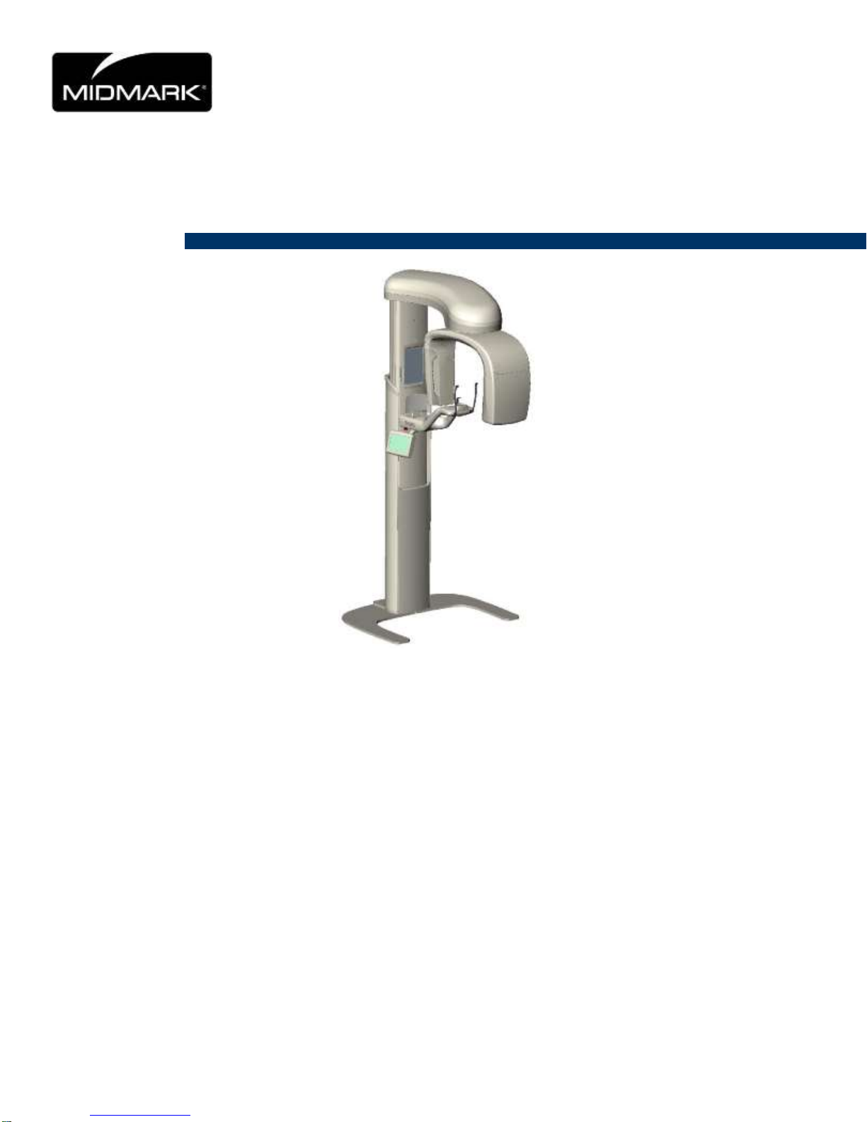
Progeny Vantage Panoramic X-ray System
Installation Guide
ECN: P3774
00-02-1608, Rev. J
Effective Date 02-15-2016
Page 2

2
Table of Contents
Contents ........................................................................................................................................................ 2
1 Regulatory Information ............................................................................................................................... 3
2 Introduction .............................................................................................................................................. 16
Product Description ........................................................................................................................ 16
Disclaimer about the Manual ......................................................................................................... 16
Symbols and Conventions ............................................................................................................. 17
Obtaining Technical Support .......................................................................................................... 18
3 System Overview ..................................................................................................................................... 19
About the Vantage System ............................................................................................................ 19
About the Panoramic X-ray Device ................................................................................................ 19
About the Optional Cephalometric Extension ................................................................................ 20
4 Pre-Installation Planning .......................................................................................................................... 25
Environmental Requirements ......................................................................................................... 25
Support Requirements ................................................................................................................... 26
Power and Cable Requirements .................................................................................................... 26
Space Requirements ...................................................................................................................... 27
Network and System Requirements .............................................................................................. 29
5 Installation ................................................................................................................................................ 30
About Installation ............................................................................................................................ 30
Installing the Vantage Panoramic Device on a Wood Stud Wall ................................................... 31
Installing the Vantage Panoramic Device on a Free Standing Base ............................................. 40
Optional Right Entry Configuration ................................................................................................ 46
6 Installing the Cables ................................................................................................................................. 47
Connecting the Vantage to your network ....................................................................................... 47
Installing the Exposure Button ....................................................................................................... 48
7 Starting Up ............................................................................................................................................... 49
Turning the Vantage System On .................................................................................................... 49
Checking Image Quality ................................................................................................................. 50
8 Vantage Software Client Setup ................................................................................................................ 52
About .............................................................................................................................................. 52
Installation Procedure .................................................................................................................... 52
Connecting to Vantage................................................................................................................... 56
Installing the Vantage Cephalometric Extension on a Vantage Panoramic Device ...................... 59
Progeny Support Information ……………………………………………………………………………84
Page 3

3
1 Regulatory Information
In this Chapter
Indications for Use
Contraindications
Warnings and Precautions
Compliance with Applicable Standards
Certified Components
Device Labeling
EC Declaration of Conformity
EMC Statement
Authorized Representatives
Indications for Use
Statement of Indications for Use
The indications for use of the Progeny Vantage® Panoramic X-ray System are to
provide dental radiographic examination and diagnosis of diseases of the teeth,
jaw, and oral structures. When the system is equipped with the Cephalometric
option, the system will also provide cephalometric radiographic examinations for
the use in orthodontic treatment planning and evaluation.
Guidelines for Patient Selection
The guidelines for use of the Progeny Vantage® Panoramic Extraoral X-ray
System are described in the “ADA/FDA Guide to Patient Selection for Dental
Radiographs.” This device is to be operated only for the intended use as
indicated by prescription of a qualified dental practitioner.
Contraindications
None known at this time.
Adverse Reactions
None known at this time.
Indications of Sterility
This production is not provided sterile. See Maintenance section of this Manual.
Page 4

Progeny Vantage Panoramic X-ray System Installation Guide
4
Warnings and Precautions
Radiation Safety
Only qualified and authorized personnel may operate this equipment observing
all laws and regulations concerning radiation protection.
The operator during X-ray production must remain 2 m [6 ft.] from the focal
spot and the X-ray beam for protection.
Full use must be made of all radiation safety features on the equipment.
Full use must be made of all radiation protection devices, accessories, and
procedures available to protect the patient and operator from X-ray
radiation.
Electrical Safety
Only qualified and authorized service personnel should remove covers on
the equipment.
This equipment must only be used in rooms or areas that comply with all
applicable laws and recommendations concerning electrical safety in rooms
used for medical purposes, e.g., IEC, US National Electrical Code, or VDE
standards concerning provisions of an additional protective earth (ground)
terminal for power supply connection.
Before cleaning or disinfecting, this equipment must always be turned off.
The Progeny Vantage® X-ray System is ordinary medical equipment without
Explosion Safety
This equipment must not be used in the presence of flammable or potentially
explosive gases or vapors, which could ignite, causing personal injury and/or
damage to the equipment. If flammable disinfectants are used, the vapor must be
allowed to disperse before using the equipment.
Damage and Injury
Do not place permanent or non-mobile structures beneath the device. Device
movement may result in damage to the device or structure, or in injury to the
operator or patient.
Cleanliness
To prevent cross contamination, always clean the patient contact areas and
always install a fresh protective sheath over the bite guide before positioning a
patient. The sheath recommended for this application is the TIDI Products, part
number 21008.
protection against ingress of liquids. To protect against short-circuit and
corrosion, no water or any other liquid should be allowed to leak inside the
equipment.
Page 5

Progeny Vantage Panoramic X-ray System Installation Guide
5
Laser Safety
Do not stare into the beam. Do not place eyes closer than
100 mm. This equipment contains class 2 lasers of 3 mW
output at 650 nm. The beam is a 40° fan line. The lensing on the laser is not
removable. Laser on time does not exceed 100 seconds.
Use of procedures other than those contained within this
manual may result in exposure to damaging laser light.
Page 6

Progeny Vantage Panoramic X-ray System Installation Guide
6
Compliance with Applicable Standards
Standard
Content
IEC 60825-1:2001
Safety of Laser Equipment
IEC 60601-1
Medical electrical equipment - Part 1: General
requirements for basic safety and essential
performance
IEC 60601-1-1
Medical electrical equipment - Part 1-1:
General requirements for safety - Collateral
standard: Safety requirements for medical
electrical systems
IEC 60601-2-7
Medical electrical equipment - Part 2-7:
Particular requirements for the safety of highvoltage generators of diagnostic X-ray
generators
IEC 60601-2-28
Medical electrical equipment - Part 2-28:
Particular requirements for the safety of X-ray
source assemblies and X-ray tube assemblies
for medical diagnosis
IEC 60601-1-3
Medical electrical equipment – Part 1-3:
General requirements for radiation protection
in diagnostic X-ray equipment
IEC 60601-1-2
EMI/RFI
CAN/CSA 22.2 No.
601.1-M90
Canadian standard for medical electrical
equipment
IEC 60601-2-32:
1994
Medical electrical equipment - Part 2-32:
Particular requirements for the safety of
associated equipment of X-ray equipment
Radiation Protection
The certified components of the Progeny Vantage Panoramic Dental X-ray
System comply with Radiation Performance Standards 21 CFR, Subchapter J, at
the time of manufacture.
Performance Standards
Page 7

Progeny Vantage Panoramic X-ray System Installation Guide
7
Certified Components
Component
Reference Number
Vantage System, Domestic
60-A0001
Sensor Assembly, Panoramic
60-A1010
Ceph Extension, with Sensors
(option)
60-A1009
Pan tube head assembly
60-A1014
Primary collimator assembly
60-A2009
Pan X-ray power supply
assembly
60-A2035
Sensor Assembly,
Cephalometric (option)
60-A1004
Collimator, secondary, Ceph
(option)
60-F4051
Page 8
Progeny Vantage Panoramic X-ray System Installation Guide
8
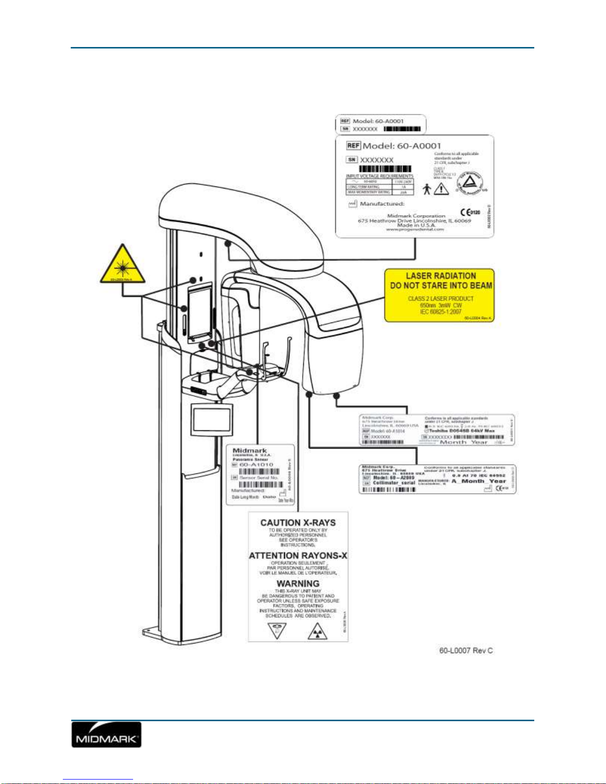
Device Labeling
Page 9
Progeny Vantage Panoramic X-ray System Installation Guide
9
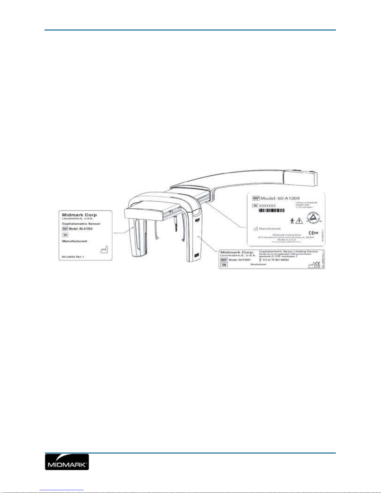
Optional Cephalometric Extension Labeling
Page 10

Progeny Vantage Panoramic X-ray System Installation Guide
10
EC Declaration of Conformity
Page 11

Progeny Vantage Panoramic X-ray System Installation Guide
11
Name and Description
of Product
Progeny Vantage Panoramic Dental X-ray System
Catalog V5000 US Domestic Market
Model 60-A0001 system
Catalog V5100 Export Market
Model 60-A0001 system
Catalog: V5050 Progeny Vantage Panoramic with Ceph Sensor, Domestic
Model: 60-A0008
Catalog: V5150 Progeny Vantage Panoramic with Ceph Sensor, Export
Model : 60-A0008
Catalog: V5000C Progeny Vantage Panoramic with Cephalometric
Extension, 2 Sensor System, Domestic
Model: V5000 + C6000
Catalog: V5100C Progeny Vantage Panoramic with Cephalometric
Extension, 2 Sensor System, Export
Model: V5100 + C6000
Catalog: V5050C Progeny Vantage Panoramic with Cephalometric
Extension, 1 Sensor System, Domestic
Model: V5050 + C4000
Catalog: V5150C Progeny Vantage Panoramic with Cephalometric
Extension, 1 Sensor System, Export
Model: V5150 + C4000
Catalog: C6000 Cephalometric Extension with Sensor
Model: 60-A1009
Catalog: C4000 Cephalometric Extension without Sensor
Model: 60-A1019
Catalog: Ceph Sensor only
Model: 60-A1004
Catalog: Panoramic Sensor
Model: 60-A1010
Class: llb
Reference Numbers to
which Conformity is
Declared
The following regulatory documents apply:
UL 2601-1
IEC 60601-1-2
IEC 60601-1-3
IEC 60601-2-7
IEC 60601-2-28
IEC 60601-2-32
IEC 60825-1
Medical Device Directive
ISO 13485
Machinery Directive
Page 12

Progeny Vantage Panoramic X-ray System Installation Guide
12
Declaration
Midmark Corporation declares that the products described herein meet all
the applicable Essential Requirements of the EC Medical Device Directive
93/42/EEC in Annex I. For Class IIb products described herein, the product
is manufactured, inspected, tested, and released in accordance with the
approved quality assurance system established in accordance with ISO
13485 and Annex II of the EC Medical Device Directive under the
Supervision of the SGS United Kingdom Ltd., a Notified Body.
Contact
Technical Support
Midmark Corporation
Phone: 800-MIDMARK (1-800-643-6275)+1 847-415-9800
Fax: 847-415-9801
imagingtechsupport@midmark.com
Hours: 8:00 a.m. – 5:00 p.m. Central Time
Page 13

Progeny Vantage Panoramic X-ray System Installation Guide
13
EMC Statement
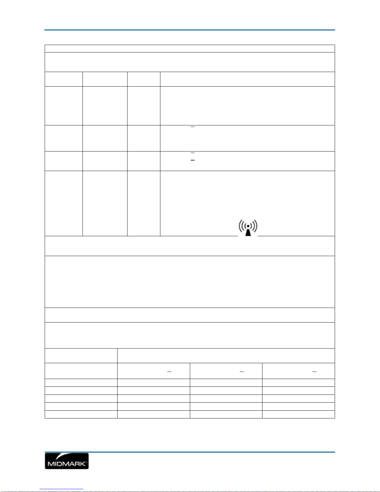
Guidance and manufacturer's declaration - electromagnetic emissions
The Progeny Vantage Dental X-ray System is intended for use in the electromagnetic environment specified below.
The customer or the user of the Progeny Vantage Dental X-ray System should assure that it is used in such an
environment.
Emission test
Compliance
Electromagnetic environment – guidance
RF emission
CISPR 11
Group 1
The Progeny Vantage Dental X-ray System uses RF energy only for its
internal function. Therefore, its RF emissions are very low and are not
likely to cause any interference in nearby electronic equipment.
RF emission
CISPR 11
Class B
The Progeny Vantage Dental X-ray System is suitable for use in all
establishments, including domestic establishments and those directly
connected to the public low-voltage power supply network that supplies
buildings used for domestic purposes.
Harmonic emission
IEC 61000-3-2
Class A
Voltage
fluctuations/ flicker
emissions
IEC 61000-3-3
Complies
Guidance and manufacturer's declaration - electromagnetic immunity
The Progeny Vantage Dental X-ray System is intended for use in the electromagnetic environment specified below.
The customer or the user of the Progeny Vantage Dental X-ray System should assure that it is used in such an
environment.
Immunity test
IEC 60601 test level
Compliance
level
Electromagnetic
environment – guidance
Electrostatic discharge
(ESD)
IEC 61000-4-2
± 6 kV contact
± 8 kV air
± 6 kV contact
± 8 kV air
Floors should be wood, concrete or
ceramic tile. If the floors are covered
with synthetic material, the relative
humidity should be at least 30%.
Electrical fast
transient/burst
IEC 61000-4-4
± 2 kV for power supply lines
± 1 kV for input/output lines
± 2 kV for
power supply
lines
± 1 kV for
input/ output
lines
Mains power quality should be that of
a transient/ burst supply lines typical
commercial or hospital environment.
Surge
IEC 61000-4-5
± 1 kV line(s) to line(s)
± 2 kV line(s) to earth
Not Applicable.
Voltage dips,
interruptions, and
voltage variations on
power supply input
lines
IEC 61000-4-11
< 5% UT (>95% dip in UT) for
0.5 cycle
< 40% UT (60% dip in UT) for
5 cycles
< 70% UT (30% dip in UT) for
25 cycles
< 5% UT (>95% dip in UT) for
5 s
Not Applicable.
Power frequency
(50/60 Hz) magnetic
field
IEC 61000-4-8
3 A/m
3 A/m
Power frequency magnetic fields
should be at levels characteristic of a
typical location in a typical commercial
or hospital environment.
NOTE: UT is the a.c. mains voltage prior to application of the test level.
Information regarding potential EMC interference and advice for avoidance
The Progeny Vantage Panoramic Dental X-ray System is considered as non-life-supporting equipment.
While using the Progeny Vantage X-ray System adjacent to other equipment, the configuration should be
carefully adjusted to ensure that electromagnetic interference (EMI) does not degrade performance.
Specifically, mobile RF communications equipment can effect medical electrical equipment. Please refer
to the EMC table below.
Page 14
Progeny Vantage Panoramic X-ray System Installation Guide
14
Guidance and manufacturer's declaration - electromagnetic immunity
The Progeny Vantage Dental X-ray System is intended for use in the electromagnetic environment specified below.
The customer or the user of the Progeny Vantage Dental X-ray System should assure that it is used in such an
environment.
Immunity
test
IEC 60601
test level
Complian
ce level
Electromagnetic environment – guidance
Portable and mobile RF communications equipment should be used
no closer to any part of the Progeny Vantage Dental X-ray System,
including cables, than the recommended separation distance
calculated from the equation applicable to the frequency of the
transmitter.
Recommended separation distance:
Conducted
RF
IEC 610004-6
3 V
150 kHz to
80 MHz
3 V
𝑑 = 1.2 ×√𝑃
Radiated RF
IEC 610004-3
3 V/m
80 MHz to
2.5 GHz
3 V/m
𝑑 = 1.2 ×√𝑃 80 MHz to 800 MHz
𝑑 = 2.3 ×√𝑃 800 MHz to 2.5 GHz
Where P is the maximum output power rating of the transmitter in
watts (W) according to the transmitter manufacture and d is the
recommended separation distance in meters (m).
Field strengths from fixed RF transmitters, as determined by an
electromagnetic site survey, a should be less than the compliance
level in each frequency range. b
Interference may occur in the vicinity of equipment marked with the
following symbol:
NOTE 1: At 80 MHz and 800 MHz, the higher frequency range applies.
NOTE 2: These guidelines may not apply in all situations. Electromagnetic propagation is affected by absorption and
reflection from structures, objects, and people.
a
Field strengths from fixed transmitters, such as base stations for radio (cellular/cordless) telephones and land mobile
radios, amateur radio, AM and FM radio broadcast and TV broadcast cannot be predicted theoretically with accuracy.
To assess the electromagnetic environment due to fixed RF transmitters, an electromagnetic site survey should be
considered. If the measured field strength in the location in which the Progeny Vantage Dental X-ray System is used
exceeds the applicable RF compliance level above, the Progeny Vantage Dental X-ray System should be observed
to verify normal operation. If abnormal performance is observed, additional measures may be necessary, such as reorienting or relocating the Progeny Vantage Dental X-ray System.
b
Over the frequency range 150 kHz to 80 MHz, field strengths should be less than [V1] V/m.
Recommended separation distances between portable and mobile RF communications equipment and
Progeny Vantage Dental X-ray System
The Progeny Vantage Dental X-ray System is intended for use in the electromagnetic environment in which radiated
RF disturbances are controlled. The customer or the user of the sensor can help prevent electromagnetic interference
by maintaining a minimum distance between portable and mobile RF communications equipment (transmitters) and
the sensor as recommended below, according to the maximum output power of the communications equipment.
Rated maximum output
power of transmitter, W
Separation distance according to frequency of transmitter
m
150 kHz to 80 MHz
𝑑 = 1.2 ×
√
𝑃
80 MHz to 800 MHz
𝑑 = 1.2 ×
√
𝑃
80 MHz to 2.5 GHz
𝑑 = 2.3 ×
√
𝑃
0.01
0.12
0.12
0.23
0.1
0.37
0.37
0.74 1 1.17
1.17
2.34
10
3.69
3.69
7.38
100
11.67
11.67
23.34
Page 15

Progeny Vantage Panoramic X-ray System Installation Guide
15
For transmitters rated at a maximum output power not listed above, the recommended separation distance d in
meters (m) can be determined using the equation applicable to the frequency of the transmitter, where P is the
maximum output power rating of the transmitter in watts (W) according to the transmitter manufacturer.
NOTE 1: At 80 MHz and 800 MHz, the separation distance for the higher frequency range applies.
NOTE 2: These guidelines may not apply in all situations. Electromagnetic propagation is affected by absorption and
reflection from structures, objects, and people.
Authorized Representatives
North America
MIDMARK CORPORATION
675 Heathrow Dr.
Lincolnshire, Illinois 60069 U.S.A.
Phone: 800-MIDMARK (1-800-643-6275)
+1 847-415-9800
Fax: 847-415-9801
Europe
CE Partner 4U
Esdoornlaah 13
3951DB Maarn
The Netherlands
www.cepartner4u.eu
Page 16

16
2 Introduction
In this Chapter
Product Description
Disclaimer about the Manual
Symbols and Conventions
Obtaining Technical Support
Product Description
The Progeny Vantage Panoramic X-ray System is an easy to use and easy to
install digital panoramic X-ray system.
The panoramic X-ray provides a broad overview of the teeth, jaw, and oral
structure of the entire mouth. The X-ray image supplies information about the
teeth, upper and lower jawbone, sinuses, and other hard and soft tissues of the
head and neck. The panoramic digital receptor is contained in a C-arm that
moves around the patient’s head.
The Vantage System has many applications that include evaluation of third
molars, evaluation of patients with past and present TMJ (temporomandibular
joint) problems, patients who require full or partial removable dentures, dental
implants, or braces, those who are at risk or suspected of having oral cancer or
other tumors of the jaw, those who have impacted teeth, and those who have
had any recent trauma to the face or teeth (i.e., can help identify a fractured jaw).
The optional Cephalometric Extension allows for lateral and PA views of oral
structures. The ceph digital receptor is mounted on a transit rail which scans
horizontally during ceph examinations. Cephalometric images are typically
useful in orthodontic evaluation and treatment.
Disclaimer about the Manual
Midmark pursues a policy of continual product development. Although every
effort is made to produce up-to-date product documentation, this publication
should not be regarded as an infallible guide to current specifications. We
reserve the right to make changes without prior notice. The original language of
this manual is English.
Page 17
Progeny Vantage Panoramic X-ray System Installation Guide
17
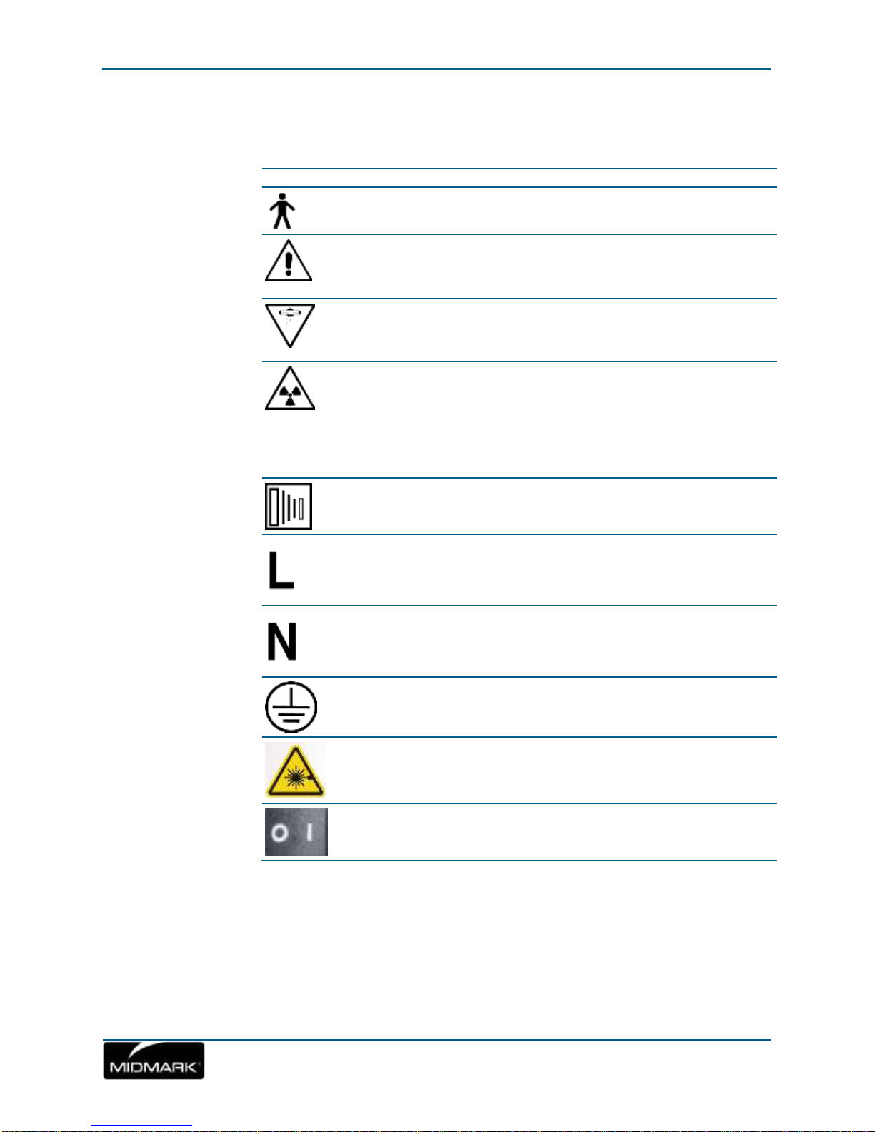
Symbols and Conventions
Symbol
Explanation
Type B: Protection against electric shock (IEC 60601.1-
1988).
Consult written instructions in the User Guide.
ATTENTION RAYONS-X:
OPERATION SEULEMENT PAR DU PERSONNEL
AUTORISE. VOIR MANUEL DE L’OPERATEUR.
WARNING X-RAY
THIS X-RAY UNIT MAY BE DANGEROUS
TO PATIENT AND OPERATOR UNLESS
SAFE EXPOSURE FACTORS AND
OPERATING INSTRUCTIONS ARE
OBSERVED.
X-RAY EMISSION
Mains HOT WIRE
Mains NEUTRAL WIRE
Earth Ground
LASER RADIATION
DO NOT STARE INTO BEAM
CLASS 2 LASER PRODUCT. 650 nm, 3 mW
Power off (circle)
Power on (line)
Page 18

Progeny Vantage Panoramic X-ray System Installation Guide
18
Obtaining Technical Support
For Technical Support, contact:
MIDMARK CORPORATION
675 Heathrow Drive
Lincolnshire, Illinois 60069 U.S.A.
Phone: 888-924-3800 (U.S. and Canada)
+1 847-415-9800 (International)
Fax: 847-415-9810
imagingtechsupport@midmark.com
Hours: 8:00 a.m. – 5:00 p.m. CT
Page 19

19
3 System Overview
In this Chapter
About the Vantage System
About the Panoramic X-ray Device
About the Optional Cephalometric Extension
About the Vantage System
The Progeny Vantage Panoramic X-ray System consists of the panoramic X-ray
device, the exposure button, and a Touch Control Panel.
About the Panoramic X-ray Device
The panoramic X-ray device consists of the telescoping column, the overhead
assembly, the patient positioning table, and the touch control panel.
Telescoping Column
The telescoping column has two main parts: the fixed section and the moving or
telescoping section. The fixed section contains the actuator to control up and
down movement of the panoramic X-ray device. The telescoping section mounts
the patient positioning features. Optical sensors in the telescoping section define
the maximum and minimum extension of the column.
Overhead Assembly
The overhead assembly consists of an overhead arm and C-arm. The overhead
arm supports the C-arm, which rotates. The C-arm includes the tubehead and
the removable sensor. The tubehead produces the X-ray beam, and the sensor
is a digital image receptor.
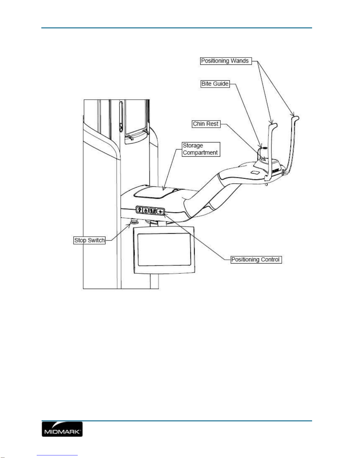
Patient Positioning Table
The patient positioning table guides and supports the patient’s head during
acquisition of panoramic X-ray images by means of the chin rest, bite guide, and
positioning wands. The positioning control on the side of the patient positioning
table has 4 buttons for the operator to control the up/down movement of the
telescoping column, to apply and release the positioning wands, and to turn on
positioning lights. The patient positioning table also contains a storage
compartment.
Touch Control Panel
The touch control panel is mounted on the fixed column section under the patient
positioning table. It is the main user interface for taking X-ray images with the
Vantage System and is activated by touch.
Page 20

Progeny Vantage Panoramic X-ray System Installation Guide
20
Exposure Button
The exposure button is used by the operator to take the X-ray. The basic
configuration consists of an exposure button connected to the panoramic X-ray
device by a coil cord.
Bite Guide
A bite guide helps the patient keep his or her jaw correctly positioned. Additional
bite guides may be obtained from Progeny. Always install a fresh protective
sheath over the bite guide before positioning a patient. The sheath for this
application is the Progeny part number 60-S0027.
Chin Rest
An easily removable chin rest fits into an opening on the patient positioning table.
Additional chin rests may be obtained from Progeny.
TMJ Positioner
A TMJ positioner for TMJ X-rays fits into the patient positioning table. TMJ
positioners are included with the Vantage.
Emergency Stop Switch
The stop switch, mounted under the left side of the patient positioning table near
the telescoping column, is for use by the patient or clinician. Depressing the
button will immediately halt all motor movement. Touching the control panel
surface will also abort any movement. The button can be released by turning the
knob.
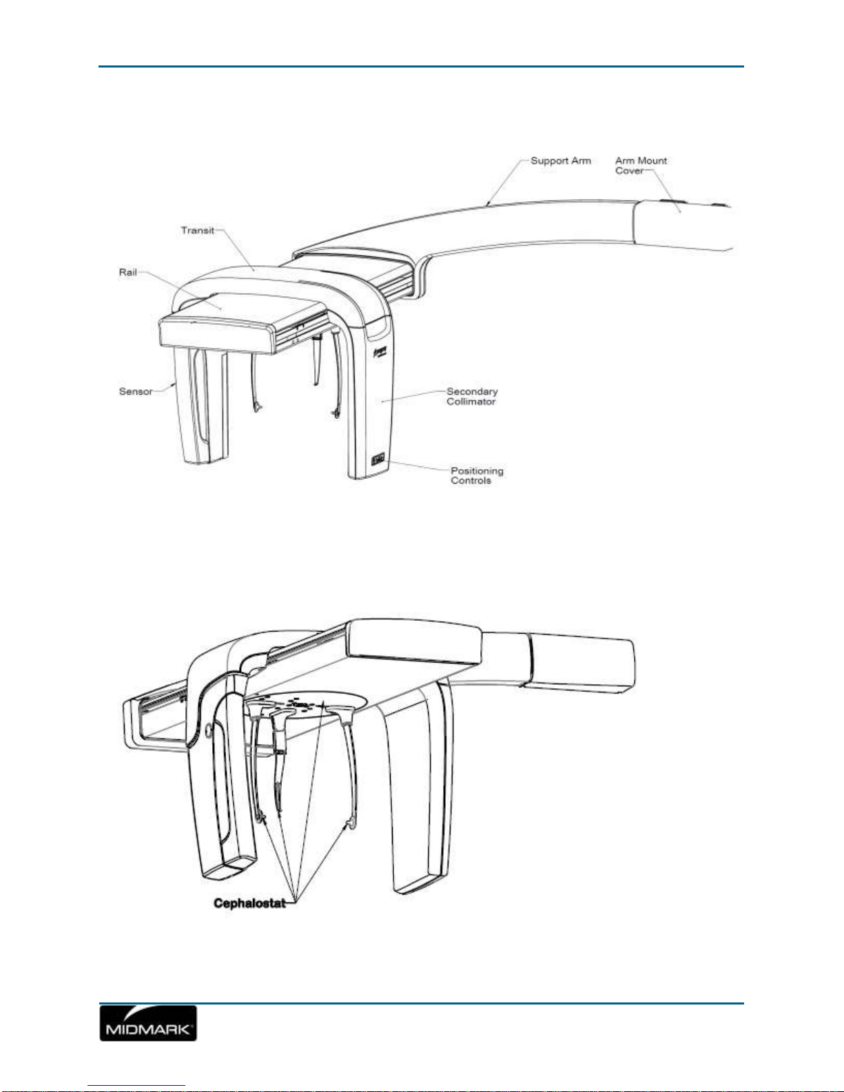
About the Optional Cephalometric Extension
The Cephalometric Extension consists of the support arm, the cephalometric
scanning mechanism and the cephalometric sensor.
Support Arm
The support arm is an aluminum casting that mounts to the panoramic column’s
inner (mobile) component. It mounts via a support casting that allows vertical
adjustment of the position of the cephalometric mechanism. The arm can be
mounted either to the right, or to the left of the column.
Cephalometric Scanning Mechanism
The cephalometric scanning mechanism is comprised of the rail and the transit
assembly. The rail supports the transit mechanism, and houses the motor and
bearings that cause the transit mechanism to move. The transit assembly
mounts the cephalometric sensor and the secondary collimator, and maintains
the alignment of the sensor and secondary collimator to the panoramic
tubehead.
The rail also supports the cephalostat, used to position the patient. The
cephalostat is comprised of two otic positioning posts which adjust to conform to
Page 21

Progeny Vantage Panoramic X-ray System Installation Guide
21
the width of the patients head, and a nasion locator, which adjusts vertically and
laterally to align the patients head. The entire cephalostat rotates in 22.5°
increments to support many cephalometric imaging positions.
Cephalometric Sensor
The cephalometric sensor is similar in appearance to the panoramic sensor, but
houses within a 21cm long digital detector instead of the 14cm digital detector
used for normal panoramic exam. The cephalometric sensor can be used in
place of the panoramic sensor, but the panoramic sensor will not operate as a
cephalometric sensor.
Page 22

Progeny Vantage Panoramic X-ray System Installation Guide
22
Vantage System Panoramic X-ray Device
Page 23
Progeny Vantage Panoramic X-ray System Installation Guide
23
Vantage System Patient Positioning Table
Page 24
Progeny Vantage Panoramic X-ray System Installation Guide
24
Optional Cephalometric Extension
Page 25

25
4 Pre-In stallation Planning
In this Chapter
Environmental Requirements
Support Requirements
Power and Cable Requirements
Space Requirements
Network and System Requirements
Environmental Requirements
Temperature
The Vantage panoramic device is intended for indoor use for normal dental
applications at temperatures in the range +10 C to +35 C (+50 F to +95 F).
Storage temperature range should not exceed -35 C to +66 C (-31 F to +150 F).
Humidity
Humidity should not cause condensation to form on the device. When the device
is being operated, humidity should not exceed 95% RH non-condensing. When
the device is being stored, humidity should not exceed 90% RH non-condensing.
Page 26

Progeny Vantage Panoramic X-ray System Installation Guide
26
Support Requirements
About Support
The Vantage panoramic device is wall mounted. As an alternative, the Vantage
panoramic device can be installed as a free standing unit. If the free standing
installation method is used, the free standing base kit must be attached to the
unit for support.
Wall Mounted Installation
Wall fasteners for the Vantage panoramic device must be able to withstand a 68
kg (150 lb.) shear force and a 180 kg (400 lb.) tensile (pull-out) load. The floor
must be able to support approximately 90 kg (200 lb./sq. ft.) for wall mounted
installation.
Free Standing Installation
The floor must be able to support approximately 158 kg (100 lb./sq. ft.) for free
standing installation. Free standing installation cannot be used for the
Cephalometric Extension.
Power and Cable Requirements
Electrical Outlet Requirements
The Vantage System requires a dedicated, 15 amp minimum circuit. If a fixed
connection is used, the length of the whip must conform to local codes. If a
standard mains receptacle is used, it must be placed within 2 m (6 ft.) of the
device and positioned in compliance with local codes.
Ethernet Connections
Cat 5e grade communications cable is required for connection of the Vantage
panoramic system.
Optional Remote Exposure Switch
If a remote exposure switch is used, a four conductor cable capable of RJ 11
termination is required for installation.
Page 27

Progeny Vantage Panoramic X-ray System Installation Guide
27
Space Requirements
The fully extended column has a maximum height of 236 cm (93 in.) and depth of
121 cm (48 in.). The rotational reach of the overhead arm and C-arm is 108 cm
(48 in.). See the diagram below.
The Vantage panoramic device has an optional right or left entry. The default
configuration is left entry. To configure a right entry, see Optional Right Entry
Configuration in Chapter 6.
Panoramic Space Requirements
Page 28

Progeny Vantage Panoramic X-ray System Installation Guide
28
Page 29

29
Component
Requirement
Computer
Hardware
PC - compatible Pentium 4 / 1.4 GHz or greater computer
Memory
System
2 GB RAM or higher recommended (minimum 1 GB)
Operating
System
Microsoft Windows XP Professional with Service Pack 3;
Microsoft Vista (Business or Ultimate editions); Microsoft
Windows 7 (Professional or Ultimate editions)
Disk Space
450 MB minimum
NOTE: Additional disk space is needed depending on
the size of the practice, the number of images, and other
information you plan to store. Each image is approximately
4 MB. For example, approximately 300 GB are needed to
store 75 000 images.
Display
Settings
1024 x 768 (16 - bit or higher) with 32 MB (or higher) of Video
RAM
NOTE: It is possible to increase these settings based on
the actual video adapter installed. As a rule, the better your
video adapter or capture card the better your images.
Network and System Requirements
The Vantage Software Client requires a computer for it to be installed on and a
network connection to communicate with the Vantage Panoramic.
Network Requirements:
An Ethernet based network connection at 100MBps or higher
A wireless network connection at 802.11n or higher***
***A wireless network connection may introduce speed limitations that can result
in a less than desirable image transmission time
System Requirements:
Page 30

30
5 Installatio n
In this Chapter
About Installation
Installing the Vantage Panoramic Device on a Wood Stud Wall
Installing the Vantage Panoramic Device on a Free Standing Base
Optional Right Entry Configuration
About Installation
The Vantage System panoramic device is preassembled and can be installed in
a few easy steps. It has been designed to be installed by one person with an
assistant in one hour, assuming that all pre-installation requirements have been
met. Checking the image alignments can take an additional hour.
Check Pre-installation Requirements
Prior to beginning the installation, be sure that all pre-installation requirements
have been completed. This includes confirming that the wall and floor support
requirements are adequate for mounting the Vantage panoramic device, that the
electrical requirements are met, and that wire locations are proper.
Optional Right Entry Configuration
The Vantage System is packaged with a left entry but can be configured with a
right entry. To configure a right entry, see Optional Right Entry Configuration in
this chapter.
Page 31

Progeny Vantage Panoramic X-ray System Installation Guide
31
Installing the Vantage Panoramic Device on a Wood Stud
Wall
Preparing to Install the Vantage Panoramic Device
Gather Tools
Level
2 mm hex key
4 mm hex key
6.3 mm (1/4 in.) pilot hole drill
9.5 mm (3/8 in.) pilot hole drill (masonry bit for cement floor)
14 mm (9/16 in.) socket wrench (for cement or wood floor)
Unpack the Hardware Kit
Hardware for wall (wood mount): 1 wall bracket, 2 lag bolts, and 2 washers
Hardware for cement floor: 2 cement anchors, 2 nuts, and 2 washers
Hardware for wood floor: 2 lag bolts and two washers
Hardware for attaching wall bracket to column: 2 clamps and 2 screws
Unpack the Removable Parts Kit
Chin rest
2 wands
Bite guide
Page 32

Progeny Vantage Panoramic X-ray System Installation Guide
32
Cautions
When using lag screws as the method of attachment, it is imperative to consider
the full scope of the task. Several factors must be considered for safe, permanent
installations. Some of the key issues are below:
Lumber commonly used in construction projects can be different from
location to location.
The grade, age, position, and overall condition of wood can vary greatly.
The attachment stud may have additional, hidden loads.
The location of the pilot hole with respect to the center of the stud will affect
the load bearing ability.
The size of the pilot hole required for the lag screw will be different based on
the grade, age, and condition of the lumber.
Never over-tighten the lag screw as this will weaken the mechanical
connection (18 ft.-lb. maximum).
Lumber with splits or cracks should not be used for attachment.
Plywood, particle board, or similar construction materials should not be
used for attachment.
Progeny provides fasteners for average installations. Based on specific
installation conditions, it may be necessary to choose an alternate fastener or
fastening methods.
Seek the advice of a professional structural engineer to clarify any issues
before the installation.
About the Order of Installation
For convenience and access, Progeny recommends the following order of
installation described in the following sections:
Remove the shipping brackets
Attach the power
Attach the bracket to the wall
Snap the Vantage panoramic device in place
Plumb the Vantage panoramic device and attach the clamps
Mount the Vantage panoramic device to the floor
Page 33

Progeny Vantage Panoramic X-ray System Installation Guide
33
Remove the Shipping Brackets
Before attaching power, you need to remove the shipping brackets.
1. Remove the overhead top cover and remove the three orange shipping bolts
from the overhead pivot area.
Overhead Top Cover
2. Remove the 4 bolts holding the orange shipping bracket in place as shown in
the following figure.
Remove Aluminum Shipping Bracket
Page 34

Progeny Vantage Panoramic X-ray System Installation Guide
34
Attach the Bracket to the Wall
The mounting bracket is a guide for locating where to drill the holes used to
mount the Vantage panoramic device to the wall. Carefully placing the mounting
bracket on the wall will help to insure correct installation of the Vantage
panoramic device.
1. Center the bracket on the studs.
2. Hold the bracket so that it is 121 cm (47 ½ in.) from the floor and mark one of
the bracket holes.
3. Drill a 6.3 mm (1/4 in.) hole.
4. Select the 2 wall mount washers and the 2 lag bolts from the hardware kit.
5. Put 1 lag bolt through the washer and bracket mounting hole and loosely
tighten the bolt.
6. Lift up the other side of the bracket and level it.
7. Mark the second hole and drill it.
8. Put the second lag bolt through the second washer and second bracket
mounting hole and loosely tighten the bolt.
9. Place a level on the top of the bracket and level the bracket.
10. Tighten the bolts to 14-18 ft. lb. maximum.
Test the Bracket
Page 35

Progeny Vantage Panoramic X-ray System Installation Guide
35
Snap the Vantage Panoramic Device in Place
The Vantage panoramic device and bracket are designed to snap together when
correctly aligned and firm pressure is applied. This snap holds the device in place
while you complete the installation.
1. Lift up and move the Vantage panoramic device to the mounting wall with the
back positioned towards the wall mounted bracket.
2. Line up the Vantage panoramic device with the wall mounted bracket and
snap the device into place, making sure the device snaps solidly.
CAUTION! The snap partially secures the Vantage panoramic
device. The clamps and floor mount steps must be
completed to hold the device in place.
Vantage Panoramic Device and Wall Bracket
Page 36

Progeny Vantage Panoramic X-ray System Installation Guide
36
Plumb the Vantage Panoramic Device and Attach the Clamps
The Vantage panoramic device and wall bracket must be joined with 2 clamps.
This requires a process of alternately screwing the clamps into place and
plumbing the device.
1. Select 2 clamps and 2 screws from the mounting hardware kit.
Clamp and Screw
2. Hold 1 clamp in place, aligning it with one of the small holes in the bracket.
Insert a screw through the wall bracket hole and the Vantage panoramic
device hole. Tighten the screw using a 4 mm hex key. Do not tighten
completely.
Clamp Placement
Page 37

Progeny Vantage Panoramic X-ray System Installation Guide
37
3. Hold a level vertically against the column and move the Vantage panoramic
device on the floor until it is plumb.
Column Test
4. Once the column is plumb, repeat the procedure with the second clamp. Do
not tighten completely.
5. Do a final level test before completely tightening the clamp screws.
Page 38

Progeny Vantage Panoramic X-ray System Installation Guide
38
Mount the Vantage Panoramic Device to the Floor
Use the floor base as a template to drill holes in the floor. You do not need to
move the Vantage panoramic device for this procedure. Ensure that the device is
positioned vertically before drilling holes.
Note
To install the Vantage panoramic device on a free standing base, see Installing
the Vantage Panoramic Device on a Free Standing Base in this chapter.
1. Select 2 cement anchors, 2 washers, and 2 nuts from the hardware kit. For
wood floors, select 2 lag bolts and 2 washers.
2. Drill through 1 hole in the floor base of the Vantage panoramic device using
an 9.5 mm (3/8 in.) masonry bit. For wood floors, use a 6.3 mm (1/4 in.) bit.
Drilling through Floor Base Hole
Page 39

Progeny Vantage Panoramic X-ray System Installation Guide
39
3. Insert 1 cement anchor through the hole in the plate. Assemble 1 nut and 1
washer on top of the cement anchor and tighten. Ensure that the anchor is
fully seated in the hole. For wood floors, assemble 1 lag bolt and 1 washer
and insert the lag bolt and washer through the hole in the plate. Screw the
lag bolt partially into the hole using a socket wrench.
4. Repeat the process for the second anchor, nut, and washer. For wood floors,
repeat the process for the second lag bolt and washer.
Inserting Anchor
5. Tighten the anchors using a 14 mm (9/16 in.) socket wrench. For wood
floors, tighten the lag bolts using a 14 mm (9/16 in.) socket wrench (same
size as used for cement).
Tightening Anchor
Page 40

Progeny Vantage Panoramic X-ray System Installation Guide
40
Installing the Vantage Panoramic Device on a Free Standing
Base
Preparing to Install the Vantage Panoramic Device on a Free Standing
Base
Gather Tools
Level
2 mm hex key
4 mm hex key
8 mm hex key
17 mm socket wrench
Unpack the Hardware Kit
2 kinds of bolts: 4 each
8 levelers
8 leveler plugs
Unpack the Removable Parts Kit
Chin rest
2 wands
Bite guide
About the Order of Installation
For convenience and access, Progeny recommends the following order of
installation described in the following sections:
Arrange the free standing base halves and levelers
Attach the Vantage panoramic device to the free standing base
Remove the shipping brackets
Attach the power
Position and mount the Vantage panoramic device to the floor
Page 41

Progeny Vantage Panoramic X-ray System Installation Guide
41
Arrange the Free Standing Base Halves and Levelers
Prepare the free standing base for attachment to the Vantage panoramic device
using the following steps:
1. Remove the free standing base halves from the packaging.
2. Install the levelers in the holes as shown below.
3. Arrange the base halves as shown below, with the levelers in contact with
the flooring.
Free Standing Base Halves and Levelers
Page 42

Progeny Vantage Panoramic X-ray System Installation Guide
42
Attach the Vantage Panoramic Device to the Free Standing Base
To attach the free standing base to the Vantage panoramic device, set the
Vantage panoramic device on top of the base halves and install the bolts and
bracket, using the following steps:
1. Move the Vantage panoramic device over the bases with the overhead
pointing the same direction as the legs of the bases.
2. Install the bolts and bracket as shown below, back and front views.
Attaching Vantage Panoramic Device to Free Standing Base:
Back View
Page 43

Progeny Vantage Panoramic X-ray System Installation Guide
43
Attaching Vantage Panoramic Device to Free Standing Base:
Front View
Page 44

Progeny Vantage Panoramic X-ray System Installation Guide
44
Remove the Shipping Brackets
Before attaching power, you need to remove the shipping brackets.
1. Remove the overhead top cover and remove the three orange shipping bolts
from the overhead pivot area.
Overhead Top Cover
2. Remove the 4 bolts holding the orange shipping bracket in place as shown in
the following figure.
Remove Aluminum Shipping Bracket
Page 45

Progeny Vantage Panoramic X-ray System Installation Guide
45
Position and Mount the Vantage Panoramic Device to the Floor
To attach the Vantage panoramic device to the floor, you need move the unit into
position, level the unit, and mount it to the floor using the following steps:
1. Move the Vantage panoramic device on its base into position, and use an 8
mm hex wrench to level the device, ensuring that all levelers are in contact
with the flooring.
2. Fix the unit to the floor with the flooring appropriate fasteners through the
holes in the center of the levelers.
Page 46

Progeny Vantage Panoramic X-ray System Installation Guide
46
Optional Right Entry Configuration
The Vantage panoramic device is delivered with left entry. To configure with a
right entry, remove and rotate the Frankfort Plane Laser Assembly using these
steps:
1. To access the Frankfort Plane Laser Assembly, remove the cover from the
telescoping section of the column.
2. Disconnect the laser wires.
3. To access the new screw holes where you will install the assembly, remove
the small cover on the left side of the mirror assembly (as viewed from the
back of the column). Set the small cover aside for later assembly.
4. Remove the 2 screws from the Frankfort Plane Laser Assembly and lift the
assembly out. Set the screws aside for later assembly.
Frankfort Plane Laser Assembly
5. Rotate the Frankfort Plane Laser Assembly 180 degrees so that it is upside
down.
6. Install the Frankfort Plane Laser Assembly on the left side of the column (as
viewed from the back of the column) using the 2 screws.
7. Place the small cover over the screw holes on the right side (as viewed from
the back).
8. Reconnect the laser wires.
9. Replace the column cover.
Page 47

Progeny Vantage Panoramic X-ray System Installation Guide
47
6 Installing the Cables
In this Chapter
Connecting the Vantage to Your Network
Installing the Exposure Button
Connecting the Vantage to your network
The Vantage System requires a PC that serves as a workstation to receive
images from the Vantage panoramic device. The Vantage must be connected to
the same network as the designated workstation in order to connect and receive
an image.
1. Attach the PC Ethernet cable to the network connection port on the back of
the column and the other end into your network wall jack
Cable Connecting Ports
Page 48

Progeny Vantage Panoramic X-ray System Installation Guide
48
Installing the Exposure Button
The exposure button is used to take the X-rays. The basic configuration is to
connect the button to the Vantage panoramic device by means of a coil cord.
Attach the Exposure Button to the Vantage Panoramic Device
To attach the exposure button, insert the coil cord into one of the exposure
switch connections on the column shown in the figure above. The exposure
switch connections are the top 2 ports.
Mount the Exposure Button
The exposure button comes with double stick tape and a hole for a screw, if
desired, for mounting. It can be mounted to the fixed portion of the column or to a
wall.
1. To mount the exposure button using the double stick tape, remove the
protective backing covering the adhesive mount.
2. Firmly press the mount to the wall or surface as shown in the figure below.
Exposure Button Mounted
Page 49

49
7 Starting Up
In this Chapter
Turning the Vantage System On
Checking Image Quality
Progeny Support Information
Turning the Vantage System On
You can turn on the Vantage panoramic X-ray device first or the client software
first (see chapter 8 Vantage software client setup). Make sure that all shipping
brackets have been removed.
1. To turn on the Vantage panoramic device, press the on/off switch located at
the back of the stationary column on top of the box of connections.
Vantage Panoramic Device with On/Off Switch
When you turn on the Vantage panoramic device, the touch control panel
displays a “Start Up” screen. The Vantage panoramic device goes through a
self diagnostic procedure as part of the startup process.
2. If the Client software is not running, launch it and open the image acquisition
software.
Page 50

Progeny Vantage Panoramic X-ray System Installation Guide
50
Checking Image Quality
An image quality phantom is available from Progeny. The phantom simulates the
position of average human teeth roots, and markers allow you to check the
position of the focal trough. To check for image quality, you need to take an X-ray
exposure with the image phantom and then view the image, checking it
according to some specific tests. The Cephalometric imaging phantom is
included with Cephalometric Extension option.
Install the Panoramic Image Phantom
The Vantage panoramic device is designed so that the chin rest accessory can
easily be switched with the image phantom.
1. To install the image phantom, lift the chin rest from the chin rest hole on the
patient positioning table.
2. Set the image phantom in the chin rest hole.
Image Checks
The following checks for image quality are performed on the image after
exposing the phantom. In general, each individual line should be sharp where the
lines cross the center of the image, and they should blur out above the center
line.
1. Verify that the semi-projections b = c +/- 3 mm (nominal value with the
central vertical line well focused) = 80 mm.
2. Verify that line “a” is vertical +/-3 degrees with respect to the horizontal line
“d”.
3. Verify that line “d” is horizontal and flat within a band of 6 mm.
Page 51

Progeny Vantage Panoramic X-ray System Installation Guide
51
4. Verify that the darkened area is centered in respect to the central vertical line
“a” with a tolerance of +/- 4 mm.
5. Verify that the central vertical line is well focused and adjacent balls are
round.
X √ X
Page 52

Progeny Vantage Panoramic X-ray System Installation Guide
52
8 Vantage Software Client Setup
When installing the software it is assumed that previous versions of the
Progeny Device Suite and Progeny Imaging image management
software are not present.
NOTE: Proper operation requires any previous
version of Progeny Device Suite and Progeny
Imaging to be removed (uninstalled) prior to the
installation process to begin.
Execute the following steps:
Insert the USB Flash Drive into an available USB port on your
computer and allow the computer to recognize the flash drive.
In this Chapter
About
Installation Procedure
Connecting to Vantage
About
Vantage acts as a “network appliance” that connects directly to your network. In
order to receive x-ray images you must designate at least one workstation on
your network to receive them.
Installation Procedure
Page 53

Progeny Vantage Panoramic X-ray System Installation Guide
53
The main screen of the installation software is shown on Figure 1. If
the software on the USB flash drive does not start automatically,
navigate to Windows Explorer™ and select the “Progeny” drive
letter. Browse to the content of the flash drive and start “Setup.exe”.
This step begins the installation process.
NOTE: The installation software requires
Microsoft .NET Framework revision 3.5. This
software will be installed if it is not yet present to
the operating system. Follow all on screen
prompts.
NOTE: If the intended configuration is based on
Windows XP, the Service Pack 3 update is
required. This update is included on the USB
flash drive and can be installed from folder
named ‘Utilities’. Another option is to use the
Windows update tool provided by Microsoft.
Figure 1: Main screen of the Installation software
Page 54

Progeny Vantage Panoramic X-ray System Installation Guide
54
Start the installation process by clicking on ‘Install Progeny Device
Suite’ button (Figure 2).
NOTE: The installed software requires multiple
software components that may already be
available in your system. These components will
be installed if they are not yet present. Follow all
on screen prompts.
Figure 2: Starting the Progeny Device Suite installation
The screen on Figure 3 will be displayed. Choose Vantage Pan and
all other device families that have to be supported by the Imaging
Software.
Figure 3: Selecting the device families to be installed
Page 55

Progeny Vantage Panoramic X-ray System Installation Guide
55
A green check mark next to the ‘Install Progeny Device Suite’ button
will appear when Progeny Device Suite installation is completed.
Continue by installing Progeny Imaging software by clicking on
‘Install Progeny Imaging’ button (Figure 4) and follow the prompts on
the screen to perform the installation.
Figure 4: Starting the Progeny Imaging installation
Green check marks next to each of the ‘Install Progeny Device Suite’
and ‘Install Progeny Device Suite’ buttons will appear when both the
Progeny Device Suite and Progeny Imaging are installed (Figure 5).
Figure 5: Progeny Device Suite and Progeny Imaging are installed
Page 56

Progeny Vantage Panoramic X-ray System Installation Guide
56
Connecting to Vantage
Connecting your computer to the Vantage system can be setup either through
Progeny Imaging image management software or through Progeny’s TWAIN
interface.
If you are using Vantage Pan from a 3rd party application you need to
open Progeny’s TWAIN interface to connect to the Vantage system.
Some image management programs also support Vantage integration.
See your image management software support for more information on
how to access the Vantage.
Select “Vantage Pan” in the device drop down if it has not already been
selected
To access device configuration:
o TWAIN: Click the device configuration icon
o Progeny Imaging: In the top menu browse to Tools > Devices >
Device Configuration
If you have already connected to a device it will be listed in the Server
Connection section. Click the “Connect” button.
Page 57

Progeny Vantage Panoramic X-ray System Installation Guide
57
The “Select Pan Server” window will automatically discover the Vantages
in your network. Highlight the vantage you want to connect to and click
the “Select” button.
o Optional User Name: The User Name field is what’s used to
identify your Vantage Client in the network. The default is your
computer’s name.
o Optional Network Adapters: Progeny Device Suite will
automatically detect the most suitable network adapter on your
computer for connecting to the Vantage. If your Vantage is not
automatically discovered click the “Net Config” button to select a
specific network adapter.
Page 58

Progeny Vantage Panoramic X-ray System Installation Guide
58
Once returned to Device Configuration screen the Vantage you selected
will be visible in the “Server Connection” section. Click the “Close” button
to complete the connection.
Once you close Device Configuration and you are back at the client
application the light for “Vantage Pan” should now turn green.
At this point you can take images with the Vantage Panoramic and they
will be delivered to the client. You can repeat these steps at any time to
connect to another Vantage panoramic device.
Page 59

Progeny Vantage Panoramic X-ray System Installation Guide
59
Installing the Cephalometric Extension
3 mm Allen wrench
4 mm Allen wrench
5 mm Allen wrench
6 mm Allen Wrench
13 mm open end wrench
Bubble Level
½ inch open end wrench
Phillips head screw driver
Torx set
Select “Service” on the lower left
B
Select “Options” on the lower right of the
display.
A
1
2
Enter 77469 and Select OK.
C
1. Select the system information symbol on
the bottom as shown.
2. Select System Center
D
Tools Required:
If you are upgrading an existing Vantage in the field for the Cephalometric, the debug adapter will be
required to upgrade the RTC and the Operator Panel.
Parts Required:
C6000 – Progeny Cephalometric Unit – Complete with Sensor
OR
C4000 - Cephalometric Attachment
Installation Pre-Check
Page 60

Progeny Vantage Panoramic X-ray System Installation Guide
60
In the upper right hand corner find the C-Arm
Zero parameter. The value should be between 62500 and -65000. If the values are not within
the range indicated, contact tech support for
further instructions. If the values are correct,
select “close” and continue with the next step.
F
If the “Real Time Controller” is not displayed,
place your finger on the image and slide it left or
right until the Real Time Controller is displayed.
E
Procedure:
1. Place the Progeny Vantage at a comfortable working level and then power the unit off.
2. Ensure the box is on its side with the label “This side up” facing up. Do not destroy the box. It
will be used to help with the installation of the Ceph Unit.
3. Open the top of the box, remove the horizontal arm and set it aside. Remove the cardboard
insert. Do not destroy the cardboard insert. It can be used to assist in installing the ceph.
Page 61

Progeny Vantage Panoramic X-ray System Installation Guide
61
4. Remove from the box the sensor, covers, accessories kit, and ceph unit.
Sensor
Covers
Accessories Kit
Ceph unit
Ceph
casting
Ceph arm
leveling bolt
with Nylok
M8
Flanged cap
screws (x6)
Head
Positioners
M8 x 1.0 (x4)
cap screws
Ceph Screws
Ceph Cover
Screws (x3)
Cat 5 cable
and coupler
Calibration
Gap Cover
Ceph Covers
Flat gray
RJ50 Cable
Daughter PCB
Power Jumper
Jumper
50 Speculum
60-P4009
Ceph
Sensor Cal file
and
documentation
Alignment
(2x) small
(1x) medium
5. Open the accessories box and check for the following components:
Fixture
Phantom
pins
Extension
mounting
(x3)
M6 x 1.0
M8x1.25
&
RS232
(x2)
Page 62

Progeny Vantage Panoramic X-ray System Installation Guide
62
6. Remove the covers, indicated below, from the Vantage
Grab the lower cover at the
bottom pull it toward you and
remove it.
Grab the Cover with the
Vantage logo on it and pull it
toward you and remove it.
a. Upper column cover (with mirror):
Pull the upper Column Cover toward you but do not completely remove it. Unplug the
connector for the Frankfort plane laser. Once the Frankfort plane laser is
disconnected, completely remove the cover. The removed cover will be replaced with
a new cover included in the kit.
Note: you may have to move the overhead all the way to the right to clear the Gap
Cover.
b. Remove the two lower column covers
Page 63

Progeny Vantage Panoramic X-ray System Installation Guide
63
c. Remove and replace the gap cover
4 M8 x 1.0 cap screws
Gap Cover
Spring
Bottom view
Top view
The gap cover is spring loaded and is press fit into place. Remove the spring and remove the
cover. Reverse the order to add the new cover included in the kit.
7. Mount the Ceph extension mounting casting on the Vantage using 4 M8 x 1.0 cap screws.
Tighten the screws
Four mounting holes
8. Mount the Ceph arm on the casting using 4 M8 x 1.25 flanged cap screws. Do Not Tighten.
Page 64

Progeny Vantage Panoramic X-ray System Installation Guide
64
9. Mount the ceph arm leveling bolt with Nylok M8 nut between the arm and the mounting
Place the Level on the flat surface of the Ceph
Arm, as shown above.
You will be adjusting the angle of the Ceph arm
to match the level position measured in the
previous step.
Place a level on the base of the column. Take
note of the bubble position. You will be
transferring this bubble position to the end of the
Ceph Arm.
10A
10B
casting.
10. Level the arm of the Ceph to the base of the machine.
Page 65

Progeny Vantage Panoramic X-ray System Installation Guide
65
RTC Daughter Board
RTC Daughter Board
Connecto
r
Connecto
r
Connecto
r
Connecto
r
Connecto
r
Plug the Daughter Board into connector J24 of
the RTC
11B
Remove the ribbon cable from connector J24 of
the RTC.
11A
10
that you match the bubble level of the base that was
measured in step 10A.
10
Connector
J4
Connector
J1
Connector
J2
Connector
J6
Connector
J3
Connector
J5
Level the arm by turning the Nylon Nut. Ensure
11. Mount the RTC Daughter Board. Take note of the Connectors.
Tighten the 4 M8 x 1.25 flanged cap screws.
Page 66

Progeny Vantage Panoramic X-ray System Installation Guide
66
Remove the cable from Connector J21 on the
RTC and move it to connector J3 of the
Daughter board.
11D
Plug the ribbon cable (removed in step 11A) into
connector J5 of the Daughter Board
11C
Locate the RS232 Jumper Cable from the
Accessory Kit and plug it into connector J2 of
the Daughter Board and any of the available
Motor CTLR connections on the RTC (J1, J10,
Locate the Power Jumper Cable from the
Accessory Kit and plug it into connector J3 of
the Daughter Board and into Connector J21 of
Locate the Power Jumper Cable from the
Accessory Kit and plug it into connector J6 of
the Daughter Board and into Connector J21 of
The cables will come out at the other end of the
Arm where the Ceph Unit mounts.
12B
Route both cables through the arm as shown.
12A
11
11E
11F
12. Locate the RJ50 Flat Cable and the RJ45 Ethernet cable from the Accessory Kit. Route the
cables through the Ceph Arm as shown below.
Page 67

Progeny Vantage Panoramic X-ray System Installation Guide
67
Route the Ethernet Cable through the opening at
the end of the patient table as shown.
Plug the Flat RJ50 Cable into connector J1 of the
Daughter board.
12F
Plug the Ethernet Cable into any of the available
3 ports on the left of the POE. Do not use the far
left port. This is reserved for the Control Panel.
At the other end of the Ceph Arm, tuck the cables through the hole as shown. Ensure the cables are
tucked out of the way to ensure that they are not pinched when the Ceph is mounted.
Route the cables through hole in the Arm Mount.
12E
12C
Front View
Rear View
12G
12D
Page 68

Progeny Vantage Panoramic X-ray System Installation Guide
68
13. Install the Ceph onto the Ceph Arm.
Turn on the Vantage and wait for the unit
to fully boot. Move the column up or
down to match the level of the Ceph arm
with the Ceph on the box. Turn off the
Vantage.
Move Ceph unit into the opening of the Ceph
Arm and prepare to secure it down.
The inner Ceph box divider can be
used to install the Ceph unit as shown
above.
With the top of the box open, place the
ceph unit on top of the box.
13C
13A
13B
Page 69

Progeny Vantage Panoramic X-ray System Installation Guide
69
If you are mounting the Ceph on the left (as you
are facing the vantage), there will be a blue
Ethernet cable already plugged into the silver
connector. Unplug this cable and tuck into the
frame. It will not be used. Disregard this step if
you are mounting the ceph to the right.
Ensure the cables are free and clear and cannot
be pinched.
Using 2 M8 x 1.25 flanged screws and 3 M6 x
1.0 flanged screws, secure the Ceph Unit onto
the Ceph Arm.
Remove the four shipping screws from the top of
the ceph unit.
Route the RJ45 Ethernet Cable and the RJ50 Flat
cable through the cavity. Plug the RJ45 Ethernet
cable into the Silver connector. Plug the RJ50
Flat cable into the Black connector.
13
13G
13F
13E
3 M6 x 1.0
2 M8 x 1.25
13D
Page 70

Progeny Vantage Panoramic X-ray System Installation Guide
70
Remove the wire guide screws and plate. Unplug
the connector from J2.
14. Remove the covers and set the zero position of the secondary collimator.
Remove the Top Cover from the secondary
collimator by removing the two screws.
Remove the three screws from the secondary
collimator rear cover and remove the cover.
The Front Cover is pressed into place. Gently
pry the front cover away from the Secondary
Collimator.
Place the alignment pin in the zero position hole
shown above and turn the adjustment screw until
the alignment pin fits in between the two plates.
When complete, remove the pin and tighten the
screws.
Loosen the four Allen Screws of the Secondary
Collimator.
Locate the “large” alignment pin in the
accessory kit.
14B
14A
14C
14D
14E
14F
Adjustmen
t screw
Alignment
Pin
Page 71

Progeny Vantage Panoramic X-ray System Installation Guide
71
Utilizing 2 thumb screws, Mount the Calibration Fixture onto the front of the secondary collimator.
When the ceph is installed to the left, the heavy end of the calibration fixture is away from the column.
When the ceph is installed to the right, the heavy end of the calibration fixture is toward the column.
15A
Front View
15. Locate the calibration fixture from the accessory kit and mount it on secondary collimator.
At the top of the Ceph, disconnect the Cat 5
cable from the Silver connector. This is the same
cable installed in step 13D…see next step
Locate the Cat5 cable and adapter in the
accessory kit. Plug the Cat5 cable into the plug
in the calibration fixture.
15
Connect the Cat5 cable to the adapter.
Locate the sensor (in the sensor box) and plug it
into the calibration fixture. Ensure it is locked in
place before letting go.
15B
15C
15D
15E
Page 72

Progeny Vantage Panoramic X-ray System Installation Guide
72
16. Install the Sensor Calibration File. Turn on the panoramic unit and allow it to boot.
Select “Options” on the lower right
corner of the operator panel.
Plug the USB Drive into the available
USB port at the back of the Operator
Panel.
Locate the USB drive that is in the same
box as the sensor. Remove the USB Port
cover on the back of the Operator panel.
Press on the Green arrow to load the
calibration files onto the system.
This window will display the
calibration files loaded on the USB
Drive.
Select Calibration Files on the upper
left.
When the transfer is complete, a
green check mark will display. You
may now select “Close” and remove
the USB Drive from the back of the
operator panel.
The Calibration files will begin
transferring.
16B
151515
16C
16A
16D
16E
16F
16G
16H
Turn the Vantage off. Wait 10
seconds and then turn it back on.
16I
Page 73

Progeny Vantage Panoramic X-ray System Installation Guide
73
17. Ceph Calibration Procedure.
Select “Service” on the lower left
Select “Options” on the lower right of the
display.
3. Select the system information symbol on
the bottom as shown.
4. Select System Center
Enter 77469 and Select OK.
In the upper right hand corner find the C-Arm
Zero parameter. The value should be between 62500 and -65000. If the values are not within
the range indicated, contact tech support for
further instructions. If the values are correct,
select “close” and continue with the next step.
If the “Real Time Controller” is not displayed,
place your finger on the image and slide it left or
right until the Real Time Controller is displayed.
17F
17E
17A
17B
17C
1
2
17D
Page 74

Progeny Vantage Panoramic X-ray System Installation Guide
74
Highlight the Ceph option by pressing on it.
The window above will display.
Select “L”
Move the Ceph arm to the left or to the right to
align the zero pins…see next image
Locate the two small Zero Alignment pins in the
accessories kit.
Select Axis Service and Diagnostics
17H
17G
17K
17L
17I
17J
Page 75

Progeny Vantage Panoramic X-ray System Installation Guide
75
Place the two zero alignment Pins into the
alignment holes to align the two holes. Note:
when the pins are inserted properly, you should
not be able to move the Ceph Arm…See Next
Find the alignment holes located in the open slot
of the upper ceph board. Continue to move the
Ceph arm until the two alignment holes
overlap…see next image.
Carefully remove the Zero Position Pins…Try
not to disturb the Ceph Arm Position.
Zero Position Pin Correctly placed.
Select “Yes” in the confirmation window. The Ceph Arm
will move slightly and the message “Procedure
Successfully Completed” will display.
17R
17P
17O
17M
Select Set Zero Alignment.
17Q
17N
Page 76

Progeny Vantage Panoramic X-ray System Installation Guide
76
Re-insert the Zero Position Pins. They should Fit
and lock the unit into place without having to
move the carriage. If not, restart at step 17I. If
the pin fits properly, select “Finish”.
Select “Move to Zero”. The Ceph Arm will
move to the home position and then to the Zero
Position.
17S
17T
Page 77

Progeny Vantage Panoramic X-ray System Installation Guide
77
18. Align C-Arm (if the chin rest and bite stick are still on the table, remove them).
The message above will appear. This step has
already been accomplished in step 15. If this has
not been done, please complete step 15 before
proceeding. If the Pan Sensor is connected,
remove it before proceeding.
Select “Align C-Arm”.
Select Calibrate. The Ceph Arm will move,
when it is done moving, take an exposure.
Continue to take exposures until the display indicates that
the calibration is complete and the group of numbers are
green. Select Finish and Finish again.
18E
18C
18B
You will take a series of exposures. The unit will calibrate
itself. Continue to follow the prompts on the display.
18A
18D
Page 78

Progeny Vantage Panoramic X-ray System Installation Guide
78
19. Align the secondary collimator
Unplug the sensor from the calibration Fixture
and plug it into the Ceph Arm…See next step.
Plug the Ethernet cable (unplugged in section
15) back into the Silver connector.
Remove the Calibration Fixture and Ethernet
Cable with Coupler.
The message above will display. Ensure the
PAN Sensor (not the Ceph sensor) is removed
before proceeding. Select OK.
Select “Align Secondary Collimator”
19F
19A
Plug the sensor into the Ceph Arm.
19B
19C
19D
19E
Page 79

Progeny Vantage Panoramic X-ray System Installation Guide
79
The software may indicate that the adjustment screw needs
to be turned. Take note of the amount and direction to turn
the adjustment screw…See next step.
Select “Calibrate Axes”. The unit will move into position
and the moving indicator turn red. When the unit stops
moving and the moving indicator is not red, take an
exposure.
Once the Adjustment has been made, select “Continue”. When
the unit stops moving, take another exposure. If the result is
satisfactory, the unit will not ask you to turn the screw again.
Continue to take exposures until the group of numbers turn green
and the display indicates that the procedure has successfully
completed. Select Finish and Finish again.
19J
Loosen the four Allen screws shown above. Turn the
adjustment screw in the direction and distance given in the
previous step. Tighten the Allen Screws.
Adjustment
Loosen
19I
19G
19H
19K
Page 80

Progeny Vantage Panoramic X-ray System Installation Guide
80
20. Calibrate the Primary Collimator
Calibration Successfully Completed. Select Finish and Finish
again.
20E
Follow the prompts on the display and continue to take exposures
until the unit displays “Calibration successfully completed”
20D
Select “Calibrate Axes”. The unit will move into position and the
moving indicator turn red. When the unit stops moving and the
moving indicator is not red, take an exposure.
20C
The message above will display. Ensure the
PAN Sensor (not the Ceph sensor) is removed
before proceeding. Select OK.
20B
Select “Calibrate Primary Collimator”
20F
20A
Note: There may be certain installations where the upper or
lower calibration numbers never resolve to zero. In these cases, it
is acceptable to adjust the level of the ceph arm until the sensor is
completely covered by the x-ray field. Adjust the arm up if the
bottom is not covered, and down if the top is not covered. Note:
You will need to support the weight of the arm while advancing
the adjustment nut.
Page 81

Progeny Vantage Panoramic X-ray System Installation Guide
81
21. Verify Calibration
Take an exposure of the image Phantom at
66KV and 8 Ma.
22B
Locate the image phantom in the accessory kit.
Hang the image phantom in between the ear
posts.
22A
Continue taking exposures until the “Verification
Successful” message appears on the screen. Select Finish
and Finish again.
21C
Select “Verify Primary Collimator”. The unit will move into
position and the moving indicator turn red. When the unit stops
moving and the moving indicator is not red, take an exposure.
21B
Select “Verify Calibration”
21A
The calibration of the unit is now complete.
Exit diagnostic mode.
21D
22. Take an exposure with the Image Phantom.
Page 82

Progeny Vantage Panoramic X-ray System Installation Guide
82
Zoom in on the rectangular boxes. The individual lines should be visible.
22D
The box within the center squares should be relatively centered in the box.
22C
Rectangular
boxes
Should be
centered
Page 83

Progeny Vantage Panoramic X-ray System Installation Guide
83
23. Place the covers on the Vantage and on the Cephalometric unit.
Replace the covers on the Vantage.
23A
Replace the secondary collimator cover removed
earlier in step 14C.
23B
removed in step 14B.
23C
23D
23E
Install the curved cover on the front of the Ceph.
23F
These were removed earlier in Step 6.
Reconnect connector J2 and secure. This was
Install the rear cover on Ceph Arm. The cover is
located in the accessory kit.
Install the top cover on the Ceph unit. The 3
Philips head screws are located in the accessory
kit.
The cover is located in the accessory kit.
Page 84

Progeny Vantage Panoramic X-ray System Installation Guide
84
Install the cover at the end of the Ceph Arm. The
23G
cover is located in the accessory kit.
Midmark Imaging Support Information
For Technical Support, contact:
MIDMARK CORPORATION
675 Heathrow Drive
Lincolnshire, Illinois 60069 U.S.A.
Phone: 888-924-3800 (U.S. and Canada)
+1 847-415-9800 (International)
Fax: 847-415-9810
imagingtechsupport@midmark.com
Hours: 8:00 a.m. – 5:00 p.m. CT
 Loading...