

Page 1
-001
Go To Table Of Contents
Place Order
To purchase a printed copy of this manual,
click on the "Place Order" button below.
Style B
thru
304
-021
Examination
Ta ble
Service and
Serial Number Prefixes:
GJ, GK, GL, JE, JF, JG
JH, KV, KW, KX, KZ, LC
& V
Parts Manual
NO LONGER IN PRODUCTION
Some service parts may not
be available for this product-
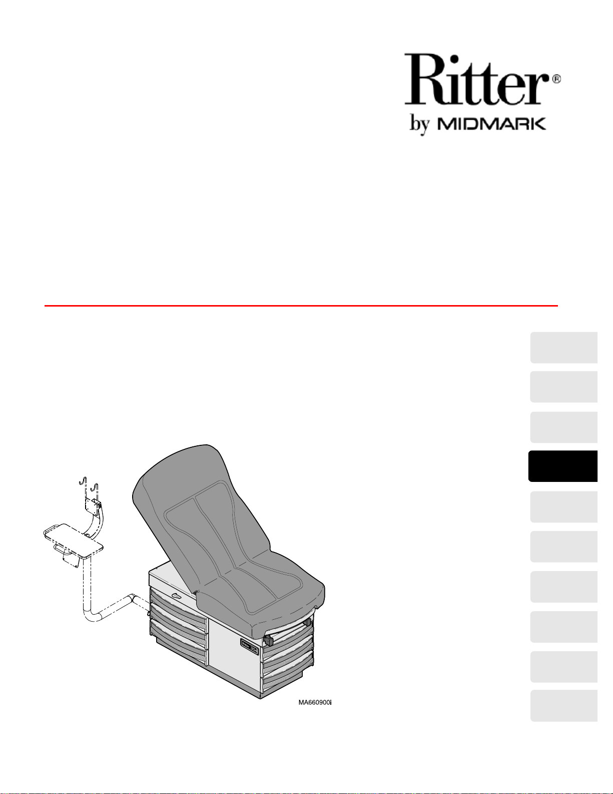
(Monitor Arm on 304-017
Integrated Patient Exam
Table [IPET] Only)
FOR USE BY MIDMARK
TRAINED TECHNICIANS ONLY
304
-001
thru
-021
SF-1532 Part No. 004-0044-00 Rev. M (03/18/08)
Page 2

Go To Table Of Contents
Page 3

TABLE OF CONTENTS
TABLE OF CONTENTS
Section/Paragraph................................................Page Section/Paragraph ............................................... Page
IMPORTANT INSTRUCTIONS
General Safety Instructions ...........................................ii
Safety Alert Symbols .....................................................ii
Warranty Instructions .................................................. ii
SECTION I GENERAL INFORMATION
1.1 Description Of 304 Exam Table.................... 1-1
1.2 Specifications ............................................... 1-3
1.3 Parts Replacement Ordering........................ 1-5
1.4 Special Tools ................................................ 1-6
SECTION II TESTING AND TROUBLESHOOTING
2.1 Operational Test (See Figure 2-1) ................ 2-1
2.2 Troubleshooting Procedures......................... 2-3
SECTION III SCHEDULED MAINTENANCE
3.1 Scheduled Maintenance ............................. 3-1
SECTION IV MAINTENANCE/SERVICE
INSTRUCTIONS
4.1 Introduction................................................... 4-1
4.2 Styled Upholstery Removal /
Installation ................................................ 4-1
4.3 Soft Touch Upholstery
Removal / Installation ............................... 4-2
4.4 Footrest Extension Removal /
Installation ................................................. 4-4
4.5 Step Assembly Removal /
Installation ................................................. 4-5
4.6 Back Lock Assembly Removal /
Installation ................................................. 4-7
4.7 Lift Lever Removal / Installation.................... 4-9
4.8 Heater ON / OFF Switch
Removal / Installation .............................. 4-11
4.9 Heater Plate Removal /
Installation ............................................... 4-12
4.10 Stirrup Components Removal /
Installation ............................................... 4-13
4.11 Electrical Receptacle Removal /
Installation (120 VAC units)..................... 4-14
4.12 Typical Electrical Receptacle Removal /
Installation (220 VAC units)..................... 4-16
4.13 Fuse Removal / Installation
(220 VAC units) ....................................... 4-18
4.14 AC Inlet Removal / Installation
(220 VAC units) ....................................... 4-19
Model 304-017 Maintenance / Service Instructions Only
4.15 Accessing Electrical Components.............. 4-20
4.16 Fuse Holders.............................................. 4-21
4.17 Transformers .............................................. 4-21
4.18 Power Strips............................................... 4-22
SECTION V SCHEMATICS AND DIAGRAMS
5.1 Electrical Schematics /
Wiring Diagrams ..................................... 5-1
SECTION VI PARTS LIST
6.1 Introduction ................................................ 6-1
6.2 Description Of Columns ............................... 6-1
6.3 Torque Specifications And Important
Assembly Notes........................................ 6-1
Pictorial Index ............................................ 6-2.*
Table Top Components
(Vacu-Form upholstery) .......................... 6-3.*
Table Top Components
(Soft Touch upholstery)............................. 6-4
Upperwrap Components ............................ 6-5.*
Stirrup Components ................................... 6-6.*
Cabinet Components
(120 VAC units) ......................................... 6-7
Cabinet Components
(220 VAC units) ......................................... 6-8
Step Assembly ............................................. 6-9
Electrical Components
(120 VAC units) ..................................... 6-10.*
Electrical Components
(220 VAC units) ..................................... 6-11.*
Receptacle Assembly
(220 VAC units) ....................................... 6-12
IPET Components...................................... 6-13
IPET Monitor Arm assembly ...................... 6-14
COMMENTS ............................................................. 7-1
FAX ORDER FORM.................................................. 7-2
(*) Indicates that there has been a serial number break for the illustration
and that there are additional point page(s) following the original page.
© Midmark Corporation 1997 SF-1532 Page i Printed in U.S.A.
Rev. 9/04
Page 4
TABLE OF CONTENTS
Return To Table Of Contents
General Safety Instructions
Safety First: The primary concern of Midmark Corporation is that this table is maintained with the safety
of the patient and staff in mind. To assure that services
and repairs are completed safely and correctly, proceed
as follows:
(1) Read this entire manual before performing any
services or repairs on this table.
(2) Be sure you understand the instructions con-
tained in this manual before attempting to service or repair this table.
Safety Alert Symbols
Throughout this manual are safety alert symbols that
call attention to particular procedures. These items are
used as follows:
DANGER
A DANGER is used for an imminently
hazardous operating procedure, practice, or condition which, if not correctly followed,
will result in loss of life or serious personal
injury.
NOTE
A NOTE is used to amplify an operating procedure,
practice or condition.
Warranty Instructions
Refer to the Midmark “Limited Warranty” printed in the
Installation and Operation Manual for warranty information. Failure to follow the guidelines listed below will
void the warranty and/or render the 304 Medical Examination Table unsafe for operation.
• In the event of a malfunction, do not attempt to use
the examination table until necessary repairs have
been made.
• Do not attempt to disassemble table, replace malfunctioning or damaged components, or perform
adjustments unless you are one of Midmark’s
authorized service technicians.
• Do not substitute parts of another manufacturer
when replacing inoperative or damaged components. Use only Midmark replacement parts.
WARNING
A WARNING is used for a potentially
hazardous operating procedure, practice, or condition which, if not correctly followed,
could result in loss of life or serious personal
injury.
CAUTION
A CAUTION is used for a potentially haz-
ardous operating procedure, practice, or
condition which, if not correctly followed, could result
in minor or moderate injury. It may also be used to
alert against unsafe practices.
EQUIPMENT ALERT
An EQUIPMENT ALERT is used for an
imminently or potentially hazardous operating procedure, practice, or condition which, if not
correctly followed, will or could result in serious, moderate, or minor damage to unit.
© Midmark Corporation 1997 SF-1532 Page ii Printed in U.S.A.
Rev. 7/04
Page 5

SECTION I
Return To Table Of Contents
GENERAL INFORMATION
SECTION I
GENERAL INFORMATION
1.1 Description Of Model 304 Medical
Examination Table
A. General Description (See Figure 1-1).
The Model 304 -001 thru -004 & -007 thru -014 Medical
Examination Table is primarily used in examination
rooms for general examinations and minor procedures.
The table top is adjustable from a full horizontal position
to a chair position. Also, when supported with an
optional pelvic lift bar, the lithotomy position can be
achieved.
Listed below are the models currently available:
304 (-001 thru -004 &
-007 thru -014)................................ 120 VAC units
304 (-018 thru -021 Canadian) .............................. N/ A
304 (-005, -006, -015, -016) .................... 220 VAC units
The components of the table are:
the drawer heater plate (optional) (1, Figure 1-1),
heater ON / OFF switch (optional), electrical receptacle,
back lock assembly, lift assembly, step assembly, and
two stirrup assemblies.
304 (-017)................................................ 120 VAC units
The Model 304 -017 Intergrated Patient Exam Table is
primarily used in examination rooms for general examinations and minor procedures.
It also provides an organized means by which a PC, and
PC-based instruments can be placed nearer to the
patient for more efficient use by the practitioner.
It has a magnetic drawer front on the side at the headend of the table. When removed, a storage area for a
PC or other electronic monitor equipment is accessible.
The monitor arm, provides support for a PC keyboard,
flat screen monitor or other similar equipment.
Two power strips, each containing six outlets, are
located on the head-end, inside the table frame, behind
the drawers. Two Isolation Transformers are located
beneath the base cover, below the drawers, on the
head-end of the table.
The 304-017 also contains the back lock and lift assemblies, stirrups, and step assembly same as the other
304 models.
It does not
exterior electrical receptacle.
contain a drawer heater and on/off switch, or
Model 304-001 thru -004 & -007 thru -014
Theory of Operation (120 VAC Units)
(See Section 5 for wiring diagram / electrical schematic)
Line voltage (120 VAC) is supplied thru the power cord
to electrical receptacles located on the side of the table.
As long as the power cord is plugged into a supply outlet, 120 VAC power will be present at the receptacles.
Models 304-018 thru -021
Has pelvic tilt options but no receptacles nor drawer
heaters.
Model 304-005, 006, -015, -016
Theory of Operation (220 VAC Units)
(See Section 5 for wiring diagram / electrical schematic)
Line voltage (220 VAC) is supplied thru the power cord
to the AC inlet located on the base of the table. From
the AC inlet, voltage is supplied to the receptacle
located on the side of the table. As long as the power
cord is plugged into a supply outlet, 220 VAC power will
be present at the receptacle.
Optional Heater Plate:
Some units are equipped with an optional heater plate
for drawer warming. When the operator turns the heater
ON / OFF switch to ON, closing the circuit, power
is supplied to the heater plate, heating the unit. This
provides heat in the top, foot end drawer to warm instruments.
Model 304-017
Theory of Operation (120 VAC Unit)
(See Section 5 for wiring diagram / electrical schematic)
Line voltage (120 VAC) is supplied thru the power cord
and four fuses to the two isolation transformers. The
transformers have 120 VAC input and output and are
used to maintain a level voltage
two power strips.
Each power strip, located on the head-end behind the
drawers, has six outlets to supply 120 VAC to accessories. The maximum load on each power strip cannot
exceed 5 amps.
(120 VAC) supply to the
© Midmark Corporation 1997 SF-1532 Page 1-1 Printed in U.S.A.
Rev. 5/05
Page 6
SECTION I
Return To Table Of Contents
GENERAL INFORMATION
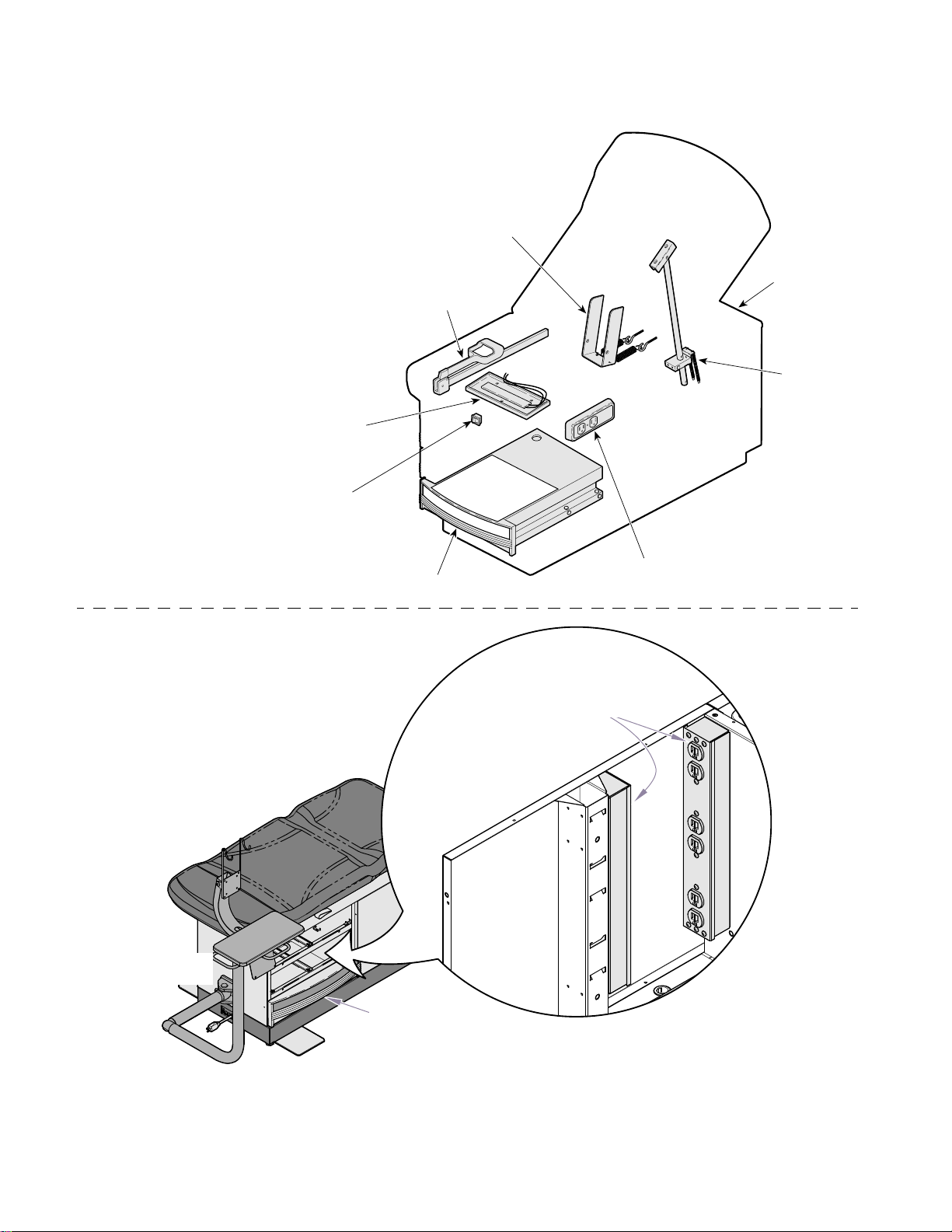
* Not Provided on Models
304-017 thru -021
Heater
On/Off
Switch
Drawer
Heater
Plate
*
Lift
Assembly
Circuit Breakers
304-018 thru -021
Stirrup
Back Lock
Assembly
*
Head
End
Monitor
Arm
304-017
Assembly
Magnetic
Drawer
Front
Step
Power
Strips (2)
Exterior
Electrical
Receptacle
MA661202i
*
MA356102i
© Midmark Corporation 1997 SF-1532 Page 1-2 Printed in U.S.A.
Rev.1/05
Figure 1-1. Major Components
Page 7
SECTION I
Return To Table Of Contents
GENERAL INFORMATION
1.2 Specifications
Table 1-2. Specifications
Description Data
Weight of a Unit (304-001 thru -004 & -007 thru -014,
& -018 thru -021):
Without Shipping Carton ................. 250 lbs (113.4 kg)
With Shipping Carton ......................... 300 lbs (136 kg)
Weight of a Unit (304-017):
Without Shipping Carton ................. 400 lbs (181.4 kg)
With Shipping Carton ...................... 450 lbs (204.1 kg)
Shipping Carton: ...60.5 in. "L" x 30 in. "W" x 42 in. "H"
(153.7 cm x 76.2 cm x 106.7 cm)
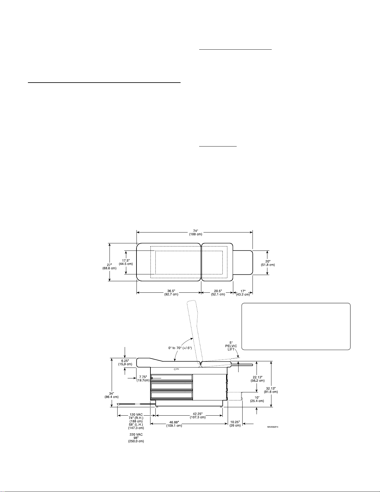
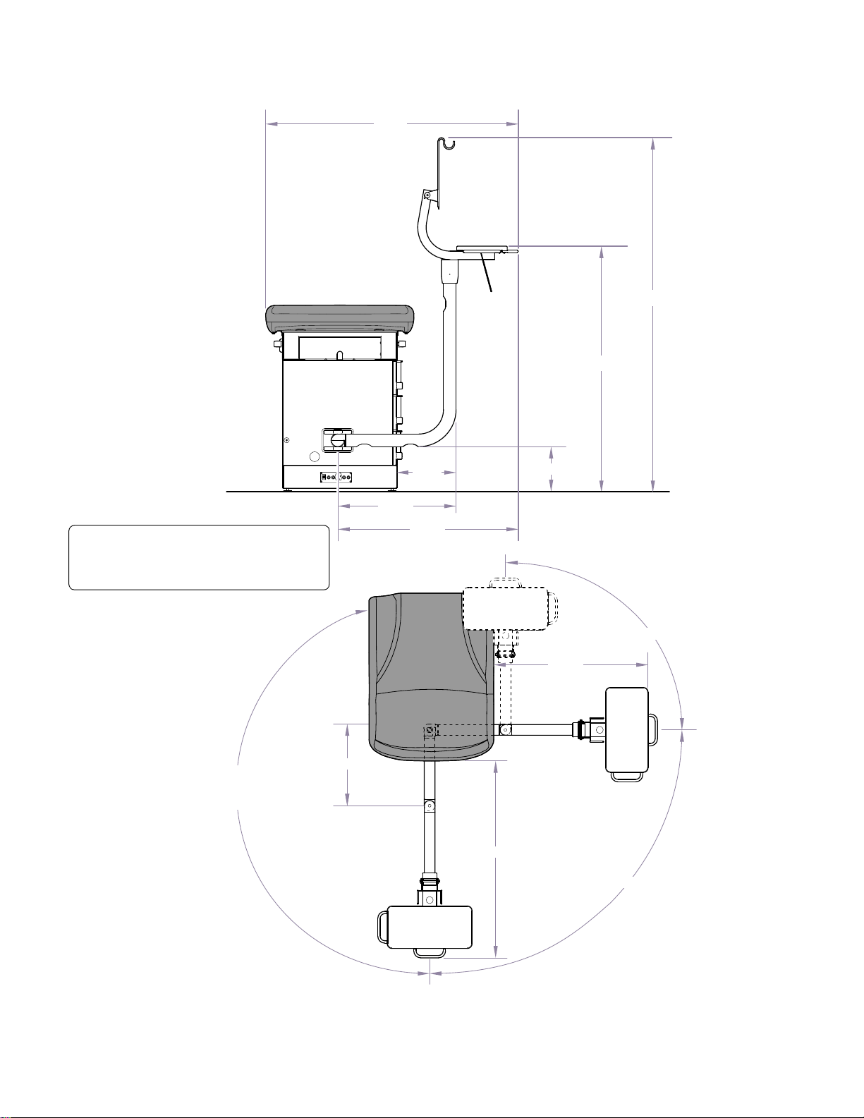
Dimensions (See Figures 1-2 & 1-3).
Weight Capacity (Maximum) ............ 325 lbs. (147.4 kg)
Electrical Requirements:
304(-001, -002, -007, -008,................... 110-120 VAC,
60 HZ, 6.0 amp, single phase
304(-003, -004, -009, -010)................... 110-120 VAC,
60 HZ, 6.5 amp, single phase
304(-005, -006, -0 15, -016)................... 220- 240 VAC,
50/60 HZ, 5 amp, single phase
304(-017) .............................................. 110-120 VAC,
60 HZ, 12.0 amp, single phase
Fuse Rating:
304(-005, -006, -015, -016)............ 6.3 amp, 250 VAC
5 x 20mm “Slo-Blo”
304 (-017) (F1, F2, F3, F4) ............ 6.3 amp, 250 VAC
5 x 20mm “Slo-Blo”
© Midmark Corporation 1997 SF-1532 Page 1-3 Printed in U.S.A.
Rev. 1/05
Figure 1-2.Dimensions
304-001 thru -010
304-015 thru -016
304-017
304-018 thru -021
*
*(See Fig. 1-3 for Monitor Arm)
Page 8
SECTION I
Return To Table Of Contents
GENERAL INFORMATION
61"
62-3/4"
55-1/4"
Head End
304-017 Monitor Arm Assembly
For Table Dimensions
refer to Figure 1-2.
Same Arm Swing
as shown on
Opposite Side
19-1/2"
27-1/2"
37-1/4"
49-1/4"
Head End
43"
7-1/2"
37-1/2"
9"x18"
90
o
90
o
© Midmark Corporation 1997 SF-1532 Page 1-4 Printed in U.S.A.
Rev. 1/05
30 lbs.
Max. Load
Figure 1-3. Dimensions
MA662201i
Page 9
SECTION I
Return To Table Of Contents
GENERAL INFORMATION
1.3 Parts Replacement Ordering
If a replacement part is required, order the part directly
from the factory as follows:
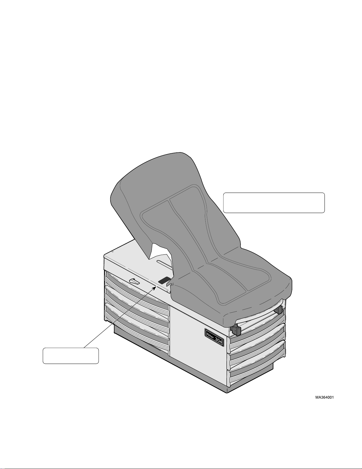
(1) Refer to Figure 1-4 to determine the location
of the model number and serial number of the
table and record this data.
(2) Refer to the Parts List to determine the item
numbers of the parts, part numbers of the
parts, descriptions of the parts, and quantities
of parts needed and record this data (Refer to
para 6.1)
NOTE
Ask the Purchasing Department of the company that
owns the table for this information. Otherwise, this
information may be obtained from the dealer that
sold the table.
(3) Determine the installation date of the table and
record this data.Call Midmark with the recorded
information and ask for the Medical Products
Technical Services Department. See back
cover of this manual for the phone number or
use the Fax Order Form (See page 7-2 for Fax
Order Form).
Model & Serial Numbers are
required when ordering parts.
MODEL NUMBER
SERIAL NUMBER
© Midmark Corporation 1997 SF-1532 Page 1-5 Printed in U.S.A.
Rev. 1/05
Figure 1-4. Model Number / Serial Number Location
Page 10
SECTION I
Return To Table Of Contents
GENERAL INFORMATION
1.4 Special Tools
the table, how to obtain the special tools, and the purpose of each special tool.
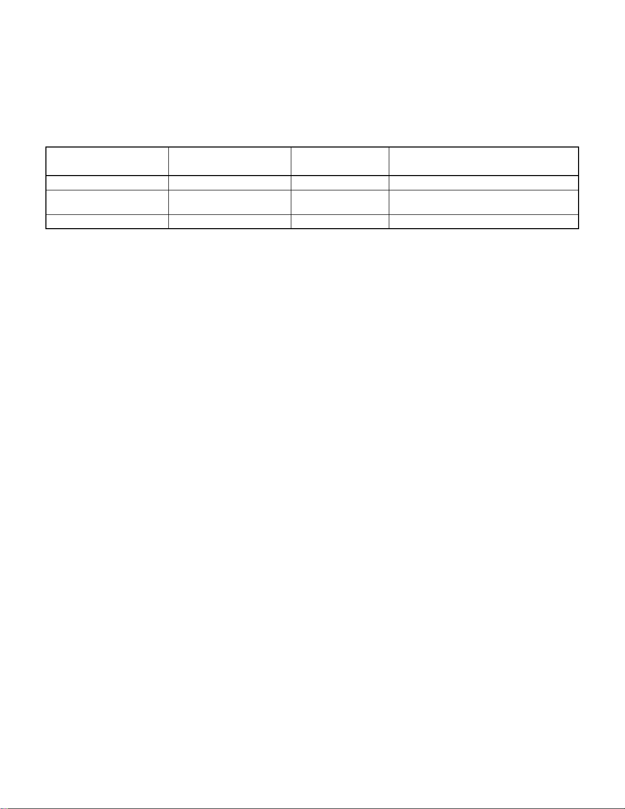
Table 1-3 lists all of the special tools needed to repair
Table 1-3. Special Tool List
Description of Special Tool
Multimeter Commercially Available Any Type Used to perform continuity and voltage checks.
Pop Rivet Gun Commercially Available For installation of 1/8 in.
Torque Wrench Commercially Available Any Type Used to tighten nuts or screws to specified values.
Manufacturer’s
Name / Address / Phone
Manufacturer’s
Part Number
pop rivets.
Purpose of Special Tool
For installation of drawer slides and mullions.
© Midmark Corporation 1997 SF-1532 Page 1-6 Printed in U.S.A.
Rev. 1/05
Page 11
TESTING AND TROUBLESHOOTING
Return To Table Of Contents
SECTION II
TESTING AND TROUBLESHOOTING
SECTION II
2.1 Operational Test (See Figure 2-1)
In order to effectively diagnose a malfunction of the
table, it may be necessary to perform an operational
test as follows:
WARNING
Refer to the Operator Manual for com-
plete instructions on operating the
examination table. Failure to do so could result
in personal injury.
NOTE
The Operational Test, for the most part, only
describes what should happen when the table is
operated. If the table does something other than
described, a problem has been discovered. Refer to
the Troubleshooting Guide to determine the cause of
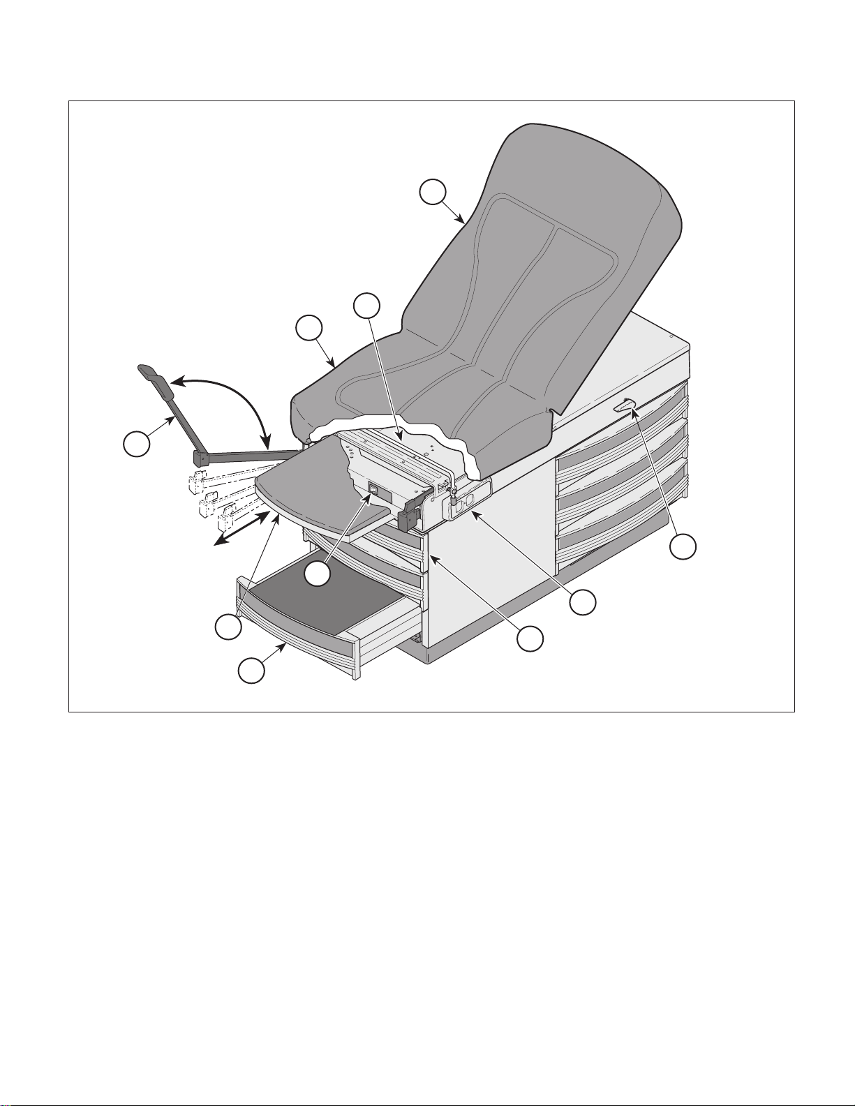
the problem and its correction.
(1) Plug the table power cord into a grounded, non-
isolated, correctly polarized outlet, that has the
proper voltage for the table.
(2) Using a multimeter, check for proper voltage at
the table’s electrical receptacle (1).
(5) Lift up on the head board assembly (4) stopping
at several positions.
Observe.
raise smoothly. The back support rod and lock
assembly should hold the head board firmly at
all positions without slipping. The head board
should be able to be raised to 80°
The head board assembly (4) should
.
NOTE
The head board assembly should hold firmly with a
200 lb. (90.7 kg) load applied to the head end of the
table.
(6) Apply pressure to the head board assembly (4)
to check for drifting. Then press down on one
of the back lock handles (5) while pressing
down on the head board assembly and lower
the head board all the way down.
Observe.
drift when pressure is applied to head board
assembly. The back lock rod assembly should
retract smoothly without binding when back lock
handles are depressed. The head board
assembly should be able to be lowered to a horizontal position.
The back lock assembly should not
Observe. For 304 (-001 thru -004 &
-007 thru -014):
present at the receptacle.
-015, -016):
at the receptacle.
(3) If the unit has the optional heater, turn the
heater ON / OFF switch (2) to ON.
Observe.
should illuminate and the heater plate should
begin to warm the top drawer at the foot end of
the table (9).
Turn the heater ON / OFF switch (2) to OFF.
(4) Pull footrest assembly (3) out all the way.
Observe.
easily. The footrest assembly should hit stops
at the end of its travel, preventing accidental
removal
.
There should be 120 VAC
For 304 (-005, -006,
There should be 220 VAC present
The heater ON / OFF switch (2)
The footrest assembly should extend
(7) On units with the optional pelvic tilt, lift up on
the seat section (6) slightly.
Observe.
matically raise up into its locked position, supporting the seat section in the pelvic lift position
(+5° above horizontal).
To lower the seat section (6) to standard position, raise up slightly on seat section; then
grasp the pelvic lift bar (7) and rotate it downward while lowering the seat section.
(8) Extend the stirrups (8); then lift up on the end of
each stirrup and move them laterally. Let the
stirrups lock into each of the four positions.
While applying downward pressure, attempt to
move each stirrup to the left and to the right.
.
The pelvic lift bar (7) should auto-
© Midmark Corporation 1997 SF-1532
Rev. 12/98
Page 2-1
Printed in U.S.A.
Page 12
SECTION II
Return To Table Of Contents
TESTING AND TROUBLESHOOTING
7
6
4
8
2
3
10
Figure 2-1. Operational Test
Observe.
easily and move freely from left to right when
raised. The stirrups should lock into each of the
four positions and should not move laterally as
long as downward pressure is applied.
(9) Check operation of each drawer (9).
The stirrups (8) should slide out
5
1
9
(10) Check operation of step (10).
Observe.
The step should drop into locked position when
it is fully extended and should not pull out of the
table.
The step (10) should pull out easily.
MA380600
Observe.
All drawer rollers should move freely in the
drawer tracks.
© Midmark Corporation 1997 SF-1532
The drawers should slide out easily.
Rev. 12/98
Page 2-2
Printed in U.S.A.
Page 13
SECTION II
Return To Table Of Contents
TESTING AND TROUBLESHOOTING
2.2 Troubleshooting Procedures
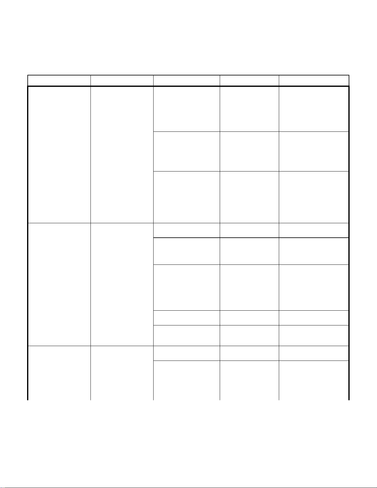
Table 2-1 is a Troubleshooting Guide which is used to
Problem Symptom Probable Cause Check Correction
Drawer warmer is not
working. Power is present
at the supply outlet.
(Not an option on 304-017)
Electrical receptacle is not
working.
(Not an option on 304-017)
Electrical receptacle or
optional drawer warmer not
working.
(Not an option on 304-017)
Heater plate assembly
does not warm up when
heater ON / OFF switch is
turned ON.
Table power cord is
plugged into wall outlet and
power is present, but there
is still no power at electrical receptacle.
No power is available at
electrical receptacle and
heater ON / OFF switch
does not illuminate when
pressed.
Heater ON / OFF switch is
malfunctioning.
Heater plate assembly is
malfunctioning
Wire connections are loose. Check all wiring connec-
Circuit Breaker(s) tripped.
(Models 304-018 thru -021)
Electrical receptacle is malfunctioning.
Wire connections are loose. Check all wiring connec-
Line fuse(s) blown (applies
to 220 VAC units only).
AC inlet is malfunctioning
(applies to 220 VAC units
only).
Power cord is not plugged
into facility wall outlet.
Facility circuit breaker providing power to table is
tripped / blown.
determine the cause of the malfunction.
When heater ON / OFF
switch is turned to ON,
heater switch should illuminate (this indicates that
there is power present at
output terminals of
switch).
Replace suspect heater
plate assembly with
known working heater
plate assembly or check
for continuity thru heater
plate assembly wires.
tions from power heater
ON / OFF switch to
heater plate assembly.
Perform continuity check
on wires. Use multimeter
to check for proper voltage levels.
Check if Circuit
Breaker(s) is tripped.
Replace suspect electrical receptacle with
known working receptacle.
tions from power cord to
electrical receptacle.
Perform continuity check
on wires. Use multimeter
to check for proper voltage levels.
Perform continuity check
on fuses.
Replace suspect AC inlet
with known working AC
inlet.
Check to see if power
cord is plugged in.
Check to see if facility circuit breaker is tripped /
blown. One way of
checking this is to plug a
lamp into wall outlet that
table was plugged into.
If heater ON / OFF switch
does not illuminate when
turned ON, replace heater
switch. Refer to para 4.8.
Replace heater plate assembly. Refer to para 4.9.
Clean any dirty connections.
Tighten any loose connections. Replace any damaged
connections. Refer to para
5.1.
Reset Circuit Breaker(s)
Replace electrical receptacle.
120 VAC Units: Refer to para
4.11. 220 VAC Units: Refer
to para 4.12.
Clean any dirty connections.
Tighten any loose connections. Replace any damaged
connections. Refer to para
5.1.
Replace fuse(s). Refer to para
4.13.
Replace AC inlet. Refer to
para 4.14.
Plug power cord into facility
wall outlet.
If circuit breaker is tripped,
determine what caused circuit
breaker to trip, correct the
problem, and then reset /
replace circuit breaker.
© Midmark Corporation 1997 SF-1532 Page 2-3 Printed in U.S.A.
Rev. 9/04
Page 14
Problem Symptom Probable Cause Check Correction
Return To Table Of Contents
Electrical receptacle or
optional drawer warmer not
working. -Continued
Head Board Assembly
does not operate correctly.
Step assembly does not
function correctly.
No power is available at
electrical receptacle and
heater ON / OFF switch
does not illuminate when
pressed. -Continued
Head Board will not stay in
position, drifts down.
Headboard will not stay in
position, drifts down
(continued).
Head Board will not
descend when back lock
handle(s) are depressed.
Head Board descends rapidly when back lock handles are depressed.
Head Board descends rapidly when back lock handles are depressed
(continued).
Step assembly difficult to
pull out.
TESTING AND TROUBLESHOOTING
Wire connections are loose. Check all wiring connec-
Line fuse(s) blown (applies
to 220 VAC units only).
AC inlet is malfunctioning
(applies to 220 VAC units
only).
Springs on back lock assembly have broken or come
loose.
The hole in the back lock
assembly for the back support rod has worn or elongated.
The back support rod has
worn excessively and will not
hold in he back lock assembly.
Back lock springs are disconnected or broken.
Back support rod out of
alignment causing the rod to
bind in the back lock assembly.
Set screws that secure the
back lock assembly to the
back lock rod are loose or
missing.
Set screw(s) are loose in the
back lock handle(s) prevent
handles from rotating back
lock rod and back lock
assembly.
Lift spring(s) are broken or
disconnected from the lift
lever or the eye bolt(s).
Lift spring(s) tension out of
adjustment.
Lift support rod for the lift
lever is disconnected.
Nylon stem bumpers worn or
missing. Lack of lubrication.
tions from power cord to
electrical receptacle and
heater ON / OFF switch.
Perform continuity check
on wires. Use multimeter
to check for proper voltage levels.
Perform continuity check
on fuses.
Replace suspect AC
inlet with known working
AC inlet.
Check condition of the
back lock springs.
Check the condition of
the back lock assembly
for excessive wear.
Check for excessive wear
on the back support rod.
Inspect the back lock
springs.
Check the alignment of
the back support rod and
insure the screws are
tight on the back support
plate or bracket.
Check the set screws to
insure they are in place
and tightened to the back
lock rod.
Check the set screws to
insure they are in place
and tightened to the back
lock rod.
Check the condition of
the lift spring(s).
Check the position of the
wing nuts to insure they
are on the eye bolts sufficiently.
Check the condition of
the lift support rod to
insure it is in place.
Check the condition of
the nylon stem bumpers.
SECTION II
Clean any dirty connections.
Tighten any loose connections. Replace any damaged
connections. Refer to para
5.1.
Replace fuse(s). Refer to para
4.13).
Replace AC inlet. Refer to
para 4.14.
Replace the springs on the
back lock assembly. Refer to
para 4.6.
Replace the back lock assembly. Refer to para 4.6.
Replace the back support
rod. Refer to para 4.6.
Connect and / or replace the
back lock springs. Refer to
para 4.6.
Re-align the back support rod
plate or bracket and tighten
the mounting screws. Refer to
para 4.6.
Install and / or tighten the set
screws in the back lock
assembly. Refer to para 4.6.
Install and / or tighten the set
screws in the back lock handles. Refer to para 4.6.
Reconnect or replace the lift
springs. Refer to para 4.7.
Adjust the spring tension on
the lift springs. Refer to para
4.7.
Repair or replace the lift support rod. Refer to para 4.7.
Replace and lubricate the
nylon stem bumpers. Refer to
para 4.5.
© Midmark Corporation 1997 SF-1532
Rev. 12/98
Page 2-4
Printed in U.S.A.
Page 15
Problem Symptom Probable Cause Check Correction
Return To Table Of Contents
Step assembly does not
function correctly.
-Continued
Step assembly pulls completely out of table when
fully extended.
TESTING AND TROUBLESHOOTING
Step stop missing or out of
alignment.
Check the condition of
the step stop.
SECTION II
Repair or replace the step
stop. Refer to para 4.5.
Drawer(s) do not function
correctly.
Pelvic tilt does not function
correctly.
Footrest assembly does
not function correctly.
Stirrups do not work correctly.
Step will not lock into position when fully extended.
Drawer(s) difficult to slide
in and out of the table.
Pelvic tilt lift bar does not
spring to “Up” position
when the seat section is
lifted.
Footrest does not extend
or retract smoothly.
Footrest pulls all the way
out when fully extended.
Stirrups do not lock into
one of four lateral positions.
Lock tabs on bottom rails of
step weldment are not bent
down far enough.
Drawer(s) not located properly in the cabinet slides.
Drawer and / or cabinet slide
is damaged.
Ball bearings in cabinet
slides dry of lubricant or contaminated with foreign
debris.
Pivot points on pelvic lift bar
dry of lubricant and / or dirty.
Springs on the pelvic tilt bar
are broken.
Push nuts that retain pelvic
lift bar on tabs of upper weldment rubbing on bar.
The nylo tape in the footrest
cabinet guides is missing or
dry of lubricant.
The footrest weldment is
bent or damaged.
The “stop” tabs at the back
of the footrest weldment are
not bent down correctly.
Stirrups dirty and lacking
lubricant.
Check if lock tabs on bottom rails of step weldment are bent down.
Check to insure the
drawer slide is located
properly in the cabinet
slide.
Check the condition of
the slides on the
drawer(s) and cabinet.
Check the ball bearings
and cabinet slides.
Check the condition of
the pivot points on the
pelvic lift bar.
Check the condition of
the springs on the pelvic
tilt bar.
Check the position of the
push nuts in relation to
the pelvic lift bar.
Check the condition of
the nylo tape.
Inspect the footrest weldment to insure it is
straight.
Inspect the footrest weldment to insure the tabs
are bent down and that
the rubber bumpers are
in place on the footrest
cabinet guides.
Inspect the stirrup
assemblies for dirt and
lack of lubricant.
Bend the lock tabs down
approximately 1/8 inch (0.32
cm) from the bottom of the
step weldment rails. Refer to
para 4.5.
Insert the drawer slide properly in the cabinet slide.
Replace the cabinet slide(s)
and / or drawer assemblies.
Clean, lubricate or replace the
cabinet slide(s).
Clean and lubricate the pivot
points on the pelvic lift bar.
Replace the springs on the
pelvic tilt bar.
Repair or replace the push
nuts.
Lubricate and / or replace the
nylon tape in the cabinet
guides. Refer to para 4.4.
Replace the footrest weldment. Refer to para 4.4.
Repair or replace the footrest. Refer to para 4.4.
Clean and lubricate the stirrup assemblies.
© Midmark Corporation 1997 SF-1532
Rev. 12/98
Page 2-5
Printed in U.S.A.
Page 16

SECTION II
Return To Table Of Contents
TESTING AND TROUBLESHOOTING
© Midmark Corporation 1997 SF-1532
Rev. 12/98
Page 2-6
Printed in U.S.A.
Page 17
SCHEDULED MAINTENANCE
Return To Table Of Contents
SECTION III
SCHEDULED MAINTENANCE
SECTION III
3.1 Scheduled Maintenance
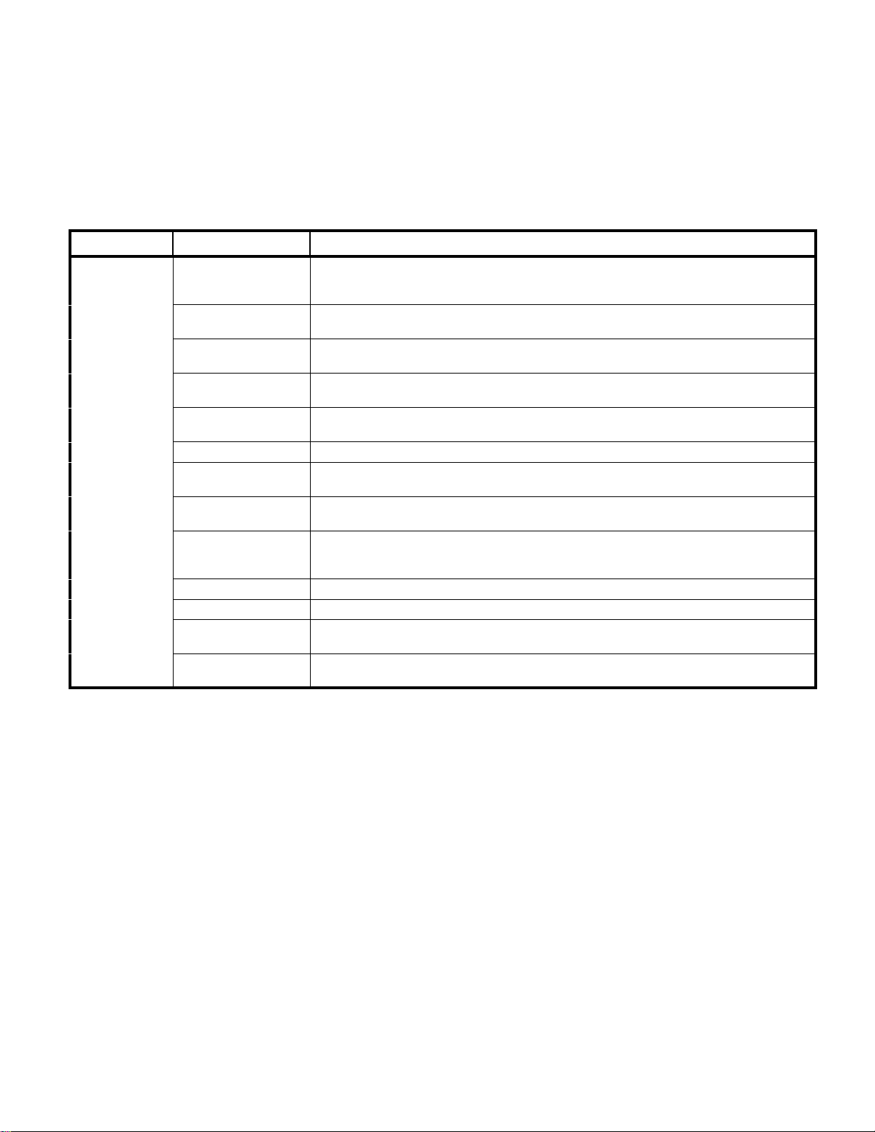
periodically on the 304 Examination Table. These
inspections and services should be performed as often
Table 3-1 is a Scheduled Maintenance Chart which lists
as indicated in the chart.
the inspections and services that should be performed
Interval Inspection or Service What to Do
Semi-annually Obvious damage Visually check condition of table for obvious damage such as: cracks in components, missing com-
Fasteners / hardware Check table for missing or loose fasteners / hardware. Replace any missing hardware and tighten
Warning and instructional
decals
Pivot points / moving
parts / accessories
Step Assembly Check step assembly to insure that it slides in and out easily. Insure that the step assembly locks in
Footrest extension Check that footrest extension can be easily extended and is not damaged. Refer to para 4.3.
Stirrup assemblies Check that stirrup assemblies lock into one of four different positions. Check for wear. Replace
Electrical receptacle Check that the electrical receptacle are functioning properly. Replace receptacle as necessary.
Drawer Heater (Optional) Where applicable, check to insure the drawer heater is heating sufficiently to warm the top drawer
Pelvic Tilt (Optional) Check that the spring loaded pelvic tilt is operating properly. Replace springs if necessary.
Upholstery Check all upholstery for rips, tears, or excessive wear. Replace cushions as necessary.
Accessories Check that all accessories have all of their components and that they function properly. If neces-
Operational Test Perform an Operational Test to determine if the table is operating within its specifications (Refer to
ponents, dents in components, or any other visible damage which would cause the table to be
unsafe to operate or would compromise its performance. Repair table as necessary.
any loose hardware as necessary.
Check for missing or illegible decals. Replace decals as necessary.
Lubricate all exposed pivot points, moving parts, and accessories with silicone based lubricant.
place when extended. Refer to para 4.4.
worn components as necessary. Refer to para 4.14.
Refer to para 4.9.
and that the heater ON / OFF switch indicator light illuminates when the switch is in the ON position. If necessary, replace the heater switch or heater plate. Refer to para 4.7 or 4.8.
sary, repair or replace the accessory.
para 2.1). Replace or adjust any malfunctioning components.
© Midmark Corporation 1997 SF-1532
Page 3-1
Printed in U.S.A.
Page 18

SECTION III
Return To Table Of Contents
SCHEDULED MAINTENANCE
© Midmark Corporation 1997 SF-1532
Page 3-2
Printed in U.S.A.
Page 19
MAINTENANCE / SERVICE
Return To Table Of Contents
SECTION IV
MAINTENANCE / SERVICE INSTRUCTIONS
SECTION IV
4.1 Introduction
WARNING
Refer to the Operator Manual for com-
plete instructions on operating the
examination table. Failure to do so could result
in personal injury.
NOTE
Perform an operational test on the examination table
after the repair is completed to confirm the repair was
properly made and that all malfunctions were
repaired.
4.2 Styled Upholstery
A. Removal
WARNING
Always disconnect electrical power to
the unit before removing any of the
unit's covers/shrouds or making any repairs to
prevent the possibility of electrical shock. Failure
to comply could result in personal injury.
(5) Remove the upholstered top assembly (6).
(6) Extend the footrest and remove the upholstered
footrest pad (7).
B. Installation
CAUTION
Use care when installing the upholstered
top assembly as it weighs approximately
32 lbs. (14.5 kg). Failure to use proper lifting techniques or assistance could result in personal injury.
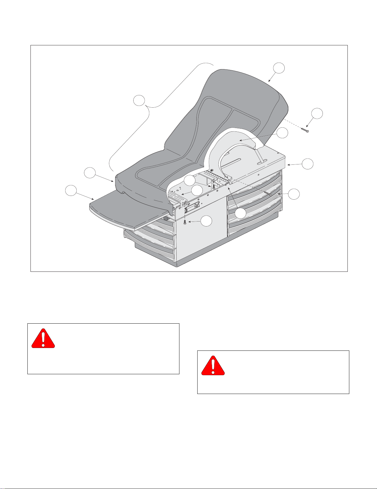
(1) Lay the new upholstery assembly (6, Figure
4-1) in position on the back plate assembly (5)
and upper wrap assembly (8).
(2) Secure the head section (C) to the back plate
assembly (5) with four screws (4).
(3) Secure the seat section (A) to the top hinge (3)
with two screws (2).
(4) For tables without Pelvic Tilt, install the two
screws (1) that secure the seat section (A) to
the upper wrap cross member (B).
(1) Unplug the table power cord from the wall out-
let.
(2) For tables without Pelvic Tilt, remove the two
screws (1, Figure 4-1) that secure the seat section (A) to the upper wrap cross member (B).
(3) Remove the two screws (2) that secure the
upholstered seat section (A) to the top
hinge (3).
(4) Elevate and support the head section (C) and
remove the four screws (4) that secure the
upholstered head section (C) to the back plate
assembly (5).
CAUTION
Use care when removing the upholstered
top assembly as it weighs approximately
32 lbs. (14.5 kg). Failure to use proper lifting techniques or assistance could result in personal injury.
(5) Raise and lower the head section (C) several
times to insure it operates smoothly and locks
in position without drifting. If necessary, refer to
Testing and Troubleshooting, para 2.1.
(6) Install the upholstered footrest pad (7).
(7) Plug the table power cord into a wall outlet.
© Midmark Corporation 1997 SF-1532 Page 4-1 Printed in U.S.A.
Rev. 7/04
Page 20
SECTION IV
Return To Table Of Contents
MAINTENANCE / SERVICE
A
7
C
6
4
5
8
2
B
4
Figure 4-1. Styled Upholstery
4.3 Soft Touch Upholstery
A. Removal
WARNING
Always disconnect electrical power to
the unit before removing any of the
unit's covers/shrouds or making any repairs to
prevent the possibility of electrical shock. Failure
to comply could result in personal injury.
(1) Unplug the table power cord from the wall
outlet.
3
1
MA376600
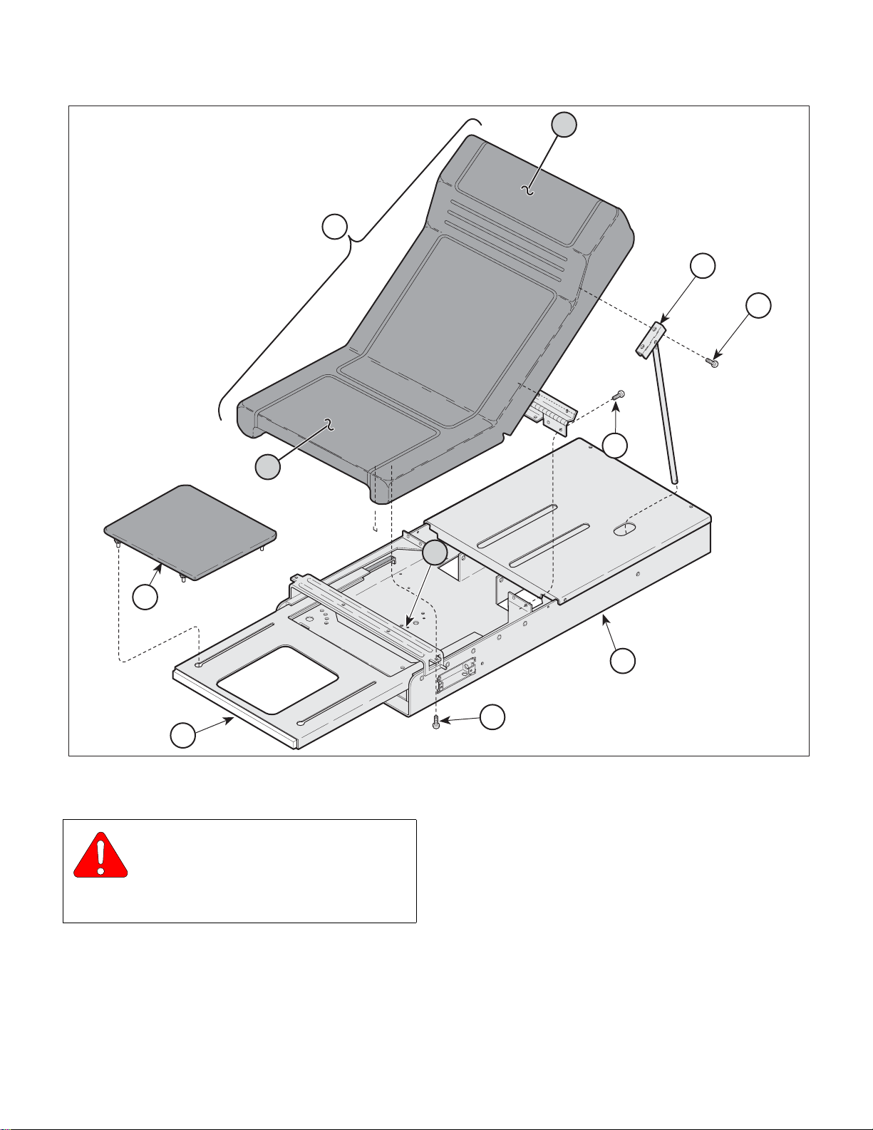
(3) Elevate and support the head section (C) and
remove the two screws (2) securing the rod
support bracket (3) to the head section (C).
(4) Lay the head section (C) forward and remove
four screws (4) securing the upholstered top
assembly (5) to upper wrap (6).
CAUTION
Use care when removing the upholstered
top assembly as it weighs approximately
32 lbs. (14.5 kg). Failure to use proper lifting techniques or assistance could result in personal injury.
(2) For tables without Pelvic Tilt, remove the two
screws (1, Figure 4-2) that secure the seat section (A) to the upper wrap cross member (B).
© Midmark Corporation 1997 SF-1532 Page 4-2 Printed in U.S.A.
Rev. 7/04
(5) Remove the upholstered top assembly (5).
(6) Extend the footrest shelf (7) and remove the
upholstered footrest pad (8).
Page 21
A
Return To Table Of Contents
SECTION IV
MAINTENANCE / SERVICE
C
5
3
2
4
8
7
Figure 4-2. Soft Touch Upholstery
B. Installation
CAUTION
Use care when installing the upholstered
top assembly as it weighs approximately
32 lbs. (14.5 kg). Failure to use proper lifting techniques or assistance could result in personal injury.
(1) Lay the new upholstery assembly (5,
Figure 4-2) in position on the upper wrap
assembly (6) and secure with four screws (4).
B
6
1
MA485200
(2) Lay the head section (C) backward slightly and
secure to rod support bracket (3) with two
screws (2).
(3) For tables without Pelvic Tilt, install the two
screws (1) that secure the seat section (A) to
the upper wrap cross member (B).
(4) Raise and lower the head section (C) several
times to insure it operates smoothly and locks
in position without drifting. If necessary, refer to
Testing and Troubleshooting, para 2.1.
© Midmark Corporation 1997 SF-1532 Page 4-3 Printed in U.S.A.
Rev. 7/04
Page 22
SECTION IV
Return To Table Of Contents
MAINTENANCE / SERVICE
(5) Install the upholstered footrest pad (8) on foot
rest shelf (7).
(6) Plug the table power cord into a wall outlet
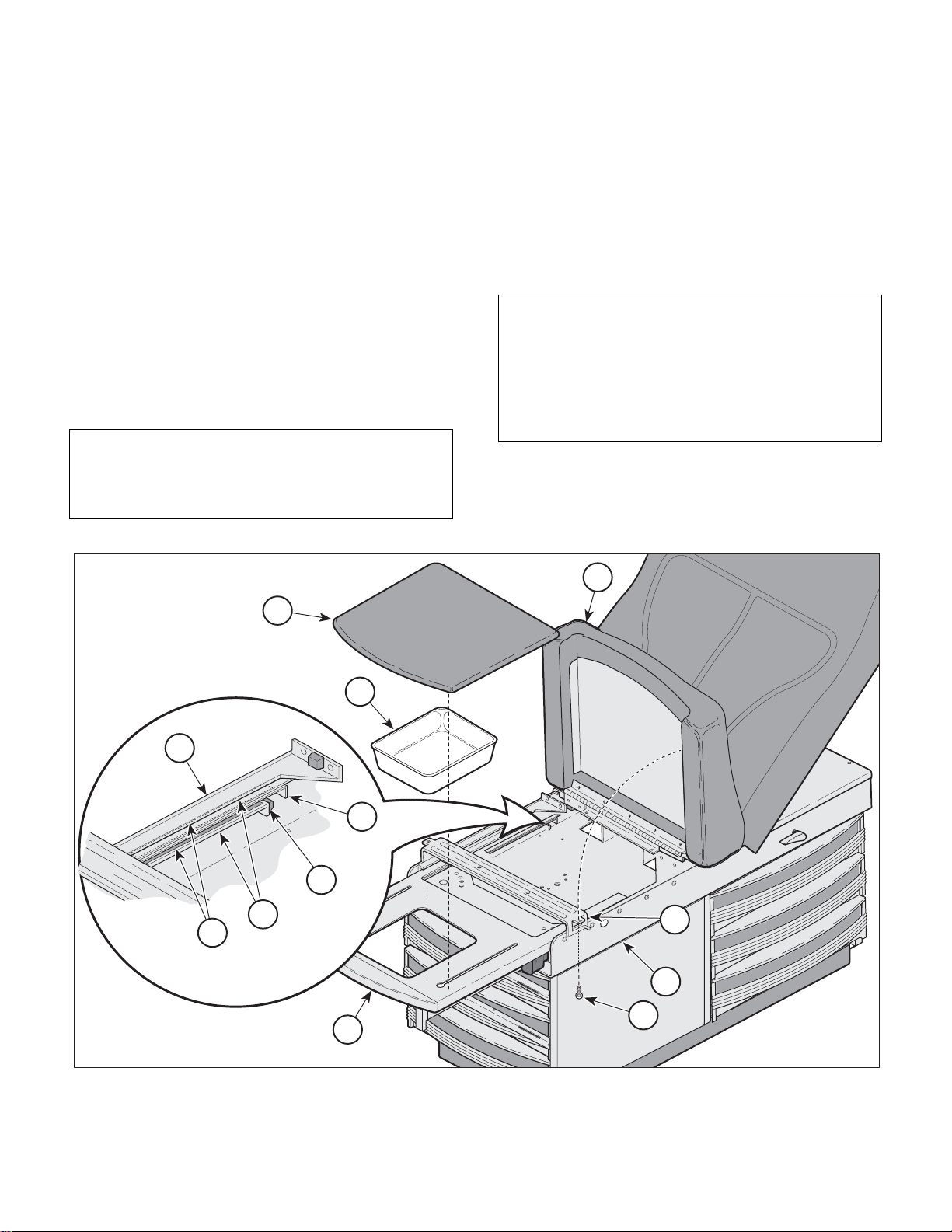
4.4 Footrest Extension
A. Removal
(1) Unplug table power cord from the wall outlet.
(2) Pull out the on the footrest (1, Figure 4-3) until it
is fully extended.
(3) Remove the upholstered footrest pad (2) and
treatment pan (3).
NOTE
For tables without Pelvic Tilt, remove the two screws
(4) that secure the seat section (5) to the upper wrap
cross member (A).
(4) Raise the seat section (5) and using pliers or
equivalent, bend up the two metal tabs (6) on
the back of the footrest weldment (1) until they
are horizontal.
(5) Pull the footrest weldment (1) out of the upper
wrap weldment (7).
B. Installation
NOTE
Before installing the footrest weldment, inspect the
footrest runners (B, Figure 4-3) to insure the nylon
tape glides (8) are in place at the side and top of
each runner. Also inspect the rubber bumpers (9),
located at the back of the footrest runners to insure
they are intact.
(1) Inspect the nylon tape glides (8, Figure 4-3) and
rubber bumpers (9) and replace if necessary.
Place a light coating of lubricant on the glides.
5
2
3
7
6
9
B
A
8
7
4
1
© Midmark Corporation 1997 SF-1532 Page 4-4 Printed in U.S.A.
Rev. 7/04
MA364300
Figure 4-3. Footrest Extension
Page 23
(2) Insert the footrest weldment (1) into the runners
A
A
Return To Table Of Contents
(B) of the upper wrap weldment (7) and bend
the two metal tabs (6) on the footrest weldment
downward until vertical.
(3) Install the treatment pan (3) and upholstered
footrest pad (2).
(4) Plug the table power cord into wall outlet.
4.5 Step Assembly
A. Removal
WARNING
Always disconnect electrical power to
the unit before removing any of the
unit's covers/shrouds or making any repairs to
prevent the possibility of electrical shock. Failure
to comply could result in personal injury.
(1) Unplug the table power cord from the wall out-
let.
SECTION IV
MAINTENANCE / SERVICE
1
1
5
5
6
6
7
7
3
3
4
4
8
8
2
2
9
9
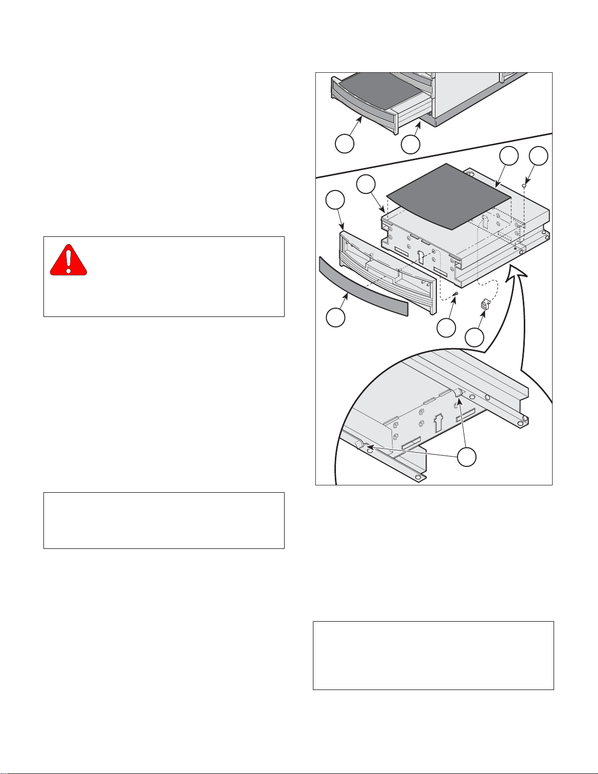
(2) Pull out on the step assembly (1, Figure 4-4)
until it is fully extended.
(3) While lightly pulling the step assembly outward,
reach beneath it and push the step stop (2)
upward until it clears the base weldment (3);
then remove the step assembly from the
cabinet.
B. Drawer Front Replacement
NOTE
Should it be necessary to replace the plastic step
front on the step assembly, the step covering must
also be replaced as it is adhered to the step front.
(1) Remove the step covering (4, Figure 4-4) from
the step assembly (5).
(2) Reaching up through the opening at the bottom
of the drawer front (6), push out on the insert
panel (7) and remove it.
(3) Remove the eight screws (8) that secure the
drawer front (6) to the step weldment (5) and
remove the drawer front.
MA356500
Figure 4-4. Step Assembly
(4) Clean the surface of the step weldment (5), to
which the step covering (4) will be attached,
with alcohol or a similar cleanser to insure the
adhesive back will bond to the surface of the
step weldment.
(5) Install the drawer front (6) to the step weld-
ment (5) and secure with eight screws (8).
NOTE
Before removing the protective cover from the adhesive backing of the step., lay the cover in place and
make some light location marks to insure the step
cover is installed uniformly on the step weldment.
Rev. 7/04
© Midmark Corporation 1997 SF-1532 Page 4-5 Printed in U.S.A.
Page 24
SECTION IV
Return To Table Of Contents
MAINTENANCE / SERVICE
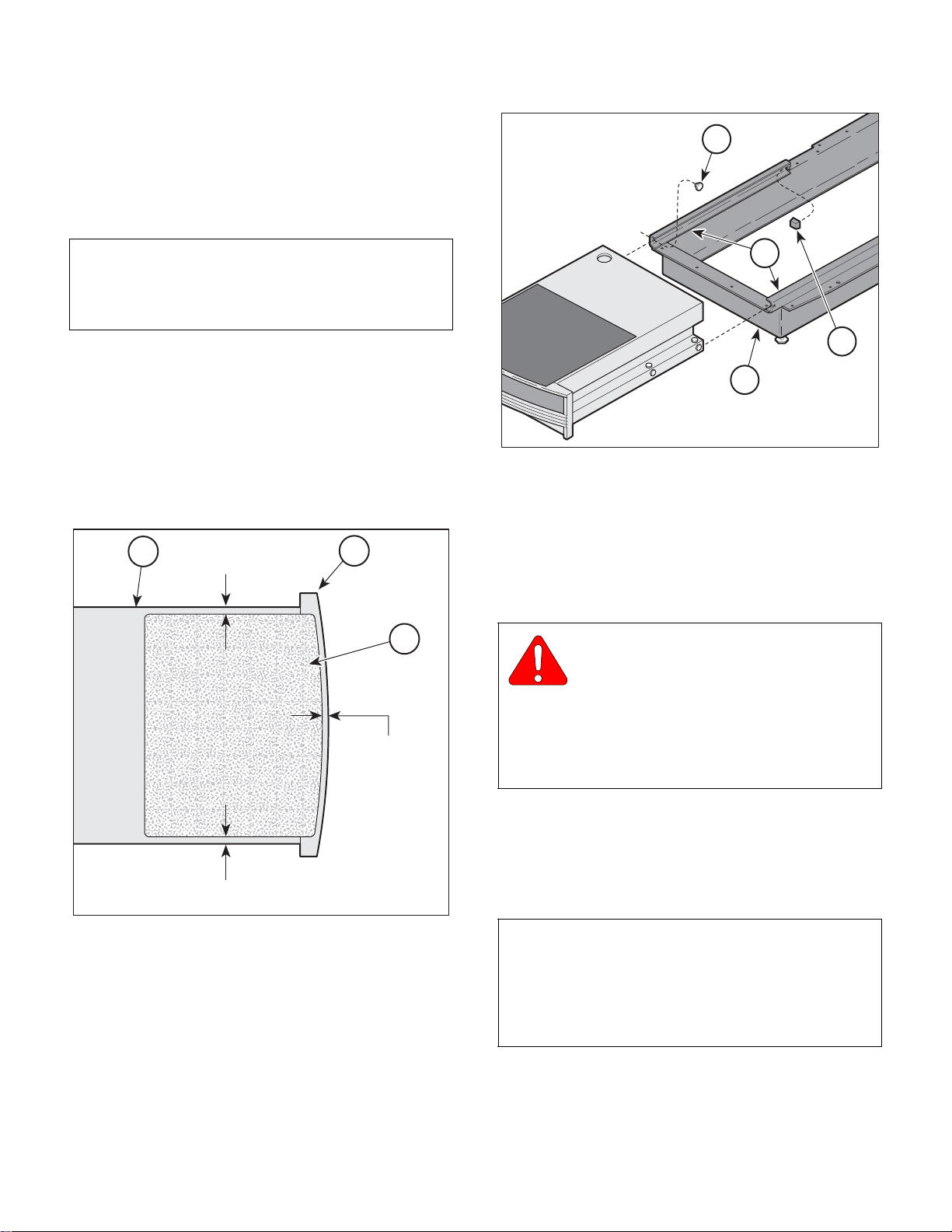
(6) Before installing the step cover (1, Figure 4-5)
lay it on the step weldment (2) and make location marks. The step cover (1) should be
located so that it is positioned approximately
5/16 inch (0.794 cm) from the outer edges of
the drawer front (3) and step weldment (2).
NOTE
Using alcohol or equivalent, clean any residue off the
surface of the step before installing the new step
cover.
(7) Remove the protective cover from the step
cover (4, Figure 4-4) and place it in position,
aligned with the location marks.
1
1
A
A
2
2
3
3
(8) Inspect the nylon stem bumpers (9) on the step
weldment (5) and replace if necessary.
2
5/16" to 3/8"
(.8 cm to .9 cm)
3
1
5/16" to 3/8"
(.8 cm to .9 cm)
5/16" to 3/8"
(.8 cm to .9 cm)
Figure 4-5. Drawer Front Replacement
MA356600
MA356700
MA356700
Figure 4-6. Nylon Bumper Replacement
(9) Inspect the nylon stem bumpers (1, Figure 4-6)
and bumper stops (2) on the runners (A) of the
base weldment (3) and replace if worn.
C. Installation
EQUIPMENT ALERT
Before installing the step assembly into the
cabinet check that the lock tabs (A, Figure
4-4) on both sides of the bottom of step weldment (5)
are bent downward approximately 1/8 inch (0.318
cm) but no farther than the surface of nylon stem
bumpers (9) next to tabs. These tabs (A) lock the
step assembly in position when it is extended.
(1) Inspect the lock tabs (A, Figure 4-4) and adjust
if necessary.
(2) Place some lubricant, such as vaseline, on the
nylon stem bumpers (9).
NOTE
When inserting step assembly into the cabinet, the
step will have to be lifted slightly to clear the lock tabs
at the bottom of the step assembly. It will also be
necessary to push up on the step stop (2, Figure 4-4)
in order for the stop to clear the base weldment.
© Midmark Corporation 1997 SF-1532 Page 4-6 Printed in U.S.A.
Rev. 7/04
Page 25
SECTION IV
Return To Table Of Contents
MAINTENANCE / SERVICE
(3) Install the step assembly (1) into the cabinet.
CAUTION
Extend the step assembly outward to
insure it locks into place. If necessary,
readjust the lock tabs (A, Figure 4-4). Failure to
insure the step assembly locks into place could
cause injury to the user.
(4) Plug the table power cord into the wall outlet.
4.6 Back Lock Assembly
A. Removal
WARNING
Always disconnect electrical power to
the unit before removing any of the
unit's covers/shrouds or making any repairs to
prevent the possibility of electrical shock. Failure
to comply could result in personal injury.
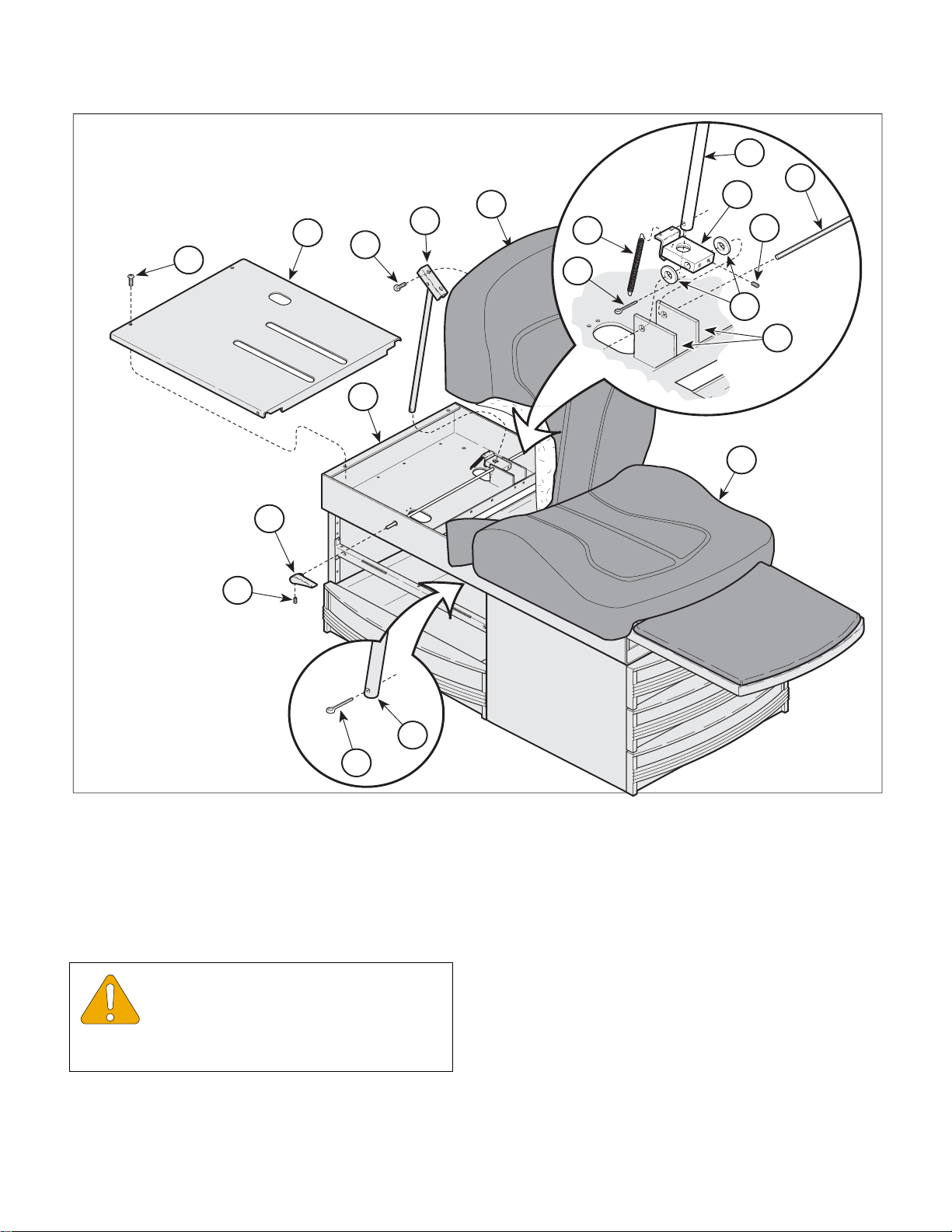
(1) Unplug table power cord from the wall outlet.
(2) Remove the two top drawers from the side of
the cabinet to gain access to the bottom of the
back support rod (1, Figure 4-7).
(3) Remove the cotter pin (2) from the back sup-
port rod (1).
NOTE
To prevent the back lock assembly (3) from snapping
back against the upper wrap weldment (4) when the
back support rod (1) is removed, slightly depress one
of the back lock handles (5) while removing the back
support rod (1). When the back support rod (1) is
clear of the back lock assembly (3), slowly release
the handle (5).
(4) Elevate the head board assembly (6) until the
back support rod (1) is clear of the upper wrap
cover (7). Allow the head board (6) to rest
against the seat section (8).
(5) Remove the four screws (9) that secure the
upper wrap cover (7) to the upper wrap assembly (4) and remove the upper wrap cover.
(7) Loosen the set screw (11) and remove the back
lock handle (5).
(8) Loosen the two set screws (12) that secure the
back lock rod (13) to the bracket (A) of the
upper wrap assembly (4).
(9) Pull the back lock rod (13) out of the back lock
assembly (3), two washers (14) and the bracket
(A) of the upper wrap assembly (4).
(10) Remove the back lock assembly (3) and two
washers (14) from the bracket (A) of the upper
wrap assembly (4).
B. Installation
(1) Insert the back lock rod (13, Figure 4-7) thru the
bracket (A) of the upper wrap assembly, two
washers (14) and back lock assembly (3).
EQUIPMENT ALERT
Do not over-tighten the set screws in
the back lock handles. Torque to 10 to
20 inch / lbs. (1.13 to 2.26 N•M).
(2) Install the back lock handle (5) onto the back
lock rod (13) aligning it with the other back lock
handle (5) and tighten the set screw (11) to 10
to 20 inch / lbs. (1.13 to 2.26 N•M).
(3) Connect the two back lock springs (10) to the
upper wrap (4) and compress the spring hooks
to secure the springs to the upper wrap assembly.
CAUTION
Use care to prevent the head board from
falling when inserting the back support rod
into the back lock assembly. Failure to do may cause
personal injury.
(4) Lifting the back lock assembly (3), align the
back support rod (1) with the hole in the back
lock assembly and insert the rod thru the
assembly.
(6) Disconnect the back lock spring (10) from the
upper wrap assembly (4).
© Midmark Corporation 1997 SF-1532 Page 4-7 Printed in U.S.A.
Rev. 7/04
Page 26
SECTION IV
14
12
1
3
10
A
13
2
Return To Table Of Contents
MAINTENANCE / SERVICE
7
9
6
1
15
4
8
5
11
(5) With the head board (6) in the elevated or chair
position, rotate the back lock handles (5) so the
pointed end of the handles are facing toward
the foot-end of the table and the handles are
pointed downward approximately 15° to 20°.
EQUIPMENT ALERT
Use care not to over-tighten the set screws
in the
back lock assembly. Tighten the set screws 75 to
80 in. / lbs.(0.533 to 0.604 N•M).
1
2
MA364400
Figure 4-7. Back Lock Assembly
(6) Tighten one of the set screws (12) on the back
lock assembly (3) to secure the back lock
assembly to the back lock rod (13).
(7) Lower the head board (6) to the horizontal posi-
tion and observe the position of the back lock
handles (5). The handles should be parallel
with the bottom edge of the head board or
pointed slightly downward.
(8) If necessary, lift the head board, loosen the set
screw on the back lock assembly and rotate the
handles up or down to adjust their position.
Lower the head board and check the positions.
© Midmark Corporation 1997 SF-1532 Page 4-8 Printed in U.S.A.
Rev. 7/04
Page 27
SECTION IV
Return To Table Of Contents
MAINTENANCE / SERVICE
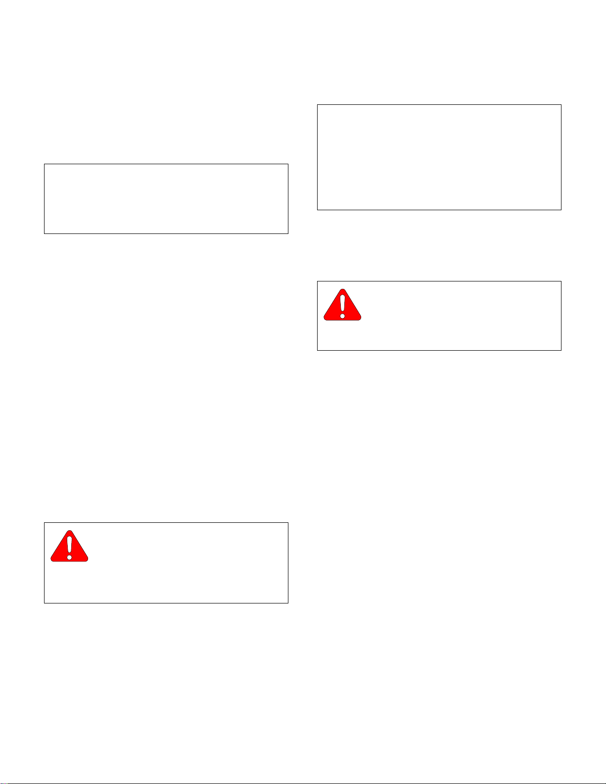
(9) Raise the head board (6) and tighten both set
screws (12) on the back lock assembly to 75 to
80 in. / lbs. (0.533 to 0.604 N•M).
(10) Raise and lower the head board (6) several
times to insure the back support rod (1) moves
up and down smoothly without binding.
NOTE
If the back support rod (1) binds, loosen the two set
screws on the back support rod (1). Raise and lower
the head board (6) several times until it operates
smoothly and retighten the screws on the bracket.
(11) Raise the head board (6) until the back support
rod (1) is free from the back lock assembly (3).
(12) Supporting the head board (6), install the cover
assembly (7) and secure with four screws (9).
(13) Rotate the back lock handles (5) to align the
hole in the back lock assembly (3) and insert
the back support rod (1).
(3) Remove the cotter pin (2) from the back support
rod (1).
NOTE
To prevent the back lock assembly (3) from snapping
back against the upper wrap weldment (4) when the
back support rod (1) is removed, slightly depress one
of the back lock handles (5) while removing the back
support rod (1). When the back support rod (1) is
clear of the back lock assembly (3) slowly release the
handle (5).
(4) Elevate the head board assembly (6) until the
back support rod (1) is clear of the upper wrap
cover assembly (7). Allow the head board (6) to
rest against the seat section (8).
CAUTION
Insure the head board is positioned and
secured to prevent it from falling while
working on the table. Failure to do so could result in
personal injury.
(14) Insert the cotter pin (2) in the end of the back
support rod (1) and bend over the ends of the
cotter pin.
(15) Lightly lubricate the back support rod (1), check
operation and install the drawers.
(16) Plug the table power cord into wall outlet.
4.7 Lift Lever Removal / Installation
A. Removal
WARNING
Always disconnect electrical power to
the unit before removing any of the
unit's covers/shrouds or making any repairs to
prevent the possibility of electrical shock. Failure
to comply could result in personal injury.
(1) Unplug the table power cord from the wall out-
let.
(2) Remove the two top drawers from the side of
the cabinet to gain access to the bottom of the
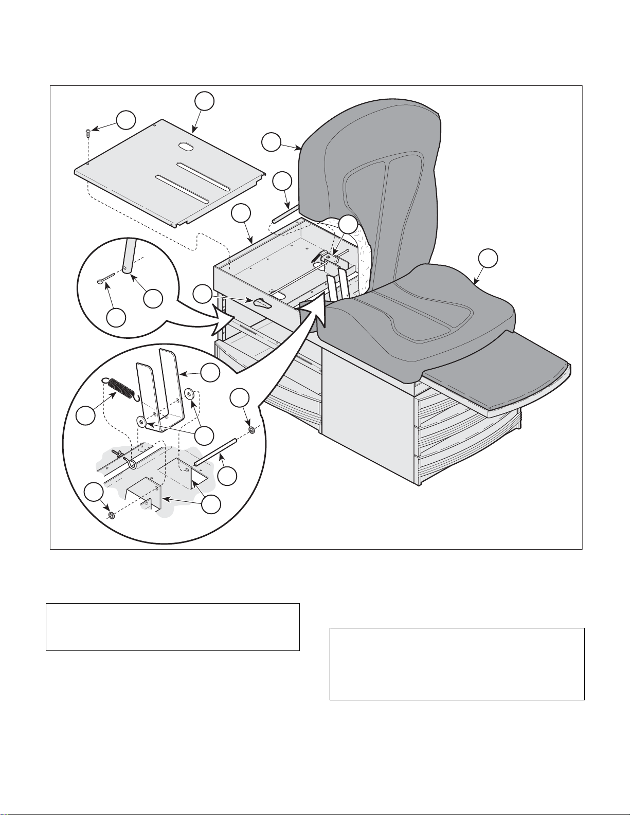
back support rod (1, Figure 4-8).
(5) Remove the four screws (9) that secure the
upper wrap cover (7) to the upper wrap assembly (4) and remove the upper wrap cover.
(6) Disconnect the lift springs (10) from the lift
lever (11).
(7) Remove the push-on retaining ring (12) from
one side of the lift support rod (13) and remove
the rod (13) and washers (14) from the lift
lever (11) and upper wrap assembly (4).
B. Installation
(1) Place lift lever (11, Figure 4-8) and two flat
washers (14) in position on the brackets (A) of
the upper wrap assembly (4).
(2) Insert the lift support rod (13) thru the
brackets (A) on the upper wrap assembly and
lift lever (11).
(3) Insure the lift support rod (13) is centered in the
bracket (A) and install the push-on retaining
rings (12).
© Midmark Corporation 1997 SF-1532 Page 4-9 Printed in U.S.A.
Rev. 7/04
Page 28
SECTION IV
2
1
12
13
A
12
14
11
10
Return To Table Of Contents
MAINTENANCE / SERVICE
7
9
5
6
1
4
3
8
(4) Connect the lift springs (10) to the lift lever (11).
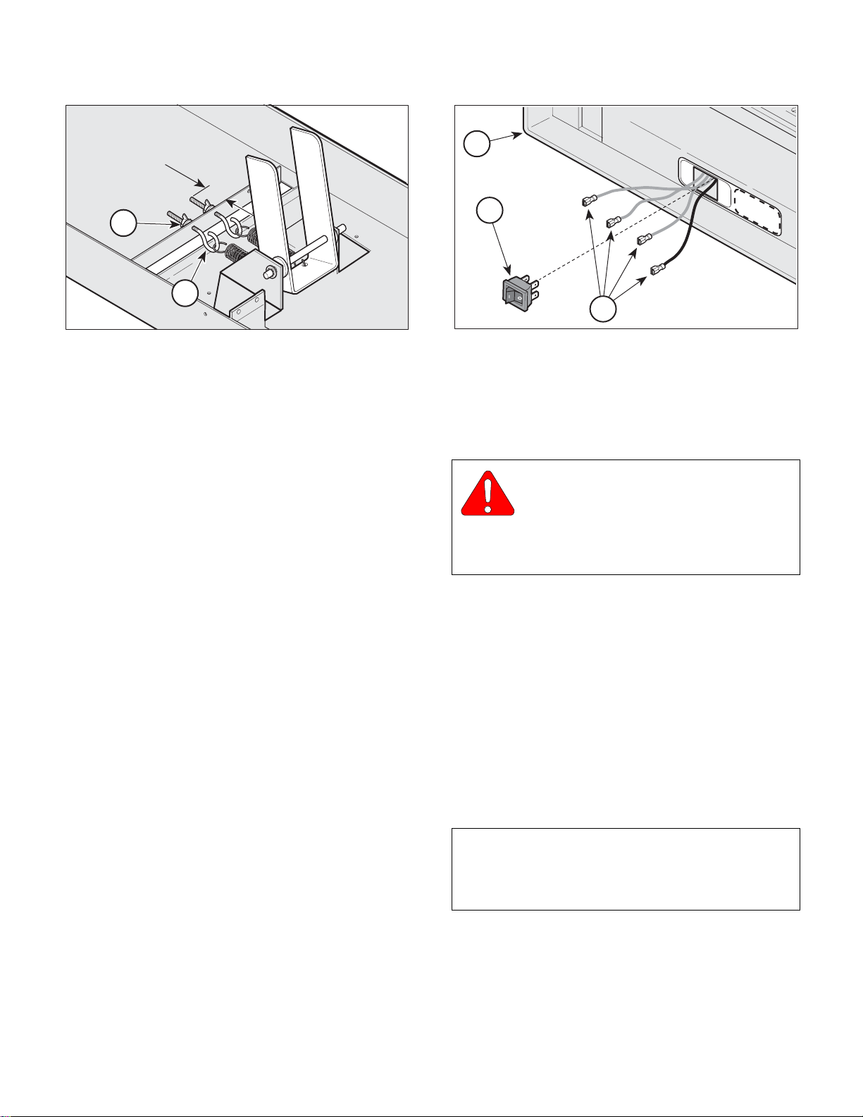
NOTE
The wing nuts (1, Figure 4-9) should be threaded
onto the eye bolts (2) approximately 1 inch (2.54 cm).
(5) Check the position of the wing nuts (1, Figure 4-
9) on the eye bolts (2) of the lift assembly.
© Midmark Corporation 1997 SF-1532 Page 4-10 Printed in U.S.A.
Rev. 7/04
MA364500
Figure 4-8. Lift Lever
(6) Rotate the back lock handles (5, Figure 4-8) to
align with the hole in the back lock assembly (3)
and insert the back support rod (1).
NOTE
With the head board in the chair position and no
weight on the table, the head board should descend
1/2 to 3/4 of the way to the horizontal position when
the back lock handles are released.
Page 29
1"
Return To Table Of Contents
1"
(2.5 cm)
(2.5 cm)
1
1
2
2
MA357000
Figure 4-9. Lift Lever
(7) Check to insure the head board (6) raises and
lowers smoothly. If necessary, adjust the wing
nuts (1, Figure 4-9) to adjust the tension on the
eye bolts (2).
MAINTENANCE / SERVICE
2
1
3
Figure 4-10. Heater ON / OFF Switch
4.8 Heater ON / OFF Switch
(Not Applicable on 304-017)
SECTION IV
ON
OFF
CAUTION
HOT
MA357100
(8) Raise the head board (6, Figure 4-8) until the
back support rod (1) is free from the back lock
assembly (3).
(9) Supporting the head board (6), install the cover
assembly (7) and secure with four screws (9).
(10) Rotate the back lock handles (5) to align with
the hole in the back lock assembly (3) and
insert the back support rod (1).
(11) Insert the cotter pin (2) in the end of the back
support rod (1) and bend over the ends of the
cotter pins.
(12) Lightly lubricate the back support rod (1), check
operation and install the drawers.
(13) Plug table power cord into wall outlet.
WARNING
Always disconnect electrical power to
the unit before removing any of the
unit's covers/shrouds or making any repairs to
prevent the possibility of electrical shock. Failure
to comply could result in personal injury.
(14) Unplug table power cord from wall outlet.
(15) Using a standard screwdriver, carefully pry
heater switch (1, Figure 4-10) out of upper wrap
weldment (2), making sure not to scratch table.
(16) Tag and disconnect the four wires (3) from
heater switch (1).
A. Installation
(1) Connect four wires (3, Figure 4-10) to heater
switch (1) (Refer to para 5.1).
NOTE
Insure that the switch ON (I) and OFF (O) symbols
are matched with proper ON or OFF designation on
the decal when installing the switch.
© Midmark Corporation 1997 SF-1532 Page 4-11 Printed in U.S.A.
Rev. 7/04
(2) Push heater switch (1) into upper wrap weld-
ment (2) until heater switch snaps into place.
(3) Plug table power cord into wall outlet.
Page 30
SECTION IV
9
11
10
6
8
7
B
Return To Table Of Contents
MAINTENANCE / SERVICE
4
3
5
1
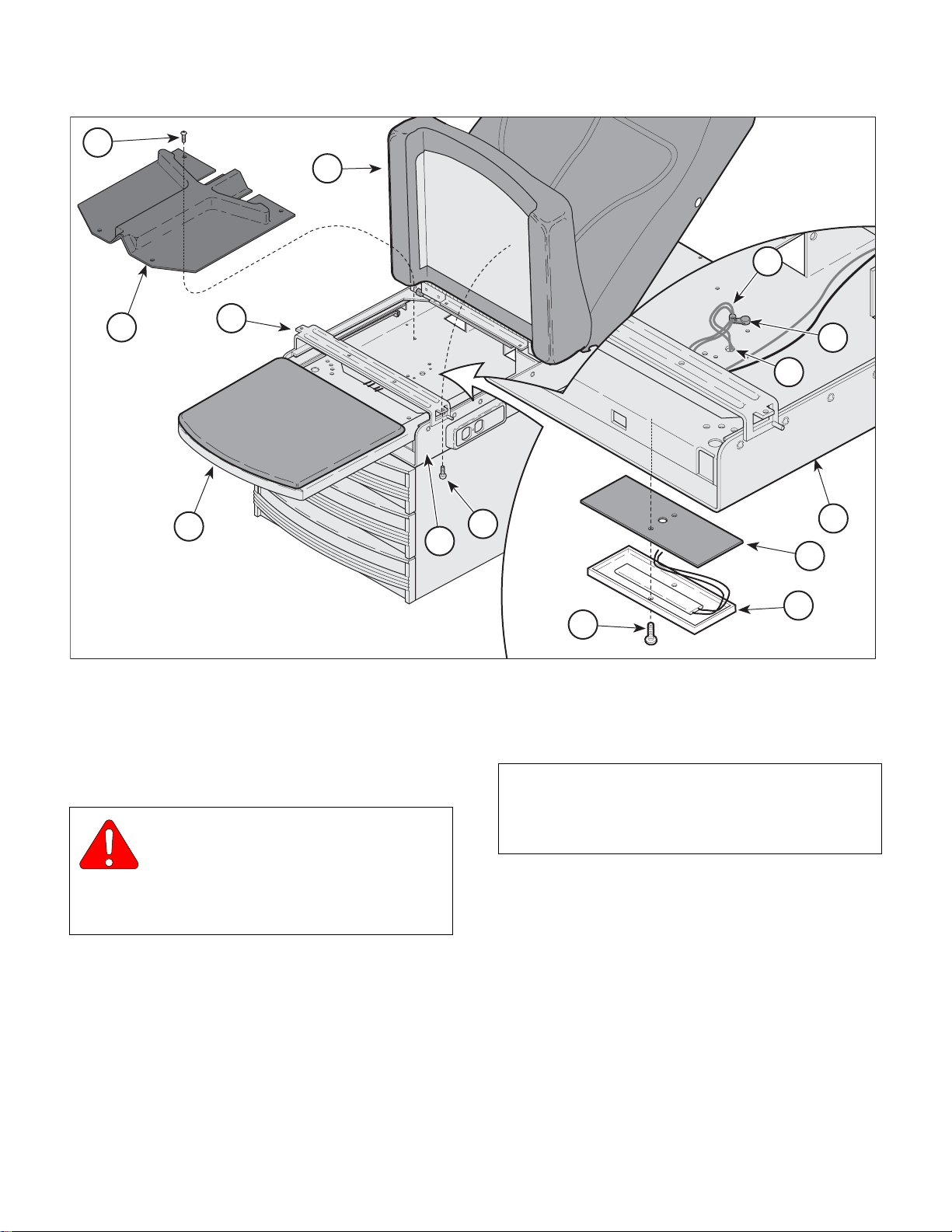
4.9 Heater Plate
(Not Applicable on 304-017)
A
2
6
Figure 4-11. Heater Plate
(4) Pull footrest section (1, Figure 4-11) out as far
as it will go.
MA363900
MA358000
A. Removal
WARNING
Always disconnect electrical power to
the unit before removing any of the
unit's covers/shrouds or making any repairs to
prevent the possibility of electrical shock. Failure
to comply could result in personal injury.
(1) Unplug table power cord from wall outlet.
(2) Remove the two drawers from foot end of table.
(3) Remove the heater ON / OFF switch (Refer to
para 4.8).
© Midmark Corporation 1997 SF-1532 Page 4-12 Printed in U.S.A.
Rev. 7/04
NOTE
For tables without Pelvic Tilt, remove two screws (2)
that secure the seat section (3) to the upper wrap
cross member (A).
(5) Raise up the seat section (3).
(6) Remove the four screws (4) and stirrup
guide (5) from the upper wrap weldment (6).
(7) Remove any wrap-n-tap wire clamps (7) secur-
ing the heater plate wiring (8) to the upper wrap
weldment (6).
(8) Remove the two screws (9), heater plate (10),
and heat shield (11) from bottom side of the
upper wrap weldment (6).
Page 31
SECTION IV
Return To Table Of Contents
MAINTENANCE / SERVICE
B. Installation
(1) Route the heater plate wires (8, Figure 4-11)
thru the heat shield (11) then thru the wire hole
(B) in the upper wrap weldment (6).
CAUTION
Be sure the heater plate wires are not
pinched by the heater plate during installation. Failure to do so could cause personal injury.
(2) Install the heat shield (11), and the heater plate
(10) on the bottom side of the upper wrap weldment (6) and secure with two screws (9).
(3) Install the heater ON / OFF switch (Refer to
para 4.8).
(4) Secure the heater plate wires (8) to the upper
wrap weldment (6) with wrap-n-tap clamps (7).
NOTE
Plug table in temporarily, turn ON the heater switch
and check to insure the heater plate begins to warm.
Unplug the table and continue with installation procedures.
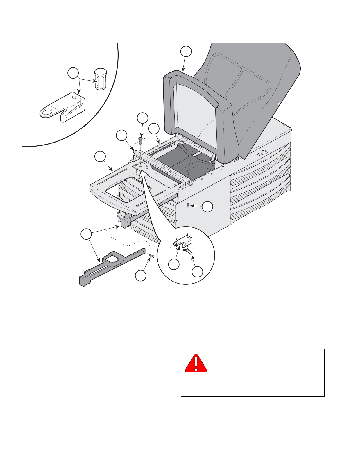
4.10 Stirrup Components
A. Removal
WARNING
Always disconnect electrical power to
the unit before removing any of the
unit's covers/shrouds or making any repairs to
prevent the possibility of electrical shock. Failure
to comply could result in personal injury.
(1) Unplug table power cord from wall outlet.
NOTE
For tables without Pelvic Tilt, remove the two screws
(1, Figure 4-12) that secure the seat section (2) to the
upper wrap cross member (A).
(2) Raise the seat section (2, Figure 4-12) up and
support it.
(3) Pull the stirrup (4) out far enough to access the
stop screw (5) and remove the stop screw (5)
from the stirrup (4).
(4) Pull the stirrup (4) out of the pivot boss (6).
(5) Install the stirrup guide (5) on the upper wrap
weldment (6) and secure with four screws (4).
(6) Lower the seat section (3). If necessary, for
tables without Pelvic Tilt, install the two screws
(2) to secure the seat section (3) to the upper
cross member (A).
(7) Push the foot rest (1) into its stowed position.
(8) Install the two drawers in the table.
(9) Plug table power cord into wall outlet.
(5) Remove the pivot boss (6) and stirrup guide
bracket (7) from the upper wrap weldment (8).
(6) If worn, remove the stirrup index spring (9) from
the stirrup guide bracket (7).
B. Installation
(1) If removed, install the stirrup index spring (9,
Figure 4-12) on the guide bracket (7).
(2) Install the guide bracket (7) in the upper wrap
weldment (8) and secure with the pivot
boss (6).
(3) Slide the stirrup (4) thru the slots (B) in the pivot
boss (6) and the guide bracket (7).
(4) Install the stop screw (5) on the stirrup (4).
(5) Push the footrest section (3) all the way into its
stowed position.
© Midmark Corporation 1997 SF-1532 Page 4-13 Printed in U.S.A.
Rev. 7/04
Page 32
SECTION IV
Return To Table Of Contents
MAINTENANCE / SERVICE
B
B
A
A
3
3
2
2
6
6
8
8
4
4
5
5
Figure 4-12. Stirrup Components
(6) Lower the seat section (2). If necessary, for
tables without Pelvic Tilt, install two screws to
secure the seat section (2) to the upper wrap
assembly (8).
(7) Plug the table power cord into wall outlet.
(8) Check the stirrups to insure they work smoothly
and lock into the various positions.
1
1
7
7
9
9
4.11 Electrical Receptacle
(120 VAC Units)
(Not Applicable on 304-017)
A. Removal
WARNING
Always disconnect electrical power to
the unit before removing any of the
unit's covers/shrouds or making any repairs to
prevent the possibility of electrical shock. Failure
to comply could result in personal injury.
MA371100
© Midmark Corporation 1997 SF-1532 Page 4-14 Printed in U.S.A.
Rev. 7/04
(1) Unplug table power cord from wall outlet.
Page 33
SECTION IV
Return To Table Of Contents
MAINTENANCE / SERVICE
6
A
2
1
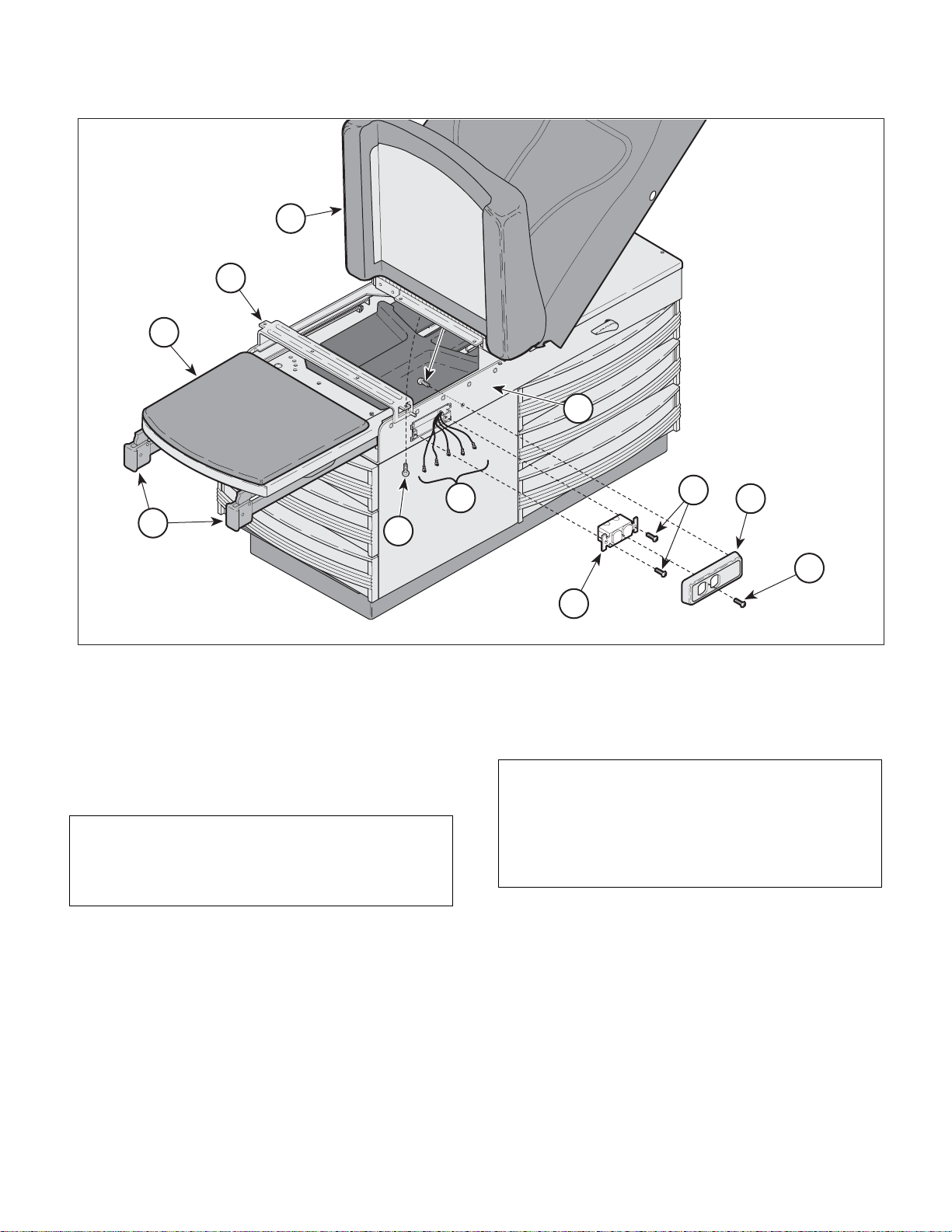
Figure 4-13. Electrical Receptacle Removal / Installation
(2) Extend the stirrups (1, Figure 4-13) and foot-
rest (2) out to full extension.
5
7
11
120 VAC Units
(7) Pull the receptacle (10) out of the upper wrap
8
10
assembly (8).
9
4
3
MA364700
(3) Remove the screw (3) from the front of the
receptacle cover (4).
NOTE
For tables without Pelvic Tilt, remove the two
screws (5) that secure the seat section (6) to the
upper wrap cross member (A).
(4) Raise up the seat section (6).
(5) Remove the screw (7) from inside the upper
wrap assembly (8) and remove the receptacle
cover (4) from the upper wrap assembly.
(6) Remove the two screws (9) that secure the
receptacle (10) to the upper wrap assembly (8).
© Midmark Corporation 1997 SF-1532 Page 4-15 Printed in U.S.A.
Rev. 7/04
NOTE
Before removing the electrical leads and ground wire
from the receptacle, tag each wire for installation onto
the replacement receptacle. If the table has a drawer
heater there will be five leads and without the drawer
heater there are three.
(8) Tag and disconnect the electrical leads and
ground wire (11) from the receptacle (10) and
remove the receptacle.
Page 34
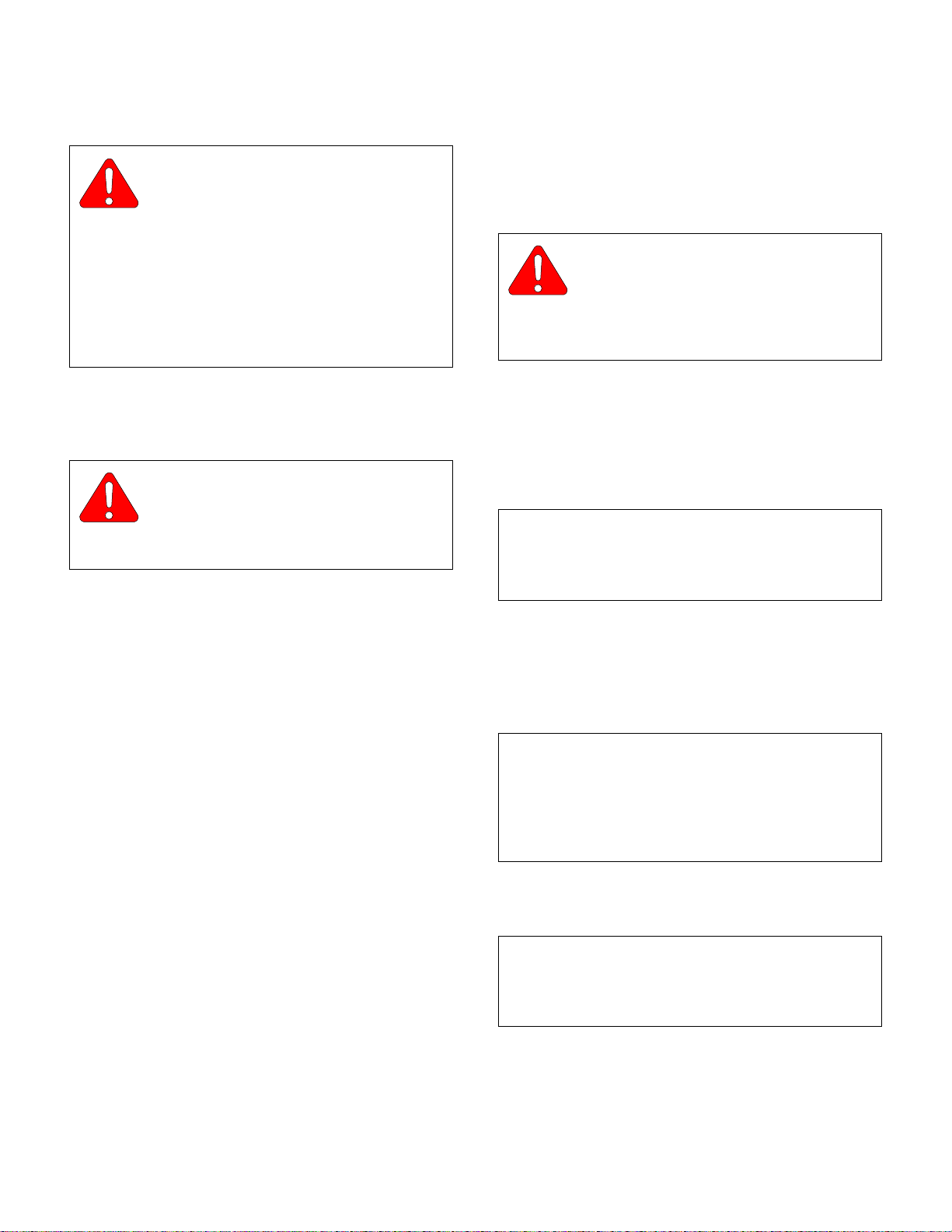
SECTION IV
Return To Table Of Contents
MAINTENANCE / SERVICE
B. Installation
CAUTION
When connecting the electrical leads and
ground wire (11, Figure 4-13) to the receptacle (10) be sure the insulation on the leads covers
sufficiently to prevent electrical shorts to the cabinet.
The black leads connect to the side of the receptacle
with the black screws and the white leads connect to
the side with the silver screws. Insure the ground
(green) lead is connected to the ground terminal on
the receptacle and to the table. Failure to do so could
result in personal injury.
(1) Connect electrical leads and ground wire (11)
to the appropriate terminals on the receptacle
(10) (Refer to para 5.1).
CAUTION
Be sure the receptacle is positioned in the
cavity of the upper wrap assembly so that
none of the electrical terminals or exposed wires are
contacting the upper wrap assembly.
(2) Insert the receptacle (10) into its cavity in the
upper wrap assembly (8) and secure with two
screws (9).
4.12 Typical Electrical Receptacle
(220 VAC Units)
(Not Applicable on 304-017)
A. Removal
WARNING
Always disconnect electrical power to
the unit before removing any of the
unit's covers/shrouds or making any repairs to
prevent the possibility of electrical shock. Failure
to comply could result in personal injury.
(1) Unplug table power cord from wall outlet.
(2) Extend the stirrups (1, Figure 4-14) out to full
extension.
(3) Extend the foot rest (2) out to full extension.
NOTE
For tables without Pelvic Tilt, remove the two
screws (3) that secure the seat section (4) to the
upper wrap cross member (A).
(4) Raise the seat section (4) up.
(3) Place the receptacle cover (4) on the receptacle
(10) and secure to upper wrap (8) with screw
(3) and screw (7).
(4) Push the footrest (2) and stirrups (1) into their
stowed positions.
(5) Lower the seat section (6). If necessary, for
tables without Pelvic Tilt, install two screws (5)
to secure the seat section (6) to the upper wrap
cross member (A).
(6) Plug the table power cord into wall outlet and
check that there is power to the receptacle.
(5) Remove two screws (5) from inside the upper
wrap (6) and partially separate the receptacle
cover (7) from the upper wrap (6).
NOTE
Before removing the electrical leads and ground wire
from the receptacle, tag each wire for installation onto
the replacement receptacle. If the table has a drawer
heater there will be five leads and without the drawer
heater there will be three.
(6) Tag and disconnect electrical leads and ground
wire (8) from receptacle (9).
NOTE
The position, as well as the number of tabs (A, Figure
4-15) on the receptacle will vary depending upon the
country the receptacle was designed for (UK shown).
© Midmark Corporation 1997 SF-1532 Page 4-16 Printed in U.S.A.
Rev. 7/04
Page 35
SECTION IV
Return To Table Of Contents
MAINTENANCE / SERVICE
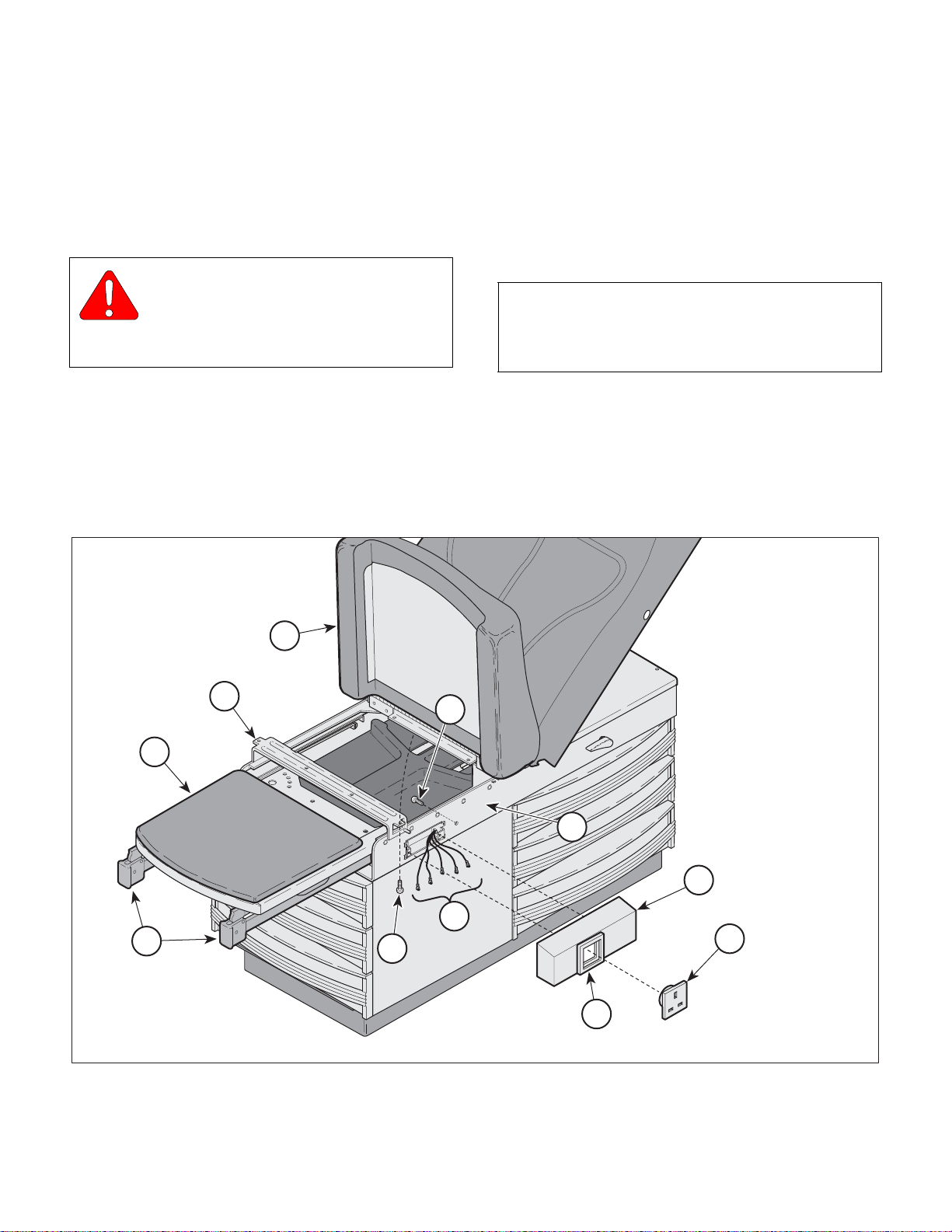
(7) Remove receptacle (1, Figure 4-15) by using a
small flat-bladed screwdriver to pry the switch
bezel (2) upward while pressing gently on the
back of the receptacle to allow the tabs (A) to
“pop” out of the switch bezel.
B. Installation
CAUTION
When connecting electrical leads and
ground wire (8, Figure 4-14) to the receptacle (9) be sure the insulation on the leads covers
sufficiently to prevent electrical shorts to the cabinet.
(1) Pull electrical leads and ground wire (8) thru
receptacle cover (7) and switch bezel (10) and
connect to proper terminals of receptacle (9)
(Refer to para 5.1).
(2) Insert receptacle (9) thru switch bezel (10) and
receptacle cover (7), pushing gently until receptacle locks into place.
(3) Align receptacle cover (7) with holes in upper
wrap (6) and secure with two screws (5).
(4) Lower the seat section (4).
NOTE
For tables without Pelvic Tilt, install the two
screws (3) that secure the seat section (4) to the
upper wrap cross member (A).
(5) Push the footrest (2) and stirrups (1) into their
stowed positions.
(6) Plug the table power cord into wall outlet and
check that there is power to the receptacle.
4
A
5
2
6
7
8
1
3
10
Figure 4-14. Typical Electrical Receptacle
220 VAC Units (UK shown)
9
MA485800
© Midmark Corporation 1997 SF-1532 Page 4-17 Printed in U.S.A.
Rev. 7/04
Page 36
SECTION IV
Return To Table Of Contents
MAINTENANCE / SERVICE
A
2
CRAFTSMAN
1
Figure 4-15. 220 VAC Electrical Receptacle
(UK shown)
MA486200
4.13 Fuse (220 VAC Units Only)
(Not Applicable on 304-017)
A. Removal
WARNING
Always disconnect electrical power to
the unit before removing any of the
unit's covers/shrouds or making any repairs to
prevent the possibility of electrical shock. Failure
to comply could result in personal injury.
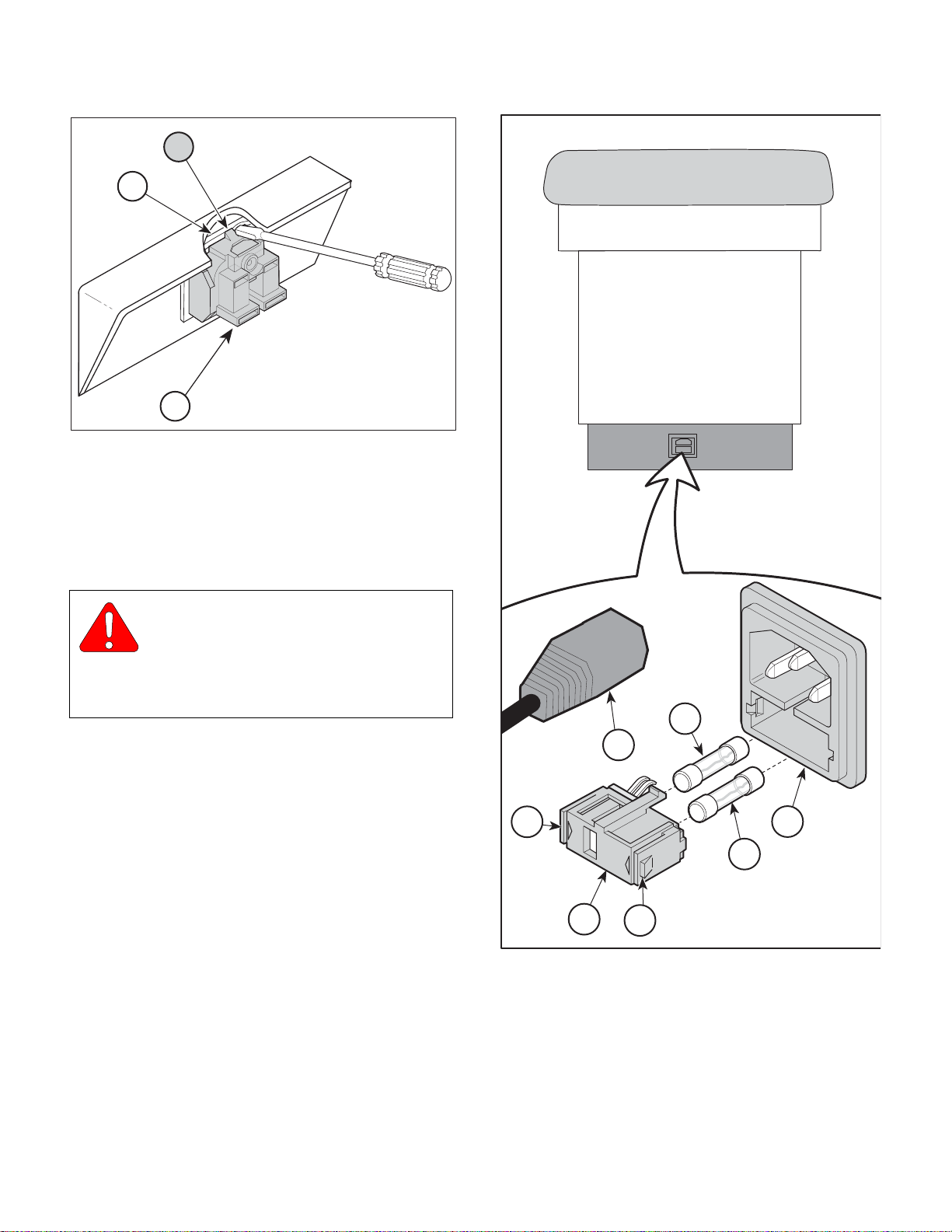
(1) Unplug table power cord (1, Figure 4-16) from
AC inlet (2).
(2) Using a small flat-bladed screwdriver, press
inward on two locking tabs (A) and pull fuse
drawer (3) from AC inlet (2).
(3) Pull two fuses (4) out of fuse drawer (3).
A
4
1
240
230
230
220
2
4
B. Installation
(1) Insert two fuses (4) into fuse drawer (3).
(2) Insert fuse drawer (3) into AC inlet (2) and push
until fuse drawer locks into place.
(3) Plug table power cord (1) into AC inlet (2).
© Midmark Corporation 1997 SF-1532 Page 4-18 Printed in U.S.A.
Rev. 7/04
3
A
Figure 4-16. Fuse
MA486000
Page 37
SECTION IV
A
2
5
6
1
4
3
Return To Table Of Contents
MAINTENANCE / SERVICE
4.14 AC Inlet (220 VAC Units)
(Not Applicable on 304-017)
A. Removal
WARNING
Always disconnect electrical power to
the unit before removing any of the
unit's covers/shrouds or making any repairs to
prevent the possibility of electrical shock. Failure
to comply could result in personal injury.
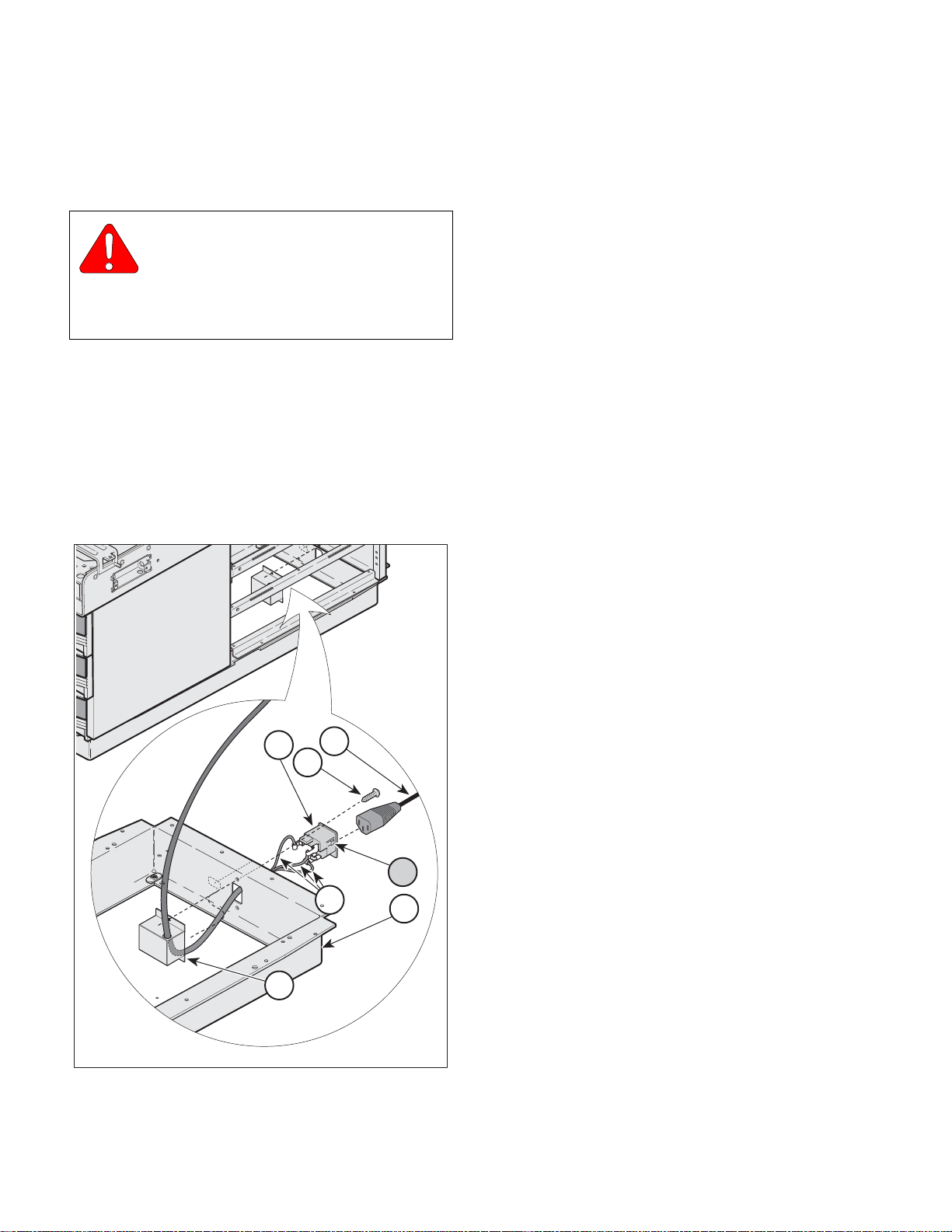
(1) Unplug table power cord (1, Figure 4-17) from
AC inlet (2).
(2) Remove three side drawers to gain access to
AC inlet cover (3).
(3) Remove two screws (4) and partially separate
AC inlet cover (3) from base assembly (5).
(4) Tag and disconnect electrical leads (6) from ter-
minals of AC inlet (2).
(5) Remove AC inlet (2) from base assembly (5) by
simultaneously depressing two tabs (A) (one
tab on each side of AC inlet) and pushing outward.
B. Installation
(1) Insert AC inlet (2) thru hole in base
assembly (5) and push inward until AC inlet
locks into place.
(2) Connect electrical leads (6) to proper terminals
of AC inlet (2) (Refer to para 5.1).
(3) Align AC inlet cover (3) with holes in base
assembly (5) and secure with two screws (4).
(4) Install three side drawers.
(5) Plug table power cord (1) into AC inlet (2) and
check that there is power to the receptacle.
Figure 4-17. AC Inlet
© Midmark Corporation 1997 SF-1532 Page 4-19 Printed in U.S.A.
Rev. 7/04
MA486100
Page 38
SECTION IV
Return To Table Of Contents
MAINTENANCE / SERVICE
The following procedures are Only for the Model 304-017
(IPET) Integrated Patient Exam Tables
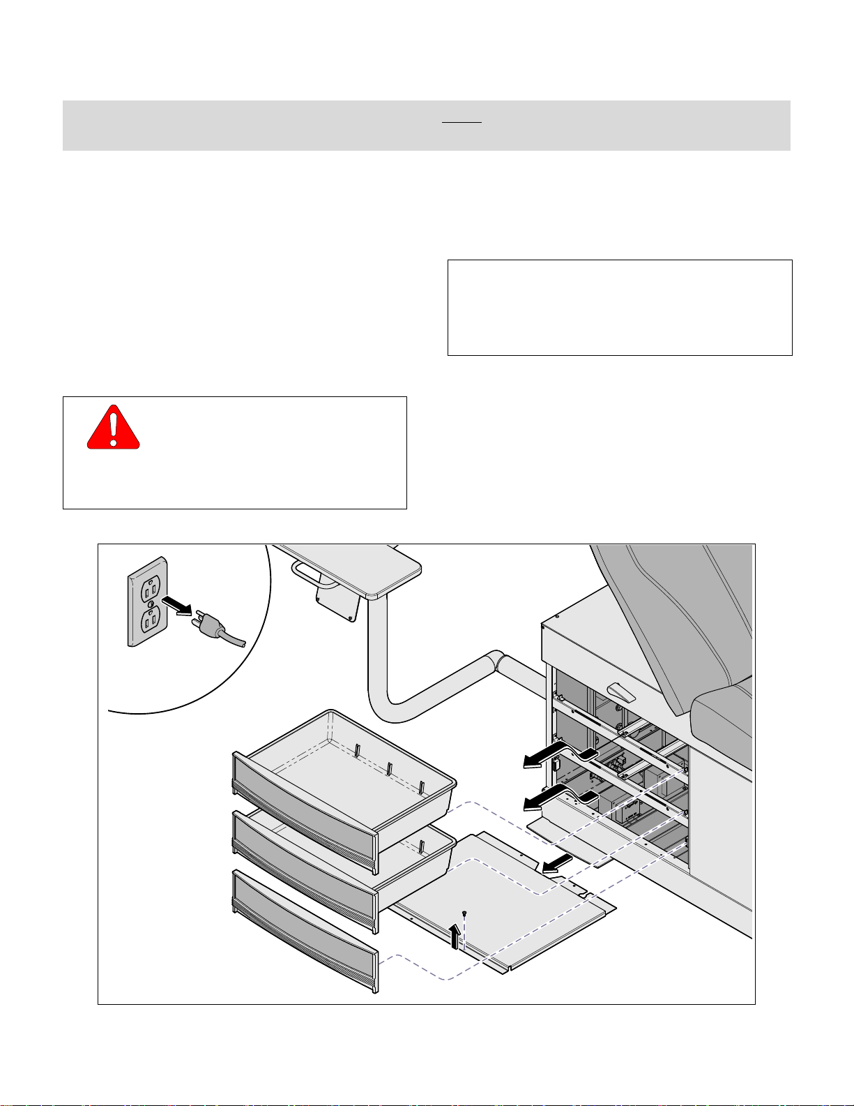
4.15 Accessing Electrical Components
The Model 304-017 Table has:
• Four Line Fuses.
• Two Isolation Transformers.
• Two Power Strips each with 6 receptacles.
• One LAN (Local Area Network) Connection.
In order to access these components refer to the following procedures:
A. Accessing Electrical Components
WARNING
Always disconnect electrical power to
the unit before removing any of the
unit's covers/shrouds or making any repairs to
prevent the possibility of electrical shock.
Failure to comply could result in personal injury.
(1) Unplug table power cord.
(2) Remove the two head-end, side drawers and
magnetic drawer front.
NOTE
If a computer or other electronic monitoring
device(s) are located in the area behind the magnetic drawer front, they must be removed in order to
access the components.
(3) Tag all cables or leads for later reinstallation,
disconnect them, and remove the computer or
monitoring device.
(4) Remove the bottom access panel (4 screws).
© Midmark Corporation 1997 SF-1532 Page 4-20 Printed in U.S.A.
Rev. 7/04
MA678100i
Page 39
SECTION IV
Return To Table Of Contents
MAINTENANCE / SERVICE
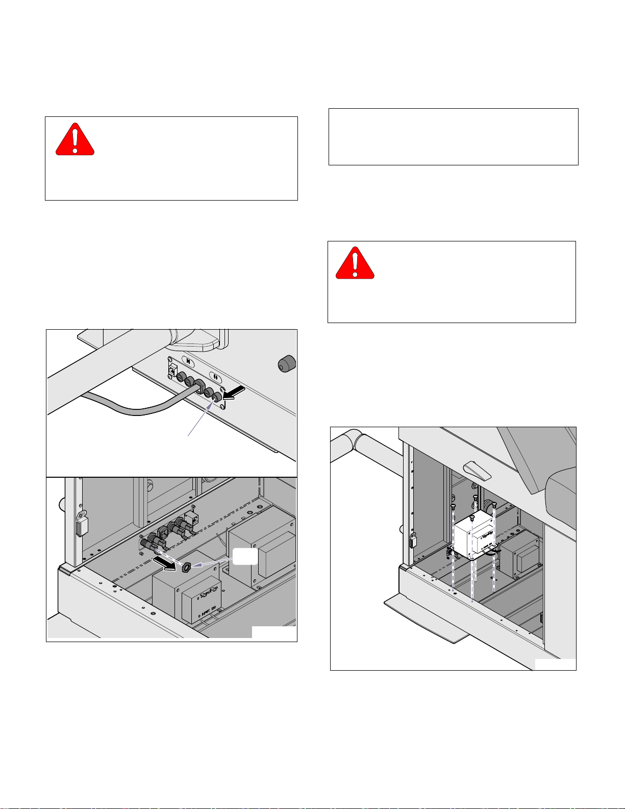
4.16 Fuse Holders
A. Removal
WARNING
Always disconnect electrical power to
the unit before removing any of the
unit's covers/shrouds or making any repairs to
prevent the possibility of electrical shock.
Failure to comply could result in personal injury.
(1) Access the fuse holders (Refer to para 4.15,
Accessing Electrical Components).
(2) Tag and disconnect the electrical leads to the
fuse holder.
(3) Remove the fuse holder cap.
(4) Remove the nut.
(5) Remove the fuse holder assembly from the
outside of the lower panel.
(2) Connect the electrical leads (Refer to 304-017
wiring / schematic in Section 5).
NOTE
Assure the correct fuse(s) is/are in place before
plugging unit into outlet (Refer to User’s Guide or
Wiring Diagram in Section 5).
(3) Install the bottom access panel and drawers.
4.17 Transformer(s)
A. Removal
WARNING
Always disconnect electrical power to
the unit before removing any of the
unit's covers/shrouds or making any repairs to
prevent the possibility of electrical shock.
Failure to comply could result in personal injury.
(1) Access the transformers (Refer to para 4.15,
Accessing Electrical Components).
(2) Tag and disconnect the electrical leads to the
transformer(s).
(3) Remove the screws holding the transformer in
position and remove the transformer.
Cap
Nut
B. Installation
(1) Insert the fuse holder through the hole in the
lower base wrap and install the nut.
MA678200i
MA678300i
B. Installation
(1) Place the new transformer in position and
secure with screws.
© Midmark Corporation 1997 SF-1532 Page 4-21 Printed in U.S.A.
Rev. 7/04
Page 40
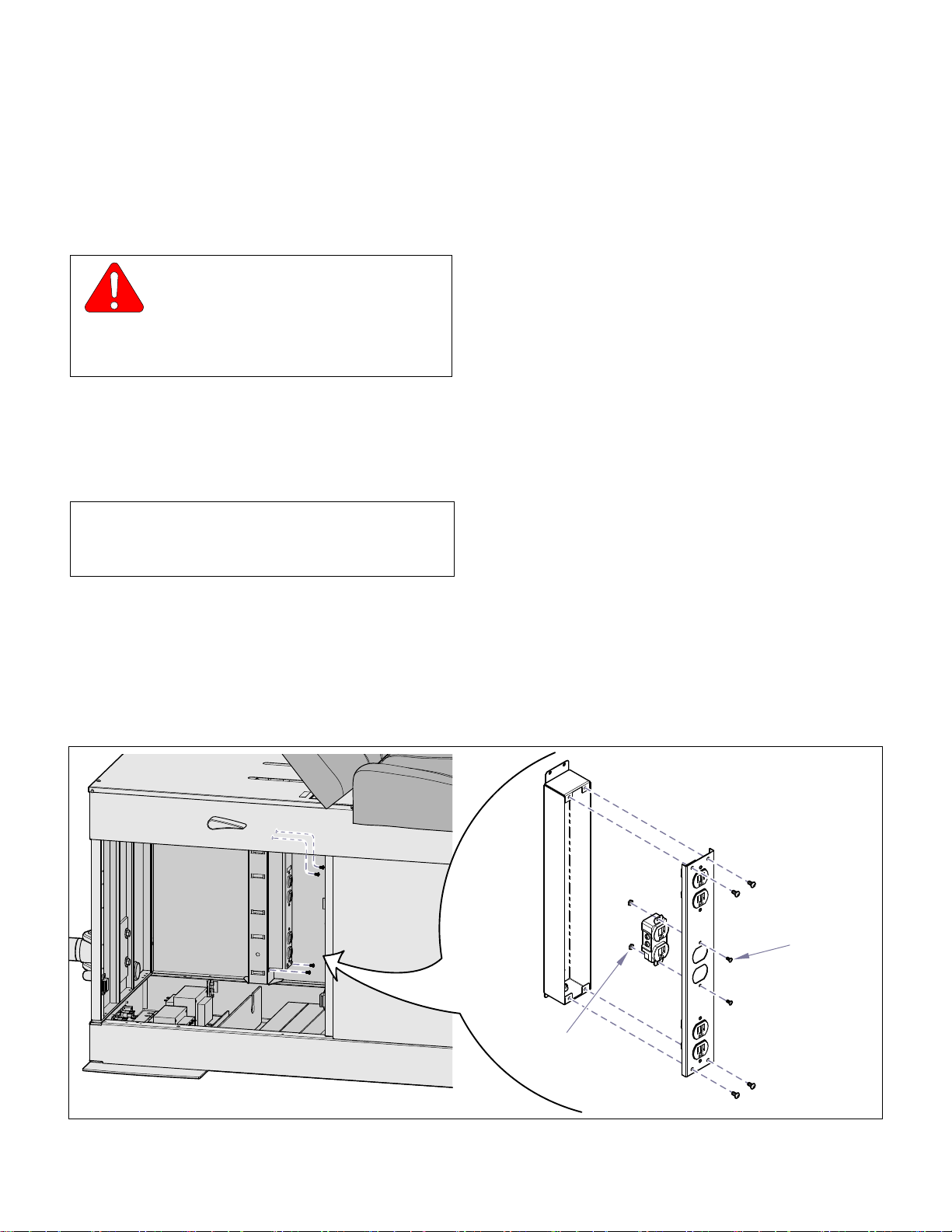
SECTION IV
Return To Table Of Contents
MAINTENANCE / SERVICE
(2) Connect the input leads to the correct fuses (F1
& F2) or (F3 & F4) depending upon which transformer is being replaced.
(3) Install the bottom access panel and drawers
4.18 Power Strips
A. Removal
WARNING
Always disconnect electrical power to
the unit before removing any of the
unit's covers/shrouds or making any repairs to
prevent the possibility of electrical shock.
Failure to comply could result in personal injury.
(1) Access the Power Strips (Refer to para 4.15,
Accessing Electrical Components).
(2) Tag and disconnect the electrical leads from the
power strip(s) to the transformer(s).
(3) Remove the power strip(s) (four screws).
NOTE
If necessary, the Power Strip contains 3 individual,
duplex receptacles that can be replaced separately.
B. Installation
(1) Place the new duplex receptacle in position on
the cover and secure with two mounting screws
and nuts.
(2) Position the cover on the power strip box and
secure with four screws.
(3) Secure the Power Strip assembly to the cabinet
with four screws.
(4) Connect the electrical leads to the transformer.
(5) Install the bottom access panel and drawers.
(4) Remove the four screws that secure the recep-
tacle cover to the box.
(5) Tag and disconnect the electrical leads to the
duplex receptacle.
(6) Remove the mounting screws and nuts and
remove the receptacle.
Receptacle
Nut
Receptacle
Mounting
Screw
© Midmark Corporation 1997 SF-1532 Page 4-22 Printed in U.S.A.
Rev. 7/04
MA678400i
Page 41
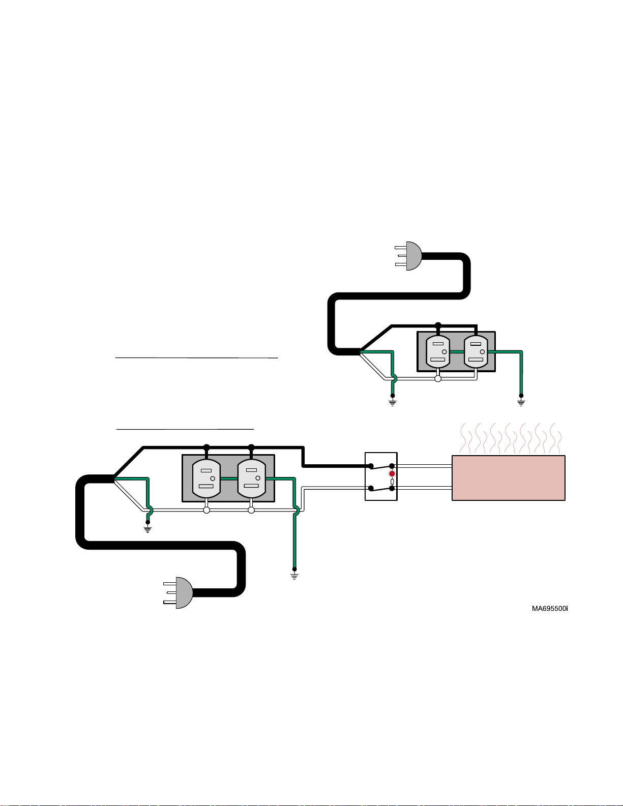
SECTION V
Return To Table Of Contents
SCHEMATICS AND DIAGRAMS
5.1 Electrical Schematics / Wiring
Diagrams
Figure 5-1 illustrates the logic / current flow and wiring
connections between the electrical components in the
120 VAC table, as Figure 5-2 does for the 220 VAC
table.
Figure 5-3 is for the Model 304-017 (120 VAC )
Intergrated Patient Exam Table.
Models 304-001 thru -004
& -007 thru -010
SECTION V
SCHEMATICS AND DIAGRAMS
115 VAC, 12 AMP
60 HZ Supply
(MUST BE GROUNDED)
015-0066-03
UNIT WITHOUT HEATER
UNIT WITH HEATER
GREEN
115 VAC, 12 AMP
60 HZ Supply
(MUST BE GROUNDED)
BLACK
WHITE
DUPLEX RECEPTACLE
015-0066-03
015-0064-03
015-0064-02
GREEN
015-0141-00
BLACK
GREEN
WHITE
BLACK
WHITE
4
1
ILLUMINATED
HEATER SWITCH
(IN "ON" POSITION)
BLACK
Duplex
Receptacle
GREEN
WHITE
5
WHITE
WHITE
2
60 WATT
015-0141-00
Heater is ON
© Midmark Corporation 1997 SF-1532 Page 5-1 Printed in U.S.A.
Rev. 1/05
Figure 5-1. Electrical Schematic / Wiring Diagram
304 (-001 thru -004, -007 thru -014 120 VAC Units
Page 42
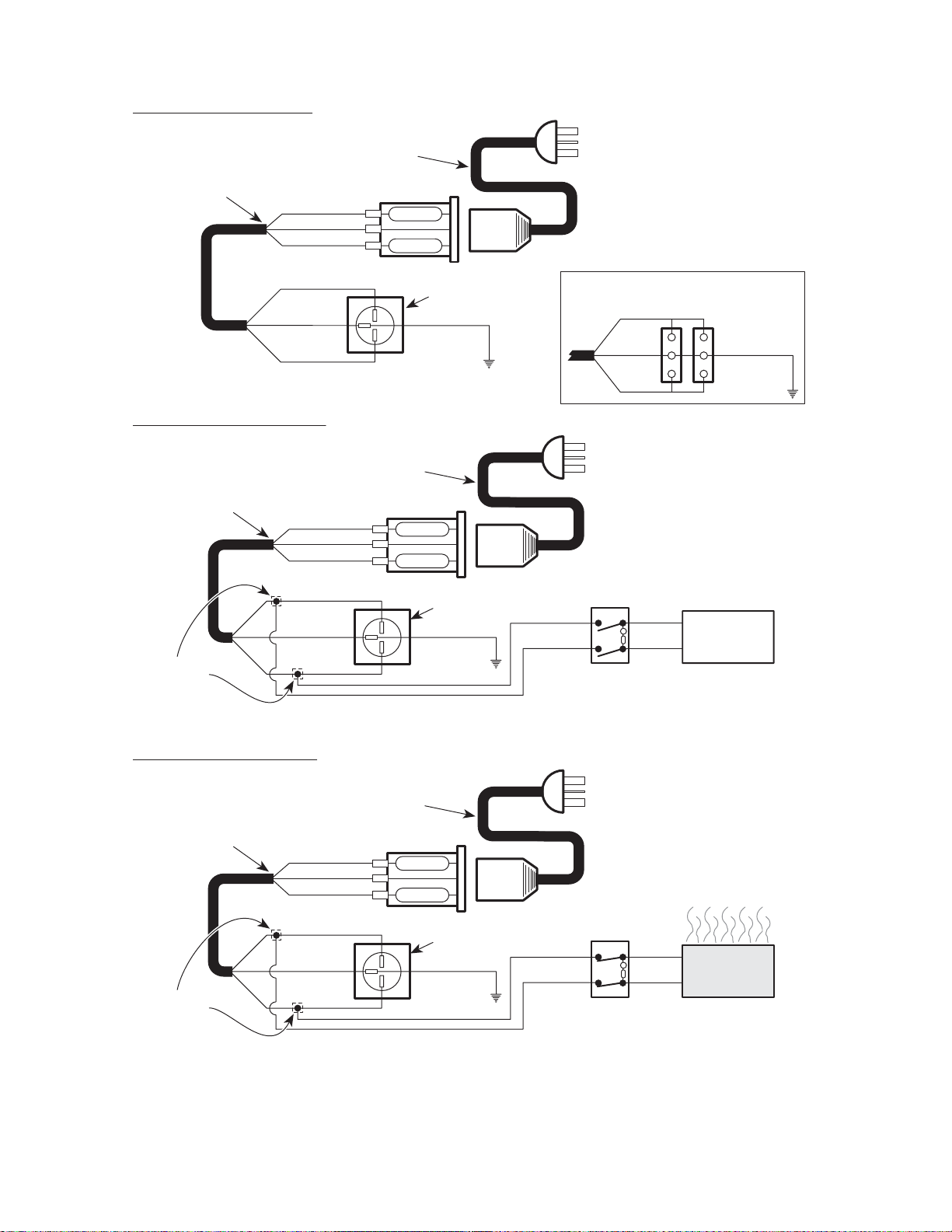
SECTION V
Return To Table Of Contents
SCHEMATICS AND DIAGRAMS
UNIT WITHOUT HEATER
(Refer to "Receptacle Assembly
APPLIANCE INLET
WIRING HARNESS
015-1250-00
[Export]" in Section VI)
GREEN / YELLOW
BROWN
GREEN / YELLOW
UNIT WITH HEATER (OFF)
(Refer to "Receptacle Assembly
APPLIANCE INLET
WIRING HARNESS
015-1250-00
GREEN / YELLOW
CORDSET
Fuses (2): 015-0346-20
BROWN
BLUE
BLUE
CORDSET
[Export]" in Section VI)
Fuses (2): 015-0346-20
BROWN
BLUE
6.3 Amp
6.3 Amp
EXPORT RECEPTACLE
(Refer to "Receptacle Assembly
[Export]" in Section VI)
YELLOW / GREEN
015-0547-01
6.3 Amp
6.3 Amp
220/240 V.A.C. 10 AMP.
50/60 HZ. SUPPLY
(MUST BE GROUNDED)
(Refer to "Receptacle Assembly
BROWN
GREEN /
YELLOW
BLUE
220/240 V.A.C. 10 AMP.
50/60 HZ. SUPPLY
(MUST BE GROUNDED)
ITALIAN RECEPTACLES
[Export]" in Section VI)
YELLOW / GREEN
015-0547-01
GREEN / YELLOW
T-TAP DISCONNECT
015-0685-00
UNIT WITH HEATER (ON)
(Refer to "Receptacle Assembly
APPLIANCE INLET
WIRING HARNESS
015-1250-00
GREEN / YELLOW
GREEN / YELLOW
T-TAP DISCONNECT
015-0685-00
BROWN
BLUE
CORDSET
[Export]" in Section VI)
Fuses (2): 015-0346-20
BROWN
BLUE
BROWN
BLUE
EXPORT RECEPTACLE
(Refer to "Receptacle Assembly
[Export]" in Section VI)
YELLOW / GREEN
015-0547-01
6.3 Amp
6.3 Amp
EXPORT RECEPTACLE
(Refer to "Receptacle Assembly
[Export]" in Section VI)
YELLOW / GREEN
015-0547-01
WHITE
015-0064-10
BLACK
015-0064-11
HEATER SWITCH
(IN "OFF" POSITION)
220/240 V.A.C. 10 AMP.
(MUST BE GROUNDED)
WHITE
015-0064-10
BLACK
015-0064-11
ILLUMINATED
HEATER SWITCH
(IN "ON" POSITION)
4
5
WHITE
1
WHITE
2
50/60 HZ. SUPPLY
4
5
WHITE
1
WHITE
2
50 WATT
HEATER
50 WATT
HEATER
MA
5860
00
Figure 5-2. Electrical Schematic / Wiring Diagram 304(-005, -006, -015, -016) 220 VAC Units
Used on Units with Serial Numbers GL1000 thru GL1154 & LC1000 thru LC2092
© Midmark Corporation 1997 SF-1532 Page 5-2 Printed in U.S.A.
Rev. 7/05
Page 43
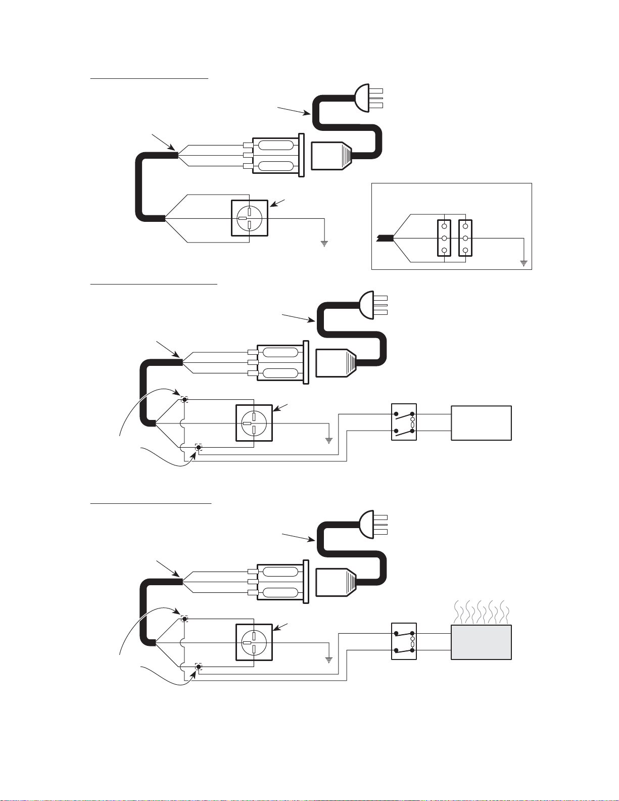
UNIT WITHOUT HEATER
Return To Table Of Contents
SECTION V
SCHEMATICS AND DIAGRAMS
(Refer to "Receptacle Assembly
APPLIANCE INLET
WIRING HARNESS
015-1535-00
[Export]" in Section VI)
GREEN / YELLOW
BROWN
GREEN / YELLOW
UNIT WITH HEATER (OFF)
(Refer to "Receptacle Assembly
APPLIANCE INLET
WIRING HARNESS
015-1535-00
GREEN / YELLOW
CORDSET
Fuses (2): 015-0346-20
BROWN
BLUE
BLUE
CORDSET
[Export]" in Section VI)
Fuses (2): 015-0346-20
BROWN
BLUE
6.3 Amp
6.3 Amp
EXPORT RECEPTACLE
(Refer to "Receptacle Assembly
[Export]" in Section VI)
YELLOW / GREEN
015-0547-01
6.3 Amp
6.3 Amp
220/240 V.A.C. 10 AMP.
50/60 HZ. SUPPLY
(MUST BE GROUNDED)
(Refer to "Receptacle Assembly
BROWN
GREEN /
YELLOW
BLUE
220/240 V.A.C. 10 AMP.
50/60 HZ. SUPPLY
(MUST BE GROUNDED)
ITALIAN RECEPTACLES
[Export]" in Section VI)
YELLOW / GREEN
015-0547-01
GREEN / YELLOW
T-TAP DISCONNECT
015-0685-00
UNIT WITH HEATER (ON)
(Refer to "Receptacle Assembly
APPLIANCE INLET
WIRING HARNESS
015-1535-00
GREEN / YELLOW
GREEN / YELLOW
T-TAP DISCONNECT
015-0685-00
BROWN
BLUE
CORDSET
[Export]" in Section VI)
Fuses (2): 015-0346-20
BROWN
BLUE
BROWN
BLUE
EXPORT RECEPTACLE
(Refer to "Receptacle Assembly
[Export]" in Section VI)
YELLOW / GREEN
015-0547-01
6.3 Amp
6.3 Amp
EXPORT RECEPTACLE
(Refer to "Receptacle Assembly
[Export]" in Section VI)
YELLOW / GREEN
015-0547-01
WHITE
015-0064-10
BLACK
015-0064-11
HEATER SWITCH
(IN "OFF" POSITION)
220/240 V.A.C. 10 AMP.
(MUST BE GROUNDED)
WHITE
015-0064-10
BLACK
015-0064-11
ILLUMINATED
HEATER SWITCH
(IN "ON" POSITION)
4
5
WHITE
1
WHITE
2
50/60 HZ. SUPPLY
4
5
WHITE
1
WHITE
2
50 WATT
HEATER
50 WATT
HEATER
MA
586001
Figure 5-2. Electrical Schematic / Wiring Diagram 304(-005, -006, -015, -016) 220 VAC Units
Used on Units with Serial Numbers GL1155 & LC2093 thru Present
© Midmark Corporation 1997 SF-1532 Page 5-3 Printed in U.S.A.
Rev. 7/05
Page 44
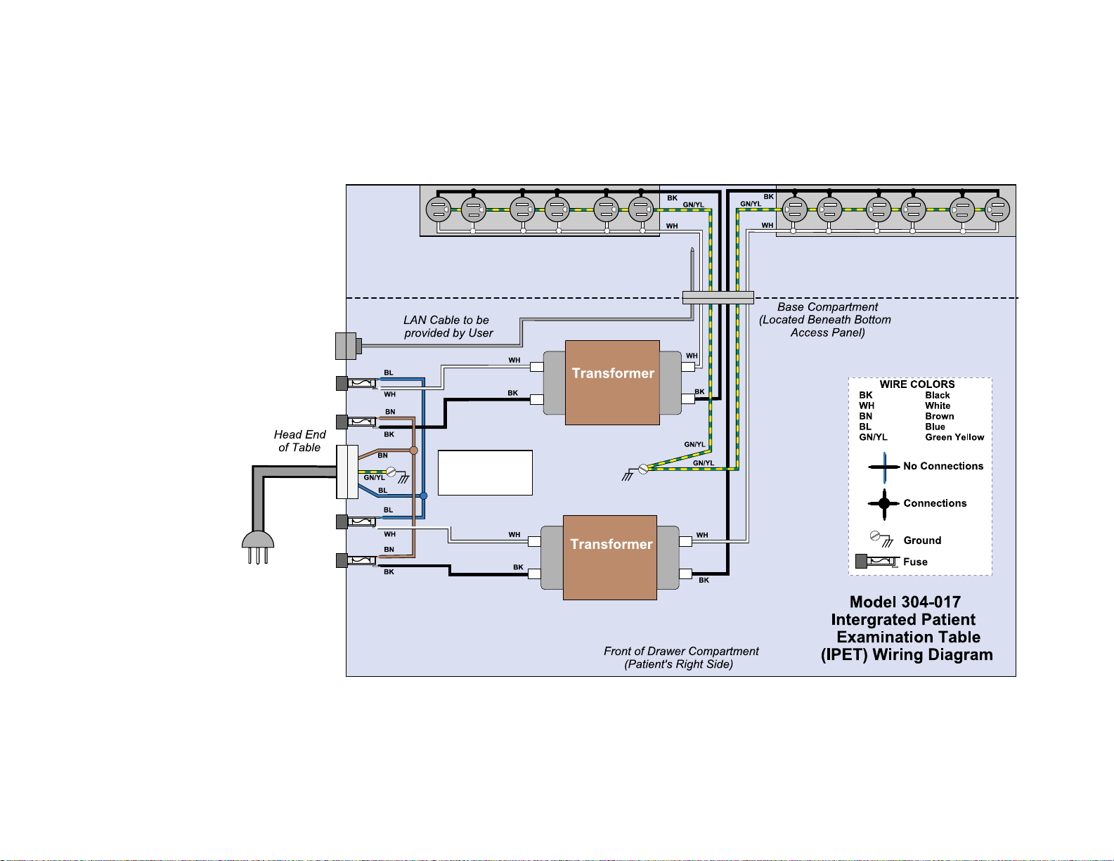
SECTION V
Return To Table Of Contents
© Midmark Corporation 1997 SF-1532 Page 5-4 Printed in U.S.A.
SCHEMATICS AND DIAGRAMS
Figure 5-3. Electrical Schematic / Wiring Diagram 304-017 (120 VAC Units)
Rev. 7/04
Used on Units with Serial Numbers VXXXXX thru Present
Power Strip (Center)
5 Amp Maximum Load
Power Strip (Corner)
5 Amp Maximum Load
LAN
Connection
F1
In
120 VAC to 120 VAC
5 Amp
Out
F2
Fuse
Pt.# 015-0346-20
250 VAC 6.3 Amp
5mm x 20mm "Slo-Blo"
F3
F4
Supply
120 VAC
15 Amp Minimum / 50-60 Hz
(Dedicated Circuit)
Input
120 VAC to 120 VAC
5 Amp
Output
MA658800i
Page 45

SECTION VI
Return To Table Of Contents
PARTS LIST
SECTION VI
PARTS LIS T
6.1 Introduction
The illustrated parts list provides information for identifying and ordering the parts necessary to maintain the
unit in peak operating condition. Refer to paragraph 1.5
for parts ordering information.
6.2 Description of Columns
The Item column of the parts list gives a component its
own unique number. The same number is given to the
component in the parts illustration. This allows a part
number of a component to be found if the technician
can visually spot the part on the illustration. The technician simply finds the component in question on the illustration and notes the item number of that component.
Then, he finds that item number in the parts list. The
row corresponding to the item number gives the technician the part number, a description of the component,
and quantity of parts per subassembly. Also, if a part
number is known, the location of that component can be
determined by looking for the item number of the component on the illustration.
The Part No. column lists the MIDMARK part number
for that component.
The Description column provides a physical description
of the component.
The Qty. column lists the number of units of a particular
component that is required for the subassembly. The
letters “AR” denote “as required” when quantities of a
particular component cannot be determined, such as:
adhesive.
Bullets { • } in the Part No. column and the Description
column show the indenture level of a component. If a
component does not have a bullet, it is a main component of that illustration. If a component has a bullet, it is
a subcomponent of the next component listed higher in
the parts list than itself that does not have a bullet. Likewise, if a component has two bullets, it is a subcomponent of the next component listed higher in the parts list
than itself that has only one bullet.
6.3 Torque Specifications and Important
Assembly Notes
When specific assembly torque specifications, measurements, or procedures have been identified, by our
engineering department, as required to assure proper
function of the unit, those torque specifications measurements, and procedures will be noted on the parts
illustrations. Adherence to these requirements is
essential.
© Midmark Corporation 1999 SF-1532 Printed in U.S.A.
Always Specify Model & Serial Number
Page 6-1
Page 46
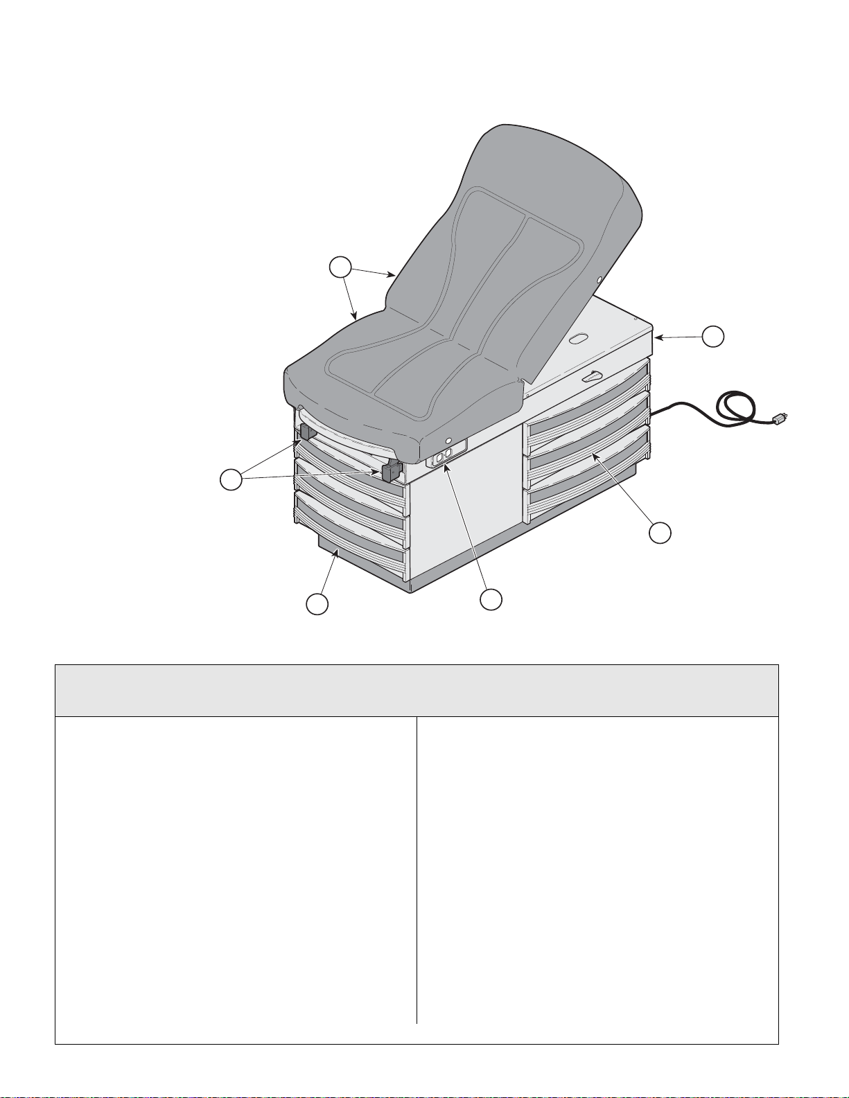
Pictorial Index
1
2
3
5
6
4
Return To Table Of Contents
SECTION VI
PARTS LIS T
MA354000
Used on units with Serial Number GJ1000 & GK1000 thru Present
Used on units with Serial Number V2200 thru Present
Item Part No. Description Page Item Part No. Description Page
304-001-xxx 304 Exam Table - R.H. (110 V.) with
304-002-xxx 304 Exam Table - L.H. (110 V.) with
304-003-xxx 304 Exam Table - R.H. (110 V.) with
304-004-xxx 304 Exam Table - L.H. (110 V.) with
Note: The -xxx in the model number
denotes upholstery color.
Refer to color code chart on this page
Vacu-Form Upholstery
{serial # prefix [GJ]}......................... 6-2
Vacu-Form Upholstery
{serial # prefix [GJ]}......................... 6-2
Vacu-Form Upholstery (w/ Heater
& Pelvic Lift) {serial # prefix [GK]}.... 6-2
Vacu-Form Upholstery (w/ Heater
& Pelvic Lift) {serial # prefix [GK]}.... 6-2
Always Specify Model & Serial Number
1 • • Table Top Components .................... 6-3
2 • • Upper Wrap Components ................ 6-5
3 • • Stirrup Components .........................6-6
4 • • Cabinet Components .......................6-7
5 • • Step Assembly ................................. 6-9
6 • • Electrical Components ...................6-10
Available Accessories
Refer to MEDICAL ACCESSORY BOOK {004-0096-00}
9A01010 Knee Crutch Set ..............................9A01
9A0200* Armboard Assembly ........................ 9A02
9A04001 Procto Rest Assembly .....................9A04
9A70000 Stainless Steel Treatment Pan............ 6-5
9A104001 Urology Drain Pan .........................9A104
9A180002 Welch Allyn Bracket .......................9A180
9A20600* Knee Crutch Set ............................ 9A206
9A21000* Sideboard Assembly......................9A210
9A28100* Welch Allyn Bracket ....................9A281
© Midmark Corporation 1999 SF-1532 Printed in U.S.A.
Rev. 3/08
6-2
Page 47
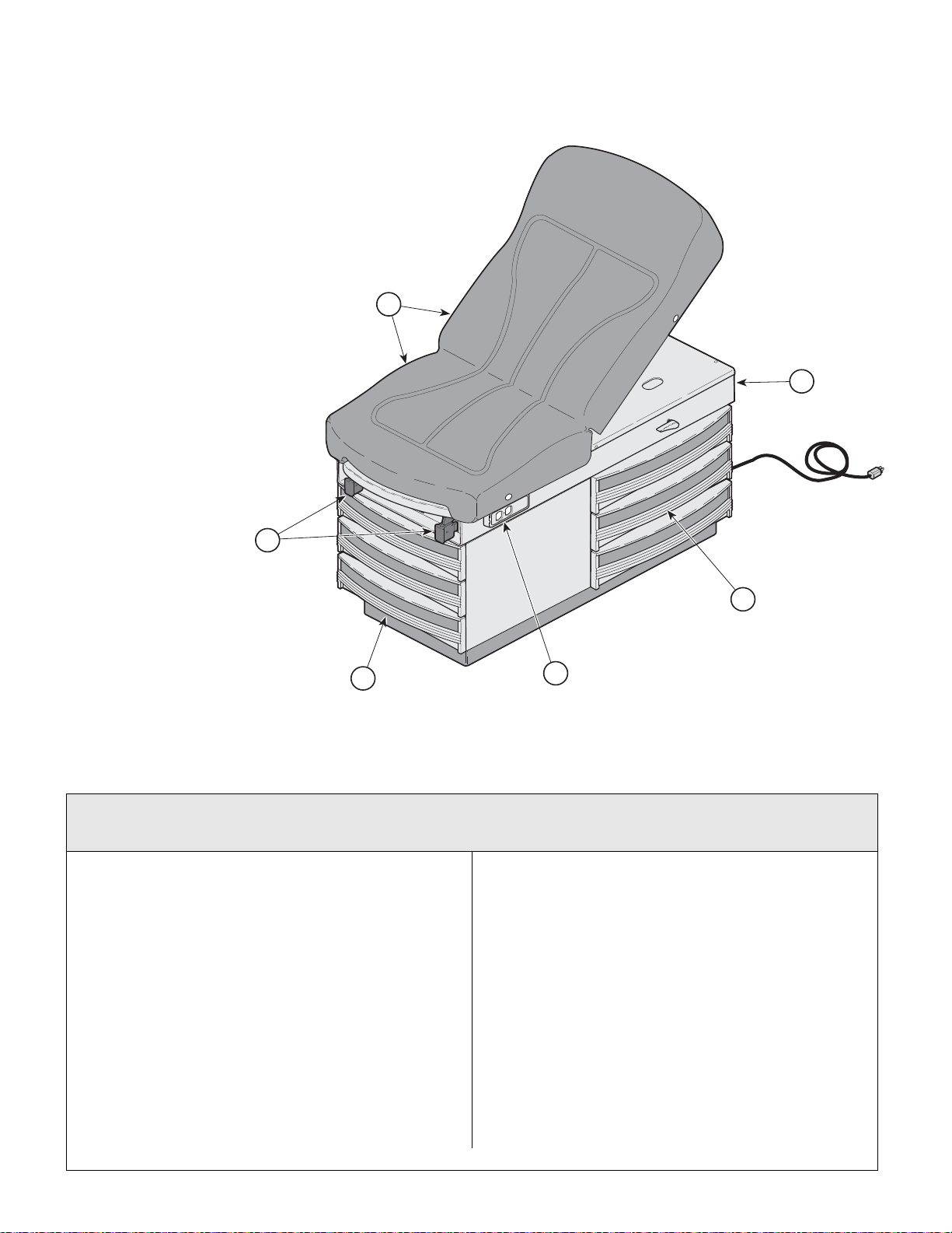
1
2
3
5
6
4
Pictorial Index
Return To Table Of Contents
SECTION VI
PARTS LIS T
Used on units with Serial Number GL1000 thru Present
Item Part No. Description Page Item Part No. Description Page
304-005-xxx 304 Exam Table - R.H. Export (220 V.)
304-006-xxx 304 Exam Table - L.H. Export (220 V.)
1 • • Table Top Components.....................6-4
2 • • Upper Wrap Components ................6-5
3 • • Stirrup Components .........................6-6
4 • • Cabinet Components .......................6-8
© Midmark Corporation 1999 SF-1532 Printed in U.S.A.
Used on units with Serial Number V2200 thru Present
Note: The -xxx in the model number
denotes upholstery color.
Refer to color code chart on this page
with SoftTouch Upholstery
{serial # prefix [GL]).......................6-2.1
with SoftTouch Upholstery
{serial # prefix [GL]).......................6-2.1
Rev. 3/08
MA354000
5 • • Step Assembly................................. 6-9
6 • • Electrical Components................... 6-11
Available Accessories
Refer to MEDICAL ACCESSORY BOOK {004-0096-00}
9A01010 Knee Crutch Set.............................. 9A01
9A0200* Armboard Assembly........................9A02
9A04001 Procto Rest Assembly..................... 9A04
9A70000 Stainless Steel Treatment Pan ........... 6-5
9A104001 Urology Drain Pan ......................... 9A104
9A105002 Pelvic Lift Accessory ..................... 9A105
9A180002 Welch Allyn Bracket....................... 9A180
9A20600* Knee Crutch Set............................ 9A206
9A21000* Sideboard Assembly ..................... 9A210
9A246002 Heater Assembly........................... 9A246
9A28100* Welch Allyn Bracket.......................9A281
Always Specify Model & Serial Number
Page 6-2.1
Page 48
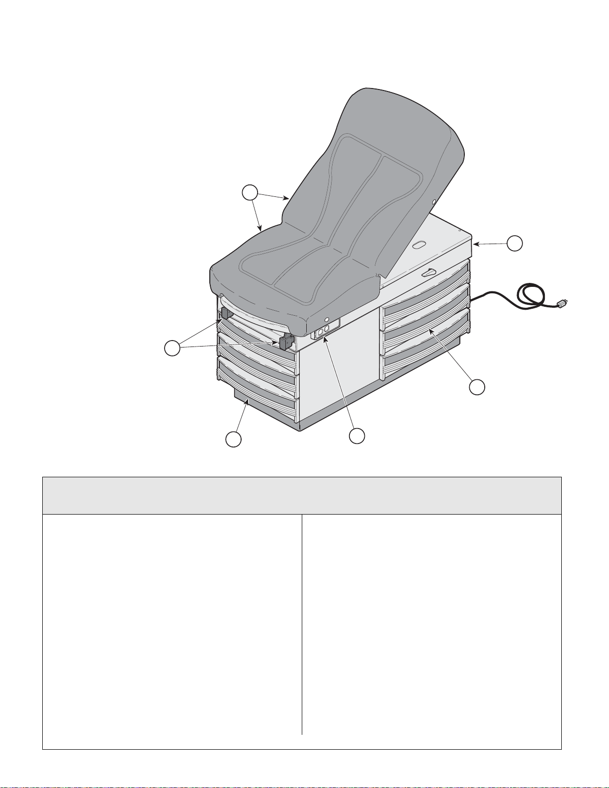
Pictorial Index
1
2
3
5
6
4
Return To Table Of Contents
SECTION VI
PARTS LIS T
MA354000
Used on units with Serial Nu mber JE1000, JF1000, JG1000 & JH1000 thru Present
Used on units with Serial Number V2200 thru Present
Item Part No. Description Page Item Part No. Description Page
304-007-xxx 304 Exam Table - R.H. (110 V.)
304-008-xxx 304 Exam Table - L.H. (110 V.)
304-009-xxx 304 Exam Table - R.H. (110 V.)
304-0010-xxx 304 Exam Table - L.H. (110 V.)
Note: The -xxx in the model number
denotes upholstery color.
Refer to color code chart on this page
with Soft TouchUpholstery
{serial # prefix [JE]}.......................... 6-2.2
with Soft TouchUpholstery
{serial # prefix [JF]}..........................6-2.2
with Soft Touch Upholstery (w/ Heater
& Pelvic Lift) {serial # prefix [JG]} ....6-2.2
with Soft Touch Upholstery (w/ Heater
& Pelvic Lift) {serial # prefix [JH]}..... 6-2.2
Always Specify Model & Serial Number
1 • • Table Top Components .................... 6-4
2 • • Upper Wrap Components................ 6-5
3 • • Stirrup Components......................... 6-6
4 • • Cabinet Components....................... 6-7
5 • • Step Assembly................................. 6-9
6 • • Electrical Components................... 6-10
7 9A01010 Knee Crutch Set.............................. 9A01
8 9A0200* Armboard Assembly........................9A02
9 9A04001 Procto Rest Assembly..................... 9A04
10 9A70000 Stainless Steel Treatment Pan ........... 6-5
11 9A104001 Urology Drain Pan ......................... 9A104
12 9A105002 Pelvic Lift Assembly....................... 9A105
13 9A180002 Welch Allyn Bracket....................... 9A180
14 9A20600* Knee Crutch Set............................ 9A206
15 9A21000* Sideboard Assembly ..................... 9A210
16 9A28100* Welch Allyn Bracket....................... 9A281
Available Accessories
Refer to MEDICAL ACCESSORY BOOK {004-0096-00}
© Midmark Corporation 1999 SF-1532 Printed in U.S.A.
Rev. 3/08
Page 6-2.2
Page 49
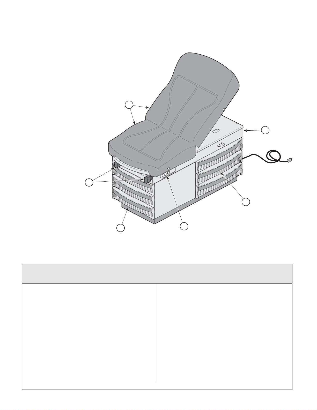
Pictorial Index
Return To Table Of Contents
SECTION VI
PARTS LIS T
1
2
3
4
5
6
MA354000
Used on units with Serial Number LC1000 thru Present
Used on units with Serial Number V2200 thru Present
Item Part No. Description Page Item Part No. Description Page
Note: The -xxx in the model number
denotes upholstery color.
Refer to color code chart on this page
304-015-xxx 304 Exam Table - R.H. Export (220 V.)
with Vacu-Form Upholstery
{serial # prefix [LC]).......................6-2.3
304-016-xxx 304 Exam Table - L.H. Export (220 V.)
with Vacu-Form Upholstery
{serial # prefix [LC]).......................6-2.3
1 • • Table Top Components.....................6-3
2 • • Upper Wrap Components ................6-5
3 • • Stirrup Components .........................6-6
Always Specify Model & Serial Number
4 • • Cabinet Components....................... 6-8
5 • • Step Assembly................................. 6-9
6 • • Electrical Components....................6-11
Available Accessories
Refer to MEDICAL ACCESSORY BOOK {004-0096-00}
9A01010 Knee Crutch Set.............................. 9A01
9A0200* Armboard Assembly........................9A02
9A04001 Procto Rest Assembly..................... 9A04
9A70000 Stainless Steel Treatment Pan ........... 6-5
9A104001 Urology Drain Pan ......................... 9A104
9A105002 Pelvic Lift Accessory ..................... 9A105
9A180002 Welch Allyn Bracket....................... 9A180
9A20600* Knee Crutch Set............................ 9A206
9A21000* Sideboard Assembly ..................... 9A210
9A28100* Welch Allyn Bracket .................... 9A281
© Midmark Corporation 1999 SF-1532 Printed in U.S.A.
Rev. 3/08
Page 6-2.3
Page 50
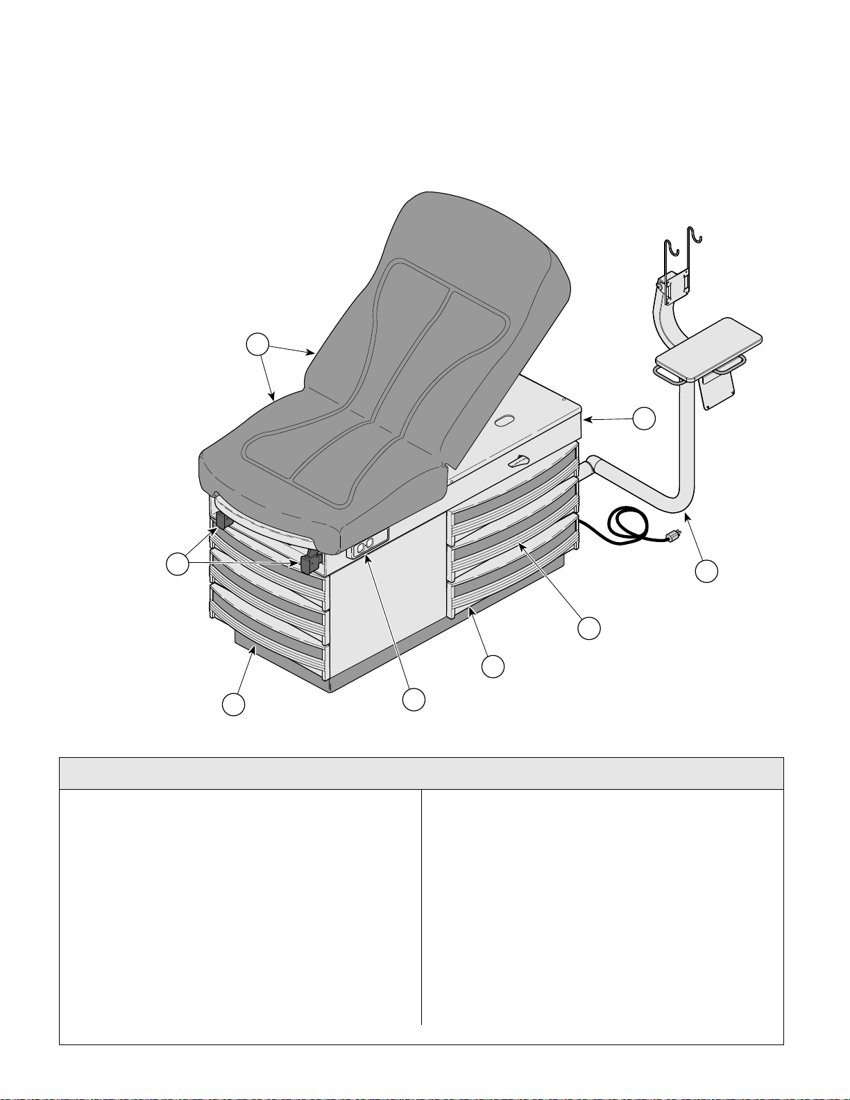
1
2
6
7
4
3
5
8
Pictorial Index
Return To Table Of Contents
SECTION VI
PARTS LIS T
Used on units with Serial Number V2200 thru Present
Item Part No. Description Page Item Part No. Description Page
Note: The -xxx in the model number
denotes upholstery color.
Refer to color code chart on this page
304-017-xxx 304 IPET Exam Table - R.H. (110 V.)
with Vacu-Form Upholstery
{serial # prefix [V]) ...........................6-2.4
1 • • Table Top Components..................6-3.2
2 • • Upper Wrap Components ............. 6-5.2
3 • • Stirrup Components ......................6-6.2
4 • • Cabinet Components .......................6-7
5 • • Step Assembly .................................6-9
6 • • Electrical Components ................6-10.1
7 • • IPET Components..........................6-13
© Midmark Corporation 1999 SF-1532 Printed in U.S.A.
Rev. 3/08
MA681100i
Available Accessories
Refer to MEDICAL ACCESSORY BOOK {004-0096-00}
9A01010 Knee Crutch Set.............................. 9A01
9A0200* Armboard Assembly........................9A02
9A04001 Procto Rest Assembly..................... 9A04
9A70000 Stainless Steel Treatment Pan ........... 6-5
9A104001 Urology Drain Pan ......................... 9A104
9A105002 Pelvic Lift Accessory ..................... 9A105
9A180002 Welch Allyn Bracket....................... 9A180
9A20600* Knee Crutch Set............................ 9A206
9A21000* Sideboard Assembly ..................... 9A210
Always Specify Model & Serial Number
Page 6-2.4
9A28100* Welch Allyn Bracket.......................9A281
Page 51
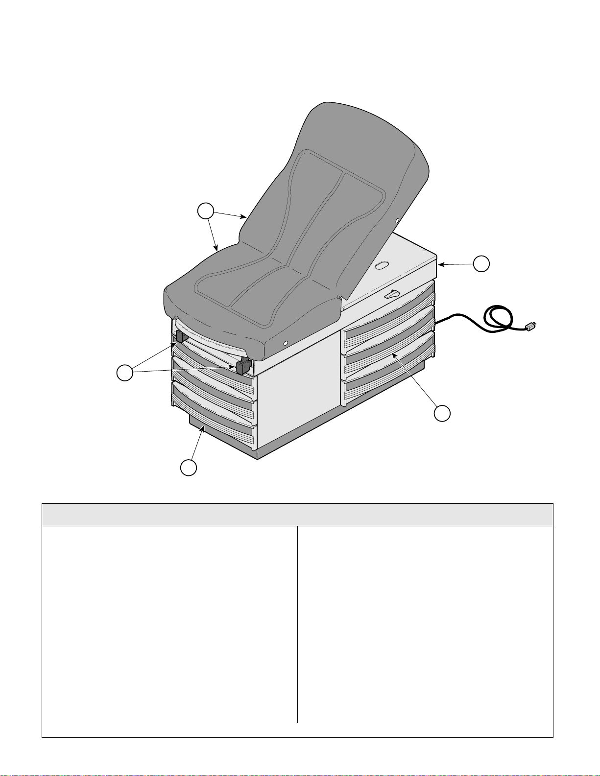
1
2
3
5
4
Pictorial Index
Return To Table Of Contents
SECTION VI
PARTS LIS T
Item Part No. Description Page Item Part No. Description Page
304-018-xxx Canadian 304 Exam Table - R.H. (110 V.)
304-019-xxx Canadian 304 Exam Table - L.H. (110 V.)
304-020-xxx Canadian 304 Exam Table - R.H. (110 V.)
304-0021-xxx Canadian 304 Exam Table - L.H. (110 V.)
1 • • Table Top Components.....................6-4
2 • • Upper Wrap Components ................6-5
3 • • Stirrup Components .........................6-6
© Midmark Corporation 1999 SF-1532 Printed in U.S.A.
Used on units with Serial Number V2200 thru Present
Note: The -xxx in the model number
denotes upholstery color.
Refer to color code chart on this page
with Soft TouchUpholstery ..............6-2.5
with Soft TouchUpholstery ..............6-2.5
w/ Soft Touch Upholstery
(w/Pelvic Lift)....................................6-2.5
with Soft Touch Upholstery
(w/ Pelvic Lift) ..................................6-2.5
Rev. 3/08
4 • • Cabinet Components....................... 6-7
5 • • Step Assembly................................. 6-9
9A01010 Knee Crutch Set.............................. 9A01
9A0200* Armboard Assembly........................9A02
9A04001 Procto Rest Assembly..................... 9A04
9A70000 Stainless Steel Treatment Pan ........... 6-5
9A104001 Urology Drain Pan ......................... 9A104
9A105002 Pelvic Lift Accessory ..................... 9A105
9A180002 Welch Allyn Bracket....................... 9A180
9A20600* Knee Crutch Set............................ 9A206
9A21000* Sideboard Assembly ..................... 9A210
9A28100* Welch Allyn Bracket.......................9A281
Refer to MEDICAL ACCESSORY BOOK {004-0096-00}
Always Specify Model & Serial Number
Page 6-2.5
MA354000
Available Accessories
Page 52
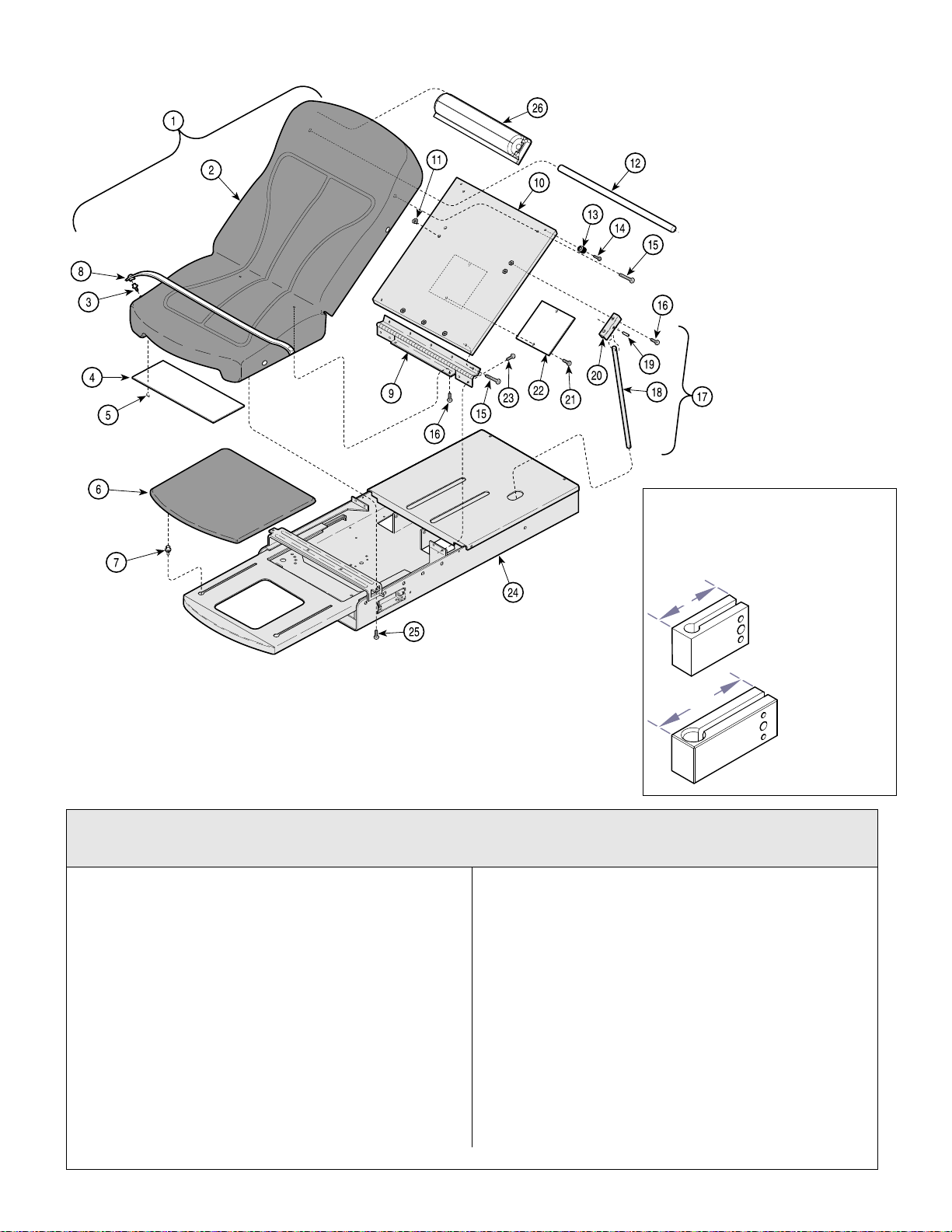
MA618700
3.6 in.
(9.2 cm)
2.6 in.
(6.6 cm)
Table Top Components (Vacu-Form)
Return To Table Of Contents
Color Selector......www.midmark.com
SECTION VI
PARTS LIS T
NOTE
Vacu-Form Uph. Kit (002-0570-00) is no
longer available. Replace this number
with 002-0740-00 (specify color).
MA351203i
Used on units with Serial Number GJ1000 thru GJ7229, GK1000 thru GK10609
If table has knee
crutches, measure
mounting block
before ordering
uph. top.
If mounting block
is less than 3.6 in.
(9.2 cm) long, you
must also order
the Extended
Knee Crutch
Bracket Kit
(002-0517-00).
and LC1000 thru LC2295
Item Part No. Description Page Item Part No. Description Page
1 002-0570-00 Vacu-Form Upholstery Kit - See NOTE
(includes items 2 thru 5)
2 • n/a • Upholstered Top.................................. 1
3 • 016-0022-00 • Stud ....................................................4
4 • 053-0950-00 • Scuff Plate ........................................... 1
5 • 042-0040-00 • Staple ................................................ 10
6 028-0439-00 Upholstered Footrest (specify color) .... 1
7 053-0424-00 Footrest glide ......................................... 4
8 029-0017-00 Paper Tear Strip ..................................... 2
9 016-0715-41 Hinge ..................................................... 1
10 029-1968-00 Back Board Assembly............................1
11 041-0013-00 T Nut (Used on L.H. Units Only)............ 2
12 055-0005-04 Dowel .....................................................1
13 053-0024-00 Recess Bumper ..................................... 2
14 040-0008-95 Screw .....................................................2
Always Specify Model & Serial Number
15 042-0170-40 Winghead Screw ................................... 4
16 040-0010-01 Screw .................................................... 9
17 029-0151-03 Back Support Rod Assembly
(includes 18 thru 20)........................... 1
18 • 057-0013-00 • Back Support Rod1
19 • 042-0001-01 • Roll Pin ............................................... 1
20 • 050-0556-40 • Back Support Bracket ......................... 1
21 040-0006-26 Screw .................................................... 2
22 050-0194-00 Plate...................................................... 1
23 040-0010-35 Screw .................................................... 4
24 Upper Wrap (Refer to “Upper Wrap
Assembly”).......................................Ref
25 040-0010-01 Thumb Screw ........................................ 2
26 053-0852-00 Paper Roll Holder .................................. 1
© Midmark Corporation 1999 SF-1532 Printed in U.S.A.
Rev. 3/08
Page 6-3
Page 53
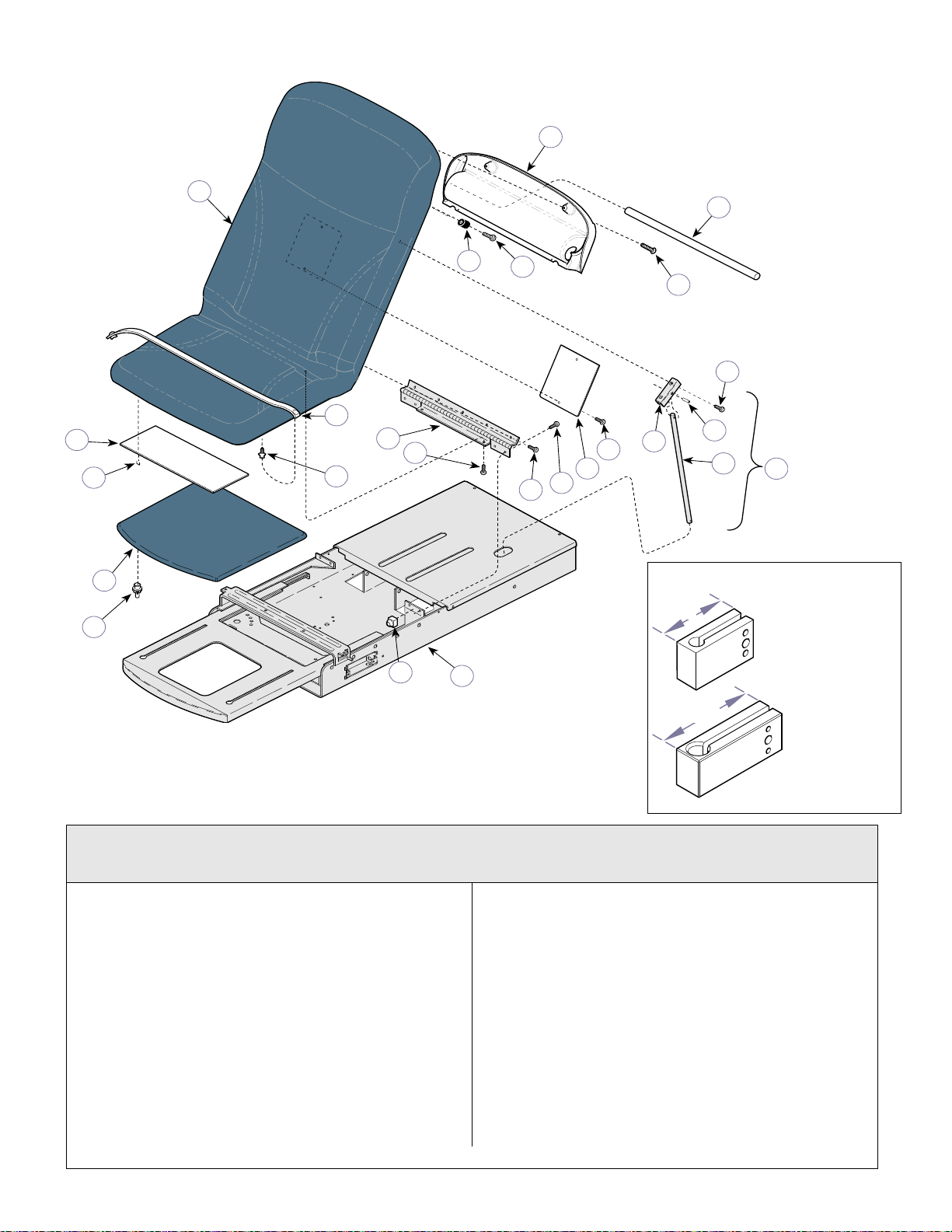
5
1
7
22
18
20
21
23
11
10
13
12
8
3
4
2
5
6
9
16
17
19
14
24
15
Table Top Components (Vacu-Form)
MA618700
3.6 in.
(9.2 cm)
2.6 in.
(6.6 cm)
Return To Table Of Contents
Color Selector......www.midmark.com
SECTION VI
PARTS LIS T
NOTE
If table has knee
MA483805i
crutches, measure
mounting block
before ordering
uph. top.
If mounting block
is less than 3.6 in.
(9.2 cm) long, you
must also order
the Extended
Knee Crutch
Bracket Kit
(002-0517-00).
Used on units with Serial Number GJ7230 thru GJ8849, GK10610 thru GK14082
and LC2296 thru LC2462
Item Part No. Description Page Item Part No. Description Page
1 002-0740-xxx Vacu-Form Upholstery Top
2 • 053-1319-01 • Paper Roll Holder ................................ 1
3 • 040-0008-46 • Screw .................................................. 4
4 • 016-0922-00 • Hinge ...................................................1
5 • 040-0250-03 • Screw .................................................. 7
6 • 053-1290-00 • Recess Bumper................................... 2
7 • 040-0008-104 • Screw .................................................. 2
8 055-0005-07 Dowel .....................................................1
9 053-0950-00 Scuff Plate ............................................. 1
10 042-0040-00 Staple.................................................. AR
11 016-0022-00 Stud .......................................................4
12 028-0439-00 Upholstered Footrest (specify color).... 1
© Midmark Corporation 1999 SF-1532 Printed in U.S.A.
(includes items 2 thru 7)
(replace -xxx w/color code) .............. 1
Always Specify Model & Serial Number
Rev. 3/08
Page 6-3.1
13 053-0424-00 Footrest Glide........................................ 2
14 029-0017-00 Paper Tear Strap ................................... 2
15 053-0014-00 Bumper.................................................. 2
16 040-0010-01 Screw .................................................... 7
17 029-0151-03 Back Support Rod Assembly
18 • 042-0001-01 • Roll Pin ............................................... 1
19 • 057-0013-00 • Back Support Rod .............................. 1
20 • 050-0556-40 • Back Support Bracket ......................... 1
21 040-0006-26 Screw .................................................... 2
22 050-0194-00 Plate...................................................... 1
23 040-0010-35 Screw .................................................... 4
24 Refer to “Upper Wrap Assembly” ....... Ref
(includes items 18 thru 20) ................. 1
Page 54
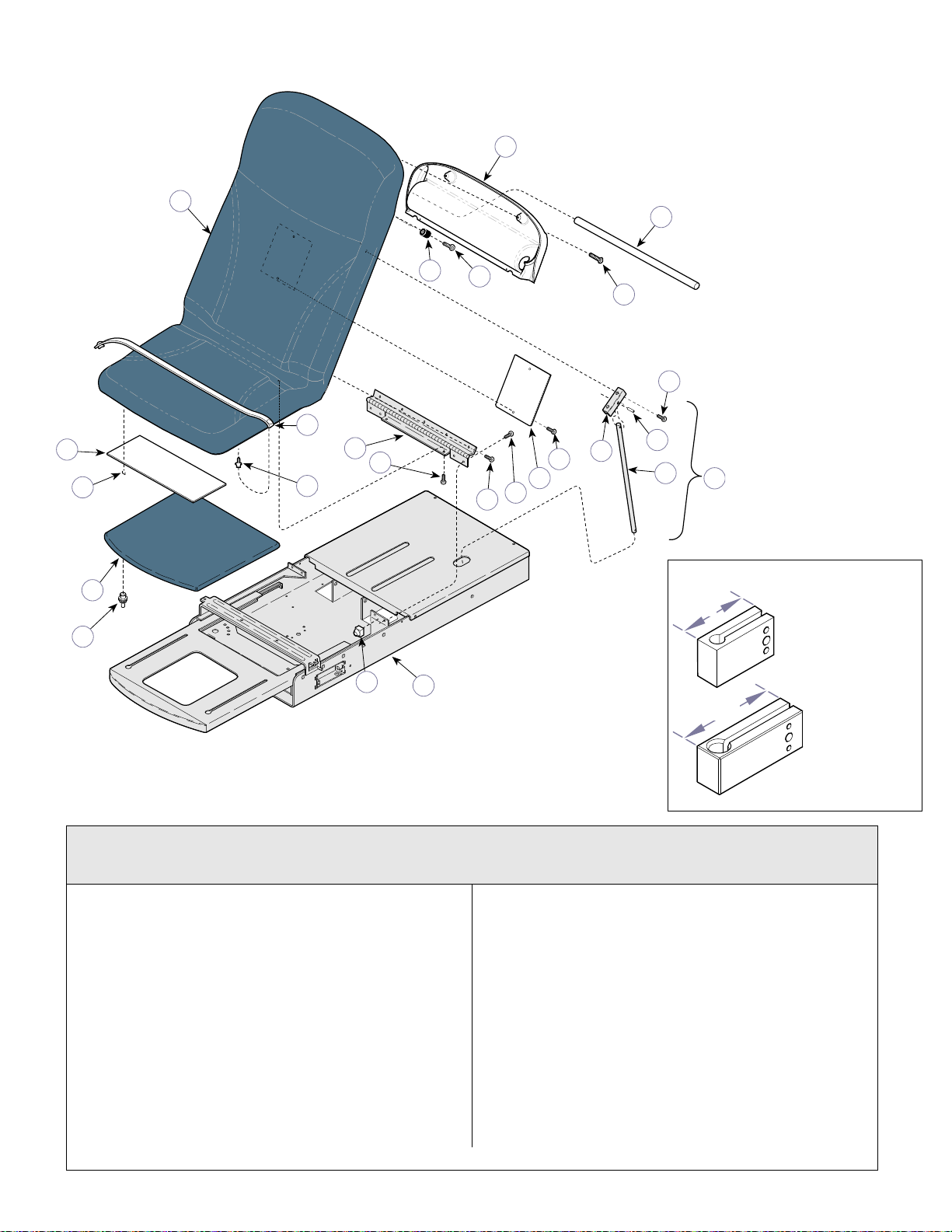
5
1
7
22
18
20
21
23
11
10
13
12
8
3
4
2
5
6
9
16
17
19
14
24
15
Table Top Components (Vacu-Form)
MA618700
3.6 in.
(9.2 cm)
2.6 in.
(6.6 cm)
Return To Table Of Contents
Color Selector......www.midmark.com
SECTION VI
PARTS LIS T
NOTE
If table has knee
crutches, measure
MA4838005i
mounting block
before ordering
uph. top.
If mounting block
is less than 3.6 in.
(9.2 cm) long, you
must also order
the Extended
Knee Crutch
Bracket Kit
(002-0517-00).
Used on units with Serial Number GJ8850, GK14083 & LC2463 thru Present
Used on units with Serial Number V2200 thru Present
Item Part No. Description Page Item Part No. Description Page
1 002-0740-xxx Vacu-Form Upholstery Top
2 • 053-1448-01 • Paper Roll Holder ................................ 1
3 • 040-0008-46 • Screw .................................................. 4
4 • 016-0922-00 • Hinge ...................................................1
5 • 040-0250-03 • Screw .................................................. 7
6 • 053-1290-00 • Recess Bumper................................... 2
7 • 040-0008-104 • Screw .................................................. 2
8 055-0005-08 Dowel .....................................................1
9 053-0950-00 Scuff Plate ............................................. 1
10 042-0040-00 Staple.................................................. AR
11 016-0022-00 Stud .......................................................4
12 028-0439-00 Upholstered Footrest (specify color).... 1
© Midmark Corporation 1999 SF-1532 Printed in U.S.A.
(includes items 2 thru 7)
(replace -xxx w/color code) .............. 1
Always Specify Model & Serial Number
Rev. 3/08
Page 6-3.2
13 053-0424-00 Footrest Glide........................................ 2
14 029-0017-00 Paper Tear Strap ................................... 2
15 053-0014-00 Bumper.................................................. 2
16 040-0010-01 Screw .................................................... 7
17 029-0151-03 Back Support Rod Assembly
18 • 042-0001-01 • Roll Pin ............................................... 1
19 • 057-0013-00 • Back Support Rod .............................. 1
20 • 050-0556-40 • Back Support Bracket ......................... 1
21 040-0006-26 Screw .................................................... 2
22 050-0194-00 Plate...................................................... 1
23 040-0010-35 Screw .................................................... 4
24 Refer to “Upper Wrap Assembly” ....... Ref
(includes items 18 thru 20) ................. 1
Page 55
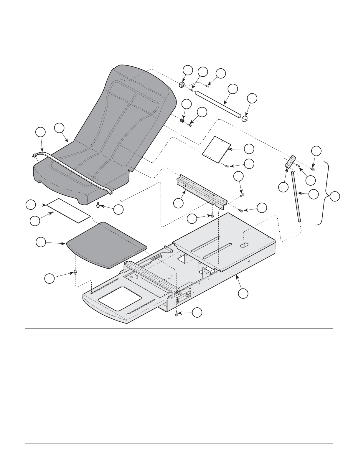
Table Top Components (Soft Touch)
2
3
4
16
5
6
9
9
3
17
9
10
11
15
13
14
23
18
19
20
21
12
24
25
1
14
22
Return To Table Of Contents
Color Selector......www.midmark.com
SECTION VI
PARTS LIS T
Item Part No. Description Page Item Part No. Description Page
1 002-0598-00 Soft Touch Upholstery (Includes Items
2 thru 14 [Specify Color]).......................1
2 • 053-0043-04 • R.H. Pole Socket ................................. 1
3 • 040-0006-26 • Screw .................................................. 4
4 • 042-0605-00 • Wire Nail.............................................. 2
5 • 053-0043-03 • L.H. Pole Socket.................................. 1
6 • 053-0024-00 • Recess Bumper................................... 2
7 • 040-0008-95 • Screw .................................................. 2
8 • 050-0194-00 • Plate .................................................... 4
9 • 040-0006-26 • Screw .................................................. 4
10 • 053-0950-00 • Scuff Plate (Used w/ Pelvic Lift Only).. 1
11 • 042-0040-00 • Staple (Used w/ Pelvic Lift Only) .......10
12 • 016-0715-41 • Hinge ................................................... 1
13 • 053-0424-00 • Footrest glide ......................................4
14 • 040-0010-01 • Screw .................................................. 7
Always Specify Model & Serial Number
15 028-0439-00 Upholstered Footrest (Specify Color) .... 1
16 055-0005-00 Dowel .................................................... 1
17 029-0017-00 Paper Tear Strip .................................... 2
18 029-0151-03 Back Support Rod Assembly (Includes
19 • 057-0013-00 • Back Support Rod .............................. 1
20 • 042-0001-01 • Roll Pin ............................................... 1
21 • 050-0556-40 • Back Support Bracket ......................... 1
22 040-0010-35 Screw .................................................... 4
23 040-0010-01 Screw .................................................... 2
24 Upper Wrap (Refer to “Upper Wrap
25 040-0010-01 Screw (Non Pelvic Lift Units Only) ...... 2
19 thru 21)............................................. 1
Assembly” Elsewhere)........................ Ref
MA420301
© Midmark Corporation 1999 SF-1532 Printed in U.S.A.
Rev. 3/08
Page 6-4
Page 56
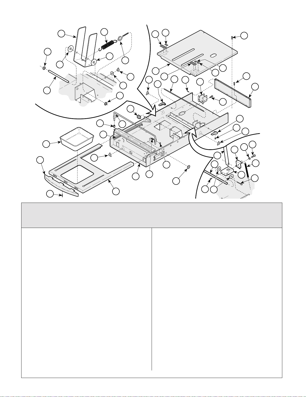
27
21
23
22
24
25
26
28
29
2
Upper Wrap Components
Return To Table Of Contents
SECTION VI
PARTS LIS T
32
33
4
5
10
11
39
1
2
6
2
9
18
12
29
16
15
8
42
7
3
41
40
13
14
1
13
17
19
36
35
37
20
42
42
34
38
30
43
16
Used on units with Serial Number GJ1000 thru GJ4377, GK1000 thru GK6755,
GL1000 thru GLxxxx, JE1000 thru JE1348, JF1000 thru JF1094, JG1000 thru JG2278,
Item Part No. Description Page Item Part No. Description Page
1 042-0159-00 Retaining Ring ....................................... 2
2 045-0001-01 Washer ..................................................4
3 057-0436-00 Lift Support Rod..................................... 1
4 051-0132-40 Lift Lever ................................................ 1
5 025-0003-00 Lift Spring .............................................. 2
6 016-0008-00 Eye Bolt ................................................. 2
7 045-0001-02 Washer ..................................................2
8 041-0250-05 Wing Nut ................................................ 2
9 029-0305-06 Cover Assy. (Right Hand Tables Only .... 1
029-0305-07 Cover Assy. (Left Hand Tables Only ...... 1
10 Serial Number Label.......................... Ref
11 061-0291-00 Patent Number Label ............................. 1
12 061-0620-00 U.L./C.U.L. Label(Domestic Units)......... 1
061-0661-00 CE Representative Label (Export Units) 1
13 040-0010-00 Screw ...................................................12
14 050-0180-40 End Cap.................................................1
15 050-1651-40 Lock Bracket (Left Hand Tables Only) ... 1
16 042-0010-03 Pop Rivet ...............................................4
17 053-0014-00 Self Sticking Bumper ............................. 4
18 053-0844-00 R.H. Back Lock Handle..........................1
19 053-0844-01 L.H. Back Lock Handle .......................... 1
20 040-0250-148 Set Screw .............................................. 2
21 040-0010-74 Screw .....................................................1
22 045-0001-04 Lockwasher............................................ 1
23 050-0101-00 Back Lock Spring Retainer .................... 1
© Midmark Corporation 1999 SF-1532 Printed in U.S.A.
Rev. 10/01
31
MA354101
JH1000 thru JH1217 & LC1000 thru LC1694
24 025-0008-00 Back Lock Spring .................................. 2
25 051-0002-00 Back Lock .............................................. 1
26 042-0003-00 Cotter Pin .............................................. 1
27 Back Support Rod Assembly (Refer to
Table Top Components” Elsewhere) ..Ref
28 040-0250-00 Set Screw .............................................. 2
29 057-0435-40 Back Lock Rod ...................................... 1
30 030-0731-40 Upper Wrap Weldment.......................... 1
31 030-1034-40 Foot Rest Weldment.............................. 1
32 053-0828-00 Foot Rest Trim....................................... 1
33 053-0220-01 Treatment Pan (Standard)..................... 1
9A70000 Stainless Steel Treatment Pan
(Optional Accessory)............................. 1
34 041-0009-00 Push Nut ............................................... 2
35 053-0018-00 Nylon Tape (Listed In Inches).............. 52
36 053-0268-00 End Cap (Units w/ Pelvic Lift Only) ....... 2
37 057-0242-40 Pelvic Lift Bar (Units w/ Pelvic Lift Only) 1
38 016-0284-01 R.H. Spring (Units on Left Side[Shown]) 1
016-0284-00 L.H. Spring (Units on Left Side) ............ 1
39 040-0010-18 Screw .................................................... 4
40 061-0652-00 Type B Equipment Label (Export Units) 1
41 061-0590-00 CE Label (Export Units) ........................ 1
42 061-0654-00 Caution Label(Export Units).................. 3
43 061-0653-00 Earth (Ground) Label (Export Units)... 1
Always Specify Model & Serial Number
Page 6-5
Page 57
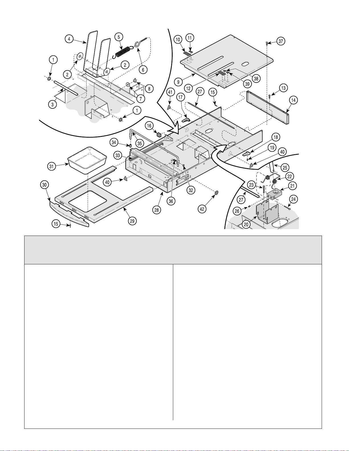
Upper Wrap Components
Return To Table Of Contents
SECTION VI
PARTS LIS T
MA354102
Used on units with Serial Number GJ4378 thru GJ8690, GK6756 thru GK13746,
GLxxxx thru GLxxxx, JE1349 thru JE1645, JF1095 thru JF1217, JG2279 thru JG3105,
JH1218 thru JH1417 & LC1695 thru LC2452
Item Part No. Description Page Item Part No. Description Page
1 042-0159-00 Retaining Ring ....................................... 2
2 045-0001-01 Washer ..................................................2
3 057-0436-00 Lift Support Rod..................................... 1
4 051-0132-40 Lift Lever ................................................ 1
5 025-0003-00 Lift Spring .............................................. 2
6 016-0008-00 Eye Bolt ................................................. 2
7 045-0001-02 Washer ..................................................2
8 041-0250-05 Wing Nut ................................................ 2
9 029-0305-06 Cover Assy. (Right Hand Tables Only .... 1
029-0305-07 Cover Assy. (Left Hand Tables Only ...... 1
10 Serial Number Label.......................... Ref
11 061-0291-00 Patent Number Label ............................. 1
12 061-0620-00 U.L./C.U.L. Label(Domestic Units)......... 1
061-0661-00 CE Representative Label (Export Units) 1
13 040-0010-00 Screw ...................................................14
14 050-0180-40 End Cap.................................................1
15 042-0010-03 Pop Rivet ...............................................4
16 053-0014-00 Self Sticking Bumper ............................. 4
17 053-0844-00 R.H. Back Lock Handle..........................1
18 053-0844-01 L.H. Back Lock Handle .......................... 1
19 040-0250-148 Set Screw .............................................. 2
20 050-4723-40 Back Lock Spring Retainer .................... 1
21 051-0926-00 Back Lock ..............................................1
22 025-0063-00 Back Lock Spring ................................... 2
Always Specify Model & Serial Number
23 Screw .................................................... 2
24 042-0003-00 Cotter Pin .............................................. 1
25 Back Support Rod Assembly (Refer to
Table Top Components” Elsewhere) ..Ref
26 040-0250-00 Set Screw .............................................. 2
27 057-0435-40 Back Lock Rod ...................................... 1
28 030-1286-40 Upper Wrap Weldment.......................... 1
29 030-1034-40 Foot Rest Weldment.............................. 1
30 053-0828-00 Foot Rest Trim....................................... 1
31 053-0220-01 Treatment Pan (Standard)..................... 1
9A70000 Stainless Steel Treatment Pan
(Optional Accessory)............................. 1
32 041-0009-00 Push Nut ............................................... 2
33 053-0018-00 Nylon Tape (Listed In Inches).............. 52
34 053-0268-00 End Cap (Units w/ Pelvic Lift Only) ....... 2
35 057-0242-40 Pelvic Lift Bar (Units w/ Pelvic Lift Only) 1
36 016-0284-01 R.H. Spring (Units on Left Side[Shown]) 1
016-0284-00 L.H. Spring (Units on Left Side) ............ 1
37 040-0010-18 Screw .................................................... 4
38 061-0652-00 Type B Equipment Label (Export Units) 1
39 061-0590-00 CE Label (Export Units) ........................ 1
40 ddd ....................................................... 1
41 061-0654-00 Caution Label(Export Units).................. 3
42 061-0653-00 Earth (Ground) Label (Export Units) ..... 1
© Midmark Corporation 1999 SF-1532 Printed in U.S.A.
Rev. 9/03
Page 6-5.1
Page 58
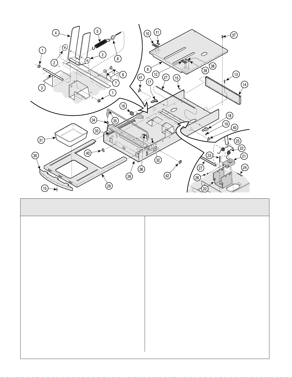
Upper Wrap Components
Return To Table Of Contents
SECTION VI
PARTS LIST
MA354102
Used on units with Serial Number GJ8691, GK13747, GL1232, JE1646, JF1218,
JG3106, JH1418 LC2453 & V2200 thru Present
Item Part No. Description Page Item Part No. Description Page
1 042-0159-00 Retaining Ring ....................................... 2
2 045-0001-01 Washer ..................................................2
3 057-0436-00 Lift Support Rod..................................... 1
4 051-0132-40 Lift Lever ................................................ 1
5 025-0003-00 Lift Spring .............................................. 2
6 016-0008-00 Eye Bolt ................................................. 2
7 045-0001-02 Washer ..................................................2
8 041-0250-05 Wing Nut ................................................ 2
9 029-0305-06 Cover Assy. (Right Hand Tables Only .... 1
029-0305-07 Cover Assy. (Left Hand Tables Only ...... 1
10 Serial Number Label.......................... Ref
11 061-0291-00 Patent Number Label ............................. 1
12 Regulatory Compliance Label (Dom.) Ref
061-0661-00 CE Representative Label (Export).........1
13 040-0010-00 Screw ...................................................14
14 050-0180-40 End Cap (without holes {shown})........... 1
050-0180-41 End Cap (with circuit breaker holes) ...... 1
15 042-0010-03 Pop Rivet ...............................................4
16 053-0014-00 Self Sticking Bumper ............................. 4
17 053-0844-00 R.H. Back Lock Handle..........................1
18 053-0844-01 L.H. Back Lock Handle .......................... 1
19 040-0250-148 Set Screw .............................................. 2
20 050-4723-40 Back Lock Spring Retainer .................... 1
21 051-0926-00 Back Lock ..............................................1
22 025-0063-00 Back Lock Spring ................................... 2
Always Specify Model & Serial Number
23 Screw .................................................... 2
24 042-0003-00 Cotter Pin .............................................. 1
25 Back Support Rod Assembly (Refer to
Table Top Components” Elsewhere) ..Ref
26 040-0250-00 Set Screw .............................................. 2
27 057-0435-40 Back Lock Rod ...................................... 1
28 030-1498-40 Upper Wrap Weldment.......................... 1
29 030-1034-40 Foot Rest Weldment.............................. 1
30 053-0828-00 Foot Rest Trim....................................... 1
31 053-0220-01 Treatment Pan (Standard)..................... 1
9A70000 Stainless Steel Treatment Pan
(Optional Accessory)............................. 1
32 041-0009-00 Push Nut ............................................... 2
33 053-0018-00 Nylon Tape (Listed In Inches).............. 52
34 053-0268-00 End Cap (Units w/ Pelvic Lift Only) ....... 2
35 057-0242-40 Pelvic Lift Bar (Units w/ Pelvic Lift Only) 1
36 016-0284-01 R.H. Spring (Units on Left Side[Shown]) 1
016-0284-00 L.H. Spring (Units on Left Side) ............ 1
37 040-0010-18 Screw .................................................... 4
38 061-0652-00 Type B Equipment Label (Export Units) 1
39 061-0590-00 CE Label (Export Units) ........................ 1
40 ddd ....................................................... 1
41 061-0654-00 Caution Label(Export Units).................. 3
42 061-0653-00 Earth (Ground) Label (Export Units) ..... 1
© Midmark Corporation 1999 SF-1532 Printed in U.S.A.
Rev. 1/05
Page 6-5.2
Page 59
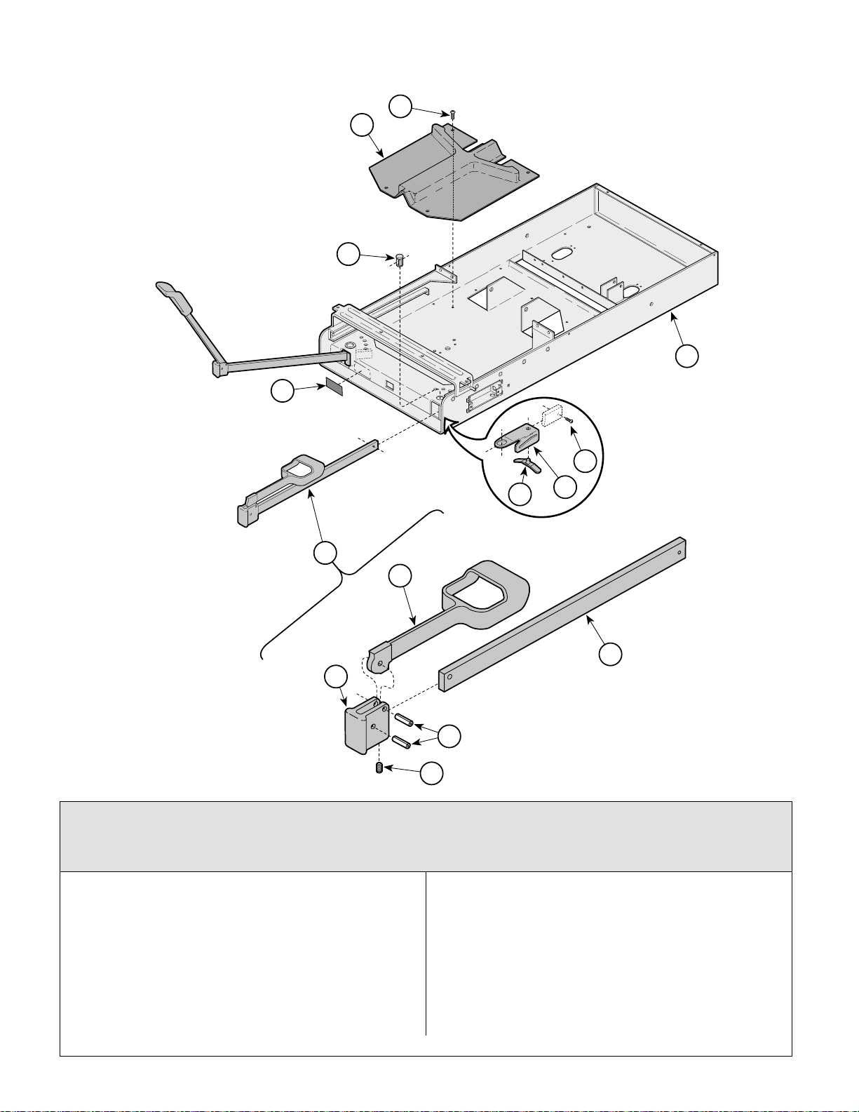
Stirrup Components
Return To Table Of Contents
10
14
SECTION VI
PARTS LIS T
12
11
13
9
8
This assembly is no longer
available. It has been re-
7
1
2
placed by 002-0719-05.
Note: This kit contains only
one stirrup.
6
3
4
5
Used on units with Serial Number GJ1000 thru GJ4377, GK1000 thru GK6755,
GL1000 thru GL1231, JE1000 thru JE1348, JF1000 thru JF1094, JG1000 thru JG2278,
JH1000 thru JH1217 & LC1000 thru LC1694
MA354200i
Item Part No. Description Page Item Part No. Description Page
1 029-1397-02 Stirrup Assembly (Includes
Items 2 thru 6) .......................................2
2 • 020-0181-30 • Stirrup..................................................1
3 • 020-0182-30 • Pivot Block...........................................1
4 • 042-0001-00 • Roll Pin................................................ 2
5 • 040-0250-15 • Set Screw............................................ 1
6 • 051-0668-03 • Horizontal Bar .....................................1
7 016-0400-00 Stirrup Index Spring (Apply Lubricant
#S006-0719)..........................................2
© Midmark Corporation 1999 SF-1532 Printed in U.S.A.
Rev. 1/03
8 050-1785-02 Stirrup Guide Bracket............................ 2
9 040-0010-47 Screw .................................................... 2
10 053-0387-00 Pivot Boss ............................................. 2
11 053-0380-00 Stirrup Guide......................................... 1
12 040-0010-00 Screw .................................................... 4
13 Upper Wrap (Refer to “Upper Wrap
Assembly” Elsewhere)........................ Ref
14 061-0296-00 Stirrup Label.......................................... 1
Always Specify Model & Serial Number
Page 6-6
Page 60
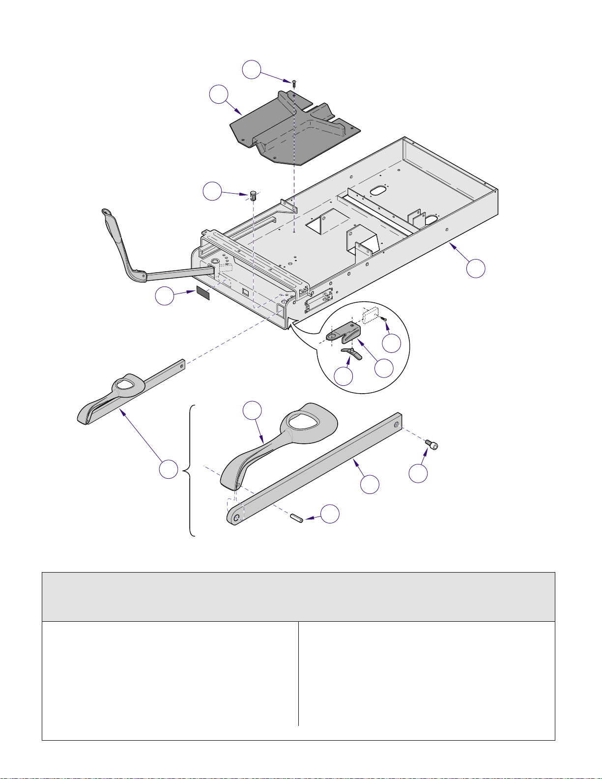
Stirrup Components
Return To Table Of Contents
9
8
14
11
SECTION VI
PARTS LIS T
10
12
5
7
6
2
1
5
4
3
Used on units with Serial Number GJ7244 thru GJ8690, GK10689 thru GK13746,
GL1221 thru GL1231, JE1349 thru JE1645, JF1210 thru JF1217, JG3028 thru JG3105,
JH1400 thru JH1417 & LC2295 thru LC2452
MA605800i
Item Part No. Description Page Item Part No. Description Page
1 029-2951-03 Stirrup Assembly (Includes
Items 2 thru 4) .......................................2
2 • 020-0239-30 • Stirrup..................................................1
3 • 042-0001-00 • Roll Pin................................................ 1
4 • 051-1003-01 • Stirrup Bar ........................................... 1
5 040-0010-47 Screw .....................................................2
6 016-0400-00 Stirrup Index Spring (Apply Lubricant
#S006-0719)..........................................2
© Midmark Corporation 1999 SF-1532 Printed in U.S.A.
Rev. 9/04
7 050-5525-02 Stirrup Guide Bracket............................ 2
8 053-0387-00 Pivot Boss ............................................. 2
9 053-0380-00 Stirrup Guide......................................... 1
10 040-0010-00 Screw .................................................... 4
11 061-0296-00 Stirrup Label.......................................... 1
12 Upper Wrap (Refer to “Upper Wrap
Assembly” Elsewhere)........................ Ref
Always Specify Model & Serial Number
Page 6-6.1
Page 61
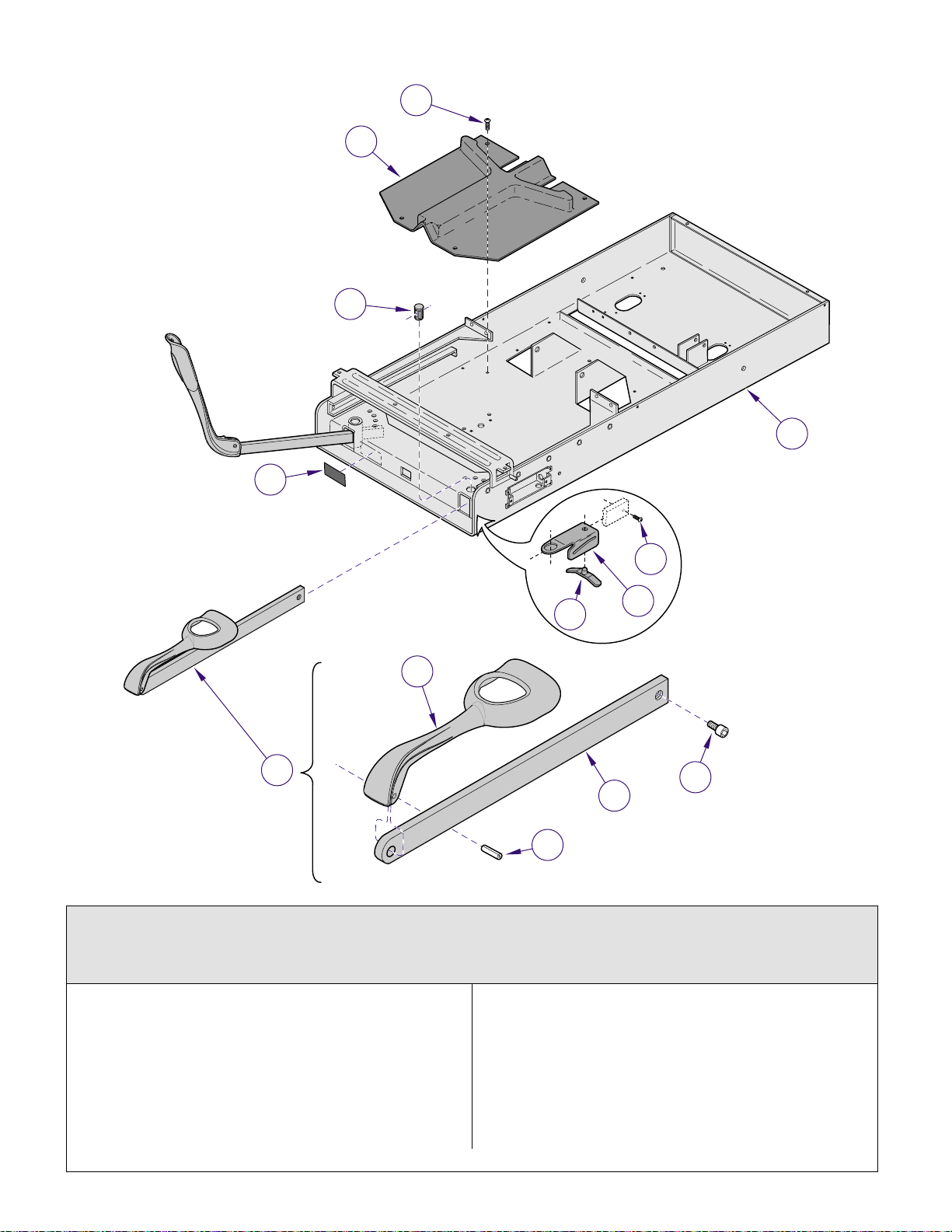
Stirrup Components
Return To Table Of Contents
9
8
14
11
SECTION VI
PARTS LIS T
10
12
5
7
6
2
1
5
4
3
MA605800i
Used on units with Serial Number GJ8691, GK13747, GL1232, E1646, JF1218,
JG3106, JH1418 & LC2453 thru Present
Used on units with Serial Number V2200 thru Present
Item Part No. Description Page Item Part No. Description Page
1 029-2951-03 Stirrup Assembly (Includes
Items 2 thru 4) .......................................2
2 • 020-0239-30 • Stirrup..................................................1
3 • 042-0001-00 • Roll Pin................................................ 1
4 • 051-1003-01 • Stirrup Bar ........................................... 1
5 040-0010-47 Screw .....................................................2
6 016-0400-00 Stirrup Index Spring (Apply Lubricant
#S006-0719)..........................................2
Always Specify Model & Serial Number
7 050-5525-02 Stirrup Guide Bracket............................ 2
8 053-0387-00 Pivot Boss ............................................. 2
9 053-1391-00 Stirrup Guide......................................... 1
10 040-0010-00 Screw .................................................... 4
11 061-0296-00 Stirrup Label.......................................... 1
12 Upper Wrap (Refer to “Upper Wrap
Assembly” Elsewhere) .....................Ref
© Midmark Corporation 1999 SF-1532 Printed in U.S.A.
Rev. 9/04
Page 6-6.2
Page 62
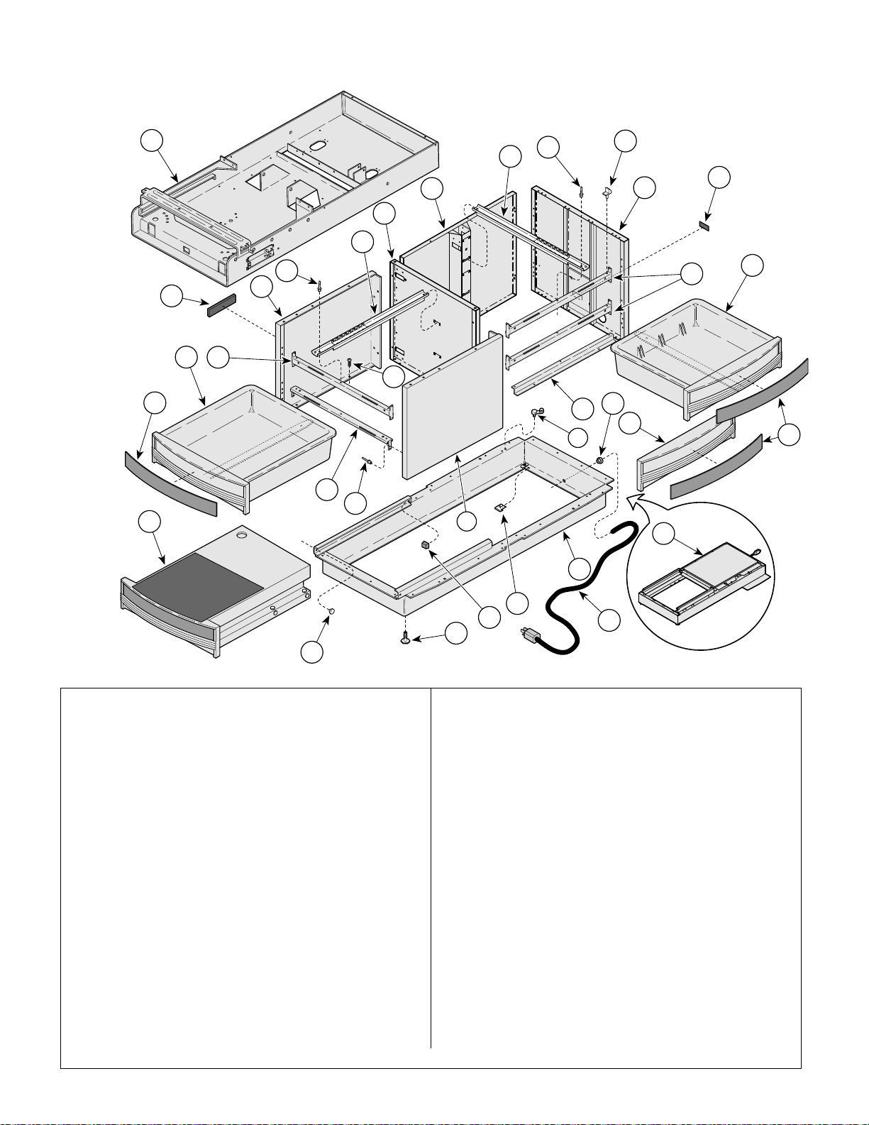
Cabinet Components
Return To Table Of Contents
(120 VAC Units)
SECTION VI
PARTS LIS T
28
1
27
5
9
8
10
11
30
7
6
5
2
26
25
4
12
14
3
17
13
31
18
15
24
23
4
32
19
20
21
16
22
29
MA354501i
Item Part No. Description Page Item Part No. Description Page
1 Upper Wrap (refer to “Upper Wrap
Assembly” elsewhere) ....................... Ref
2 061-0621-02 Nameplate Label.................................... 1
3 040-0010-00 Screw ...................................................18
4 050-3608-40 Front Support Panel............................... 2
5 042-0010-03 Pop Rivet ............................................... 5
6 016-0677-01 Cabinet Member Foot Slide................... 2
7 050-3607-40 Center Support (304-001 thru -016) ......1
050-6139-40 Center Support (304-017 [shown]) ........1
8 030-1035-40 Back Weldment (304-001 thru -016)...... 1
030-1546-40 Back Weldment (304-017 [shown])........1
9 016-0676-01 Side Slide (304-001 thru -016) ..............3
016-0676-01 Side Slide (304-017) ..............................2
10 053-0004-00 Glide .................................................... 10
11 050-3609-40 End Panel (304-001 thru -016) ..............1
030-1428-40 End Panel Weldment (304-017 [shown])1
12 050-3617-40 Side Mullion ........................................... 2
13 050-3715-40 Side Mounting Bracket........................... 1
14 002-0709-04-xxx Side Drawer Assy. (304-001 thru -017
[incl. item 15]) ........................................3
15 • 050-3684-00 • Drawer Insert (specify color) ............... 3
Always Specify Model & Serial Number
16 Power Cord Assembly (refer to
“Electrical Components” elsewhere) ..Ref
17 015-0002-05 Strain Relief Bushing............................. 1
18 015-0007-04 Wrap-N-Tap Wire Clamp ....................... 1
19 030-1059-30 Base Weldment (used only on 304-001
thru 304-016 models [shown])............... 1
030-1540-30 Base Weldment (used only on 304-017)1
20 041-0030-00 Speed Nut ............................................. 2
21 053-0014-00 Self Sticking Bumper............................. 2
22 016-0001-00 Leveling Screw ...................................... 4
23 042-0010-01 Pop Rivet............................................. 18
24 050-3628-40 Short Foot Mullion ................................. 1
25 050-3618-40 Foot Mullion........................................... 1
26 002-0709-05-xxx Drawer Assy.- Foot (incl. item 27) ......... 2
27 • 050-3685-00 • Drawer Insert (specify color)............... 2
28 Step Assembly (refer to
“Step Assembly” elsewhere)) .............Ref
29 053-0001-00 Nylon Stem Bumper .............................. 2
30 061-0295-00 Cord Tag................................................ 1
31 029-3378-00 Drawer Front Assembly (304-017 only) .1
32 IPET Components (refer to “IPET
Components” elsewhere)).................. Ref
© Midmark Corporation 1999 SF-1532 Printed in U.S.A.
Rev. 3/08
Page 6-7
Page 63
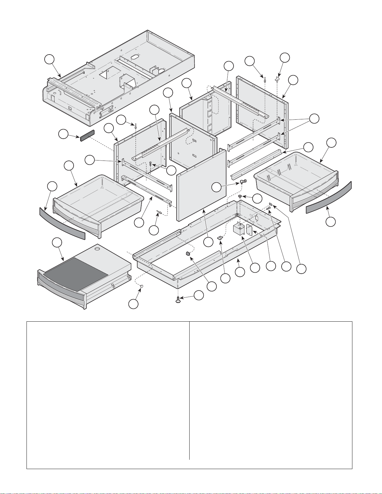
Cabinet Components
Return To Table Of Contents
(220 VAC Units)
SECTION VI
PARTS LIS T
1
27
9
5
8
10
11
7
6
5
12
4
2
13
14
25
26
3
1818
30
24
15
23
28
4
31
19
16
17
32
20
21
22
29
MA482200
Item Part No. Description Page Item Part No. Description Page
1 Upper Wrap (Refer to “Upper Wrap
Assembly” Elsewhere)....................... Ref
2 061-0621-02 Nameplate Label.................................... 1
3 040-0010-00 Screw................................................... 18
4 050-3608-40 Front Support Panel............................... 2
5 042-0010-03 Pop Rivet ............................................... 5
6 016-0677-01 Cabinet Member Foot Slide................... 2
7 050-3607-40 Center Support Panel ............................1
8 030-1035-40 Back Weldment...................................... 1
9 016-0676-01 Cabinet Member Side Slide................... 3
10 053-0004-00 Glide .................................................... 10
11 050-3609-40 End Panel .............................................. 1
12 050-3617-40 Side Mullion ........................................... 2
13 050-3715-40 Side Mounting Bracket........................... 1
14 002-0709-04-xxx Side Drawer Assy. (incl. item 15) ........... 3
15 • 050-3684-00 • Drawer Insert (Specify Color).............. 3
16 050-4153-00 Appliance Inlet Enclosure
(Units w/ Receptacle)............................. 1
17 040-0010-47 Screw..................................................... 2
Always Specify Model & Serial Number
18 015-0007-04 Wrap-N-Tap Wire Clamp ....................... 1
19 030-1158-30 Base Weldment..................................... 1
20 041-0030-00 Speed Nut ............................................. 2
21 053-0014-00 Self Sticking Bumper............................. 2
22 016-0001-00 Leveling Screw ...................................... 4
23 042-0010-01 Pop Rivet............................................. 18
24 050-3628-40 Short Foot Mullion ................................. 1
25 050-3618-40 Foot Mullion........................................... 1
26 002-0709-05-xxx Drawer Assy.- Foot (incl. item 15) ......... 2
27 • 050-3685-00 • Drawer Insert (Specify Color) ............. 2
28 Step Assembly (Refer to
“Step Assembly”) ............................. Ref
29 053-0001-00 Nylon Stem Bumper .............................. 2
30 053-0068-00 Snap Bushing (Units w/ Receptacle)..... 1
31 Appliance Inlet Cover (Units w/o
Receptacle)(Refer to “Receptacle
Assembly [Export]” ................................ 1
32 061-0662-00 Fuse Replacement Label
(Units w/ Receptacle).......................... 1
© Midmark Corporation 1999 SF-1532 Printed in U.S.A.
Rev. 3/08
Page 6-8
Page 64
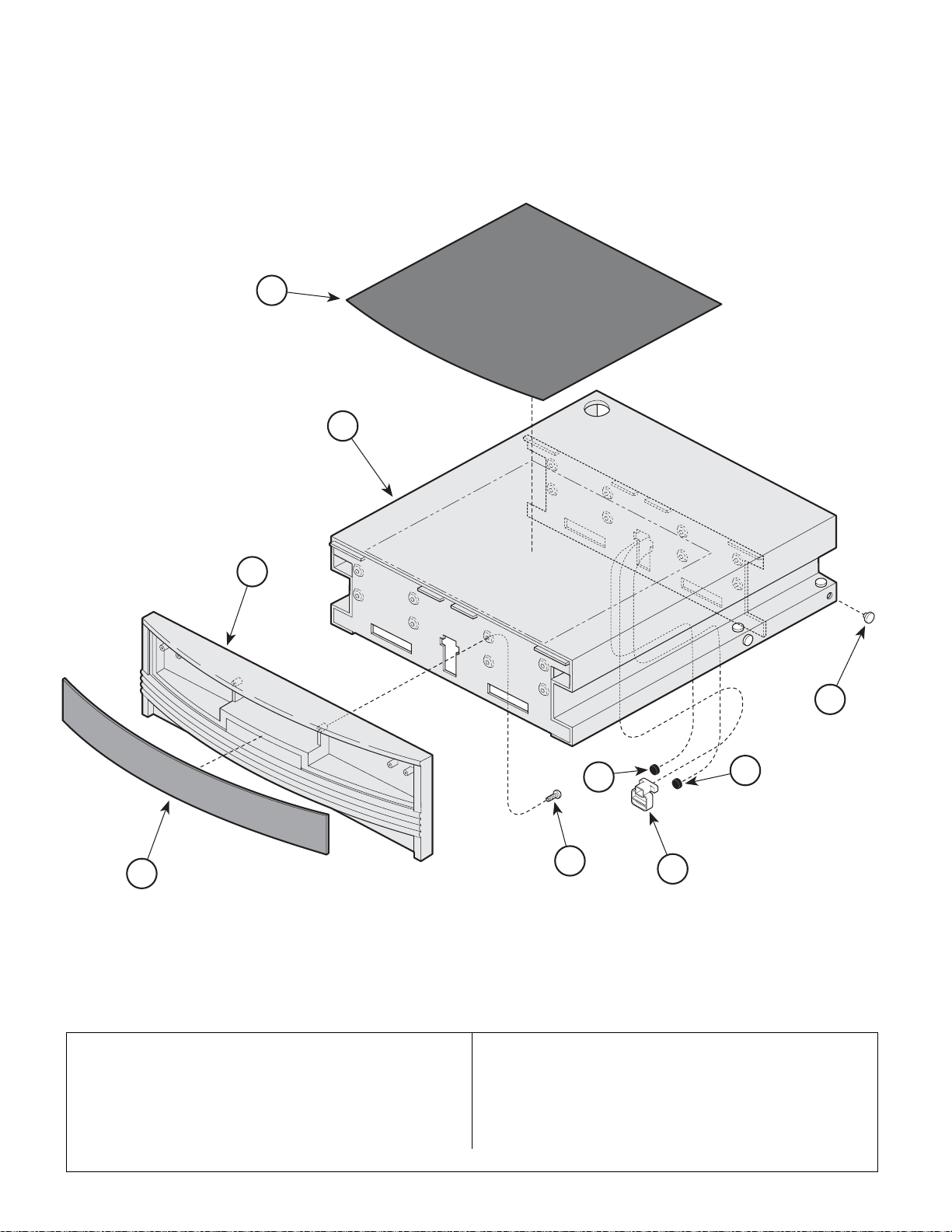
Step Assembly
Return To Table Of Contents
1
SECTION VI
PARTS LIS T
2
3
7
8
4
5
Item Part No. Description Page Item Part No. Description Page
002-0709-06-xxx Step Assembly (incl. #1 thru #8)............1
1 • 053-0848-00 • Step Covering .....................................1
2 • 030-1050-40 • Step Weldment.................................... 1
3 • 053-0823-00 • Foot Drawer Front ............................... 1
4 • 050-3685-00 • Drawer Insert (Specify Color)..............1
Always Specify Model & Serial Number
5 • 040-0006-00 • Screw .................................................. 8
6 • 053-0846-00 • Step Stop............................................ 1
7 • 053-0001-00 • Nylon Stem Bumper.......................... 12
8 • 053-0716-00 • Bumper .............................................. 2
6
8
MA354301
© Midmark Corporation 1999 SF-1532 Printed in U.S.A.
Rev. 3/08
Page 6-9
Page 65
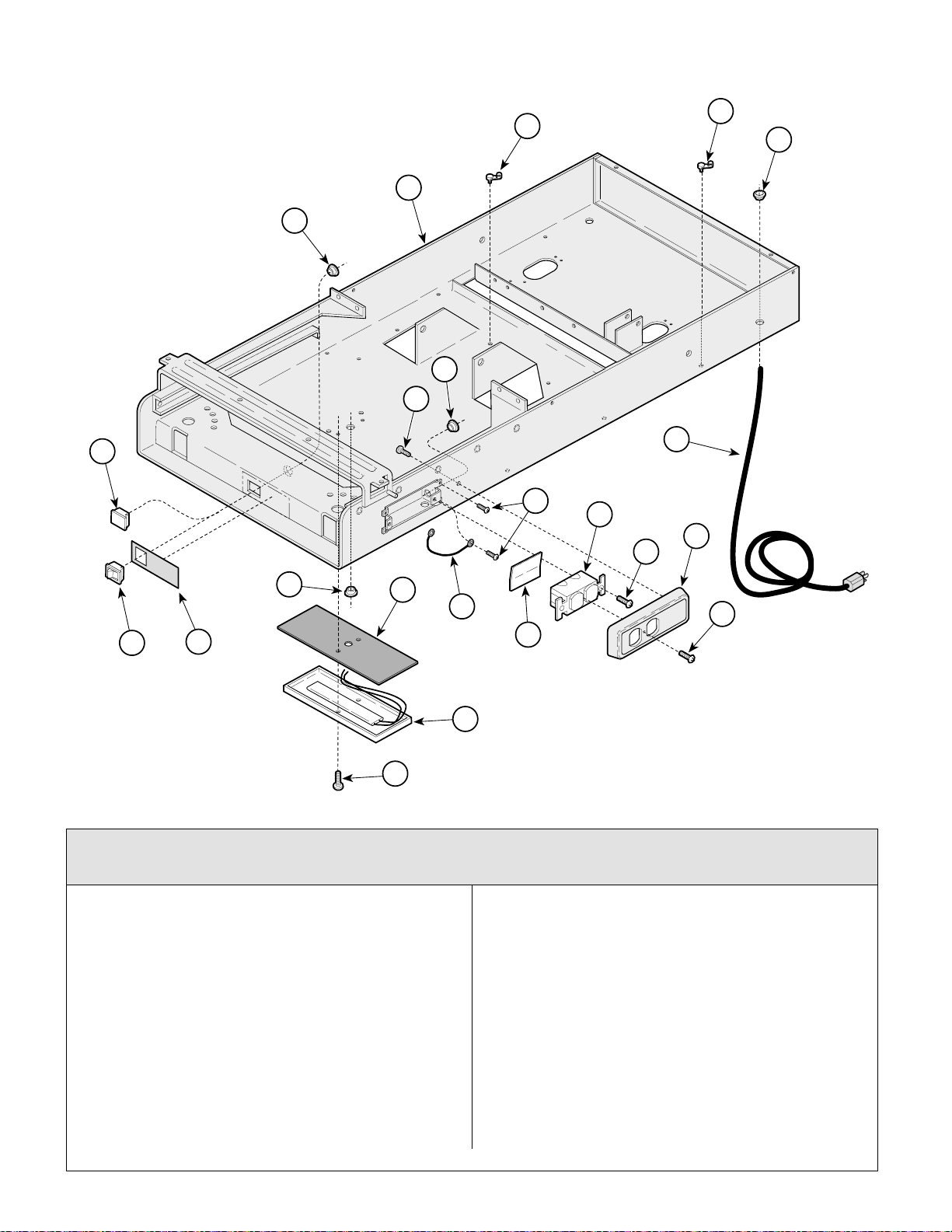
Electrical Components
Return To Table Of Contents
(120 VAC Units)
20
14
5
SECTION VI
PARTS LIS T
1
19
2
4
11
3
5
7
9
8
12
15
13
16
21
10
6
17
18
Used on units with Serial Number GJ1000 thru GJ8690, GK1000 thru GK13746,
JE1000 thru JE1645, JF1000 thru JF1217, JG1000 thru JG3105 & JH1000 thru JH1417
MA354400
Item Part No. Description Page Item Part No. Description Page
1 015-0007-04 Wrap-N-Tap Wire Clamp........................3
2 053-0068-00 Snap Bushing ........................................1
3 015-0066-03 Power Cord Assembly ...........................1
4 053-0068-07 Snap Bushing ........................................1
5 040-0010-47 Screw..................................................... 3
6 053-0092-00 Fishpaper Insulator................................ 1
7 015-0083-01 Duplex Receptacle (Refer to “Wiring
Diagram [Section 5] for Wire Numbers ..1
8 040-0006-13 Screw..................................................... 2
9 053-0836-00 Receptacle Cover .................................. 1
10 040-0006-23 Screw..................................................... 1
11 053-0350-02 Heater Plug (Units w/o Heater Only) ..... 1
12 015-0650-00 Heater Switch (Units w/ Heater Only) .... 1
13 061-0294-00 Caution Label (Units w/ Heater Only) ....1
© Midmark Corporation 1999 SF-1532 Printed in U.S.A.
Rev. 9/03
14 053-0068-00 Snap Bushing (Units w/ Heater Only) ... 1
15 053-0068-01 Snap Bushing (Units w/ Heater Only) ... 1
16 053-0362-00 Heat Shield (Units w/ Heater Only) ....... 1
17 002-0554-00 Heater Plate Assembly-60 Watt (Includes
Items 16 and 18) (Units w/ Heater Only)
(Refer to “Wiring Diagram” {Section 5}
for Wire Numbers)................................. 1
18 040-0010-35 Screw (Units w/ Heater Only)................ 2
19 015-0007-00 Wrap-N-Tap Wire Clamp (Units w/
Heater Only).......................................... 1
20 Upper Wrap (Refer to “Upper Wrap
Assembly” Elsewhere)........................ Ref
21 Jumper Wire (Refer to “Wiring
Diagram {Section 5} for Wire Numbers) 1
Always Specify Model & Serial Number
Page 6-10
Page 66
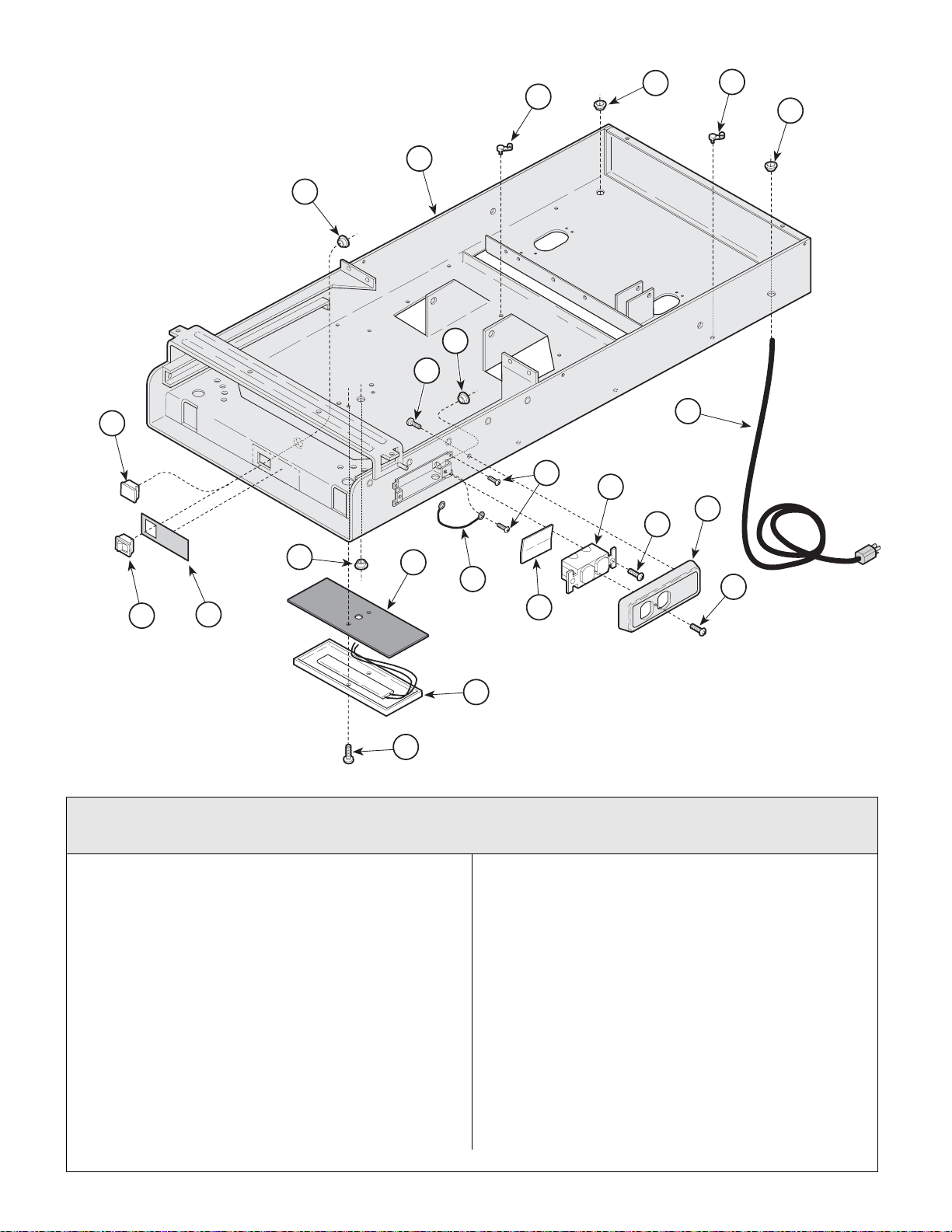
Electrical Components
Return To Table Of Contents
(120 VAC Units)
20
14
5
SECTION VI
PARTS LIST
19
22
4
1
2
11
3
5
7
9
8
12
15
13
16
21
10
6
17
18
MA354401i
Used on units with Serial Number GJ8691, GK13747, E1646, JF1218, JG3106, & JH1418 thru
Present. Used on units with Serial Number V2200 thru Present
Item Part No. Description Page Item Part No. Description Page
1 015-0007-04 Wrap-N-Tap Wire Clamp........................3
2 053-0068-00 Snap Bushing ........................................1
3 015-0066-03 Power Cord Assembly ...........................1
4 053-0068-10 Snap Bushing ........................................1
5 040-0010-47 Screw..................................................... 3
6 053-0092-00 Fishpaper Insulator................................ 1
7 015-0083-01 Duplex Receptacle (Refer to “Wiring
Diagram [Section 5] for Wire Numbers ..1
8 040-0006-13 Screw..................................................... 2
9 053-0836-00 Receptacle Cover .................................. 1
053-1294-00 No Electric Cover (Canadian units only) 1
10 040-0006-23 Screw..................................................... 1
11 053-0350-02 Heater Plug (Units w/o Heater Only) ..... 1
12 015-0650-00 Heater Switch (Units w/ Heater Only) .... 1
13 061-0294-00 Caution Label (Units w/ Heater Only) ....1
14 053-0068-10 Snap Bushing (Units w/ Heater Only) .... 1
© Midmark Corporation 1999 SF-1532 Printed in U.S.A.
Rev. 5/05
15 053-0068-01 Snap Bushing (Units w/ Heater Only) ... 1
16 053-0362-00 Heat Shield (Units w/ Heater Only) ....... 1
17 002-0554-00 Heater Plate Assembly-60 Watt (Includes
Items 16 and 18) (Units w/ Heater Only)
(Refer to “Wiring Diagram” {Section 5}
for Wire Numbers)................................. 1
18 040-0010-35 Screw (Units w/ Heater Only)................ 2
19 015-0007-00 Wrap-N-Tap Wire Clamp (Units w/
Heater Only).......................................... 1
20 Upper Wrap (Refer to “Upper Wrap
Assembly” Elsewhere)........................ Ref
21 Jumper Wire (Refer to “Wiring
Diagram {Section 5} for Wire Numbers) 1
22 053-0068-06 Snap Bushing (304-017 only) ............... 1
23 015-1596-00 Circuit Breaker - 9A (304-018/021 only) 2
Always Specify Model & Serial Number
Page 6-10.1
Page 67
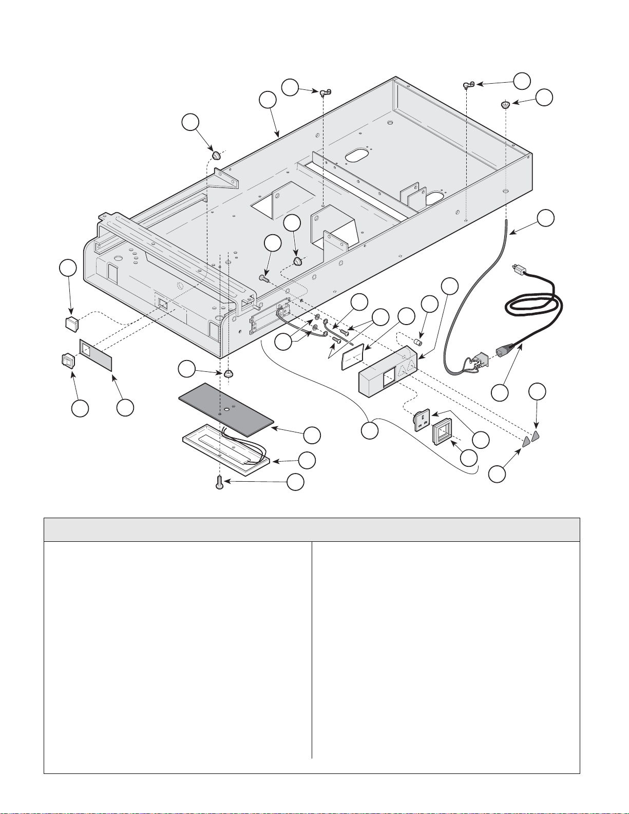
Electrical Components
Return To Table Of Contents
(220 VAC Units)
SECTION VI
PARTS LIS T
16
19
20
25
24
1
2
6
3
5
12
8
9
11
10
7
27
MA482300
17
18
23
21
22
15
4
14
13
26
Used on units with Serial Number GL1000 thru GL1231 & LC1000 thru LC24 52
Item Part No. Description Page Item Part No. Description Page
1 015-0007-04 Wrap-N-Tap Wire Clamp........................3
2 053-0068-00 Snap Bushing ........................................1
3 Appliance Inlet Harness (Refer to
“Wiring Diagram” [Section 5] for
Wire Numbers........................................ 1
4 Receptacle Assembly (Includes Items 5
thru 15) (Refer to “Receptacle
Assembly” Elsewhere)......................... 1
5 • • Screw................................................... 2
6 • • Snap Bushing ...................................... 1
7 • • Lock Washer........................................2
8 • • Jumper Wire ........................................1
9 • • Screw................................................... 2
10 • • Fishpaper ............................................ 1
11 • • Nutsert................................................. 2
12 • • Receptacle Cover................................ 1
13 • • Bezel.................................................... 1
14 • • Export Receptacle (UK shown) ........... 1
Always Specify Model & Serial Number
15 • • Cord Set
(Refer to: Receptacle Assembly)...Ref
16 053-0350-02 Heater Plug (Units w/o Heater Only)..... 1
17 015-0650-00 Heat Switch (Units w/ Heater Only)....... 1
18 061-0676-00 Multinational Heater Switch Label
(Units w/ Heater Only)........................... 1
19 053-0068-00 Snap Bushing (Units w/ Heater Only) ... 1
20 053-0068-01 Snap Bushing (Units w/ Heater Only) ... 1
21 029-1222-01 Heater Plate Assembly - 50 Watt
(Units w/ Heater Only)........................... 1
22 053-0362-00 Heat Shield (Units w/ Heater Only) ....... 1
23 040-0010-35 Screw (Units w/ Heater Only)................ 2
24 015-0007-00 Wrap-N-Tap (Units w/ Heater Only)....... 4
25 Upper Wrap (Refer to “Upper Wrap
Assembly” Elsewhere............................ 1
26 061-0654-00 Caution Label (Units w/ Receptacle) ..... 1
27 061-0650-00 Dangerous Voltage Label
(Units w/ Receptacle)............................ 1
© Midmark Corporation 1999 SF-1532 Printed in U.S.A.
Rev. 7/05
Page 6-11
Page 68
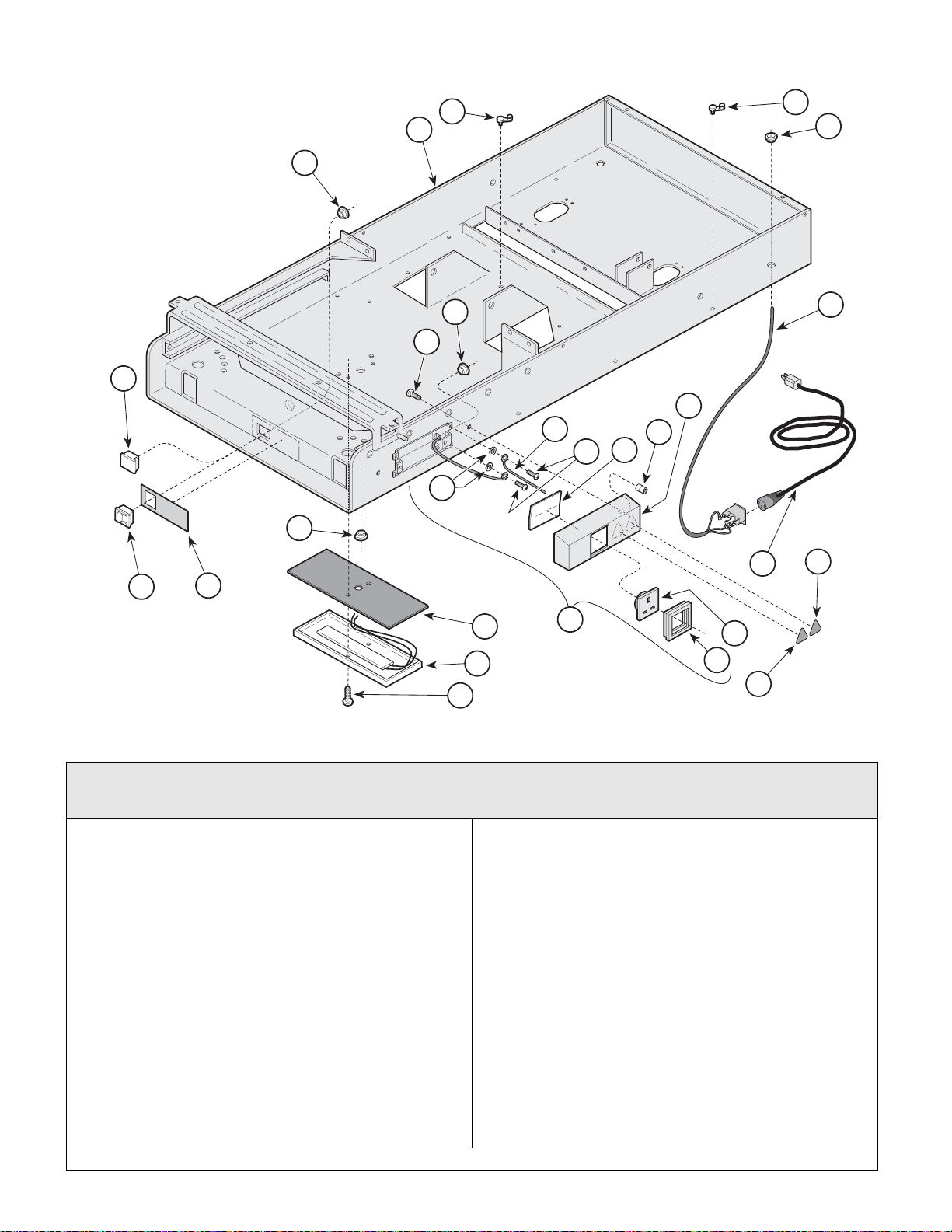
Electrical Components
Return To Table Of Contents
(220 VAC Units)
25
19
24
SECTION VI
PARTS LIS T
1
2
16
17
18
20
6
3
5
12
8
9
11
10
7
27
MA482300
23
21
22
15
4
14
13
26
Used on units with Serial Number GL1232 & LC2453 thru Present
Used on units with Serial Number V2200 thru Present
Item Part No. Description Page Item Part No. Description Page
1 015-0007-04 Wrap-N-Tap Wire Clamp........................3
2 053-0068-10 Snap Bushing ........................................1
3 Appliance Inlet Harness (Refer to
“Wiring Diagram” [Section 5] for
Wire Numbers.................................... 1
4 Receptacle Assembly (Includes Items 5
thru 15) (Refer to “Receptacle
Assembly” Elsewhere)......................... 1
5 • • Screw...................................................2
6 • • Snap Bushing ...................................... 1
7 • • Lock Washer........................................ 2
8 • • Jumper Wire ........................................ 1
9 • • Screw...................................................2
10 • • Fishpaper ............................................ 1
11 • • Nutsert.................................................2
12 • • Receptacle Cover ................................ 1
13 • • Bezel....................................................1
14 • • Export Receptacle (UK shown) ........... 1
© Midmark Corporation 1999 SF-1532 Printed in U.S.A.
Rev. 7/05
15 • • Cord Set
(Refer to: Receptacle Assembly)...Ref
16 053-0350-02 Heater Plug (Units w/o Heater Only)..... 1
17 015-0650-00 Heat Switch (Units w/ Heater Only)....... 1
18 061-0676-00 Multinational Heater Switch Label
(Units w/ Heater Only)........................... 1
19 053-0068-10 Snap Bushing (Units w/ Heater Only) ... 1
20 053-0068-01 Snap Bushing (Units w/ Heater Only) ... 1
21 029-1222-01 Heater Plate Assembly - 50 Watt
(Units w/ Heater Only)........................... 1
22 053-0362-00 Heat Shield (Units w/ Heater Only) ....... 1
23 040-0010-35 Screw (Units w/ Heater Only)................ 2
24 015-0007-00 Wrap-N-Tap (Units w/ Heater Only)....... 4
25 Upper Wrap (Refer to “Upper Wrap
Assembly” Elsewhere............................ 1
26 061-0654-00 Caution Label (Units w/ Receptacle) ..... 1
27 061-0650-00 Dangerous Voltage Label
(Units w/ Receptacle)............................ 1
Always Specify Model & Serial Number
Page 6-11.1
Page 69
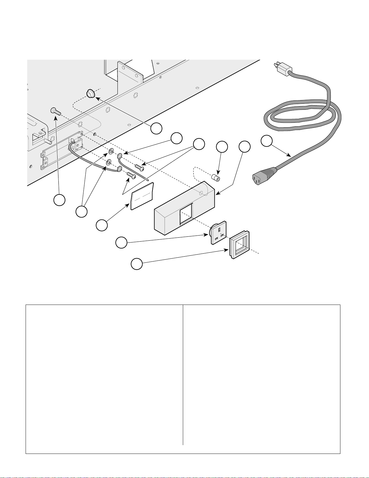
Receptacle Assembly
Return To Table Of Contents
(220 VAC Units)
6
SECTION VI
PARTS LIS T
7
8
9
10
11
1
2
3
4
5
MA482400
Item Part No. Description Page Item Part No. Description Page
9A234001 Receptacle Assembly - Belgium
(Includes Items 1 thru 11)......................1
9A234002 Receptacle Assembly - Europe
(Includes Items 1 thru 11)......................1
9A234003 Receptacle Assembly - United Kingdom
(Includes Items 1 thru 11)......................1
9A234004 Receptacle Assembly - Italy
(Includes Items 1 thru 11)......................1
9A234006 Receptacle Assembly - Australia
(Includes Items 1 thru 11)......................1
9A234007 Receptacle Assembly - No Receptacle
(Includes Items 1, 9, 10 and 12) ........... 1
1 • 040-0010-34 • Screw...................................................2
2 • 045-0001-31 • Lockwasher .........................................2
3 • 053-0092-00 • Fishpaper Insulator.............................. 1
4 • 015-1294-00 • Receptacle - Europe............................1
• 015-1294-01 • Receptacle - Belgium .......................... 1
• 015-1294-02 • Receptacle - United Kingdom (Shown)1
• 015-1294-03 • Receptacle - Italy................................. 2
• 015-1294-05 • Receptacle - Australia .........................1
Always Specify Model & Serial Number
5 • 015-0704-00 • Receptacle Bezel ................................ 1
6 • 015-0068-07 • Snap Bushing...................................... 1
7 • 015-0547-01 • Jumper Wire........................................ 1
8 • 040-0010-47 • Screw .................................................. 2
9 • 042-0045-01 • Nutsert ................................................ 2
10 • 050-4162-40 • Receptacle Cover w/ Cutout
(Units w/ receptacle)........................... 1
• 050-4162-41 • Receptacle Cover w/o Cutout
(Units w/o receptacle)......................... 1
11 • 015-0363-00 • Cordset - Belgium / Europe................. 1
• 015-0363-01 • Cordset - Italy...................................... 1
• 015-0363-03 • Cordset - United Kingdom................... 1
• 015-0363-04 • Cordset - Australia .............................. 1
12 • 050-4152-00 • Appliance Inlet Cover (Not Shown -
Refer to “Cabinet Components [Export]”
Elsewhere) (Units w/o Receptacle)..... 1
© Midmark Corporation 1999 SF-1532 Printed in U.S.A.
Rev. 11/99
Page 6-12
Page 70
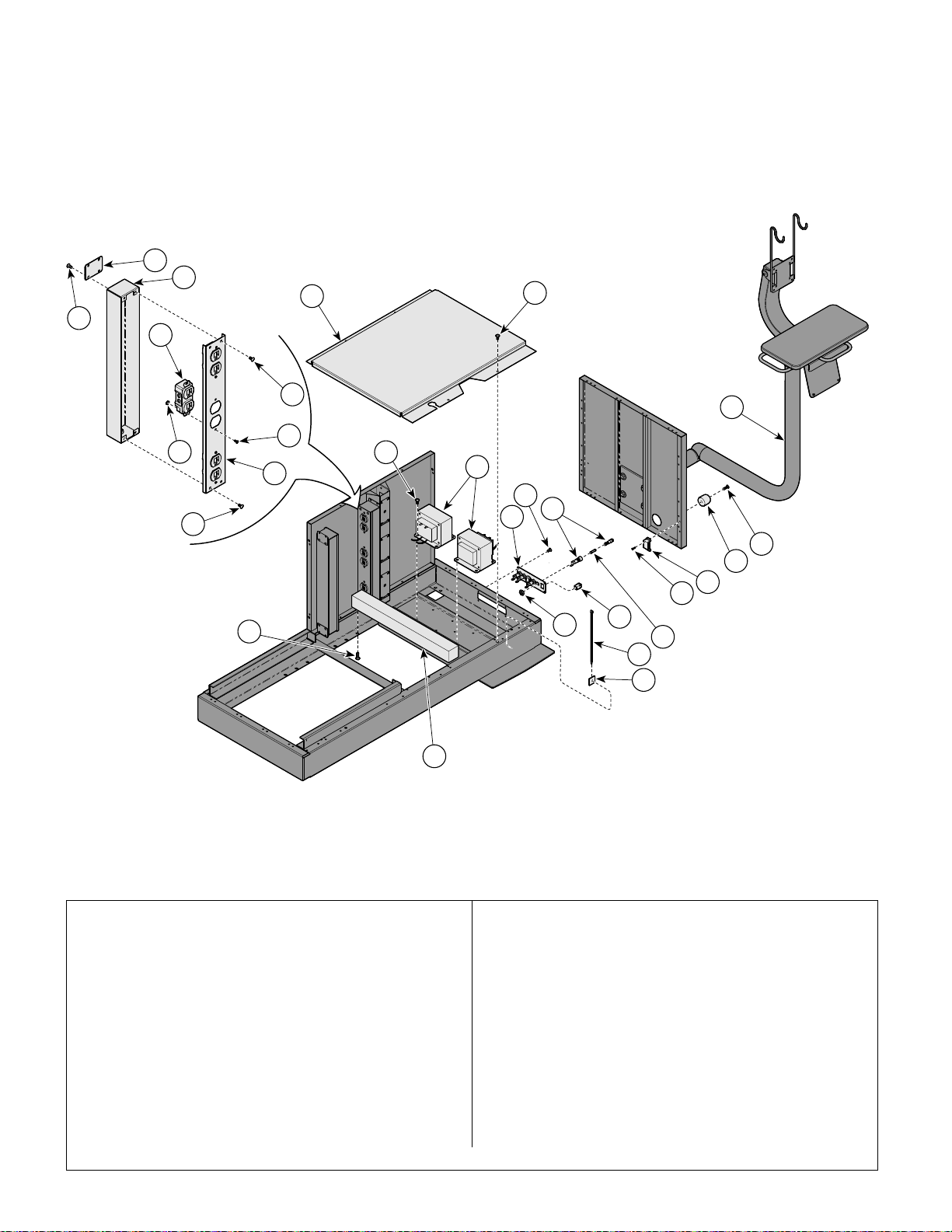
IPET Components
Return To Table Of Contents
18
17
16
19
21
SECTION VI
PARTS LIS T
9
22
19
14
23
19
20
1
9
15
9
7
10
2
3
4
5
7
8
6
11
12
13
Item Part No. Description Page Item Part No. Description Page
1 IPET Monitor Arm Assembly (refer to
“IPET Monitor Arm Assembly”
elsewhere)) ........................................ Ref
2 040-0010-159 Screw .....................................................2
3 053-1290-00 Recess Bumper ..................................... 2
4 016-0999-00 Magnet (Includes Screw ........................1
5 040-0006-80 Screw..................................................... 4
6 015-0346-02 Slow-Blo Fuse (6.3 A / 250V) ................ 4
7 015-1259-01 Fuse Holder Assembly........................... 4
8 015-1840-00 Lans Coupler .........................................1
9 040-0010-00 Screw ..................................................16
10 050-5592-30 Port Plate...............................................1
11 102308 Cable Tie ............................................... 1
© Midmark Corporation 1999 SF-1532 Printed in U.S.A.
MA681200i
12 123058 Cable Tie Mounting Platform................. 1
13 051-1072-30 Counter Balance Weight ....................... 3
14 040-0250-43 Screw .................................................... 6
15 015-1829-00 Isolation Transformer............................. 2
16 050-6163-30 Bottom Access Panel ............................ 1
17 050-6164-40 Receptacle Box ..................................... 1
18 050-6175-40 Receptacle Mounting Plate ................... 2
19 040-0010-00 Screw .................................................. 12
20 040-0006-10 Screw .................................................... 6
21 015-0083-01 Duplex Receptacle ................................ 3
22 041-0006-00 Hex Nut ................................................. 6
23 050-6165-40 Receptacle Cover.................................. 1
Always Specify Model & Serial Number
Page 6-13
Page 71
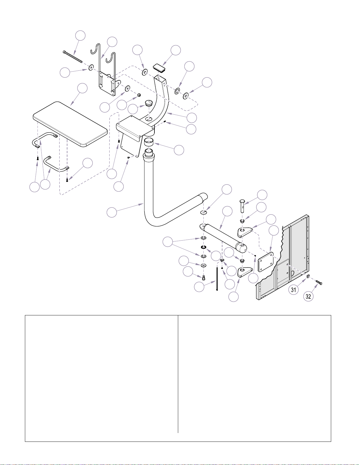
IPET Monitor Arm Assembly
Return To Table Of Contents
1
2
6
7
10
8
7
3
14
15
4
5
9
11
12
SECTION VI
PARTS LIS T
6
14
13
22
27
28
16
24
29
26
30
17
29
18
19
20
21
25
23
22
26
MA681300i
Item Part No. Description Page Item Part No. Description Page
029-3376-00 IPET Monitor Arm Assembly
(Includes Items 1 thru 32)......................1
1 • 040-0250-147 • Screw................................................... 1
2 • 030-1537-40 • Vesa Mount Weldment ........................1
3 • 053-0452-02 • Wire/Cap Grommet ............................. 1
4 • 053-1483-00 • Rectangular Plug................................. 1
5 • C5593 • Spring Washer..................................... 1
6 • 120744-6 • Arm Pivot Washer................................ 2
7 • 045-0001-60 • Washer ................................................ 2
8 • 041-0250-01 • Locknut................................................1
9 • 030-1447-40 • Center Spine Weldment ...................... 1
10 • 068-0189-00 • Keyboard Pedestal ..............................1
11 • 040-0010-153 • Screw...................................................1
12 • 016-0149-21 • Iglide Bearing ...................................... 1
13 • 057-0654-40 • Monitor Shelf Handle ........................... 2
14 • 040-0010-137 • Screw...................................................4
15 • 040-0010-12 • Screw................................................... 4
Always Specify Model & Serial Number
16 • 030-1535-40 • Radius Arm Weldment ........................ 1
17 • 155436 • Washer................................................ 2
18 • 109457 • Thrust Bearing .................................... 1
19 • 050-5985-00 • Bearing Spacer ................................... 1
20 • 117471 • Shoulder Screw................................... 1
21 • 016-0889-00 • Cable Tie Mounting Platform............... 1
22 • 040-0010-109 • Screw .................................................. 3
23 • 102308 • Cable Tie............................................. 1
24 • 030-1536-40 • Arm Mount Weldment ......................... 1
25 • 040-0375-69 • Set Screw............................................ 1
26 • 051-1073-40 • Hitch Plate........................................... 2
27 • 053-1116-00 • Washer................................................ 1
28 • 057-0825-00 • Hitch Pin.............................................. 1
29 • 016-0998-00 • Bronze Flange Sleeve Bearing ........... 2
30 • 051-1074-40 • Mount Plate......................................... 1
31 • 045-0001-01 • Washer................................................ 4
32 • 040-0375-36 • Screw .................................................. 4
© Midmark Corporation 1999 SF-1532 Printed in U.S.A.
Page 6-14
Page 72

Return To Table Of Contents
Page 73

COMMENTS
Return To Table Of Contents
The Technical Publications Department of Midmark
Corporation takes pride in its publications. We are sure
that our manuals will fill all of your needs when you are
performing scheduled maintenance, servicing, or
repairs on a Midmark product.
Page(s) and Paragraph(s) Needing Changed:
Description of Error or Desired Change:
However, if you find any errors or feel that there should
be a change, addition, or deletion to a manual, please
let us know!
Please fax or mail a copy of this completed comment
sheet to:
Midmark Corporation
ATTN: Technical Publications Department
60 Vista Drive
Versailles, Ohio 45380
Fax: (937) 526-5542
© Midmark Corporation 1997 SF-1532 Page 7-1 Printed in U.S.A.
Page 74
FAX ORDERING FORM
Return To Table Of Contents
(SERVICE PARTS ONLY)
NOTES:
• ALL BLOCKED AREAS MUST BE COMPLETED.
• USE FOR NON-WARRANTY FAX ORDERS ONLY. WARRANTY ORDERS MUST BE TELEPHONED IN (1-800-MIDMARK).
ATTENTION: SERVICE DEPARTMENT FAX#: 877-249-1793
ACCT #: P.O. #: DATE:
NAME: SHIP TO:
ADDRESS:
CITY, ST.:
CONTACT:
PHONE:
NON-EMERGENCY ORDER - TO SHIP WITHIN 72 HOURS IF
PART(S) IN STOCK.
EMERGENCY ORDER - TO SHIP WITHIN 24 HOURS IF PART(S)
IN STOCK (IF ORDER IS RECEIVED BEFORE 1:00 P.M. E.S.T).
SEND NOTIFICATION IF PARTS ARE NOT AVAILABLE TO SHIP
WITHIN 24 HOURS VIA
E-MAIL OR FAX TO:
METHOD OF SHIPMENT
UPS
NEXT DAY A.M.
NEXT DAY P.M.
2ND DAY
GROUND
FED EX
NEXT DAY A.M.
NEXT DAY P.M.
2ND DAY
ECONOMY
OTHER
QTY. PART # DESCRIPTION (SPECIFY COLOR OF ITEM IF APPLICABLE) COLOR CODE PRICE/PER
© Midmark Corporation 2000 Rev. 1/07 Page 7-2 Printed in U.S.A.
TOTAL COST: $
Page 75

Return To Table Of Contents
Page 76

Midmark Corporation
Return To Table Of Contents
60 Vista Drive
P.O. Box 286
Versailles, Ohio 45380-0286
937-526-3662
Fax 937-526-5542
midmark.com
© Midmark Corporation - 2005 Printed in U.S.A.
Subject to change without notice.
Refer to www.Documark.com for latest revision.
 Loading...