

Midmark 491 Service And Parts Manual
491
-001 thru -002
Service and
Parts Manual
Power Otolaryngology Chair
NO LONGER IN
Serial Number Prefixes:
CT, DG & V
Some service parts may not
PRODUCTION
be available for this product!
FOR USE BY MIDMARK TRAINED TECHNICIANS ONLY
SF-1496 Part No. 004-0005-00 (12/06/16)
491
-001
thru
-002


TABLE OF CONTENTS
Section/Paragraph Page Section/Paragraph Page
IMPORTANT INSTRUCTIONS
General Safety Instructions......................................... ii
Safety Alert Symbols ................................................... ii
Warranty Instructions .................................................. ii
SECTION I GENERAL INFORMATION
1.1 Scope of Manual ......................................... 1-1
1.2 How to Use Manual ..................................... 1-1
1.3 Description of 491 Power Otolaryngology
Chair ......................................................... 1-1
1.4 Specifications ............................................. 1-4
1.5 Parts Replacement Ordering ....................... 1-4
1.6 Special Tools .............................................. 1-7
SECTION II TESTING AND TROUBLESHOOTING
2.1 Operational Test .......................................... 2-1
2.2 Troubleshooting Procedures ........................ 2-3
SECTION III SCHEDULED MAINTENANCE
3.1 Scheduled Maintenance .............................. 3-1
SECTION IV MAINTENANCE/SERVICE
INSTRUCTIONS
4.1 Introduction ................................................. 4-1
4.2 Membrane Switch Panel Removal /
Installation ................................................ 4-1
4.3 Interface Board Removal / Installation .......... 4-3
4.4 PC Control Board Removal / Installation ...... 4-4
4.5 Back Actuator Removal / Installation ........... 4-6
4.6 Back Capacitor Removal / Installation
(Domestic Units Only) ............................... 4-9
4.7 Thrust Bearing Removal / Installation ......... 4-10
4.8 Base Actuator Removal / Installation ......... 4-13
4.9 Column Assembly Removal / Installation ... 4-17
4.10 Base Capacitor Removal / Installation
(Domestic Units Only) ............................. 4-19
4.11 Typical Capacitor Removal / Installation
(Export Units Only) ................................. 4-20
4.12 Typical Actuator Motor / Actuator Brake
Removal / Installation ............................. 4-21
4.13 Base Down Limit Switch Removal /
Installation / Adjustment ......................... 4-22
4.14 Back Up Limit Switch Removal /
Installation / Adjustment ......................... 4-24
4.15 Typical Foot Pedal Footswitch Removal /
Installation .............................................. 4-25
4.16 Arm Rest Linkage Adjustment.................... 4-26
4.17 Chair Rotational Lock Adjustment .............. 4-27
4.18 Headrest Assembly Adjustment ................. 4-28
4.19 Headrest Handles Handle Stops
Adjustment ............................................. 4-29
4.20 Column Eccentric Tires Adjustment ........... 4-29
4.21 Foot Rest Stop Adjustment ........................ 4-31
4.22 Main Harness Replacement ....................... 4-32
SECTION V SCHEMATICS AND DIAGRAMS
5.1 Electrical Schematics / Wiring Diagrams ...... 5-1
5.2 Diagnostic L.E.D. Charts .............................. 5-4
SECTION VI PARTS LIST
6.1 Introduction ................................................. 6-1
6.2 Description of Columns ............................... 6-1
6.3 Torque Specifications And Important
Assembly Notes ....................................... 6-1
Pictorial Index .............................................. 6-2
Upholstery Components ............................ 6-3(*)
Chair Frame Assembly .............................. 6-4(*)
Headrest Assembly ................................... 6-5(*)
Back Mechanism ...................................... 6-6(*)
Linkage Mechanism .................................. 6-7(*)
Back Actuator Assembly .......................... 6-8(*)
Seat Pivot Mechanism .............................. 6-9(*)
Elevation Column Assembly ................... 6-10(*)
Base Assembly ....................................... 6-11(*)
Base Actuator Assembly ........................ 6-12(*)
Receptacle Panel Assembly (Domestic) . 6-13(*)
Receptacle Panel Assembly (Export) ......... 6-14
COMMENTS ............................................................ 7-1
FAX ORDERING FORM .......................................... 7-2
(*) Indicates that there has been a serial number break for the illustration
and that there are additional point page(s) following the original page.
© Midmark Corporation 1996 SF-1496 Rev. 12/03 Page i Printed in U.S.A.
IMPORTANT INSTRUCTIONS
General Safety Instructions
Safety First: The primary concern of Midmark
Corporation is that this chair is maintained with the
safety of the patient and staff in mind. To assure that
services and repairs are completed safely and correctly,
proceed as follows:
(1) Read this entire manual before performing any
services or repairs on this chair.
(2) Be sure you understand the instructions
contained in this manual before attempting to
service or repair this chair.
Safety Alert Symbols
Throughout this manual are safety alert symbols that
call attention to particular procedures. These items are
used as follows:
DANGER
A DANGER is used for an imminently
hazardous operating procedure,
practice, or condition which, if not correctly
followed, will result in loss of life or serious
personal injury.
NOTE
A NOTE is used to amplify an operating procedure,
practice or condition.
Warranty Instructions
Refer to the Midmark “Limited Warranty” printed in the
Installation and Operation Manual for warranty information. Failure to follow the guidelines listed below will
void the warranty and/or render the 491 Otolaryngology
Chair unsafe for operation.
• In the event of a malfunction, do not attempt to
operate the chair until necessary repairs have been
made.
• Do not attempt to disassemble chair, replace malfunctioning or damaged components, or perform
adjustments unless you are one of Midmark’s
authorized service technicians.
• Do not substitute parts of another manufacturer
when replacing inoperative or damaged components.
Use only Midmark replacement parts.
WARNING
A WARNING is used for a potentially
hazardous operating procedure,
practice, or condition which, if not correctly
followed, could result in loss of life or serious
personal injury.
CAUTION
A CAUTION is used for a potentially
hazardous operating procedure, practice,
or condition which, if not correctly followed, could
result in minor or moderate injury. It may also be
used to alert against unsafe practices.
EQUIPMENT ALERT
An EQUIPMENT ALERT is used for an
imminently or potentially hazardous
operating procedure, practice, or condition which, if
not correctly followed, will or could result in serious,
moderate, or minor damage to unit.
© Midmark Corporation 1996 SF-1496 Page ii Printed in U.S.A.

SECTION I
GENERAL INFORMATION
SECTION I
GENERAL INFORMATION
1.1 Scope of Manual
This manual contains detailed troubleshooting, scheduled maintenance, maintenance, and service instructions for 491 Power Otolaryngology Chair. This manual
is intended to be used by Midmark’s authorized service
technicians.
1.2 How to Use Manual
A. Manual Use When Performing Scheduled Mainte-
nance.
(1) Perform inspections and services listed in
Scheduled Maintenance Chart (Refer to
para 3.1).
(2) If a component is discovered to be faulty or out
of adjustment, replace or adjust component in
accordance with maintenance/service instructions (Refer to para 4.1).
B. Manual Use When Chair Is Malfunctioning And
Cause Is Unknown.
medical examinations and procedures on ears, noses,
and throats.
The major serviceable components of the table are the
PC control board, membrane switch panels, interface
board, back actuator, back capacitor, base actuator,
base capacitor, base down limit switch, back up limit
switch, headlock assembly, elevation column assembly
which includes eccentric bearings, chair rotational lock
assembly, back linkage mechanism, pivot thust bearing,
and foot control which includes four footswitches.
B. Theory of Operation (See Figures 5-1 and 5-2
for wiring diagrams / electrical schematics)
Electrical Power:
Line voltage (115 VAC for domestic units and 230 VAC
for export units) is supplied to the chair's PC control
board. There is a transformer and associated follow-on
circuitry on the PC control board which reduces the line
voltage to approximately 12 VDC. The 12 VDC provides power to operate the circuitry of the PC control
board, membrane switch panels, and foot control.
(1) Perform an operational test on chair (Refer to
para 2.1).
(2) Perform troubleshooting procedures listed in
Troubleshooting Guide (Refer to para 2.2).
(3) If a component is discovered to be faulty or out
of adjustment, replace or adjust component in
accordance with maintenance/service instructions (Refer to para 4.1).
C. Manual Use When Damaged Component Is Known.
(1) Replace or adjust component in accordance
with maintenance/service instructions (Refer to
para 4.1).
1.3 Description Of 491 Power Otolaryngology Chair
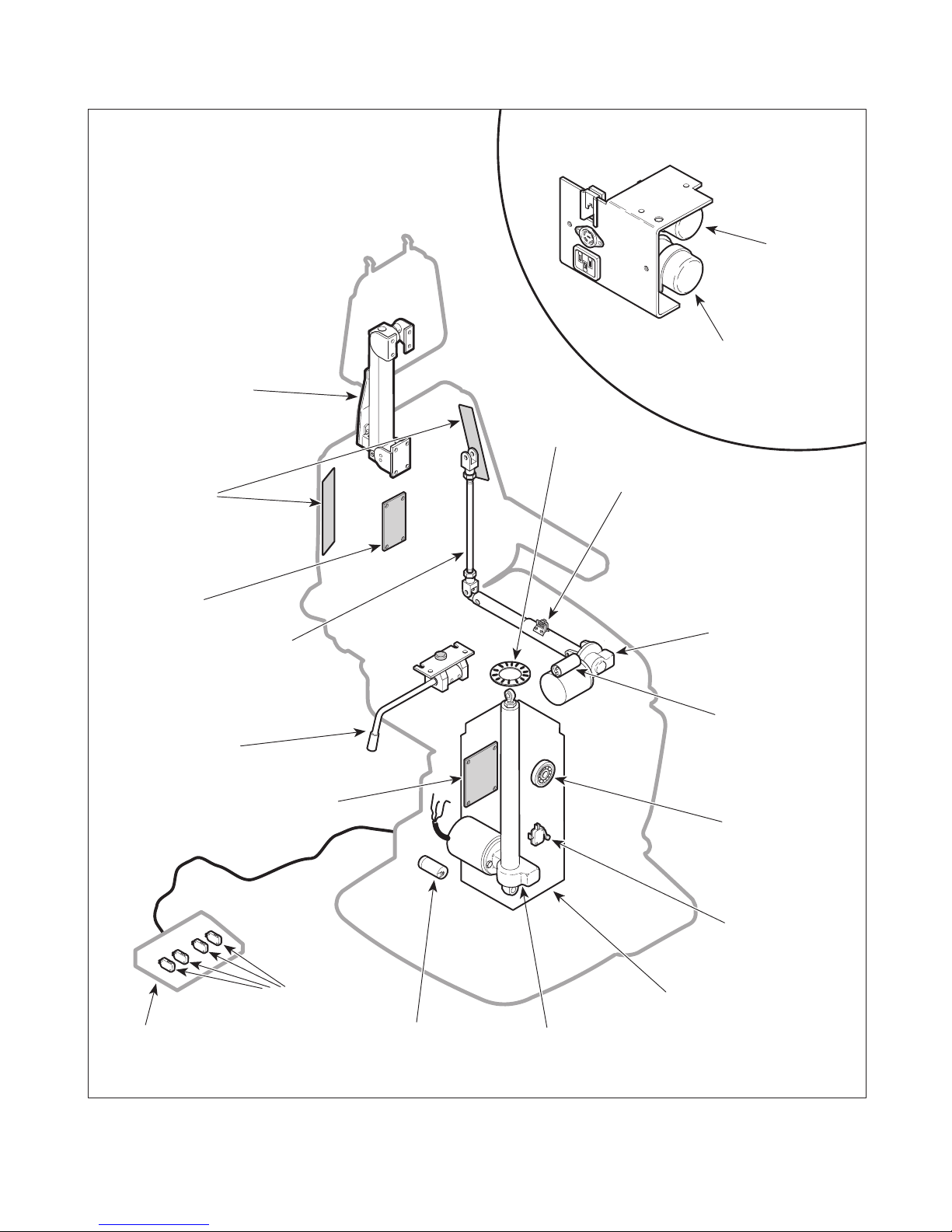
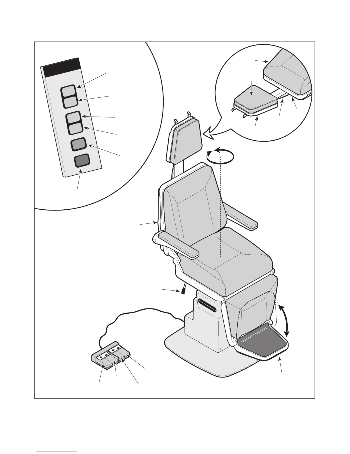
A. General Description (See Figure 1-1).
The 491 Power Otolaryngology Chair is an examination
chair designed specifically for performing general
On domestic units, 115 VAC is continuously supplied to
the electrical receptacle. Export units do not have
electrical receptacles.
Chair Operation using Switch Membranes or Hand
Control:
When a manual function button is pressed, the switch
membranes send signals to the PC control board using
three data lines. The PC control board determines
which function was selected by analyzing which data
lines contained a signal and then the PC control board
energizes the relay for the selected function.
There is always line voltage at the common contact
(output) of the relays and there is a relay for each up
and down function: BASE UP, BASE DOWN, BACK
UP, and BACK DOWN. So, when a relay is energized,
line voltage is applied thru the relay and then across the
motor coil of the selected function, causing it to run.
When the button is released, the function's relay is deenergized, removing line voltage from the motor coil
which causes it to stop running. The BASE DOWN
function has an additional control circuit to prevent it
from being freewheeled at the end of its down travel.
© Midmark Corporation 1996 SF-1496 Page 1-1 Printed in U.S.A.
SECTION I
GENERAL INFORMATION
HEADLOCK
ASSEMBLY
MEMBRANE
SWITCH
PANELS
EXPORT UNIT COMPONENTS
BACK
CAPACITOR
(EXPORT
UNITS ONLY)
BASE
CAPACITOR
(EXPORT
UNITS ONLY)
PIVOT
THRUST
BEARING
BACK UP
LIMIT SWITCH
INTERFACE
BOARD
ROTATIONAL
ASSEMBLY
FOOT
CONTROL
CHAIR
LOCK
BACK
LINKAGE
MECHANISM
PC CONTROL
BOARD
FOOT
SWITCHES
BASE
CAPACITOR
(DOMESTIC
UNITS ONLY)
BASE
ACTUAT OR
BACK
ACTUATOR
BACK
CAPACITOR
(DOMESTIC
UNITS ONLY)
ECCENTRIC
BEARINGS
BASE DOWN
LIMIT SWITCH
ELEVATION
COLUMN
ASSEMBL Y
MA312800
© Midmark Corporation 1996 SF-1496 Page 1-2 Printed in U.S.A.
Figure 1-1. Major Components

SECTION I
GENERAL INFORMATION
When the base down limit switch is tripped, the PC
control board de-energizes the base down relay causing the base actuator to stop running (even if the button
is still being depressed by the operator). This prevents
the base actuator from being freewheeled when it
reaches the end of its down travel. Otherwise, under
heavy loads, excessive wear or damage to base
actuator could result.
When the AUTO RETURN button is depressed, the
switch membranes send signals to the PC control board
using three data lines. The PC control board determines that the AUTO RETURN function was selected
and energizes two relays: the BACK UP relay and the
BASE DOWN relay. The PC control board keeps these
functions running even when the operator releases the
button. Then, the PC control board monitors the status
of the normally open (N.O.) base down limit switch and
N.O. back up limit switch. The N.O. limit switches are
tripped, resulting in a closed circuit, when the actuators
are in all positions but their auto return home position.
When an actuator reaches its auto return home position, the limit switch becomes untripped and the PC
control board de-energizes the relay for that function
causing its actuator to stop. When both limit switches
have become untripped, stopping both actuators, the
auto return function is complete. The PC control board
has a backup timing circuit in case the back up limit
switch or base down limit switch malfunctions during the
auto return function. If the PC control board does not
see the status of both limit switches change within
approximately 17 seconds of actuator run time, the
backup circuit shuts down the auto return function.
The STOP button may be pressed at any time during
the AUTO RETURN function. When the STOP button
is pressed, the switch membranes send a signal to the
PC control board. The PC control board determines
that the STOP function was selected and stops the auto
return function. This de-energizes the base down and
back up relays, stopping the actuators.
Actuator Operation:
The base and back actuators are ball screw driven.
The actuator assemblies contain a pivot point on the
end of the ball screw. If an actuator assembly is run to
the end of its stroke, the ball screw shaft spins inside
the nut, which allows the actuator assembly to run
without damaging or advancing the nut.
The base and back actuators have internal braking
mechanisms which disengage when the motor starts
running and engage when the motor stops running.
Diagnostic L.E.D. Information
There are thirteen L.E.D.'s on the PC logic board which
can be used for troubleshooting aids. Table 5-1 lists all
functions for this chair and which L.E.D's should
illuminate when a button or footswitch is depressed.
See Figure 5-3 for location of L.E.D.'s.
• The back up relay L.E.D. illuminates to indicate that
the PC control board is energizing the back up
relay.
• The back down relay L.E.D. illuminates to indicate
that the PC control board is energizing the back
down relay.
• The base up relay L.E.D. illuminates to indicate that
the PC control board is energizing the base up
relay.
• The base down relay L.E.D. illuminates to indicate
that the PC control board is energizing the base
down relay.
• The foot control back up L.E.D. illuminates to
indicate that the PC control board is receiving a
good signal from the back up foot switch.
• The foot control back down L.E.D. illuminates to
indicate that the PC control board is receiving a
good signal from the back down foot switch.
• The foot control base up L.E.D. illuminates to
indicate that the PC control board is receiving a
good signal from the base up foot switch.
• The foot control base down L.E.D. illuminates to
indicate that the PC control board is receiving a
good signal from the base down foot switch.
• The auto return back function L.E.D. illuminates to
indicate that the auto return circuit for the back
function is activated. The L.E.D. stays illuminated
until the back function has completed its portion of
the auto return cycle.
• The auto return base function L.E.D. illuminates to
indicate that the auto return circuit for the base
function is activated. The L.E.D. stays illuminated
until the base function has completed its portion of
the auto return cycle.
• There are three Data Line L.E.D.'s; data line #1
L.E.D., data line #2 L.E.D., and data line #3 L.E.D..
Different combinations of these L.E.D's illuminate to
indicate if the proper input signal is being sent to
the PC control board from the membrane panels or
hand control.
© Midmark Corporation 1996 SF-1496 Page 1-3 Printed in U.S.A.

SECTION I
GENERAL INFORMATION
General Information:
All actuator motors have a thermal overload switch
which will activate if the actuator assembly is run
continuously. The actuator motor was not designed for
continuous operation. The normal cool off period for
the thermal overload switches is 10 - 20 minutes.
Each actuator motor has a capacitor which provides
start up power and motor run power.
There is a 0.25 amp fuse, located on the PC control
board, which provides over-current protection to the
control circuitry of the PC control board.
There are two 5 amp slow blow fuses, located on the
PC control board, which provide over-current protection
for each function's motor (i.e, Base fuse protects base
actuator motor).
On older units, there is a switch on the PC control
board labeled SW1; this switch must be in the OUT
position or the back up limit switch will be bypassed.
On newer units, there is a jumper connector; this
jumper connector must be removed or the back up limit
switch will be bypassed. This prevents the back
function from moving when the auto return function is
selected.
1.4 Specifications
Table Top Adjustment
Rotation................................................................330°
Back Section ...................................................2 to 90°
Table Top Height (Adjustable):.................... 22.0 in. to
31.0 in.
(55.9 cm to 78.7 cm)
Table Top Speeds (@ 60 Hz.):
Back Down ....................................... 11 +/- 1 seconds
Base Up ............................................ 12 +/-1 seconds
Weight Capacity (Maximum)............. 300 lb. (136.0 kg)
Electrical Requirements:
115 VAC Unit........................... 110 - 120 VAC, 60 HZ,
12 amp, single phase
230 VAC Unit...................... 220 - 240 VAC, 50/60 HZ,
10 amp, single phase
Power Consumption:
115 VAC Unit......................................... 1440 WATTS,
12 amps @ 120 VAC
230 VAC Unit........................................ 2400 WATTS,
10 amps @ 240 VAC
Recommended Circuit:
A separate (dedicated) circuit is recommended for
this chair. The chair
electrical circuit with other appliances or equipment
unless the circuit is rated for the additional load.
should not
be connected to an
Factual data for the 491 Power Otolaryngology Chair is
provided in Table 1-1. Also, see Figure 1-2.
Table 1-1. Specifications
Description Data
Weight:
Without Shipping Carton................ 350 lb (158.8 kg)
With Shipping Carton..................... 375 lb (170.0 kg)
Shipping Carton....... 32 in. "L" x 29 in. "W" x 46 in. "H"
(81.2 cm x 73.66 cm x 116.8 cm)
Dimensions (See Figure 1-2):
Table Top Length (w/ headrest........ 75 in. (190.5 cm)
Table Top Width (w/o arm rests) .... 19.5 in. (49.5 cm)
Overall Width..................................... 26 in. (66.4 cm)
1.5 Parts Replacement Ordering
If a part replacement is required, order the part directly
from the factory as follows:
(1) Refer to Figure 1-3 to determine the location of
the model number and serial number of the
chair and record this data.
(2) Refer to the Parts List to determine the item
numbers of the parts, part numbers of the
parts, descriptions of the parts, and quantities
of parts needed and record this data (Refer to
para 6.1).
NOTE
Ask the Purchasing Department of the company that
owns the chair for this information. Otherwise, this
information may be obtained from the dealer that
sold the chair.
© Midmark Corporation 1996 SF-1496 Rev. 12/97 Page 1-4 Printed in U.S.A.
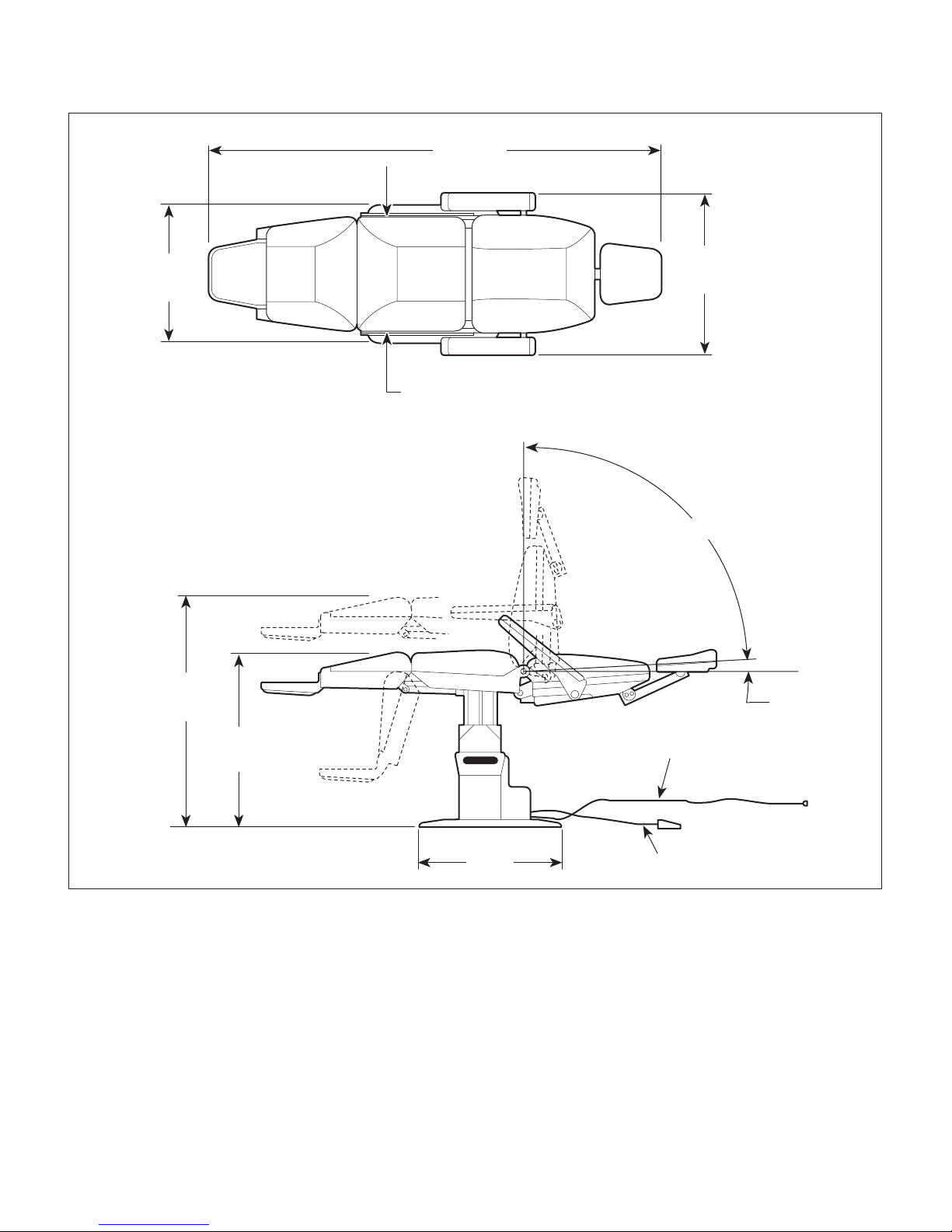
75"
TOTAL
LENGTH
SECTION I
GENERAL INFORMATION
24"
BASE
WIDTH
31"
MAXIMUM
HEIGHT
22"
MINIMUM
HEIGHT
26 1/2"
WIDTH
ACROSS
ARMS
24 1/4"
SEAT
WIDTH
87°
0°
3°
POWER CORD
132"
© Midmark Corporation 1996 SF-1496 Page 1-5 Printed in U.S.A.
24 1/4"
BASE
LENGTH
Figure 1-2. Chair Dimensions
FOOT CONTROL CORD
48"
MA312900

SECTION I
MIDMARK
MODEL NO.
INPUT
RATING
SERIAL NO.
491-00X
115 VAC
12 AMP 60 HZ
XX000000
MODEL
NUMBER
SERIAL
NUMBER
GENERAL INFORMATION
Figure 1-3. Model Number / Serial Number Location
(3) Determine the installation date of the chair and
record this data.
(4) Call Midmark with the recorded information and
ask for the Medical Products Technical Services Department. See back cover of this
manual for the phone number or use the Fax
Order Form (See page 7-2 for Fax Order
Form).
MIDMARK
491
DOWN
BACK
UP
DOWN
TABLE
UP
MA313000
© Midmark Corporation 1996 SF-1496 Page 1-6 Printed in U.S.A.

1.6 Special Tools
Table 1-2 lists all of the special tools needed to repair
the chair, how to obtain the special tools, and the
purpose of each special tool.
Table 1-2. Special Tool List
SECTION I
GENERAL INFORMATION
Description of Special Tool
Multimeter Commercially Available Any Type Used to perform continuity and volt age checks.
Torque Wrench Commercially Available Any Type Used to t i ght en nuts or s cr ews to specified v alues .
Amp Extr act ion Tool Can be purchased from any
Manufacturer's
Name / Address / Phone
authorized Amp distributor.
Manufacturer's
Part Number
458994-2 Used to remove terminal sockets from amp
connectors.
Purpose of Special Tool
© Midmark Corporation 1996 SF-1496 Page 1-7 Printed in U.S.A.

SECTION I
GENERAL INFORMATION
© Midmark Corporation 1996 SF-1496 Page 1-8 Printed in U.S.A.
TESTING AND TROUBLESHOOTING
SECTION II
TESTING AND TROUBLESHOOTING
SECTION II
2.1 Operational Test
In order to effectively diagnose the malfunction of the
chair, it may be necessary to perform an operational
test as follows:
WARNING
Refer to the Operator Manual for
complete instructions on operating the
chair. Failure to do so could result in personal
injury.
NOTE
The Operational Test, for the most part, only describes what should happen when the chair is
operated. If the chair does something other than
described, a problem has been discovered. Refer to
the Troubleshooting Guide to determine the cause of
the problem and its correction.
(1) Plug the chair into a grounded, non-isolated,
correctly polarized outlet, that has the proper
voltage output for the chair.
(4) Repeat steps 2 and 3 on the other membrane
switch panel. If the chair has a foot control,
repeats steps 2 and 3 for these controls also.
(5) Raise BASE UP function all the way up and
BACK DOWN function all the way down.
(6) Press the AUTO RETURN button, wait one
second, and then press the STOP button.
(7) Observe. The BASE DOWN and BACK UP
functions should begin to run. When the STOP
button is pressed, the base and back functions
should stop running.
(8) Press the AUTO RETURN button again.
(9) Observe. The base actuator should lower the
table top all the way down. The base actuator
should not continue to run after table top is
completely lowered. The back actuator should
raise the back section all the way up. The back
actuator should not continue to run after back
section is raised all the way up.
(2) Press BACK UP, BACK DOWN, BASE UP, and
BASE DOWN buttons on one of membrane
switch panels.
(3) Observe. The table top should move in the
direction corresponding to the button which is
being depressed. No section of the table top
should drift on its own after membrane switch
panel button is released. No actuator assembly
should make excessive squealing noises.
Movement should be steady and should match
the speeds and positions listed below:
Chair Speeds (@ 60 Hz.):
Back Down (Up to Down) ................. 11 +/- 1 seconds
Base Up (Down To Up) ..................... 12 +/-1 seconds
Chair Positioning
Back Section ...................................................2 to 90°
Table Top Height (Adjustable): .....................22.0 in. to
31.0 in.
(55.9 cm to 78.7 cm)
(10) Unlock the pivot brake lever and rotate the
table top as far as it will go to the left and then
to the right.
(11) Observe. The table top should be able to be
rotated for approximately 330° of rotation.
Excessive force should not be required to
rotate table top and there should not be squeal-
ing or grinding noises coming from the pivot
point.
(12) Lock the brake lever.
(13) Push on table at various points of the table top.
(14) Observe. The column assembly should not
have excessive play.
(15) Unlock locking handle, position headrest in a
horizontal position as shown, and then relock
locking handle.
(16) Place a 45 lb (20.4 kg) static load at Point A.
© Midmark Corporation 1996 SF-1496 Page 2-1 Printed in U.S.A.
SECTION II
BACK
SECTION
AXIS
"B"
AXIS
"C"
POINT
"A"
LOCKING
HANDLE
TESTING AND TROUBLESHOOTING
MEMBRANE SWITCH PANEL
BACK UP
BUTTON
BACK
UP
BACK
DOWN
BASE
UP
BASE
DOWN
AUTO
RETURN
STOP
STOP
BUTTON
BACK
DOWN
BUTTON
BASE UP
BUTTON
BASE
DOWN
BUTTON
AUTO
RETURN
BUTTON
TABLE
TOP
330°
ROTATION
DOWN
BACK
UP
DOWN
TABLE
UP
TABLE
TABLE
DOWN
UP
© Midmark Corporation 1996 SF-1496 Page 2-2 Printed in U.S.A.
BRAKE
LEVER
FOOT CONTROL
FOOT SWITCHES
BACK
DOWN
BACK
UP
Figure 2-1. Operational Test
MIDMARK
491
FOOT
REST
MA312700

SECTION II
TESTING AND TROUBLESHOOTING
(17) Observe. There should be no movement at
axis B or Axis C when the static load is applied
to the headrest. The maximum force required
to unclamp a locking handle should be 17 lbs.
(7.7 kg) and the maximum force required to
clamp a locking handle should be 35 lbs.
(15.8 kg).
(18) Raise foot rest up to stowed position.
Table 2-1. Troubleshooting Guide
Problem Symptom Probable Cause Check Correction
Chair will not operate
when any of the four up or
down or auto return
functions are selected
from the membrane switch
panels.
When any button is
pressed, nothing happens
(actuator motor(s) does
not run or hum).
Nothing happens when a
membrane button is
pressed, but chair runs
when a foot control foot
switch is depressed.
(19) Observe. The foot rest should not fall down on
its own; it should stay locked in the stowed
position.
2.2 Troubleshooting Procedures
Table 2-1 is a Troubleshooting Guide which is used to
determine the cause of the malfunction.
Power cord is not plugged
into facility wall outlet.
Facility circuit breaker
providing power to chair is
tripped.
Wire connections loose. Check all wiring
0.25 amp transformer
primary fuse on PC control
board is blown.
PC control board is
malfunctioning.
Interface board is
malfunctioning.
PC control board is
malfunctioning.
Check to see if power
cord is plugged in.
Check to see if facility
circuit breaker is tripped.
One way of checking this
is to plug a lamp into wall
outlet that chair was
plugged into.
connections from power
cord to PC control board.
Perform continuity check
on wires. Use
multimeter to check for
proper voltage levels.
Refer to Figure 5-1 or
5-2 for this check.
Perform continuity check
on primary fuse.
Replace suspect PC
control board with known
working PC control
board or use diagnostic
L.E.D. chart (Table 5-1)
to determine location of
malfunction.
Replace suspect
interface board with
known working interface
board.
Replace suspect PC
control board with known
working PC control
board or use diagnostic
L.E.D. chart (Table 5-1)
to determine location of
malfunction.
Plug power cord into facility
wall outlet.
If circuit breaker is tripped,
determine what caused circuit
breaker to trip, correct the
problem, and then reset /
replace circuit breaker.
Clean any dirty connections.
Tighten any loose
connections. Replace any
damaged connections.
Replace blown primary fuse.
Replace PC control board.
Refer to para 4.4. If PC
control board is not receiving
proper inputs per Table 5-1,
replace interface board Refer
to para 4.3.
Replace interface board.
Refer to para 4.3.
Replace PC control board.
Refer to para 4.4. If PC
control board is not receiving
proper inputs per Table 5-1,
replace interface board Refer
to para 4.3.
© Midmark Corporation 1996 SF-1496 Page 2 -3 Printed in U.S.A.

SECTION II
TESTING AND TROUBLESHOOTING
Table 2-1. Troubleshooting Guide - Continued
Problem Symptom Probable Cause Check Correction
One or more functions
cannot be initiated from
a membrane switch
panel.
One or more functions
cannot be initiated from
the optional foot control.
BACK UP and BACK
DOWN functions do not
work. All other
functions work.
Some functions may be
initiated from a membrane
switch panel, but at least one
may not. All functions can
be initiated from the other
membrane switch panel.
Some functions may be
initiated from the foot control,
but at least one may not. All
functions can be initiated
from the membrane switch
panel.
When BACK UP and BACK
DOWN buttons are pressed,
the chair will not move (all
other functions work).
One of the button
membranes on the
membrane switch panel is
malfunctioning.
Interface board is
malfunctioning.
Foot switch for
non-operable function is
malfunctioning.
PC control board is
malfunctioning.
Wire connections loose. Check all wiring
Back capacitor is weak or
blown.
Thermal overload switch in
back actuator is activated.
5 amp BACK fuse for
BACK UP and BACK
DOWN functions is blown
(located on PC control
board).
Back actuator assembly is
malfunctioning.
Wire connections loose. Check all wiring
PC control board is
malfunctioning.
Refer to Table 5-1 for this
check. Press each button
of membrane switch
panel to verify that each
button causes the
appropriate L.E.D.’s on
PC control board to
illuminate.
Replace suspect interface
board with known working
interface board.
Perform a continuity
check on suspect foot
switch.
Refer to Table 5-1 and
Figure 5-3 for this check.
Depress each foot switch
on foot control to verify
that each footswitch
causes the appropriate
L.E.D.’s on PC control
board to illuminate.
connections from foot
control to PC control
board. Perform continuity
check on wires. Use
multimeter to check for
proper voltage levels.
Replace suspect back
capacitor with known
working back capacitor.
- Wait 10 to 20 minutes to allow
Refer to Figure 5-1 or 5-2
for this check. Perform a
continuity check on 5 amp
BACK fuse.
Replace suspect back
actuator assembly with
known working back
actuator assembly.
connections to back
actuator assembly.
Replace suspect PC
control board with known
working PC control board.
If appropriate L.E.D’s
illuminate for each button,
replace PC control board.
Refer to para 4.4. If not,
replace membrane switch
panel. Refer to para 4.2.
Replace interface board.
Refer to para 4.3.
Replace foot switch. Refer to
para 4.15.
If appropriate L.E.D’s
illuminate for each foot switch,
replace PC control board.
Refer to para 4.4. If not,
replace malfunctioning foot
switch. Refer to para 4.15.
Clean any dirty connections.
Tighten any loose
connections. Replace any
damaged connections.
Replace back capacitor.
Refer to para 4.6 or 4.11.
back actuator motor to cool.
Replace blown BACK fuse.
Replace actuator motor or
back actuator assembly.
Refer to para 4.12 or 4.5.
Clean any dirty connections.
Tighten any loose
connections. Replace any
damaged connections.
Replace PC control board.
Refer to para 4.4.
© Midmark Corporation 1996 SF-1496 Page 2-4 Printed in U.S.A.

Problem Symptom Probable Cause Check Correction
BASE UP and BASE
DOWN functions do not
work. All other functions
work.
BACK UP function works,
but BACK DOWN
function does not or
BACK DOWN function
works, but BACK UP
function does not. All
other functions work.
Table 2-1. Troubleshooting Guide - Continued
When BASE UP and BASE
DOWN buttons are
pressed, the chair will not
move (all other functions
work).
One function operates
properly, but the other does
not.
TESTING AND TROUBLESHOOTING
Base capacitor is weak or
blown.
Thermal overload switch in
base actuator is activated.
5 amp BASE fuse for
BASE UP and BASE
DOWN functions is blown
(located on PC control
board).
Base actuator assembly is
malfunctioning.
Wire connections loose. Check all wiring
PC control board is
malfunctioning.
Wire connections loose. Check all wiring
Back actuator assembly is
malfunctioning.
PC control board is
malfunctioning (relay for up
or down function is
malfunctioning).
Replace suspect base
capacitor with known
working base capacitor.
- Wait 10 to 20 minutes to allow
Refer to Figure 5-1 or 5-2
for this check. Perform a
continuity check on 5 amp
BASE fuse.
Replace suspect base
actuator assembly with
known working base
actuator assembly.
connections to base
actuator assembly.
Replace suspect PC
control board with known
working PC control board.
connections to back
actuator assembly.
Replace suspect back
actuator assembly with
known working back
actuator assembly.
Refer to Figure 5-3 for
this check. Press BACK
UP and then BACK
DOWN button while
observing the PC control
board. The BACK UP
RELAY L.E.D. should
illuminate when the BACK
UP button is pressed and
the BACK DOWN RELAY
L.E.D. should illuminate
when the BACK DOWN
button is pressed. If not,
PC control board is
malfunctioning.
SECTION II
Replace base capacitor.
Refer to para 4.10 or 4.11.
tilt actuator motor to cool.
Replace blown BASE fuse.
Replace actuator motor or
base actuator assembly.
Refer to para 4.12 or 4.8.
Clean any dirty connections.
Tighten any loose
connections. Replace any
damaged connections.
Replace PC control board.
Refer to para 4.4.
Clean any dirty connections.
Tighten any loose
connections. Replace any
damaged connections.
Replace actuator motor or
back actuator assembly.
Refer to para 4.12 or 4.5
Replace PC control board.
Refer to para 4.4.
© Midmark Corporation 1996 SF-1496 Page 2 -5 Printed in U.S.A.

SECTION II
TESTING AND TROUBLESHOOTING
Table 2-1. Troubleshooting Guide - Continued
Problem Symptom Probable Cause Check Correction
BASE UP function works,
but BASE DOWN function
does not or BASE DOWN
function works, but BASE
UP function does not. All
other functions work.
AUTO RETURN function
does not work.
One function operates
properly, but the other
does not.
When AUTO RETURN
button is pressed,
nothing happens.
When AUTO RETURN
button is pressed,
BACK UP function does
not run, but BASE
DOWN function does.
Wire connections loose. Check all wiring connections to
Base actuator assembly
is malfunctioning.
PC control board is
malfunctioning (relay for
up or down function is
malfunctioning).
AUTO RETURN button
on membrane switch
panel is malfunctioning.
Interface board is
malfunctioning.
The STOP button on
membrane switch panel
is malfunctioning (stuck
closed).
Back up limit switch is
malfunctioning (stuck
open).
Older units - back bypass
switch (SW1), located on
PC control board, is
pushed in. Newer units jumper connector is on
both SW1 pins on PC
control board.
PC control board is
malfunctioning.
base actuator assembly.
Replace suspect base actuator
assembly with known working
base actuator assembly.
Refer to Figure 5-3 for this
check. Press BASE UP and
then BASE DOWN button while
observing the PC control board.
The BASE UP RELAY L.E.D.
should illuminate when the
BASE UP button is pressed
and the BASE DOWN RELAY
L.E.D. should illuminate when
the BASE DOWN button is
pressed. If not, PC control
board is malfunctioning.
Refer to Table 5-1 and Figure
5-3 for this check. Press AUTO
RETURN button of membrane
switch panel and verify that the
button causes the appropriate
L.E.D.’s on PC control board to
illuminate.
Replace suspect interface
board with known working
interface board.
Refer to Figure 5-3 for this
check. If data line #1, #2, and
#3 L.E.D.’s are all illuminated
even though STOP button is
not being pressed, membrane
switch panel is malfunctioning.
Perform continuity check on
back up limit switch. Limit
switch tripped = continuity
between COM. and N.O.
terminals.
Refer to Figure 5-3 for this
check. On older units, check to
see if bypass switch (SW1) is
pushed in. On newer units,
check to see if jumper
connector is on both SW1 pins.
Refer to Figure 5-3 for this
check. After AUTO RETURN
button is pressed, the auto
return back function L.E.D.
should illuminate and stay
illuminated until the back
section is all the way up.
Clean any dirty connections.
Tighten any loose
connections. Replace any
damaged connections.
Replace actuator motor or
base actuator assembly.
Refer to para 4.12 or 4.8.
Replace PC control board.
Refer to para 4.4.
If appropriate L.E.D’s
illuminate for each button,
replace PC control board.
Refer to para 4.4. If not,
replace membrane switch
panel. Refer to para 4.2.
Replace interface board.
Refer to para 4.3.
Replace membrane switch
panel. Refer to para 4.2.
Replace back up limit
switch. Refer to para 4.14.
On older units, pull bypass
switch (SW1) to out
position. On newer units,
remove the jumper
connector from SW1 pins
and discard.
If not, replace PC control
board. Refer to para 4.4. If
L.E.D. does illuminate,
replace interface board.
Refer to para 4.3.
© Midmark Corporation 1996 SF-1496 Rev. 12/97 Page 2 -6 Printed in U.S.A.

TESTING AND TROUBLESHOOTING
Table 2-1. Troubleshooting Guide - Continued
melborPmotpmySesuaCelbaborPkcehCnoitcerroC
SECTION II
noitcnufNRUTEROTUA
.deunitnoC-krowtonseod
.sdnoces
NRUTEROTUAnehW
ESAB,desserpsinottub
tonseodnoitcnufNWOD
PUKCABtub,nur
.seodnoitcnuf
NRUTEROTUAnehW
KCAB,desserpsinottub
stitaspotsnoitcnufPU
ESABtub,levartfodne
noitcnufNWOD
narofnurotseunitnoc
51ot7lanoitidda
.)nepo
.gninoitcnuflam
.)nepo
.gninoitcnuflam
sihctiwstimilnwodesaB
kcuts(gninoitcnuflam
sidraoblortnocCP
.nwod
sihctiwstimilnwodesaB
kcuts(gninoitcnuflam
.slanimret
fotuosrellornmulocesaB
nignitlusertnemtsujda
.hctiwstimilnepo
sidraoblortnocCP
.srellor
.draoblortnoc
esabnokcehcytiunitnocmrofreP
hctiwstimiL.hctiwstimilnwod
neewtebytiunitnoc=deppirt
.slanimret.O.Ndna.MOC
sihtrof3-5erugiFotrefeR
NRUTEROTUAretfA.kcehc
nruterotuaeht,desserpsinottub
dluohs.D.E.Lnoitcnufesab
detanimulliyatsdnaetanimulli
yawehtllasipotelbatehtlitnu
esabnokcehcytiunitnocmrofreP
hctiwstimiL.hctiwstimilnwod
ytiunitnocon=deppirtnu
.O.Ndna.MOCneewteb
nmulocesabfotnemtsujdA
.02.4arap
lortnocCPtcepsusecalpeR
CPgnikrownwonkhtiwdraob
timilnwodesabecalpeR
.31.4arapotrefeR.hctiws
lortnocCPecalper,tonfI
fI.4.4arapotrefeR.draob
,etanimulliseod.D.E.L
.draobecafretniecalper
.3.4arapotrefeR
timilnwodesabecalpeR
.31.4arapotrefeR.hctiws
cirtneccEnmuloCmrofreP
otrefeR.tnemtsujdAeriT
.draoblortnocCPecalpeR
.4.4arapotrefeR
NRUTEROTUAnehW
ESAB,desserpsinottub
taspotsnoitcnufNWOD
tub,levartfodnesti
noitcnufPUKCAB
narofnurotseunitnoc
51ot7lanoitidda
.sdnoces
.flestiybstfird
noitcnufkcabdnaesabehT
setareponoitcnuF
.esiwrehtoylreporp
.)desolc
sihctiwstimilpukcaB
kcuts(gninoitcnuflam
.slanimret
sidraoblortnocCP
.gninoitcnuflam
siekarbrotautcarotoM
.gninoitcnuflam
.draoblortnoc
wenhtiwstnenopmoc
.stnenopmoc
kcabnokcehcytiunitnocmrofreP
hctiwstimiL.hctiwstimilpu
ytiunitnocon=deppirtnu
.O.Ndna.MOCneewteb
lortnocCPtcepsusecalpeR
CPgnikrownwonkhtiwdraob
ekarbrotautcatcepsusecalpeR
.21.4
.41.4arapotrefeR
.4.4arapotrefeR
.hctiwstimilpukcabecalpeR
.draoblortnocCPecalpeR
ekarbrotautcaecalpeR
arapotrefeR.stnenopmoc
© Midmark Corporation 1996 SF-1496 Rev. (9/00) Page 2-7 Printed in U.S.A.

SECTION II
TESTING AND TROUBLESHOOTING
Table 2-1. Troubleshooting Guide - Continued
Problem Symptom Probable Cause Check Correction
Chair moves fine for light
patient, but will not move
or moves slowly for very
heavy patient.
Whirling or squeaking
noise is heard when an
actuator assembly is being
run.
Excessive sideways play
of table top.
Headrest is not operating
properly.
Table top rotation is not
working.
Foot rest will not lock into
stowed position.
Heavy patients cause
chair to malfunction.
Noisy actuator. Foreign matter on ball
Table top is not stable
and can be moved from
side to side.
Headrest drifts
downward while
supporting patients
head.
Headrest locking
handles pop out of
locked position.
When table top is
rotated, squealing noise
is made and / or
excessive force is
required to rotate the
table top.
The table top is rotating
even though the pivot
brake lever is in locked
position.
When foot rest is raised
into stowed position, it
falls down by itself.
Low voltage is being
supplied to chair.
Chair overloaded with too
heavy of a patient.
Capacitor for suspect
function is weak.
screw threads and / or
lack of lubricant.
Eccentric tires are out of
adjustment.
Headrest is out of
adjustment.
Headrest handles handle
stops need adjusted.
Thrust bearing is worn or
damaged.
Chair rotational lock
mechanism is out of
adjustment.
Ball plungers are out of
adjustment.
Check voltage at wall
receptacle - should be 115 +/- 5
VAC for domestic units and 230
+/- 10 VAC for export units.
Maximum weight capacity of
chair is 300 lbs (136.0 kg).
Replace suspect capacitor with
known working capacitor.
Check for foreign matter on ball
screw threads. Check for lack
of lubricant on ball screw
threads.
While observing the eccentric
tires, run BASE UP function all
the way up and then the BASE
DOWN function all the way
down. Any eccentric tires
which do not come into contact
with the inner column and
rotate at least once during the
full extension and retraction of
the column assembly, need
adjusted.
Check adjustment of headrest. Adjust headrest. Refer to
Check adjustment of headrest
handles handle stops.
Replace suspect thrust bearing
with known working thrust
bearing.
Check adjustment of the chair
rotational lock mechanism.
Check the adjustment of the
ball plungers.
Correct low voltage situation
at wall receptacle.
Inform chair operator of
weight limitation.
Replace capacitor.
Clean all foreign matter off
of ball screw threads. Coat
ball screw threads with STP
treatment oil or equivalent.
If actuator assembly is still
noisy, replace it.
Adjust eccentric tires. Refer
to para 4.20.
para 4.18.
Adjust headrest handles
handle stops. Refer to para
4.19.
Replace thrust bearing.
Refer to para 4.7.
Adjust the chair rotational
lock mechanism. Refer to
para 4.17.
Adjust the ball plungers.
Refer to para 4.21.
© Midmark Corporation 1996 SF-1496 Page 2-8 Printed in U.S.A.

SCHEDULED MAINTENANCE
SECTION III
SCHEDULED MAINTENANCE
SECTION III
3.1 Scheduled Maintenance
periodically on the chair. These inspections and
services should be performed as often as indicated in
Table 3-1 is a Scheduled Maintenance Chart which lists
the chart.
the inspections and services that should be performed
Table 3-1. Scheduled Maintenance Chart
Interval Inspection or Service What to Do
Semi-annually Obvious damage Visually check condition of chair for obvious damage such as: cracks in components, missing
Fasteners / hardware Check chair for missing or loose fasteners / hardware. Replace any missing hardware and
Warning and
instructional decals
Pivot points / moving
parts / accessories
Membrane switch panel Check that all membrane switch buttons work when pressed. If not, replace membrane switch
Foot control (optional) Check that foot control works correctly. Make sure all footswitches operate properly. Replace
Auto return function Check that auto return function works correctly. Ensure each actuator stops running when it
Ball screws of actuator
assemblies
Drifting of actuator
assemblies
Arm rests The arm rest should be parallel to the seat section when the back section is all the way up. If not,
Chair rotational lock Move pivot brake lever to the "locked' position and then attempt to rotate the table top. If the
Table top rotation Check that table top can be rotated 330 degrees. Rotation should be easy and noiseless. If not,
Excessive play in
column assembly
Headrest Check that headrest is adjusted properly and will not drift downward on its own under 45 lbs (20.4
Electrical receptacle
(Domestic units only)
Upholstery Check all upholstery for rips, tears, or excessive wear. Replace cushions as necessary.
Accessories Check that all accessories have all of their components and that they function properly. If
Operational Test Perform an Operational Test to determine if the chair is operating within its specifications (Refer
components, dents in components, or any other visible damage which would cause chair to be
unsafe to operate or would compromise its performance. Repair chair as necessary.
tighten any loose hardware as necessary.
Check for missing or illegible decals. Replace decals as necessary.
Lubricate all exposed pivot points, moving parts, and accessories with silicone based lubricant.
panel. Refer to para 4.2.
any malfunctioning footswitches. Refer to para 4.15.
reaches its end of travel and does not "freewheel". If necessary, adjust or replace limit switches.
Refer to para 4.13 or 4.14.
Extend each actuator assembly and wipe ball screw threads down with a rag to remove foreign
matter. Coat as much of the ball screw threads as possible with STP treatment oil or equivalent.
Run each actuator assembly to both ends of its travel a couple of times to spread the oil evenly
over all of the ball screw threads and then remove excess oil. If oil does not correct a squealing
actuator assembly, replace actuator assembly.
Check each actuator assembly for drift. Replace actuator assembly brake components as
necessary. Refer to para 4.12.
adjust the arm rest height. Refer to para 4.16.
table top rotates, adjust the rotational lock mechanism. Refer to para 4.17.
lubricate thrust bearing with vaseline or replace thrust bearing. Refer to para 4.7.
Check that column assembly is stable and does not have excessive side to side play. Observe
the eccentric tires while running the BASE function all the way up and all the way down. Any
eccentric tires which do not come into contact with the inner column and rotate at least once
during the full extension and retraction of the column assembly, need adjusted. If necessary,
adjust and / or replace eccentric tires. Refer to para 4.20.
kg) of static weight. If necessary, adjust headrest. Refer to para 4.18.
Check that the electrical receptacle is functioning properly. Replace receptacle as necessary.
necessary, repair or replace the accessory.
to para 2.1). Replace or adjust any malfunctioning components.
© Midmark Corporation 1996 SF-1496 Page 3-1 Printed in U.S.A.

SECTION III
SCHEDULED MAINTENANCE
© Midmark Corporation 1996 SF-1496 Page 3-2 Printed in U.S.A.
MAINTENANCE / SERVICE
SECTION IV
MAINTENANCE / SERVICE INSTRUCTIONS
SECTION IV
4.1 Introduction
DANGER
Refer to the Operator Manual for
complete instructions on operating the
chair. Failure to do so could result in personal
injury.
NOTE
Perform an operational test on the chair after the
repair is completed to confirm the repair was properly
made and that
The following paragraphs contain removal, installation, repair, and adjustment procedures for the chair.
all
malfunctions were repaired.
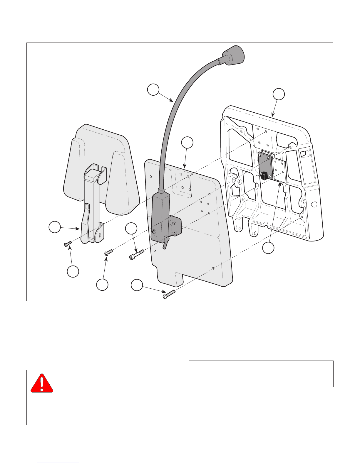
4.2 Membrane Switch Panel Removal /
Installation
A. Removal
NOTE
This art shows removal of the membrane switch
panel from the patients right side of chair. Removal
of membrane switch panel from patients left side of
chair is the same.
(1) Raise BACK UP function all the way up.
(2) Remove four screws (1, Figure 4-1) and
headrest assembly or headrest block (2) from
back casting (3).
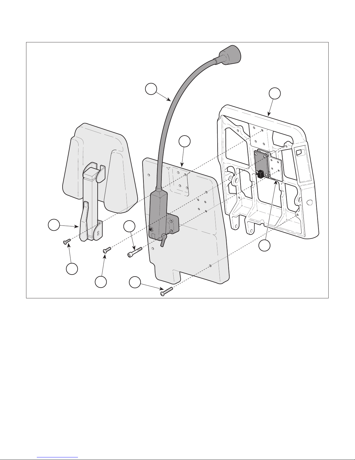
B. Installation
(1) Using warm soapy water, clean back casting
(3, Figure 4-2) in area where membrane switch
panel (1) is to be installed. Allow to dry.
(2) Feed ribbon cable of membrane switch panel
(1) thru cable slot.
(3) Pull paper backing off of membrane switch
panel (1); then press membrane switch panel
firmly into place on back casting (3).
EQUIPMENT ALERT
Use care not to bend, kink, or crease the
ribbon cable of the membrane switch
panel. Failure to use care could result in damage to
ribbon cable.
(4) Connect ribbon cable of membrane switch
panel (1) to interface board (2).
EQUIPMENT ALERT
Overtightening screws (7 and 8) could
cause back cover to crack.
NOTE
The shorter screws go on top.
(5) Install back cover (9, Figure 4-1) on back
casting (3) and secure with two long screws (8)
and two short screws (7). Tighten screws until
back cover starts to deform.
(3) If chair has an optional exam light assembly,
remove four screws (4) and exam light assembly (5) from light bracket (6).
(4) Remove two short screws (7), two long screws
(8), and back cover (9) from back casting (3).
(5) Disconnect ribbon cable of membrane switch
panel (1, Figure 4-2) from interface board (2).
(6) Using screwdriver, gently pry membrane switch
panel (1) off of back casting (3). Remove
membrane switch panel (1) from back casting.
© Midmark Corporation 1996 SF-1496 Page 4-1 Printed in U.S.A.
(6) If removed, install exam light assembly (5) on
light bracket (6) and secure with four
screws (4).
(7) If removed, install headrest assembly or
headrest block (2) on back casting (3) and
secure with four screws (1).
SECTION IV
MAINTENANCE / SERVICE
5
3
9
2
4
6
1
7
Figure 4-1. Back Cover Removal / Installation
8
MA313100
© Midmark Corporation 1996 SF-1496 Page 4-2 Printed in U.S.A.

SECTION IV
MAINTENANCE / SERVICE
RIBBON
3
CABLE
SLOT
CABLE
1
2
PAPER
BACKING
MA313200
Figure 4-2. Membrane Switch Panel
Removal / Installation
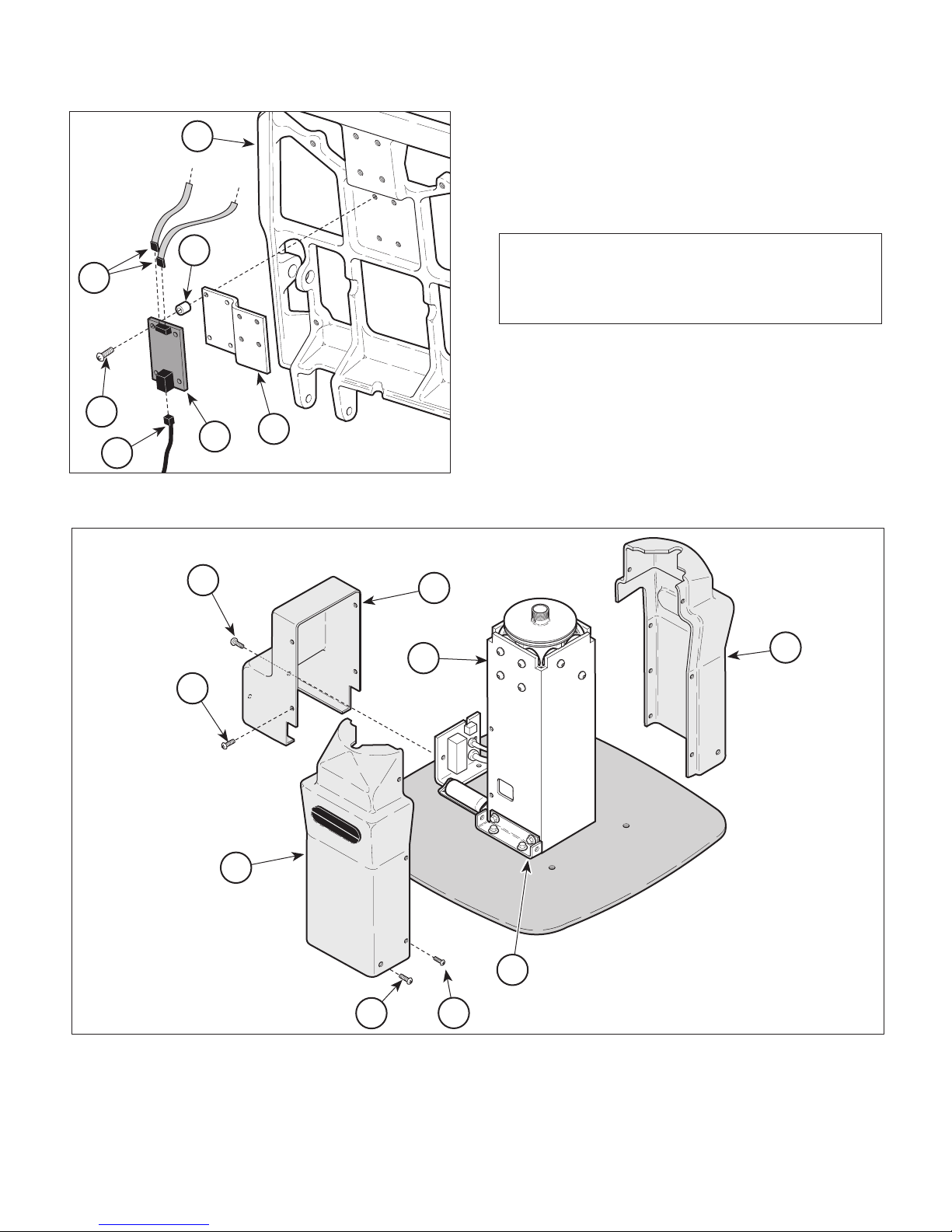
4.3 Interface Board Removal / Installation
(7) Remove four screws (4), spacers (5), interface
board (2), and light bracket (6) from back
casting (7).
B. Installation
(1) Install light bracket (6), four spacers (5, Figure
4-4) and interface board (2) on back casting (7)
and secure with four screws (4).
(2) Connect modular cord (3) to interface
board (2).
EQUIPMENT ALERT
Use care not to bend, kink, or crease the
ribbon cable of the membrane switch
panel. Failure to use care could result in damage to
ribbon cable.
(3) Connect two ribbon cables (1) to interface
board (2).
EQUIPMENT ALERT
Overtightening screws (7 and 8) could
cause back cover to crack.
A. Removal
(1) Raise BACK UP function all the way up.
(2) Remove four screws (1, Figure 4-3) and
headrest assembly or headrest block (2) from
back casting (3).
(3) If chair has an optional exam light assembly,
remove four screws (4) and exam light assembly (5) from light bracket (6).
(4) Remove two short screws (7), two long screws
(8), and back cover (9) from back casting (3).
(5) Disconnect two ribbon cables (1, Figure 4-4)
from interface board (2).
(6) Disconnect modular cord (3) from interface
board (2).
NOTE
Not all units have a light bracket (6).
NOTE
The shorter screws go on top.
(4) Install back cover (9, Figure 4-3) on back
casting (3) and secure with two long screws (8)
and two short screws (7). Tighten screws until
back cover starts to deform.
(5) If removed, install exam light assembly (5) on
light bracket (6) and secure with four
screws (4).
(6) If removed, install headrest assembly or
headrest block (2) on back casting (3) and
secure with four screws (1).
© Midmark Corporation 1996 SF-1496 Page 4-3 Printed in U.S.A.
SECTION IV
MAINTENANCE / SERVICE
5
3
9
2
4
6
1
7
Figure 4-3. Back Cover Removal / Installation
8
4.4 PC Control Board Removal / Installation
A. Removal
(1) If possible, raise BASE UP function all the way up.
WARNING
Always disconnect the power cord
from the wall outlet before removing
any of the chair's covers/shrouds or making any
repairs to prevent the possibility of electrical
shock. Failure to comply with these instructions
could result in severe personal injury or death.
MA313100
(2) Unplug chair power cord from wall outlet.
(3) Remove four screws (1, Figure 4-5), four
screws (2), and R.H. and L.H. shrouds (3) from
base mounts (4).
NOTE
Older units have a slightly different motor cover than
is shown. Removal is similar.
(4) Remove two screws (5), four screws (6), and
motor cover (7) from elevation column (8).
(5) Disconnect three wire harnesses (1, Figure 4-
6) from PC control board (2).
© Midmark Corporation 1996 SF-1496 Rev. 12/97 Page 4-4 Printed in U.S.A.
SECTION IV
MAINTENANCE / SERVICE
(6) Tag and disconnect two modular cords (3) from
7
PC control board (2).
(7) Loosen five terminal screws (4); then tag and
disconnect five wires (5) from PC control
board (2).
5
1
4
2
3
Figure 4-4. Interface Board Removal / Installation
6
MA313300
5
8
6
NOTE
There are two jumper strips which may fall off of
terminal strip during disconnection of wires. Do not
lose.
(8) Remove four screws (6), spacers (7), and PC
control board (2) from elevation column (8).
B. Installation
(1) Install PC control board (2, Figure 4-6) on
elevation column (8) and secure with four
spacers (7) and screws (6).
7
3
MIDMARK
3
Figure 4-5. Shrouds and Motor Cover Removal / Installation
© Midmark Corporation 1996 SF-1496 Rev. 12/97 Page 4-5 Printed in U.S.A.
491
4
1
2
MA313400

SECTION IV
JUMPER
STRIP
3
4
5
1
2
6
7
9
9B
9A
8
MAINTENANCE / SERVICE
(5) Connect three wire harnesses (1) to PC control
board (2).
EQUIPMENT ALERT
On older units, SW1 usually gets pushed
in when top wire harness is connected.
SW1 must be in pulled out position for table to
function properly.
(6) On older units, check position of SW1 (9). If
SW1 is not in pulled out position, pull SW1 out.
On newer units, check to make sure jumper
connector (9A) is not installed. If installed,
remove jumper connector from SW1 pins (9B).
(7) Install motor cover (7, Figure 4-5) on elevation
column (8) and secure with four screws (6) and
two screws (5).
(8) Install R.H. and L.H. shrouds (3) on base
mounts (4) and secure with four screws (2) and
four screws (1).
Figure 4-6. PC Control Board Removal / Installation
(2) Make sure two jumper strips are installed on
terminal strip and did not fall out during wire
disconnection.
(3) Connect five wires (5) to PC control board (2)
and secure by tightening five terminal
screws (4).
(4) Connect two modular cords (3) to PC control
board (2).
(9) Plug chair power cord into wall outlet.
4.5 Back Actuator Removal / Installation
A. Removal
WARNING
Always disconnect the power cord
from the wall outlet before removing
any of the chair's covers/shrouds or making any
repairs to prevent the possibility of electrical
shock. Failure to comply with these instructions
could result in severe personal injury or death.
(1) Unplug chair power cord from wall outlet.
MA313501
© Midmark Corporation 1996 SF-1496 Rev. 12/97 Page 4-6 Printed in U.S.A.
SECTION IV
2
EARLY
UNITS
9
8
10
11
7
LA TER
UNITS
16
15
14
19
20
17
21
2
12
13
18
MAINTENANCE / SERVICE
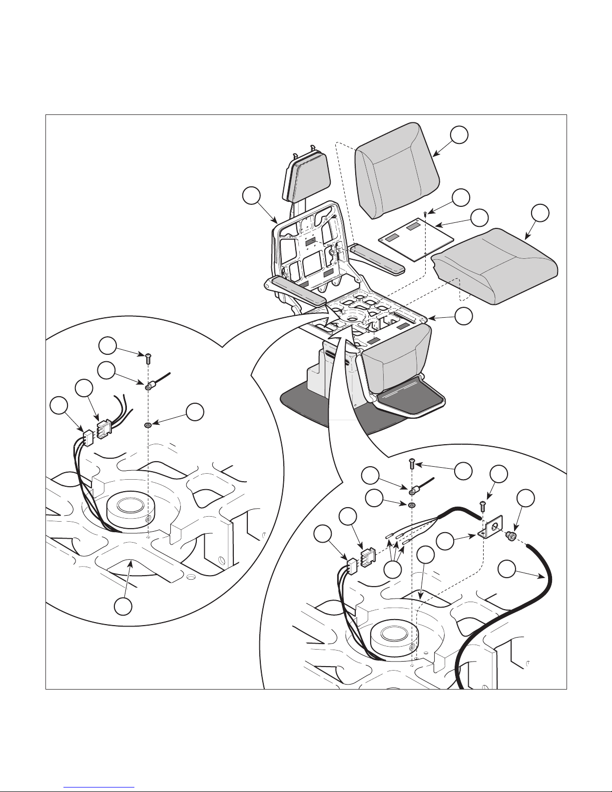
(2) Remove upholstered seat section (1, Figure 4-
7) from seat casting (2) and upholstered back
section (3) from upholstered back casting (4).
4
(3) Remove three screws (5) and seat cover (6)
from seat casting (2).
3
5
6
2
MIDMARK
491
1
Figure 4-7. Wires Disconnection / Connection
© Midmark Corporation 1996 SF-1496 Page 4-7 Printed in U.S.A.
MA313600
SECTION IV
MAINTENANCE / SERVICE
(4) On chairs with Serial Numbers CT-1000 thru
CT-1354 and DG-1000 thru DG-1099, perform
the following steps:
a. Remove screw (7), ground wire (8), and
star washer (9) from seat casting (2).
b. Disconnect wire harness (10) from wire
harness (11).
(5) On chairs with Serial Numbers CT-1355 thru
Present and DG-1100 thru Present, perform
the following steps:
a. Remove screw (12), ground wire (13), and
starwasher (14) from seat casting (2).
b. Disconnect wire harness (15) from wire
harness (16).
NOTE
If back actuator is being discarded, its three wires
can be cut. If the back actuator is being removed for
repair, an amp tool must be used or damage to
socket terminals will result.
c. Using an amp tool, push three socket
terminals (17) from plug (15). See Table
1-2 for special tool.
15
7
14
15
16
18
12
17
11
8
1
9
17
10
4
d. Remove two screws (18) and strain relief
bracket (19) from seat casting (2).
e. Remove strain relief bushing (20) from
strain relief bracket (19).
f. Pull back actuator wires (21) from strain
relief bracket (19).
g. Remove strain relief bushing (20) from
back actuator wires (21).
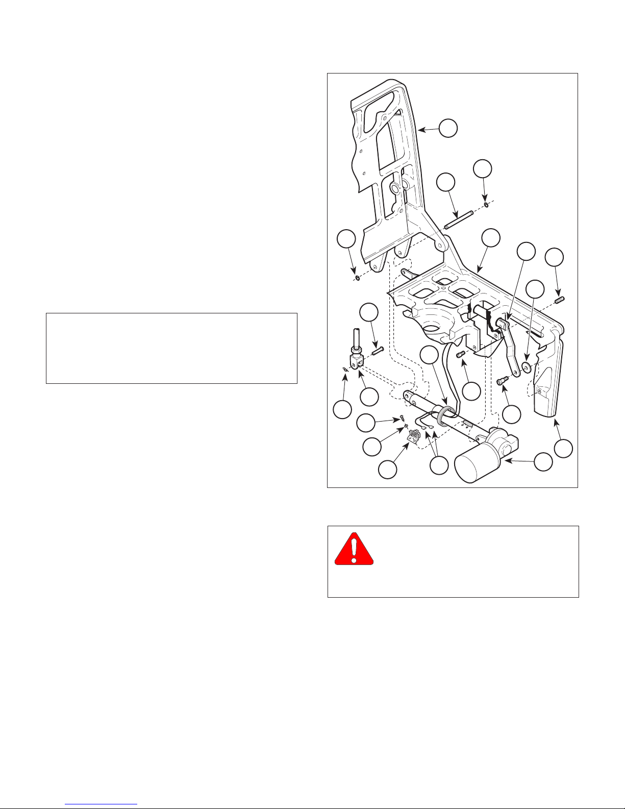
(6) Cut cable tie (1, Figure 4-8) securing limit
switch wires (2) to shaft of back actuator (3).
(7) Remove two screws (4), lockwashers (5), and
separate limit switch bracket (6) from shaft of
back actuator (3).
5
6
Figure 4-8. Back Actuator Removal / Installation
2
3
MA313700
CAUTION
Push arm rests out of the way or support
them while removing clevis pin. The arm
rest will be free to fall, possibly resulting in minor
injury to technician.
(8) Remove rue ring cotter pin (7) and clevis pin (8)
securing linkage assembly (9) to shaft of back
actuator (3).
(9) Remove screw (10) and washer (11) securing
push rod assembly (12) to leg casting (13).
13
© Midmark Corporation 1996 SF-1496 Page 4-8 Printed in U.S.A.
 Loading...