

Page 1
Assembly
Instructions
Stools: Models 425 and 427
MODEL 425
(The above models are shown with optional items attached.)
MODEL 427
Introduction
These assembly instructions are intended to assist you
in assembling Midmark's Model #425 and #427 Stools.
Please follow these instructions to assure proper
assembly.
Unpacking
EQUIPMENT ALERT
To avoid damage, do not use a knife or any other
sharp object for opening cartons.
Assembly
Remove the stool from the carton. Depending on the
optional items that you purchased, assemble the stool
in the following order:
- Optional Lab Height Kit Assembly
- Optional Armrest Assembly
- Optional Backrest Assembly
- Seat Assembly
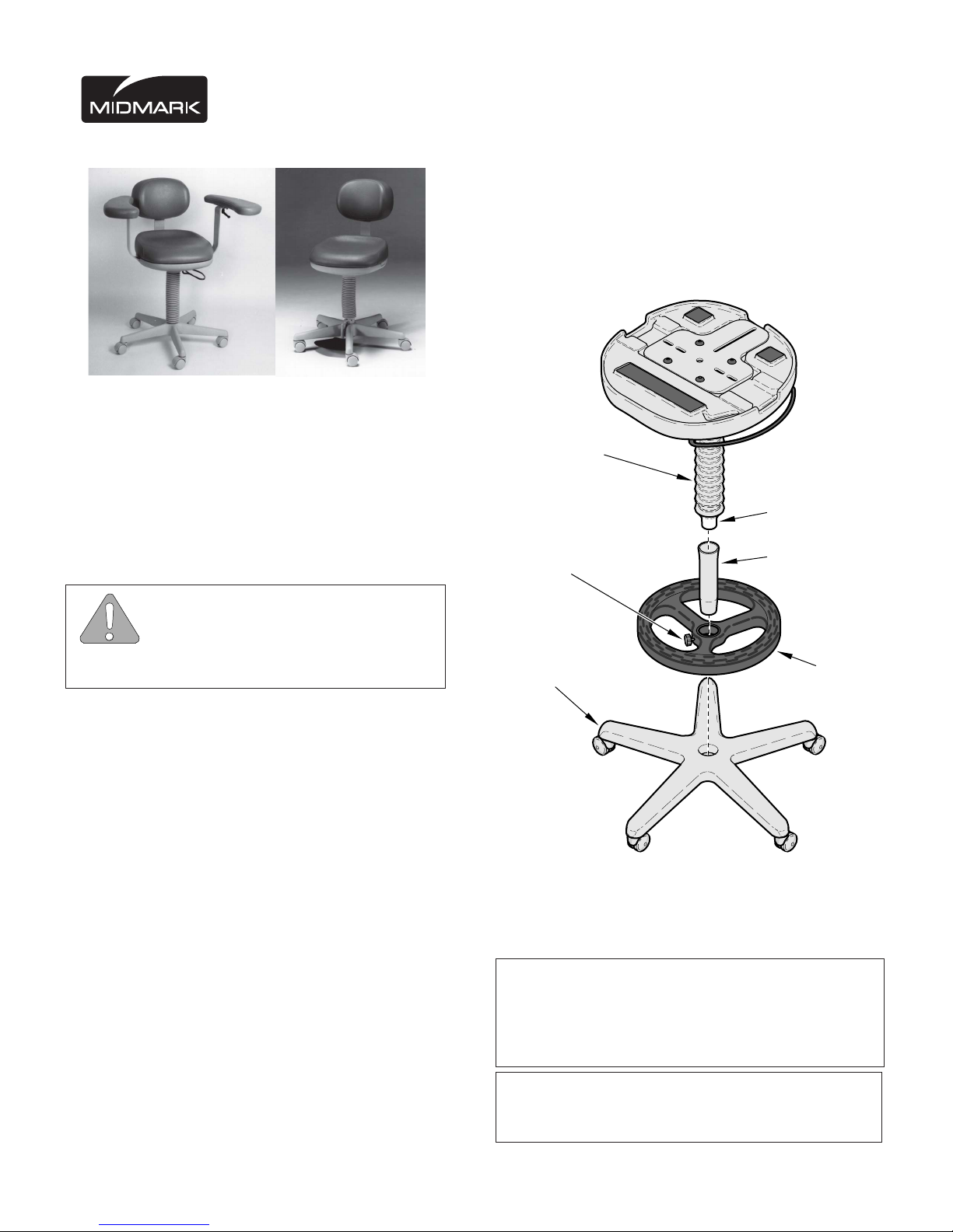
Optional Lab Height Kit Assembly
Place the base stool on its side. Remove the roller
base from the gas cylinder by using a hammer to pound
the roller base from the gas cylinder. To prevent
marking, use a piece of cardboard or wood over the
roller base before striking it. Strike as close to the gas
cylinder as possible and rotate to a different leg with
each blow. Insert extension tube thru the foot ring.
Tighten the knob firmly to prevent the foot ring from
rotating around the tube. Insert the gas cylinder into the
extension tube (see Figure 1). Finally, insert the
extension tube into the roller base.
Bellows
Gas Cylinder
Knob
Roller Base
FIGURE 1
Extension Tube
MA8374i
NOTE
If you have ordered a Lab Height Kit, please assemble the Lab Height Kit to the base stool first. We
suggest that no armrests or backrests be mounted to
the stool during the lab height assembly.
NOTE
The Lab Height Kit cannot be used on 427 Foot
Release Models.
Foot Ring
Sheet
4
1
of
Page 2
Armpad
Angular
Adjustment
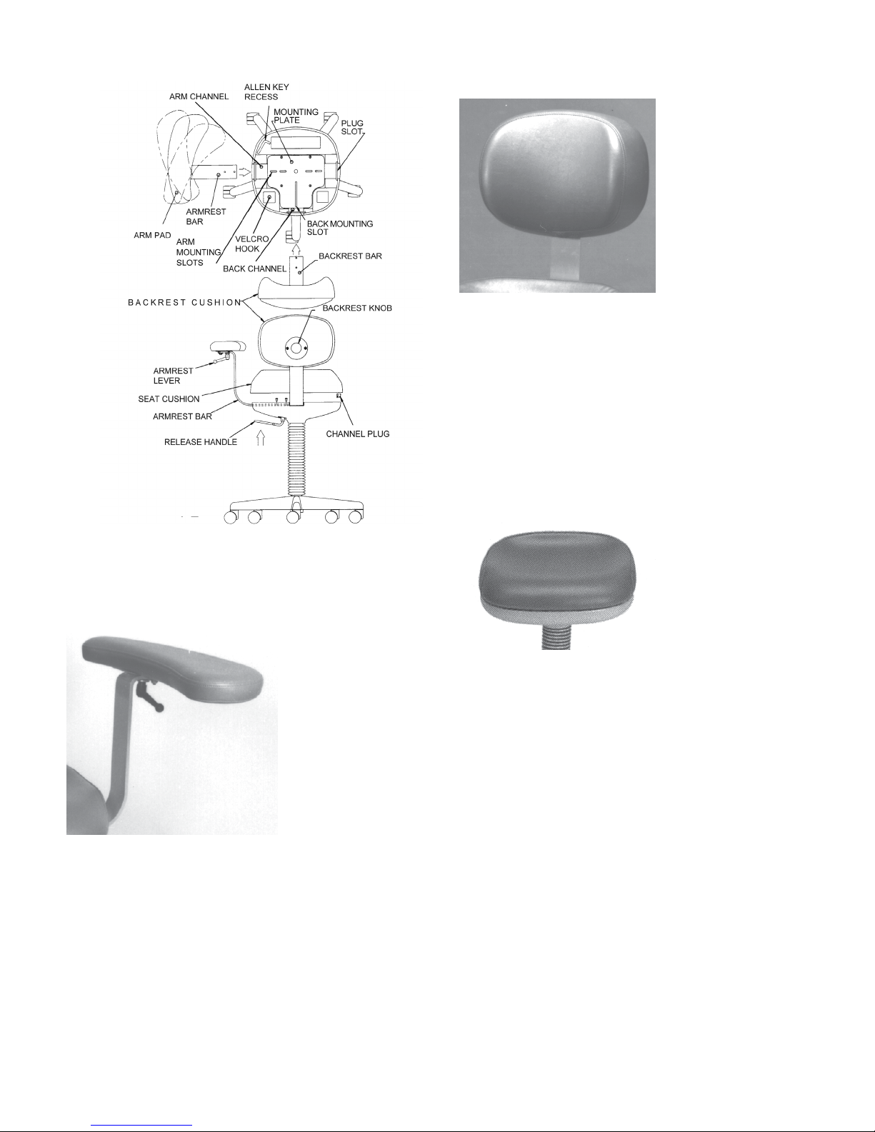
Optional Backrest Assembly
FIGURE 4
Insert the backrest bar into the back channel and under
the mounting plate (see Figure 2). Align the tapped
holes in the backrest bar with the back mounting slot in
the mounting plate. Using the supplied 5/32 Allen Key,
drive the two 1/4 - 20 x 3/8 screws through the mounting plate and into the backrest bar. Tighten the screws
and place the Allen Key into the Allen Key recess.
Seat Assembly
FIGURE 2
Optional Armrest Assembly
FIGURE 3
Insert the armrest bar into the arm channel and under
the mounting plate (see Figure 2). Align the two tapped
holes in the armrest bar with the two arm mounting
slots in the mounting plate. Using the supplied 5/32
Allen Key, drive the two 1/4-20 x 3/8 screws through the
mounting plate and into the armrest bar. Repeat the
above procedure with the other armrest. After tightening the last screw, place the Allen Key into the Allen Key
recess.
Insert the three channel plugs into the plug slots--if
FIGURE 5
needed (see Figure 2). You'll find the channel plugs in
the small parts bag.
Remove the seat cushion from its carton. Align the
three velcro patches on the bottom of the seat cushion
with the three velcro hook patches on the base stool.
Then, place the seat cushion onto the base stool. If the
cushion isn't centered on the base stool, pull the
cushion up and try again.
Sheet
4
2
of
Page 3

Adjustments
Height Adjustment of Stool
Lower the 425 stool by grasping the release handle,
(see Figure 2) and pull up. This will open the valve in
the gas cylinder. The weight of the operator will compress the gas in the cylinder allowing the stool seat to
lower. Once the desired height is reached, release the
handle. The handle will snap back to its original position locking the cylinder's vertical position.
To raise the stool, grasp the handle and pull up. While
holding the handle up, remove the operator's weight
from the stool top. By removing the weight from the
stool top, the compressed gas in the cylinder can exert
enough thrust to force the seat up to the desired
position. When the desired position is reached, release
the handle.
Cleaning
Upholstery
Wash your upholstery weekly with a mild liquid soap and
water mixture, rinse with clear water and dry completely to
remove disinfection cleaner build-up.
Disinfect your upholstery with a solution of standard bleach
and water mixed 1 in 10 (10%) or chlorine based cleaners.
Follow this with a clear water rinse and thorough drying of
material. See current CDC Guideline for Disinfection &
Sterilization in Healthcare Facilities.
To minimize damage caused by disinfectant cleaner residue
build-up, do not allow disinfectants to pool on the upholstery
surface. Once the approved contact time has been obtained,
remove and dry excess liquid remaining on the surface.
Detailed care and maintain instructions are available in your
user guide located on the CD that came with your table or by
referring to
Painted Metal / Plastic Surfaces
Upholstery Care and Maintenance.
In units with the foot release (Model 427), the valve in
the gas cylinder is opened and closed by the action of
the foot pedal instead of the release handle. The valve
is opened by pressing down on the pedal and is closed
by releasing the pedal.
Backrest Adjustment
The backrest has two adjustments: in-and-out and upand-down. Adjust in or out by removing the cushion
and loosening the two 1/4-20 x 3/8 screws with the
supplied 5/32 Allen Key. Position the backrest by
pushing or pulling the backrest bar at the base. Tighten
the two 1/4-20 x 3/8 screws when the desired position
is achieved.
Up-and-down adjustment is obtained by loosening the
backrest knob (turning counterclockwise) and lifting or
lowering the backrest cushion. When the desired
position is reached, tighten the backrest knob (turning
clockwise).
Armrest Adjustment
Each armrest has two adjustments: in-and-out and
angular. In-and-out adjustment is obtained by removing
the cushion and loosening the two 1/4-20 x 3/8 screws
using the supplied Allen Key. Position the armrest by
pushing or pulling the armrest bar at its base. When the
desired position is reached, tighten the two 1/4-20 x 3/8
screws on each arm.
Clean the painted metal and plastic surfaces weekly using a
clean soft cloth, and mild cleaner. Periodic applications of
common furniture wax will ease cleaning, and maintain the
finished luster of the surfaces.
Angular adjustment of the arm pad can be obtained by
turning the arm lever a half-turn in. Adjust the arm pad
to the desired angular position and turn the arm lever a
half-turn out to lock into place.
Sheet
4
3
of
Page 4

SCOPE OF WARRANTY
Midmark Corporation (“Midmark”) warrants to the original retail purchaser that
it will repair or replace components of the domestic and international medical
products manufactured by Midmark (except for components not warranted
under “Exclusions”) that are defective in material or workmanship under
normal use and service. Midmark’s obligation under this warranty is limited to
the repair or replacement, at Midmark’s option, of the applicable components.
This limited warranty shall only apply to defects that are reported to Midmark
within the applicable warranty period and which, upon examination by
Midmark, prove to be defective. This warranty extends only to the first retail
purchaser of a product and is not transferable or assignable.
APPLICABLE WARRANTY PERIOD
The applicable warranty period, measured from the date of delivery to the
original user, shall be one (1) year for all warranted product s and components.
OBTAINING WARRANTY SERVICE
Warranty service must be obtained through either Midmark or an authorized
dealer in the Midmark product line for which warranty service is requested.
Midmark may be contacted for warranty service inquiries or issues via email
at www.midmark.com; by phone at 1-800-MIDMARK; by facsimile at 1-800365-8631; or by mail to Midmark Corporation, 60 Vista Drive, V ersailles, Ohio
45380.
It is the retail purchaser’s obligation to arrange for delivery of a product to
Midmark or one of its authorized dealers for warranty service, which delivery
shall be at retail purchaser’s expense. It is also the retail purchaser’s
obligation to comply with the warranty service instructions provided either by
Midmark or its authorized dealer. The ret ail purchaser must provide Midmark
with completed warranty registration information within thirty (30) days after
purchase in order to obtain the benefits of this warranty .
EXCLUSIONS
This warranty does not cover, and Midmark shall not be liable, for the
following:
(1) defects, damage or other conditions caused, in whole or in part, by
misuse, abuse, negligence, alteration, accident, freight damage, tampering or
failure to seek and obtain repair or replacement in a timely manner;
(2) products which are not installed, used, and properly cleaned and
maintained as required in the Midmark “Installation” and/or “Installation/
Operation Manual” for the applicable product;
(3) products considered to be of a consumable nature;
(4) accessories or parts not manufactured by Midmark;
(5) charges by anyone for adjustments, repairs, replacement parts,
installation or other work performed upon or in connection with such products
which are not expressly authorized in writing in advance by Midmark;
(6) costs and expenses of routine maintenance and cleaning; and
(7) representations and warranties made by any person or entity other than
Midmark.
EXCLUSIVE REMEDY; CONSEQUENTIAL DAMAGES DISCLAIMER:
MIDMARK’S ONLY OBLIGATION UNDER THIS WARRANTY IS THE
REPAIR OR REPLACEMENT OF DEFECTIVE PARTS. MIDMARK SHALL
NOT BE LIABLE FOR AND HEREBY DISCLAIMS ANY DIRECT, SPECIAL,
INDIRECT , INCIDENTAL, EXEMPLARY OR CONSEQUENTIAL DAMAGES
OR DELAYS, INCLUDING, BUT NOT LIMITED T O, DAMAGES FOR LOSS
OF PROFITS OR INCOME, LOSS OF USE, DOWNTIME, COVER AND
EMPLOYEE OR INDEPENDENT CONTRACTOR WAGES, PAYMENTS AND
BENEFITS.
NO AUTHORIZATION
No person or firm is authorized to create or approve for Midmark any other
obligation or liability in connection with the products.
WARRANTY DISCLAIMER
THIS WARRANTY IS MIDMARK’S ONLY WARRANTY AND IS IN LIEU OF
ALL OTHER WARRANTIES, EXPRESS OR IMPLIED. MIDMARK MAKES
NO IMPLIED WARRANTIES OF A N Y KIND INCLUDING ANY IMPLIED
WARRANTIES OF MERCHANTABILITY OR FITNESS FOR A PARTICULAR
PURPOSE. THIS WARRANTY IS LIMITED TO THE REPAIR OR REPLACEMENT OF DEFECTIVE PARTS.
STATUTE OF LIMITATIONS
No action may be brought against Midmark for breach of this limited warranty,
an implied warranty, if any, or for any other claim arising out of or relating to
the products, more than ninety (90) days following expiration of the limited
warranty period.
Midmark Corporation
60 Vista Drive
P .O. Box 286
Versailles, OH 45380-0286
1-800-MIDMARK
Fax 877-249-1793
www.midmark.com
© Midmark Corporation - 1995
003-0458-00 Rev. J (8/15)
Sheet
4
4
of
 Loading...