

Midmark 419-002, 419-001 Parts Manual
419
-001 thru -002
Power Examination Table
Serial Number Prefixes:
AY
NO LONGER IN
Some service parts may not
PRODUCTION
be available for this product!
Service and
Parts Manual
FOR USE BY MIDMARK TRAINED TECHNICIANS ONLY
SF-1493 Part No. 004-0006-00 Rev. M (2/18/13)
419
-001
thru
-002


TABLE OF CONTENTS
Section/Paragraph Page Section/Paragraph Page
IMPORTANT INSTRUCTIONS
General Safety Instructions......................................... ii
Safety Alert Symbols ................................................... ii
Warranty Instructions .................................................. ii
SECTION I GENERAL INFORMATION
Not Available
SECTION II TESTING AND TROUBLESHOOTING
Not Available
SECTION III SCHEDULED MAINTENANCE
Not Available
SECTION IV MAINTENANCE/SERVICE
INSTRUCTIONS
Not Available
SECTION V SCHEMATICS AND DIAGRAMS
5.1 Electrical Schematics / Wiring Diagrams..... 5-1
SECTION VI PARTS LIST
6.1 Introduction ................................................. 6-1
6.2 Description of Columns ............................... 6-1
6.3 Torque Specifications And Important
Assembly Notes ....................................... 6-1
Pictorial Index .............................................. 6 - 2
Upholstery Set ............................................. 6- 3
Upholstery Components .............................6-4.*
Headrest Components................................6-5.*
Back Components...................................... 6-6.*
Back and Foot Actuator Assembly............... 6 -7
Seat Components ......................................6-8.*
Stirrup Assembly ....................................... 6-9.*
Foot Extension Components ....................6-10.*
Footboard Components .............................. 6-11
Covers Components.................................6-12.*
Inner Member Components ........................ 6-13
Base and Tilt Actuator Assembly ............. 6-14.*
Middle Member Components...................... 6-15
Base Components....................................6-16.*
Footswitch Components............................. 6-17
Footswitch Electrical Connections.............. 6-18
Motor and Capacitor Electrical
Connections............................................ 6-19
COMMENTS ............................................................ 7-1
FAX ORDERING FORM .......................................... 7-2
(*) Indicates that there has been a serial number break for the illustration
and that there are additional point page(s) following the original page.
© Midmark Corporation 1996 SF-1493 Rev. 9/00 Page i Printed in U.S.A.
IMPORTANT INSTRUCTIONS
General Safety Instructions
Safety First: The primary concern of Midmark
Corporation is that this table is maintained with the
safety of the patient and staff in mind. To assure that
services and repairs are completed safely and correctly,
proceed as follows:
(1) Read this entire manual before performing any
services or repairs on this table.
(2) Be sure you understand the instructions
contained in this manual before attempting to
service or repair this table.
Safety Alert Symbols
Throughout this manual are safety alert symbols that
call attention to particular procedures. These items are
used as follows:
DANGER
A DANGER is used for an imminently
hazardous operating procedure,
practice, or condition which, if not correctly
followed, will result in loss of life or serious
personal injury.
NOTE
A NOTE is used to amplify an operating procedure,
practice or condition.
Warranty Instructions
Refer to the Midmark “Limited Warranty” printed in the
Installation and Operation Manual for warranty information. Failure to follow the guidelines listed below will
void the warranty and/or render the 419 Power Examination Table unsafe for operation.
• In the event of a malfunction, do not attempt to
operate the table until necessary repairs have been
made.
• Do not attempt to disassemble table, replace malfunctioning or damaged components, or perform
adjustments unless you are one of Midmark’s
authorized service technicians.
• Do not substitute parts of another manufacturer
when replacing inoperative or damaged components.
Use only Midmark replacement parts.
WARNING
A WARNING is used for a potentially
hazardous operating procedure,
practice, or condition which, if not correctly
followed, could result in loss of life or serious
personal injury.
CAUTION
A CAUTION is used for a potentially
hazardous operating procedure, practice,
or condition which, if not correctly followed, could
result in minor or moderate injury. It may also be
used to alert against unsafe practices.
EQUIPMENT ALERT
An EQUIPMENT ALERT is used for an
imminently or potentially hazardous
operating procedure, practice, or condition which, if
not correctly followed, will or could result in serious,
moderate, or minor damage to unit.
© Midmark Corporation 1996 SF-1493 Page ii Printed in U.S.A.

SCHEMATICS AND DIAGRAMS
SECTION V
SCHEMATICS AND DIAGRAMS
SECTION V
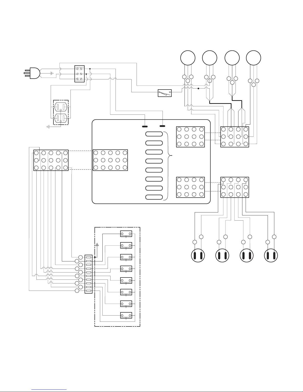
5.1 Electrical Schematics / Wiring
Diagrams
Figure 5-1 illustrates the logic / current flow and wiring
See next page for Illustration
connections between the electrical components in the
table.
© Midmark Corporation 1996 SF-1493 Page 5-1 Printed in U.S.A.
SECTION V
SCHEMATICS AND DIAGRAMS
POWER CORD
GREEN
3 2 1
WHITE
GREEN
RECEPTACLE
2.5 amps MAX.
6 5 4
9 8 7
BASE
ACTUATOR
MOTOR
M
BLACK
WHITE
WHITE
BLACK
10
13
11
14
12
15
BLACK
WHITE
WHITE
3 2 1
INTERFACE
BOARD
6 5 4
9 8 7
RED
WHITE
123
WHITE
J5
BLACK
CONNECTOR
1104 7
2 5 8
3 6 9
FUSES
5 amp , 250 Volt
(015-0346-03)
CONNECTOR
1104 7
2 5 8
3 6 9
J4
J3
WHITE
PAN SAFETY
LIMIT SWITCH (N.O.)
PAN IN = CLOSED CIRCUIT
J6
F8
F7
10
13
11
14
J2
CONNECTOR
12
15
F6
F5
F4
F3
F2
F1
BLACK
FOOT
ACTUATOR
MOTOR
M
RED
WHITE
BLACK
4 6
5
RED
WHITE
BLACK
11
12
11
12
BLACK
WHITE
BACK
ACTUATOR
MOTOR
M
RED
WHITE
BLACK
789
RED
WHITE
BLACK
GRAY
RED
BLACK
WHITE
1104 7
2 5 8
3 6 9
1104 7
2 5 8
3 6 9
RED
WHITE
TILT
ACTUATOR
MOTOR
M
RED
WHITE
BLACK
101112
WHITE
BROWN
YELLOW
BLACK
11
12
11
12
FOOT CONTROL
RED
GRAY
BLUE
PURPLE
YELLOW
BROWN
RED
ORANGE
BLACK
WHITE
GREEN
YELLOW
ORANGE
UP
TABLE
DOWN
15
10
12
4
6
1
3
7
9
2
GREEN
UP
BACK
DOWN
UP
TILT
DOWN
UP
ORANGE
3
1
BASE
CAPACITOR
53-64 M.F.D.
YELLOW
6
4
FOOT
CAPACITOR
27-32 M.F.D.
RED
9
7
BACK
CAPACITOR
41-53 M.F.D.
BLUE
BLUE
12
10
TILT
CAPACITOR
53-64 M.F.D.
FOOT
DOWN
MA312600
Figure 5-1. Electrical Schematic / Wiring Diagram
© Midmark Corporation 1996 SF-1493 Page 5-2 Printed in U.S.A.

SECTION VI
P ARTS LIST
6.1 Introduction
The illustrated parts list provides information for identifying and ordering the parts necessary to maintain the
unit in peak operating condition. Refer to paragraph
1.5 for parts ordering information.
The parts list also illustrates disassembly and assembly
relationships of parts.
6.2 Description of Columns
The
Item
column of the parts list gives a component its
own unique number. The same number is given to the
component in the parts illustration. This allows a part
number of a component to be found if the technician
can visually spot the part on the illustration. The
technician simply finds the component in question on
the illustration and notes the item number of that
component. Then, he finds that item number in the
parts list. The row corresponding to the item number
gives the technician the part number, a description of
the component, and quantity of parts per subassembly.
Also, if a part number is known, the location of that
component can be determined by looking for the item
number of the component on the illustration.
The
Part No.
for that component.
column lists the MIDMARK part number
SECTION VI
PARTS LIST
The
Description
of the component.
The
Qty.
component that is required for the subassembly. The
letters “AR” denote “as required” when quantities of a
particular component cannot be determined, such as:
adhesive.
Bullets [ • ] in the
column show the indenture level of a component. If a
component does not have a bullet, it is a main component of that illustration. If a component has a bullet, it is
a subcomponent of the next component listed higher in
the parts list than itself that does not have a bullet.
Likewise, if a component has two bullets, it is a subcomponent of the next component listed higher in the
parts list than itself that has only one bullet.
column provides a physical description
column lists the number of units of a particular
Part No.
column and the
Description
6.3 Torque Specifications and Important
Assembly Notes
When specific assembly torque specifications, measurements, or procedures have been identified, by our
engineering department, as required to assure proper
function of the unit, those torque specifications measurements, and procedures will be noted on the parts
illustrations. Adherence to these requirements is
essential.
© Midmark Corporation 1996 SF-1493 Printed in U.S.A.
Page 6-1
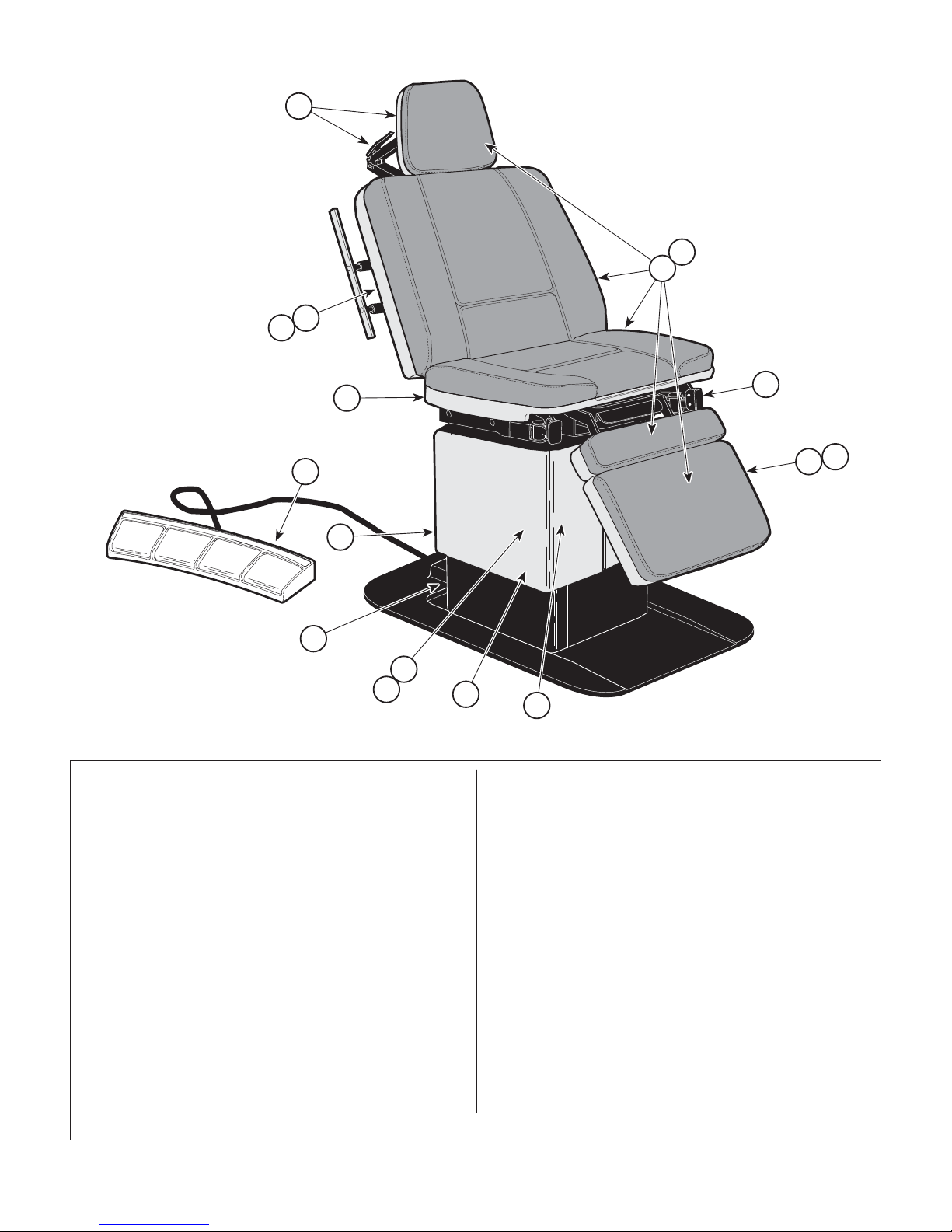
Pictorial Index
5
SECTION VI
PARTS LIST
3
2
1
4
6
15
10
14
11
13
Item Part No. Description Page
419 -002 Examination Table (115 VAC {Serial
Number Perfix "AY"}) ......................... 6-2
1 • • Upholstery Set ................................. 6-3
2 • • Upholstery Components ................... 6-4
3 • • Headrest Components ..................... 6-5
4 • • Back Components ............................ 6-6
5 • • Back and Foot Actuator Assembly ... 6-7
6 • • Seat Components ............................ 6-8
7 • • Stirrup Assembly .............................. 6-9
8 • • Foot Extension Components .......... 6-10
9 • • Footboard Components .................. 6-11
10 • • Covers Components ...................... 6-12
11 • • Inner Member Components ............ 6-13
12 • • Base and Tilt Actuator Assembly .... 6-14
13 • • Middle Member Components .......... 6-15
14 • • Base Components .......................... 6-16
15 • • Footswitch Assembly ..................... 6-17
16 • • Footswitch Electrical Components .. 6-18
16 • • Motor and Capacitor Electrical
Connections .................................... 6-18
Always Specify Model & Serial Number
7
16
12
Item Part No. Description Page
Refer to MEDICAL ACCESSORY BOOK {004-0096-00}
18 • 9A43001 • Chair Arm ...................................... 9A43
19 • 9A51001 • Facial Pad ..................................... 9A51
20 • 9A60001 • Restraint Belts ............................... 9A60
21 • 9A75001 • Caster Base Assembly ................. 9A74
22 • 9A76001 • Base Rail Assembly ...................... 9A76
23 • 9A77001 • I . V. Pole Assembly ....................... 9A77
24 • 9A78001 • Vision Block Screen ...................... 9A78
25 • 9A79001 • Special Procedures Headrest ........ 9A79
26 • 9A81001 • Articulating Armboard .................... 9A81
27 • 9A82001 • Special Procedures Armboard ....... 9A82
28 • 9A83001 • Instrument Tray Assembly ............ 9A83
29 • 9A85001 • Foot Rest Step Assembly .............. 9A85
30 • 9A179001 • Fixed Armboard .......................... 9A179
31 • 9A182001 • Welch Allyn Hanger Assembly ..... 9A182
32 • 9A197001 • Swivel Wheel Caster Assembly ... 9A197
33 • •
34 • 9A74002 •
33 • 9A208002 •
35 • 9A144002
OPTIONAL ACCESSORIES
Knee Crutch Assemblies
s/n AY1000 thru AY2970
s/n AY2970 thru present
•
s/n AY2970 thru present ..............
............. 9A74
.............. 9A208
8
9
MA295800
9A144
© Midmark Corporation 1996 SF-1493 Rev. (4/26/12) Printed in U.S.A.
Page 6-2
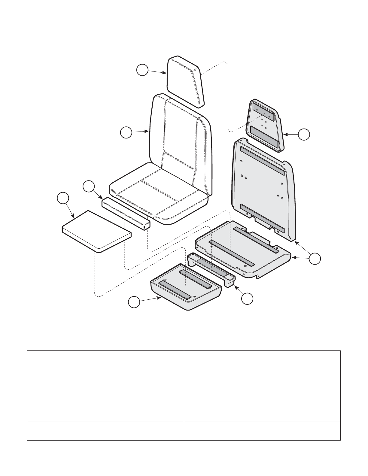
Upholstered Set
SECTION VI
PARTS LIST
1
2
5
3
4
6
8
7
002-0258-XX Upholstery Set (Includes Items 1
1 • 028-0141-XX • Upholstered Headrest ( * Specify
2 • 028-0140-XX • Upholstered Back & Seat ( * Specify
3 • 028-0139-XX • Upholstered Leg ( * Specify Color) ...... 1
4 • 028-0138-XX • Upholstered Footboard ( * Specify
* Click on the Color Selector link above to see available colors.
© Midmark Corporation 1996 SF-1493 Printed in U.S.A.
thru 4 [ * Specify Color]) ........................ 1
Color) .................................................. 1
Color) .................................................. 1
Color) .................................................. 1
Rev. 4/08
MA277701
Item Part No. Description Qty.Item Part No. Description Qty.
5 Headboard Assembly (Refer to "Uphol-
stery Components" Elsewhere) .......... Ref
6 Backrest Assembly (Refer to "Uphol-
stery Components" Elsewhere) .......... Ref
7 Legboard Assembly (Refer to "Uphol-
stery Components" Elsewhere) .......... Ref
8 Footboard Assembly (Refer to "Uphol-
stery Components" Elsewhere) ........... Re
Always Specify Model & Serial Number
Page 6-3
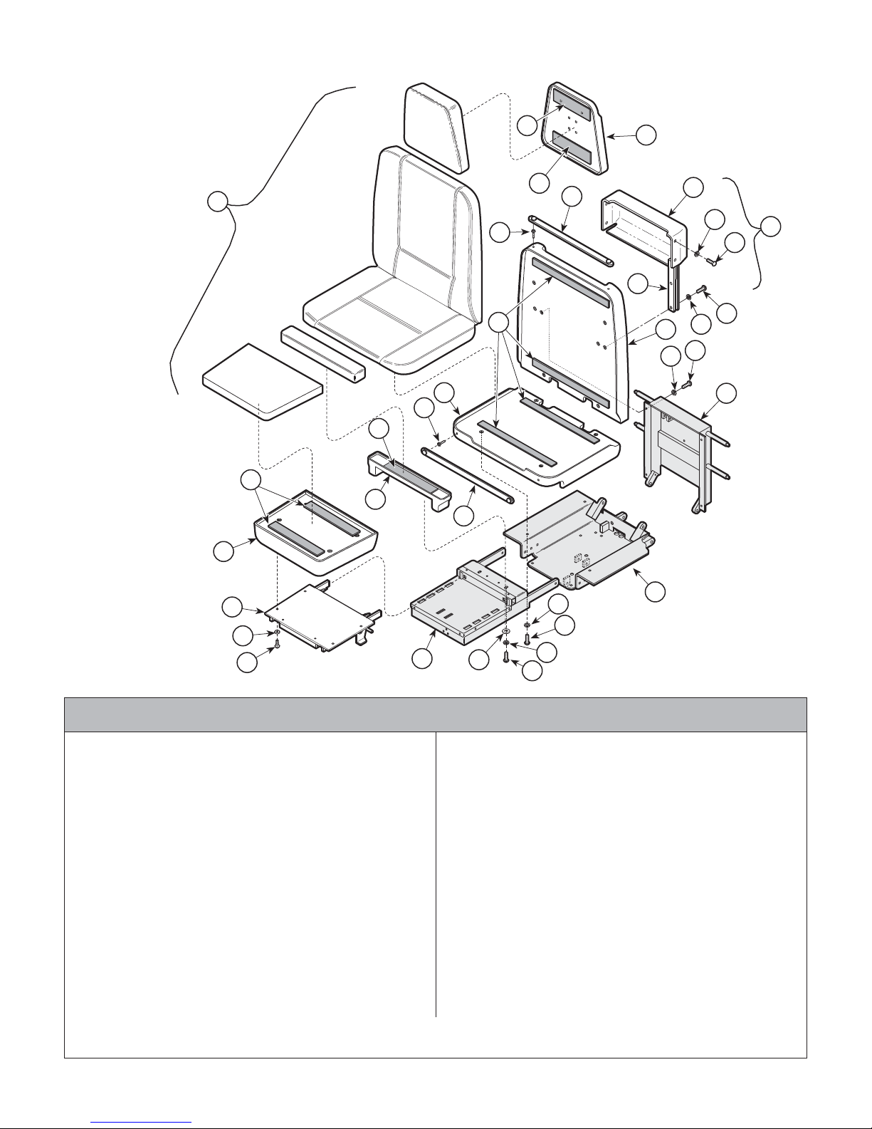
Upholstery Components
SECTION VI
PARTS LIST
2
2
1
6
5
4
9
10
7
11
8
14
13
12
3
18
17
16
15
5
20
21
19
6
22
23
24
25
Used on units with Serial Number AY1000 thru AY1005
1 Upholstery (Refer to "Upholstery
2 053-0131-08 Velcro ................................................... 2
3 Back Weldment (Refer to "Back
4 029-0464-00 Headboard Assembly ............................ 1
5 016-0022-00 Stud ...................................................... 4
6 029-0407-00 Paper Tear Strip .................................... 2
7
N.L.A.
8 •
9 • 053-0209-00 • Paper Roll Holder ................................ 1
10 • 045-0001-39 • Washer ............................................... 4
11 • 040-0008-29 • Screw ................................................. 4
12 040-0008-31 Screw ................................................... 6
13 045-0001-10 Lockwasher .......................................... 6
14 040-0250-63 Screw ................................................... 8
15 045-0001-23 Lockwasher .......................................... 8
•
N.L.A.
N.L.A.
Set" Elsewhere) ................................. Ref
Components" Elsewhere) ................... Ref
Paper Holder Assembly (Includes
Items 8 thru 11) ..................................... 1
• Slide R.H. (Shown) .............................. 1
• Slide L.H. ............................................. 1
"
N.L.A.
Always Specify Model & Serial Number
denotes "No Longer Available
15
30
14
29
26
Item Part No. Description Qty.Item Part No. Description Qty.
16 029-1274-00 Backrest Assembly ............................... 1
17 053-0131-04 Velcro ................................................... 4
18 029-1275-00 Seat Cover Assembly ........................... 2
19 029-0574-00 Leg Board Cover ................................... 1
20 053-0131-08 Velcro ................................................... 1
21 053-0131-02 Velcro ................................................... 2
22 029-0585-00 Footboard Assembly ............................. 1
23 Footboard Weldment (Refer to "Foot-
24 045-0001-03 Lockwasher .......................................... 4
25 040-0250-44 Screw ................................................... 4
26 045-0001-04 Washer ................................................. 2
27 045-0001-00 Washer ................................................. 2
28 040-0010-43 Screw ................................................... 2
29 Foot Extension (Refer to "Foot Extension
30 Seat Weldment (Refer to "Seat
27
28
board Components" Elsewhere) ......... Ref
Components" Elsewhere) ................... Ref
Components" Elsewhere) ................... Ref
MA277702
© Midmark Corporation 1996 SF-1493 Rev. 8/10 Printed in U.S.A.
Page 6-4
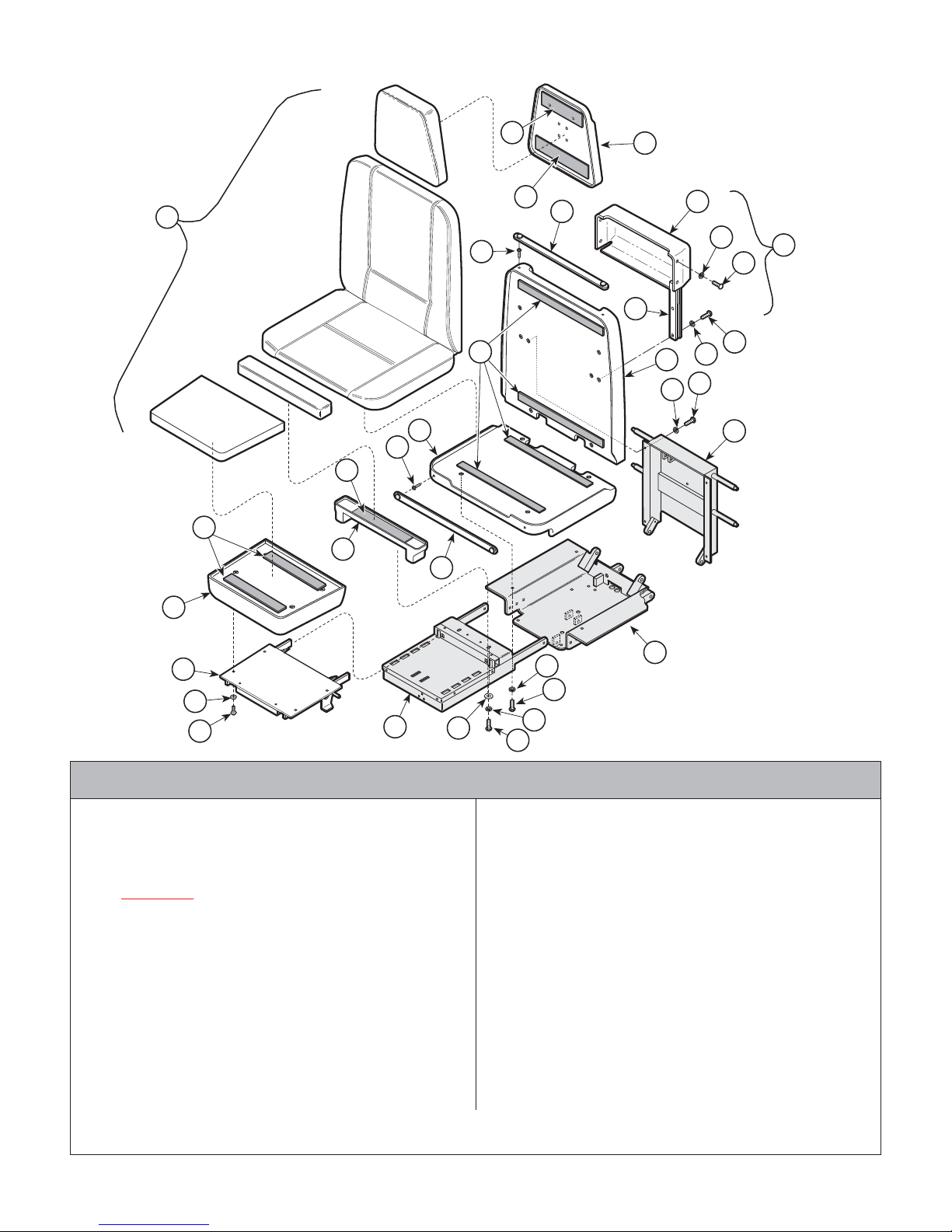
Upholstery Components
SECTION VI
PARTS LIST
2
3
1
6
5
4
9
10
7
11
8
14
13
12
31
18
17
16
15
5
20
21
19
6
22
23
24
25
29
26
Used on units with Serial Number AY1006 thru Present
1 Upholstery (Refer to "Upholstery
2 053-0131-08 Velcro ................................................... 1
3 053-0131-02 Velcro ................................................... 1
4 029-0699-00
5 016-0022-00 Stud ...................................................... 4
6 029-0407-00 Paper Tear Strip .................................... 2
7
N.L.A.
8 •
9 • 053-0209-00 • Paper Roll Holder ................................ 1
10 • 045-0001-39 • Washer ............................................... 4
11 • 040-0008-29 • Screw ................................................. 4
12 040-0008-31 Screw ................................................... 6
13 045-0001-10 Lockwasher .......................................... 6
14 040-0250-63 Screw ................................................... 8
15 045-0001-23 Lockwasher .......................................... 8
16 029-1274-00 Backrest Assembly ............................... 1
•
N.L.A.
N.L.A.
Set" Elsewhere) ................................. Ref
Headboard Assembly ............................ 1
Paper Holder Assembly (Includes
Items 8 thru 11) ..................................... 1
• Slide R.H. (Shown) .............................. 1
• Slide L.H. ............................................. 1
"
N.L.A.
Always Specify Model & Serial Number
denotes "No Longer Available
15
30
14
27
28
Item Part No. Description Qty.Item Part No. Description Qty.
17 053-0131-04 Velcro ................................................... 4
18 029-1275-00 Seat Cover Assembly ........................... 2
19 029-0574-00 Leg Board Cover ................................... 1
20 053-0131-08 Velcro ................................................... 1
21 053-0131-02 Velcro ................................................... 2
22 029-0585-00 Footboard Assembly ............................. 1
23 Footboard Weldment (Refer to "Foot-
board Components" Elsewhere) ......... Ref
24 045-0001-03 Lockwasher .......................................... 4
25 040-0250-44 Screw ................................................... 4
26 045-0001-04 Washer ................................................. 2
27 045-0001-00 Washer ................................................. 2
28 040-0010-43 Screw ................................................... 2
29 Foot Extension (Refer to "Foot Extension
Components" Elsewhere) ................... Ref
30 Seat Weldment (Refer to "Seat
Components" Elsewhere) ................... Ref
31 Back Weldment (Refer to "Back
Components" Elsewhere) ................... Ref
MA277703
Page 6-4.1© Midmark Corporation 1996 SF-1493 Rev. 12/11 Printed in U.S.A.

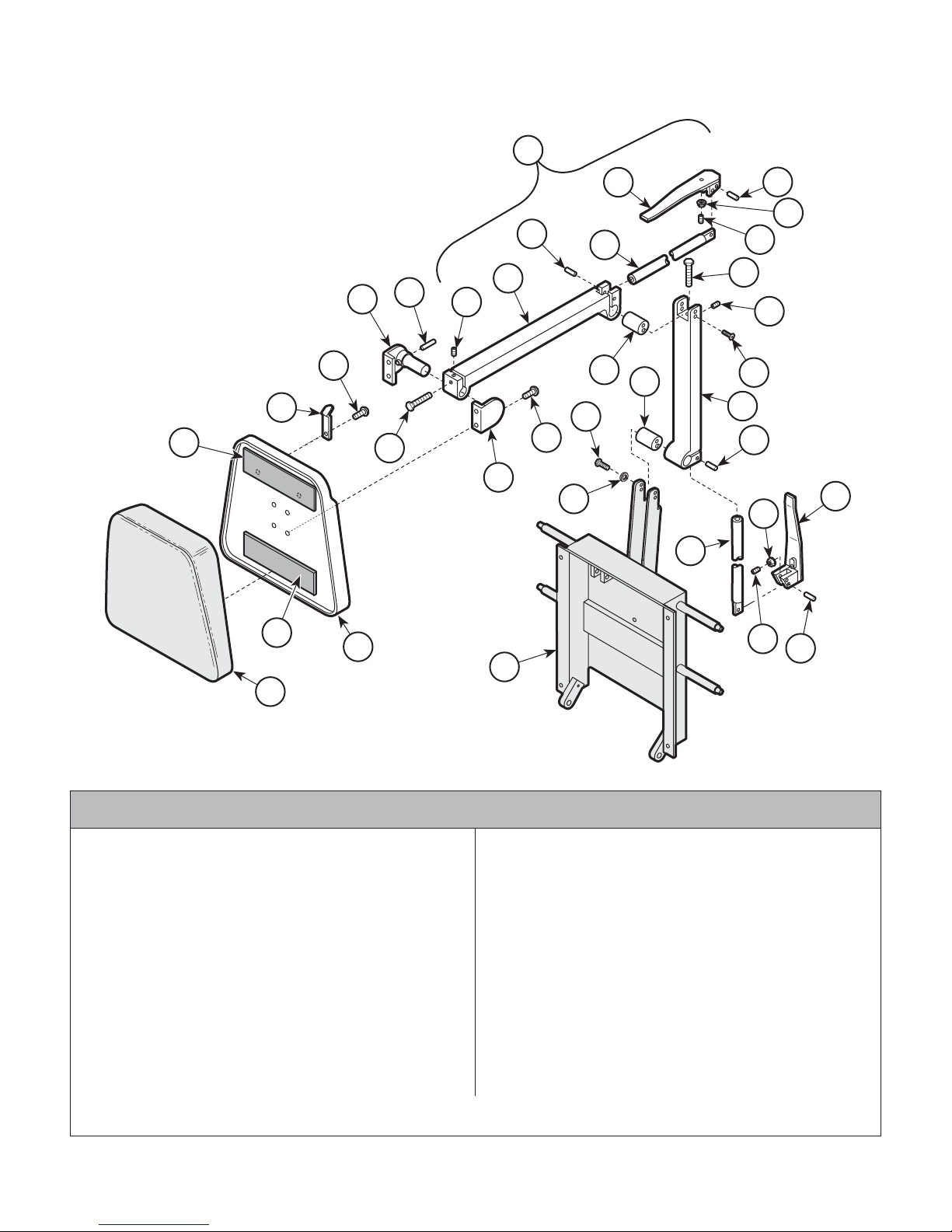
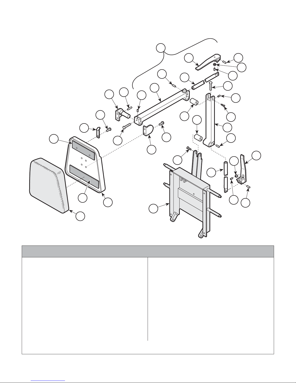
Headrest Components
SECTION VI
PARTS LIST
7
8
14
6
15
5
9
4
12
8
10
16
3
13
11
20
2
18
17
19
1
Used on units with Serial Number AY1000 thru AY1005
1 Upholstered Headrest (Refer to "Uphol
2 053-0131-08 Velcro ................................................... 2
3 Headboard Assembly (Refer to "Uphol-
4 058-0001-00 Bag Clip ................................................. 2
5 040-0006-00 Screw ................................................... 2
6
(N.S.P.)
7•
8•
9•
© Midmark Corporation 1996 SF-1493 Rev. 10/07 Printed in U.S.A.
(N.S.P.)
(N.S.P.)
(N.S.P.)
stered Components" Elsewhere) ........ Ref
stery Components" Elsewhere) .......... Ref
Arm Headlock Assembly (Includes
Items 7 thru 17) ..................................... 1
• Handle ................................................ 1
• Bearing Washer .................................. 2
• Bracket Weldment ............................... 1
Item Part No. Description Qty.Item Part No. Description Qty.
10 •
11 •
12 •
13 •
14 •
15 •
16 •
17 •
18 045-0001-09 Lockwasher .......................................... 2
19 040-0375-25 Screw ................................................... 4
20 Back Weldment (Refer to "Back
(N.S.P.) Denotes "Non Servicable Part"
Always Specify Model & Serial Number
(N.S.P.)
(N.S.P.)
(N.S.P.)
(N.S.P.)
(N.S.P.)
(N.S.P.)
(N.S.P.)
(N.S.P.)
Page 6-5
MA258700
• Headlock Bracket (Large) ................... 1
• Screw ................................................. 4
• Lock Tube ........................................... 1
• Nut ...................................................... 1
• Headrest Top Arm ............................... 1
• Headlock Assembly ............................ 1
• Retaining Ring ..................................... 2
• Headrest Bottom Arm .......................... 1
Components" Elsewhere) ................... Ref
Headrest Components
SECTION VI
PARTS LIST
10
16
17
18
17
20
13
7
6
5
4
2
11
12
15
24
27
9
19
21
12
22
23
14
8
26
16
18
25
2
3
19
17
28
1
Used on units with Serial Number AY1006 thru AY3704
1 Upholstered Headrest (Refer to "Uphol
2 053-0131-08 Velcro ................................................... 2
3 Headboard Assembly (Refer to "Uphol-
4 058-0001-03 Bag Clip ................................................. 2
5 040-0006-00 Screw ................................................... 2
6 029-0103-00 Headboard Pivot Assy. (Incl. Item 7) ..... 1
7 • 042-0001-00 • Roll Pin ................................................ 1
8 030-0124-00 Headboard Pivot Assembly ................... 1
9 040-0010-23 Screw ................................................... 4
10 029-1100-00 Two Arm Headlock Assembly (Includes
11 •
12 •
13 •
© Midmark Corporation 1996 SF-1493 Rev. 10/07 Printed in U.S.A.
(N.S.P.)
(N.S.P.)
(N.S.P.)
stered Components" Elsewhere) ........ Ref
stery Components" Elsewhere) .......... Ref
Items 11 thru 25) ................................... 1
• Screw ................................................. 1
• Set Screw ........................................... 2
• Headlock ............................................. 1
Item Part No. Description Qty.Item Part No. Description Qty.
14 •
15 •
16 •
17 •
18 •
19 •
20 •
21 •
22 •
23 •
24 •
25 •
26 045-0001-05 Lockwasher .......................................... 4
27 040-0250-10 Bolt ....................................................... 4
28 Back Weldment (Refer to "Back
(N.S.P.) Denotes "Non Servicable Part"
Always Specify Model & Serial Number
(N.S.P.)
(N.S.P.)
(N.S.P.)
(N.S.P.)
(N.S.P.)
(N.S.P.)
(N.S.P.)
(N.S.P.)
(N.S.P.)
(N.S.P.)
(N.S.P.)
(N.S.P.)
Page 6-5.1
MA258802
• Dowel Pin ............................................ 2
• Pivot Bar ............................................. 1
• Head Pivot Handle ............................... 2
• Dowel Pin ............................................ 4
• Nut ...................................................... 2
• Screw ................................................. 2
• Draw Bar ............................................. 1
• Bolt ..................................................... 1
• Screw ................................................. 4
• Base Headlock .................................... 1
• Pivot Bar ............................................. 1
• Draw Bar ............................................. 1
Components" Elsewhere) ................... Ref
Headrest Components
SECTION VI
PARTS LIST
10
16
17
18
17
20
13
6
5
7
12
15
24
4
1
11
9
19
21
12
22
23
14
8
16
26
18
25
2
3
19
17
27
28
Used on units with Serial Number AY3705 thru AY3805
1 053-0131-08 Velcro ................................................... 1
2 053-0131-02 Velcro ................................................... 1
3 Headboard Assembly (Refer to "Uphol-
4 058-0001-03 Bag Clip ................................................. 2
5 040-0006-00 Screw ................................................... 2
6 029-0103-02 Headboard Pivot Assembly ................... 1
7 • 042-0001-00 • Roll Pin ................................................ 1
8 030-0124-03 Headboard Pivot Assembly ................... 1
9 040-0010-23 Screw ................................................... 4
10 029-1100-02 Two Arm Headlock Assembly (Includes
11 •
12 •
13 •
14 •
© Midmark Corporation 1996 SF-1493 Rev. 10/07 Printed in U.S.A.
(N.S.P.)
(N.S.P.)
(N.S.P.)
(N.S.P.)
stery Components" Elsewhere) .......... Ref
Items 11 thru 25) ................................... 1
• Screw ................................................. 1
• Set Screw ........................................... 2
• Headlock ............................................. 1
• Dowel Pin ............................................ 2
Item Part No. Description Qty.Item Part No. Description Qty.
15 •
16 •
17 •
18 •
19 •
20 •
21 •
22 •
23 •
24 •
25 •
26 040-0250-88 Screw ................................................... 4
27 Back Weldment (Refer to "Back
28 Upholstered Headrest (Refer to "Uphol
(N.S.P.) Denotes "Non Servicable Part"
Always Specify Model & Serial Number
(N.S.P.)
(N.S.P.)
(N.S.P.)
(N.S.P.)
(N.S.P.)
(N.S.P.)
(N.S.P.)
(N.S.P.)
(N.S.P.)
(N.S.P.)
(N.S.P.)
Page 6-5.2
MA258801
• Pivot Bar ............................................. 1
• Head Pivot Handle ............................... 2
• Dowel Pin ............................................ 4
• Nut ...................................................... 2
• Screw ................................................. 2
• Draw Bar ............................................. 1
• Bolt ..................................................... 1
• Screw ................................................. 4
• Base Headlock .................................... 1
• Pivot Bar ............................................. 1
• Draw Bar ............................................. 1
Components" Elsewhere) ................... Ref
stered Components" Elsewhere) ........ Ref
 Loading...