

Midmark 417-001, 417, 417-003 Parts Manual
417
-001 thru -003
Power Podiatry Treatment Table
Serial Number Prefixes:
BP, EP & V
Service and
Parts Manual
417
-001
thru
-003
FOR USE BY MIDMARK TRAINED TECHNICIANS ONLY
SF-1399 Part No. 003-0709-00 Rev. R (11/25/09)


TABLE OF CONTENTS
Section/Paragraph Page Section/Paragraph Page
IMPORTANT INSTRUCTIONS
General Safety Instructions......................................... iii
Warnings ..................................................................... iii
Warranty Instructions .................................................. iii
SECTION I GENERAL INFORMATION
1.1 Scope of Manual ......................................... 1-1
1.2 How to Use Manual ..................................... 1-1
1.3 Description of 417 Power Podiatry
Treatment Chair ....................................... 1-1
1.4 Specifications ............................................. 1-5
1.5 Parts Replacement Ordering ....................... 1-5
1.6 Special Tools .............................................. 1-6
SECTION II TESTING AND TROUBLESHOOTING
2.1 Operational Test .......................................... 2-1
2.2 Troubleshooting Procedures ........................ 2-3
SECTION III SCHEDULED MAINTENANCE
3.1 Scheduled Maintenance .............................. 3-1
SECTION IV MAINTENANCE/SERVICE
INSTRUCTIONS
4.1 Introduction ................................................. 4-1
4.2 Reinitialization Procedure ............................ 4-1
4.3 Table Top Removal / Installation ................. 4-2
4.4 Shrouds Removal / Installation .................... 4-3
4.5 Power Cord Removal / Installation............... 4-4
4.6 Control Disable Switch Removal /
Installation ............................................... 4-5
4.7 Hand Control Plug-In Port Removal /
Installation ............................................... 4-5
4.8 PC Control Board / Program PC Board
Removal / Installation .............................. 4-6
4.9 Foot Control Plug-In Port Removal /
Installation ............................................... 4-7
4.10 Base Down Limit Switch Removal /
Installation ............................................... 4-8
4.11 Actuator Motor / Actuator Brake
Removal / Installation .............................. 4-8
4.12 Base Actuator Assembly Removal /
Installation ............................................. 4-10
4.13 Gas Spring Removal / Installation ............. 4-12
4.14 Base Capacitor Removal / Installation ....... 4-13
4.15 Tilt Actuator Assembly Removal /
Installation ............................................. 4-14
4.16 Tilt Capacitor Removal / Installation .......... 4-15
4.17 Back Actuator Assembly Removal /
Installation ............................................. 4-16
4.18 Back Capacitor Removal / Installation ....... 4-18
4.19 Arm Rest Adjustment ................................ 4-18
4.20 Foot Extension Brake Lever Adjustment ... 4-19
4.21 Hand Control Panel Or Interface Board
Removal / Installation ............................ 4-19
4.22 Typical Foot Pedal Foot Switch Removal /
Installation ............................................. 4-20
4.23 Typical Foot Switch Removal /
Installation ............................................. 4-21
4.24 Foot Control Interface Board Removal /
Installation ............................................. 4-21
4.25 Plastic Foot Section Removal /
Installation ............................................. 4-22
4.26 Plastic Back Section Removal /
Installation ............................................. 4-23
4.27 Plastic Seat Section Removal /
Installation ............................................. 4-24
4.28 Base Up Limit Switch Removal /
Installation / Adjustment ......................... 4-25
4.29 Foot Extension Removal /
Installation .............................................. 4-26
SECTION V SCHEMATICS AND DIAGRAMS
5.1 Electrical Schematics / Wiring Diagrams ..... 5-1
5.2 Audible Signal Guide Chart ......................... 5-9
SECTION VI PARTS LIST
6.1 Introduction ................................................. 6-1
6.2 Description of Columns ............................... 6-1
Pictorial Index ............................................ 6-2.*
Upholstery Set (Standard) .......................... 6-3.*
Back Section Components ......................... 6-4.*
Seat Section Components ........................... 6-5
Actuator Assembly (Domestic) .................. 6-6.*
Actuator Assembly (Canadian) .................. 6-7.*
Foot Section Components ........................... 6-8
Upper Chair Electrical Components
(Domestic) .............................................. 6-9.*
Upper Chair Electrical Components
(Canadian) ............................................ 6-10.*
Lower Chair Electrical Components .......... 6-11.*
Power Base Assembly ............................. 6-12.*
Base Sub-Assembly ................................ 6-13.*
Base Actuator Assembly ........................ 6-14.*
Foot Control Assembly ............................. 6-15.*
COMMENTS ............................................................ 7-1
FAX ORDERING FORM .......................................... 7-2
(*) Indicates that there has been a serial number break for the illustration
and that there are additional point page(s) following the original page.
© Midmark 1994 SF-1399 Rev. 12/03 Page i Printed in U.S.A.

IMPORTANT INSTRUCTIONS
General Safety Instructions
Safety First: The primary concern of Midmark
Corporation is that this treatment chair is maintained
with the safety of the patient and staff in mind. To
assure that services and repairs are completed safely
and correctly, proceed as follows:
(1) Read this entire manual before performing any
services or repairs on this chair.
(2) Be sure you understand the instructions
contained in this manual before attempting to
service or repair this chair.
Warnings
Throughout this manual are Note, Caution, and Danger
paragraphs that call attention to particular procedures.
These items are used as follows:
NOTE
A note is used to amplify an operating procedure,
practice or condition.
Warranty Instructions
Refer to the Midmark “Limited Warranty” printed on the
back cover of the Installation and Operation Manual for
warranty information. Failure to follow the guidelines
listed below will void the warranty and/or render the 417
Power Podiatry Treatment Chair unsafe for operation.
• In the event of a malfunction, do not attempt to
operate the chair until necessary repairs have been
made.
• Do not attempt to disassemble chair, replace malfunctioning or damaged components, or perform
adjustments unless you are one of Midmark’s
authorized service technicians.
• Do not substitute parts of another manufacturer
when replacing inoperative or damaged components.
Use only Midmark replacement parts.
CAUTION
!!
not correctly followed, could result in equipment
damage.
A CAUTION is used for an operating
procedure, practice, or condition which, if
DANGER
!!
which, if not correctly followed, could result in
loss of life or serious personal injury.
A DANGER is used for an operating
procedure, practice, or condition
© Midmark 1994 SF-1399 Page iii Printed in U.S.A.

© Midmark 1994 SF-1399 Page iv Printed in U.S.A.

SECTION I
GENERAL INFORMATION
SECTION I
GENERAL INFORMATION
1.1 Scope of Manual
This manual contains detailed troubleshooting, scheduled maintenance, maintenance, and service instructions for 417 Power Podiatry Treatment Chair. This
manual is intended to be used by Midmark’s authorized
service technicians.
1.2 Description Of 417 Power Podiatry
Treatment Chair
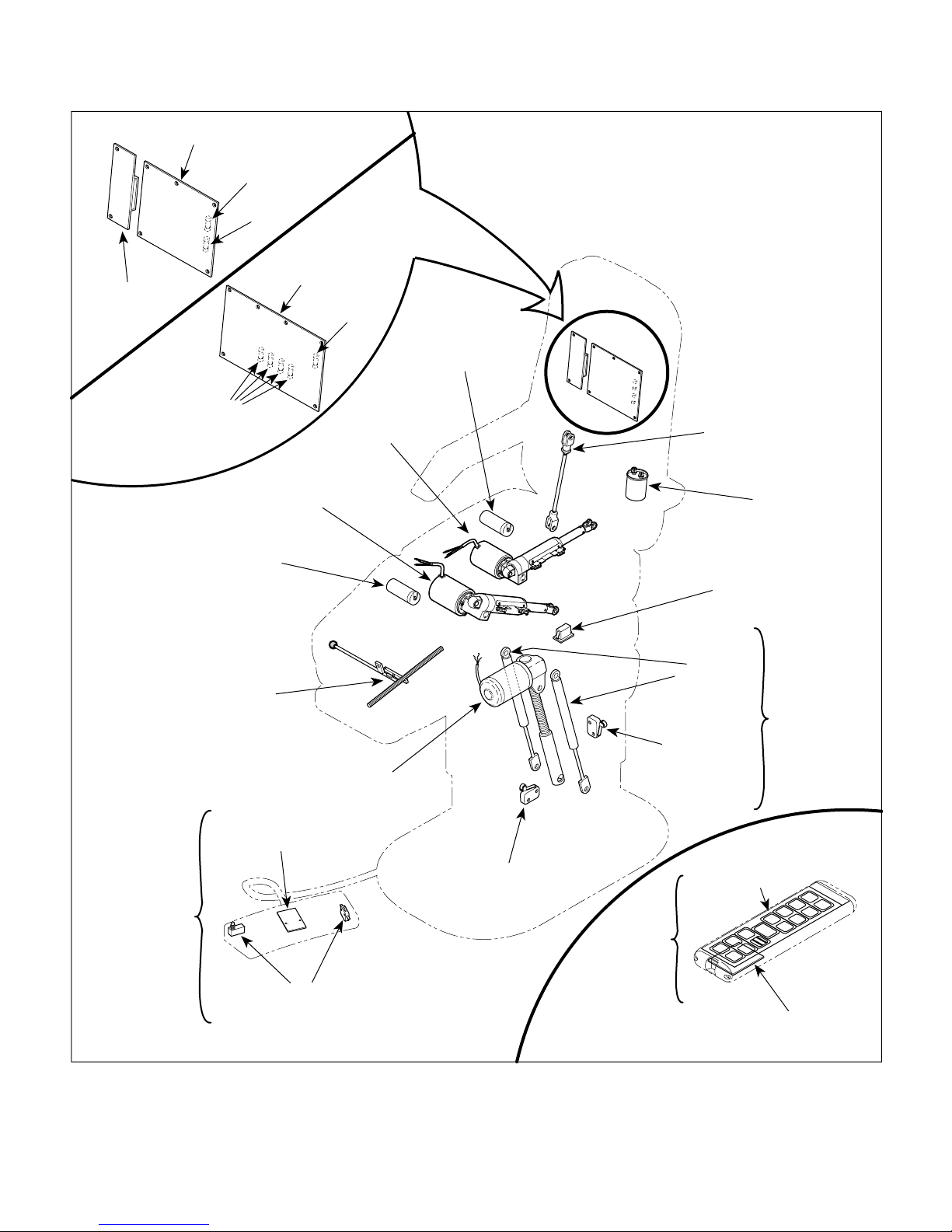
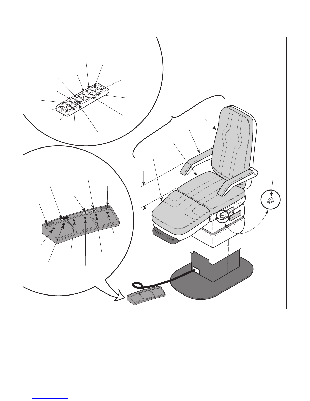
A. General Description (See Figure 1-1).
The 417 Power Podiatry Treatment Chair is an examination chair designed specifically for performing general
podiatric examinations and minor podiatric procedures
(Podiatry - treatment of foot ailments).
The major serviceable components of the chair are the
arm casting linkage assembly, back actuator capacitor,
back actuator assembly, tilt actuator capacitor, tilt
actuator assembly, foot extension brake assembly,
base capacitor, base actuator assembly, gas spring(s),
base subassembly, base down limit switch, base up
limit switch, PC control board, PC program board (a new
style PC control board is now being used which combines the PC control board and PC program board
together into one board), 0.5 amp fuse & 20 amp fuses
for old style PC control board and 0.125 amp & 5 amp
fuses for new style PC control board, control disable
switch, foot control which includes foot switches and
foot control interface board, and hand control which
includes hand control panel and hand control interface
board.
B. Theory of Operation (See Figures 5-1 thru 5-4 for
electrical schematic / wiring diagram)
115 VAC is supplied directly to the PC control board and
to the two electrical outlets.
Power:
The 115 VAC that is supplied to the PC control board is
applied across two types of fuses; a 20 amp fuse and a
0.5 or 0.125 amp fuse (0.5 amp fuse is used on old style
PC control board and 0.125 amp fuse is used on new
style PC control board). 115 VAC is applied across a 20
amp fuse and supplies power to the contacts of the
normally open actuator relays (there is one 20 amp fuse
on the old style PC control board which protects all eight
actuator relays. There are four 5 amp fuses on the new
style PC control board; one for each actuator motor).
This power is used to run an actuator assembly when its
relay is energized. There are two relays per actuator
assembly; one for each direction. There are two relays
on the PC control board for a foot actuator assembly,
which are not used by the 417 model. However, this PC
control board is used by another model, the 414, which
has a foot actuator assembly and uses the relays. 115
VAC is also applied across the 0.5 amp fuse or 0.125
amp fuse (0.5 amp fuse is used on old style PC control
board and 0.125 amp fuse is used on new style PC
control board) to the PC control board transformer. The
transformer and some associated follow on circuitry
reduce the 115 VAC to a +5 VDC output and a +12 VDC
output. Both voltages are used to power circuitry on the
PC control board and PC program board. On the new
PC control board, there is a green "BOARD FAIL
L.E.D.". If the L.E.D. is flashing, normal operation is
being indicated. If the L.E.D. is not flashing, the PC
control board is malfunctioning. Loss of power or blown
fuses can also cause the green L.E.D. to not flash.
Actuators:
• On older units (before SN BP7668) both Back and Tilt
actuators contain a pivot point on the end of the ball
screw. If an actuator is run to the end of its stroke
(mechanical home position), the ball screw shaft spins
inside the nut, allowing the actuator to run without
damaging or advancing the nut.
• On present units (after SN BP7668) both the Back and
Tilt actuators have limit switches to prevent overextending or retracting the actuator. Should the actuator
reach the maximum extended or minimum retracted
travel the specific limit switch contacts will Open,
removing power from the actuator motor. This prevents
the actuator from over-extending or over-retracting.
• All the actuator motors have a normally closed,
thermal overload switch which will open if the actuator
assembly is run continuously and overheats.
The actuator motor was not designed for continuous
operation. The normal cool off period for the thermal
overload switches is 10 - 20 minutes.
Normal Operation:
When a function switch is pressed on either the hand
control or foot control, an interface board, located in the
foot control or hand control, encodes the signal and
sends it to the PC control board. The PC control board
decodes the information and energizes the relay of the
© Midmark 1994 SF-1399 Rev. 12/03 Page 1-1 Printed in U.S.A.
SECTION I
GENERAL INFORMATION
PC CONTROL
PC PROGRAM
BOARD
BOARD
(0.5 Amp.)
(4) FUSE
(5 Amp.)
TILT ACTUATOR
CAPACITOR
OLD STYLE
(1) FUSE
(1) FUSE
(20 Amp.)
PC CONTROL
BOARD
TILT ACTUATOR
ASSEMBLY
NEW STYLE
(1) FUSE
(0.125 Amp.)
BACK ACTUATOR
ASSEMBLY
BACK ACTUATOR
CAPACITOR
ARM CASTING
LINKA GE ASSEMBLY
BASE
CAPACITOR
CONTROL
DISABLE
SWITCH
FOOT EXTENSION
BRAKE ASSEMBLY
FOOT
CONTROL
BASE ACTUATOR
FOOT CONTROL
INTERFACE BOARD
FOOT
SWITCHES
ASSEMBLY
BASE UP
LIMIT SWITCH
Figure 1-1. Major Components
HAND
CONTROL
GAS
SPRING(S)
BASE DOWN
LIMIT SWITCH
HAND CONTROL
PANEL
POSITION
1
POSITION
3
POSITION
4
BASE
SUBASSEMBLY
MIDMAR
T
ABLE
UP
BA
T
ABLE
DO
CK
UP
WN
BA
TIL
DO
CK
UP
T
WN
FOO
TIL
DO
UP
T
T
WN
FOO
DO
ST
T
WN
OP
AUT
RETURN
O
POSITION
POSITION
2
HAND CONTROL
INTERFACE BOARD
MA247301i
© Midmark 1994 SF-1399 Rev. 12/03 Page 1-2 Printed in U.S.A.

SECTION I
GENERAL INFORMATION
selected function. The 115 VAC that is continuously
supplied to the normally open (N.O.) contacts of the
relay is now applied across the actuator assembly motor
windings, causing the actuator assembly to run. There
is a diagnostic L.E.D. in each relay circuit. When a
relay coil is energized, an L.E.D. that is in the same
circuit illuminates, indicating that there is power at the
relay's coil and the PC control board is working properly.
When the PC control board receives a function signal
from a hand control or foot control, the microprocessor
on the PC control board does several things; it continuously monitors the current draw of the running actuator
assembly motor (this is important because different
patient loads affect the amount of current drawn by the
motor as well as its speed - meaning monitoring current
draw can let the PC control board calculate an actuator
assembly's speed). The PC control board also keeps
track of how long an actuator assembly's relay has been
energized (how long actuator assembly motor has been
running). By comparing the current draw of the running
actuator motor and the time period that an actuator
assembly's relay has been energized, against an onboard data base, the PC control board can determine
how far, in its range of motion, an actuator assembly
has traveled. The PC control board records this positional information in its memory. The PC control board
continuously calculates an actuator assembly's position
and stores that information in memory for future use.
Also, if the current draw of an actuator assembly
exceeds a predetermined level for more than 0.5
seconds, the PC control board shuts down the actuator
assembly, until the footswitch/button is released and
depressed again.
When an operator selects a function, the PC control
board calculates the maximum run time that it will take
the actuator assembly to reach the end of its travel
range. If the operator holds down the function button
longer than the maximum run time, the PC control board
will deenergize the relay of the actuator assembly when
the maximum run time is reached, causing the actuator
assembly motor to stop running. This prevents excessive wear on an actuator assembly due to a switch
sticking or an operator continuously holding down a
function switch.
When a function (this is true for only for a few of the
functions) is reselected, after its actuator assembly has
been stopped by the PC control board because it
reached its maximum run time, the PC control board will
allow the actuator assembly to run for 2 seconds before
deenergizing its relay. This allows the mechanical
"home" position of the actuator assembly to be synchronized with the PC control board's software "home"
position.
The TABLE UP and TABLE DOWN function works
slightly different however; it uses a limit switch to stop
the actuator assembly when it reaches its end of travel
instead of letting the PC board stop it. This prevents
wear of the base actuator assembly by not allowing it to
freewheel. The base actuator assembly sees much
heavier loads on it than do the other actuator assemblies. If the base actuator assembly were allowed to
freewheel, the life of the actuator assembly would be
greatly reduced. The base up and base down limit
switch is a normally closed switch. When either limit
switch is tripped, the circuit that provides power to the
base actuator assembly for the up or down function is
opened, causing the base actuator assembly to stop.
Programmed Positions:
The operator positions the chair into a position he/she
would like to store into memory. When the PROGRAM
button is pressed and held for 0.2 seconds for old style
PC control board or 1 second for new style PC control
board, the PC control board is in program mode and is
ready to store a position into memory. Then, when one
of the two program position buttons ("1" or "2") on the
foot control or one of the four program position buttons
("1", "2", "3", or "4") on the hand control is pressed, the
position of the chair is stored into the PC control board's
memory. The operator has five seconds in which to
select a programmed position button. After five seconds, the PC control board cancels the program mode.
Also, if any buttons other than the program position
buttons "1", "2", "3", or "4" are pressed, the program
mode is canceled. The PC control board stores the
chair's position which has been calculated and stored in
the PC control boards memory as described in the
"normal operation" of a function.
When an operator presses a programmed position
button, the PC control board determines which functions
need to move and energizes the relays for the actuator
assemblies of those functions. The PC control board
uses the method described in "normal operation" to
determine when an actuator assembly of a function has
reached its programmed position. When an actuator
assembly of a function reaches its position, its relay is
deenergized. This continues until all actuator assemblies of affected functions have reached their position.
If the operator wishes to stop the chair, for any reason,
before all functions have reached their programmed
position, the STOP button may be pressed. When the
© Midmark 1994 SF-1399 Rev. 12/03 Page 1-3 Printed in U.S.A.

SECTION I
GENERAL INFORMATION
STOP button is pressed, the PC control board immediately deenergizes all relays, causing the chair to stop.
The STOP button overrides all other commands.
When a programmed position button is selected, it can
be pressed and then released; it does not need to be
held down. However, there is a selector switch; S1 on
the old style PC control board and SW2-4 on new style
PC control board, that can be switched to change this.
Then the programmed position button must be pressed
and held until the chair reaches its programmed position;
if the button is released, the chair will stop moving. The
switch (S1) works as follows: when the switch S1 is
pushed in, the programmed position button can be
pressed and released. When the switch S1 is pulled
out, the programmed position button must be pressed
and held. Switch SW2-4 works as follows: when switch
is ON, programmed position buttons can be pressed and
released. When switch SW2-4 is OFF, programmed
position buttons must be pressed and held.
Auto Return Function Operation:
When the operator presses the AUTO RETURN button,
the PC control board determines which functions need to
move and energizes the relays for the actuator assemblies of those functions. The PC control board uses the
method described in "normal operation" to determine
when an actuator assembly of a function has reached
the mechanical home position. When an actuator
assembly of a function reaches its home position, its
relay is deenergized. This continues until all actuator
assemblies have reached their mechanical home
position.
The PC control board adds a slight overrun time to each
function during the AUTO RETURN mode to ensure all
actuator assemblies reach their mechanical home
position and freewheel. This allows the mechanical
"home" position of the actuator assemblies to be
synchronized with the PC control board's software
"home" position, which is important if correct program
positioning of chair is to be acheived.
If the operator wishes to stop the chair for any reason,
before all functions have reached their programmed
position, the STOP button may be pressed. When the
STOP button is pressed, the PC control board immediately deenergizes all relays, causing the chair to stop.
The STOP button overrides all other commands.
Re-initialization:
If a PC control board loses power for approximately 3
days or longer or if the chair is new, the chair must be
re-initialized. If the chair does not move to correct
programmed positions even after an AUTO RETURN
has been initiated, the PC control board probably needs
re-initialized. To re-initialize the PC control board, either
the PROGRAM, TABLE UP, and TABLE DOWN buttons
or
PROGRAM, POSITION "1", and POSITION "2"
buttons must be pressed and held for at least 2 seconds
(which buttons must be pressed depend on which type
of foot control the chair has. On a chair with a hand
control, either group of buttons may be used). This
clears all position memory from the PC control board,
except for programmed positions. The PC control board
makes all buttons inactive, except for the AUTO
RETURN button and STOP button. The AUTO RETURN button should now be pressed which will cause
the chair to run each actuator assembly to its mechanical home position. The reinitialization procedure must
be fully completed before normal operation of the chair
can be resumed.
Audible Alert Tones: (See Table 5-1)
The new style PC control board has audible tones to
provide feedback to the operator. SW2-1 controls
whether the tones are activated or deactivated; if SW2-1
is ON, tones are activated. If SW2-1 is OFF, tones are
deactivated.
General Information:
A capacitor is in each actuator assembly circuit. The
capacitor provides start up power and run power for the
actuator motor.
The PC control board constantly monitors the control
disable switch for +12 VDC. If 0.0 VDC is detected (the
control disable switch is ON, meaning the chair is
disabled), the PC control board disables the relays of all
functions and removes power from the foot control or
hand control. If +12 VDC is detected (the control
disable switch is OFF, meaning the chair is enabled),
the PC control board operates normally. The control
disable switch is located under the left electrical outlet.
This function allows the controls to be disabled, preventing unauthorized personnel from operating the chair,
such as a patient.
The maximum number of buttons that can be pressed at
one time is three; if any more than three buttons are
pressed at one time, the PC control board forces the
STOP function to be executed.
There is either a capacitor / battery on the old style PC
control board that provides power to retain the board's
memory. The PC control board will retain its memory for
approximately 3 days. On new style PC control boards,
there is an EEPROM chip which retains the board's
memory indefinitely.
© Midmark 1994 SF-1399 Rev. 12/03 Page 1-4 Printed in U.S.A.
SECTION I
GENERAL INFORMATION
1.3 SPECIFICATIONS
Factual data for the 417 Power Podiatry Treatment Chair
is provided in Table 1-1.
Table 1-1. Specifications
Description Data
Weight:
Without Shipping Carton ................. 525 lb (238.1 kg)
With Shipping Carton ...................... 575 lb (260.8 kg)
Shipping Carton ...... 76 in. "L" x 35 in. "W" x 36 in. "H"
(193 cm x 88.9 cm x 91.4 cm)
Dimensions:
Table Top Length .............................. 70 in. (177.8 cm)
Table Top Length with foot
section fully extended .............. 78 11/16 in. (199.9 cm)
Table Top Width (including arms) ... 28 1/8 in. (71.4 cm)
Chair Positioning (Adjustable):
Table Top Height ............................... 22.5 in. to 41 in.
(57.2 cm to 104.1 cm)
Back Down to Back Up .................................. 16° - 83°
Tilt Down to Tilt Up ......................................... 0° - 30°
Chair Speed:
Table Down to Table Up ............................ 15 seconds
Back Down to Back Up ............................... 8 seconds
Tilt Down to Tilt Up ..................................... 8 seconds
Debris Tray ......................... Extends 8 3/4 in (22.2 cm)
beyond foot section
Minimum Height at foot
section w/o tilt ............................... 19.5 in. (49.5 cm)
Maximum Height at foot
section w/o tilt ............................... 38.5 in. (97.8 cm)
Maximum Height at foot
section with maximum tilt .......... 56 1/4 in. (142.9 cm)
Maximum Height at foot
section with maximum tilt
and maximum lift ....................... 55 1/4 in. (140.3 cm)
Maximum Height at foot
section with maximum tilt,
maximum lift, and foot
section fully extended ..................... 58 in. (147.3 cm)
Weight Capacity (Normal Operation) ...... 300 lb (136 kg)
Weight Capacity (Overweight
Operation) ............................................... 350 lb (159 kg)
Electrical Requirements:
115 VAC Unit ............................ 110 - 120 VAC, 60 HZ,
15 amp, single phase
Power Consumption:
115 VAC Unit ......................................... 1440 WATTS,
12 amps @ 120 VAC
Recommended Circuit:
A separate (dedicated) circuit is recommended for
this chair. The chair
should not
be connected to an
electrical circuit with other appliances or equipment
unless the circuit is rated for the additional load.
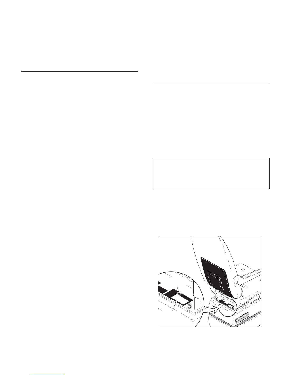
1.4 Parts Replacement Ordering
If a part replacement is required, order the part directly
from the factory as follows:
(1) Refer to Figure 1-2 to determine the location of
the model number and serial number of the chair
and record this data.
(2) Refer to the Parts List to determine the item
numbers of the parts, part numbers of the parts,
descriptions of the parts, and quantities of parts
needed and record this data (Refer to para 6.1).
NOTE
Ask the Purchasing Department of the company that
owns the chair for this information. Otherwise, this
information may be obtained from the dealer that sold
the chair.
(3) Determine the installation date of the chair and
record this data.
(4) Call Midmark with the recorded information and
ask for the Medical Products Technical Services Department. See back cover of this
manual for the phone number or use the Fax
Order Form (See page 7-2 for Fax Order Form).
MODEL
NUMBER
MIDMARK
MODEL
INPUT
RATING
SERIAL NO.
115 VAC 60 HZ
417
12 AMP
BPXXXXX
MIDMARK
MODEL
INPUT
RATING
SERIAL NO.
115 VAC 60 HZ
417
12 AMP
BPXXXXX
SERIAL
NUMBER
Figure 1-2. Model Number / Serial
Number Location
MIDMARK
417
MA2476
© Midmark 1994 SF-1399 Rev. 8/07 Page 1-5 Printed in U.S.A.

SECTION I
GENERAL INFORMATION
1.5 Special Tools
Table 1-2 lists all of the special tools needed to repair
the chair, how to obtain the special tools, and the
purpose of each special tool.
Table 1-2. Special Tool List
Description of Special Tool
Multimeter Commercially Available Any Type Used to perform continuity and voltage checks.
Torque Wrench Commercially Available Any Type Used to tighten hardware to specified torque
Manufacturer's
Name / Address / Phone
Manufacturer's
Part Number
Purpose of Special Tool
values.
© Midmark 1994 SF-1399 Rev. 12/03 Page 1-6 Printed in U.S.A.

TESTING AND TROUBLESHOOTING
!
SECTION II
TESTING AND TROUBLESHOOTING
SECTION II
2.1 Operational Test (See Figure 2-1)
In order to effectively diagnose the malfunction of the
chair, it may be necessary to perform an operational
test as follows:
DANGER
Refer to the Operator Manual for
complete instructions on operating the
chair. Failure to do so could result in personal
injury.
NOTE
The Operational Test, for the most part, only describes what should happen when the chair is
operated. If the chair does something other than
described, a problem has been discovered. Refer to
the Troubleshooting Guide to determine the cause of
the problem and its correction.
(1) Plug the chair into a grounded, non-isolated,
correctly polarized outlet that has the proper
voltage output for the chair.
NOTE
To disable the chair, the control disable switch must
be thrown toward foot end of chair.
(2) Switch the CONTROL DISABLE switch to the
disable position (See Figure 2-1).
(7) Observe. The table top should move in the
direction corresponding to the pedal which is
being depressed. Each function should have
the following range of motion:
TABLE UP to TABLE DOWN - 22.5 in. to
41 in. (57.2 cm to 106.7 cm)
TILT DOWN to TILT UP - 0° to 30°
BACK DOWN to BACK UP - 16° to -83°
Function speeds should be as follows:
TABLE DOWN to TABLE UP - 15 seconds
BACK DOWN to BACK UP - 8 seconds
TILT DOWN to TILT UP - 8 seconds.
When an actuator assembly reaches its limit,
the PC control board should automatically stop
the function from freewheeling after a short
time. The arm rests should be parallel with the
seat section of the table top when the back
section is all the way up.
(8) Place approximately 300 lbs (136 kg) on seat
section of table top. Run TABLE UP and
TABLE DOWN functions all the way up and all
the way down.
(9) Observe. The base actuator assembly should
be able to raise and lower normally with the 300
lb (136 kg) load. The base actuator assemby
should not squeal or make excessive noise
when it freewheels at the end of its stroke.
(3) Depress TABLE UP, TABLE DOWN, BACK
UP, BACK DOWN, TILT UP, and TILT DOWN
pedals on foot control.
(4) Observe. No functions should operate.
NOTE
To enable the chair, the control disable switch must
be thrown toward head end of chair.
(5) Switch the CONTROL DISABLE switch to
enable position.
(6) Depress TABLE UP, TABLE DOWN, BACK
UP, BACK DOWN, TILT UP, and TILT DOWN
pedals on foot control and run each function to
its limit.
© Midmark Corporation 1994 SF-1399 Page 2-1 Printed in U.S.A.
(10) Remove the 300 lb (136 kg) weight.
(11) Raise TABLE UP function all the way up.
(12) Depress the AUTO RETURN foot switch. After
the table top lowers halfway, depress the STOP
foot switch.
(13) Observe. When the AUTO RETURN foot
switch is depressed, the table top should begin
to lower. When the STOP foot switch is
depressed, the table top should stop lowering.
(14) Depress the AUTO RETURN foot switch and
allow the table top to lower completely.
SECTION II
TESTING AND TROUBLESHOOTING
HAND CONTROL
BUTTONS (OPTIONAL)
STOP
AUTO
RETURN
POSITION
"1"
POSITION
"3"
POSITION
FOOT CONTROL
SWITCHES
STOP
AUTO
RETURN
"4"
TILT
UP
AUTO
RETURN
POSITION
POSITION
1
POSITION
POSITION
3
2
POSITION
4
POSITION
"2"
POSITION
POSITION
"1"
BACK
FOOT
UP
STOP
UP
"2"
MIDMARK
TABLE
UP
BACK
UP
BACK
TILT
DOWN
UP
TILT
DOWN
FOOT
DOWN
PROGRAM
TABLE
UP
TABLE
DOWN
PROGRAM
TABLE
DOWN
BACK
DOWN
TILT
DOWN
PARALLEL
FOOT
SECTION
TABLE
TOP
SEAT
SECTION
BACK
SECTION
ARM
REST
CONTROL
DISABLE
SWITCH
TABLE
UP
TABLE
DOWN
BACK
UP
BACK
DOWN
TILT
UP
TILT
DOWN
Figure 2-1. Operational Test
417
MIDMARK
FOOT
CONTROL
CAUTION
D
E
T
A
CONTROL
C
H
FO
O
NOT IN USE
T
W
HEN
MA2474
© Midmark Corporation 1994 SF-1399 Page 2-2 Printed in U.S.A.

SECTION II
TESTING AND TROUBLESHOOTING
(15) Observe. When the table top is completely
lowered, the base actuator assembly should
stop running (before the base actuator assembly is allowed to freewheel), indicating that the
base down limit switch has been tripped.
NOTE
A hand control is an optional accessory; not all units
have one.
(16) If chair has a hand control, repeat steps 6, 7,
and 11 thru 15 using the buttons on the hand
control.
(17) Depress the PROGRAM foot switch on foot
control - one second for new style board and
0.2 seconds for old style board.
NOTE
A program position foot switch must be depressed
within 5 seconds of depressing the PROGRAM foot
switch.
Table 2-1. Troubleshooting Guide
(18) Depress the POSITION "1" foot switch.
(19) Use any of the single function foot pedals to
move the table top to a new position.
(20) Depress the POSITION "1" foot switch.
(21) Observe. The table top should move back to
the position programmed in steps 17 and 18.
NOTE
A hand control is an optional accessory; not all units
have one.
(22) If chair has a hand control, repeat steps 17 thru
21 using the PROGRAM button and POSITION
"1", "2", "3", and "4" buttons on the hand control
instead of foot control.
2.2 Troubleshooting Procedures
Table 2-1 is a Troubleshooting Guide which is used to
determine the cause of the malfunction.
melborPmotpmySesuaCelbaborPkcehCnoitcerroC
etarepotonlliwriahC
puxisehtfoynanehw
,snoitcnufnwoddna
otuaro,noitcnufmargorp
eranoitcnufnruter
.detceles
rohctiwstoofanehW
sinottublortnocdnah
rotautcasti,desserped
.muhronurtonseod
.gninoitcnuflam
.deppirt
deggulptonsidrocrewoP
.teltuollawytilicafotni
nihctiwselbasidlortnoC
.noitisop"FFO"otdenrut
sihctiwselbasidlortnoC
rekaerbtiucricytilicaF
.esoolsnoitcennoceriWgniriwllakcehC
rewopfieesotkcehC
.nideggulpsidroc
enofoedismottobno
owts'riahcehtfo
.)steltuolacirtcele
ytiunitnocamrofreP
lortnocehtnokcehc
.hctiwselbasid
siriahcotrewopgnidivorp
.otni
ytilicaffieesotkcehC
sirekaerbtiucric
foyawenO.deppirt
morfsnoitcennoc
otdrocrewop
ehtno1Jrotcennoc
.draoblortnocCP
ytiunitnocmrofreP
esU.seriwnokcehc
.slevelegatlovreporp
ytilicafotnidrocrewopgulP
rotcennocro/dnateltuollaw
.riahcnoelcatpecer
lortnocfieesotkcehC
ehtnisihctiwselbasid
detacol(noitisop"FFO"
gulpotsisihtgnikcehc
teltuollawotnipmala
deggulpsawriahctaht
rofkcehcotretemitlum
elbasidlortnocehthctiwS
.noitisop"NO"othctiws
elbasidlortnocehtecalpeR
.6.4arapotrefeR.hctiws
,deppirtsirekaerbtiucricfI
desuactahwenimreted
tcerroc,pirtotrekaerbtiucric
nehtdna,melborpeht
.rekaerbtiucricecalper/teser
.snoitcennocytridynanaelC
esoolynanethgiT
ynaecalpeR.snoitcennoc
.snoitcennocdegamad
© Midmark Corporation 1994 SF-1399 Rev. 1/04 Page 2-3 Printed in U.S.A.

SECTION II
TESTING AND TROUBLESHOOTING
Table 2-1. Troubleshooting Guide - Continued
Problem Symptom Probable Cause Check Correction
Chair will not operate
when any of the six up
and down functions,
program function, or
auto return function are
selected - Continued.
No actions can be
initiated from foot
control.
No actions can be
initiated from hand
control.
When a foot switch or hand
control button is
depressed, its actuator
does not run or hum Continued.
Chair has power, but no
functions can be initiated
from foot control (hand
control functions properly).
Chair has power, but no
functions can be initiated
from hand control (foot
control functions properly).
0.5 amp fuse or 20 amp
fuse on old style PC control
board or 0.125 amp fuse on
new style PC control board
is blown.
The supply voltage for PC
control board is below
normal limits.
PC control board is locked
up and needs to be
reinitialized.
PC control board is
malfunctioning.
Hand control, foot control,
or coil cord malfunctioning.
Coil cord is not plugged into
foot control or receptacle on
chair properly.
Coil cord receptacle on
chair is malfunctioning.
Coil cord receptacle (is part
of foot control interface
board) on foot control is
malfunctioning.
Coil cord is malfunctioning. Use a multimeter to perform a
Coil cord is not plugged into
hand control or receptacle
on chair properly.
Ribbon connector from
hand control panel has
become disconnected from
the control interface board.
Coil cord receptacle on
chair is malfunctioning.
Coil cord receptacle (is part
of control interface board)
on hand control is
malfunctioning.
Refer to Figure 2-2 for this
check. Perform continuity
check on fuses.
Check facility power source
for voltage between 110 - 120
VAC.
— Reinitialize the PC control
Replace suspect PC control
board with known working PC
control board. On new style
PC control boards, check if
green Board Fail L.E.D. is
flashing. Flashing indicates
normal operation, while not
flashing indicates a
malfunction.
Replace suspect component
with known working
component.
Check if coil cord is plugged
in properly.
Plug foot control into
receptacle on other side of
chair and then attempt to
operate chair. If works now,
receptacle was
malfunctioning.
Replace suspect foot control
interface board with known
working foot control interface
board.
continuity check on the coil
cord.
Check if coil cord is plugged
in properly.
Check if ribbon connector is
connected to the control
interface board properly.
Plug hand control into
receptacle on other side of
chair and then attempt to
operate chair. If works now,
receptacle was
malfunctioning.
Replace suspect control
interface board with known
working control interface
board.
Replace any blown fuses.
If voltage is below 110
VAC, correct low voltage
problem of facility power
source.
board. Refer to para 4.2.
Replace PC control board.
Refer to para 4.8.
Replace malfunctioning
component.
Plug coil cord into foot
control or receptacle on
chair. Clean any dirty
connections.
Replace receptacle.
Replace foot control
interface board. Refer to
para 4.24.
Replace coil cord.
Plug coil cord into hand
control or receptacle on
chair. Clean any dirty
connections.
Connect ribbon connector
of hand control panel to
control interface board.
Refer to para 4.21.
Replace receptacle.
Replace control interface
board. Refer to para 4.21.
© Midmark Corporation 1994 SF-1399 Rev. 1/97 Page 2-4 Printed in U.S.A.
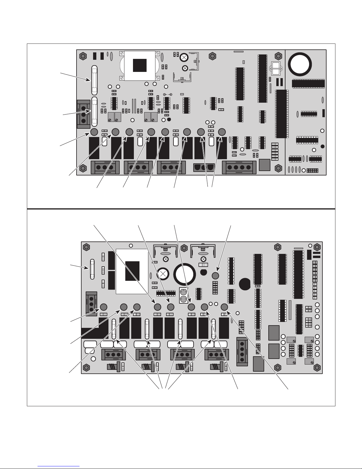
OLD
STYLE
0.5 amp.
FUSE
20 amp.
FUSE
TABLE
UP
L.E.D.
TABLE
DOWN
L.E.D.
BACK
UP
L.E.D.
BACK
DOWN
L.E.D.
TILT
UP
L.E.D.
TILT
DOWN
L.E.D.
SECTION II
TESTING AND TROUBLESHOOTING
L.E.D.'S NOT
USED ON
417 MODEL
NEW
STYLE
0.125 amp.
FUSE
TABLE
UP
L.E.D.
TABLE
DOWN
L.E.D.
BACK
UP
L.E.D.
BACK
DOWN
L.E.D.
TILT
UP
L.E.D.
DOWN
L.E.D.
5 amp.
FUSES
TILT
BOARD
FAIL
L.E.D.
L.E.D. NOT
USED ON
417 MODEL
L.E.D. NOT
USED ON
417 MODEL
MA2475
Figure 2-2. Indicator L.E.D.'s For Use With Troubleshooting Guide
© Midmark Corporation 1994 SF-1399 Page 2-5 Printed in U.S.A.

SECTION II
TESTING AND TROUBLESHOOTING
Table 2-1. Troubleshooting Guide - Continued
Problem Symptom Probable Cause Check Correction
No actions can be
initiated from hand
control - Continued.
Chair has power, but no
functions can be initiated
from hand control (foot
control functions properly)
- Continued.
Coil cord is malfunctioning. Use a multimeter to perform a
continuity check on the coil
cord.
Hand control is malfunctioning. Replace suspect control
interface board with known
working control interface board.
Replace coil cord.
Replace control interface board.
Refer to para 4.21.
One or more functions
cannot be initiated from
foot control or hand
control.
TABLE UP and
TABLE DOWN
functions do not work.
Some functions may be
initiated with foot control or
hand control, but some
may not.
When TABLE UP and
TABLE DOWN buttons
are pressed, the chair will
not move (all other
functions work).
Replace suspect hand control
panel with known working hand
control panel.
Reinitialization routine was not
fully completed.
Hand control panel of hand
control is malfunctioning
(switch membrane is
malfunctioning).
A push-button switch in foot
control is malfunctioning.
Wire connections loose in foot
control.
Base capacitor is weak or
blown.
Thermal overload switch in
base actuator assembly is
activated.
Base actuator assembly is
malfunctioning.
5 amp fuse for TABLE UP and
TABLE DOWN functions is
blown (applies to new style PC
board only).
Wire connections loose. Check all wiring connections to
Gas spring(s) are
malfunctioning.
Base actuator is drawing
excessive current for more than
0.5 seconds.
Replace suspect hand control
panel with known working hand
control panel.
Perform continuity check on
push-button switch or replace
push-button switch with a
known working switch.
Check all wiring connections
from the push-button switch to
the control interface board.
Replace suspect base capacitor
with known working base
capacitor.
Replace suspect base actuator
assembly or actuator motor with
a known working assembly.
Refer to Figure 2-2 for this
check. Perform continuity check
on fuse.
base actuator assembly.
Replace suspect gas spring(s)
with known working gas
spring(s).
Release all buttons. Then, run
base actuator again to see if it
stops running again.
— Run another reinitialization
— Wait 10 to 20 minutes to allow
Replace hand control panel.
Refer to para 4.21.
procedure. If it doesn't work,
unplug all actuator wire
harnesses from PC board and
run a third initialization
procedure. Refer to para 4.2.
Replace hand control panel.
Refer to para 4.21.
Replace push-button switch.
Refer to para 4.22 or 4.23.
Clean any dirty connections.
Tighten any loose connections.
Replace any damaged
connections.
Replace base capacitor. Refer
to para 4.14.
base actuator assembly to cool.
Replace actuator motor or base
actuator assembly. Refer to
para 4.11 or 4.12.
Replace blown fuse.
Clean any dirty connections.
Tighten any loose connections.
Replace any damaged
connections.
Replace gas spring(s). Refer to
para 4.13.
If problem repeats, replace
base capacitor, actuator motor,
or actuator. Refer to para 4.14,
4.11, or 4.12.
© Midmark Corporation 1994 SF-1399 Rev. 10/99 Page 2-6 Printed in U.S.A.

TESTING AND TROUBLESHOOTING
Table 2-1. Troubleshooting Guide - Continued
Problem Symptom Probable Cause Check Correction
TABLE UP and
TABLE DOWN
functions do not work Continued.
BACK UP and BACK
DOWN functions do
not work.
TILT UP and TILT
DOWN functions do
not work.
When TABLE UP and
TABLE DOWN buttons are
pressed, the chair will not
move (all other functions
work) - Continued.
When BACK UP and BACK
DOWN buttons are pressed,
the chair will not move (all
other functions work).
When TILT UP and TILT
DOWN buttons are pressed,
the chair will not move (all
other functions work).
PC control board is
malfunctioning.
Back capacitor is weak or
blown.
Thermal overload switch in
back actuator assembly is
activated.
Back actuator assembly is
malfunctioning.
5 amp fuse for BACK UP
and BACK DOWN functions is blown (applies to
new style PC board only).
Wire connections loose. Check all wiring connections
Back actuator is drawing
excessive current for more
than 0.5 seconds.
PC control board is
malfunctioning.
Tilt capacitor is weak or
blown.
Thermal overload switch in
tilt actuator assembly is
activated.
Tilt actuator assembly is
malfunctioning.
Refer to Figure 2-2 for this
check. Press TABLE UP and
then the TABLE DOWN
button while observing the PC
control board. The TABLE
UP L.E.D. should illuminate
when the TABLE UP button is
pressed and TABLE DOWN
L.E.D. should illuminate when
the TABLE DOWN button is
pressed. If not, PC control
board is malfunctioning.
Replace suspect back
capacitor with known working
back capacitor.
— Wait 10 to 20 minutes to
Replace suspect back
actuator assembly or actuator
motor with a known working
assembly.
Refer to Figure 2-2 for this
check. Perform continuity
check on fuse.
to back actuator assembly.
Release all buttons. Then,
run back actuator again to
see if it stops running again.
Refer to Figure 2-2 for this
check. Press BACK UP and
then the BACK DOWN button
while observing the PC
control board. The BACK UP
L.E.D. should illuminate when
the BACK UP button is
pressed and the BACK
DOWN L.E.D. should
illuminate when the BACK
DOWN button is pressed. If
not, PC control board is
malfunctioning.
Replace suspect tilt capacitor
with known working tilt
capacitor.
— Wait 10 to 20 minutes to
Replace suspect tilt actuator
assembly or actuator motor
with a known working assy.
Replace PC control board.
Refer to para 4.8.
Replace back capacitor.
Refer to para 4.18.
allow back actuator
assembly to cool.
Replace actuator motor or
back actuator assembly.
Refer to para 4.11 or 4.17.
Replace blown fuse.
Clean any dirty connections. Tighten any loose
connections. Replace any
damaged connections.
If problem repeats, replace
back capacitor, actuator
motor, or actuator. Refer to
para 4.18, 4.11, or 4.17.
Replace PC control board.
Refer to para 4.8.
Replace tilt capacitor.
Refer to para 4.16.
allow tilt actuator assembly
to cool.
Replace actuator motor or
tilt actuator assembly.
Refer to para 4.11 or 4.15.
SECTION II
© Midmark Corporation 1994 SF-1399 Rev. 1/97 Page 2-7 Printed in U.S.A.

SECTION II
TESTING AND TROUBLESHOOTING
Table 2-1. Troubleshooting Guide - Continued
Problem Symptom Probable Cause Check Correction
TILT UP and TILT
DOWN functions do not
work - Continued.
TABLE UP function
works, but TABLE
DOWN function does
not or TABLE DOWN
function works, but
TABLE UP function
does not. All other
functions work.
When TILT UP and TILT
DOWN buttons are pressed,
the chair will not move (all
other functions work) Continued.
One function runs properly,
but the other does not.
5 amp fuse for TILT UP and
TILT DOWN functions is
blown (applies to new style
PC board only).
Wire connections loose. Check all wiring connections
Tilt actuator is drawing
excessive current for more
than 0.5 seconds.
PC control board is
malfunctioning.
Wire connections loose. Check all wiring connections
Gas spring(s) are
malfunctioning (especially
for TABLE UP function).
PC control board is
malfunctioning.
TABLE UP or TABLE
DOWN foot switch is
malfunctioning.
Hand control panel of hand
control is malfunctioning
(switch membrane is
malfunctioning).
Refer to Figure 2-2 for this
check. Perform continuity
check on fuse.
to tilt actuator assembly.
Release all buttons. Then,
run tilt actuator again to see
if it stops running again.
Refer to Figure 2-2 for this
check. Press TILT UP and
then the TILT DOWN button
while observing PC control
board. The TILT UP L.E.D.
should illuminate when TILT
UP button is pressed and
TILT DOWN L.E.D. should
illuminate when the TILT
DOWN button is pressed. If
not, the PC control board is
malfunctioning.
to base actuator assembly.
Replace suspect gas
spring(s) with known
working gas spring(s).
Refer to Figure 2-2 for this
check. Press TABLE UP
and then the TABLE DOWN
button while observing the
PC control board. The
TABLE UP L.E.D. should
illuminate when the TABLE
UP button is pressed and
the TABLE DOWN L.E.D.
should illuminate when the
TABLE DOWN button is
pressed. If not, PC control
board is malfunctioning.
Perform a continuity check
on suspect foot switch.
Replace suspect hand
control panel with known
working hand control panel.
Replace blown fuse.
Clean any dirty
connections. Tighten any
loose connections.
Replace any damaged
connections.
If problem repeats, replace
tilt capacitor, actuator
motor, or actuator. Refer to
para 4.16, 4.11, or 4.15.
Replace PC control board.
Refer to para 4.8.
Clean any dirty
connections. Tighten any
loose connections.
Replace any damaged
connections.
Replace gas spring(s).
Refer to para 4.13.
Replace PC control board.
Refer to para 4.8.
Replace foot switch. Refer
to para 4.22.
Replace hand control panel.
Refer to para 4.21.
© Midmark Corporation 1994 SF-1399 Rev. 1/97 Page 2-8 Printed in U.S.A.

TESTING AND TROUBLESHOOTING
Table 2-1. Troubleshooting Guide - Continued
melborPmotpmySesuaCelbaborPkcehCnoitcerroC
noitcnufPUELBAT
tub,ylreporpskrow
noitcnufNWODELBAT
.tonseod
noitcnufNWODELBAT
tub,ylreporpskrow
noitcnufPUELBAT
.tonseod
muhtonseodrotomrotautcA
.detcelessinoitcnufnehw
muhtonseodrotomrotautcA
.detcelessinoitcnufnehw
sihctiwstimilnwodesaB
.nepokcuts-gninoitcnuflam
sihctiwstimilpuesaB
.nepokcuts-gninoitcnuflam
.deppirtton
.hctiwstimilnwodesab
nehwytiunitnocebdluohS
.deppirttonsihctiws
SECTION II
nokcehcytiunitnocmrofreP
nokcehcytiunitnocmrofreP
dluohS.hctiwstimilpuesab
sihctiwsnehwytiunitnoceb
timilnwodesabecalpeR
.01.4arapotrefeR.hctiws
timilpuesabecalpeR
.82.4arapotrefeR.hctiws
skrowNWODELBAT
PUELBATtub,ylreporp
roesiartonlliwnoitcnuf
rofenifsevom(ylwolssesiar
evomtonlliwtub,tneitapthgil
.)tneitapyvaeh
noitcnufPUKCAB
KCABtub,skrow
seodnoitcnufNWOD
NWODKCABroton
tub,skrownoitcnuf
noitcnufPUKCAB
rehtollA.tonseod
.krowsnoitcnuf
noitcnufPUTLIT
NWODTLITtub,skrow
rotonseodnoitcnuf
noitcnufNWODTLIT
PUTLITtub,skrow
llA.tonseodnoitcnuf
.krowsnoitcnufrehto
yrevrofylwolssevomro
,ylreporpsnurnoitcnufenO
.tonseodrehtoehttub
,ylreporpsnurnoitcnufenO
.tonseodrehtoehttub
era)s(gnirpssaG
.gninoitcnuflam
.esoolsnoitcennoceriWsnoitcennocgniriwllakcehC
timiLpUronwoDkcaB
desolCyllamroN,hctiwS
eriwronepoera,stcatnoc
.detcennocsid
sidraoblortnocCP
.gninoitcnuflam
NWODKCABroPUKCAB
sihctiwstoof
.gninoitcnuflam
dnahfolenaplortnocdnaH
gninoitcnuflamsilortnoc
sienarbmemhctiws(
.)gninoitcnuflam
.esoolsnoitcennoceriWsnoitcennocgniriwllakcehC
hctiwStimiLpUronwoDtliT
stcatnocdesolCyllamroN
eriwronepoera
.detcennocsid
sagtcepsusecalpeR
nwonkhtiw)s(gnirps
.)s(gnirpssaggnikrow
.ylbmessarotautcaesabot
kcaBfonoitidnockcehC
hctiwStimiLpUronwoD
.snoitcennocdnastcatnoc
sihtrof2-2erugiFotrefeR
dnaPUKCABsserP.kcehc
NWODKCABehtneht
ehtgnivresboelihwnottub
ehT.draoblortnocCP
dluohs.D.E.LPUKCAB
KCABehtnehwetanimulli
dnadesserpsinottubPU
.D.E.LNWODKCABeht
ehtnehwetanimullidluohs
sinottubNWODKCAB
lortnocCP,tonfI.desserp
.gninoitcnuflamsidraob
kcehcytiunitnocamrofreP
.hctiwstooftcepsusno
dnahtcepsusecalpeR
nwonkhtiwlenaplortnoc
.lenaplortnocdnahgnikrow
.ylbmessarotautcaesabot
nwoDtliTfonoitidnockcehC
stcatnochctiwStimiLpUro
.snoitcennocdna
.22.4arapot
.)s(gnirpssagecalpeR
.31.4arapotrefeR
.snoitcennocytridynanaelC
esoolynanethgiT
ynaecalpeR.snoitcennoc
.snoitcennocdegamad
kcaBecalperroriapeR
.hctiwStimiLpUronwoD
.4arapotrefeR
.draoblortnocCPecalpeR
.8.4arapotrefeR
refeR.hctiwstoofecalpeR
.lenaplortnocdnahecalpeR
.12.4arapotrefeR
.snoitcennocytridynanaelC
esoolynanethgiT
ynaecalpeR.snoitcennoc
.snoitcennocdegamad
nwoDtliTecalperroriapeR
.hctiwStimiLpUro
.4arapotrefeR
© Midmark Corporation 1994 SF-1399 Rev. 12/03 Page 2-9 Printed in U.S.A.

SECTION II
TESTING AND TROUBLESHOOTING
Table 2-1. Troubleshooting Guide - Continued
melborPmotpmySesuaCelbaborPkcehCnoitcerroC
noitcnufPUTLIT
TLITtub,skrow
,tonseodNWOD
NWODTLITro
TLITtubskrow
.tonseodPU
.deunitnoC
NRUTEROTUA
tonseodnoitcnuf
.ylreporpetarepo
.desserped
ylreporpsnurnoitcnufenO
.tonseodrehtoehttub
ehtnehwsneppahgnihtoN
sinottubNRUTEROTUA
.deppirt
sidraoblortnocCP
.gninoitcnuflam
sidraoblortnocCP
.gninoitcnuflam
sdeendraoblortnocCP
.dezilaitinier
sihctiwstimilnwodesaB
.kcehc
.draoblortnoc
.gninoitcnuflam
—
sihtrof2-2erugiFotrefeR
nehtdnaPUTLITsserP
nottubNWODTLITeht
CPehtgnivresboelihw
dluohs.D.E.LPUTLITehT
siPUTLITnehwetanimulli
TLITdnadesserped
dluohs.D.E.LNWOD
TLITnehwetanimulli
.desserpedsiNWOD
sidraoblortnocCP,tonfI
CPtcepsusecalpeR
nwonkhtiwdraoblortnoc
.draoblortnocCPgnikrow
derewolydaerlasiriahC
gnippirt,nwodyawehtlla
nwodesabrohctiwstimil
fotuosihctiwstimil
esabgnisuac,tnemtsujda
othctiwstimilnwod
pirtotrodeppirtniamer
.derisednahtreilrae
.hctiws
.8.4arapotrefeR
.8.4arapotrefeR
.draoblortnocCPecalpeR
.draoblortnocCPecalpeR
lortnocCPehtezilaitinieR
.2.4arapotrefeR.draob
timilnwodesabtsujdA
.01.4arapotrefeR
sihctiwstimilnwodesaB
.nepokcuts-gninoitcnuflam
.)deppirtton
.gninoitcnuflamsi
.)gninoitcnuflam
NRUTEROTUAnehW
ELBAT,desserpsinottub
tonseodnoitcnufNWOD
tinehwyllacitamotuapots
.tnioptsewolstisehcaer
.dezilaitinier
.)hctiwstimil
hctiwstoofNRUTEROTUA
dnahfolenaplortnocdnaH
gninoitcnuflamsilortnoc
sienarbmemhctiws(
sdeendraoblortnocCP
sihctiwstimilnwodesaB
otylppatonseod(deppirt
tonodhcihwsriahcredlo
.)hctiwstimilaevah
sihctiwstimilnwodesaB
nepokcuts-gninoitcnuflam
redlootylppatonseod(
aevahtonodhcihwsriahc
.lenap
—
.)deppirtton
kcehcytiunitnocmrofreP
chtiwstimilnwodesabno
nehw.O.Nsihctiwstimil(
kcehcytiunitnocamrofreP
.hctiwstooftcepsusno
dnahtcepsusecalpeR
nwonkhtiwlenaplortnoc
lortnocdnahgnikrow
derewolydaerlasiriahC
gnippirt,nwodyawehtlla
nwodesabrohctiwstimil
fotuosihctiwstimil
esabgnisuac,tnemtsujda
othctiwstimilnwod
pirtotrodeppirtniamer
.derisednahtreilrae
kcehcytiunitnocmrofreP
chtiwstimilnwodesabno
nehw.O.Nsihctiwstimil(
.32.4arapot
.hctiws
timilnwodesabecalpeR
.01.4arapotrefeR.hctiws
refeR.hctiwstoofecalpeR
lortnocdnahecalpeR
.12.4arapotrefeR.lenap
lortnocCPehtezilaitinieR
.2.4arapotrefeR.draob
timilnwodesabtsujdA
.01.4arapotrefeR
timilnwodesabecalpeR
.01.4arapotrefeR.hctiws
© Midmark Corporation 1994 SF-1399 Rev. 12/03 Page 2-10 Printed in U.S.A.

TESTING AND TROUBLESHOOTING
Table 2-1. Troubleshooting Guide - Continued
melborPmotpmySesuaCelbaborPkcehCnoitcerroC
SECTION II
s'riahcehT
.ylreporp
noitcnufMARGORP
krowtonseod
.noitisop
/draobmargorpCPehT
tonseoddraoblortnocCP
demmargorpadloh
.)ylno
neebsahriahC
.syad
.dezilaitinier
silortnocdnah
sienarbmem
rofnekatspetstcerrocnI
.noitisopfoyrtne
tonsidraobmargorpCP
CPotnidetaesylluf
stinuno(draoblortnoc
sdraobelytsdlohtiw
tuohtiwrodeggulpnu
eerhtnahteromrofrewop
sdeendraoblortnocCP
ronottubMARGORP
toof"2"ro"1"NOITISOP
.gninoitcnuflamsihctiws
folenaplortnocdnaH
hctiws(gninoitcnuflam
.)gninoitcnuflam
.erudecorp
—
—
.lenap
s'rotarepoehtotrefeR
reporproflaunam
.erudecorp
CPfieesotkcehC
.esoolsidraobmargorp
kcehcytiunitnocamrofreP
.hctiwstooftcepsusno
dnahtcepsusecalpeR
nwonkhtiwlenaplortnoc
lortnocdnahgnikrow
s'rotarepoehtotrefeR
reporproflaunam
draobmargorpCPtaeS
.draoblortnocCPotniylluf
.8.4arapotrefeR
lortnocCPehtezilaitinieR
.2.4arapotrefeR.draob
lortnocCPehtezilaitinieR
.2.4arapotrefeR.draob
.hctiwstoofecalpeR
.32.4arapotrefeR
lortnocdnahecalpeR
.12.4arapotrefeR.lenap
CP/draobmargorpCP
sidraoblortnoc
.gninoitcnuflam
stiotevomtonseodriahC
demmargorptcerroc
NOITISOPnehwnoitisop
sinottub"4"ro,"3","2","1"
.desserp
neebsahriahC
.syad
.dezilaitinier
silortnocdnah
sienarbmem
.)gninoitcnuflam
sidraoblortnoc
.gninoitcnuflam
tonsidraobmargorpCP
CPotnidetaesylluf
otseilppa(draoblortnoc
CPelytsdlohtiwstinu
.)ylnodraoblortnoc
tuohtiwrodeggulpnu
eerhtnahteromrofrewop
sdeendraoblortnocCP
ronottubMARGORP
toof"2"ro"1"NOITISOP
.gninoitcnuflamsihctiws
folenaplortnocdnaH
hctiws(gninoitcnuflam
CP/draobmargorpCP
—
CPfieesotkcehC
.esoolsidraobmargorp
.draob
—
—
kcehcytiunitnocamrofreP
.hctiwstooftcepsusno
dnahtcepsusecalpeR
nwonkhtiwlenaplortnoc
lortnocdnahgnikrow
.lenap
—
margorpCPecalpeR
.draoblortnocCP/draob
.8.4arapotrefeR
draobmargorpCPtaeS
lortnocCPotniylluf
lortnocCPehtezilaitinieR
.2.4arapotrefeR.draob
lortnocCPehtezilaitinieR
.2.4arapotrefeR.draob
.hctiwstoofecalpeR
.32.4arapotrefeR
lortnocdnahecalpeR
.12.4arapotrefeR.lenap
margorpCPecalpeR
.draoblortnocCP/draob
.8.4arapotrefeR
© Midmark Corporation 1994 SF-1399 Rev. 12/03 Page 2-11 Printed in U.S.A.

SECTION II
TESTING AND TROUBLESHOOTING
Table 2-1. Troubleshooting Guide - Continued
melborPmotpmySesuaCelbaborPkcehCnoitcerroC
s'riahcehT
noitcnufMARGORP
krowtonseod
.deunitnoC-ylreporp
.spots
rofenifsevomriahC
lliwtub,tneitapthgil
sevomroevomton
yvaehyrevrofylwols
.tneitap
stiotevomtonlliwriahC
noitisopdemmargorp
demmargorpehtsselnu
dlehsinottubNOITISOP
fi;evomeritneehtrofnwod
desaelersinottubeht
riahceht,evomgnirud
dnapuehthtobrofsruccO
.snoitcnufnwodeht
.kaew
lortnocCPelytsdlonO
hctiwsrotceles,sdraob
CPehtnodetacol,1S
dellupsi,draoblortnoc
nisihctiws1SnehW(tuo
eht,noitisoptuodellup
NOITISOPdemmargorp
desserpebtsumhctiws
elytswennO.)dlehdna
,sdraoblortnocCP
,4-2WShctiwsrotceles
lortnocCPehtnodetacol
noitisopFFOnisi,draob
FFOnisihctiwsnehW(
demmargorpeht,noitisop
ebtsumhctiwsNOITISOP
.)dlehdnadesserp
gniebsiegatlovwoL
.riahcotdeilppus
oothtiwdedaolrevoriahC
.tneitapafoyvaeh
.thgiew
sinoitcnufrofroticapaC
.noitisopFFOni
.CAV5±CAV
.roticapac
dlono,1ShctiwSfikcehC
si,draoblortnocCPelyts
fironoitisoptuodellupni
wenno4-2WShctiws
sidraoblortnocCPelyts
llawtaegatlovkcehC
511ebdluohS.elcatpecer
yticapacthgiewmumixaM
kcehC.sbl053siriahcrof
sihtdedeecxetneitapfi
roticapactcepsusecalpeR
gnikrownwonkhtiw
wollalliwsiht(
.elcatpecer
ehtlla1ShctiwshsuP
hctiwsevomroniyaw
noitisopNOot4-2WS
NOITISOPdemmargorp
dnadesserpebotnottub
fodaetsnidesaeler
.)dlehdnadesserp
egatlovwoltcerroC
llawtanoitautis
forotareporiahcmrofnI
.riahcfonoitatimilthgiew
ehtrofroticapacecalpeR
otrefeR.noitcnufkaew
.81.4ro,61.4,41.4arap
lliwnoitcnufriahcA
.emit
.nur
trohsarofnurylno
eerhtehtfoynA
ybtfirdsnoitcnuf
.sevlesmeht
gnikaeuqsrognilrihW
nehwdraehsiesion
gniebsirotautcana
.gninnur
.esiwrehto
.rotautcaysioNllabnorettamngieroF
,emitnurdnoces2/1aretfA
spotsnoitcnufdetceleseht
.draob
.gnittestloV
ylreporpsnoitcnufriahC
.noitcnuf
.tnacirbul
gniebsiwardtnerrucrevO
lortnocCPybdetceted
rotcelesV022/V011ehT
lortnocCPehtnohctiws
022ehtottessidraob
siekarbrotautcarotoM
tahtrofgninoitcnuflam
fokcaldnasdaerhtwercs
— rorotomrotautcaecalpeR
/V011ehtfieesotkcehC
nohctiwsrotcelesV022
tessidraoblortnocCPeht
.gnittestloV022ehtot
rotautcatcepsusecalpeR
rotomehtniekarb
nwonkhtiwrotautca
.ekarbrotautcagnikrow
rettamngierofrofkcehC
.sdaerhtwercsllabno
tnacirbulfokcalrofkcehC
.sdaerhtwercsllabno
.roticapac
V022/V011ehthctiwS
CPehtnohctiwsrotceles
011ehtotdraoblortnoc
.gnittestloV
.ekarbrotautcaecalpeR
.11.4arapotrefeR
fforettamngierofllanaelC
.sdaerhtwercsllabfo
sdaerhtwercsllabtaoC
roliotnemtaertPTShtiw
.tnelaviuqe
© Midmark Corporation 1994 SF-1399 Rev. 12/03 Page 2-12 Printed in U.S.A.

SCHEDULED MAINTENANCE
SECTION III
SCHEDULED MAINTENANCE
SECTION III
3.1 Scheduled Maintenance
periodically on the chair. These inspections and
services should be performed as often as indicated in
Table 3-1 is a Scheduled Maintenance Chart which lists
the chart.
the inspections and services that should be performed
Table 3-1. Scheduled Maintenance Chart
Interval Inspection or Service What to Do
Semi-annually Obvious damage Visually check condition of chair for obvious damage such as: cracks in components, missing
Fasteners/hardw are Check chair for missing or loose fasteners/hardware. Replace any missing hardware and
Warning and instructional
decals
Pivot points/moving
parts/accessories
Foot control Check that foot control works correctly. Make sure all foot switches operate properly.
Hand Control (optional) Check that hand control works correctly. Make sure all switch membranes work correctly.
PROGRAM function Check the PROGRAM function works properly. Check that programmed positions can be stored
AUTO RETURN function Check that the AUTO RETURN function works correctly. Make sure the base actuator
Ball screws of actuator
assemblies
Actuator assemblies Operate each function and listen for squealing noises, indicating a bad actuator assembly.
Drift in chair Check each actuator assembly to see if it drifts. Replace actuator assembly brake if
Control disable switch Check operation of control disable switch. Replace switch if necessary. Refer to para 4.6.
Arm Rests Check that arm rests are parallel to the seat section of chair when the back section is all the
Foot section Check operation of foot section and foot section brake lever. Make sure brake lever holds foot
Base Subassembly Check the base subassembly for excessive play. The base of the chair should not be able to
Electrical receptacles Check that the electrical receptacles are functioning properly. Replace electrical receptacles
Upholstery Check all upholstery for rips, tears, or excessive wear. Replace cushions as necessary.
Accessories Check that all accessories have all of their components and that they function properly. If
Reinitialization Reinitialize the PC control board. Refer to para 4.2.
Operational Test Perform an Operational Test to determine if the chair is operating within its specifications (Refer
components, dents in components, or any other visible damage which would cause chair to be
unsafe to operate or would compromise its performance. Repair chair as necessary.
tighten any loose hardware as necessary.
Check for missing or illegible decals. Replace decals as necessary.
Lubricate all exposed pivot points, moving parts, and accessories with silicone based lubricant.
and used.
assembly does not freewheel when it is lowered all the way; it should be stopped by the base
down limit switch. The base actuator should be within 1/4 in (6.35 mm) of freewheeling when
base down limit switch is tripped. If necessary, adjust base down limit switch. Refer to para
4.10.
Extend each actuator assembly and wipe ball screw threads down with a rag to remove foreign
matter. Coat as much of the ball screw threads as possible with STP treatment oil or
equivalent. Run each actuator assembly to both ends of its travel a couple of times to spread
the oil evenly over all of the ball screw threads and then remove excess oil.
Coat ball screw of noisy actuator assembly with STP treatment oil or equivalent. If oil does not
correct the problem, replace the noisy actuator. Refer to para 4.12, 4.15, and 4.17.
necessary. Refer to para 4.11.
way up. If not adjust arm rests. Refer to para 4.19.
section securely in place when released. Adjust if necessary. Refer to para 4.20.
be moved back and forth.
as necessary.
necessary, repair or replace the accessory.
p
p
p
© Midmark 1994 SF-1399 Page 3-1 Printed in U.S.A.
MAINTENANCE / SERVICE
SECTION IV
MAINTENANCE / SERVICE INSTRUCTIONS
SECTION IV
4.1 Introduction
DANGER
Refer to the Operator Manual for
complete instructions on operating the
chair. Failure to do so could result in personal
injury.
NOTE
Perform an operational test on the chair after the
repair is completed to confirm the repair was properly
made and that
The following paragraphs contain removal, installation, repair, and adjustment procedures for the chair.
all
malfunctions were repaired.
4.2 Reinitialization Procedure
A. Reinitialization Procedure #1 (Applies To Chair With
An Old Style Foot Control)
NOTE
The PROGRAM footswitch must be depressed first,
or the chair will begin to move.
AUTO RETURN
FOOT SWITCH
PROGRAM
FOOT SWITCH
TABLE DOWN
FOOT SWITCH
TABLE UP
FOOT SWITCH
Figure 4-1. Reinitialization Procedure #1
(4) If first reinitialization procedure fails, unplug all
actuator wire harnesses from PC board and run
another reinitialization procedure. Then,
reconnect wire harnesses.
B. Reinitialization Procedure #2 (Applies To Chair With
An New Style Foot Control or a Hand Control)
MA2477
(1) Simultaneously depress and hold the PRO-
GRAM, TABLE UP, and TABLE DOWN
footswitches for at least two seconds; then
release footswitches. See Figure 4-1.
CAUTION
When the following step is performed, the
chair will move all of its functions. Make
sure chair is clear of all obstructions. Failure to do so
could result in damage to chair or surrounding items.
(2) Depress and release the AUTO RETURN
footswitch.
(3) Observe. Each actuator assembly will run for
approximately 18 seconds to ensure that it
reaches its mechanical home position (if the run
time is less than 18 seconds, the procedure
probably did not work and should be attempted
again). The mechanical home position is:
BACK UP function all the way up, TABLE
DOWN function all the way down, and TILT
DOWN function all the way down. When
actuator assemblies stop running, the
reinitialization procedure is complete.
NOTE
The PROGRAM switch must be depressed first, or
the chair will begin to move.
(1) Simultaneously depress and hold the PRO-
GRAM, POSITION "1", and POSITION "2"
switches for at least two seconds; then release
switches. See Figure 4-2.
CAUTION
When the following step is performed, the
chair will move all of its functions. Make
sure chair is clear of all obstructions. Failure to do so
could result in damage to chair or surrounding items.
(2) Depress and release the AUTO RETURN
switch.
(3) Observe. Each actuator assembly will run for
approximately 18 seconds to ensure that it
reaches its mechanical home position (if the run
time is less than 18 seconds, the procedure
probably did not work and should be attempted
again). The mechanical home position is:
© Midmark 1994 SF-1399 Page 4-1 Printed in U.S.A.
SECTION IV
MAINTENANCE / SERVICE
HAND CONTROL (OPTIONAL)
AUTO
POSITION
"1"
SWITCH
RETURN
SWITCH
RETURN
POSITION
1
POSITION
3
POSITION
4
POSITION
POSITION
2
FOOT
UP
STOP
AUTO
POSITION
PROGRAM
"2"
SWITCH
NEW STYLE
FOOT CONTROL
AUTO
RETURN
SWITCH
POSITION
"1"
SWITCH
POSITION
"2"
SWITCH
Figure 4-2. Reinitialization Procedure #2
BACK UP function all the way up, TABLE
DOWN function all the way down, and TILT
DOWN function all the way down. When
actuator assemblies stop running, the
reinitialization procedure is complete.
TABLE
UP
BACK
UP
TILT
DOWN
UP
TILT
DOWN
FOOT
DOWN
SWITCH
PROGRAM
MIDMARK
TABLE
DOWN
BACK
SWITCH
MA2478
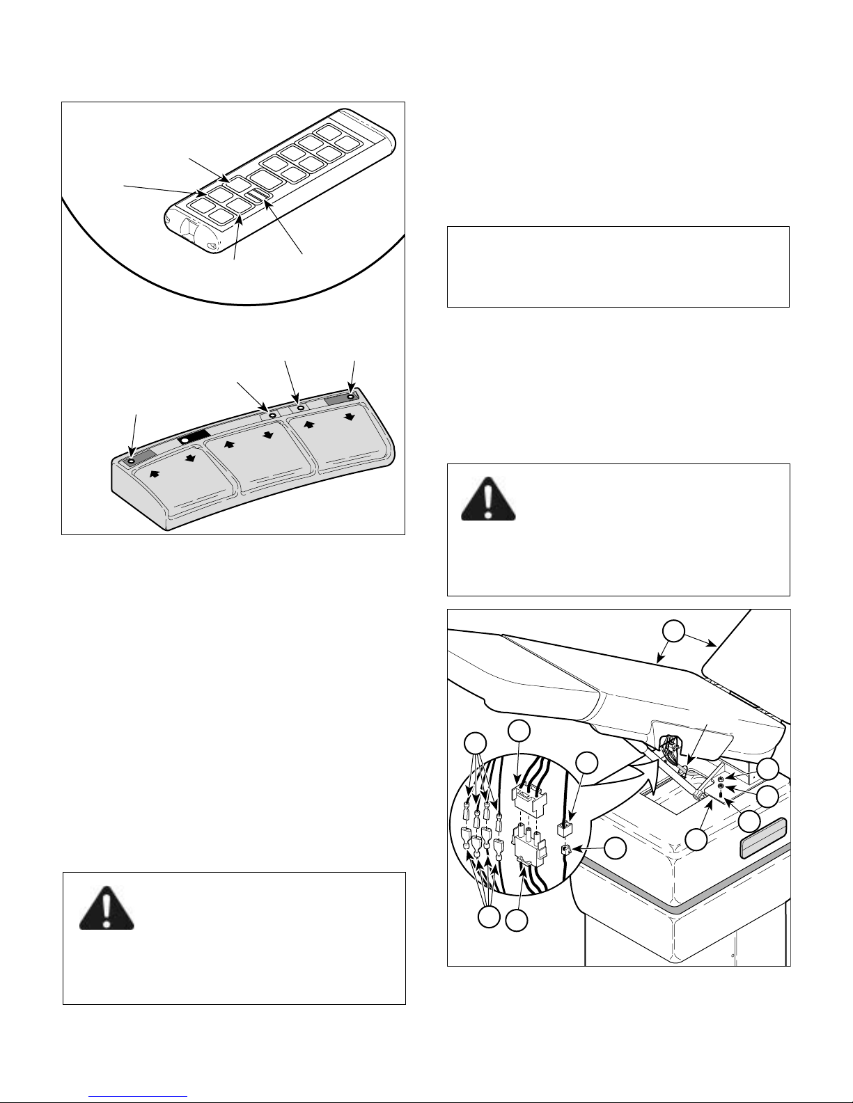
(2) Unplug power cord from wall outlet.
(3) Unplug power cord wire harness (1, Figure 4-3)
from wire harness (2).
(4) Disconnect cord set (3) from modular
coupler (4).
NOTE
Units with Serial Numbers BP-1000 thru BP-1363
have only three wires to disconnect. This is because
these units do not have a base down limit switch.
(5) Tag and disconnect four wires (5) from four
wires (6).
(6) Cut cable tie which is securing wires/wire
harness to table top.
(7) Remove four nuts (7) and lockwashers (8) from
studs (9).
DANGER
Table top weighs approximately 140
lbs (63.5 kg) (without upholstery). Use
an assistant to help in removing table top. Use
proper lifting techniques to prevent back strain.
Failure to do so could result in serious personal
injury.
10
(4) If first reinitialization procedure fails, unplug all
actuator wire harnesses from PC board and run
another reinitialization procedure. Then,
reconnect wire harnesses.
4.3 Table Top Removal / Installation
A. Removal
6
2
4
CABLE
TIE
7
8
9
(1) Raise BACK UP and TILT UP functions all the
way up.
3
11
MIDMARK
417
DANGER
Always unplug the power cord from
the wall outlet before removing any of
the chair's shrouds/covers or making any repairs
to prevent the possibility of electrical shock.
Failure to comply with these instructions could
result in severe personal injury or death.
© Midmark 1994 SF-1399 Rev. 10/99 Page 4-2 Printed in U.S.A.
5
1
MA2479
Figure 4-3. Table Top Removal / Installation
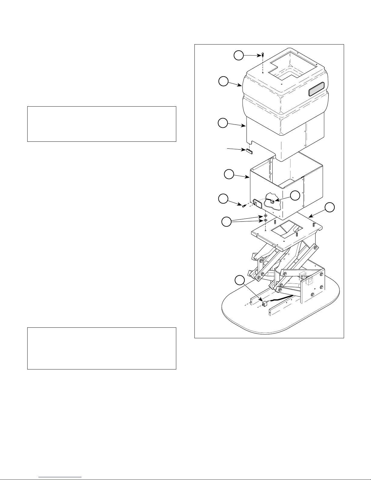
(8) With the help of an assistant, remove table top
(10) from plate (11).
B. Installation
SECTION IV
MAINTENANCE / SERVICE
1
(1) With the help of an assistant, install table top
(10) on plate (11) and secure with four
lockwashers (8) and nuts (7).
NOTE
Units with Serial Numbers BP-1000 thru BP-1363
have only three wires to disconnect. This is because
these units do not have a base down limit switch.
(2) Connect four wires (5) to four wires (6).
(3) Connect cord set (3) to modular coupler (4).
(4) Connect power cord wire harness (1) to wire
harness (2).
(5) Secure wires/wire harness to table top with
cable tie.
(6) Plug power cord into wall receptacle.
4.4 Shrouds Removal / Installation
A. Removal
2
3
PROTECTIVE
TRIM
9
8
5
FOOT
CONTROL
CAUTION
D
E
T
A
CONTROL
C
H
F
O
O
NOT IN USE
T
W
HEN
6
4
(1) Remove table top (Refer to para 4.3).
(2) Remove four screws (1, Figure 4-4); then
remove base outer shroud (2) and outer shroud
(3) as an assembly from base subassembly (4).
(3) Remove shims (5), making sure to note number
and location of shims for installation.
NOTE
Inner shroud can be raised to gain access to base
subassembly components without removing power
cord. Only remove power cord if inner shroud is
being removed.
(4) Remove power cord (Refer to para 4.5).
(5) Disconnect cord set (6) from modular
coupler (7).
(6) Remove four screws (8) and inner shroud (9)
from base subassembly (4).
7
MA2480
Figure 4-4. Shrouds Removal / Installation
B. Installation
(1) Install inner shroud (9) on base subassembly (4)
and secure with four screws (8).
(2) Connect cord set (6) to modular coupler (7).
(3) Install power cord (Refer to para 4.5).
© Midmark 1994 SF-1399 Page 4-3 Printed in U.S.A.
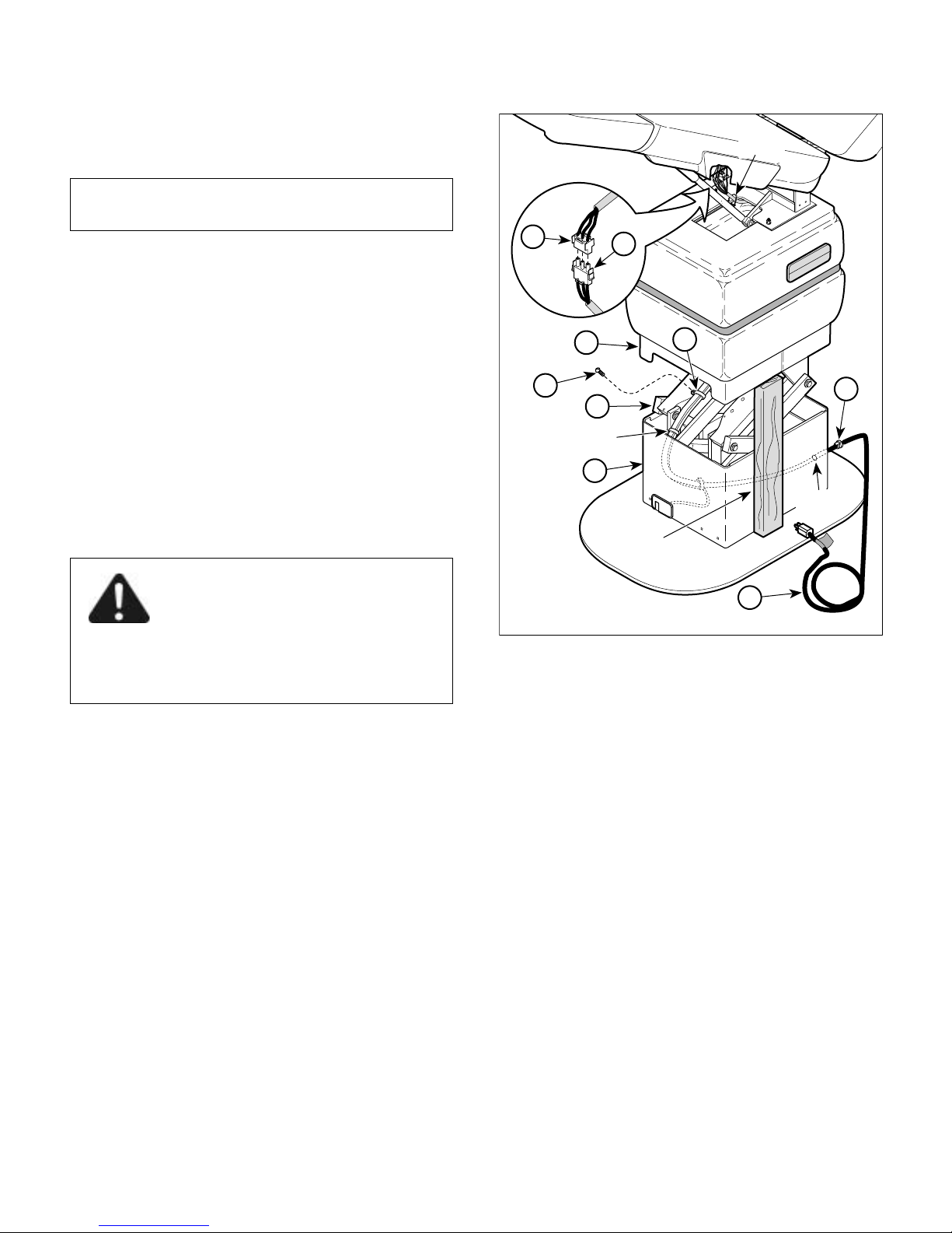
SECTION IV
MAINTENANCE / SERVICE
(4) Place shims (5) in same location on base
subassembly (4) in which they were removed
from.
NOTE
Make sure the shims are held in place by a screw.
(5) Install outer shroud (3) and base outer shroud
(2) as an assembly on base subassembly (4)
and secure with four screws (1).
CABLE
TIE
2
1
417
MIDMARK
(6) Check to make sure there is a piece of protec-
tive trim on each corner of the outer shroud (3).
If not, find and reinstall.
(7) Install table top (Refer to para 4.3).
4.5 Power Cord Removal / Installation
A. Removal
(1) If possible, raise TILT UP function all the way
up.
DANGER
Always unplug the power cord from
the wall outlet before removing any of
the chair's shrouds/covers or making any repairs
to prevent the possibility of electrical shock.
Failure to comply with these instructions could
result in severe personal injury or death.
(2) Unplug power cord from wall outlet.
(3) Disconnect power cord wire harness (1, Figure
4-5) from wire harness (2).
(4) Raise up outer shroud (3) and use a support to
hold it there.
(5) Remove three screws (4) and three wire clips (5)
from base subassembly (6).
(6) Cut cable ties which are securing all wires/wire
harnesses together.
(7) Remove strain relief bushing (7) from inner
shroud (8) and then remove power cord (1) from
chair.
3
5
4
6
CABLE
TIES
8
F
O
O
C
T
O
N
T
R
O
L
C
A
U
TIO
N
D
ET
A
CONTROL
CH
FO
O
N
T
O
W
T IN
HEN
U
SE
WIRE
HOLE
SUPPORT
1
Figure 4-5. Power Cord Removal / Installation
B. Installation
(1) Feed power cord (1) thru wire hole in inner
shroud (8).
(2) Connect power cord wire harness (1) to wire
harness (2).
(3) Secure wires/wire harness to base subassembly
(6) with three wire clips (5) and screws (4).
(4) Secure all wires/wire harnesses together with
cable ties.
(5) Install strain relief bushing (7) around power
cord (1) and then insert strain relief bushing into
wire hole in inner shroud (8).
(6) If chair has been without power for more than
three days, perform the reinitialization procedure
(Refer to para 4.2).
7
MA2481
© Midmark 1994 SF-1399 Page 4-4 Printed in U.S.A.
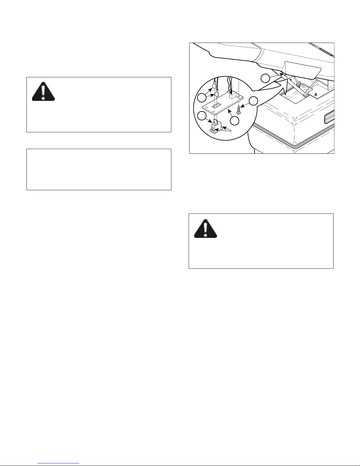
4.6 Control Disable Switch Removal /
TABS
R
Installation
A. Removal
DANGER
Always unplug the power cord from
the wall outlet before removing any of
the chair's shrouds/covers or making any repairs
to prevent the possibility of electrical shock.
Failure to comply with these instructions could
result in severe personal injury or death.
(1) Unplug power cord from wall outlet.
NOTE
Control disable switch can be located on either side
of the chair. The following procedure shows the
switch being removed from the patient's left side of
the chair.
(2) Remove four screws (1, Figure 4-6) and partially
separate control cover (2) from plastic seat
section (3).
(3) Disconnect two wires (4) from control disable
switch (5).
(4) Press on four tabs of of control disable switch
(5), while simultaneously pulling control disable
switch out of control cover (2).
SECTION IV
MAINTENANCE / SERVICE
3
4
5
2
1
MA2482
Figure 4-6. Control Disable Switch
Removal / Installation
4.7 Hand Control Plug-In Port Removal /
Installation
A. Removal
DANGER
Always unplug the power cord from
the wall outlet before removing any of
the chair's shrouds/covers or making any repairs
to prevent the possibility of electrical shock.
Failure to comply with these instructions could
result in severe personal injury or death.
MIDMA
B. Installation
(1) Push control disable switch (5) into control
cover (2) until it "pops" into place, making sure
terminals "1" and "2" are pointing toward foot
end of table.
(2) Connect two wires (4) to control disable
switch (5).
(3) Install control cover (2) on plastic seat section
(3) and secure with four screws (1).
(1) Unplug power cord from wall outlet.
(2) Remove four screws (1, Figure 4-7) and partially
separate control cover (2) from plastic seat
section (3).
(3) Remove clip (4) and hand control port (5) from
control cover (2).
(4) Remove six screws (6) and partially separate
receptacle cover (7) from plastic seat section (3).
(5) Disconnect connector of hand control port (5)
from modular coupler (8).
© Midmark 1994 SF-1399 Page 4-5 Printed in U.S.A.
 Loading...