

Page 1
RETURN TO T ABLE
RETURN TO T ABLE
OF CONTENTS
OF CONTENTS
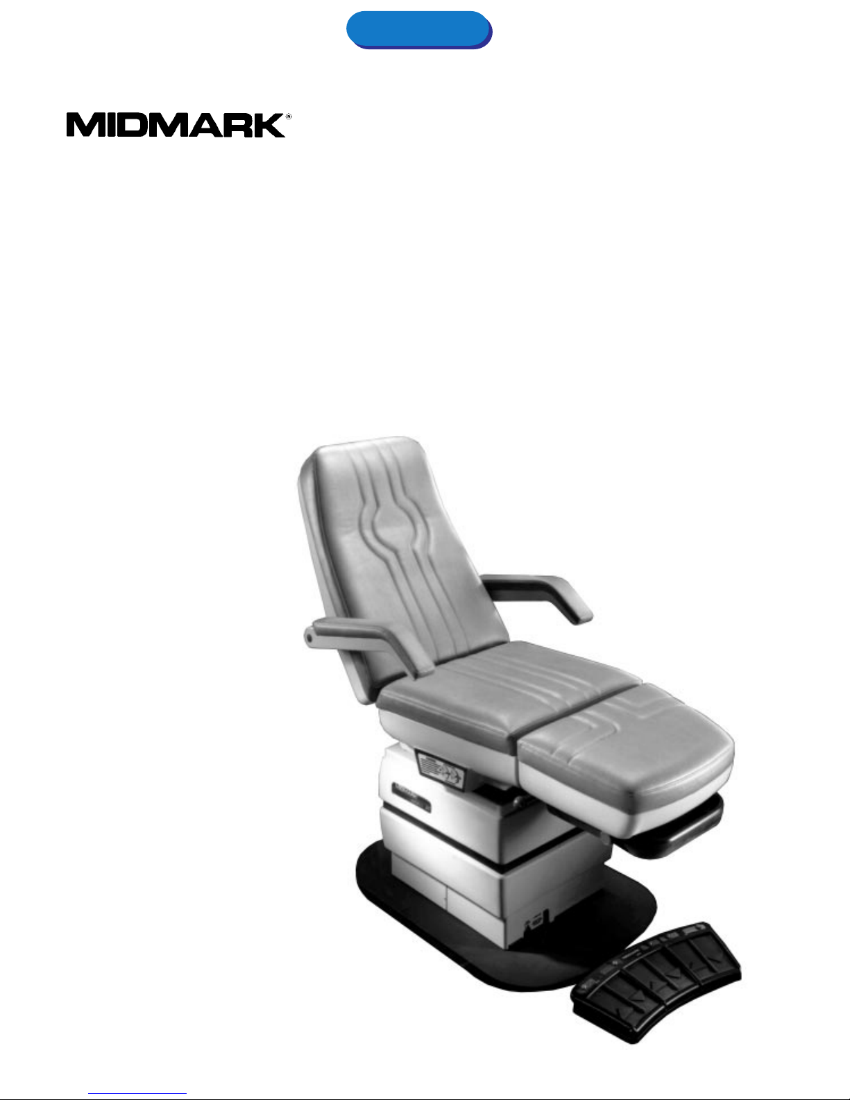
Operation Manual
Model 417 Podiatry Treatment Chair
Installation and
1
Page 2

RETURN TO T ABLE
RETURN TO T ABLE
OF CONTENTS
OF CONTENTS
2
Page 3

RETURN TO HOME PAGE
(or depress Alt and Tab keys)
Contents
General Operation and
Care of Equipment ........................................................ 3
Important Instructions ................................................... 4
Unpacking ..................................................................... 5
Operation of Table’ s Features ........................................ 6
Care of Table ................................................................. 9
Pow er Systems Maintenance........................................ 9
General Operation and Care
of Equipment
This manual covers the instructions for the installation,
operation, and normal care of the 417 Podiatry Examination Chair.
For the purpose of this manual, the word TABLE is
synonymous with the word CHAIR.
This table has been designed to help reduce effort
and work fatigue inv olv ed in the e xamination and treatment of an ever-increasing number of patients during the
doctor’s normal working day.
The angle of the table top , (TILT), and the upper
section of the table, (BA CK), are adjusted by the use of
an electromechanical power unit. The seat height of this
table is fixed at 22-1/2". The angle of the table top,
(TILT), ma y be varied from the horizontal to 30 degrees.
The upper portion of the table, (BACK), can be adjusted
from horizontal to a full chair sitting position, and the foot
section may be manually extended - 8-7/8". The combination of these three motions provide a table which can
not only be tailored to meet the individual doctor’s
requirements, but will meet the requirements of most
examinations and treatments being perfo rmed in the
doctor’s office toda y.
The FOOT CONTROL, accessory p/n 9A97002
(optional) and the HAND CONTROL, accessory p/n
9A93001, (standard) both can be used to control manual
table adjustments and to enter and use preset programmed positions. They also contain an “auto return”
feature which automatically sends the table to a preset,
home, sitting position with the single touch of a button.
The Company shall repair or replace any products or parts thereof, which prove to be defective in workmanship and/or material.
Except as it may otherwise specifically agree in writing the Company shall not be liable for transportation, labor or other charges
for adjustments, repairs, replacement parts, installation or other work which may be done upon or in connection with such products by the Company’s authorized Dealers or others.
Any part or parts of a product to be repaired or replaced under this limited warranty must be returned to the factory f.o.b.
This warranty does not apply to any part or product which examination discloses has been misused, abused, altered or tam-
pered with in any way. This warranty shall be in effect for a period of twelve months from the date of shipment to the customer.
In no event shall the Company be liable for consequential or special damages in the event of warranty repair or replacement
of its products.
THE FOREGOING IS IN LIEU OF ALL WARRANTIES EXPRESSED OR IMPLIED, AND ALL OTHER OBLIGATIONS OR LI-
ABILITIES ON THE PART OF THE COMPANY.
LIMITED W ARRANTY
3
Page 4
Important Instructions
RETURN TO T ABLE
RETURN TO T ABLE
OF CONTENTS
OF CONTENTS
Safety First: The primary concern of the Midmark
Corporation is that this equipment be operated and
maintained with the safety of the patient and doctor in
mind. To assure safer and more reliable operation:
1. Read this manual before installing or operating y our
equipment.
2. It is the responsibility of the purchaser to assure that
appropriate personnel are informed on the contents
of this manual.
W arnings
Throughout this manual are Notes, Cautions, and
Danger paragraphs that call attention to particular
procedures. The items are used as follows:
NO TE
A note is used to amplify an operating procedure,
practice, or condition.
3. Be sure that you understand the instructions contained in this manual before attempting to install or
operate this equipment.
4. This manual should remain permanently affixed to
the equipment.
3. Do not use this table in an explosive or oxygenenriched atmosphere. Using the table in these
situations could cause personal injury or equipment
damage.
4. All exposed metal parts of the table are electrically
grounded. When performing a cauterization or similar
treatment, the patient must be insulated from the
metal portions of the table by a nonconductive
material. Failure to do so could result in electrical
shock or burns to the patient.
CA UTION
A CA UTION is used for an operating
procedure, practice, or condition
which, if not correctly followed, could result in
equipment damage.
D ANGER
A DANGER is used for an operating
procedure, practice, or condition
which, if not correctly followed, could result in
personal injury .
For y our personal safety and that of your patients, all
DANGER warnings are repeated here. Become
thoroughly familiar with them and observe them at
all times.
1. Do not lift at point “B”, fig. 1. This is not a supported
area. Lifting at this point could cause personal injury
or damage to the table.
2. Use 115 volt - 60 hertz alternating current only.
Failure to do so could result in personal injury or
equipment damage.
4
5. If the table malfunctions, immediately remov e y our
foot or hand from the control s witch, unplug the
power cord from the wall receptacle, and assist the
patient from the chair.
6. Keep y our arms and legs and your patient’s arms
and legs clear of all moving parts when changing
table positions. Failure to do so could result in
personal injury .
7. Keep all f oreign objects awa y from the foot switch or
hand control so that the switches are not accidently
activated. F ailure to do so could result in personal
injury or damage to the table.
8. Be sure all persons and equipment are clear of the
table bef ore activ ating the auto return. Failure to do so
could result in personal injury or damage to the table.
9. Be sure all persons and equipment are clear of the
table before activ ating any programmed positions.
Failure to do so could result in personal injury or
equipment damage.
10.Failure to return the foot section or debris tray to its
storage position before lowering or auto returning the
chair tilt could result in personal injury or equipment
damage.
11. Failure to perform a periodic inspection of your
equipment could result in personal injury or equipment damage.
Page 5

RETURN TO T ABLE
RETURN TO T ABLE
OF CONTENTS
OF CONTENTS
Unpacking and Installation
UNPACKING:
To av oid damaging the table when unpacking, do not use
a knife or other sharp object to open the carton. To
begin, break the bands holding down the carton to the
base. Lift carton off the base and remove the poly bag
by pulling the staples loose around the skid. Remove the
4 bolts holding the table to the skid at point “A” and lift
table up out of the skid by points “C”, not at “B”.
C
C
FIGURE 1
B
A
A
DANGER
Do not lift at point “B”, fig. 1. This is
not a supported area. Lifting at this
point could cause personal injury or damage to
the table.
B
DANGER
Do not use this table in an explosive
or oxygen-enriched atmosphere.
Using the table in these situations could cause
personal injury or equipment damage.
DANGER
All exposed metal parts of the table
are electrically grounded. When
performing a cauterization or similar treatment,
the patient must be insulated from the metal
portions of the table by a nonconductive
material. Failure to do so could result in electrical shock or burns to the patient.
The table is now ready for operation. If the table does
not respond to attempts to move the table using the
hand control or foot control, then refer to Reinitialization
on page 8.
ELECTRICAL
The electrical rating of the Model 417 is 115 V.A.C., 60
Hertz, 12 Amperes. The three pronged grounding plug
on the table power cord must be inserted into a matching three-pronged, grounded, non-isolated, correctlypolarized 115-volt receptacle.
The power cord provides pow er to all of the table’s
electromechanical actuators and to both of the duplex
receptacles located on lower sides of the seat (A, Fig. 2).
DANGER
Use 115 volt - 60 hertz alternating
current only. Failure to do so could
result in personal injury or equipment damage.
NOTE
This equipment is not designed for continuous
operation. If the unit is operated continually, a
thermal overload switch will shut off the actuator
motor. If normal operation ceases, immediately
remove your foot or hand from the control s witch.
The overload switch will automatically reset after
the motor cools (minimum 15 minutes).
The 417 table actuators are fused to protect the
operator as well as the table. Should the unit fail to
start after a cool down period, contact an authorized
service center to investigate the cause of the failure .
5
Page 6

RETURN TO T ABLE
RETURN TO T ABLE
OF CONTENTS
OF CONTENTS
Operation of Table Power Features
For optimal perf ormance, allow the tab le to reach room
temperature bef ore operating.
Plug table power cord into proper receptacle as
described above under ELECTRICAL .
NO TE
DISABLE SWITCH: A disab le s witch which interrupts
power to all tab le actuator motors is located
beneath the duplex receptacle on the left-hand side
of the table (B, Fig. 2).
When the switch is positioned to ward the f oot end
of the table, all controls are disabled. Changing the
position of the switch toward the head end of the
table allows po wer to be supplied for tab le positioning.
CA UTION
Alwa ys disable the controls to the table
when it is required to remain in a fixed
position during cauterization or when the table is
left unattended.
To insert plug, align plug tab with notch in the receptacles. Push inward until tab clic ks into the locked
position. To remove plug, depress tab while pulling on
the plug.
A
FIGURE 3
CONTROLS ATTACHMENT:
Insert hand control cord into the receptacle of both the
table, (C, Fig. 2), and into the receptacle in the bottom of
the hand control, (A, Fig. 3). Repeat the process to hook
up the foot control, (Fig. 4).
A
B
C
FIGURE 2
FIGURE 4
NO TE
The table may be operated with the hand control
connected into the foot control receptacle if so
desired, or vice versa.
6
Page 7

RETURN TO T ABLE
RETURN TO T ABLE
OF CONTENTS
OF CONTENTS
NOTE
Turn the disable switch toward the head end to
power up the table, (B, Fig. 2). Then press the
green switch or button mark ed AUT O RETURN.
The table’s actuator motors will run then shut down
automatically. You may now begin to position the
table.
DANGER
If the table malfunctions, immediately
remove your foot or hands from the
control switch, unplug the power cord from the
wall receptacle, and assist the patient from the
table.
DANGER
Keep your arms and legs and yo ur
patient’s arms and legs clear of all
moving parts when changing table position.
Failure to do so could result in personal injury.
CAUTION
The foot control s witches require just
5 lbs. of pressure for activation. Do not
apply excessive force to either the foot control
switches or the hand control panel, which requires
minimal finger pressure.
CAUTION
Do not continue to hold the control
switches down after the table reaches
either of the extreme positions. Extended operation
of the motor at either of these positions will overheat the actuator motor.
ADJUSTMENT OF TABLE B ACK SECTION
To raise the upper portion of the table top from horiz ontal, depress the arrow-switch or button marked BA CK
UP and hold down until the desired position is obtained
or until the table reaches its maximum amount of movement.
To bring the table top , BACK, down toward horizontal,
depress the arrow-switch or button marked BACK
DOWN and hold down until the desired position is
obtained or the horizontal position is achiev ed.
DANGER
Keep all foreign objects away from
the hand control or foot switc h so
that the switches are not accidentally activ ated.
Failure to do so could result in personal injury
or equipment damage.
Patient Positioning (Manual)
The table is now ready for operation. If the table does
not respond to attempts to move the table using the
hand control or foot control, refer to reinitialization steps
on page 8.
Your Model 417 can actuate 3 power motions,
TABLE, BA CK and TIL T.
ADJUSTMENT OF TABLE HEIGHT
To raise the table seat height with either the FOOT
CONTROL OR HAND CONTROL, depress the arrowswitch or button marked TABLE UP and hold down until
the desired position is obtained or until the maximum
height is reached.
To lo w er the tab le seat height, depress the arrowswitch or button marked TABLE DOWN and hold down
until the desired position is obtained or the minimum
seat height is reached.
CAUTION
Do not continue to hold the control
switches down after the table reaches
either of the extreme positions. Extended operation
of the motor at either of these positions will overheat the actuator motor.
FIGURE 5
7
Page 8

RETURN TO T ABLE
RETURN TO T ABLE
OF CONTENTS
OF CONTENTS
ADJUSTMENT OF THE TABLE T OP ANGLE
To tilt the table top, depress the arrow-switch or button
marked TILT UP and hold down until the desired degree
of tilt is obtained or until the table reaches the horizontal
position.
CA UTION
Do not continue to hold the control
switches down after the tab le reaches
either of the extreme positions. Extended operation
of the motor at either of these positions will overheat the actuator motor .
DANGER
Be sure all persons and equipment
are clear of the table before activating
the auto return. Failure to do so could result in
personal injury or equipment damage.
AUTO RETURN
The auto return will lower any amount of table height or
tilt and raise the back, moving simultaneously until the
table reaches a sitting, patient entry or exit, position. To
actuate the auto return, depress the green switch or
button marked AUTO RETURN just once.
Patient Positioning (Programmable)
The table is now ready for operation. If the table does
not respond to attempts to move the tab le using the
hand control or foot control, refer to reinitialization steps
on page 8.
The model 417 table can be programmed to k eep up
to four doctor specified positions in its computer memory.
Once the position is placed in memory , only one switch or
button must be activ ated to simultaneously operate all
three power motions of the table. This allows quick
positioning for frequently perf ormed procedures.
PROGRAMMING THE T ABLE
To store a table position in the computer memory, the
following steps must be taken:
DANGER
Be sure all persons and equipment
are clear of the table before activating
any programmed positions. Failure to do so
could result in personal injury or equipment
damage.
NO TE
For optimal results , alwa ys make certain the table
is in its “home,” auto returned, position bef ore
beginning to enter any programmed positions.
NO TE
If for any reason the AUTO RETURN must be
stopped, press the red switch or button marked
STOP or any other switches or buttons in an
emergency.
REINITIALIZATION
Depress the PROGRAM, POSITION 1, and POSITION 2
switches simultaneously f or a minimum of five seconds.
Release these switches and depress the AUT O
RETURN switch for sev en seconds or until the table
begins to move. Release the AUTO RETURN switch.
The motors will continue to run for approximately eighteen seconds. The table is now ready for normal operation. If table malfunction persists, then contact your
dealer or Midmark’s service department at
1-800-MIDMARK.
1. Using either the foot or hand control, (Fig. 3 & 5),
move the table to the desired position using one
function at a time and without starting and stopping
each function more than once.
2. Press the yellow s witch or b utton marked PROGRAM
once, holding down for 2 or 3 seconds.
3. Next press one of the blue switches or buttons with
the number you choose to assign to this position.
4. Press the green switch or button marked AUT O
RETURN, allow the table to run to the preset home
position.
5. Press the blue, numbered, program switch or button
you hav e just entered and the table will run all
actuators simultaneously until the desired position is
reached.
8
Page 9

RETURN TO T ABLE
RETURN TO T ABLE
NOTE
If for any reason the PROGRAMMED POSITIONING must be stopped, press the red switch or
button marked STOP or any other switches or
buttons in an emergency.
OF CONTENTS
OF CONTENTS
DEBRIS TRA Y
To expose the debris tray for use , simply pull outward.
By loosening the side knobs, (B, Fig. 6), the tray can be
positioned parallel to the floor and locked (knobs tightened). To clean the tray, loosen the knobs and turn it
over or remove it entirely from the chair by lifting the tray
out of the notches in the support arms.
Should the doctor wish to change a PROGRAMMED
POSITION, simply go to the steps listed above. The old
position will be replaced by the new.
In the ev ent of a power outage, your model 417 will
maintain its memory up to four days after the loss of
power.
FOOT SECTION EXTENSION
To accommodate taller patients y our table’s length can
be extended by holding knob, (A, Fig. 6), down while
pulling outward on the foot assembly. Releasing the
knob automatically locks the foot section into the desired
position.
To return the foot section, hold down release knob
and push the foot section assembly inward until it rests
against the seat.
B
DANGER
Failure to return the foot section or
debris tray to its stored position
before lowering or auto returning the table could
result in personal injury or equipment damage.
FIGURE 7
FIGURE 6
A
9
Page 10

RETURN TO T ABLE
RETURN TO T ABLE
OF CONTENTS
OF CONTENTS
Care of Table
CARE OF UPHOLSTERY
The upholstery material used to cover the top of the
table is resistant to most medicinal-type stains, but may
be damaged by solvents and dyes. Regular care should
be maintained by daily wiping with a damp cloth or
sponge and a periodic cleaning with a mild soap and
water solution.
Any fluid spilled on the upholstery should be re-
moved as quickly as possible.
In the case of stain, attempt to remove it with soap
and water.
CARE OF PAINTED METAL SURFACES
All painted metal surfaces should be wiped clean with a
clean, soft cloth weekly, and a periodic application of
paste wax to smooth paints will preserve the finish
luster .
CARE OF PLASTIC COMPONENTS
All the plastic table parts should be cleaned with a clean
damp cloth weekly. Any soiled areas may be cleaned
with soap and water or other household cleaners.
CARE OF MOVING PARTS
All moving parts, such as the foot section slides, back
hinges, and debris tray assembly should be lubricated
occasionally with a light machine oil to help insure quiet,
dependable operation.
Maintenance
Little routine maintenance is required other than a
periodic inspection of the electrical cords to make sure
they are free of cuts or damage and clear of moving
parts. Due to the mechanical, electrical nature of this
equipment, periodic inspections at six (6) month intervals b y your dealer are recommended.
DANGER
Failure to perf orm a periodic inspec-
tion of your equipment could result
in personal injury or equipment damage.
10
Page 11

NOTES
RETURN TO T ABLE
RETURN TO T ABLE
OF CONTENTS
OF CONTENTS
11
Page 12

RETURN TO T ABLE
RETURN TO T ABLE
OF CONTENTS
OF CONTENTS
12
Midmark Corporation, Versailles, Ohio 45380 U.S.A.
937-526-3662 TELEX 288007 FAX 937-526-5542
R
003-0462-00 Rev. D© Copyright by Midmark Corporation 1989
 Loading...