

Page 1
413
Go To Table Of Contents
Place Order
To purchase a printed copy of this manual,
click on the "Place Order" button below.
-001 thru -004
Power Female Procedure
Examination Chair
Serial Number Prefixes:
BK, V, DT & FH
Service and
Parts Manual
FOR USE BY MIDMARK TRAINED TECHNICIANS ONLY
SF-1457 Part No. 004-0003-00 Rev. O (1/01/06)
413
-001
thru
-004
Page 2

Go To Table Of Contents
Page 3

TABLE OF CONTENTS
Section/Paragraph Page Section/Paragraph Page
IMPORTANT INSTRUCTIONS
General Safety Instructions......................................... ii
Safety Alert Symbols .................................................. ii
Warranty Instructions ................................................... ii
SECTION I GENERAL INFORMATION
1.1 Scope of Manual ......................................... 1-1
1.2 How to Use Manual ..................................... 1-1
1.3 Description of 413 Power Female
Procedures Chair ..................................... 1-1
1.4 Specifications ............................................. 1-3
1.5 Parts Replacement Ordering ....................... 1-5
1.6 Special Tools .............................................. 1-5
SECTION II TESTING AND TROUBLESHOOTING
2.1 Operational Test .......................................... 2-1
2.2 Troubleshooting Procedures ........................ 2-2
SECTION III SCHEDULED MAINTENANCE
3.1 Scheduled Maintenance .............................. 3-1
SECTION IV MAINTENANCE/SERVICE
INSTRUCTIONS
4.1 Introduction ................................................. 4-1
4.2 Seat Up Limit Switch Removal /
Installation ................................................ 4-1
4.3 Seat Actuator Removal / Installation ............ 4-2
4.4 Pan Safety Limit Switch Removal /
Installation ................................................ 4-4
4.5 Gas Spring Removal / Installation ................ 4-6
4.6 Base Actuator Removal / Installation ........... 4-7
4.7 Typical Capacitor Removal / Installation ...... 4-9
4.8 Typical Actuator Motor / Actuator Brake
Removal / Installation ............................. 4-10
4.9 Base Down Limit Switch or Seat Down Limit
Switch Removal / Installation .................. 4-11
4.10 Typical Foot Pedal Footswitch Removal /
Installation .............................................. 4-13
SECTION V SCHEMATICS AND DIAGRAMS
5.1 Electrical Schematics / Wiring Diagrams ..... 5-1
SECTION VI PARTS LIST
6.1 Introduction ................................................. 6-1
6.2 Description of Columns ............................... 6-1
6.3 Torque Specifications And Important
Assembly Notes ....................................... 6-1
Pictorial Index .............................................. 6-2
Labels and Decals ........................................ 6-3
Upholstery .................................................... 6-4
Main Frame Section ................................... 6-5.*
Stirrup Assembly ......................................... 6-6
Stirrups ...................................................... 6-7.*
Arm Rest Assembly ...................................6-8.*
Cross Support ............................................ 6-9.*
Base Components .................................... 6-10.*
Base Actuator .......................................... 6-11.*
Base And Panels ..................................... 6-12.*
Linkage Assembly .................................... 6-13.*
Pan Assembly.......................................... 6-14.*
Footrest Assembly ................................... 6-15.*
Seat Components ..................................... 6-16*
Seat Actuator ........................................... 6-17.*
Footswitch ................................................. 6-18
Back Panel .............................................. 6-19.*
Wiring Locations ......................................... 6-20
Export ........................................................ 6-21
COMMENTS ............................................................ 7-1
FAX ORDERING FORM .......................................... 7-2
(*) Indicates that there has been a serial number break for the illustration
and that there are additional point page(s) following the original page.
© Midmark Corporation 1995 SF-1457 Rev. 6/00 Page i Printed in U.S.A.
Page 4

IMPORT ANT INSTRUCTIONS
Return To Table Of Contents
General Safety Instructions
Safety First: The primary concern of Midmark
Corporation is that this Power Female Procedures
Chair is maintained with the safety of the patient and
staff in mind. To assure that services and repairs are
completed safely and correctly, proceed as follows:
(1) Read this entire manual before performing any
services or repairs on this chair.
(2) Be sure you understand the instructions
contained in this manual before attempting to
service or repair this chair.
Safety Alert Symbols
Throughout this manual are safety alert symbols that
call attention to particular procedures. These items are
used as follows:
DANGER
A DANGER is used for an imminently
hazardous operating procedure,
practice, or condition which, if not correctly
followed, will result in loss of life or serious
personal injury.
NOTE
A NOTE is used to amplify an operating procedure,
practice or condition.
Warranty Instructions
Refer to the Midmark “Limited Warranty” printed on the
back cover of the Installation and Operation Manual for
warranty information. Failure to follow the guidelines
listed below will void the warranty and / or render the
413 Power Female Procedures Chair unsafe for
operation.
• In the event of a malfunction, do not attempt to
operate the chair until necessary repairs have been
made.
• Do not attempt to disassemble chair, replace malfunctioning or damaged components, or perform
adjustments unless you are one of Midmark’s
authorized service technicians.
• Do not substitute parts of another manufacturer
when replacing inoperative or damaged components.
Use only Midmark replacement parts.
WARNING
A WARNING is used for a potentially
hazardous operating procedure,
practice, or condition which, if not correctly
followed, could result in loss of life or serious
personal injury.
CAUTION
A CAUTION is used for a potentially
hazardous operating procedure, practice,
or condition which, if not correctly followed, could
result in minor or moderate injury. It may also be
used to alert against unsafe practices.
EQUIPMENT ALERT
An EQUIPMENT ALERT is used for an
imminently or potentially hazardous
operating procedure, practice, or condition which, if
not correctly followed, will or could result in serious,
moderate, or minor damage to unit.
© Midmark Corporation 1995 SF-1457 Page ii Printed in U.S.A.
Page 5

SECTION I
Return To Table Of Contents
GENERAL INFORMATION
SECTION I
GENERAL INFORMATION
1.1 Scope of Manual
This manual contains detailed troubleshooting, scheduled maintenance, maintenance, and service instructions for 413 Power Female Procedures Chair. This
manual is intended to be used by Midmark’s authorized
service technicians.
1.2 How to Use Manual
A. Manual Use When Performing Scheduled Mainte-
nance.
(1) Perform inspections and services listed in
Scheduled Maintenance Chart (Refer to
para 3.1).
(2) If a component is discovered to be faulty or out
of adjustment, replace or adjust component in
accordance with maintenance / service instructions (Refer to para 4.1).
B. Manual Use When Chair Is Malfunctioning And
Cause Is Unknown.
(1) Perform an operational test on chair (Refer to
para 2.1).
(2) Perform troubleshooting procedures listed in
Troubleshooting Guide (Refer to para 2.2).
(3) If a component is discovered to be faulty or out
of adjustment, replace or adjust component in
accordance with maintenance / service instructions (Refer to para 4.1).
examinations and procedures on female patients;
especially Lithotomy procedures.
The major serviceable components of the chair are the
seat actuator, seat capacitor, base actuator, base
capacitor, gas spring, pan safety limit switch, seat up
limit switch, seat down limit switch, base down limit
switch, and the foot control which includes four foot
switches.
B. Theory of Operation (See Figure 5-1, Sheets 1
and 2 for domestic wiring diagrams, Figure 5-2,
Sheets 1 and 2 for export wiring diagrams, Figure
5-3 for domestic electrical schematic, and Figure 54 for export electrical schematic.)
Electrical Power:
Line voltage is supplied directly to the footswitches of
the chair. Also, line voltage is always present at the
receptacle (domestic units only).
Chair Operation:
Power is present at all four foot control footswitches.
However, the BASE DOWN and SEAT UP switches
receive their power thru the BASE UP and SEAT
DOWN footswitches, respectively. So, if the BASE UP
footswitch is depressed, power is removed from the
BASE DOWN footswitch and if the SEAT DOWN
footswitch is depressed, power is removed from the
SEAT UP footswitch. This wiring setup prevents the
operator from trying to run the actuator in an up and
down direction simultaneously and causing damage to
the actuator.
C. Manual Use When Damaged Component Is Known.
(1) Replace or adjust component in accordance
with maintenance / service instructions (Refer
to para 4.1).
1.3 Description Of 413 Power Female
Procedures Chair
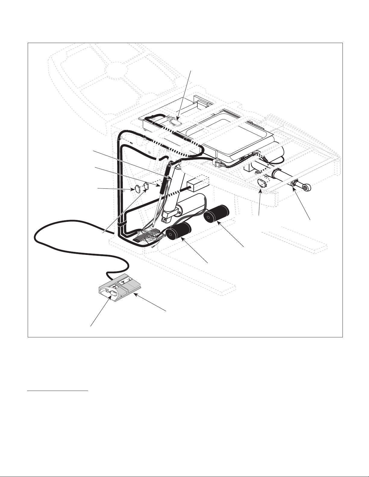
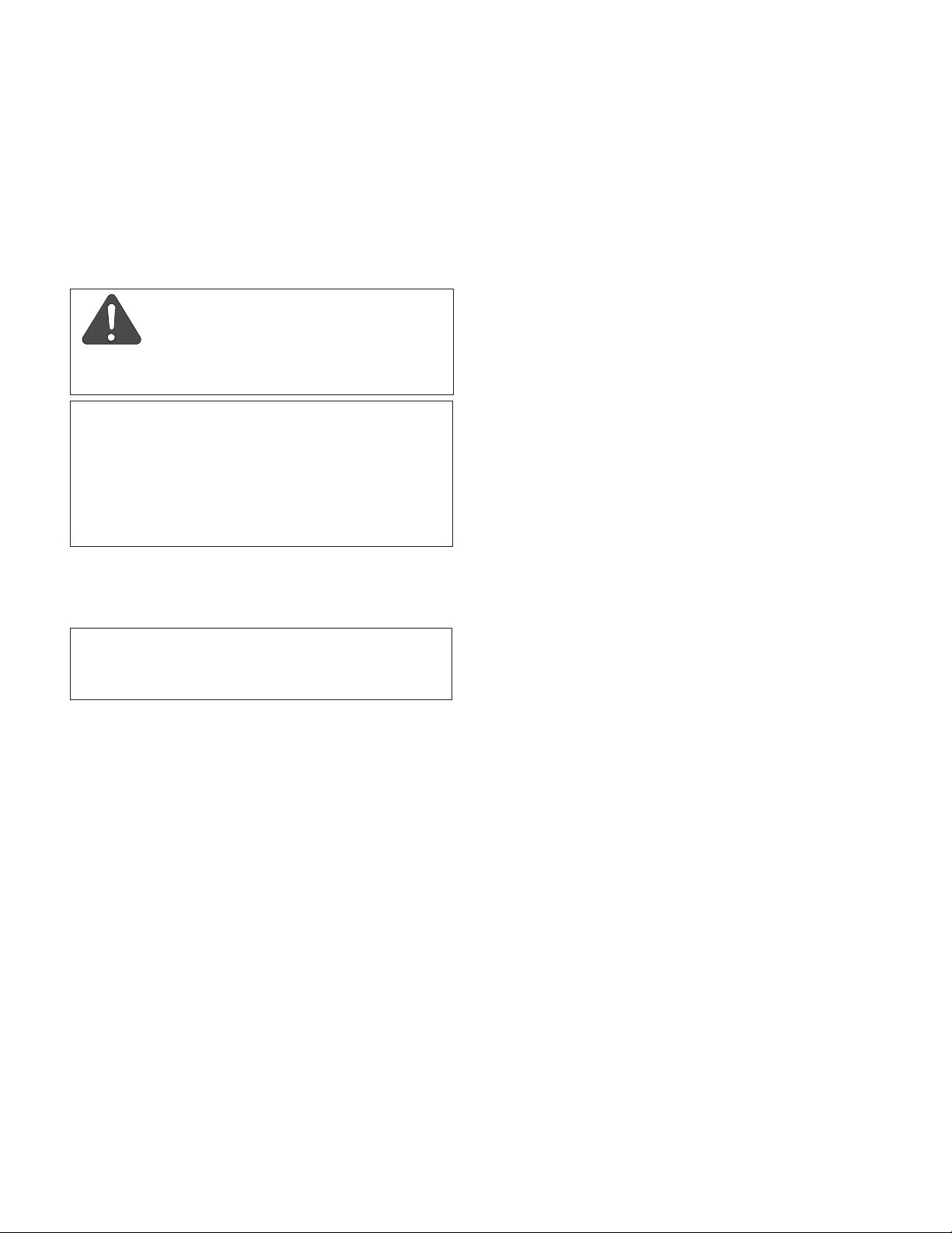
A. General Description (See Figure 1-1).
The 413 Power Female Procedures Chair is an examination chair designed for performing female specific
© Midmark Corporation 1995 SF-1457 Page 1-1 Printed in U.S.A.
SEAT UP function:
When the operator depresses the SEAT UP footswitch,
current is applied across the seat actuator motor
windings thru the normally open (N.O.) pan safety limit
switch and seat capacitor, causing the seat actuator to
run. The pan safety limit switch is a N.O switch. When
the pan assembly is in its stowed position, the pan
safety limit switch is tripped, closing the circuit and
allowing the seat actuator to run. If the pan assembly is
not in its stowed position, the pan safety limit switch is
not tripped, which opens the circuit and prevents the
seat actuator from running. This prevents the operator
Page 6
SECTION I
Return To Table Of Contents
GENERAL INFORMATION
BASE ACTUAT OR
GAS SPRING
BASE DOWN
LIMIT SWITCH
PAN SAFETY
LIMIT SWITCH
SEAT DOWN
LIMIT SWITCH
RETURN
RETURN
AQUIRE
AQUIRE
FOOT CONTROL
FOOT SWITCH
Figure 1-1. Major Components
from running the foot section into the pan assembly and
damaging it. The seat capacitor provides motor start
and motor run power for the seat actuator.
BASE DOWN function:
When the BASE DOWN footswitch is depressed,
current is applied across the base actuator motor coil
thru either the seat up limit switch or the base down
limit switch and base capacitor, causing the base
SEAT UP
LIMIT SWITCH
SEAT ACTUATOR
SEAT CAPACITOR
BASE CAPACITOR
MA317900
actuator to run. The seat up limit switch is a normally
closed (N.C.) switch which is tripped when the seat
function is in any position, but all the way up, resulting
in an open circuit. This prevents the operator from
running the BASE DOWN function (lower than the 2/3
up position - see base down limit switch operation)
when the seat is in any position, but all the way up,
preventing an accidental seat section collision with
floor. When the seat function is raised all the way up,
the seat up limit switch untrips, closing the circuit, and
© Midmark Corporation 1995 SF-1457 Page 1-2 Printed in U.S.A.
Page 7

SECTION I
Return To Table Of Contents
GENERAL INFORMATION
allowing the BASE DOWN function to be operated to
any position.
The base down limit switch is a N.C. switch which is
tripped when the base function is between the all the
way down position to approximately the 2/3 up position,
resulting in an open circuit. This means that the switch
is untripped only when the base function is in 2/3 up
position to all the way up position, resulting in a closed
circuit. This only allows the operator to lower the BASE
DOWN function down to the 2/3 up position. Then the
base down limit switch trips, opening the circuit, and
preventing further downward movement of the base
actuator. This prevents an accidental seat section
collision with floor. The base capacitor provides motor
start and motor run power for the base actuator.
So, if the seat up limit switch is tripped (seat function
not
in all the way up position), the base down limit
switch provides the base actuator with current; this
allows you to lower table top only 1/3 of way down. But,
if the seat up limit switch is untripped (seat function is in
all the way up position), the seat up limit switch provides the base actuator with current; this allows you to
lower table top all the way down.
BASE UP function:
When the BASE UP footswitch is depressed, current is
applied across the base actuator motor coil and base
capacitor, causing the base actuator to run. The base
capacitor provides motor start and motor run power for
the base actuator.
is
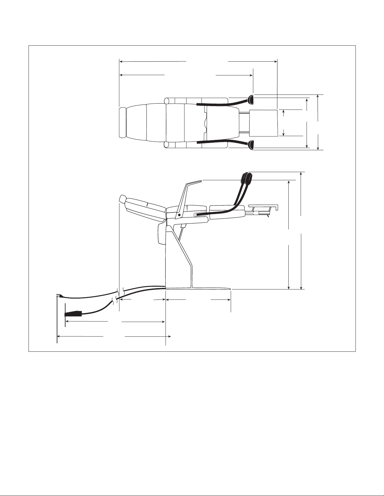
1.4 Specifications
Factual data for the 413 Female Procedures Chair is
provided in Table 1-1. Also, see Figure 1-2.
Table 1-1. Specifications
Description Data
Weight:
Without Shipping Carton ................ 374 lb (169.6 kg)
With Shipping Carton ..................... 412 lb (186.9 kg)
Shipping Carton ....... 55 in. "L" x 33 in. "W" x 44 in. "H"
(139.7 cm x 83.8 cm x 111.7 cm)
Dimensions (See Figure 1-2):
Table Top Length (w/o foot section
extended) ................................... 55.5 in. (141.0 cm)
Table Top Length (w/ foot section
fully extended) ............................ 72.7 in. (184.6 cm)
Table Top Width (w/ armrests) .......... 28 in. (71.1 cm)
Maximum width of upholstery ............. 22 in. (55.9 cm)
Overall Width ..................................... 28 in. (71.1 cm)
Chair Positioning:
Seat height in chair position ................ 19 in. (48.3 cm)
Height in table position ....................... 34 in. (86.4 cm)
Maximum pelvic area height ............... 36 in. (91.4 cm)
Chair Speeds (@ 60 Hz.):
Base Up ................................................ 9 ±1 seconds
Seat Up ................................................. 9 ±1 seconds
SEAT DOWN function
When the SEAT DOWN footswitch is depressed,
current is applied across the seat actuator motor coil
thru the seat down limit switch and seat capacitor. The
seat down limit switch is a N.C. switch which is tripped
when the base function is between the all the way down
position to approximately the 2/3 up position, resulting
in an open circuit. This means that the switch is
untripped only when the base function is in the 2/3 up
position to all the way up position, resulting in a closed
circuit. This only allows the operator to lower the SEAT
DOWN function if the base actuator is in 2/3 up position
or higher. This prevents an accidental seat section
collision with floor. The seat capacitor provides motor
start and motor run power for the seat actuator.
© Midmark Corporation 1995 SF-1457 Rev. 7/98 Page 1-3 Printed in U.S.A.
Weight Capacity (Maximum)............. 300 lb. (136.0 kg)
Electrical Requirements:
115 VAC Unit........................... 110 - 120 VAC, 60 HZ,
6 amp, single phase
230 VAC Unit...................... 220 - 240 VAC, 50/60 HZ,
5 amp, single phase
Power Consumption:
115 VAC Unit ........................................... 720 WATTS,
6 amps @ 120 VAC
230 VAC Unit........................................ 1200 WATTS,
5 amps @ 240 VAC
Recommended Circuit:
A separate (dedicated) circuit is recommended for
this chair. The chair
electrical circuit with other appliances or equipment
unless the circuit is rated for the additional load.
should not
be connected to an
Page 8
SECTION I
Return To Table Of Contents
GENERAL INFORMATION
68 in. (172.7 cm.)
53 1/4 in. (135.2 cm.)
16 in.
40.6 cm.
22 in.
(55.9 cm.)
33 3/4 in.
(85.7 cm.)
72 in
(182.9 cm.)
100 in.
(254 cm.)
19 5/8 in.
(49.8 cm.)
30 3/4 in.
(78.1 cm.)
Figure 1-2. Chair Dimensions
50 in.
(127 cm.)
44 1/2 in.
(113 cm.)
MA318000
© Midmark Corporation 1995 SF-1457 Page 1-4 Printed in U.S.A.
Page 9
1.5 Parts Replacement Ordering
MODEL NO. 413-00X
INPUT. 120 VAC.
RATING 6 AMPS 60 Hz
SERIAL NO. XXXXXX
FOR SALES OR SERVICE CALL 1-800-XXX-XXXX MADE IN THE U.S.A.
MIDMARK
Return To Table Of Contents
If a part replacement is required, order the part directly
from the factory as follows:
(1) Refer to Figure 1-3 to determine the location of
the model number and serial number of the
chair and record this data.
(2) Refer to the Parts List to determine the item
numbers of the parts, part numbers of the
parts, descriptions of the parts, and quantities
of parts needed and record this data (Refer to
para 6.1).
NOTE
Ask the Purchasing Department of the company that
owns the chair for this information. Otherwise, this
information may be obtained from the dealer that
sold the chair.
SECTION I
GENERAL INFORMATION
(3) Determine the installation date of the chair and
record this data.
(4) Call Midmark with the recorded information and
ask for the Medical Products Technical Services Department. See back cover of this
manual for the phone number or use the Fax
Order Form (See page 7-2 for Fax Order
Form).
1.6 Special Tools
Table 1-2 lists all of the special tools needed to repair
the chair, how to obtain the special tools, and the
purpose of each special tool.
Description of Special Tool
Multimeter Commercially Available Any Type Used to perform continuity and voltage checks.
Torque Wrench Commercially Available Any Type Used to tighten hardware to specified torque
Manufacturer’s
Name / Address / Phone
MA309302
Figure 1-3. Model Number / Serial
Table 1-2. Special Tool List
Manufacturer’s
Part Number
Number Location
Purpose of Special Tool
values.
© Midmark Corporation 1995 SF-1457 Page 1-5 Printed in U.S.A.
Page 10

SECTION I
Return To Table Of Contents
GENERAL INFORMATION
© Midmark Corporation 1995 SF-1457 Page 1-6 Printed in U.S.A.
Page 11
TESTING AND TROUBLESHOOTING
Return To Table Of Contents
SECTION II
TESTING AND TROUBLESHOOTING
SECTION II
2.1 Operational Test
In order to effectively diagnose the malfunction of the
chair, it may be necessary to perform an operational
test as follows:
DANGER
Refer to the Operator Manual for
complete instructions on operating the
chair. Failure to do so could result in personal
injury.
NOTE
The Operational Test, for the most part, only describes what should happen when the chair is
operated. If the chair does something other than
described, a problem has been discovered. Refer to
the Troubleshooting Guide to determine the cause of
the problem and its correction.
(1) Plug the chair into a grounded, non-isolated,
correctly polarized outlet, that has the proper
voltage output for the chair.
(7) Depress BASE DOWN footswitch and lower
table top all the way down; then depress SEAT
DOWN footswitch.
(8) Observe. After the BASE DOWN function is
lowered all the way down, the seat actuator
should not run when the SEAT DOWN
footswitch is depressed.
(9) Run BASE UP function all the way up and then
run SEAT DOWN function all the way down.
(10) Pull the pan holder assembly outward until pan
safety limit switch is no longer tripped. Depress
SEAT UP footswitch and then SEAT DOWN
footswitch.
(11) Observe. The seat section of table top
not
move when the SEAT UP and SEAT
DOWN footswitches are depressed.
(12) Push pan holder assembly inward until pan
safety limit switch is tripped. Depress SEAT
UP and SEAT DOWN footswitches.
should
NOTE
Pan holder assembly should be pushed in fully for
the following step.
(2) Depress BASE UP, SEAT DOWN, SEAT UP,
and BASE DOWN footswitches in this order.
(3) Observe. The table top should move in the
direction corresponding to the footswitch which
is being depressed and at the speeds listed
below:
Chair Speeds (@ 60 Hz.):
Base Down to Base Up in 9 +/1 seconds
Seat Down to Seat Up in 9 +/1 seconds
The actuator assembly should not drift after the
footswitch is released. The actuator assembly
should not make excessive squealing noises.
(4) Raise BASE UP function all the way up.
(5) Depress SEAT DOWN footswitch and lower
seat section halfway. Then raise SEAT UP
function all the way up.
(6) Observe. Seat actuator should run.
(13) Observe. The seat section of table top
move when the SEAT UP and SEAT DOWN
footswitches are depressed.
(14) Lower the SEAT DOWN function all the way
down.
(15) Depress and hold the BASE DOWN footswitch.
(16) Observe. The BASE DOWN function should
lower approximately 1/3 of its travel and then
stop.
(17) Raise the SEAT UP function all the way up.
(18) Depress the BASE DOWN footswitch.
(19) Observe. The BASE DOWN function should
lower all the way down.
(20) Pull the release handle and extend the foot
extension. Then, pull the release handle and
push the foot extension back into foot section.
should
© Midmark Corporation 1995 SF-1457 Page 2-1 Printed in U.S.A.
Page 12
SECTION II
Return To Table Of Contents
TESTING AND TROUBLESHOOTING
RELEASE
BUTTON
PAN HOLDER
ASSEMBLY
SEAT
SECTION
FOOT
EXTENSION
ARM
REST
Figure 2-1. Operational Test
(21) Observe. The foot extension should slide out
easily and quietly. The foot extension should
automatically lock into a fully extended position.
When the foot extension is pushed into the foot
section, the foot extension should automatically
lock into a stowed position.
RELEASE
HANDLE
BASE DOWN
SEAT UP
SEAT DOWN
BASE UP
MA316500
(24) Raise arm rest upward and then release.
(25) Observe. The arm rest should automatically
lock into its normal position.
2.2 Troubleshooting Procedures
(22) Press the arm rest release button and lower the
arm rest.
(23) Observe. When the release button is pressed,
the arm rest should be able to be lowered.
© Midmark Corporation 1995 SF-1457 Page 2-2 Printed in U.S.A.
Table 2-1 is a Troubleshooting Guide which is used to
determine the cause of the malfunction.
Page 13

TESTING AND TROUBLESHOOTING
Return To Table Of Contents
Table 2-1. Troubleshooting Guide
Problem Symptom Probable Cause Check Correction
Table will not operate
when any of the Base
or Seat up or down
functions are
selected.
SEAT UP function
does not work, but
SEAT DOWN
function does.
SEAT DOWN
function does not
work, but SEAT UP
function does.
When a foot control
footswitch is depressed,
its actuator motor does
not run or hum.
When SEAT UP
footswitch is depressed,
nothing happens.
When SEAT DOWN
footswitch is depressed,
nothing happens.
Power cord is not plugged into
facility wall outlet.
Facility circuit breaker
providing power to chair is
tripped.
One or both fuses in AC
connector receptacle is blown
(export models only).
Wire connections loose. Check all wiring
SEAT UP footswitch is
malfunctioning.
SEAT DOWN footswitch is
sticking open.
SEAT DOWN footswitch is
malfunctioning.
Seat down limit switch is
tripped.
Seat down limit switch is
malfunctioning.
Check to see if power cord
is plugged in.
Check to see if facility
circuit breaker is tripped.
One way of checking this is
to plug a lamp into wall
outlet that chair was
plugged into.
Refer to Figure 5-2, Sheets
1 or 2 for fuse information.
Perform continuity check on
fuse.
connections from power
cord to terminal block.
Perform continuity check on
wires. Use multimeter to
check for proper voltage
levels.
Perform continuity check on
SEAT UP footswitch.
When footswitch is
activated, there should be
continuity between COM.
and N.O. terminals of
footswitch.
Perform continuity check on
SEAT DOWN footswitch.
When footswitch is not
activated, there should be
continuity between COM.
and N.C. terminals of
footswitch.
Perform continuity check on
SEAT DOWN footswitch.
When footswitch is
activated, there should be
continuity between COM.
and N.O. terminals of
footswitch.
Check if seat down limit
switch is tripped. Seat
down limit switch should be
tripped when base actuator
is in all the way down
position to 2/3 up position.
This prevents operator from
accidentally colliding seat
section with floor.
Perform continuity check on
N.C. seat down limit
switch. Switch tripped =
p
Plug power cord into
facility wall outlet.
If circuit breaker is
tripped, determine what
caused circuit breaker to
trip, correct the problem,
and then reset / replace
circuit breaker.
Replace any blown
fuses.
Clean any dirty
connections. Tighten
any loose connections.
Replace any damaged
connections.
Replace SEAT UP
footswitch. Refer to
para 4.10.
Replace SEAT DOWN
footswitch. Refer to
para 4.10.
Replace SEAT DOWN
footswitch. Refer to
para 4.10.
Raise BASE UP function
until it is at least 2/3 of
the way up in its travel.
Then SEAT DOWN
function will work.
Inform operator of the
seat down limit switch
function.
Replace seat down limit
switch. Refer to para
4.9.
SECTION II
© Midmark Corporation 1995 SF-1457 Page 2-3 Printed in U.S.A.
Page 14

SECTION II
Return To Table Of Contents
TESTING AND TROUBLESHOOTING
Table 2-1. Troubleshooting Guide - Continued
Problem Symptom Probable Cause Check Correction
SEAT UP and SEAT
DOWN functions do not
work.
BASE DOWN function
does not work, but BASE
UP function does.
When SEAT DOWN or
SEAT UP footswitch is
depressed, nothing
happens.
When BASE DOWN
footswitch is depressed,
nothing happens.
Wire connections loose. Check all wiring
Treatment pan assembly is
not pushed in all the way.
Pan safety limit switch is
malfunctioning.
Seat capacitor is weak or
blown.
Thermal overload switch in
seat actuator motor is
activated.
Seat actuator assembly is
malfunctioning.
BASE DOWN footswitch is
malfunctioning.
BASE UP footswitch is
sticking open.
Base down limit switch is
tripped.
connections from SEAT
DOWN footswitch to
terminal block. Perform
continuity check on wires.
Use multimeter to check for
proper voltage levels.
Check if treatment pan
assembly is pushed all the
way in to its stowed
position.
Perform continuity check on
pan safety limit switch.
Switch tripped = closed
circuit or continuity.
Replace suspect seat
capacitor with known
working seat capacitor.
__ Wait 10 to 20 minutes to allow
Replace suspect seat
actuator assembly with
known working seat
actuator assembly.
Perform continuity check on
BASE DOWN footswitch.
When footswitch is
activated, there should be
continuity between COM.
and N.O. terminals of
footswitch.
Perform continuity check on
BASE UP footswitch.
When footswitch is not
activated, there should be
continuity between COM.
and N.C. terminals of
footswitch.
Check if base down limit
switch is tripped. Base
down limit switch will be
tripped when base actuator
is lowered below the 2/3 up
position. This removes
current from base actuator if
N.C seat up limit switch is
also tripped. This prevents
operator from accidentally
colliding seat section with
floor.
Clean any dirty connections.
Tighten any loose
connections. Replace any
damaged connections.
Push treatment pan assembly
all the way in. Inform
operator on how this function
works.
Replace pan safety limit
switch. Refer to para 4.4.
Replace seat capacitor.
Refer to para 4.7.
seat actuator motor to cool.
Replace seat actuator
assembly. Refer to para 4.3.
Replace BASE DOWN
footswitch. Refer to para
4.10.
Replace BASE UP footswitch.
Refer to para 4.10.
Raise SEAT UP function all
the way up to untrip seat up
limit switch. Then BASE
DOWN function can be
lowered all the way down.
Inform the operator how this
function works.
© Midmark Corporation 1995 SF-1457 Rev. 9/97 Page 2-4 Printed in U.S.A.
Page 15

TESTING AND TROUBLESHOOTING
Return To Table Of Contents
Table 2-1. Troubleshooting Guide - Continued
Problem Symptom Probable Cause Check Correction
BASE DOWN function
does not work, but
BASE UP function does
- Continued.
BASE UP function does
not work, but BASE
DOWN function does.
BASE UP and BASE
DOWN functions do not
work.
When BASE DOWN
footswitch is depressed,
nothing happens Continued.
When BASE UP
footswitch is depressed,
nothing happens.
When BASE UP or BASE
DOWN footswitch is
depressed, nothing
happens.
Base down limit switch is
malfunctioning.
Seat up limit switch is
malfunctioning.
BASE UP footswitch is
malfunctioning.
Gas spring is
malfunctioning.
Wire connections loose. Check all wiring
Base capacitor is weak or
blown.
Perform continuity
check on N.C. base
down limit switch.
Switch tripped = open
circuit. Base down limit
switch is tripped when
base actuator is in all
the way down position
to 2/3 up position.
Perform continuity
check on N.C. seat up
limit switch. Switch
tripped = open circuit.
Seat up limit switch is
untripped only when
seat section is all the
way up.
Perform continuity
check on BASE UP
footswitch. When
footswitch is activated,
there should be
continuity between
COM. and N.O.
terminals of footswitch.
Replace suspect gas
spring with known
working gas spring.
connections from BASE
UP footswitch to
terminal block. Perform
continuity check on
wires. Use multimeter
to check for proper
voltage levels.
Replace suspect base
capacitor with known
working base capacitor.
Replace base down limit
switch. Refer to para 4.9.
Replace seat up limit switch.
Refer to para 4.2.
Replace BASE UP
footswitch. Refer to para
4.10.
Replace gas spring. Refer
to para 4.5.
Clean any dirty connections.
Tighten any loose
connections. Replace any
damaged connections.
Replace base capacitor.
Refer to para 4.7.
SECTION II
© Midmark Corporation 1995 SF-1457 Page 2-5 Printed in U.S.A.
Thermal overload switch in
base actuator motor is
activated.
Base actuator assembly is
malfunctioning.
_ Wait 10 to 20 minutes to
Replace suspect base
actuator assembly with
known working base
actuator assembly.
allow base actuator motor to
cool.
Replace base actuator
assembly. Refer to para
4.6.
Page 16

SECTION II
Return To Table Of Contents
TESTING AND TROUBLESHOOTING
Table 2-1. Troubleshooting Guide - Continued
Problem Symptom Probable Cause Check Correction
Chair moves fine for light
patient, but will not move
or moves slowly for very
heavy patient.
Heavy patients cause
table to malfunction.
Low voltage is being
supplied to chair.
Table overloaded with too
heavy of a patient.
Check voltage at wall
receptacle - should be
115 +/- 5 VAC for
domestic units and 230
+/- 10 VAC for export
units.
Maximum weight
capacity of table is 300
lbs (136.0 kg).
Correct low voltage situation
at wall receptacle.
Inform chair operator of
weight limitation.
Whirling or squeaking
noise is heard when an
actuator assembly is
being run.
Foot extension locking
mechanism is
malfunctioning.
Capacitor for suspect
function is weak.
Noisy actuator. Foreign matter on ball
Foot extension does not
lock into stowed position
or extended position
automatically.
screw threads and / or lack
of lubricant.
Foot extension lock /
unlock mechansim is
malfunctioning.
Replace suspect
capacitor with known
working capacitor.
Check for foreign
matter on ball screw
threads. Check for lack
of lubricant on ball
screw threads.
Check to see if return
spring is present.
Check to see if linking
rod is present.
Replace capacitor. Refer to
para 4.7.
Clean all foreign matter off
of ball screw threads. Coat
ball screw threads with STP
treatment oil or equivalent.
If actuator assembly is still
noisy, replace. Refer to
para 4.3 or 4.6.
Lubricate mechansim with a
silicone based lubricant.
Replace missing, worn, or
broken return spring or
linking rod.
© Midmark Corporation 1995 SF-1457 Page 2-6 Printed in U.S.A.
Page 17

SCHEDULED MAINTENANCE
Return To Table Of Contents
SECTION III
SCHEDULED MAINTENANCE
SECTION III
3.1 Scheduled Maintenance
periodically on the chair. These inspections and
services should be performed as often as indicated in
Table 3-1 is a Scheduled Maintenance Chart which lists
the chart.
the inspections and services that should be performed
Table 3-1. Scheduled Maintenance Chart
Interval Inspection or Service What to Do
Semi-annually Obvious damage Visually check condition of chair for obvious damage such as: cracks in components, missing
Fasteners/hardware Check chair for missing or loose fasteners / hardware. Replace any missing hardware and
Warning and
instructional decals
Pivot points / moving
parts / accessories
Foot control Check that foot control works correctly. Make sure all footswitches operate properly.
Ball screws of actuator
assemblies
Inner tube of base
actuator
Drifting of actuator
assemblies
Foot extension Check that foot extension automatically locks into stowed and extended positions. Lubricate
Pan safety limit switch Check that pan safety limit switch is tripped when pan assembly is in fully stowed position.
Electrical receptacle
(domestic units only)
Upholstery Check all upholstery for rips, tears, or excessive wear. Replace cushions as necessary.
Accessories Check that all accessories have all of their components and that they function properly. If
Operational Test Perform an Operational Test to determine if the chair is operating within its specifications
components, dents in components, or any other visible damage which would cause chair to
be unsafe to operate or would compromise its performance. Repair chair as necessary.
tighten any loose hardware as necessary.
Check for missing or illegible decals. Replace decals as necessary.
Lubricate all exposed pivot points, moving parts, and accessories with silicone based
lubricant.
Replace any malfunctioning footswitches. Refer to para 4.10.
Extend each actuator assembly and wipe ball screw threads down with a rag to remove
foreign matter. Coat as much of the ball screw threads as possible with STP treatment oil or
equivalent. Run each actuator assembly to both ends of its travel a couple of times to
spread the oil evenly over all of the ball screw threads and then remove excess oil. If oil
does not correct a squealing actuator assembly, replace actuator assembly. Refer to para
4.3 or 4.6.
Lubricate inner tube of base actuator with vaseline.
Check each actuator assembly for drift. Replace actuator assembly brake components as
necessary. Refer to para 4.8.
linkages with a silicone based lubricant.
Adjust or replace pan safety limit switch if necessary. Refer to para 4.4.
Check that the electrical receptacle is functioning properly. Replace receptacle as
necessary.
necessary, repair or replace the accessory.
p
p
p
© Midmark Corporation 1995 SF-1457 Page 3-1 Printed in U.S.A.
Page 18

SECTION III
Return To Table Of Contents
SCHEDULED MAINTENANCE
© Midmark Corporation 1995 SF-1457 Page 3-2 Printed in U.S.A.
Page 19
MAINTENANCE / SERVICE
EARLY UNITS
3A
4
5
4
6
7
1
LATER UNITS
4
3B
EARLY UNITS
3A
4
Return To Table Of Contents
SECTION IV
MAINTENANCE / SERVICE INSTRUCTIONS
SECTION IV
4.1 Introduction
DANGER
Refer to the Operator Manual for
complete instructions on operating the
chair. Failure to do so could result in personal
injury.
NOTE
Perform an operational test on the chair after the
repair is completed to confirm the repair was properly
made and that
The following paragraphs contain removal, installation, repair, and adjustment procedures for the chair.
all
malfunctions were repaired.
4.2 Seat Up Limit Switch Removal / Installation
A. Removal
(1) Raise TABLE UP and SEAT UP functions all
the way up.
LATER UNITS
3B
4
5
4
6
7
1
2
DANGER
Always disconnect the power cord
from the wall outlet before removing
any of the chair's covers/shrouds or making any
repairs to prevent the possibility of electrical
shock. Failure to comply with these instructions
could result in severe personal injury or death.
(2) Unplug chair power cord from wall outlet.
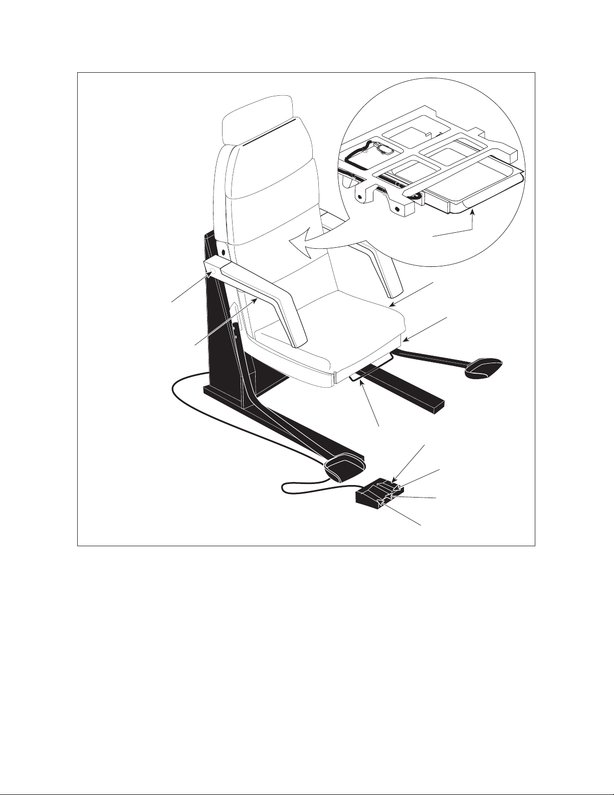
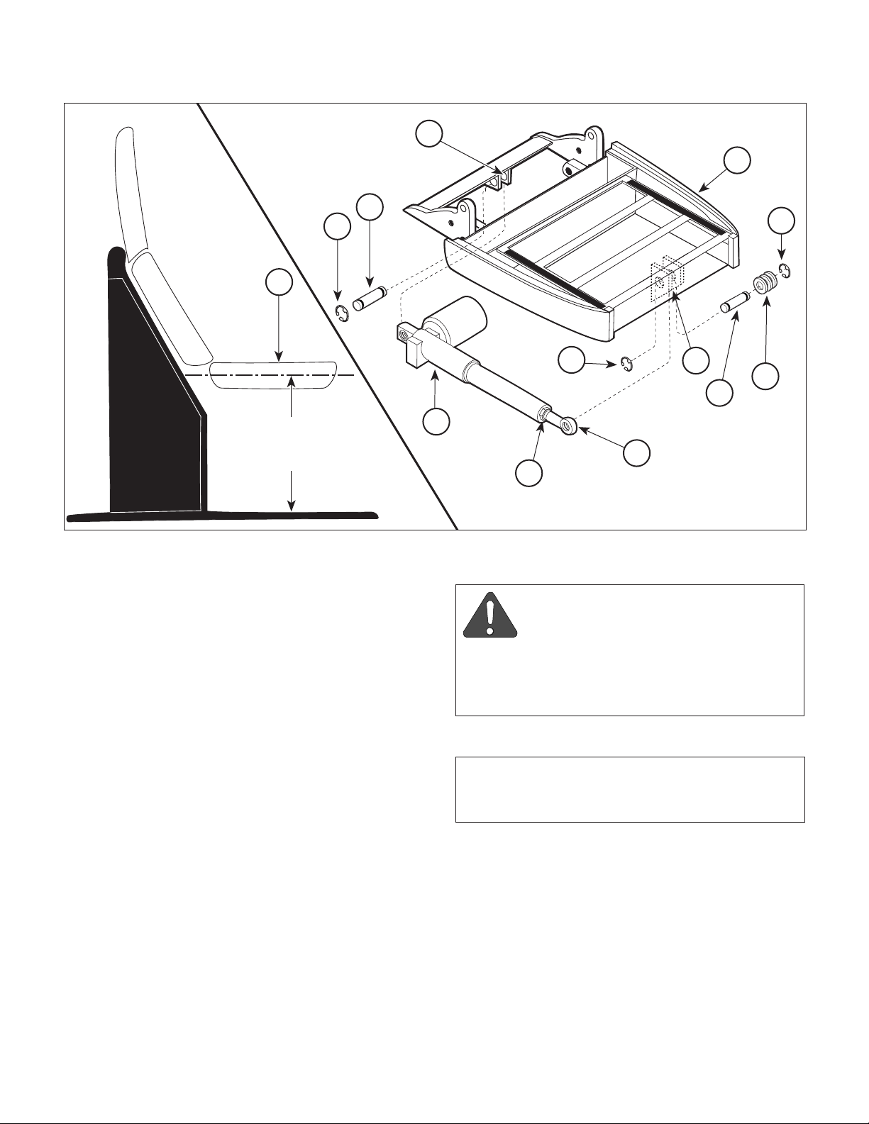
(3) Cut two cable ties and remove actuator sleeve
(1, Figure 4-1) from shaft of seat actuator (2).
(4) On early units, tag and disconnect two wires
(3A) from terminals of seat up limit switch (4).
On later units, disconnect wire harness (3B)
from seat up limit switch (4).
(5) Remove two nuts (5), screws (6), and seat up
limit switch (4) from switch bracket (7).
CABLE TIES
VIEW
MA316600
Figure 4-1. Seat Up Limit Switch
Removal / Installation
B. Installation
NOTE
With SEAT UP function all the way up, seat up limit
switch should be untripped. Make sure seat up limit
switch is installed to meet this condition.
(1) Install seat up limit switch (4) on switch bracket
(7) and secure with two screws (6) and
nuts (5), making sure trip arm of switch is in
cutout of seat actuator shaft (2).
© Midmark Corporation 1995 SF-1457 Page 4-1 Printed in U.S.A.
Page 20

SECTION IV
Return To Table Of Contents
MAINTENANCE / SERVICE
(2) On early units, connect two wires (3A) to
terminals of seat up limit switch (4).
On later units, connect wire harness (3B) to
seat up limit switch (4).
(3) Install actuator sleeve (1) on shaft of seat
actuator (2) and secure with two cable ties.
NOTE
The following step applies to later units only.
(7) On later units, remove two screws (9) and
partially separate receptacle bracket (10) from
pivot frame (11).
(4) Plug chair power cord into wall outlet.
4.3 Seat Actuator Removal / Installation
A. Removal
(1) If possible, raise SEAT UP function all the way
up.
DANGER
Always disconnect the power cord
from the wall outlet before removing
any of the chair's covers/shrouds or making any
repairs to prevent the possibility of electrical
shock. Failure to comply with these instructions
could result in severe personal injury or death.
(2) Unplug chair power cord from wall outlet.
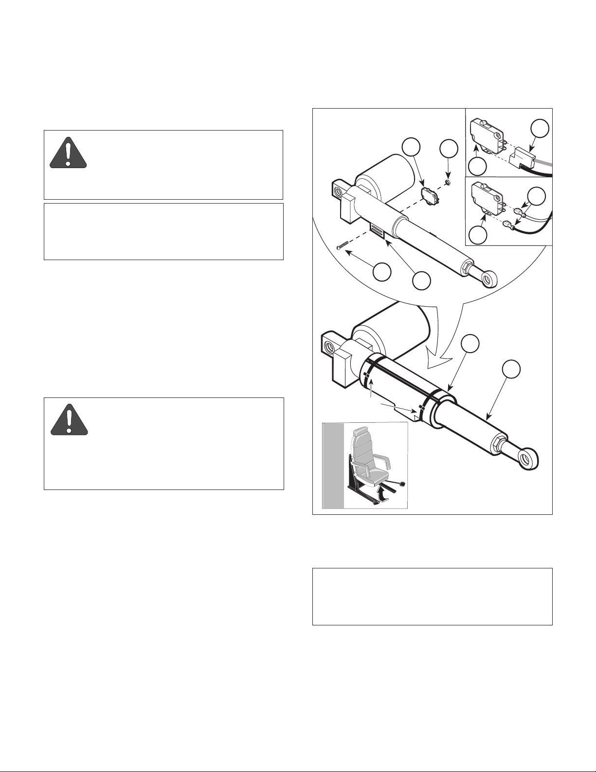
(3) Remove two cable ties and remove actuator
sleeve (1, Figure 4-2) from shaft of seat actuator (2).
(4) On early units, tag and disconnect two wires
(3A) from terminals of seat up limit switch (4).
On later units, disconnect wire harness (3B)
from seat up limit switch (4).
(5) Remove two screws (5), lockwashers (6), and
seat up limit switch assembly (4) from shaft of
seat actuator (2).
NOTE
Early units are units with Serial Numbers BK-1000
thru BK1271 and V-1000 thru V-1575. Later units
are units with Serial Numbers BK-1272, V-1576, and
FH-1000 thru Present.
(8) Cut any cable ties securing wire / wire har-
nesses to seat actuator (2).
(9) While supporting seat section (1, Figure 4-3),
remove two e-rings (2), clevis pin (3), and base
of seat actuator (4) from bracket (5).
(10) While supporting seat section (1), remove two
e-rings (6), spacers (7), clevis pin (8), and seat
actuator (4) from bracket (9). Remove seat
actuator from chair.
B. Installation
NOTE
This jam nut has left hand threads.
(1) Loosen jam nut (10, Figure 4-3); then remove
swivel joint (11) from shaft of new seat actuator (4).
(2) Coat threads of swivel joint (11) with permanent
threadlocking adhesive (Loctite 262).
(3) Screw swivel joint (11) into shaft of seat
actuator (4).
(4) While supporting seat section (1), install base
of seat actuator (4) on bracket (5) and secure
with clevis pin (3) and two e-rings (2).
(5) While supporting seat section (1), install shaft
end of seat actuator (4) on bracket (9) and
secure temporarily with clevis pin (8).
NOTE
The following step applies to later units only.
(6) On early units, tag and disconnect three wires
(7A) from three actuator wires (8A).
On later units, disconnect wire harness (7B)
from connector receptacle (8B).
© Midmark Corporation 1995 SF-1457 Page 4-2 Printed in U.S.A.
(6) On later units, install receptacle bracket (10,
Figure 4-2) on pivot frame (11) and secure with
two screws (9).
Page 21
10
Return To Table Of Contents
SECTION IV
MAINTENANCE / SERVICE
VIEW
7A
8A
8B
WIRING
HARNESS
7B
WIRING HARNESS
CABLE TIES
11
LATER
UNITS
4
9
3B
EARLY UNITS
6
5
3A
1
2
Figure 4-2. Seat Actuator Wires Disconnection / Connection
(7) On early units, connect three wires (7A) to
three actuator wires (8A).
On later units, connect wire harness (7B) to
connector receptacle (8B).
(8) Install switch bracket assembly (4) on shaft of
seat actuator (2) and secure with two
lockwashers (6) and screws (5).
(9) On early units, connect two wires (3A) to
terminals of seat up limit switch (4).
On later units, connect wire harness (3B) to
seat up limit switch (4).
(10) Secure wires / wire harnesses to seat actuator
(2) with a cable tie.
MA316700
(11) Install actuator sleeve (1) on shaft of seat
actuator (2) and secure with two cable ties.
(12) Run SEAT UP function all the way up and then
run TABLE DOWN function all the way down.
(13) If seat section (1, Figure 4-3)
go to step 18. If seat section (1)
with floor, go to step 14.
(14) While supporting seat section (1), remove
clevis pin (8) securing swivel joint (11) of seat
actuator (4) to bracket (9).
(15) Screw swivel joint (11) in or out as determined
necessary in step 13.
is
level with floor,
is not
level
© Midmark Corporation 1995 SF-1457 Page 4-3 Printed in U.S.A.
Page 22
SECTION IV
Return To Table Of Contents
MAINTENANCE / SERVICE
5
1
3
2
1
PARALLEL
SPACING
LEVEL WITH THE FLOOR
Figure 4-3. Seat Actuator Removal / Installation
(16) Connect swivel joint (11) of seat actuator (4) to
bracket (9) and secure with clevis pin (8).
(17) Repeat steps 12 thru 16 until seat section (1) is
level with floor.
(18) Install spacers (7) and two e-rings (6) on clevis
pin (8).
6
9
4
11
10
DANGER
Always disconnect the power cord
from the wall outlet before removing
any of the chair's covers/shrouds or making any
repairs to prevent the possibility of electrical
shock. Failure to comply with these instructions
could result in severe personal injury or death.
6
7
8
MA316800
(19) Tighten jam nut (10).
(20) Plug chair power cord into wall outlet.
4.4 Pan Safety Limit Switch Removal /
Installation
A. Removal
(1) If possible, run seat section all the way down.
© Midmark Corporation 1995 SF-1457 Page 4-4 Printed in U.S.A.
(2) Unplug chair power cord from wall outlet.
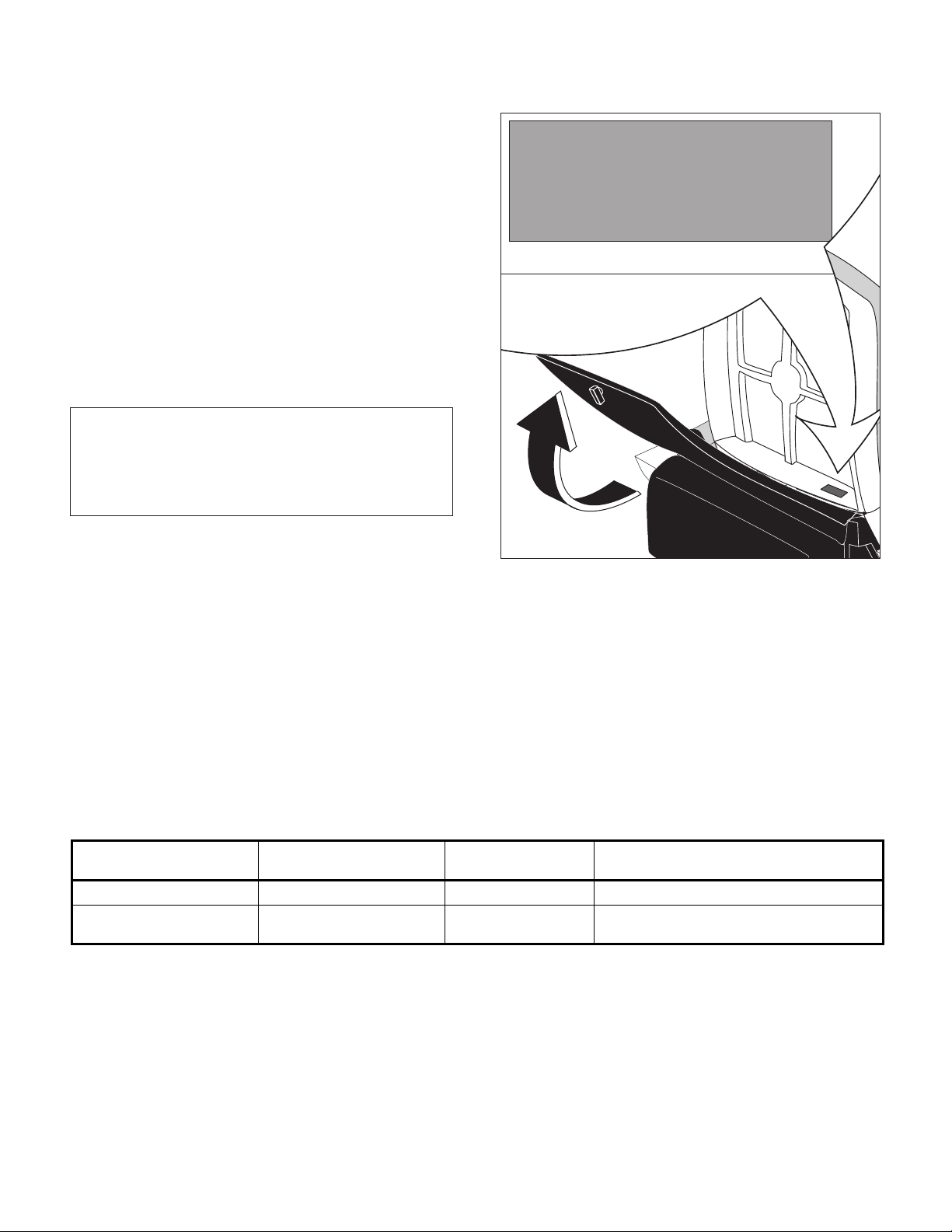
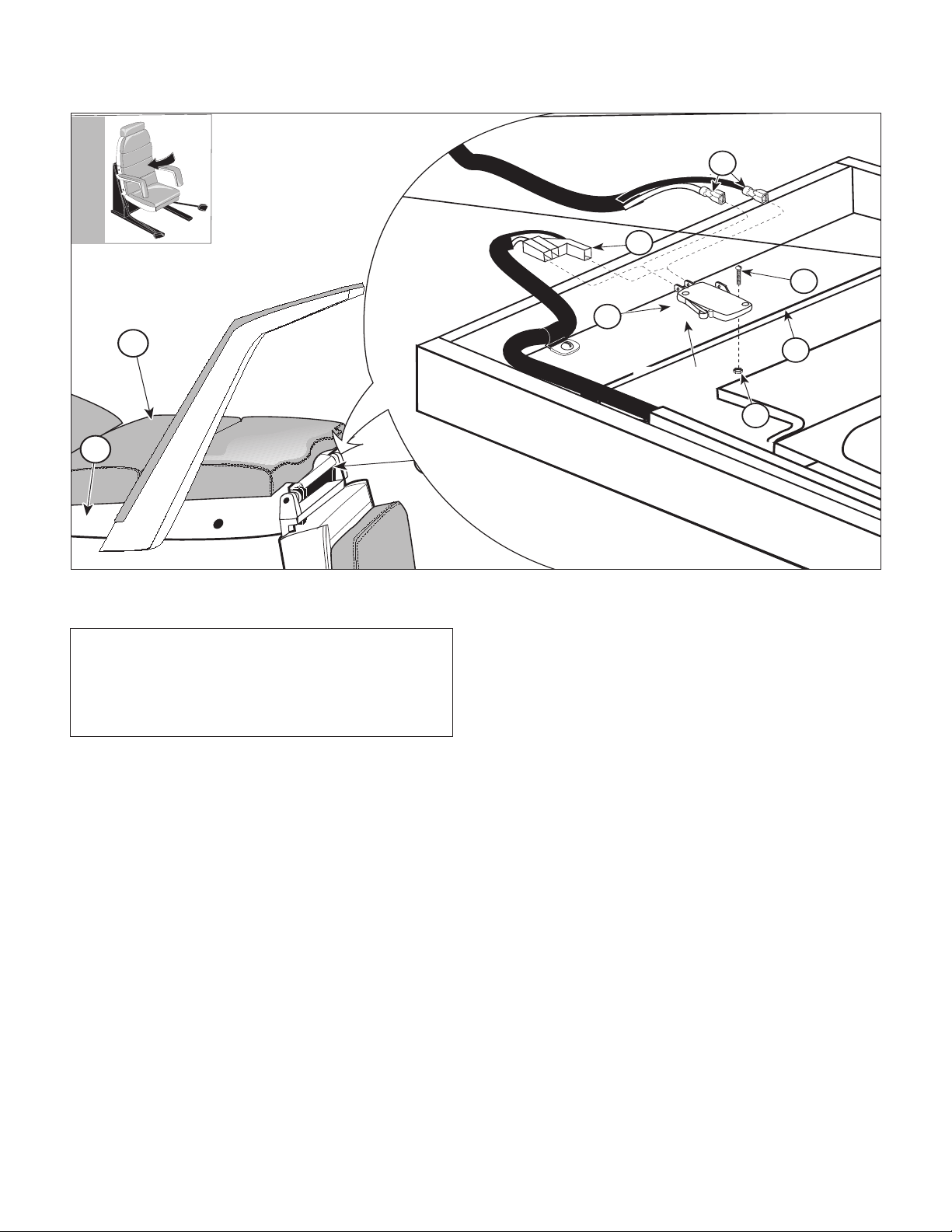
NOTE
The upholstered lower back section is held onto the
lower back casting with velcro.
(3) Remove upholstered lower back section (1,
Figure 4-4) from lower back casting (2).
(4) Pull pan holder assembly (3) out as far as
possible.
Page 23
VIEW
LATER UNITS
7
6
8
TRIP ARM
5
4A
EARLY UNITS
MA316900
4B
Return To Table Of Contents
1
SECTION IV
MAINTENANCE / SERVICE
2
Figure 4-4. Pan Safety Limit Switch Removal / Installation
NOTE
Early units are units with Serial Numbers BK-1000
thru BK1271 and V-1000 thru V-1575. Later units
are units with Serial Numbers BK-1272, V-1576, and
FH-1000 thru Present.
(5) On early units, tag and disconnect two wires
(4A) from pan safety limit switch (5).
On later units, disconnect wire harness (4B)
from pan safety limit switch (5).
(6) Remove two nuts (6), screws (7), and pan
safety limit switch (5) from pan frame (8).
B. Installation
3
(3) Push pan holder assembly (3) all the way in
until it locks into its fully stowed position, while
observing, from under lower back casting (2),
how the pan safety limit switch (5) is being
tripped.
(4) Slide pan safety limit switch (5) inward or
outward as determined necessary, so that the
trip arm of pan safety limit switch is tripped just
before the pan holder assembly (3) locks into
its fully stowed position.
(5) Repeat steps 3 and 4 until the pan safety limit
switch (5) is positioned properly. Then secure
the pan safety limit switch (5) in position by
tightening two nuts (6).
(1) Install pan safety limit switch (5) on pan frame
(8) and secure with two screws (7) and nuts
(6). Do not tighten nuts at this time.
(2) On early units, connect one wire (4A) to N.O.
terminal and other wire (4A) to COM. terminal
of pan safety limit switch (5).
On later units, connect wire harness (4B) to
pan safety limit switch (5).
© Midmark Corporation 1995 SF-1457 Page 4-5 Printed in U.S.A.
(6) Install upholstered lower back section (1) on
lower back casting (2).
(7) Plug chair power cord into wall outlet.
Page 24
SECTION IV
6
5
7
8
Return To Table Of Contents
MAINTENANCE / SERVICE
4.5 Gas Spring Removal / Installation
A. Removal
(1) If possible, raise TABLE UP and SEAT UP
functions all the way up.
WARNING
Always disconnect the power cord
from the wall outlet before removing
any of the table's covers / shrouds or making any
repairs to prevent the possibility of electrical
shock. Failure to comply with these instructions
could result in severe personal injury or death.
(2) Unplug chair power cord from wall outlet.
1
3
(3) Remove seven screws (1, Figure 4-5), outer
shroud (2), and inner shroud (3) from base
casting (4).
WARNING
If TABLE UP function is not all the way
up, the gas spring will be under extreme pressure. Raise table all the way up before
removing gas spring mounting hardware. Failure
to do so could result in serious personal injury
or death.
(4) Remove two screws (5), four washers (6), and
gas spring (7) from brackets (8).
B. Installation
(1) Coat threads of two screws (5) with removable
threadlocking adhesive (Loctite 242).
(2) Install gas spring (7) on brackets (8) and
secure with four washers (6) and two
screws (5).
2
4
7
8
6
6
5
(3) Install inner shroud (3) and outer shroud (2) on
base casting (4) and secure with seven
screws (1).
(4) Plug chair power cord into wall outlet.
© Midmark Corporation 1995 SF-1457 Page 4-6 Printed in U.S.A.
MA317000
Figure 4-5. Gas Spring Removal / Installation
Page 25
4.6 Base Actuator Removal / Installation
11
13
1
2
5
6
7
8
9
10
11
4
3
12
11
Return To Table Of Contents
A. Removal
SECTION IV
MAINTENANCE / SERVICE
7
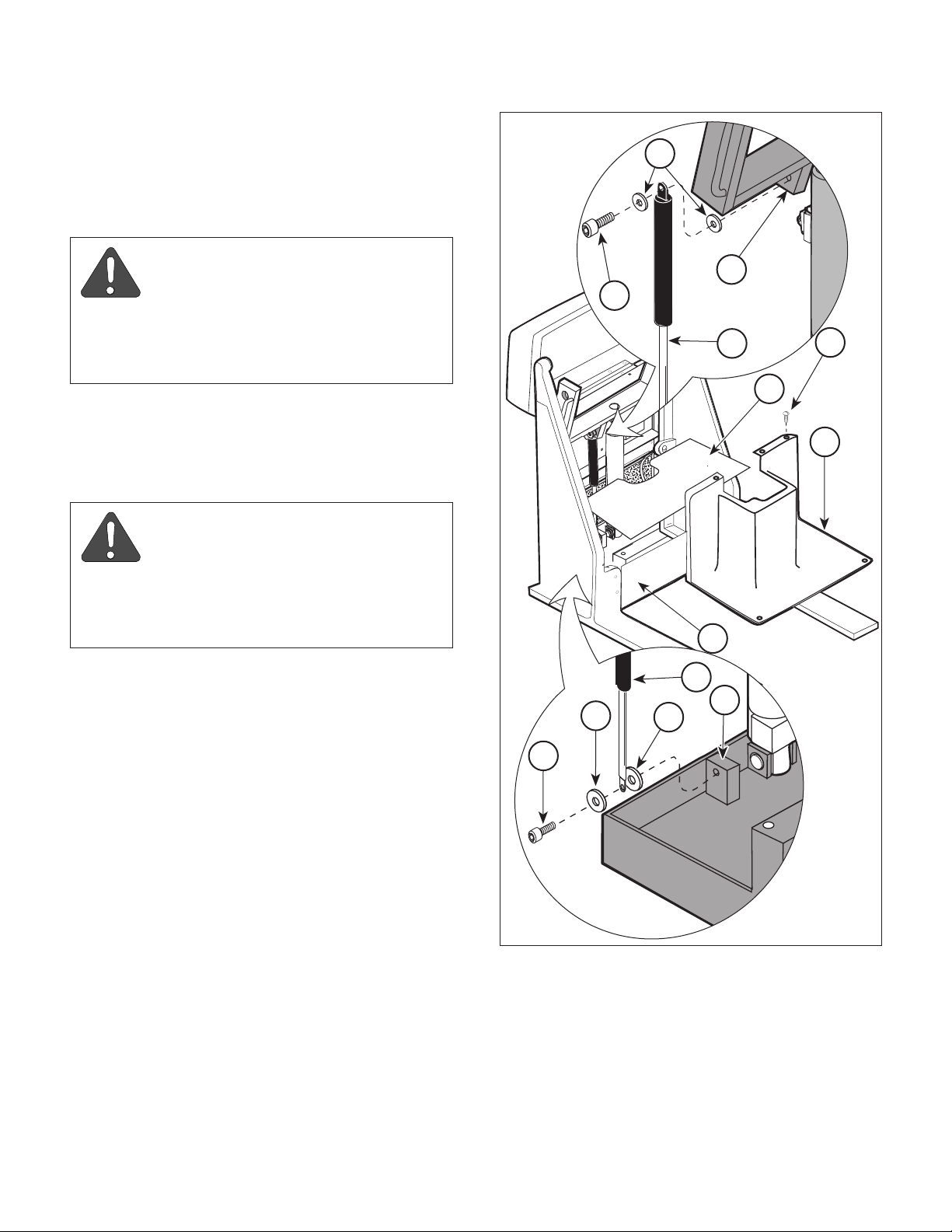
(1) Remove gas spring (Refer to para 4.5).
(2) Remove stirrup from patient's right side of
chair.
WARNING
Chair is heavy. Use proper lifting
techniques (and an assistant if necessary) to raise and lower chair. Failure to do so
could result in back injury.
(3) Lay chair onto its right side (patients).
(4) Remove two screws (1, Figure 4-6) and gas
spring base mounting bracket (2) from base
casting (3).
(5) Remove two screws (4), lockwashers (5), and
switch bracket assembly (6) from shaft of base
actuator (7).
(6) Cut cable ties securing wires to base actu-
ator (7).
6
4
5
CABLE
TIES
2
8
10
9
3
1
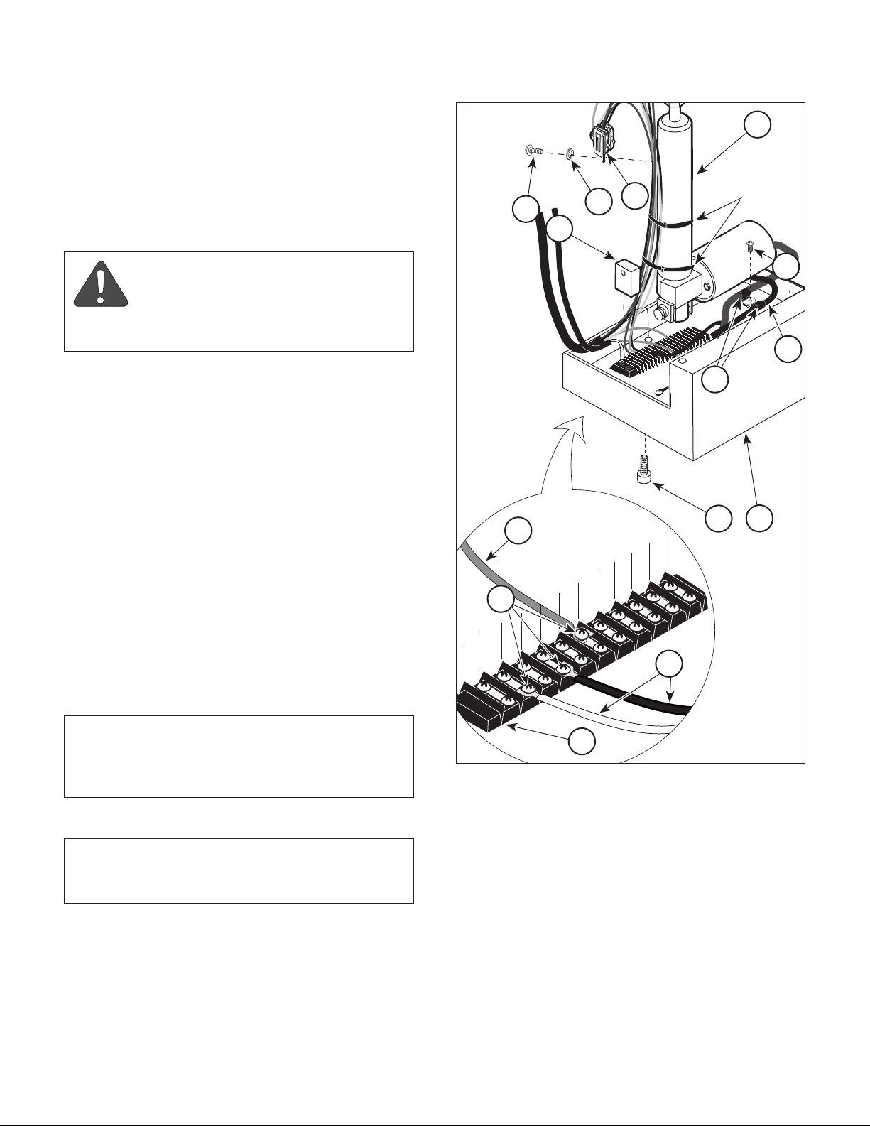
(7) Remove screw (8) and two cable clamps (9)
from base casting (3). Remove cable clamp (9)
off of base actuator cable (10).
(8) Tag three actuator wires (11); then loosen three
terminal screws (12) and disconnect three
actuator wires (11) from terminal block (13).
NOTE
Access to jam nut (1) may only be possible with a
"homemade" ground down 1-1/8 in. open end
wrench.
(9) Loosen jam nut (1, Figure 4-7).
NOTE
Setscrews are only on later units. Open rear access
door to gain access to the rear setscrew.
(10) If present, loosen two setscrews (2).
Figure 4-6. Wires Disconnection / Connection
(11) Remove screw (3), six screws (4), and back
cover (5) from side uprights (6).
(12) While supporting seat section (7), remove two
e-rings (8) and clevis pin (9) securing base of
base actuator (10) to bracket (11).
MA317100
© Midmark Corporation 1995 SF-1457 Page 4-7 Printed in U.S.A.
Page 26

SECTION IV
Return To Table Of Contents
MAINTENANCE / SERVICE
13
7
6
4
P ARALLEL
SPACING
REAR ACCESS
DOOR
3
9
5
2
12
SHAFT
1
10
6
11
8
MA317200
Figure 4-7. Base Actuator Removal / Installation
NOTE
Note how far threads of base actuator are screwed
into chair yoke frame.
(13) While supporting seat section (7), use strap
wrench or channel lock pliers with a soft cloth
to unscrew shaft of base actuator (10) from
chair yoke frame (12).
B. Installation
(1) Screw jam nut (1, Figure 4-7) onto threads of
base actuator (10) fully.
(2) If unit does not have two setscrews (2), apply
permanent threadlocking adhesive (Loctite 262)
to threads of base actuator (10).
(3) While supporting seat section (7), screw new
base actuator (10) into chair yoke frame (12)
approximately the same distance as old base
actuator used to be.
(4) While supporting seat section (7), connect base
actuator (10) to bracket (11) with clevis pin (9)
and two e-rings (8).
(5) Connect three actuator wires (11, Figure 4-6) to
terminal block (13) and secure by tightening
three terminal screws (12).
(6) Install one cable clamp (9) onto base actuator
cable (10); then secure both cable clamps (9)
to base casting (3) with screw (8).
(7) Install switch bracket (6) on shaft of base
actuator (7) and secure with two lockwashers
(5) and screws (4).
(8) Secure wires to base actuator (7) with three
cable ties.
(9) Raise chair to upright position.
© Midmark Corporation 1995 SF-1457 Page 4-8 Printed in U.S.A.
Page 27
SECTION IV
Return To Table Of Contents
MAINTENANCE / SERVICE
(10) Plug chair power cord into wall outlet.
(11) Run SEAT UP function all the way up and
TABLE DOWN function all the way down.
(12) If lower back casting (13, Figure 4-7)
with angled surface of side upright (6), go to
step 16.
If lower back casting (13)
angled surface of side upright (6), go to
step 13.
(13) Using strap wrench or channel lock pliers with a
soft cloth, screw shaft of base actuator (10) in
or out of chair yoke frame (12) as determined
necessary in step 12.
(14) Repeat steps 11 thru 13 until lower back
casting (13)
side upright (6) when chair is in full TABLE
DOWN position.
(15) Tighten jam nut (1).
is
parallel with angled surface of
is not
is
parallel
parallel with
NOTE
Setscrews are only on later units. Open rear access
door to gain access to the rear setscrew.
4.7 Typical Capacitor Removal / Installation
A. Removal
(1) If possible, raise TABLE UP and SEAT UP
function all the way up.
WARNING
Always disconnect the power cord
from the wall outlet before removing
any of the table's covers / shrouds or making any
repairs to prevent the possibility of electrical
shock. Failure to comply with these instructions
could result in severe personal injury or death.
(2) Unplug chair power cord from wall outlet.
(3) Remove seven screws (1, Figure 4-8), outer
shroud (2), and inner shroud (3) from base
casting (4).
(4) Using a screwdriver, pry tab of capacitor
mounting bracket (5) outward and remove
capacitor (6) from capacitor mounting bracket.
(5) Remove capacitor cap (7) from capacitor (6).
(16) If present, tighten two setscrews (2).
(17) Install back cover (5) on side uprights (6) and
secure with six screws (4) and one screw (3).
WARNING
Chair is heavy. Use proper lifting
techniques (and an assistant if necessary) to raise and lower chair. Failure to do so
could result in back injury.
(18) Lay chair onto its side.
(19) Install gas spring base mounting bracket (2,
Figure 4-6) on base casting (3) and secure with
two screws (1).
(20) Raise chair to upright position.
(21) Install gas spring (Refer to para 4.5).
(22) Install stirrup.
WARNING
A capacitor contains stored electricity.
Never touch terminals of a capacitor,
even if power has been shut off or disconnected.
Always discharge capacitor before touching
capacitor terminals or wires. Failure to comply
with these instruction could result in serious
personal injury or death.
(6) Discharge capacitor (6).
(7) Disconnect two wires (8) from terminals of
capacitor (6).
B. Installation
(1) Connect two wires (8) to terminals of capaci-
tor (6).
(2) Install capacitor cap (7) on capacitor (6).
© Midmark Corporation 1995 SF-1457 Page 4-9 Printed in U.S.A.
Page 28

SECTION IV
SEAT
CAPACITOR
7
5
6
8
BASE
CAPACITOR
CATCH
TAB
1
2
3
4
VIEW
MA317300
Return To Table Of Contents
MAINTENANCE / SERVICE
(3) Position bottom of capacitor (6) on capacitor
mounting bracket (5) and then push the top of
the capacitor in. Using a screwdriver, force tab
of capacitor mounting bracket (5) down over
catch.
(4) Install inner shroud (3) and outer shroud (2) on
base casting (4) and secure with seven
screws (1).
(5) Plug chair power cord into wall outlet.
4.8 Typical Actuator Motor / Actuator
Brake Removal / Installation
A. Removal
(1) Remove malfunctioning actuator assembly:
Seat actuator assembly (Refer to para 4.3).
Base actuator assembly (Refer to para 4.6).
Figure 4-8. Typical Capacitor Removal / Installation
(2) Remove two nuts (1, Figure 4-9) and actuator
motor (2) from actuator mechanism (3).
(3) Remove two shoulder washers (4) from actua-
tor mechanism (3).
(4) Remove spacer (5) and motor coupler (6) from
shaft of actuator motor (2).
NOTE
A needle nose pliers should be used to extract the
actuator brake from the actuator mechanism. Grasp
the raised round plate of the actuator brake with the
pliers and pull.
(5) Remove actuator brake (7) and rubber damper
(8) from shaft of actuator mechanism (3).
B. Installation
NOTE
The rubber damper must be installed so its flat side
faces the inside of the actuator mechanism. The
actuator brake must be installed so its flattest side
faces outward. The shaft of the actuator mechanism
may be turned with a screwdriver to help align the
keys of the actuator mechanism shaft with the key
slots in actuator brake.
© Midmark Corporation 1995 SF-1457 Page 4-10 Printed in U.S.A.
Page 29

SECTION IV
Return To Table Of Contents
MAINTENANCE / SERVICE
(6) Check actuator assembly for proper operation.
The actuator assembly should run normally and
should not make a grinding noise. A grinding
noise indicates that key slots of motor coupler
1
4
were not aligned properly with keys of actuator
mechanism (a grinding noise also indicates that
the motor coupler is being damaged). The
actuator assembly should brake properly.
4.9 Base Down Limit Switch or Seat Down
KEYS
7
Limit Switch Removal / Installation
6
3
KEY SLOTS
8
KEY
7
SLOT
Figure 4-9. Typical Actuator Motor / Actuator Brake
Removal / Installation
(1) Install rubber damper (8), actuator brake (7),
and spacer (5) in actuator mechanism (3).
(2) Install motor coupler (6) on shaft of actuator
motor (2).
5
2
MA317400
A. Removal
(1) If possible, raise TABLE UP and SEAT UP
functions all the way up.
WARNING
Always disconnect the power cord
from the wall outlet before removing
any of the table's covers / shrouds or making any
repairs to prevent the possibility of electrical
shock. Failure to comply with these instructions
could result in severe personal injury or death.
(2) Unplug chair power cord from wall outlet.
(3) Remove seven screws (1, Figure 4-10), outer
shroud (2), and inner shroud (3) from base
casting (4).
(4) Remove two screws (5), lockwashers (6), and
switch bracket (7) from shaft of base actuator (8).
(5) Tag and disconnect two wires (1, Figure 4-11)
from base down limit switch (2).
(3) Install two shoulder washers (4) in actuator
mechanism (3).
(4) Align keys of actuator mechanism (3) shaft with
key slots of motor coupler (6) and then install
actuator motor (2) on actuator mechanism (3)
and secure with two nuts (1).
(5) Install actuator assembly:
Base actuator assembly (Refer to para 4.6).
Seat actuator assembly (Refer to para 4.3).
© Midmark Corporation 1995 SF-1457 Page 4-11 Printed in U.S.A.
(6) Tag and disconnect two wires (3) from seat
down limit switch (4).
NOTE
Note or mark the approximate position of the limit
switches on the switch bracket. This will help during
installation.
(7) Remove two nuts (5), lockwashers (6), screws
(7), and limit switches (2 and 4) from switch
bracket (8).
Page 30

SECTION IV
MA317500
1
2
3
VIEW
4
7
6
5
8
Return To Table Of Contents
MAINTENANCE / SERVICE
3
7
6
6
5
Figure 4-11. Wires Disconnection / Connection
1
4
2
8
MA317600
(2) Connect one wire (3) to N.C. terminal and the
other wire (3) to COM. terminal of seat down
limit switch (4).
(3) Connect one wire (1) to N.C. terminal and the
other wire (1) to COM. terminal of base down
limit switch (2).
(4) Install switch bracket (7, Figure 4-10) on shaft
of base actuator (8) and secure with two
lockwashers (6) and screws (5).
Figure 4-10. Base Down Limit Switch or
Seat Down Limit Switch Removal / Installation
B. Installation
(1) Install limit switches (2 and 4, Figure 4-11) on
switch bracket (8) and secure with two screws
(7), lockwashers (6), and nuts (5), making sure
to position the limit switches in approximately
same position as they were removed.
© Midmark Corporation 1995 SF-1457 Rev. 2/99 Page 4-12 Printed in U.S.A.
(5) Install inner shroud (3) and outer shroud (2) on
base casting (4) and secure with seven
screws (1).
(6) Plug chair power cord into wall outlet.
NOTE
The trip arms of the limit switches should be tripped
when the base up function is at 2/3 of it total height.
Page 31

(7) Run TABLE UP function up until the table top is
Return To Table Of Contents
at 2/3 of its total height.
(8) If limit switches trip too early, loosen two
screws (7, Figure 4-11) and slide limit switches
(2 and 4) downward slightly; then tighten two
screws (7).
SECTION IV
MAINTENANCE / SERVICE
3
RETURN
RETURN
If limit switches trip too late, loosen two screws
(7) and slide limit switches (2 and 4) upward
slightly; then tighten two screws (7).
(9) Repeat steps 7 and 8 until limit switches are
adjusted so they trip when table top reaches 2/
3 of its total height.
4.10 Typical Foot Pedal Footswitch Removal / Installation
A. Removal
WARNING
Always disconnect the power cord
from the wall outlet before removing
any of the table's covers / shrouds or making any
repairs to prevent the possibility of electrical
shock. Failure to comply with these instructions
could result in severe personal injury or death.
(1) Unplug chair power cord from wall outlet.
(2) Remove screw (1, Figure 4-12), lockwasher
(2), and pedal (3) from foot switch bracket (4).
AQUIRE
6
AQUIRE
2
5
9
8
1
7
PIVOT
SPACER
10
4
MA317701
(3) Remove two locknuts (5), screws (6), two
insulators (7), and footswitch (8) from
footswitch bracket (4).
(4) Tag and disconnect two
terminals of footswitch (8). Remove footswitch.
B. Installation
(1) Connect two
footswitch (8).
(2) Install footswitch (8) on foot switch bracket (4)
and secure with two insulators (7), screws (6),
and locknuts (5).
© Midmark Corporation 1995 SF-1457 Rev. 2/99 Page 4-13 Printed in U.S.A.
or
three wires (9) to terminals of
or
Figure 4-12. Typical Foot Pedal Footswitch
Removal / Installation
(3) Ensure springs (10) are in position and have
not fallen off.
three wires (9) from
(4) Install pedal (3) on foot switch bracket (4) and
secure with lockwasher (2) and screw (1),
making sure pedal is mounted on pivot spacer.
(5) Plug chair power cord into wall outlet.
Page 32

SECTION IV
Return To Table Of Contents
MAINTENANCE / SERVICE
© Midmark Corporation 1995 SF-1457 Page 4-14 Printed in U.S.A.
Page 33

SCHEMATICS AND DIAGRAMS
Return To Table Of Contents
SECTION V
SCHEMATICS AND DIAGRAMS
SECTION V
5.1 Electrical Schematics / Wiring
Diagrams
Figures 5-1 and 5-2 illustrate the wiring connections
RECEPTACLE WIRING
HARNESS 015-0431-00
BASE
CAPACITOR
(41-53 MFD)
ELECTRICAL
RECECTACLE
2 AMPS. MAX.
BLACK
BLACK
BLACK
BLACK
BLACK
(DOWN)
WHITE
BASE
ACTUATOR
FOOT PEDAL
WHITE
ORANGE
RED
BLUE
GREEN
BLACK
RED (UP)
SEAT UP
BASE
DOWN
BASE UP
SEAT DOWN
ORANGE
SEAT DOWN LIMIT SWITCHES, (N.C.)
(BASE FUNCTION- ALL THE WAY DOWN
TO 2/3 WAY UP = TRIPPED = OPEN
CIRCUIT
ORANGE
BLACK
BASE DOWN LIMIT SWITCHES, (N.C.)
(BASE FUNCTION- ALL THE WAY DOWN
TO 2/3 WAY UP = TRIPPED = OPEN
CIRCUIT
SEAT FUNCTION ALL THE WAY
UP= UNTRIPPED=CLOSED CIRCUIT,
ANY OTHER POSITION=TRIPPED=OPEN CIRCUIT
Figure 5-1 Wiring Diagam (Used on Domestic Units with
Serial Numbers: BK1000 Thru BK1271)
BLACK
ORANGE
RED
BLUE
WHITE
SEAT
CAPACITOR
(41-53 MFD)
GREEN
between the electrical components in the chair. Figures
5-3 and 5-4 illustrate the logic/current flow between the
electrical components in the chair.
GREEN/YELLOW
WHITE
1
WHITE
2
BLACK
3
BLACK
4
WHITE/BLACK
5
RED
6
BLUE
7
RED
8
ORANGE
9
10
11
BLUE
WHITE/BLACK
WHITE/BLACK
SEAT
ACTUATOR
SEAT LIMIT SWITCH, N.C.
ON SEAT ACTUATOR
WHITE/BLACK
BLACK
WHITE/BLACK
BLACK
ORANGE
RED (UP)
WHITE
BLACK (DOWN)
WHITE
GREEN
BLACK
PAN SAFETY
LIMIT SWITCH, (N.O.)
(PAN IN = CLOSED
CIRCUIT)
RED
WIRING HARNESS
015-0426-00
WHITE
RED
RED
WHITE
ORANGE
MA 307403
(Applies To 115 VAC Domestic Units With Serial Numbers BK-1000 Thru BK-1271
© Midmark Corporation 1995 SF-1457 Rev. 8/96 Page 5-1 Printed in U.S.A.
Figure 5-1 (Sheet 1 of 2). Wiring Diagram
Page 34

SECTION V
Return To Table Of Contents
SCHEMATICS AND DIAGRAMS
ELECTRICAL
RECEPTACLE
RECEPTACLE WIRING
HARNESS 015-0431-00
SEAT
CAPACITOR
(41-53 MFD)
BASE
CAPACITOR
(41-53 MFD)
2 AMPS. MAX.
GREEN/YELLOW
JUMPER WIRE
015-0022-00
POWER CORD
015-0066-02
120 V.A.C., 60 Hz.
6 AMPS..
JUMPER WIRE
015-0427-00
BLACK
ORANGE
RED
BLUE
WHITE
GREEN
BLACK
BLACK
BASE
ACTUATOR
FOOT CONTROL
WHITE
ORANGE
RED
BLUE
GREEN
BLACK
BLACK
BLACK
BLACK
(DOWN)
WHITE
RED (UP)
SEAT UP
BASE
DOWN
BASE UP
SEAT DOWN
TERMINAL
BLOCK
BLACK
ORANGE
SEAT DOWN LIMIT SWITCH (N.C)
(BASE FUNCTION - ALLTHE WAY DOWN TO
2/ 3 WAY UP= TRIPPED = OPEN CIRCUIT)
ORANGE
BLACK
BASE DOWN LIMIT SWITCH (N.C.) (BASE
FUNCTION- ALL THE WAY DOWN TO 2/3
WAY UP = TRIPPED = OPEN CIRCUIT)
BLACK
SEAT FUNCTION ALL THE WAY
UP = UNTRIPPED = CLOSED CIRCUIT,
ANY OTHER POSTION = TRIPPED = OPEN CIRCUIT
WHITE
WHITE
SEAT
ACTUATOR
SEAT UP LIMIT SWITCH (N.C.)
ON SEAT ACTUATOR
WHITE
WHITE
1
WHITE
2
BLACK
3
BLACK
4
BLUE
5
RED
6
WHITE/BLACK
7
BLACK
8
ORANGE
9
RED
10
11
WHITE/BLACK
BLUE
BLUE
BLACK
BLACK (DOWN)
RED (UP)
WHITE
WHITE
GREEN
BLACK
PAN SAFETY LIMIT
SWITCH, (N.O.)
(PAN IN = CLOSED CIRCUIT)
WHITE
PAN LIMIT SWITCH
HARNESS
015-0561-00
JUMPER WIRE
015-0428-01
WIRING HARNESS
002-0484-00
WHITE
RED
BLUE
BLACK
ORANGE
RED
WHITE
ORANGE
BLACK
BLACK
WHITE
BLUE
SEAT LIMIT SWITCH HARNESS
015-0562-00
MA307400
(Applies To 115 VAC Domestic Units With Serial Numbers BK-1272 and FH-1000 Thru Present)
© Midmark Corporation 1995 SF-1457 Page 5-2 Printed in U.S.A.
Figure 5-1 (Sheet 2 of 2). Wiring Diagram
Page 35

SEAT
Return To Table Of Contents
CAPACITOR
(12.5 MFD)
BASE
CAPACITOR
(12.5 MFD)
SECTION V
SCHEMATICS AND DIAGRAMS
220 V.A.C., 50 Hz.
1.5 AMPS..
5 X 20 MM. 1.5 AMP.
SLO BLO FUSES
BLACK
ORANGE
RED
BLUE
WHITE
GREEN
BASE
ACTUAT OR
FOOT CONTROL
GREEN
BLACK
BLACK
WHITE
ORANGE
BLUE
RED
BLACK
BLACK
BLACK
BLACK
(DOWN)
WHITE
RED (UP)
SEAT UP
BASE
DOWN
BASE UP
SEAT DOWN
WHITE
1
WHITE
2
BLACK
3
BLACK
4
WHITE/BLACK
5
RED
6
BLUE
7
RED
8
ORANGE
9
10
11
WHITE
ORANGE
SEAT DOWN LIMIT SWITCHES, (N.C.)
(BASE FUNCTION- ALL THE WAY DOWN
TO 2/3 WAY UP = TRIPPED = OPEN
CIRCUIT
ORANGE
BLACK
BASE DOWN LIMIT SWITCHES, (N.C.)
(BASE FUNCTION- ALL THE WAY DOWN
TO 2/3 WAY UP = TRIPPED = OPEN
CIRCUIT
SEAT LIMIT SWITCH, N.C.
ON SEAT ACTUATOR
SEAT FUNCTION ALL THE WAY
UP= UNTRIPPED=CLOSED CIRCUIT,
ANY OTHER POSITION=TRIPPED=OPEN CIRCUIT
BLUE
WHITE/BLACK
WHITE/BLACK
SEAT
ACTUATOR
BLACK
BLACK (DOWN)
WHITE/BLACK
RED (UP)
WHITE
WHITE
GREEN
BLACK
PAN SAFETY
LIMIT SWITCH, (N.O.)
(PAN IN = CLOSED
CIRCUIT)
RED
WHITE
WHITE/BLACK
BLACK
ORANGE
RED
RED
WHITE
ORANGE
MA 307402
(Applies To 220 VAC Export Units With Serial Numbers V-1000 Thru V-1575)
© Midmark Corporation 1995 SF-1457 Page 5-3 Printed in U.S.A.
Figure 5-2 (Sheet 1 of 2). Wiring Diagram
Page 36

SECTION V
Return To Table Of Contents
SCHEMATICS AND DIAGRAMS
220 V.A.C., 50 Hz.
1.5 AMPS.
BLACK
ORANGE
RED
BLUE
WHITE
SEAT
CAPACITOR
(41-53 MFD)
BLACK
GREEN
BASE
ACTUATOR
BASE
CAPACITOR
(41-53 MFD)
BLACK
BLACK
BLACK
BLACK
(DOWN)
WHITE
RED (UP)
ORANGE
JUMPER WIRE
015-0305-02
WHITE
1
WHITE
2
BLACK
3
BLACK
4
BLUE
5
RED
6
WHITE/BLACK
7
BLACK
8
ORANGE
9
RED
10
11
WHITE
ORANGE
SEAT DOWN LIMIT SWITCH (N.C.)
(BASE FUNCTION - ALL THE WAY DOWN TO
2/3 WAY UP = TRIPPED = OPEN CIRCUIT)
WHITE/BLACK
5 X 20 MM. 1.5 AMP.
SLO BLO FUSES
JUMPER WIRE
015-0303-00
WHITE
GRN/YLW
BLACK
PAN SAFETY LIMIT SWITCH,(N.O.)
(PAN IN =CLOSED
CIRCUIT)
PAN LIMIT SWITCH HARNESS
015-0561-00
JUMPER WIRE
015-0305-03
WHITE
FOOT CONTROL
WHITE
ORANGE
RED
BLUE
GREEN
BLACK
Figure 5-2 Wiring Diagram (Used on Export Units with
Serial Numbers: V 1576 Thru Present)
BLACK
BASE DOWN LIMIT SWITCH (N.C.) (BASE
FUNCTION - ALL THE WAY DOWN TO 2/3
WAY UP = TRIPPED = OPEN CIRCUIT)
BLACK
SEAT UP
BASE
DOWN
BASE UP
SEAT LIMIT SWITCH, (N.C.)
ON SEAT ACTUATOR
SEAT DOWN
SEAT FUNCTION ALL THE WAY
UP= UNTRIPPED=CLOSED CIRCUIT,
ANY OTHER POSITION=TRIPPED=OPEN CIRCUIT
BLUE
BLUE
SEAT
ACTUATOR
WHITE
BLACK
RED (UP)
WHITE
BLACK (DOWN)
BLACK
WHITE
SEAT LIMIT SWITCH HARNESS
015-0562-00
WHITE
RED
BLUE
BLACK
ORANGE
RED
WHITE
ORANGE
BLACK
BLUE
WIRING HARNESS
002-0484-00
MA 307401
(Applies To 220 VAC Export Units With Serial Numbers V-1576 Thru Present)
© Midmark Corporation 1995 SF-1457 Rev 7/98 Page 5-4 Printed in U.S.A.
Figure 5-2 (Sheet 2 of 2). Wiring Diagram
Page 37

SCHEMATICS AND DIAGRAMS
Return To Table Of Contents
Positions:
- Pan Switch - CLOSED
- Seat Down Switch- OPEN
- Base Down Switch - OPEN
- Seat Up Switch - CLOSED
Conclusions:
- Base can power either direction.
- Seat can power up only!
ELECTRICAL
RECEPTACLE
SECTION V
WHITE
SEAT
ACTUATOR
BLACK
BASE
ACTUATOR
WHITE
RED
SEAT
CAPACITOR
SEAT UP
LIMIT SWITCH
(N.C.)
BLACK
BASE
RED
CAPACITOR
PAN SAFETY LIMIT SWITCH
WHITE
BLACK
WHITE
ORANGE
BLACK
BLACK
BLACK
SEAT DOWN
LIMIT SWITCH
(N.C.)
BASE DOWN
LIMIT SWITCH
(N.C.)
BLUE
GRN/YLW
WHT/BLK
WHITE
ORANGE
RED
BLUE
BLACK
SEAT UP
BASE
DOWN
BASE UP
SEAT DOWN
FOOT CONTROL
WHITE
BLACK
GREEN
WHITE
Figure 5-3. Electrical Schematic (Applies To 115 VAC Domestic Units)
© Midmark Corporation 1995 SF-1457 Rev. 5/00 Page 5-5 Printed in U.S.A.
MA318101
Page 38

SECTION V
Return To Table Of Contents
SCHEMATICS AND DIAGRAMS
Positions:
- Pan Switch - CLOSED
- Seat Down Switch- CLOSED
- Base Down Switch - CLOSED
- Seat Up Switch - CLOSED
Conclusions:
- Base can power both up and down.
- Seat can power both up and down.
ELECTRICAL
RECEPTACLE
WHITE
SEAT
ACTUATOR
BLACK
BASE
ACTUATOR
WHITE
RED
SEAT
CAPACITOR
SEAT UP
LIMIT SWITCH
(N.C.)
BLACK
BASE
RED
CAPACITOR
PAN SAFETY LIMIT SWITCH
WHITE
BLACK
WHITE
ORANGE
BLACK
BLACK
BLACK
SEAT DOWN
LIMIT SWITCH
(N.C.)
BASE DOWN
LIMIT SWITCH
(N.C.)
BLUE
GRN/YLW
WHT/BLK
WHITE
ORANGE
RED
BLUE
BLACK
SEAT UP
BASE
DOWN
BASE UP
SEAT DOWN
FOOT CONTROL
WHITE
BLACK
GREEN
WHITE
Figure 5-3. Electrical Schematic (Applies To 115 VAC Domestic Units)
© Midmark Corporation 1995 SF-1457 Rev. 5/00 Page 5-6 Printed in U.S.A.
MA318102
Page 39

SCHEMATICS AND DIAGRAMS
Return To Table Of Contents
Positions:
- Pan Switch - CLOSED
- Seat Down Switch- CLOSED
- Base Down Switch - CLOSED
- Seat Up Switch - OPEN
Conclusions:
- Base can go down only until limit
switches are contacted (2/3).
- Seat can go either direction.
SECTION V
SEAT
ACTUATOR
BLACK
BASE
ACTUATOR
WHITE
RED
SEAT
CAPACITOR
SEAT UP
LIMIT SWITCH
(N.C.)
BLACK
BASE
RED
CAPACITOR
PAN SAFETY LIMIT SWITCH
WHITE
BLACK
WHITE
ORANGE
BLACK
BLACK
BLACK
SEAT DOWN
LIMIT SWITCH
(N.C.)
BASE DOWN
LIMIT SWITCH
(N.C.)
BLUE
GRN/YLW
WHT/BLK
ELECTRICAL
RECEPTACLE
WHITE
ORANGE
RED
BLUE
WHITE
BLACK
SEAT UP
BASE
DOWN
BASE UP
SEAT DOWN
FOOT CONTROL
WHITE
BLACK
GREEN
WHITE
Figure 5-3. Electrical Schematic (Applies To 115 VAC Domestic Units)
© Midmark Corporation 1995 SF-1457 Page 5-7 Printed in U.S.A.
MA318103
Page 40

SECTION V
Return To Table Of Contents
SCHEMATICS AND DIAGRAMS
Positions:
- Pan Switch - CLOSED
- Seat Down Switch- OPEN
- Base Down Switch - OPEN
- Seat Up Switch - CLOSED
Conclusions:
- Base can power either direction.
- Seat can power up only!
SEAT
ACTUATOR
BLACK
BASE
ACTUATOR
WHITE
RED
SEAT
CAPACITOR
SEAT UP
LIMIT SWITCH
(N.C.)
BLACK
BASE
RED
CAPACITOR
PAN SAFETY LIMIT SWITCH
WHITE
BLACK
WHITE
ORANGE
BLACK
BLACK
BLACK
SEAT DOWN
LIMIT SWITCH
(N.C.)
BASE DOWN
LIMIT SWITCH
(N.C.)
BLUE
WHT/BLK
WHITE
ORANGE
RED
BLUE
SEAT UP
BASE
DOWN
BASE UP
SEAT DOWN
FOOT CONTROL
WHITE
BLACK
GRN/YLW
WHITE
Figure 5-4. Electrical Schematic (Applies To 220 VAC Export Units)
© Midmark Corporation 1995 SF-1457 Page 5-8 Printed in U.S.A.
MA318201
Page 41

Positions:
Return To Table Of Contents
- Pan Switch - CLOSED
- Seat Down Switch- CLOSED
- Base Down Switch - CLOSED
- Seat Up Switch - CLOSED
Conclusions:
- Base can power both up and down.
- Seat can power both up and down.
SECTION V
SCHEMATICS AND DIAGRAMS
SEAT
ACTUATOR
BLACK
BASE
ACTUATOR
WHITE
RED
SEAT
CAPACITOR
SEAT UP
LIMIT SWITCH
(N.C.)
BLACK
BASE
RED
CAPACITOR
PAN SAFETY LIMIT SWITCH
WHITE
BLACK
WHITE
ORANGE
BLACK
BLACK
BLACK
SEAT DOWN
LIMIT SWITCH
(N.C.)
BASE DOWN
LIMIT SWITCH
(N.C.)
BLUE
WHT/BLK
WHITE
ORANGE
RED
BLUE
SEAT UP
BASE
DOWN
BASE UP
SEAT DOWN
FOOT CONTROL
WHITE
BLACK
GRN/YLW
WHITE
Figure 5-4. Electrical Schematic (Applies To 220 VAC Export Units)
© Midmark Corporation 1995 SF-1457 Page 5-9 Printed in U.S.A.
MA318202
Page 42

SECTION V
Return To Table Of Contents
SCHEMATICS AND DIAGRAMS
Positions:
- Pan Switch - CLOSED
- Seat Down Switch- CLOSED
- Base Down Switch - CLOSED
- Seat Up Switch - OPEN
Conclusions:
- Base can go down only until limit
switches are contacted (2/3).
- Seat can go either direction.
SEAT
ACTUATOR
BLACK
BASE
ACTUATOR
WHITE
RED
SEAT
CAPACITOR
SEAT UP
LIMIT SWITCH
(N.C.)
BLACK
BASE
RED
CAPACITOR
PAN SAFETY LIMIT SWITCH
WHITE
BLACK
WHITE
ORANGE
BLACK
BLACK
BLACK
SEAT DOWN
LIMIT SWITCH
(N.C.)
BASE DOWN
LIMIT SWITCH
(N.C.)
BLUE
WHT/BLK
WHITE
ORANGE
RED
BLUE
SEAT UP
BASE
DOWN
BASE UP
SEAT DOWN
FOOT CONTROL
WHITE
BLACK
GRN/YLW
WHITE
Figure 5-4. Electrical Schematic (Applies To 220 VAC Export Units)
© Midmark Corporation 1995 SF-1457 Page 5-10 Printed in U.S.A.
MA318203
Page 43

SECTION VI
Return To Table Of Contents
P ARTS LIST
6.1 Introduction
The illustrated parts list provides information for identifying and ordering the parts necessary to maintain the
unit in peak operating condition. Refer to paragraph 1.5
for parts ordering information.
The parts list also illustrates disassembly and assembly
relationships of parts.
6.2 Description of Columns
The
Item
column of the parts list gives a component its
own unique number. The same number is given to the
component in the parts illustration. This allows a part
number of a component to be found if the technician
can visually spot the part on the illustration. The
technician simply finds the component in question on
the illustration and notes the item number of that
component. Then, he finds that item number in the
parts list. The row corresponding to the item number
gives the technician the part number, a description of
the component, and quantity of parts per subassembly.
Also, if a part number is known, the location of that
component can be determined by looking for the item
number of the component on the illustration.
The
Part No.
for that component.
column lists the MIDMARK part number
SECTION VI
PARTS LIST
The
Description
of the component.
The
Qty.
component that is required for the subassembly. The
letters “AR” denote “as required” when quantities of a
particular component cannot be determined, such as:
adhesive.
Bullets [ • ] in the
column show the indenture level of a component. If a
component does not have a bullet, it is a main component of that illustration. If a component has a bullet, it is
a subcomponent of the next component listed higher in
the parts list than itself that does not have a bullet.
Likewise, if a component has two bullets, it is a subcomponent of the next component listed higher in the
parts list than itself that has only one bullet.
column provides a physical description
column lists the number of units of a particular
Part No.
column and the
Description
6.3 Torque Specifications and Important
Assembly Notes
When specific assembly torque specifications, measurements, or procedures have been identified, by our
engineering department, as required to assure proper
function of the unit, those torque specifications measurements, and procedures will be noted on the parts
illustrations. Adherence to these requirements is
essential.
© Midmark Corporation 1995 SF-1457 Page 6-1 Printed in U.S.A.
Page 44

Pictorial Index
Return To Table Of Contents
1
SECTION VI
PARTS LIST
16
10
17
13
20
14
2
1
4
1
5
2
9
2
1
3
7
6
8
12
17
19
16
18
2
5
1
11
16
8
Item Part No. Description Page
413 Lithotomy Table
1 • • Labels and Decals ........................... 6-4
2 • • Upholstery ........................................ 6-5
3 • • Main Frame ...................................... 6-6
4 • • Armrest Assembly ............................ 6-7
5 • • Cross Support .................................. 6-8
6 • • Base Components ........................... 6-9
7 • • Base Actuator ................................ 6-10
8 • • Linkage Assembly .......................... 6-11
9 * • Pan Assembly ................................ 6-12
10 • • Footrest Assembly ......................... 6-13
Always Specify Model & Serial Number
15
MA307600
Item Part No. Description Page
11 • • Seat Component ............................ 6-14
12 • • Seat Actuator ................................. 6-15
13 • • Back Panel ..................................... 6-16
14 • • Foot Control ................................... 6-17
15 • • Location Diagram (Switches and
Actuators) ....................................... 6-18
16 • • Wiring Locations ............................ 6-19
17 • • Wiring Schematic (Domestic) ........ 6-20
18 • • Export ............................................. 6-21
19 • • Wiring Schematic (Export) ............. 6-22
© Midmark Corporation 1995 SF-1457 Page 6-2
Page 45

Labels and Decals
Return To Table Of Contents
SECTION VI
PARTS LIST
1
5
MIDMARK
2
4
3
MA309300
Item Part No. Description Page
1 • Serial Number ....................................... 1
2 053-0297-13 Nameplate 413 ...................................... 1
3 061-0295-00 Cord Tag ............................................... 1
© Midmark Corporation 1995 SF-1457 Page 6-3
Item Part No. Description Page
4 061-0293-00 Caution Label ........................................ 1
5 061-0174-00 Receptical Label .................................... 1
Always Specify Model & Serial Number
Page 46

Upholstery
Return To Table Of Contents
SECTION VI
PARTS LIST
2
12
11
11
11
13
11
15
3
4
1
5
6
8
7
9
10
Item Part No. Description Qty.
1 002-0439-00 Upholstery Kit (Includes Items 2 thru 7) 1
• 029-1111-00 Upholstery Set (Includes
Items 2 & 5) ........................................... 1
• 029-0647-XX Upholstery Set (Includes
Items 3, 4, 6 & 7) ................................... 1
2 • • 028-0182-XX Upholstered Headrest (Specify Color) .. 1
3 • • 028-0105-XX Upholstered Upper Back (Specify Color)1
4 • • 028-0153-XX Upholstered Lower Back (Specify Color)1
5 • • 028-0180-XX Upholstered Armrest (Specify Color) .... 2
6 • • 028-0179-XX Upholstered Seat (Specify Color) ......... 1
© Midmark Corporation 1995 SF-1457 Page 6-4 Printed in U.S.A.
14
11
MA305600
Item Part No. Description Qty.
7 • • 028-0181-XX Upholstered Foot Rest (Specify Color) . 1
8 042-0059-03 Joint Connector Bolt .............................. 2
9 042-0059-05 Joint Connector Bolt .............................. 2
10 042-0059-02 Joint Connector Bolt .............................. 2
11 053-0131-07 Velcro Tape 3/4"x 12 ............................. 8
12 053-0131-05 Velcro Tape 5/8"x 15 (Item #12 must be
cut in two pieces .................................... 1
13 040-0312-19 Bolt ........................................................ 2
14 053-0131-02 Velcro Tape 2"x 12 ................................ 2
15 029-0452-00 Paper Tear Strip .................................... 2
Always Specify Model & Serial Number
Page 47

Main Frame Section
Return To Table Of Contents
SECTION VI
PARTS LIST
11
1
7
8
2
4
12
6
9
5
Used on units with Serial Number
BK1000 thru BK1271 and V1000 thru V1575
Item Part No. Description Qty.
1 020-0039-03 Upper Back Casting .............................. 1
2 020-0060-00 Lower Back Casting ............................... 1
3 030-0496-00 Seat Weldment ....................................... 1
4 020-0057-01 L.H. Seat Casting ................................... 1
5 020-0057-00 R.H. Seat Casting................................... 1
6 020-0056-00 R.H. Side Casting ................................... 1
Always Specify Model & Serial Number
10
3
MA305700
Item Part No. Description Qty.
7 020-0056-01 L.H. Side Casting .................................. 1
8 020-0058-01 L.H. Arm Casting ................................... 1
9 020-0058-00 R.H. Arm Casting .................................. 1
10 040-0250-66 Bolt ........................................................ 2
11 040-0250-33 Bolt ........................................................ 6
12 040-0250-65 Bolt ........................................................ 4
© Midmark Corporation 1995 SF-1457 Page 6-5 Printed in U.S.A.
Page 48

Main Frame Section
Return To Table Of Contents
SECTION VI
PARTS LIST
11
1
7
8
2
4
12
6
9
10
3
5
MA305700
Used on 413 Units with Serial Numbers:
BK 1272 Thru BK 2403 V 1576 Thru V 1789
Item Part No. Description Qty. Item Part No. Description Qty.
1 020-0039-03 Upper Back Casting .............................. 1
2 020-0060-00 Lower Back Casting ............................... 1
3 030-0611-00 Seat Weldment ....................................... 1
4 020-0057-01 L.H. Seat Casting ................................... 1
5 020-0057-00 R.H. Seat Casting................................... 1
6 020-0056-00 R.H. Side Casting ................................... 1
Always Specify Model & Serial Number
7 020-0056-01 L.H. Side Casting .................................. 1
8 020-0058-01 L.H. Arm Casting ................................... 1
9 020-0058-00 R.H. Arm Casting .................................. 1
10 040-0250-66 Bolt ........................................................ 2
11 040-0250-33 Bolt ........................................................ 6
12 040-0250-65 Bolt ........................................................ 4
© Midmark Corporation 1995 SF-1457 Page 6-5.1 Printed in U.S.A.
Page 49

Main Frame Section
Return To Table Of Contents
SECTION VI
PARTS LIST
11
1
7
8
2
4
12
6
9
10
3
5
MA305700
Used on 413 Units with Serial Numbers:
BK 2404 Thru Present V 1790 Thru Present
FH 1000 Thru Present
Item Part No. Description Qty. Item Part No. Description Qty.
1 020-0039-04 Upper Back Casting ............................... 1
2 020-0060-01 Lower Back Casting ............................... 1
3 030-0611-00 Seat Weldment ....................................... 1
4 020-0057-05 L.H. Seat Casting ................................... 1
5 020-0057-04 R.H. Seat Casting................................... 1
6 020-0056-04 R.H. Side Casting (Bolt-on Stirrups) ....... 1
020-0164-00 R.H. Side Casting (Detachable Stirrups) . 1
Always Specify Model & Serial Number
7 020-0056-05 L.H. Side Casting (Bolt-on Stirrups) ........ 1
020-0164-00 R.H. Side Casting (Detachable Stirrups) . 1
8 020-0058-04 L.H. Arm Casting .................................... 1
9 020-0058-03 R.H. Arm Casting ................................... 1
10 040-0250-66 Bolt ........................................................ 2
11 040-0250-51 Bolt ........................................................ 6
12 040-0250-65 Bolt ........................................................ 4
© Midmark Corporation 1995 SF-1457 Rev. 3/99 Page 6-5.2 Printed in U.S.A.
Page 50

Stirrup Assembly
1
12
6
4
5
6
7
8
9
10
11
13
2
3
7
Return To Table Of Contents
SECTION VI
PARTS LIST
413-001
STANDARD STIRRUPS
Item Part No. Description Qty.
1 R.H. Arm Assy. (Refer to "Arm Rest
2 R.H. Arm Assy. (Refer to "Arm Rest
3 R.H. Stirrup Leg Assy. (Refer to
Assembly" Elsewhere) ...................... Ref.
L.H. Arm Assy. (Refer to "Arm Rest
Assembly" Elsewhere) ...................... Ref.
Assembly" Elsewhere) ...................... Ref.
L.H. Arm Assy. (Refer to "Arm Rest
Assembly" Elsewhere) ...................... Ref.
"Stirrups" Elsewhere) ............................ 1
L.H. Stirrup Leg Assy. (Refer To
"Stirrups" Elsewhere) ............................ 1
Always Specify Model & Serial Number
413-004
DETACHABLE STIRRUPS
MA305800
Item Part No. Description Qty.
4 050-3478-00 Sideplate Interlock Assy. ....................... 2
5 040-0250-120 Bolts ...................................................... 8
6 040-0375-31 Bolt ........................................................ 2
7 040-0375-61 Bolt ........................................................ 2
8 020-0165-00 R.H. Stirrup Leg Block .......................... 1
020-0165-01 L.H. Stirrup Leg Block ........................... 1
9 050-3479-00 Stirrup Interlock Bloc k .......................... 2
10 040-0250-120 Screw .................................................... 8
11 016-0649-00 QuickRelease Plunger .......................... 2
12 040-0375-32 Bolt ........................................................ 2
13 041-0500-00 Jam Nut ................................................. 2
© Midmark Corporation 1995 SF-1457 Rev 6/97 Page 6-6 Printed in U.S.A.
Page 51

Stirrups
Return To Table Of Contents
SECTION VI
PARTS LIST
1
3
Used on 413 Units with Serial Numbers:
BK 1000 Thru BK 3050 V 1000 Thru V 1897
2
MA308600
Item Part No. Description Qty.
029-0648-00 R.H. Stirrup Assembly ............................ 1
029-0648-01 L.H. Stirrup Assembly ............................. 1
1 • 057-0240-00 •Stirrup Leg (R. H. Side) ........................ 1
• 057-0240-01 •Stirrup Leg (L.H. Side) ........................... 1
© Midmark Corporation 1995 SF-1457 Page 6-7 Printed in U.S.A.
Item Part No. Description Qty.
2 • 020-0055-04 •Stirrup Casting (R.H. Hand) .................. 1
• 020-0055-05 •Stirrup Casting (L.H. Hand) ................... 1
3 • 042-0009-03 •Groove Pin ............................................ 1
Always Specify Model & Serial Number
Page 52

Stirrups
Return To Table Of Contents
SECTION VI
PARTS LIST
1
3
Used on 413 Units with Serial Numbers:
BK 3051 Thru Present V 1898 Thru Present
FH 1000 Thru Present
2
MA308600
Item Part No. Description Qty.
029-1892-00 R.H. Stirrup Assembly ............................ 1
029-1892-01 L.H. Stirrup Assembly ............................. 1
1 •057-0527-00 •Stirrup Leg ............................................ 1
© Midmark Corporation 1995 SF-1457 Rev. 8/99 Page 6-7.1 Printed in U.S.A.
Item Part No. Description Qty.
2 •020-0055-04 •Stirrup Casting (R.H. Hand) .................. 1
•020-0055-05 •Stirrup Casting (L.H. Hand) ................... 1
3 •042-0009-03 •Groove Pin ............................................ 1
Always Specify Model & Serial Number
Page 53

Arm Rest Assembly
Return To Table Of Contents
1
3
SECTION VI
2
PARTS LIST
6
5
4
7
8
9
10
14
13
12
11
Used on 413 Units with Serial Numbers:
BK 1000 Thru BK 2403 V 1000 Thru V 1789
Item Part No. Description Qty.
1 029-0649-00 R.H. Arm Rest Assembly ( With Bolt-on
Stirrups, Refer to "Main Frame Section" for
Side Casting (Includes Items 2 thru 14 )) 1
029-0649-01 L.H. Arm Rest Assembly ( With Bolt -on
Stirrups, Refer to "Main Frame Section"for
Side Casting (Includes Items 2 thru 14 )) 1
2 • Arm Casting (Refer to "Main Frame
Section" Elsewhere) ........................... Ref.
3 • 040-0250-52 • Bolt ...................................................... 4
4 • 053-0184-00 • Flanged Bearing ................................... 1
5 • 042-0054-00 • Retaining Ring ...................................... 1
© Midmark Corporation 1995 SF-1457 Rev 3/99 Page 6-8 Printed in U.S.A.
MA305902
Item Part No. Description Qty.
6 • 042-0046-01 • Groove Pin ........................................... 1
7 • 029-0692-00 • R.H.Latch Tube Assy. .......................... 1
• 029-0693-00 • L.H. Latch Tube Assy. ......................... 1
8 • 045-0007-00 • Nylon Washer ...................................... 1
9 • 057-0146-00 • Push Button ......................................... 1
10 • 042-0011-06 • Spirol Pin .............................................. 2
11 • 042-0055-00 • Internal Retaining Ring ......................... 1
12 • 025-0029-00 • Compression Spring ............................. 1
13 • 040-0250-33 • Bolt ...................................................... 4
14 • 030-0651-00 • Arm Post .............................................. 1
Always Specify Model & Serial Number
Page 54

Arm Rest Assembly
Return To Table Of Contents
SECTION VI
PARTS LIST
1
3
4
7
8
9
2
10
5
6
Used on 413 Units with Serial Numbers:
BK 2404 Thru Present V 1790 Thru Present
FH 1000 Thru Present
Item Part No. Description Qty.
1 029-0649-02 R.H. Arm Rest Assembly ( With Bolt-on
Stirrups, Refer to "Main Frame Section for
Side Casting (Includes Items 3 thru 15 )) 1
029-0649-03 L.H. Arm Rest Assembly ( With Bolt-on
Stirrups, Refer to "Main Frame Section for
Side Casting (Includes Items 3 thru 15 )) 1
2 029-1890-00 R.H. Arm Rest Assembly (With Detachable
Stirrups, Refer to "Main Frame Section for
Side Casting (Includes Items 3 thru 15 )) 1
029-1890-01 L.H. Arm Rest Assembly (With Detachable
Stirrups, Refer to "Main Frame Section for
Side Casting (Includes Items 2 thru 15 )) 1
3 • Arm Casting (Refer to "Main Frame
Section" Elsewhere) ........................... Ref.
11
14
13
12
Item Part No. Description Qty.
4 • 040-0250-52 • Bolt ...................................................... 4
5 • 053-0184-00 • Flanged Bearing ................................... 1
6 • 042-0054-00 • Retaining Ring ...................................... 1
7 • 042-0046-01 • Groove Pin ........................................... 1
8 029-0692-00 • R.H.Latch Tube Assy. .......................... 1
• 029-0693-00 • L.H. Latch Tube Assy. ......................... 1
9 • 045-0007-00 • Nylon Washer ...................................... 1
10 • 057-0146-00 • Push Button ......................................... 1
11 • 042-0011-06 • Spirol Pin .............................................. 2
12 • 042-0055-00 • Internal Retaining Ring ......................... 1
13 • 025-0029-00 • Compression Spring ............................. 1
14 • 040-0250-33 • Bolt ...................................................... 4
15 • 030-0651-00 • Arm Post .............................................. 1
15
MA305900
© Midmark Corporation 1995 SF-1457 Rev. 3/99 Page 6-8.1 Printed in U.S.A.
Always Specify Model & Serial Number
Page 55

Cross Support
Return To Table Of Contents
SECTION VI
PARTS LIST
13
9
11
12
10
8
7
4
6
5
3
2
1
Used on 413 Units with Serial Numbers:
BK 1000 Thru BK 2512 V 1000 Thru V 1804
Item Part No. Description Qty. Item Part No. Description Qty.
1 030-0359-00 Cross Support ....................................... 1
2 015-0412-00 Mounting Bracket .................................. 2
3 040-0010-62 Screw .................................................... 4
4 015-0437-03 Capacitor ............................................... 2
5 015-0413-01 Capacitor Cap ....................................... 2
6 015-0009-01 Terminal Board ...................................... 1
7 040-0010-47 Screw .................................................... 1
8 045-0001-31 Lock Washer ......................................... 1
© Midmark Corporation 1995 SF-1457 Page 6-9 Printed in U.S.A.
MA306100
9 040-0006-33 Screw .................................................... 2
10 015-0002-01 Strain Relief ........................................... 1
11 015-0066-02 Power Cord ........................................... 1
12 015-0002-02 Strain Relief ........................................... 1
13 015-0001-00 Wire Clamp ........................................... 2
14 040-0010-12 Screw .................................................... 1
15 • •Footswitch (Refer to "Footswitch Com- .
ponents" Elsewhere) ......................... Ref.
Always Specify Model & Serial Number
Page 56

Cross Support
Return To Table Of Contents
9
SECTION VI
PARTS LIST
13
11
12
10
8
7
4
6
5
3
2
1
Used on 413 Units with Serial Numbers:
BK 2513 Thru BK3407 V 1805 Thru V1955
Item Part No. Description Qty. Item Part No. Description Qty.
1 030-0863-01 Cross Support ....................................... 1
2 015-0412-00 Mounting Bracket .................................. 2
3 040-0010-62 Screw .................................................... 4
4 015-0437-03 Capacitor ............................................... 2
5 015-0413-01 Capacitor Cap ....................................... 2
6 015-0009-01 Terminal Board ...................................... 1
7 040-0010-47 Screw .................................................... 1
8 045-0001-31 Lock Washer ......................................... 1
© Midmark Corporation 1995 SF-1457 9/98 Page 6-9.1 Printed in U.S.A.
MA306100
FH1000 Thru 1003
9 040-0006-33 Screw .................................................... 2
10 015-0002-01 Strain Relief ........................................... 1
11 015-0066-02 Power Cord ........................................... 1
12 015-0002-02 Strain Relief ........................................... 1
13 015-0001-00 Wire Clamp ........................................... 2
14 040-0010-12 Screw .................................................... 1
15 • •Footswitch (Refer to "Footswitch Com- .
ponents" Elsewhere) ......................... Ref.
Always Specify Model & Serial Number
Page 57

Cross Support
Return To Table Of Contents
9
SECTION VI
PARTS LIST
13
11
12
10
8
7
4
6
5
3
2
1
Used on 413 Units with Serial Numbers:
BK 3408 Thru Present V 1956 Thru Present
FH1004 Thru Present DT1000 Thru Present
Item Part No. Description Qty. Item Part No. Description Qty.
1 050-4020-00 Cross Support ........................................ 1
2 015-0412-00 Mounting Bracket ................................... 2
3 040-0010-62 Screw .................................................... 4
4 015-0437-03 Capacitor ............................................... 2
5 015-0413-01 Capacitor Cap ........................................ 2
6 015-0009-01 Terminal Board ....................................... 1
7 040-0010-47 Screw .................................................... 1
8 045-0001-31 Lock Washer .......................................... 1
© Midmark Corporation 1995 SF-1457 Rev 9/98 Page 6-9.2 Printed in U.S.A.
MA306100
9 040-0006-33 Screw .................................................... 2
10 015-0002-01 Strain Relief ............................................ 1
11 015-0066-02 Power Cord ............................................ 1
12 015-0002-02 Strain Relief ............................................ 1
13 015-0001-00 Wire Clamp ............................................ 2
14 040-0010-12 Screw .................................................... 1
15 • •Footswitch (Refer to "Footswitch Com- ...
ponents" Elsewhere) ......................... Ref.
Always Specify Model & Serial Number
Page 58

Base Components
Return To Table Of Contents
6
SECTION VI
PARTS LIST
1
13
12
11
5
8
7
2
9
6
10
5
6
3
Used on 413 Units with Serial Numbers:
BK 1000 Thru BK 1271 V 1000 Thru V 1575
1 030-0365-01 Yoke Weldment (Loctite 262) ................ 1
2 Actuator (Refer to "Actuator Components"
Elsewhere) ........................................ Ref.
3 Cross Support (Refer to "Cross Support"
Elsewhere) ........................................ Ref.
4 040-0312-25 Bolt (Whizlock) ...................................... 1
5 042-0014-06 Shoulder Bolt ......................................... 2
6 045-0001-49 Washer .................................................. 4
© Midmark Corporation 1995 SF-1457 Page 6-10 Printed in U.S.A.
4
MA306201
MA306200
Item Part No. Description Qty.Item Part No. Description Qty.
7 016-0236-00 Gas Cylinder (1000 N.) ......................... 1
8 042-0048-00 Clevis Pin .............................................. 1
9 051-0449-00 Bottom Spring Mount ............................ 1
10 042-0007-02 E-Ring ................................................... 2
11 041-0004-01 Nut ........................................................ 2
12 015-0430-00 Switch .................................................... 2
13 040-0004-07 Screw .................................................... 2
Always Specify Model & Serial Number
Page 59

Base Components
Return To Table Of Contents
6
5
7
SECTION VI
PARTS LIST
14
1
13
12
11
8
2
9
6
10
5
6
Used on 413 Units with Serial Numbers:
BK 1272 Thru BK 2512 V 1576 Thru V 1804
1 030-0591-00 Yoke Weldment ..................................... 1
2 Actuator (Refer to "Actuator Components"
3 Cross Support (Refer to "Cross Support"
4 040-0312-25 Bolt (Whizlock) ...................................... 1
5 042-0014-06 Shoulder Bolt ......................................... 2
6 045-0001-49 Washer .................................................. 4
Elsewhere) ........................................ Ref.
Elsewhere) ........................................ Ref.
Always Specify Model & Serial Number
3
4
Item Part No. Description Qty.Item Part No. Description Qty.
7 016-0236-00 Gas Cylinder (1000 N.) ......................... 1
8 042-0048-00 Clevis Pin .............................................. 1
9 051-0449-00 Bottom Spring Mount ............................ 1
10 042-0007-02 E-Ring ................................................... 2
11 041-0004-01 Nut ........................................................ 2
12 015-0430-00 Switch .................................................... 2
13 040-0004-07 Screw .................................................... 2
14 040-0250-60 Set Screw .............................................. 2
MA306200
© Midmark Corporation 1995 SF-1457 Page 6-10.1 Printed in U.S.A.
Page 60

Base Components
Return To Table Of Contents
6
5
7
SECTION VI
PARTS LIST
14
1
13
12
11
8
2
6
9
5
6
Used on Units with Serial Numbers BK1272 thru BK3547,
V1576 thru V1991 and FH1000 thru FH1011
1 030-0591-01 Yoke Weldment ..................................... 1
2 Actuator (Refer to "Actuator Components"
Elsewhere) ........................................ Ref.
3 Cross Support (Refer to "Cross Support"
Elsewhere) ........................................ Ref.
4 040-0312-25 Bolt (Whizlock) ...................................... 1
5 042-0014-06 Shoulder Bolt ......................................... 2
6 045-0001-49 Washer .................................................. 4
Always Specify Model & Serial Number
10
3
4
MA306200
Item Part No. Description Qty.Item Part No. Description Qty.
7 016-0236-00 Gas Cylinder (1000 N.) ......................... 1
8 042-0048-00 Clevis Pin .............................................. 1
9 051-0449-00 Bottom Spring Mount ............................ 1
10 042-0007-02 E-Ring ................................................... 2
11 041-0004-01 Nut ........................................................ 2
12 015-0430-00 Switch .................................................... 2
13 040-0004-07 Screw .................................................... 2
14 040-0250-60 Set Screw .............................................. 2
© Midmark Corporation 1995 SF-1457 Rev. 6/00 Page 6-10.2 Printed in U.S.A.
Page 61

Base Components
Return To Table Of Contents
6
5
7
SECTION VI
PARTS LIST
14
1
13
12
11
8
2
6
9
5
6
Used on Units with Serial Numbers BK3548, V1992, DT1000
and FH1012 thru Present
1 030-0591-01 Yoke Weldment ...................................... 1
2 Actuator (Refer to "Actuator Components"
Elsewhere) ......................................... Ref.
3 Cross Support (Refer to "Cross Support"
Elsewhere) ......................................... Ref.
4 040-0312-25 Bolt (Whizlock) ....................................... 1
5 042-0014-06 Shoulder Bolt .......................................... 2
6 045-0001-49 Washer .................................................. 4
Always Specify Model & Serial Number
10
3
4
MA306200
Item Part No. Description Qty.Item Part No. Description Qty.
7 016-0236-00 Gas Cylinder (1000 N.) .......................... 1
8 042-0048-00 Clevis Pin ............................................... 1
9 051-0449-00 Bottom Spring Mount .............................. 1
10 042-0007-02 E-Ring .................................................... 2
11 041-0004-01 Nut ........................................................ 2
12 015-0430-00 Switch .................................................... 2
13 040-0004-07 Screw .................................................... 2
14 040-0250-60 Set Screw .............................................. 2
© Midmark Corporation 1995 SF-1457 Rev. (5/02) Page 6-10.3 Printed in U.S.A.
Page 62

Base Actuator
Return To Table Of Contents
3
SECTION VI
PARTS LIST
4
8
2
5
6
7
1
Used on 413 Units with Serial Numbers:
BK 1000 Thru BK1271 V 1000 Thru V 1575
1 016-0214-00 Base Actuator Assembly - Domestic ........
( Includes Items 2 - 8) ............................ 1
016-0214-01 Base Actuator Assembly - Export .............
(Includes Items 2 - 8) ............................. 1
2 • 016-0214-04 • Base Actuator-(Less Motor) ................. 1
3 • • Nut ....................................................... 2
Always Specify Model & Serial Number
MA306601
Item Part No. Description Qty.Item Part No. Description Qty.
4 • 053-0198-00 •Shoulder Washer .................................. 2
5 • 016-0237-00 •Actuator Brake ...................................... 1
6 • 016-0509-00 •Motor Coupler ....................................... 1
7 • 002-0574-00 •Actuator Motor (Domestic) .................... 1
• 002-0574-01 •Actuator Motor (Export) ........................ 1
8 061-0135-00 Caution Label ......................................... 1
© Midmark Corporation 1995 SF-1457 Rev. 12/97 Page 6-11 Printed in U.S.A.
Page 63

Base Actuator
Return To Table Of Contents
3
SECTION VI
PARTS LIST
4
9
2
5
8
6
7
1
Used on Units with Serial Numbers BK1272 thru BK3547,
V1576 thru V1991 and FH1000 thru FH1011
1 002-0437-00 Base Actuator Assembly Kit - Domestic ...
( Includes Items 2 - 9) ............................ 1
002-0438-00 Base Actuator Assembly Kit- Export .........
(Includes Items 2 - 9) ............................. 1
2 • 016-0347-02 • Base Actuator-Domestic (Less Motor) . 1
• 016-0347-01 • Base Actuator-Export (Less Motor) ...... 1
3 • • Nut ....................................................... 2
Always Specify Model & Serial Number
MA306600
Item Part No. Description Qty.Item Part No. Description Qty.
4 • 053-0198-00 • Shoulder Washer ................................. 2
5 • 016-0237-00 • Actuator Brake ..................................... 1
6 • 016-0509-00 • Motor Coupler ...................................... 1
7 • 002-0574-00 • Actuator Motor (Domestic) ................... 1
• 002-0574-01 • Actuator Motor (Export) ........................ 1
8 • 015-0018-03 • Terminal ............................................... 3
9 061-0135-00 Caution Label ......................................... 1
© Midmark Corporation 1995 SF-1457 Rev. 3/00 Page 6-11.1 Printed in U.S.A.
Page 64

Base Actuator
Return To Table Of Contents
3
SECTION VI
PARTS LIST
2
4
6
5
1
Used on Units with Serial Numbers BK3548, V1992, DT1000
and FH1012 thru Present
1 002-0437-00 Base Actuator Assembly Kit - Domestic ...
( Includes Items 2 - 7) ............................ 1
002-0438-00 Base Actuator Assembly Kit- Export .........
(Includes Items 2 - 7) ............................. 1
2 • • Base Actuator-(Less Motor)(Not
Available) .......................................... Ref.
3 • 041-0010-10 • Nut ....................................................... 3
Always Specify Model & Serial Number
7
MA603900i
Item Part No. Description Qty.Item Part No. Description Qty.
4 • 053-0198-00 • Shoulder Washer ................................. 3
5 • 016-0662-00 • Motor Coupler ...................................... 1
6 • 053-0834-00 • Isolation Washer .................................. 1
7 • 015-1085-00 • Actuator Motor (Domestic) ................... 1
• 015-1085-01 • Actuator Motor (Export) ........................ 1
© Midmark Corporation 1995 SF-1457 Page 6-11.2 Printed in U.S.A.
Page 65

Base and Panels
Return To Table Of Contents
SECTION VI
PARTS LIST
10
31
9
8
7
11
12
13
14
15
16
33
17
18
5
4
3
2
30
6
19
28
25
29
33
27
26
20
1
24
25
23
22
21
32
Used on 413 Units with Serial Numbers:
BK 1000 thru BK 2512 V 1000 thru V 1804
1 020-0036-00 R.H. Side Upright .................................... 1
2 054-0087-00 Sound Damp Back ................................. 1
3 050-1053-01 Back Shroud w/Recepticle ...................... 1
4 042-0010-02 Pop Rivet ............................................... 3
5 016-0221-00 Hinge ..................................................... 1
6 040-0375-00 Bolt ........................................................ 4
7 053-0183-01 Pan Cover .............................................. 1
8 045-0001-50 Washer
9 016-0092-00 Magnet
10 042-0010-01 Pop Rivet
11 040-0006-23 Screw .................................................... 1
12 040-0006-34 Screw .................................................... 2
13 015-0083-01 Receptacle ............................................. 1
14 053-0092-00 Insulator ................................................. 1
15 050-1068-00 Wire Cover ............................................. 1
16 015-0718-00 Spacer ................................................... 2
(newer units only) ......................
(attached w/adhesive on older units)
(newer units only) ...................
Always Specify Model & Serial Number
..... 2
Item Part No. Description Qty.Item Part No. Description Qty.
17 040-0010-47 Screw .................................................... 2
18 053-0068-00 Snap Bushing ......................................... 1
19 020-0036-01 L.H. Side Upright .................................... 1
20 040-0006-33 Screw .................................................... 2
21 053-0280-00 Base Cover ............................................ 1
22 050-1372-00 Inner Shroud .......................................... 1
23 054-0086-00 Sound Damp Top ................................... 1
24 054-0085-00 Sound Damp Front ................................. 1
4
25 054-0088-00 Sound Damp Sides ................................. 2
26 050-1042-00 Channel Back ......................................... 1
27 040-0250-88 Screw w/whizlock ................................... 4
4
28 040-0500-00 Bolt ........................................................ 6
29 045-0001-33 Washer .................................................. 6
30 040-0008-06 Screw .................................................. 16
31 016-0363-00 Mounting Bracket
32 016-0001-00 Leveling Screw ...................................... 4
33 040-0008-06 Screw .................................................... 6
(newer units only) .......
MA306304
2
© Midmark Corporation 1995 SF-1457 Rev. 2/03 Page 6-12 Printed in U.S.A.
Page 66

Base and Panels
Return To Table Of Contents
SECTION VI
PARTS LIST
10
31
9
8
7
11
12
13
14
15
16
33
17
18
5
4
3
2
30
6
19
28
25
29
33
27
26
20
1
25
32
Used on 413 Units with Serial Numbers:
BK2513 Thru BK3219 V 1805 Thru 1935
FH 1000 Thru FH1001
1 020-0036-06 R.H. Side Upright .................................... 1
2 054-0087-00 Sound Damp Back ................................. 1
3 050-1053-02 Back Shroup w/Recepticle ...................... 1
4 042-0010-02 Pop Rivet ............................................... 3
5 016-0221-00 Hinge ..................................................... 1
6 040-0375-00 Bolt ........................................................ 4
7 053-0183-01 Pan Cover .............................................. 1
8 045-0001-50 Washer .................................................. 4
9 016-0092-00 Magnet ................................................... 2
10 042-0010-01 Pop Rivet ............................................... 4
11 040-0006-23 Screw .................................................... 1
12 040-0006-34 Screw .................................................... 2
13 015-0083-01 Receptacle ............................................. 1
14 053-0092-00 Insulator ................................................. 1
15 050-1068-00 Wire Cover ............................................. 1
16 015-0718-00 Spacer ................................................... 2
17 040-0010-47 Screw .................................................... 2
24
23
Item Part No. Description Qty.Item Part No. Description Qty.
18 053-0068-00 Snap Bushing ......................................... 1
19 020-0036-07 L.H. Side Upright .................................... 1
20 040-0006-33 Screw .................................................... 2
21 053-0280-00 Base Cover ............................................ 1
22 050-1372-00 Inner Shroud .......................................... 1
23 054-0086-00 Sound Damp Top ................................... 1
24 054-0085-00 Sound Damp Front ................................. 1
25 054-0088-00 Sound Damp Sides ................................. 2
26 050-1042-00 Channel Back ......................................... 1
27 040-0250-88 Screw w/whizlock ................................... 4
28 040-0500-00 Bolt ........................................................ 6
29 045-0001-33 Washer .................................................. 6
30 040-0008-06 Screw .................................................. 16
31 016-0363-00 Magnet Mounting Bracket ....................... 2
32 016-0001-00 Leveling Screw ...................................... 4
33 040-0008-06 Screw .................................................... 4
22
21
MA306304i
© Midmark Corporation 1995 SF-1457 Rev. 2/03 Page 6-12.1 Printed in U.S.A.
Always Specify Model & Serial Number
Page 67

Base and Panels
Return To Table Of Contents
SECTION VI
PARTS LIST
10
31
9
8
7
11
12
13
14
15
16
17
33
18
5
4
3
2
17
30
6
19
28
25
29
33
27
26
20
1
25
32
Used on 413 Units with Serial Numbers:
BK 3220 Thru Present V 1936 Thru Present
FH 1002 Thru Present DT 1000 Thru Present
1 020-0036-08 R.H. Side Upright .................................... 1
2 054-0087-00 Sound Damp Back ................................. 1
3 050-3784-00 Back Shroup w/Recepticle ...................... 1
4 042-0010-02 Pop Rivet ............................................... 3
5 016-0221-00 Hinge ..................................................... 1
6 040-0375-00 Bolt ........................................................ 4
7 053-0183-01 Pan Cover .............................................. 1
8 045-0001-50 Washer .................................................. 4
9 016-0092-00 Magnet ................................................... 2
10 042-0010-01 Pop Rivet ............................................... 4
11 040-0006-23 Screw .................................................... 1
12 040-0006-34 Screw .................................................... 2
13 015-0083-01 Receptacle ............................................. 1
14 053-0092-00 Insulator ................................................. 1
15 050-1068-00 Wire Cover ............................................. 1
16 015-0718-00 Spacer ................................................... 2
17 040-0010-47 Screw .................................................. 22
Always Specify Model & Serial Number
24
23
Item Part No. Description Qty.Item Part No. Description Qty.
18 053-0068-00 Snap Bushing ......................................... 1
19 020-0036-09 L.H. Side Upright .................................... 1
20 040-0006-33 Screw .................................................... 2
21 053-0280-00 Base Cover ............................................ 1
22 050-1372-00 Inner Shroud .......................................... 1
23 054-0086-00 Sound Damp Top ................................... 1
24 054-0085-00 Sound Damp Front ................................. 1
25 054-0088-00 Sound Damp Sides ................................. 2
26 050-1042-00 Channel Back ......................................... 1
27 040-0250-88 Screw w/whizlock ................................... 4
28 040-0500-00 Bolt ........................................................ 6
29 045-0001-33 Washer .................................................. 6
30 040-0008-06 Screw .................................................. 10
31 016-0363-00 Magnet Mounting Bracket ...................... 2
32 016-0001-00 Leveling Screw ...................................... 4
33 040-0008-06 Screw .................................................... 4
22
21
MA306305i
© Midmark Corporation 1995 SF-1457 Rev. 2/03 Page 6-12.2 Printed in U.S.A.
Page 68

Linkage Assembly
Return To Table Of Contents
8
7
5
10
SECTION VI
PARTS LIST
1
9
2
12
12
4
11
12
12
11
11
6
13
11
Used on 413 Units with Serial Numbers:
BK 1000 Thru BK 1271 V 1000 Thru V 1575
3
MA306501
1 Upper Back (Refer to "Main Frame
Section" Elsewhere) ..........................Ref.
2 Lower Back (Refer to "Main Frame
Section" Elsewhere) ..........................Ref.
3 Seat Assembly (Refer to "Main Frame
Section" Elsewhere) ..........................Ref.
4 030-0364-00 Pivot Frame ........................................... 1
5 Yoke Weldment (Refer to "Base
Components" Elsewhere) ................ Ref.f
© Midmark Corporation 1995 SF-1457 Page 6-13 Printed in U.S.A.
Item Part No. Description Qty.Item Part No. Description Qty.
6 050-1054-00 Link ........................................................ 2
7 042-0014-00 Shoulder Bolt ......................................... 2
8 016-0076-00 Bushing ................................................. 2
9 040-0500-01 Bolt ........................................................ 2
10 042-0014-11 Shoulder Bolt ......................................... 2
11 042-0014-05 Shoulder Bolt ......................................... 8
12 016-0131-04 Flanged Bearing .................................. 10
13 045-0001-37 Washer .................................................. 2
Always Specify Model & Serial Number
Page 69

Linkage Assembly
Return To Table Of Contents
8
7
5
10
SECTION VI
PARTS LIST
1
9
2
12
11
12
12
12
11
11
6
14
15
13
11
Used on 413 Units with Serial Numbers:
BK 1272Thru BK 2512 V 1576 Thru V 1804
4
3
MA306500
1 Upper Back (Refer to "Main Frame
Section" Elsewhere) ..........................Ref.
2 Lower Back (Refer to "Main Frame
Section" Elsewhere) ..........................Ref.
3 Seat Assembly (Refer to "Main Frame
Section" Elsewhere) ..........................Ref.
4 030-0585-00 Pivot Frame ........................................... 1
5 Yoke Weldment (Refer to "Base
Components" Elsewhere) ................ Ref.f
6 050-1054-01 Link ........................................................ 2
© Midmark Corporation 1995 SF-1457 Page 6-13.1 Printed in U.S.A.
Item Part No. Description Qty.Item Part No. Description Qty.
7 042-0014-00 Shoulder Bolt ......................................... 2
8 016-0076-00 Bushing ................................................. 2
9 040-0500-01 Bolt ........................................................ 2
10 042-0014-11 Shoulder Bolt ......................................... 2
11 042-0014-05 Shoulder Bolt ......................................... 8
12 016-0131-04 Flanged Bearing .................................. 10
13 045-0001-37 Washer .................................................. 2
14 050-1513-00 Connector Mount ................................... 1
15 042-0014-11 Shoulder Bolt ......................................... 2
Always Specify Model & Serial Number
Page 70

Linkage Assembly
Return To Table Of Contents
SECTION VI
PARTS LIST
1
9
10
2
8
7
5
12
4
11
12
3
6
11
12
14
13
Used on 413 Units with Serial Numbers:
BK 2513Thru Present V 1805 Thru Present
1 Upper Back (Refer to "Main Frame
Section" Elsewhere) .......................... Ref.
2 Lower Back (Refer to "Main Frame
Section" Elsewhere) ........................... Ref.
3 Seat Assembly (Refer to "Main Frame
Section" Elsewhere) ........................... Ref.
4 030-0585-01 Pivot Frame ............................................ 1
5 Yoke Weldment (Refer to "Base
Components"Elsewhere) ........................ 1
© Midmark Corporation 1995 SF-1457 Rev 10/98 Page 6-13.2 Printed in U.S.A.
MA481500
FH 1000 Thru Present
Item Part No. Description Qty.Item Part No. Description Qty.
6 050-1054-01 Link ........................................................ 2
7 042-0014-00 Shoulder Bolt .......................................... 2
8 016-0076-00 Bushing .................................................. 2
9 040-0500-01 Bolt ........................................................ 2
10 042-0014-11 Shoulder Bolt .......................................... 2
11 042-0014-05 Shoulder Bolt .......................................... 8
12 016-0131-04 Flanged Bearing ................................... 10
13 050-1513-00 Connector Mount .................................... 1
14 042-0014-11 Shoulder Bolt .......................................... 2
Always Specify Model & Serial Number
Page 71

Pan Assembly
Return To Table Of Contents
SECTION VI
PARTS LIST
1
8
10
12
11
2
7
9
13
7
14
3
4
5
Used on 413 Units with Serial Numbers:
BK 1000 Thru BK 2512 V 1000 Thru V 1804
029-0450-00 Pan Assembly ....................................... 1
1 •030-0368-00 Pan Mount Weldment ............................ 1
2 •016-0269-00 Pan Slides ............................................. 2
3 •030-0716-00 Pan Holder Weldment ........................... 1
4 •042-0010-03 Pop Rivet ............................................... 4
5 •053-0349-01 Cover Handle ........................................ 1
6 •016-0222-00 Pan ........................................................ 1
7 •042-0014-12 Shoulder Bolt ......................................... 4
© Midmark Corporation 1995 SF-1457 Page 6-14 Printed in U.S.A.
6
MA306400
Item Part No. Description Qty.Item Part No. Description Qty.
8 •042-0014-06 Shoulder Bolt ......................................... 2
9 •050-1514-00 Wire Guard ............................................ 1
10 •040-0010-47 Screw .................................................... 1
11 •015-0430-00 Switch .................................................... 1
12 •040-0004-09 Screw .................................................... 2
13 •040-0008-09 Screw .................................................... 6
14 051-0349-00 Pivot Link ............................................... 2
Always Specify Model & Serial Number
Page 72

Pan Assembly
Return To Table Of Contents
SECTION VI
PARTS LIST
1
8
10
12
11
2
7
9
13
7
14
3
4
5
Used on 413 Units with Serial Numbers:
BK 2513 Thru Present V 1805 Thru Present
029-0450-00 Pan Assembly ........................................ 1
1 •030-0368-01 Pan Mount Weldment ............................. 1
2 •016-0269-00 Pan Slides .............................................. 2
3 •030-0716-01 Pan Holder Weldment ............................. 1
4 •042-0010-03 Pop Rivet ............................................... 4
5 •053-0349-01 Cover Handle ......................................... 1
6 •016-0222-00 Pan1
7 •042-0014-12 Shoulder Bolt .......................................... 4
© Midmark Corporation 1995 SF-1457 Rev. 11/01 Page 6-14.1 Printed in U.S.A.
6
MA306400
FH 1000 Thru Present
Item Part No. Description Qty.Item Part No. Description Qty.
8 •042-0014-06 Shoulder Bolt .......................................... 2
9 •050-1514-00 Wire Guard ............................................ 1
10 •040-0010-47 Screw .................................................... 1
11 •015-0430-00 Switch .................................................... 1
12 •040-0004-29 Screw .................................................... 2
13 •040-0008-09 Screw .................................................... 6
14 051-0349-00 Pivot Link ............................................... 2
Always Specify Model & Serial Number
Page 73

Footrest Assembly
Return To Table Of Contents
29
SECTION VI
PARTS LIST
1
8
24
25
2
3
7
6
5
4
20
19
21
19
28
11
10
9
27
26
11
12
23
22
13
14
18
16
15
17
Used on 413 Units with Serial Numbers:
BK 1000 Thru BK 1271 V 1000 Thru V 1575
1 Seat Weldment (Refer to "Main Frame
Section" Elsewhere) ............................... 1
2 030-1132-00 Stop Bar ................................................. 2
3 016-0215-01 Pan Slide ................................................ 2
4 053-0226-03 Nylon Bearing ......................................... 1
5 045-0001-55 Washer .................................................. 1
6 057-0215-00 Tie Rod .................................................. 1
7 030-0499-00 Rear Torsion Link ................................... 1
8 030-0504-00 Foot Section ........................................... 1
9 040-0010-71 Screw .................................................... 6
10 040-0250-39 Screw .................................................... 1
11 053-0114-02 Nylon Bearing ......................................... 6
12 030-0498-00 Front Torsion Link .................................. 1
13 051-0466-01 L.H. Foot Frame ..................................... 1
14 030-0503-00 Bail Release ........................................... 1
© Midmark Corporation 1995 SF-1457 Rev 7/00 Page 6-15 Printed in U.S.A.
MA306700
Item Part No. Description Qty.Item Part No. Description Qty.
15 042-0009-05 Groove Pin ............................................. 2
16 053-0114-00 Nylon Bearing ......................................... 2
17 057-0214-00 Release Wire .......................................... 1
18 051-0466-00 R.H. Foot Frame .................................... 1
19 045-0007-03 Bearing Washer ..................................... 2
20 030-0501-00 Brace ..................................................... 1
21 042-0007-04 E-Ring .................................................... 1
22 030-0502-00 Pivot Bar ................................................ 1
23 030-0500-00 Transfer Rod .......................................... 1
24 053-0114-03 Nylon Bearing ......................................... 1
25 025-0039-00 Compression Spring ............................... 1
26 040-0008-29 Screw .................................................. 16
27 040-0010-50 Screw .................................................... 4
28 042-0014-22 Shoulder Bolt .......................................... 4
29 042-0045-02 Nutsert ................................................... 8
Always Specify Model & Serial Number
Page 74

Footrest Assembly
Return To Table Of Contents
29
SECTION VI
PARTS LIST
1
8
24
25
2
3
7
6
5
4
20
19
21
19
28
11
10
9
27
26
11
12
23
22
13
14
18
16
15
17
Used on 413 Units with Serial Numbers:
BK 1272 Thru Present V 1576 Thru Present
FH 1000 Thru Present
1 Seat Weldment (Refer to "Main Frame
Section" Elsewhere) ............................... 1
2 030-1132-00 Stop Bar ................................................. 2
3 016-0215-01 Pan Slide ................................................ 2
4 053-0226-03 Nylon Bearing ......................................... 1
5 045-0001-55 Washer .................................................. 1
6 057-0215-00 Tie Rod .................................................. 1
7 030-0499-00 Rear Torsion Link ................................... 1
8 030-0504-00 Foot Section ........................................... 1
9 040-0010-71 Screw .................................................... 6
10 040-0250-39 Screw .................................................... 1
11 053-0114-02 Nylon Bearing ......................................... 6
12 030-0498-00 Front Torsion Link .................................. 1
13 051-0466-01 L.H. Foot Frame ..................................... 1
14 030-0503-00 Bail Release ........................................... 1
Always Specify Model & Serial Number
MA306700
Item Part No. Description Qty.Item Part No. Description Qty.
15 042-0009-05 Groove Pin ............................................. 2
16 053-0114-00 Nylon Bearing ......................................... 2
17 057-0214-00 Release Wire .......................................... 1
18 051-0466-00 R.H. Foot Frame .................................... 1
19 045-0007-03 Bearing Washer ..................................... 2
20 030-0501-00 Brace ..................................................... 1
21 042-0007-04 E-Ring .................................................... 1
22 030-0502-00 Pivot Bar ................................................ 1
23 030-0500-00 Transfer Rod .......................................... 1
24 053-0114-03 Nylon Bearing ......................................... 1
25 025-0039-00 Compression Spring ............................... 1
26 040-0008-29 Screw .................................................. 16
27 040-0010-04 Screw .................................................... 4
28 042-0014-22 Shoulder Bolt .......................................... 4
29 042-0045-02 Nutsert ................................................... 8
© Midmark Corporation 1995 SF-1457 Rev. 11/01 Page 6-15.1 Printed in U.S.A.
Page 75

Seat Components
Return To Table Of Contents
12
11
10
2
4
SECTION VI
PARTS LIST
1
9
8
7
Used on Units with Serial Numbers BK1000 thru BK3576,
V1000 thru V1991 and FH1000 thru FH1011
1 Seat Weldment (Refer to "Main Frame
Section" Elsewhere) ..........................Ref.
2 040-0048-00 Clevis Pin .............................................. 2
3 045-0004-00 Washer .................................................. 6
4 042-0007-02 E-Ring ................................................... 4
5 Seat Actuator ( Refer to " Seat Actuator"
Elsewhere) ........................................ Ref.
6 •053-0186-00 •Actuator Sleeve .................................... 1
Always Specify Model & Serial Number
13
2
3
4
5
6
MA306800
Item Part No. Description Qty.Item Part No. Description Qty.
7 015-0016-00 Cable Tie ............................................... 2
8 040-0004-09 Screw .................................................... 2
9 015-0430-00 Switch .................................................... 1
10 040-0010-47 Screw .................................................... 2
11 050-1513-00 Connector Mount ................................... 1
12 Pivot Frame (Refer to "Likage Assembly"
Elsewhere) ............................................ 1
13 041-0004-01 Nut ........................................................ 2
© Midmark Corporation 1995 SF-1457 Rev. 6/00 Page 6-16 Printed in U.S.A.
Page 76

Seat Components
Return To Table Of Contents
12
11
10
2
4
SECTION VI
PARTS LIST
1
9
8
7
Used on Units with Serial Numbers BK3577,
V1992, DT1000 and FH1012 thru Present
1 Seat Weldment (Refer to "Main Frame
Section" Elsewhere) ........................... Ref.
2 040-0048-00 Clevis Pin ............................................... 2
3 045-0004-00 Washer .................................................. 6
4 042-0007-02 E-Ring .................................................... 4
5 Seat Actuator ( Refer to " Seat Actuator"
Elsewhere) ......................................... Ref.
6 •053-0186-00 •Actuator Sleeve ..................................... 1
Always Specify Model & Serial Number
13
2
3
4
5
6
MA306800
Item Part No. Description Qty.Item Part No. Description Qty.
7 015-0016-00 Cable Tie ................................................ 2
8 040-0004-09 Screw .................................................... 2
9 015-0430-00 Switch .................................................... 1
10 040-0010-47 Screw .................................................... 2
11 050-1513-00 Connector Mount .................................... 1
12 Pivot Frame (Refer to "Likage Assembly"
Elsewhere) ............................................. 1
13 041-0004-01 Nut ........................................................ 2
© Midmark Corporation 1995 SF-1457 Rev. 5/02 Page 6-16.1 Printed in U.S.A.
Page 77

Seat Actuator
Return To Table Of Contents
3
SECTION VI
PARTS LIST
4
9
2
5
6
7
8
1
Used on 413 Units with Serial Numbers:
BK 1000 Thru BK 1271 V 1000 Thru V 1575
1 016-0213-00 Seat Actuator Assembly - Domestic .........
( Includes Items 2 - 8) ............................ 1
016-0213-01 Seat Actuator Assembly - Export ..............
(Includes Items 2 - 8) ............................. 1
2 • 016-0213-04 • Seat Actuator (Less Motor) .................. 1
3 • • Nut ....................................................... 2
4 • 053-0198-00 • Shoulder Washer ................................. 2
Always Specify Model & Serial Number
MA306900
Item Part No. Description Qty.Item Part No. Description Qty.
5 • 016-0237-00 • Actuator Brake ..................................... 1
6 • 016-0509-00 • Motor Coupler ...................................... 1
7 • 002-0574-00 • Actuator Motor (Domestic) ................... 1
• 002-0574-01 • Actuator Motor (Export) ........................ 1
8 • 015-0018-03 • Terminal ............................................... 3
9 061-0135-00 Caution Label ......................................... 1
© Midmark Corporation 1995 SF-1457 Rev. 12/97 Page 6-17 Printed in U.S.A.
Page 78

Seat Actuator
Return To Table Of Contents
3
SECTION VI
PARTS LIST
4
9
2
5
6
10
7
8
1
MA306901
Used on Units with Serial Numbers BK1272 thru BK3547,
V1576 thru V1991 and FH1000 thru FH1011
1 002-0435-00 Seat Actuator Assembly Kit - Domestic ....
(Includes Items 2 -10) ............................ 1
002-0436-00 Seat Actuator Assembly Kit - Export .........
(Includes Items 2 - 10) ........................... 1
• 016-0213-00 • Seat Actuator-Domestic .........................
(Includes Items 2 - 7) ............................. 1
• 016-0213-01 • Seat Actuator-Export ..............................
(Includes Items 2 - 7) ............................. 1
2 • 016-0213-04 • Seat Actuator (Less Motor) .................. 1
© Midmark Corporation 1995 SF-1457 Rev. 10/01 Page 6-17.1 Printed in U.S.A.
Item Part No. Description Qty.Item Part No. Description Qty.
3 • • Nut ....................................................... 2
4 • 053-0198-00 • Shoulder Washer ................................. 2
5 • 016-0237-00 • Actuator Brake ..................................... 1
6 • 016-0509-00 • Motor Coupler ...................................... 1
7 • 002-0574-00 • Actuator Motor (Domestic) ................... 1
• 002-0574-01 • Actuator Motor (Export) ........................ 1
8 • 015-0395-04 • Terminal ............................................... 3
9 061-0135-00 Caution Label ......................................... 1
10 015-0562-00 Seat Limit Switch Harness ...................... 1
Always Specify Model & Serial Number
Page 79

Seat Actuator
Return To Table Of Contents
3
SECTION VI
PARTS LIST
4
2
6
5
1
7
Used on Units with Serial Numbers BK3577,
V1992, DT1000 and FH1012 thru Present
MA604000i
1 002-0435-00 Seat Actuator Assembly Kit - Domestic ....
(Includes Items 2 -10) ............................ 1
002-0436-00 Seat Actuator Assembly Kit - Export .........
(Includes Items 2 - 10) ........................... 1
2 • • Base Actuator-(Less Motor)(Not
Available) .......................................... Ref.
© Midmark Corporation 1995 SF-1457 Rev. 5/02 Page 6-17.2 Printed in U.S.A.
Item Part No. Description Qty.Item Part No. Description Qty.
3 • 041-0010-10 • Nut ....................................................... 3
4 • 053-0198-00 • Shoulder Washer ................................. 3
5 • 016-0662-00 • Motor Coupler ...................................... 1
6 • 053-0834-00 • Isolation Washer .................................. 1
7 • 015-1085-00 • Actuator Motor (Domestic) ................... 1
• 015-1085-01 • Actuator Motor (Export) ........................ 1
Always Specify Model & Serial Number
Page 80

Footswitch
Return To Table Of Contents
SECTION VI
PARTS LIST
RETURN
RETURN
3
5
6
1
7
2
4
AQUIRE
AQUIRE
10
8
9
11
12
13
Item Part No. Description Qty.
015-0423-00 Footswitch ............................................. 1
1 • Cord ....................................................... 1
2 •061-0165-00 •Aquire Label ......................................... 1
3 •061-0166-00 •Return Label ........................................ 1
4 •002-0101-00 •Foot Control Switch .............................. 4
5 • •Footswitch Pedal .................................. 2
6 • •Lockwasher .......................................... 2
© Midmark Corporation 1995 SF-1457 Rev.11/96 Page 6-18 Printed in U.S.A.
MA201001
Item Part No. Description Qty.
7 • •Screw ................................................... 2
8 • •Nut ....................................................... 4
9 • •Insulators ............................................. 4
10 • •Screw ................................................... 4
11 • •Spring ................................................... 4
12 • •Switch Mount ....................................... 2
13 • •Base ..................................................... 1
Always Specify Model & Serial Number
Page 81

Back Panel
Return To Table Of Contents
3
SECTION VI
3
3
PARTS LIST
1
3
4
9
6
4
7
5
8
Used on 413 Units with Serial Numbers: BK 1000 Thru BK 1112
MA307101
1 Upper Back (Refer to "Main Frame
Section" Elsewhere) ..........................Ref.
2 053-0182-00 Back Cover ............................................ 1
3 029-0451-00 Push Button Latch Assy. ....................... 1
4 042-0010-02 Pop Rivet ............................................... 9
© Midmark Corporation 1995 SF-1457 Page 6-19 Printed in U.S.A.
Item Part No. Description Qty.Item Part No. Description Qty.
5 040-0010-04 Screw .................................................... 4
6 016-0218-00 Hinge ..................................................... 2
7 040-0010-47 Screw .................................................... 5
8 050-1056-00 Cover ..................................................... 1
9 050-1062-00 Paper Roll ............................................. 1
Always Specify Model & Serial Number
Page 82

Back Panel
Return To Table Of Contents
3
SECTION VI
2
3
3
PARTS LIST
1
7
4
9
8
6
4
5
7
10
Used on 413 Units with Serial Numbers:
BK 1113 Thru BK 2512 V 1000 Thru V 1804
1 Upper Back (Refer to "Main Frame
Section" Elsewhere) ..........................Ref.
2 053-0315-00 Back Cover ............................................ 1
3 016-0341-00 1/4 Turn Latch ....................................... 1
4 042-0010-02 Pop Rivet ............................................... 9
5 040-0010-04 Screw .................................................... 4
© Midmark Corporation 1995 SF-1457 Page 6-19.1 Printed in U.S.A.
MA307100
Item Part No. Description Qty.Item Part No. Description Qty.
6 016-0218-00 Hinge ..................................................... 2
7 040-0010-47 Screw .................................................... 5
8 050-1481-00 Catch ..................................................... 1
9 050-1062-00 Paper Roll ............................................. 1
10 050-1056-00 Cover ..................................................... 1
Always Specify Model & Serial Number
Page 83

Back Panel
Return To Table Of Contents
SECTION VI
2
3
3
8
7
3
PARTS LIST
1
4
9
6
4
7
5
Used on 413 Units with Serial Numbers:
BK 2513 Thru Present V 1805 Thru Present
FH 1000 Thru Present
1 Upper Back (Refer to "Main Frame
2 053-0315-00 Back Cover ............................................ 1
3 016-0341-00 1/4 Turn Latch ....................................... 1
4 042-0010-02 Pop Rivet ............................................... 9
5 040-0010-04 Screw .................................................... 4
Section" Elsewhere) ..........................Ref.
10
MA307100
Item Part No. Description Qty.Item Part No. Description Qty.
6 016-0218-00 Hinge ..................................................... 2
7 040-0010-47 Screw .................................................... 5
8 050-1481-00 Catch ..................................................... 1
9 050-1062-00 Paper Roll ............................................. 1
10 050-1056-01 Cover ..................................................... 1
© Midmark Corporation 1995 SF-1457 Page 6-19.2 Printed in U.S.A.
Always Specify Model & Serial Number
Page 84

Wiring Locations
Return To Table Of Contents
3
1
2
SECTION VI
PARTS LIST
LOOP
6
7
5
4
8
9
10
11
1 015-0014-02 Cable Clamp 1/4" .................................... 7
2 040-0010-47 Screw .................................................... 5
3 040-0008-29 Screw .................................................... 3
4 015-0541-00 6 - Circuit Plug ........................................ 1
5 053-0068-08 Snap Bushing
6 Wiring Harness-Pan Limit Swicth (Refer
to "Wiring Schematic" Section 5) ........ Ref.
© Midmark Corporation 1995 SF-1457 Rev.12/99 Page 6-20 Printed in U.S.A.
MA307301
Item Part No. Description Qty.Item Part No. Description Qty.
7 Wiring Harness - Seat Actuator (Refer to
"Wiring Schematic" Section 5) ............ Ref.
8 Wiring Harness - Recepticle (Refer to
"Wiring Schematic" Section 5) ............ Ref.
9 015-0371-00 Cable Clamp 5/16" .................................. 2
10 040-0010-47 Screw .................................................... 1
11 015-0013-02 Cable Tie ................................................ 5
Always Specify Model & Serial Number
Page 85

Export
Return To Table Of Contents
SECTION VI
PARTS LIST
2
1
5
4
11
3
5
6
10
7
8
9
MA307500
Used on 413 Units with Serial Numbers:
BK 1000 Thru BK 3219 V 1000 Thru V 1935
FH 1000 Thru FH 1001
1 Cross Support (Refer to "Cross Support"
Elsewhere) ........................................ Ref.
2 050-1069-01 Back Shroud .......................................... 1
3 051-0351-02 Cord Inlet ............................................... 1
4 015-0364-00 Appliance Inlet ....................................... 1
5 015-0363-00 Cord Set
© Midmark Corporation 1995 SF-1457 Rev. 12/96 Page 6-21 Printed in U.S.A.
Item Part No. Description Qty.Item Part No. Description Qty.
6 015-0348-01 Fuse ...................................................... 2
7 040-0004-11 Screw .................................................... 2
8 040-0010-52 Screw .................................................... 2
9 015-0438-04 Capacitor ............................................... 2
10 015-0693-00 Capacitor Clamp ................................... 2
11 040-0010-47 Screw .................................................... 4
Always Specify Model & Serial Number
Page 86

Export
Return To Table Of Contents
SECTION VI
PARTS LIST
2
1
5
4
5
6
7
8
Used on 413 Units with Serial Numbers:
BK 3220 Thru Present V 1636 Thru Present
FH 1002 Thru Present DT 1000 Thru Present
1 Cross Support (Refer to "Cross Support"
Elsewhere) ........................................ Ref.
2 050-3787-00 Back Shroud .......................................... 1
3 051-0351-02 Cord Inlet ............................................... 1
4 015-0364-00 A. C. Connector Recepticle (Complete)
• 015-0346-20 • Fuse .................................................... 2
• 015-0364-01 • Inlet Housing ....................................... 1
• 015-0364-02 • Fuse Holder ......................................... 2
11
3
10
9
MA307500
Item Part No. Description Qty.Item Part No. Description Qty.
5 015-0363-00 Cord Set
6 015-0348-01 Fuse ...................................................... 2
7 040-0004-11 Screw .................................................... 2
8 040-0010-52 Screw .................................................... 2
9 015-0438-04 Capacitor ............................................... 2
10 015-0693-00 Capacitor Clamp ................................... 2
11 040-0010-47 Screw .................................................... 4
© Midmark Corporation 1995 SF-1457 Rev. 9/97 Page 6-21.1 Printed in U.S.A.
Always Specify Model & Serial Number
Page 87

COMMENTS
Return To Table Of Contents
The Technical Publications Department of Midmark
Corporation takes pride in its publications. We are sure
that our manuals will fill all of your needs when you are
performing scheduled maintenance, servicing, or
repairs on a Midmark product.
Page(s) and Paragraph(s) Needing Changed:
Description of Error or Desired Change:
However, if you find any errors or feel that there should
be a change, addition, or deletion to a manual, please
let us know!
Please fax or mail a copy of this completed comment
sheet to:
Midmark Corporation
ATTN: Technical Publications Department
60 Vista Drive
Versailles, Ohio 45380
Fax: (937) 526-5542
© Midmark Corporation 2000 SF-1621 Page 7-1 Printed in U.S.A.
Page 88

FAX ORDERING FORM
Return To Table Of Contents
(SERVICE PARTS ONLY)
NOTES:
• ALL BLOCKED AREAS MUST BE COMPLETED.
• USE FOR NON-WARRANTY FAX ORDERS ONLY. WARRANTY ORDERS MUST BE TELEPHONED IN (1-800-MIDMARK).
ATTENTION: SERVICE DEPARTMENT FAX#: 877-249-1793
ACCT #: P.O. #: DATE:
NAME: SHIP TO:
ADDRESS:
CITY, ST.:
CONTACT:
PHONE:
NON-EMERGENCY ORDER - TO SHIP WITHIN 72 HOURS IF
PART(S) IN STOCK.
EMERGENCY ORDER - TO SHIP WITHIN 24 HOURS IF PART(S)
IN STOCK (IF ORDER IS RECEIVED BEFORE 1:30 P.M. E.S.T).
SEND NOTIFICATION IF PARTS ARE NOT AVAILABLE TO SHIP
WITHIN 24 HOURS VIA
E-MAIL OR FAX TO:
METHOD OF SHIPMENT
UPS
NEXT DAY A.M.
NEXT DAY P.M.
2ND DAY
GROUND
FED EX
NEXT DAY A.M.
NEXT DAY P.M.
2ND DAY
ECONOMY
OTHER
QTY. PART # DESCRIPTION (SPECIFY COLOR OF ITEM IF APPLICABLE) COLOR CODE PRICE/PER
© Midmark Corporation 2000 Rev. 1/03 Page 7-2 Printed in U.S.A.
TOTAL COST: $
Page 89

Return To Table Of Contents
Page 90

Midmark Corporation
Return To Table Of Contents
60 Vista Drive
P.O. Box 286
Versailles, Ohio 45380-0286
937-526-3662
Fax 937-526-5542
midmark.com
Refer to www.Documark.com for latest revision.
© Midmark Corporation - 2005 Printed in U.S.A.
Subject to change without notice.
 Loading...