

Page 1
411
Go To Table Of Contents
Place Order
To purchase a printed copy of this manual,
click on the "Place Order" button below.
-001 thru -008
Power Examination Table
Serial Number Prefixes:
AV, DJ & DW
NO LONGER IN
Service and
Parts Manual
Some service parts may not
PRODUCTION
be available for this product!
411
-001
thru
-008
FOR USE BY MIDMARK TRAINED TECHNICIANS ONLY
SF-1492 Part No. 004-0004-00 Rev. Q (4/09/08)
Page 2

Go To Table Of Contents
Page 3

TABLE OF CONTENTS
Section/Paragraph Page Section/Paragraph Page
IMPORTANT INSTRUCTIONS
General Safety Instructions......................................... iii
Safety Alert Symbols ................................................... iii
Warranty Instructions .................................................. iii
SECTION I GENERAL INFORMATION
1.1 Scope of Manual ......................................... 1-1
1.2 How to Use Manual ..................................... 1-1
1.3 Description of 411 Power Examination
Table ....................................................... 1-1
1.4 Specifications ............................................. 1-4
1.5 Parts Replacement Ordering ....................... 1-4
1.6 Special Tools .............................................. 1-5
SECTION II TESTING AND TROUBLESHOOTING
2.1 Operational Test .......................................... 2-1
2.2 Troubleshooting Procedures ........................ 2-3
SECTION III SCHEDULED MAINTENANCE
3.1 Scheduled Maintenance .............................. 3-1
SECTION IV MAINTENANCE/SERVICE
INSTRUCTIONS
4.1 Introduction ................................................. 4-1
4.2 Shrouds Removal / Installation (Early
Units) ........................................................ 4-1
4.3 Shrouds Removal / Installation (Later
Units) ........................................................ 4-2
4.4 Interface Board Removal / Installation
(Early Units) .............................................. 4-3
4.5 Interface Board Removal / Installation
(Later Units) .............................................. 4-5
4.6 PC Logic Board Removal / Installation ......... 4-6
4.7 Program Panel or Program Panel
Interface Board Removal / Installation ...... 4-7
4.8 Hand Control Panel or Hand Control Board
Removal / Installation ............................... 4-8
4.9 Pan Safety Limit Switch Removal /
Installation ................................................ 4-9
4.10 Typical Capacitor Removal / Installation .... 4-10
4.11 Back Actuator Receiver and Transmitter
Removal / Installation ............................. 4-11
4.12 Back Actuator Removal / Installation ......... 4-13
4.13 Foot Actuator Receiver and Transmitter
Removal / Installation ............................. 4-14
4.14 Foot Actuator Removal / Installation .......... 4-16
4.15 Tilt Actuator Receiver and Transmitter
Removal / Installation ............................. 4-18
4.16 Tilt Actuator Removal / Installation ............ 4-19
4.17 Base Actuator Receiver and Transmitter
Removal / Installation ............................. 4-20
4.18 Base Actuator Removal / Installation ......... 4-22
4.19 Gas Spring(s) Removal / Installation .......... 4-25
4.20 Base Down Limit Switch Removal /
Installation .............................................. 4-28
4.21 Typical Actuator Motor / Actuator Brake
Removal / Installation ............................. 4-29
4.22 Chain Assembly Adjustment ...................... 4-30
4.23 Headrest Adjustment (Old Style
Headrest) ................................................ 4-31
4.24 Headrest Handles Handle Stops
Adjustment (Old Style Headrest) ............. 4-32
4.25 Headrest Adjustment (New Style
Headrest) ................................................ 4-33
4.26 Headrest Handles Handle Stops
Adjustment (New Style Headrest) ........... 4-33
4.27 Typical Foot Pedal Foot Switch
Removal / Installation ............................. 4-34
4.28 Stirrup Assembly Removal / Installation
(New Style Only) ..................................... 4-35
SECTION V SCHEMATICS AND DIAGRAMS
5.1 Electrical Schematics / Wiring Diagrams ..... 5-1
SECTION VI PARTS LIST
6.1 Introduction ................................................. 6-1
6.2 Description of Columns ............................... 6-1
6.3 Torque Specifications And Important
Assembly Notes ....................................... 6-1
Pictorial Index .............................................. 6-2
Upholstery Set ............................................. 6-3
Upholstery Components ............................. 6-4.*
Headrest Components ................................ 6-5.*
Back Components ...................................... 6-6.*
Back and Foot Actuator Assembly ............. 6-7.*
Seat Components ...................................... 6-8.*
Stirrup Assembly ....................................... 6-9.*
Foot Extension Components .................... 6-10.*
Footboard Components .............................. 6-11
Covers and Control Components .............. 6-12.*
Inner Member Components ........................ 6-13
Base and Tilt Actuator Assembly ............. 6-14.*
(*) Indicates that there has been a serial number break for the illustration
and that there are additional point page(s) following the original page.
© Midmark Corporation 1995 SF-1492 Rev. 9/00 Page i Printed in U.S.A.
Page 4

TABLE OF CONTENTS - CONTINUED
Return To Table Of Contents
Section/Paragraph Page Section/Paragraph Page
Middle Member Components .................... 6-15.*
Base Components - Domestic .................. 6-16.*
Base Components - Export ...................... 6-17.*
Hand Control and Footswitch Electrical
Connections .......................................... 6-18.*
Transmitter Electrical Connections ........... 6-19.*
Motor and Capacitor Electrical
Connections ............................................ 6-20
Receiver Electrical Connections ............... 6-21.*
Hand Control ........................................... 6-22.*
COMMENTS ............................................................ 7-1
FAX ORDERING FORM .......................................... 7-2
(*) Indicates that there has been a serial number break for the illustration
and that there are additional point page(s) following the original page.
© Midmark Corporation 1995 SF-1492 Rev. 5/99 Page ii Printed in U.S.A.
Page 5
IMPORTANT INSTRUCTIONS
Return To Table Of Contents
General Safety Instructions
Safety First: The primary concern of Midmark
Corporation is that this table is maintained with the
safety of the patient and staff in mind. To assure that
services and repairs are completed safely and correctly,
proceed as follows:
(1) Read this entire manual before performing any
services or repairs on this table.
(2) Be sure you understand the instructions
contained in this manual before attempting to
service or repair this table.
Safety Alert Symbols
Throughout this manual are safety alert symbols that
call attention to particular procedures. These items are
used as follows:
DANGER
A DANGER is used for an imminently
hazardous operating procedure,
practice, or condition which, if not correctly
followed, will result in loss of life or serious
personal injury.
NOTE
A NOTE is used to amplify an operating procedure,
practice or condition.
Warranty Instructions
Refer to the Midmark “Limited Warranty” printed in the
Installation and Operation Manual for warranty information. Failure to follow the guidelines listed below will
void the warranty and/or render the 411 Power Examination Table unsafe for operation.
• In the event of a malfunction, do not attempt to
operate the table until necessary repairs have been
made.
• Do not attempt to disassemble table, replace malfunctioning or damaged components, or perform
adjustments unless you are one of Midmark’s
authorized service technicians.
• Do not substitute parts of another manufacturer
when replacing inoperative or damaged components.
Use only Midmark replacement parts.
WARNING
A WARNING is used for a potentially
hazardous operating procedure,
practice, or condition which, if not correctly
followed, could result in loss of life or serious
personal injury.
CAUTION
A CAUTION is used for a potentially
hazardous operating procedure, practice,
or condition which, if not correctly followed, could
result in minor or moderate injury. It may also be
used to alert against unsafe practices.
EQUIPMENT ALERT
An EQUIPMENT ALERT is used for an
imminently or potentially hazardous
operating procedure, practice, or condition which, if
not correctly followed, will or could result in serious,
moderate, or minor damage to unit.
© Midmark Corporation 1995 SF-1492 Page iii Printed in U.S.A.
Page 6

© Midmark Corporation 1995 SF-1492 Printed in U.S.A.
Return To Table Of Contents
Page 7

SECTION I
Return To Table Of Contents
GENERAL INFORMATION
SECTION I
GENERAL INFORMATION
1.1 Scope of Manual
This manual contains detailed troubleshooting, scheduled maintenance, maintenance, and service instructions for 411 Power Examination Table. This manual is
intended to be used by Midmark’s authorized service
technicians.
1.2 How to Use Manual
A. Manual Use When Performing Scheduled Mainte-
nance.
(1) Perform inspections and services listed in
Scheduled Maintenance Chart (Refer to
para 3.1).
(2) If a component is discovered to be faulty or out
of adjustment, replace or adjust component in
accordance with maintenance/service instructions (Refer to para 4.1).
B. Manual Use When Table Is Malfunctioning And
Cause Is Unknown.
The major serviceable components of the table are the
headlock, back actuator, back transmitter, back receiver, back capacitor, foot actuator, foot transmitter,
foot receiver, foot capacitor, tilt actuator, tilt transmitter,
tilt receiver, tilt capacitor, base actuator, base transmitter, base receiver, base capacitor, base down limit
switch, chain assembly, base slide assembly, gas
spring(s), program panel, program panel interface
board, PC logic board, interface board, hand control
panel, hand control PC board, foot control foot
switches, and pan safety limit switch.
B. Theory of Operation (See Figures 5-1 and 5-2
for wiring diagrams / electrical schematics)
Electrical Power:
Line voltage (115 VAC for domestic units and 230 VAC
for export units) is supplied directly to the table's
interface board. There is a transformer and associated
follow-on circuitry on the interface board which reduces
the line voltage to 12 - 14 VDC. The 12-14 VDC
provides power to operate the circuitry of the PC logic
board, hand control, and foot control.
(1) Perform an operational test on table (Refer to
para 2.1).
(2) Perform troubleshooting procedures listed in
Troubleshooting Guide (Refer to para 2.2).
(3) If a component is discovered to be faulty or out
of adjustment, replace or adjust component in
accordance with maintenance/service instructions (Refer to para 4.1).
C. Manual Use When Damaged Component Is Known.
(1) Replace or adjust component in accordance
with maintenance/service instructions (Refer to
para 4.1).
1.3 Description Of 411 Power Examination Table
A. General Description (See Figure 1-1).
The 411 Power Examination Table is an examination
table designed specifically for performing general
medical examinations and procedures.
On domestic units, 115 VAC is continuously supplied to
the electrical receptacle. Export units do not have an
electrical receptacle.
Manual Operation of Base, Tilt, Back, and Foot Actuator
Assemblies:
When a manual function is selected using the manual
positioning buttons on the hand control or program
panel, a signal is sent thru the PC logic board to the
interface board. The signal causes the appropriate
relay on the interface board to energize (i.e., if the TILT
UP button is depressed on hand control, the Tilt UP
relay on interface board is energized). Line voltage is
continuously supplied to all relays on interface board.
So, when a relay is energized, the line voltage flows
thru the relay and is applied across the windings of the
actuator motor, causing it to run. When the hand
control button is released, the relay de-energizes,
removing the line voltage from the windings of the
actuator motor and causing it to stop running.
© Midmark Corporation 1995 SF-1492 Page 1-1 Printed in U.S.A.
Page 8
SECTION I
Return To Table Of Contents
GENERAL INFORMATION
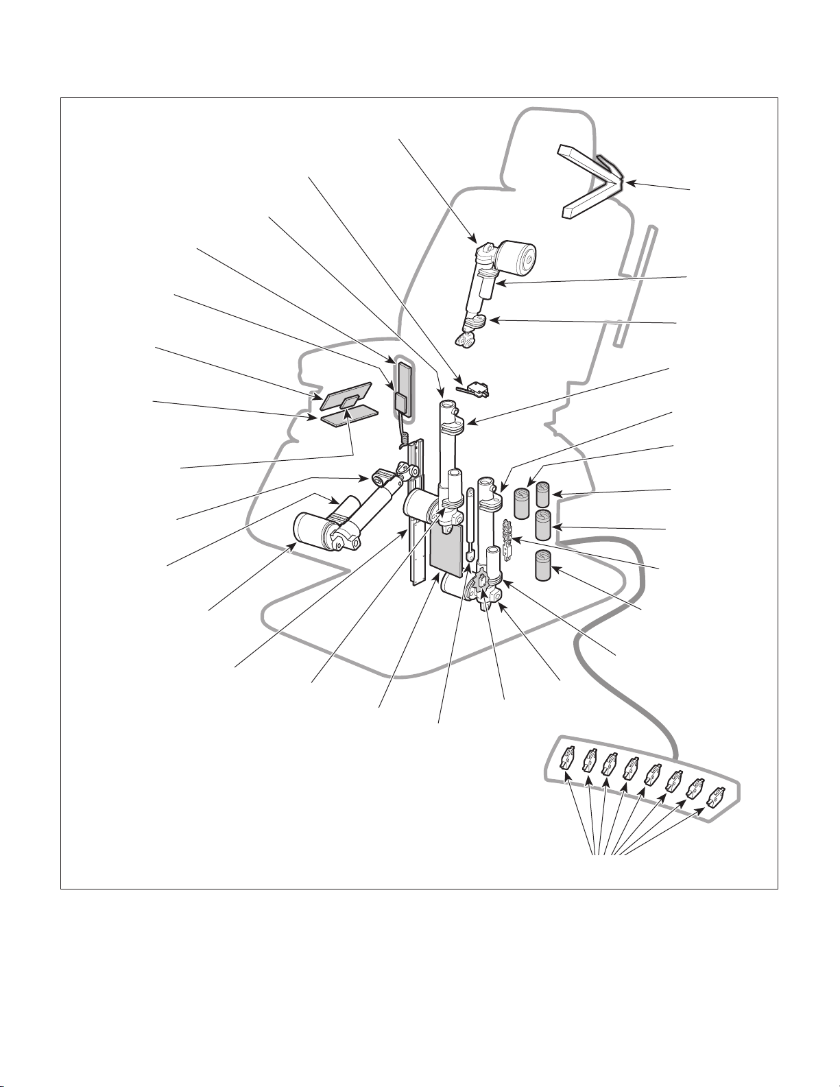
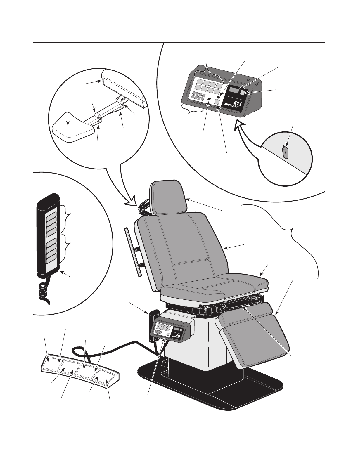
PAN SAFETY
LIMIT SWITCH
TILT
ACTUATOR
HAND CONTROL
PANEL
HAND CONTROL
PC BOARD
PROGRAM
PANEL
BACK
ACTUATOR
HEADLOCK
ASSEMBLY
BACK
RECEIVER
BACK
TRANSMITTER
TILT
TRANSMITTER
PC
LOGIC
BOARD
PROGRAM PANEL
INTERFACE BOARD
FOOT
TRANSMITTER
FOOT
RECEIVER
ACTUATOR
FOOT
BASE
SLIDE
ASSEMBLY
TILT
RECEIVER
INTERFACE
BOARD
GAS
SPRING(S)
BASE
DOWN
LIMIT
SWITCH
BASE
TRANSMITTER
BACK or FOOT
CAPACITOR
(SEE NOTE)
BACK or FOOT
CAPACITOR
(SEE NOTE)
TILT
CAPACITOR
CHAIN
ASSEMBLY
BASE
CAPACITOR
BASE
RECEIVER
BASE
ACTUATOR
NOTE: THE FOOT AND BACK CAPACITORS MAY BE SWITCHED ON
SOME UNITS. CHECK THE WIRE COLORS OF THESE CAPACITORS
TO DETERMINE FOOT OR BACK CAPACITOR LOCATION. RED WIRES
ARE CONNECTED TO THE BACK CAPACITOR AND YELLOW WIRES
ARE CONNECTED TO THE FOOT CAPACITOR.
© Midmark Corporation 1995 SF-1492 Rev. 4/97 Page 1-2 Printed in U.S.A.
Figure 1-1. Major Components
FOOT CONTROL
FOOT SWITCH
MA301800
Page 9

SECTION I
Return To Table Of Contents
GENERAL INFORMATION
Actuator Operation:
The Base, Tilt, Back, and Foot actuators are ball screw
driven. The actuator assemblies contain a pivot point
on the end of the ball screw. If an actuator assembly is
run to the end of its stroke, the ball screw shaft spins
inside the nut, which allows the actuator assembly to
run without damaging or advancing the nut.
The Base, Tilt, Back, and Foot actuators have internal
braking mechanisms which use a friction device to keep
actuator stationary when the actuator is not being run.
Programming Operation:
The model 411 can be programmed for up to eight
operator specified positions. To program a position into
memory, the operator uses the manual positioning
buttons on the hand control or program panel to position the table top in the desired position. Now, the PC
logic board determines the position of each function as
follows: each actuator has a transmitter and a receiver
attached to it; the receiver is mounted to the motor end
of the actuator and is stationary while the transmitter is
mounted to the moving actuator shaft of the actuator.
The PC logic board has the transmitter on each actuator shaft continuously transmit a high frequency sound
wave which is received by its receiver. The PC logic
board compares the transmit point on the wave form
against the receive point on the wave form and uses
this data to determine the distance between the transmitter and receiver for each actuator. The PC logic
board uses this frequency measuring technique to
determine the position of the actuators at all times. The
operator now presses the PROGRAM button followed
by one of the eight PROGRAMMED POSITION buttons. The red L.E.D. under the PROGRAM button will
illuminate when the PROGRAM button is pressed and
will remain illuminated for four seconds to inform the
operator that he / she may now select a PROGRAMMED POSITION button (1 thru 8). After four
seconds, the PROGRAM function will automatically
disable itself if a PROGRAMMED POSITION button
has not been selected. When a PROGRAMMED
POSITION button is pressed, the receive point on the
wave form for each actuator is stored into memory.
Now the operator can easily return to the position
stored in memory. To do so, the operator presses and
holds the PROGRAMMED POSITION button (1 thru 8)
which has the desired position stored in memory. The
PC logic board compares the receive point on the wave
form that is actually being measured by each actuator's
transmitter / receiver set, against the value stored in the
PC logic board's memory. The PC logic board then
energizes the appropriate relays and allows each
actuator to run until the receive point on the wave form
being measured by each actuator's transmitter / receiver set is equal to the value stored in the PC logic
board's memory. When the values are equal, the relays
are de-energized, stopping the actuators.
Auto Return Operation:
When the operator presses the AUTO RETURN button,
the PC logic board energizes the base actuator's down
relay, causing the base actuator to run. The base
actuator lowers until the base down limit switch is
tripped. The PC logic board also senses that the base
down limit switch is tripped and de-energizes the base
actuator relays.
If the operator, at any time, wishes to stop the auto
return function, he / she can press the STOP button.
The PC logic board senses that the STOP button has
been pressed and de-energizes the base actuator
relays, causing the base actuator to stop.
Pan Safety Limit Switch:
The table has a N.O. pan safety limit switch. If the pan
assembly is not pushed into its fully stowed position, the
pan safety limit switch will not be tripped and there will
be an open circuit. If the pan safety limit switch circuit
is open, no power can reach the foot actuator windings,
preventing movement of the FOOT UP and FOOT
DOWN function. This safety feature prevents the
operator from accidentally colliding the foot section into
the treatment pan assembly.
General Information:
All actuator motors have a thermal overload switch
which will activate if the actuator assembly is run
continuously. The actuator motor was not designed for
continuous operation. The normal cool off period for
the thermal overload switches is 10 - 20 minutes.
Each actuator motor has a capacitor which provides
start up power and motor run power.
There is a 0.15 amp fuse, located on the interface
board, which provides over-current protection for the
transformer.
© Midmark Corporation 1995 SF-1492 Rev. 9/97 Page 1-3 Printed in U.S.A.
Page 10

SECTION I
Return To Table Of Contents
GENERAL INFORMATION
There are four 5 amp slow blow fuses, located on the
interface board, which provide over-current protection
for each function's motors (i.e, Tilt fuse protects tilt
actuator motor).
Under the control console, there is an ON / OFF switch.
Turning the switch to OFF disables movement of the
table, preventing accidental table movement or patients
from operating table. A red CONTROL PANEL
POWER L.E.D. illuminates when the ON / OFF switch
is in the ON position.
1.4 Specifications
Factual data for the 411 Power Examination Table is
provided in Table 1-1. Also, see Figure 1-2.
Table 1-1. Specifications
Description Data
Weight:
Without Shipping Carton................ 550 lb (249.5 kg)
With Shipping Carton..................... 625 lb (283.5 kg)
Weight Capacity (Maximum)............. 300 lb. (136.0 kg)
Electrical Requirements:
115 VAC Unit........................... 110 - 120 VAC, 60 HZ,
12 amp, single phase
230 VAC Unit...................... 220 - 240 VAC, 50/60 HZ,
10 amp, single phase
Power Consumption:
115 VAC Unit......................................... 1440 WATTS,
12 amps @ 120 VAC
230 VAC Unit........................................ 2400 WATTS,
10 amps @ 240 VAC
Recommended Circuit:
A separate (dedicated) circuit is recommended for
this table. The table
electrical circuit with other appliances or equipment
unless the circuit is rated for the additional load.
should not
be connected to an
1.5 Parts Replacement Ordering
If a part replacement is required, order the part directly
from the factory as follows:
Shipping Carton....... 58 in. "L" x 42 in. "W" x 31 in. "H"
(147.3 cm x 106.7 cm x 78.7 cm)
Dimensions (See Figure 1-2):
Table Top Length ......................... 70.5 in. (179.0 cm)
Table Top Length (headrest extended).............. 81 in.
(205.7 cm)
Table Top Width ................................ 27 in. (68.6 cm)
Overall Width..................................... 27 in. (68.6 cm)
Table Adjustment:
Back Section ...................................................0 to 85°
Foot Section ...................................................0 to -87°
Tilt Function..................................................... 0 to 42°
Table Top Height (Adjustable): ...................25.75 in. to
41.625 in.
(65.4 cm to 105.7 cm)
Table Speeds:
TABLE UP.........................................12 +/- 1 seconds
BACK UP ..........................................10 +/- 1 seconds
TILT UP.............................................11 +/- 1 seconds
FOOT UP ..........................................10 +/- 1 seconds
(1) Refer to Figure 1-3 to determine the location of
the model number and serial number of the
table and record this data.
(2) Refer to the Parts List to determine the item
numbers of the parts, part numbers of the
parts, descriptions of the parts, and quantities
of parts needed and record this data (Refer to
para 6.1).
NOTE
Ask the Purchasing Department of the company that
owns the table for this information. Otherwise, this
information may be obtained from the dealer that
sold the table.
(3) Determine the installation date of the table and
record this data.
(4) Call Midmark with the recorded information and
ask for the Medical Products Technical Services Department. See back cover of this
manual for the phone number or use the Fax
Order Form (See page 7-2 for Fax Order
Form).
© Midmark Corporation 1995 SF-1492 Page 1-4 Printed in U.S.A.
Page 11
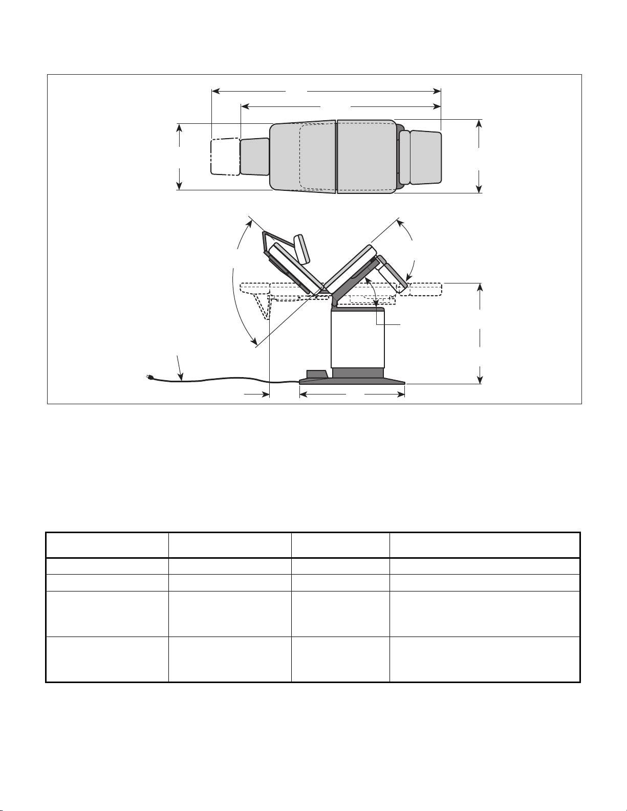
81"
Return To Table Of Contents
SECTION I
GENERAL INFORMATION
70 1/2"
1.6 Special Tools
23 1/2"
(BASE)
POWER
CORD
(78")
85°
(MAX.)
10 1/2"
Figure 1-2. Table Dimensions
33"
87°
(MAX.)
42°
(MAX.)
27"
(TABLE TOP)
41 5/8"
(MAX.)
25 3/4"
(MIN.)
MA301900
Table 1-2 lists all of the special tools needed to repair
the table, how to obtain the special tools, and the
purpose of each special tool.
Table 1-2. Special Tool List
Description of Special Tool
Multimeter Commercially Available Any Type Used to perform continuity and volt age checks.
Torque Wrench Commercially Available Any Type Used to t i ght en nuts or s cr ews to specified v alues .
Support Bar Midmark Corporation
Pry Bar Midmark Corporation
Manufacturer's
Name / Address / Phone
60 Vista Drive
Versai ll es, Ohio 45380
(513) 526-3662
60 Vista Drive
Versai ll es, Ohio 45380
(513) 526-3662
Manufacturer's
Part Number
051-0412-00 Used to support t he weight of the t able t op so t he
base actuator may be disconnected from table.
Used in base actuator rem ova l and gas spring(s)
removal procedures.
051-0413-00 Used to compress t he gas spri ng( s) so they may
be disconnected and removed from table.
Purpose of Special Tool
© Midmark Corporation 1995 SF-1492 Page 1-5 Printed in U.S.A.
Page 12
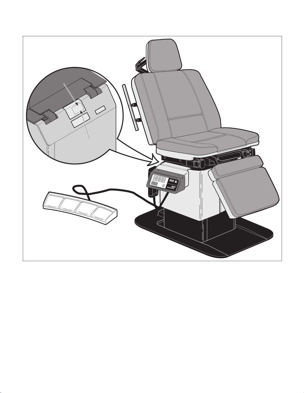
SECTION I
MODEL NO.
INPUT
RATING
SERIAL NO.
411-00X
XXX VAC
XX AMP XX/XX HZ
AVXXXXXX
MIDMARK
Return To Table Of Contents
GENERAL INFORMATION
MODEL
NUMBER
SERIAL
NUMBER
© Midmark Corporation 1995 SF-1492 Page 1-6 Printed in U.S.A.
MA302000
Figure 1-3. Model Number / Serial Number Location
Page 13

TESTING AND TROUBLESHOOTING
Return To Table Of Contents
SECTION II
TESTING AND TROUBLESHOOTING
SECTION II
2.1 Operational Test (See Figure 2-1)
In order to effectively diagnose the malfunction of the
table, it may be necessary to perform an operational
test as follows:
WARNING
Refer to the Operator Manual for
complete instructions on operating the
table. Failure to do so could result in personal
injury.
NOTE
The Operational Test, for the most part, only describes what should happen when the table is
operated. If the table does something other than
described, a problem has been discovered. Refer to
the Troubleshooting Guide to determine the cause of
the problem and its correction.
(1) Plug the table into a grounded, non-isolated,
correctly polarized outlet, that has the proper
voltage output for the table. See Figure 2-1.
NOTE
The pan slide assembly should be pushed in fully for
the following step.
Table Speeds:
TABLE UP.........................................12 +/- 1 seconds
BACK UP ..........................................10 +/- 1 seconds
TILT UP.............................................11 +/- 1 seconds
FOOT UP ..........................................10 +/- 1 seconds
(4) Repeat steps 2 and 3 on the table's console. If
the table has a foot control, repeats steps 2 and
3 for the foot control also.
(5) Lower FOOT DOWN function almost all the
way down. Pull the pan slide assembly outward until the pan safety limit switch is no
longer tripped. Press FOOT UP and then
FOOT DOWN button on hand control.
(6) Observe. The foot section of table top
not
move when FOOT UP or FOOT DOWN
buttons are pressed.
(7) Push pan slide assembly inward until pan
safety limit switch is tripped. Press FOOT UP
and then FOOT DOWN button on hand control.
(8) Observe. The foot section of table top
move when FOOT UP or FOOT DOWN buttons
are pressed.
should
should
(2) Press TABLE UP, TABLE DOWN, BACK UP,
BACK DOWN, TILT UP, TILT DOWN, FOOT
UP, and FOOT DOWN buttons on hand control.
(3) Observe. The table top should move in the
direction corresponding to the button which is
being depressed. No section of the table top
should drift on its own after hand control button
is released. No actuator assembly should
make excessive squealing noises. Movement
should be steady and should match the positions and speeds listed below:
Table Positions:
Back Section ................................................... 0 to 85°
Foot Section ...................................................0 to -87°
Tilt Function..................................................... 0 to 42°
Table Top Height (Adjustable): ...................25.75 in. to
41.625 in.
(65.4 cm to 105.7 cm)
NOTE
Once the PROGRAM button is pressed, the operator
has four seconds to press one of the eight PROGRAMMED POSITION buttons.
(9) Press the PROGRAM button followed by the
PROGRAMMED POSITION button labeled "1".
(10) Observe. When the PROGRAM button is
pressed, the red L.E.D. directly above it should
illuminate.
(11) Use the manual positioning buttons to move the
table top to a new position.
NOTE
Steps 12 thru 14 check functionality of PROGRAMMED POSITION buttons 1 thru 8 on console.
(12) Press and hold the PROGRAMMED POSITION
button "1" (located on console) until the table
top stops moving.
© Midmark Corporation 1995 SF-1492 Page 2-1 Printed in U.S.A.
Page 14
SECTION II
BACK
SECTION
AXIS
"B"
AXIS
"C"
POINT
"A"
LOWER
LOCK
HANDLE
UPPER
LOCK
HANDLE
Return To Table Of Contents
TESTING AND TROUBLESHOOTING
MANUAL
POSITION
BUTTONS
PROGRAMMED
MANUAL
POSITION
BUTTONS
CONTROL
POSITION
BUTTONS
1
2
5
6
7
PANEL
POWER
L.E.D.
3
4
8
PROGRAM
BUTTON
HEADREST
PROGRAM
L.E.D.
SECTION
AUTO RETURN
"STOP" BUTTON
AUTO RETURN
"START" BUTTON
CONTROL PANEL
POWER "ON / OFF"
SWITCH
VIEW
ROTATED 90°
TABLE
TOP
TABLE
UP
BACK
UP
BACK
DOWN
PROGRAMMED
POSITION
BUTTONS
HAND
CONTROL
TABLE
DOWN
TILT
UP
FOOT
UP
DOWN
HAND
CONTROL
TILT
FOOT
DOWN
BACK
SECTION
SEAT
SECTION
FOOT
SECTION
PAN SLIDE
ASSEMBLY
CONSOLE
MA302100
Figure 2-1. Operational Test
© Midmark Corporation 1995 SF-1492 Page 2-2 Printed in U.S.A.
Page 15

SECTION II
Return To Table Of Contents
TESTING AND TROUBLESHOOTING
(13) Observe. The table top should move back to
the position that was stored into memory of "1"
in step 9.
(14) Repeat steps 9 thru 13 to test the PRO-
GRAMMED POSITION buttons "2 thru 8" on
the console.
NOTE
Steps 15 thru 17 check functionality of PROGRAMMED POSITION buttons 1 thru 8 on hand
control.
(15) Press and hold the PROGRAMMED POSITION
button "1" (located on hand control) until the
table top stops moving.
(16) Observe. The table top should move back to
the position that was stored into memory of "1"
in step 9.
(17) Repeat steps 15 and 16 to test the PRO-
GRAMMED POSITION buttons "2 thru 8" on
the hand control.
(18) Press the TABLE UP button to run the table top
all the way up.
(19) Press the AUTO RETURN "START" button,
wait one second, and then press the AUTO
RETURN "STOP" button.
(20) The base actuator should begin to lower the
table top. When the STOP button is pressed,
the base actuator should stop lowering.
(23) Switch the CONTROL PANEL POWER switch
to OFF.
(24) Observe. The CONTROL PANEL POWER
L.E.D. should extinguish when the switch is
switched to OFF.
(25) Press one of the MANUAL POSITION buttons
or PROGRAMMED POSITION buttons.
(26) Observe. The table top should not move when
a MANUAL POSITION button or PROGRAMMED POSITION button is pressed.
NOTE
Early units have a headrest which has only one
locking handle. The procedure is the same otherwise.
(27) Unlock upper lock handle and lower lock
handle, position headrest in a horizontal
position as shown, and then relock upper lock
handle and lower lock handle.
(28) Place a 45 lb (20.4 kg) static load at Point A.
(29) Observe. There should be no movement at
Axis B or Axis C when the static load is applied
to the headrest. The maximum force required
to unclamp a locking handle should be 17 lbs.
(7.7 kg) and the maximum force required to
clamp a locking handle should be 35 lbs. (15.8
kg).
2.2 Troubleshooting Procedures
(21) Press the AUTO RETURN "START" button and
allow the table top to lower all the way down.
(22) Observe. The base actuator should lower the
table top all the way down. The base actuator
should not continue to run after table top is
completely lowered.
© Midmark Corporation 1995 SF-1492 Page 2-3 Printed in U.S.A.
Table 2-1 is a Troubleshooting Guide which is used to
determine the cause of the malfunction.
Page 16

SECTION II
Return To Table Of Contents
TESTING AND TROUBLESHOOTING
Table 2-1. Troubleshooting Guide
Problem Symptom Probable Cause Check Correction
Table will not o p e rate
when any of the eight up
or down functions, auto
return, or programmed
positions ar e selected from
the hand control or
console.
When any hand control or
console but ton is pressed,
nothing happens (actuator
motor(s) does not run or
hum).
Nothing hap pens when a
hand contro l or console
button is pressed, but table
runs when a foot control
switc h i s depresse d.
Power cord is not plugged
into facility wall outlet.
CONTR OL PA NE L PO W ER
switch is OFF.
Facility circuit breaker
providing power t o table is
tripped.
Wire conn ect ions loo se. Check all wiring
0.15 amp transformer
primary fuse on interface
board is blown.
Interface board is
malfunctioning.
PC logic board is
malfunctioning.
PC logic board is
malfunctioning.
Check to see if power
cord is plug ged i n.
Check to see if
CONTROL PANEL
POWER switch is ON.
CONTROL PANEL
POWER L.E.D. should
illuminat e to in dicat e
switch is ON.
Check t o see if f acility
circuit br eaker is tripped.
One way of checking this
is to plug a lamp into wall
outlet that table was
plugged into.
connections from power
cord to terminal block
and from terminal block
to interface board.
Perform cont inuit y check
on wires. Use
multimeter to check for
proper v oltage levels.
Refer to Figure 5-1 or
5-2 for this check.
Perform cont inuit y check
on primary fuse.
Replace suspect
interface board with
known wo rking interface
board.
Replace suspect PC logic
board with known
working PC logic board.
Replace suspect PC logic
board with known
working PC logic board.
Plug power cor d into f a c ility
wall outlet.
Turn CONTROL PANEL
POWER switch to ON. Inform
operator on use of the switch.
If the table does not work
even when the switch is in ON
positi on, replace PC logic
board. Refer to para 4.6.
If circuit breaker is tripped,
determine what caused circu it
breaker to trip, correct the
problem, and then reset /
replace circ uit breaker.
Clean any dirt y con ne ct ions.
Tighten any loose
connec tions. Replace any
damaged connections.
Replace blown prim ary fuse.
See Figure 5-1 or 5-2 for
location of fuse.
Replace interface board.
Refer to para 4.4 or 4.5.
Replace PC logic board.
Refer to para 4.6.
Replace PC logic board.
Refer to para 4.6.
© Midmark Corporation 1995 SF-1492 Page 2-4 Printed in U.S.A.
Page 17

Problem Symptom Probable Cause Check Correction
Return To Table Of Contents
One or more funct ions
cannot be initiated from
the hand control.
Table 2-1. Troubleshooting Guide - Continued
Some funct ions may be
initiated from the hand
control, but at least one
may not . All functions can
be initiated from the
console.
TESTING AND TROUBLESHOOTING
Hand control panel of hand
control is malfunctioning
(switch membrane is
malfunctioning).
Hand control board is
malfunc t ioning.
Hand co ntrol coil cor d has
bad connection or there is a
break in coil cord.
Replace suspect h and
control panel with known
working hand c ont rol
panel.
Replace suspect h and
control board with known
working hand c ont rol
board.
Replace suspect c oi l cord
with known working coil
cord.
SECTION II
Replace hand control panel.
Refer to para 4.8.
Replace hand control board.
Refer to para 4.8.
Replace coil cord.
One or more funct ions
cannot be initiated from
the cons ole.
One or more funct ions
cannot be initiated from
the optional foot control.
Some funct ions may be
initiated from the consol e,
but at least one may not.
All functions c an be
initiated from the hand
control.
Some funct ions may be
initiated from the foot
control, but at least one
may not . All functions can
be initiated from t he hand
contr ol an d console.
Program p anel i s
malfunc t ioning ( swi tch
membrane i s
malfunct ioning ) .
Program panel interface
board is malfunctioning.
Wire conn ect ions loo se. Check all wiring
Foot switch for
non-opera ble function is
malfunctioning.
Wire conn ect ions loo se. Check all wiring
Replace suspect
program panel with
known working program
panel.
Replace suspect
program panel interface
board with known
working program panel
interface board.
connections from
program panel to
program panel interface
board to PC logic board.
Perform cont inuit y check
on wires. Use
multimeter to check for
proper v oltage levels.
Perform a continuity
check o n suspect foot
switch.
connections from foot
control to interface
board. Perform
continu ity check on wires.
Use multimeter to check
for proper voltage levels.
Replace program panel.
Refer to para 4.7.
Replace program panel
interface board. Refer to
para 4.7.
Clean any dirt y con ne ct ions.
Tighten any loose
connec tions. Replace any
damaged connections.
Replace foot switch. Refer to
para 4.27.
Clean any dirt y con ne ct ions.
Tighten any loose
connec tions. Replace any
damaged connections.
© Midmark Corporation 1995 SF-1492 Page 2-5 Printed in U.S.A.
Page 18

SECTION II
Return To Table Of Contents
TESTING AND TROUBLESHOOTING
Table 2-1. Troubleshooting Guide - Continued
Problem Symptom Probable Cause Check Correction
BACK UP and BACK
DOWN funct i ons do not
work. All o t her functions
work.
TILT UP and TILT DOWN
functions do not work. All
other functions work.
When BACK UP and
BACK DOWN buttons are
pres sed, the table will not
move (all other functions
work).
When TILT UP and TILT
DOWN buttons are
pres sed, the table will not
move (all other functions
work).
BACK capacitor is weak o r
blown.
Thermal over l oad switch in
back actuat or is activated.
5 amp BACK fuse fo r BACK
UP and BA CK DOWN
functions is blown (located
on interface board).
Back ac t uator assembly is
malfunctioning.
Wire conn ect ions loo se. Check all wiring
Interface board is
malfunctioning
Tilt capacitor is weak or
blown.
Thermal over l oad switch in
tilt act uat or is activated.
5 amp TILT fuse for TILT
UP and TILT DOWN
functions is blown (located
on interface board).
Tilt actuator assembly is
malfunctioning.
Wire conn ect ions loo se. Check all wiring
Interface board is
malfunctioning
Replace suspect b ack
capacitor wit h known
working back capacitor.
- Wait 10 to 20 minutes to allow
Refer to Figure 2-2 for
this check. Perform a
continu ity che ck on 5
amp BACK fuse.
Replace suspect b ack
actuator assembly with
known working back
actuator assembly.
connec t ions to back
actuator assembly.
Replace suspect
interface board with
known wo rking interface
board.
Replace suspect tilt
capacitor wit h known
working tilt capacitor.
- Wait 10 to 20 minutes to allow
Refer to Figure 5-1 or
5-2 for this check.
Perform a continuity
check on 5 amp TILT
fuse.
Replace suspect tilt
actuator assembly with
known working tilt
actuator assembly.
connections to tilt
actuator assembly.
Replace suspect
interface board with
known wo rking interface
board.
Replace back capacitor.
Refer to para 4.10.
back actuator motor t o cool.
Replace b lown BACK fuse.
See Figure 5-1 or 5-2 for
location of fuse.
Replace actuator motor or
back actuator assembly.
Refer to para 4.21 or 4.12.
Clean any dirt y con ne ct ions.
Tighten any loose
connec tions. Replace any
damaged connections.
Replace interface board.
Refer to para 4.4 or 4.5.
Replace tilt capacitor. Refer
to para 4.10.
tilt actuator motor t o cool.
Replace blown TILT fuse.
See Figure 5-1 or 5-2 for
location of fuse.
Replace actuator motor or t ilt
actuator assembly. Refer to
para 4.21 or 4.16.
Clean any dirt y con ne ct ions.
Tighten any loose
connec tions. Replace any
damaged connections.
Replace interface board.
Refer to para 4.4 or 4.5.
© Midmark Corporation 1995 SF-1492 Page 2-6 Printed in U.S.A.
Page 19

Problem Symptom Probable Cause Check Correction
Return To Table Of Contents
TABLE UP and TABLE
DOWN functions do not
work. All o t her functions
work.
FOOT UP and FOOT
DOWN functions do not
work. All o t her functions
work.
Table 2-1. Troubleshooting Guide - Continued
When TABLE UP and
TABLE DOWN buttons are
pressed, t he table will not
move (all o t her functions
work).
When FOOT UP and
FOOT DOWN buttons are
pressed, t he table will not
move (all o t her functions
work).
TESTING AND TROUBLESHOOTING
Base capacit or i s wea k or
blown.
Thermal ove rload switch in
base actuator is activated.
5 amp TABLE fuse for
TABLE UP and TABLE
DOWN functions is blown
(located on interface board).
Base act uat or asse mbly is
malfunctioning.
Wire connections loose. Check all wiring
Interface board is
malfunctioning
Pan holder as se mbly is no t
pushe d in all the way;
therefore the pan saf et y limit
switch is not t r ipped.
Foot capacitor is weak or
blown.
Thermal ove rload switch in
foot ac tuator is activated.
5 amp FOOT fuse for FOOT
UP and FOOT DOWN
funct ions is bl own ( located
on interface board).
Foot act uator assembly is
malfunctioning.
Wire connections loose. Check all wiring
Interface board is
malfunctioning
Replace sus pe ct ba se
capacitor with known
working base capacitor.
- Wait 10 to 20 minutes t o allow
Refer to Figure 2-2 for
this check. Perform a
conti nuity check on 5
amp TABLE f use.
Replace sus pe ct ba se
actuator assembly with
known working base
actuator assembly.
connec tions to base
actuator assembly.
Replace su spec t
interface board with
known working interface
board.
Check that pan holder
assembly is pushed in all
the way.
Replace suspect foot
capacitor with known
workin g foot capacit or.
- Wait 10 to 20 minute s t o allow
Refer to Figure 2-2 for
this check. Perform a
conti nuity check on 5
amp FOOT fuse.
Replace suspect foot
actuator assembly with
known working foot
actuator assembly.
connec tions to base
actuator assembly.
Replace su spec t
interface board with
known working interface
board.
SECTION II
Replace base capacitor.
Refer to para 4.10.
base actuator motor to cool.
Replace blown TABLE f use.
See Figure 5-1 or 5-2 for
location of fuse.
Replace actuator motor or
base actuator assembly.
Refer to para 4.21 or 4.18.
Clean any dir ty conn ect ions.
Tighten an y loo se
conne ctions. Replace any
damaged connections.
Replace interface board.
Refer to para 4.4 or 4.5.
Push pan holder assembly in
all the way. Inform operator
on how the pan safety limit
switch works.
Replace foot capacitor. Refer
to para 4.10.
foot actuator motor to cool.
Replace blown FOOT fuse.
See Figure 5-1 or 5-2 for
location of fuse.
Replace actuator motor or
foot actuator assembly. Refer
to para 4.21 or 4.14.
Clean any dir ty conn ect ions.
Tighten an y loo se
conne ctions. Replace any
damaged connections.
Replace interface board.
Refer to para 4.4 or 4.5.
© Midmark Corporation 1995 SF-1492 Page 2-7 Printed in U.S.A.
Page 20

SECTION II
Return To Table Of Contents
TESTING AND TROUBLESHOOTING
Table 2-1. Troubleshooting Guide - Continued
Problem Symptom Probable Cause Check Correction
FOOT UP and FO OT DOWN
functions do no t work. All
other functions work Continued.
BACK UP function works, but
BACK DOWN function does
not or BACK DOWN function
works, but BACK UP function
does not. All other functions
work.
TILT UP function works, but
TILT DOWN function does
not or TILT DOW N func tio n
works, but TILT UP function
does not. All other functions
work.
TABLE UP function works,
but TABLE DOWN function
does not or TABLE DOWN
function works, but TABLE
UP function does not. All
other functions work.
When FOOT UP and
FOOT DOWN buttons
are pressed, the table will
not move (all other
functions work) Continued.
One function operates
properly, but the other
does not.
One function operates
properly, but the other
does not.
One function operates
properly, but the other
does not.
TABLE UP does not
work, but TABLE DOWN
Pan safety switch is out of
adjustment.
Pan sa fe ty limit switch is
malfunctioning.
Wire connections loose. Check all wiring
Interface board is
malfunctioning (relay for up
or down function is
malfunctioning).
Back actuator assembly is
malfunctioning.
Wire connections loose. Check all wiring
Interface board is
malfunctioning (relay for up
or down function is
malfunctioning).
Tilt actuator assembly is
malfunctioning.
Wire connections loose. Check all wiring
Interface board is
malfunctioning (relay for up
or down function is
malfunctioning).
Base actuator assembly is
malfunctioning.
Gas spring(s) are weak. Replace suspect gas
Check to see if pan
safety limit switch is b e in g
tripped by pan holder
assembly.
Perform continuity check
on pan sa fety limit switch
(switch tripped = closed).
conne ctions to back
actuator ass embly.
Replace suspect
interface board with
known working interface
board.
Replace suspect back
actuator assembly with
known working back
actuator ass embly.
connections to tilt
actuator ass embly.
Replace suspect
interface board with
known working interface
board.
Replace suspect tilt
actuator assembly with
known working tilt
actuator ass embly.
connections to base
actuator.
Replace suspect
interface board with
known working interface
board.
Replace suspect base
actuator assembly with
known working base
actuator ass embly.
spring(s) with known
p
Adjust pa n safety limit switch
so it is tripped when pan
holder assembly is pushed in
all the way.
Replace pan safety limit
switch. Refer to para 4.9.
Clean any dirty c onnecti ons.
Tighten any loose
connections. Replace any
damaged connections.
Replace interface board.
Refer to para 4.4 or 4.5.
Replace actuator motor or
back actuator assembly.
Refer to para 4.21 or 4.12.
Clean any dirty c onnecti ons.
Tighten any loose
connections. Replace any
damaged connections.
Replace interface board.
Refer to para 4.4 or 4.5.
Replace actuator motor or tilt
actuator assembly. Refer to
para 4.21 or 4.16.
Clean any dirty c onnecti ons.
Tighten any loose
connections. Replace any
damaged connections.
Replace interface board.
Refer to para 4.4 or 4.5.
Replace actuator motor or
base actuator assembly.
Refer to para 4.21 or 4.18.
Replace gas spring(s). Refer
to para 4.19.
© Midmark Corporation 1995 SF-1492 Page 2-8 Printed in U.S.A.
Page 21

Problem Symptom Probable Cause Check Correction
Return To Table Of Contents
FOOT UP function works,
but FOOT DOWN function
does not or FOOT DOWN
function works, but FOOT
UP function does not. All
other functions work.
Programming function is
malfunctioning.
Table 2-1. Troubleshooting Guide - Continued
One function operates
properly, but the other
does not.
A table position cannot be
programmed into
memory.
TESTING AND TROUBLESHOOTING
Wire connections loose. Check all wiring
Interface board is
malfunctioning (relay for up
or down function is
malfunctioning).
Foot actuator assembly is
malfunctioning.
The receiver and
transmitter for a function
are not properly aligned or
are malfunctioning,
resulting in a lost signal.
RF cables for receiver and
transmitter are shorted or
open.
connections to foot
actuator assembly.
Replace suspect
interface board with
known working interface
board.
Replace suspect foot
actuator assembly with
known working foot
actuator assembly.
Refer to Figure 5-1or
5-2 for this check. Check
L.E.D. (D1-Base,
D2-Foot, D3-Back, and
D4-Tilt) on PC logic
board. If L.E.D. is
illuminated, transmitter or
receiver for that function
could be out of
alignment. Align the
receiver and transmitter
for a function and then
see if the table goes to
the proper position when
a PROGRAMMED
POSITION button is
pressed.
Perform continuity check
on RF cables.
SECTION II
Clean any dirty connections.
Tighten any loose
connections. Replace any
damaged connections.
Replace interface board.
Refer to para 4.4 or 4.5.
Replace actuator motor or
foot actuator assembly. Refer
to para 4.21 or 4.14.
Align the receiver and
transmitter of a function. If
this does not correct problem,
replace receiver and
transmitter for the suspect
function. Refer to para 4.11
for back function, para 4.13
for foot function, para 4.15 for
tilt function, para 4.17 for base
function.
Replace any damaged RF
cables.
Program panel is
malfunctioning (switch
membrane is
malfunctioning).
Program panel interface
board is malfunctioning.
PC logic board is
malfunctioning.
Replace suspect
program panel with
known working program
panel.
Replace suspect
program panel interface
board with known
working program panel
interface board.
Replace suspect PC logic
board with known
working PC logic board.
Replace program panel.
Refer to para 4.7.
Replace program panel
interface board. Refer to
para 4.7.
Replace PC logic board.
Refer to para 4.6.
© Midmark Corporation 1995 SF-1492 Page 2-9 Printed in U.S.A.
Page 22

SECTION II
Return To Table Of Contents
TESTING AND TROUBLESHOOTING
Table 2-1. Troubleshooting Guide - Continued
Problem Symptom Probable Cause Check Correction
Program ming funct ion is
malfunct ioning - Continued.
When a PROGRAMMED
POSITION button is
pressed, the table top
does not move to the
proper position that was
stored in memory.
The receiver and
transmitter for a function
are not properly aligned or
are m alfunctioning,
res ul t ing in a los t si gna l.
Refer to Figure 2-1 for
this check. Check L.E.D.
(D1-Base, D2-Foot,
D3-Back, and D4-Tilt) on
PC logic board. If L.E.D.
is illumin at ed , t ra nsm it te r
or receiver for that
function coul d be out of
alignment. Align the
receiver and transmitter
for a function and then
see if t he t able goes to
the proper position when
a PROG RAM M ED
POSITION button is
pressed.
Align the r eceiver and
transmitter of a function. If
this does not correct problem,
replace receiver and
transmitter for t he suspect
function. Refer to para 4.11
for back function, para 4. 13
for foot function, para 4.15 for
tilt function, para 4.17 f or base
function.
AUTO RETURN function
does not work.
The Base, Tilt, Back, or Foot
function drifts by its elf.
When AUTO RETURN
“START” button is
pressed, nothi ng
happens.
After base actuator has
lowered table top all the
way down, the base
actuator continues to run.
Function operat es
properly otherwise.
The receiver or transmitter
for a funct ion is
malfunctioning, but its
L.E. D. indicator light is not
illuminated on the interface
board.
PC logic boar d is
malfunctioning.
Program panel is
malfunctioning (switch
membrane is
malfunctioning).
Program panel interface
board is malfunctioning.
Base down lim it swi tch is
malfunctioning (stuck
open).
Base down lim it swi tch is
out of adjustment.
Base down lim it swi tch is
malfunctioning (stuck
closed).
Motor actuator br ake is
malfunctioning.
Replace suspect receiver
and transmitter with
known working receiver
and transmitter.
Replace suspect PC logic
board with known
working PC logic board.
Replace suspect
program panel with
known working program
panel.
Replace suspect
program panel interface
board with known
working program panel
interface board.
Perform cont inuit y check
on base down limit
switch.
Check adjustm ent of
base do wn li m i t switch.
Perform cont inuit y check
on base down limit
switch.
Replace suspect actuator
brake com ponents with
new components.
Replace receiver and
transmitter for suspect
function. Refer to para 4.11
for back function, para 4. 13
for foot function, para 4.15 for
tilt function, para 4.17 f or base
function.
Replace PC logic board.
Refer to para 4.6.
Replace program panel.
Refer to para 4.7.
Replace program panel
interface board. Refer to
para 4.7.
Replace bas e down lim it
switch. Refer to para 4.20.
Adjust base down limi t switch.
Refer to para 4.20.
Replace bas e down lim it
switch. Refer to para 4.20.
Replace actuator brake
components. Refer to para
4.21.
© Midmark Corporation 1995 SF-1492 Page 2-10 Printed in U.S.A.
Page 23

Table 2-1. Troubleshooting Guide - Continued
Return To Table Of Contents
Problem Symptom Probable Cause Check Correction
Table moves fine for light
patient, but will not move or
moves slowly for very heavy
patient.
Whirling or squeaking noise
is heard when an actuator
assembly is being run.
Excessive sideways play of
table top.
Headrest is not operating
properly.
Stirrups are malfunctioning. Stirrups do not lock into
Heavy patients cause
table to malfunction.
Noisy actuator. Foreign matter on ball
Table is not stable and
can be moved from side
to side.
Headrest drifts downward
while supporting patients
head.
Headrest locking handles
pop out of locked position.
one of the three positions
properly.
TESTING AND TROUBLESHOOTING
Low voltage is being
supplied to table.
Gas spring(s) are weak. Replace suspect gas
Table overloaded with too
heavy of a patient.
Capacitor for suspect
function is weak.
screw threads and / or lack
of lubricant.
Chain assemblies are
loose.
Base slide assembly is
worn or deformed.
Table base is not resting
firmly on floor.
Headrest is out of
adjustment.
Headrest handles handle
stops need adjusted.
Stirrup index pin needs
replaced.
Check voltage at wall
receptacle - should be
115 +/- 5 VAC.
spring(s) with known
working gas spring(s).
Maximum weight
capacity of table is 300
lbs (136.0 kg).
Replace suspect
capacitor with known
working capacitor.
Check for foreign matter
on ball screw threads.
Check for lack of
lubricant on ball screw
threads.
Check tension of chain
assemblies.
Check condition of base
slide assembly.
Check to verify all four
leveling screws are
contacting the floor.
Check adjustment of
headrest.
Check adjustment of
headrest handles handle
stops.
Check for damaged
parts.
SECTION II
Correct low voltage situation
at wall receptacle.
Replace gas spring(s). Refer
to para 4.19.
Inform table operator of
weight limitation.
Replace capacitor.
Clean all foreign matter off of
ball screw threads. Coat ball
screw threads with STP
treatment oil or equivalent. If
actuator assembly is still noisy,
replace it.
Adjust tension of chain
assemblies. Refer to para
4.22.
Replace base slide assembly.
Adjust the leveling screws;
there is one located under
each corner of the base.
Adjust headrest. Refer to
para 4.23 or 4.25.
Adjust headrest handles
handle stops. Refer to para
4.24 or 4.26.
Replace stirrup index pin or
any other necessary
components. Refer to para
4.28.
© Midmark Corporation 1995 SF-1492 Page 2-11 Printed in U.S.A.
Page 24

SECTION II
Return To Table Of Contents
TESTING AND TROUBLESHOOTING
© Midmark Corporation 1995 SF-1492 Page 2-12 Printed in U.S.A.
Page 25

SCHEDULED MAINTENANCE
Return To Table Of Contents
SECTION III
SCHEDULED MAINTENANCE
SECTION III
3.1 Scheduled Maintenance
periodically on the table. These inspections and
services should be performed as often as indicated in
Table 3-1 is a Scheduled Maintenance Chart which lists
the chart.
the inspections and services that should be performed
Table 3-1. Scheduled Maintenance Chart
Interval Inspection or Service What to Do
Semi-ann ua lly Obvious damage Visually che ck condit ion of tabl e for obv ious dam ag e suc h as: crack s in compo ne nt s, mi ssing
Fasteners / hardware Check table for missing or loose fasteners / hardware. Rep lace any missing hardware and tighten
Warning and instructional
decals
Pivot points / moving
parts / accessories
Hand control Check that hand control works correctly. Make sur e all switch membranes work cor r ectly. If
Program panel Check that program panel works correctly. Make sure all switch membranes work correctly. If
Foot control (optional) Check t hat foot control works correctly. Make sure all footswit ches operate pr operly. Replace any
Ball screws of actuator
assemblies
Drifting of actuator
assemblies
Foot ext ension Check tha t foot extension can be easily removed. Make sure foot section is latched sec urely in
Stirr up ass em blies Check that stirrup assem blies lock into one of three positions. Check for wear . Replace worn
Pan safety limit switch Check t hat pan safety lim it switch is tripped when pan assembly is in fully stowed posi t io n. Adjust
Excessive play in column
assembly
Head rest Check that head r est is adjusted properly and will not drift downwar d on it s own under 45 lbs
Elect r ical receptacle
(Domest ic units only)
Upholstery Check all upholstery for rips, tears, or excessive wear. Repla ce cushions as necessary.
Accessories Check t hat all accessories have all of their com ponents and that they fun ct ion properly. I f
Opera tional Test Perform an Operational Test to determine if the table is operating within its specifications (Refer to
components, dents in components, o r any other visible damage which would cause table to be
unsafe to operat e or would comprom ise its performance. Repair table as necessary.
any loose har dw ar e as necessary.
Check f or missing or illegible decals. Re place decals as neces sary.
Lubricate all exposed pivot points, moving parts, and accessories with silicone based lubricant.
necessary, replace hand contr ol panel. Refer to par a 4. 8.
necessary, replace program panel. Ref er to para 4.7.
malfunctioning footswitches. Refer t o para 4.27.
Extend each actuator assem bly and wipe ball screw threads down with a rag to remove foreign
matter. Coat as much of the ball screw threads as possible with STP treatment oil or equivalent.
Run each act uator assemb ly to both ends of its travel a co uple of times t o spread the oil evenly
over all of the ball screw th r eads and then rem ove excess oil. If oil does not correct a squealing
actuat or assembly, replac e actuator assembly.
Check each actuator assembly for d r ift. Replace actuator assem bly brake components as
necessary. Refer to para 4.21.
place when installed.
components as necessary. Refer to para 4.28.
or replace pan safety limit switch if necessary. Refer t o para 4.9.
Check tha t column assembly does not have excessi ve si de t o side play. I f necessary, ti ght en
chain. Refer to par a 4. 22. I f t his does not cor re ct pr oblem, r eplace base slide assembly.
(20.4 kg) of static weight. If necessary, adjust head rest. Ref er t o par a 4. 23 or 4. 25
Check tha t the electrica l receptacle is fun ct ioning properly. Replace r eceptacle as ne cessary.
necessary, repair or replace the access or y.
para 2.1). Replace or adjust any malf unct ioning compo nents .
© Midmark Corporation 1995 SF-1492 Page 3-1 Printed in U.S.A.
Page 26

SECTION III
Return To Table Of Contents
SCHEDULED MAINTENANCE
© Midmark Corporation 1995 SF-1492 Page 3-2 Printed in U.S.A.
Page 27
4.1 Introduction
Return To Table Of Contents
SECTION IV
MAINTENANCE / SERVICE
SECTION IV
MAINTENANCE / SERVICE INSTRUCTIONS
6
WARNING
Refer to the Operator Manual for
complete instructions on operating the
table. Failure to do so could result in personal
injury.
NOTE
Perform an operational test on the table after the
repair is completed to confirm the repair was properly
made and that
The following paragraphs contain removal, installation, repair, and adjustment procedures for the table.
all
malfunctions were repaired.
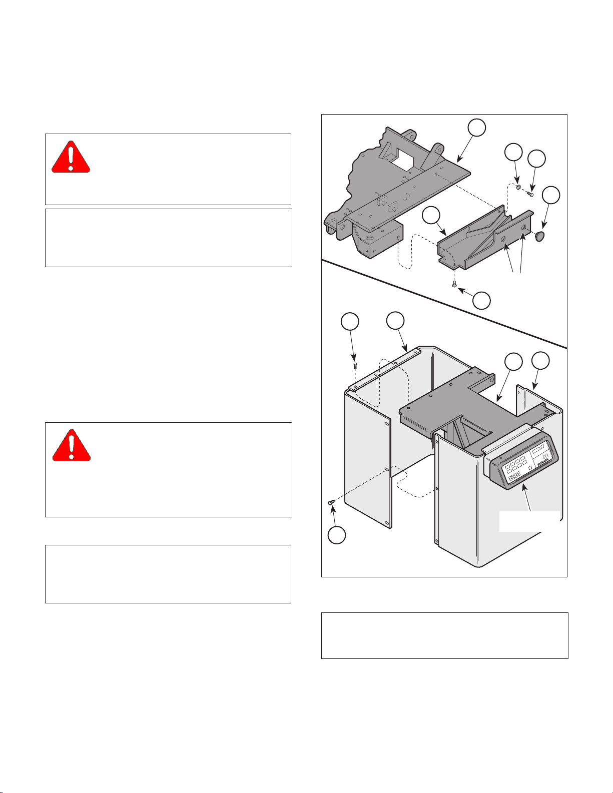
4.2 Shrouds Removal / Installation (Applies to Units With Serial Numbers
AV-1000 Thru AV2888)
A. Removal
(1) If possible, raise TILT UP function all the way
up.
WARNING
Always disconnect the power cord
from the wall outlet before removing
any of the table's covers / shrouds or making any
repairs to prevent the possibility of electrical
shock. Failure to comply with these instructions
could result in severe personal injury or death.
(2) Unplug table power cord from wall outlet.
3
2
1
5
ACCESS
HOLES
4
9
8
8
10
OPERAT OR'S
CONSOLE
7
NOTE
Remove guide weldment (5) from side of table which
does not have operator's console. Also, early units
do not have access holes with plugs (1).
(3) Remove two plugs (1, Figure 4-1) from access
holes; then remove two screws (2),
lockwashers (3), two screws (4) and guide
weldment (5) from seat weldment (6).
(4) Remove six screws (7) securing R.H. and L.H.
shrouds (8) together.
© Midmark Corporation 1995 SF-1492 Page 4-1 Printed in U.S.A.
MA302200
Figure 4-1. Shrouds Removal / Installation
NOTE
Remove shroud from side of table which does not
have operator's console.
(5) Remove two screws (9) and either L.H. or R.H.
shroud (8) from inner member weldment (10).
Page 28
SECTION IV
Return To Table Of Contents
MAINTENANCE / SERVICE
B. Installation
(1) Coat threads of two screws (9) with removable
threadlocking adhesive (Loctite 242).
(2) Install shroud (8) on inner member weldment
(10) and secure with two screws (9).
(3) Secure L.H. and R.H. shrouds (8) together with
six screws (7).
(4) Install guide weldment (5) on seat weldment (6)
and secure with two screws (4), lockwashers
(3), and screws (2).
NOTE
Early units do not have access holes with plugs.
(5) Install two plugs (1) in access holes.
(6) Plug table power cord into wall outlet.
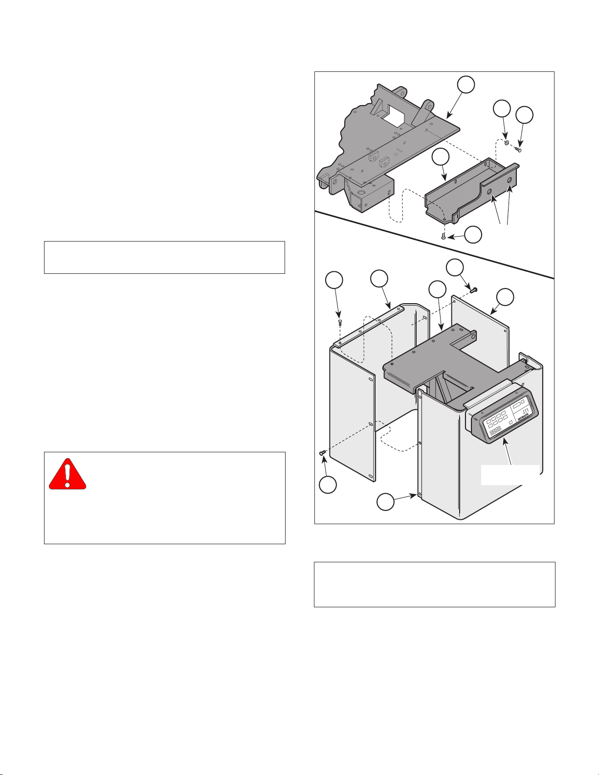
10
9
7
6
8
ACCESS
5
HOLES
1
3
11
2
4.3 Shrouds Removal / Installation (Applies to Units With Serial Numbers
AV-2889 Thru Present and DJ-1000
Thru Present)
A. Removal
(1) If possible, raise TILT UP function all the way
up.
WARNING
Always disconnect the power cord
from the wall outlet before removing
any of the table's covers / shrouds or making any
repairs to prevent the possibility of electrical
shock. Failure to comply with these instructions
could result in severe personal injury or death.
(2) Unplug table power cord from wall outlet.
(3) Remove six screws (1, Figure 4-2) and cover
(2) from R.H. and L.H. shrouds (3).
(4) Remove three screws (4) securing R.H. and
L.H. shrouds (3) together.
OPERAT OR'S
4
CONSOLE
3
Figure 4-2. Shrouds Removal / Installation
NOTE
Remove stirrup housing from side of table which
does not have operator's console.
(5) Remove one screw (5), two screws (6),
lockwashers (7), and stirrup housing (8) from
seat weldment (9).
MA302300
© Midmark Corporation 1995 SF-1492 Page 4-2 Printed in U.S.A.
Page 29

NOTE
Return To Table Of Contents
Remove shroud from side of table which does not
have operator's console.
(6) Remove two screws (10) and either L.H. or
R.H. shroud (3) from inner member weldment (11).
B. Installation
(1) Coat threads of two screws (10) with removable
threadlocking adhesive (Loctite 242).
(2) Install shroud (3) on inner member weldment
(11) and secure with two screws (10).
(3) Secure L.H. and R.H. shrouds (3) together with
three screws (4).
SECTION IV
MAINTENANCE / SERVICE
(2) Unplug table power cord from wall outlet.
(3) If TABLE UP function cannot be raised all the
way up, remove shrouds (Refer to para 4.2 or
4.3).
(4) Remove two screws (1, Figure 4-3) and back
lower shroud (2) from L.H. and R.H support
channels (3).
(5) Tag and disconnect four wire harnesses (4)
from connectors of interface board (5).
(6) Tag and disconnect three wires (6) from
terminals of interface board (5).
(7) Remove four screws (7), starwashers (8),
interface board (5), and spacers (9) from
brace (10).
(4) Install stirrup housing (8) on seat weldment (9)
and secure with two lockwashers (7), screws
(6), and one screw (5).
(5) Install cover (2) on R.H. and L.H. shrouds (3)
and secure with six screws (1).
(6) Plug table power cord into wall outlet.
4.4 Interface Board Removal / Installation
(Early Units)
NOTE
This procedure applies to units with Serial Number
AV-1000 Thru AV-2217 and also AV-2229, AV-2231,
AV-2236, AV-2238, AV-2244, AV-2247, and AV-
2248.
A. Removal
(1) If possible, raise TABLE UP function all the way
up.
WARNING
Always disconnect the power cord
from the wall outlet before removing
any of the table's covers / shrouds or making any
repairs to prevent the possibility of electrical
shock. Failure to comply with these instructions
could result in severe personal injury or death.
B. Installation
NOTE
Four new standoffs, starwashers, and screws are
supplied with the new interface board kit.
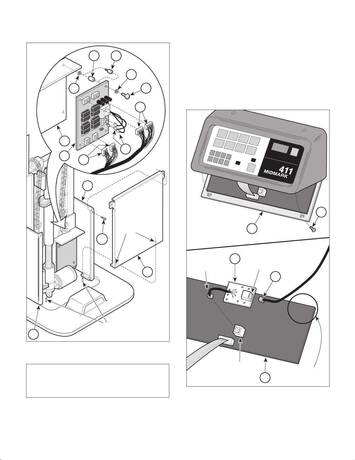
(1) Install four new standoffs (11) on brace (10) by
installing standoffs into original mounting holes
for interface board.
(2) Install interface board (5) on standoffs (11) and
secure with four starwashers (8) and new
screws (7).
(3) Connect three wires (6) to terminals of interface
board (5).
(4) Connect four wire harnesses (4) to connectors
of interface board (5).
(5) Install back lower shroud (2) on L.H. and R.H.
support channels (3) and secure with two
screws (1), making sure locator pins are
inserted thru locator holes of back lower
shroud.
© Midmark Corporation 1995 SF-1492 Page 4-3 Printed in U.S.A.
Page 30
SECTION IV
8
7
9
11
8
4
5
4
6
10
Return To Table Of Contents
MAINTENANCE / SERVICE
(6) Remove two screws (1, Figure 4-4) and lower
the console cover (2) down.
(7) Check Midmark part number on PC logic
board (3). If part number is
Revision A
adapter as described in steps 8 thru 10. If part
number is
not install adapter; go to step 11.
5
or
015-0460-00 Revision B
015-0460-00 Revision C or later
1
2
3
7
4
8
6
015-0460-00
, install
, do
3
LOCA TOR
HOLES
1
2
3
Figure 4-3. Interface Board Removal / Installation
LOCA TOR
PINS
MA302400
ADAPTER
BOARD
PLUG
5
2
ADAPTER
BOARD
PORT
4
015-0460-00
REVISION "X"
1
NOTE
The console cover is hinged. After removing two
screws (3), the front edge of the console cover may
be lowered.
© Midmark Corporation 1995 SF-1492 Page 4-4 Printed in U.S.A.
HAND
CONTROL
PORT
Figure 4-4. Adapter Board Installation
3
MIDMARK
PART NUMBER
MA302500
Page 31

SECTION IV
8
7
8
4
5
4
6
11
9
Return To Table Of Contents
MAINTENANCE / SERVICE
(8) Disconnect modular cord (4) from hand control
port of PC logic board (3).
NOTE
Adapter board is supplied with the interface board kit.
(9) Connect plug of adapter board (5) into hand
control port of PC logic board (3).
(10) Plug modular cord (4) into port of adapter
board (5).
(11) Close console cover (2) and secure in this
position with two screws (1).
(12) If removed, install shrouds (Refer to
para 4.2 or 4.3).
(13) Plug table power cord into wall outlet.
4.5 Interface Board Removal / Installation
(Later Units)
NOTE
This procedure applies to units with Serial Number
AV-2218 Thru Present and DJ-1000 Thru Present
with the following exceptions: AV-2229, AV-2231,
AV-2236, AV-2238, AV-2244, AV-2247, and AV-
2248.
(4) Remove two screws (1, Figure 4-5) and back
lower shroud (2) from L.H. and R.H support
channels (3).
(5) Tag and disconnect four wire harnesses (4)
from connectors of interface board (5).
3
A. Removal
(1) If possible, raise TABLE UP function all the way
up.
WARNING
Always disconnect the power cord
from the wall outlet before removing
any of the table's covers / shrouds or making any
repairs to prevent the possibility of electrical
shock. Failure to comply with these instructions
could result in severe personal injury or death.
(2) Unplug table power cord from wall outlet.
(3) If TABLE UP function cannot be raised all the
way up, remove shrouds (Refer to
para 4.2 or 4.3).
LOCAT OR
HOLES
1
2
LOCAT OR
3
Figure 4-5. Interface Board Removal / Installation
PINS
MA302600
© Midmark Corporation 1995 SF-1492
Page 4-5
Printed in U.S.A.
Page 32

SECTION IV
7
9
8
5
6
11
10
Return To Table Of Contents
MAINTENANCE / SERVICE
(6) Tag and disconnect three wires (6) from
terminals of interface board (5).
(7) Remove four screws (7), eight starwashers (8),
and interface board (5) from standoffs (9).
B. Installation
(1) Install interface board (5) on standoffs (9) and
secure with eight starwashers (8) and
screws (7).
(2) Connect three wires (6) to terminals of interface
board (5).
1
2
3
5
6
7
4
8
(3) Connect four wire harnesses (4) to connectors
of interface board (5).
3
2
(4) Install back lower shroud (2) on L.H. and R.H.
support channels (3) and secure with two
screws (1), making sure locator pins are
inserted thru locator holes of back lower
shroud.
(5) If removed, install shrouds (Refer to para 4.2 or
4.3).
(6) Plug table power cord into wall outlet.
HAND
CONTROL
PORT
1
4.6 PC Logic Board Removal / Installation
A. Removal
WARNING
Always disconnect the power cord
from the wall outlet before removing
any of the table's covers / shrouds or making any
repairs to prevent the possibility of electrical
shock. Failure to comply with these instructions
could result in severe personal injury or death.
(1) Unplug table power cord from wall outlet.
(2) Disconnect hand control coil cord (1, Figure 4-
6) from hand control port of PC logic board (2).
NOTE
The console cover is hinged. After removing two
screws, console cover should be able to be lowered.
Figure 4-6. PC Logic Board Removal / Installation
(3) Remove two screws (3) and then lower console
cover (4).
(4) Tag and disconnect four transmitter wires (5)
from PC logic board (2).
(5) Tag and disconnect four receiver wires (6) from
PC logic board (2).
4
2
MA302700
© Midmark Corporation 1995 SF-1492 Page 4-6 Printed in U.S.A.
Page 33

SECTION IV
Return To Table Of Contents
MAINTENANCE / SERVICE
(6) Disconnect ribbon connector (7), modular cord
(8), and wire harness (9) from PC logic
board (2).
(7) Remove four screws (10), starwashers (11),
and PC logic board (2) from console cover (4).
B. Installation
(1) Install PC logic board (2) on console cover (4)
and secure with four starwashers (11) and
screws (10).
(2) Connect wire harness (9), modular cord (8),
and ribbon connector (7) to PC logic board (2).
(3) Connect four receiver wires (6) to PC logic
board (2).
(4) Connect four transmitter wires (5) to PC logic
board (2).
(5) Close console cover (4) and secure in this
position with two screws (3).
(6) Connect hand control coil cord (1) to hand
control port of PC logic board (2).
4
2
RIBBON
CABLE
3
1
5
2
5
3
6
4
7
8
1
RIBBON
7
8
6
CABLE
9
10
11
5
(7) Plug table power cord into wall outlet.
4.7 Program Panel or Program Panel
Interface Board Removal / Installation
A. Removal
WARNING
Always disconnect the power cord
from the wall outlet before removing
any of the table's covers / shrouds or making any
repairs to prevent the possibility of electrical
shock. Failure to comply with these instructions
could result in severe personal injury or death.
(1) Unplug table power cord from wall outlet.
(2) Remove four screws (1, Figure 4-7) and bezel
(2) from console weldment (3).
(3) Remove six screws (4) and partially remove
program panel (5) from console weldment (3).
RIBBON
CABLE
MA302800
Figure 4-7. Program Panel or Program Panel
Interface Board Removal / Installation
(4) Disconnect ribbon cable of program panel
interface board (6) from PC logic board (7).
(5) Disconnect two wires (8) from program panel
interface board (6) and then remove program
panel (5) from table.
(6) Disconnect ribbon cable of program panel (5)
from program panel interface board (6).
© Midmark Corporation 1995 SF-1492 Page 4-7 Printed in U.S.A.
Page 34

SECTION IV
Return To Table Of Contents
MAINTENANCE / SERVICE
NOTE
Newer program panel interface boards do not have
spacers (11) and lockwashers (10).
(7) Remove three locknuts (9) and program panel
interface board (6) from program panel (5) or
remove three nuts (9), lockwashers (10),
program panel interface board (6), and spacers
(11) from program panel (5).
B. Installation
NOTE
If replacing an old style program panel interface
board (does not have standoffs) with a new style
program panel interface board (has standoffs),
discard spacers; they are not necessary.
(1) Install program panel interface board (6) on
program panel (5) and secure with three
locknuts (9) or three spacers (11), lockwashers
(10) and nuts (9).
(2) Connect ribbon cable of program panel (5) to
program panel interface board (6).
(3) Connect two wires (8) to program panel inter-
face board (6).
(4) Connect ribbon cable of program panel inter-
face board (6) to PC logic board (7).
(5) Install program panel (5) on console weldment
(3) and secure with six screws (4).
(6) Install bezel (2) on console weldment (3) and
secure with four screws (1).
6
5
2
3
SLOT
RIBBON
CONNECTOR
4
7
"A"
SLOT
"B"
1
MA302900
Figure 4-8. Hand Control Panel or Hand Control
Board Removal / Installation
(2) Remove two screws (2) and top end cap (3)
from hand control tube (4).
(3) Remove spacer plate (5) from hand control
tube (4).
(4) Remove hand control panel (6) and hand
control board (7) as an assembly from hand
control tube (4).
8
(7) Plug table power cord into wall outlet.
4.8 Hand Control Panel or Hand Control
Board Removal / Installation
A. Removal
(1) Disconnect coil cord (1, Figure 4-8) from hand
control.
© Midmark Corporation 1995 SF-1492 Page 4-8 Printed in U.S.A.
(5) Disconnect ribbon connector of hand control
panel (6) from hand control board (7).
B. Installation
(1) Connect ribbon connector of hand control panel
(6) to hand control board (7).
(2) Make sure fishpaper insulator (8) is on the
bottom of hand control tube (4).
Page 35

(3) Simultaneously, slide hand control panel (6)
Return To Table Of Contents
into slot A and hand control board (7) into slot B
of hand control tube (4).
SECTION IV
MAINTENANCE / SERVICE
(4) Install spacer plate (5) into slot B of hand
control tube (4).
(5) Install top end cap (3) on hand control tube (4)
and secure with two screws (2).
(6) Connect coil cord (1) to hand control.
4.9 Pan Safety Limit Switch Removal /
Installation
A. Removal
WARNING
Always disconnect the power cord
from the wall outlet before removing
any of the table's covers / shrouds or making any
repairs to prevent the possibility of electrical
shock. Failure to comply with these instructions
could result in severe personal injury or death.
(1) Unplug table power cord from wall outlet.
(2) Remove upholstered seat (1, Figure 4-9) from
seat board assembly (2).
1
2
17
10
11
12
13
16
7
14
15
9
5
8
NOTE
Removal of latest version of stirrup housing is
shown. Removal of early versions of stirrup housing
is similar.
(3) Remove one screw (3), two screws (4),
lockwashers (5), and stirrup housing (6) from
each side of seat weldment (7).
(4) Remove four screws (8), lockwashers (9), and
seat board assembly (2) from seat weldment (7).
NOTE
If necessary, install a jumper wire across two wires
(10) so FOOT DOWN function may be lowered.
(5) Run FOOT DOWN function all the way down.
6
PAN HOLDER
ASSEMBLY
Figure 4-9. Pan Safety Limit Switch Removal /
(6) Disconnect two wires (10) from pan safety limit
switch (11).
(7) Remove two screws (12), lockwashers (13),
washers (14) and switch bracket (15) from seat
weldment (7).
(8) Remove two nuts (16), screws (17), and pan
safety limit switch (11) from switch bracket (15).
3
Installation / Adjustment
ACCESS
HOLES
MA303000
4
© Midmark Corporation 1995 SF-1492 Page 4-9 Printed in U.S.A.
Page 36

SECTION IV
Return To Table Of Contents
MAINTENANCE / SERVICE
B. Installation
(1) Install pan safety limit switch (11) on switch
bracket (15) and secure with two screws (17)
and nuts (16).
(2) Install switch bracket (15) on seat weldment (7)
and secure with two washers (14), lockwashers
(13), and screws (12). Do not tighten screws
(12) fully.
(3) Push pan holder assembly inward until it locks
into its fully stowed position.
(4) Connect one wire (10) to N.O. terminal of pan
safety limit switch (11) and other wire (10) to
COM. terminal of pan safety limit switch.
EQUIPMENT ALERT
Adjust pan safety limit switch so only trip
arm of limit switch makes contact with pan
holder assembly when it is closed; otherwise damage to limit switch could occur from pan holder
assembly "slamming" into the limit switch.
4.10 Typical Capacitor Removal / Installation
A. Removal
(1) If possible, raise TABLE UP function all the way
up.
WARNING
Always disconnect the power cord
from the wall outlet before removing
any of the table's covers / shrouds or making any
repairs to prevent the possibility of electrical
shock. Failure to comply with these instructions
could result in severe personal injury or death.
(2) Unplug table power cord from wall outlet.
(3) Remove shrouds as necessary (Refer to para
4.2 or 4.3).
(4) Remove two screws (1, Figure 4-10) and back
lower shroud (2) from R.H. and L.H. support
channels (3).
(5) Slide switch bracket (15) toward rear panel of
pan holder assembly until trip arm of pan safety
limit switch (11) is firmly tripped by pan holder
assembly. Tighten two screws (12).
(6) Install seat board assembly (2) on seat
weldment (7) and secure with four lockwashers
(9) and screws (8).
NOTE
Installation of latest version of stirrup housing is
shown. Installation of early versions of stirrup
housing is similar.
(7) Install one stirrup housing (6) on each side of
seat weldment (7) and secure with two
lockwashers (5), screws (4), and screw (3).
(8) Install upholstered seat (1) on seat board
assembly (2).
(9) Plug table power cord into wall outlet.
(5) If necessary, cut any cable ties securing wires
to capacitor being removed.
(6) Using a screwdriver, pry tab of capacitor
mounting bracket (4) upward and remove
capacitor (5) from capacitor mounting bracket.
(7) Remove capacitor cap (6) from capacitor (5).
WARNING
A capacitor contains stored electricity.
Never touch terminals of a capacitor,
even if power has been shut off or disconnected.
Always discharge capacitor before touching
capacitor terminals or wires. Failure to comply
with these instruction could result in serious
personal injury or death.
(8) Discharge capacitor (5).
(9) Disconnect two wires (7) from terminals of
capacitor (5).
© Midmark Corporation 1995 SF-1492 Page 4-10 Printed in U.S.A.
Page 37

SECTION IV
Return To Table Of Contents
MAINTENANCE / SERVICE
4
LOCATION
VIEW
NOTE: The foot and
back capacitors may
be switched on some
units. Check the wire
colors of these capac-
itors to determine
foot or back capacitor
location. Red wires
are connected to the
back capacitor and
the yellow wires are
connected to the
foot capacitor.
TAB
CATCH
5
B. Installation
(1) Connect two wires (7) to terminals of capaci-
tor (5).
(2) Install capacitor cap (6) on capacitor (5).
7
(3) Position bottom of capacitor (5) on capacitor
mounting bracket (4) and then push the top of
6
BACK OR FOOT
CAPACITOR
(See Note)
BASE
CAPACITOR
TILT
CAPACITOR
the capacitor in. Using a screwdriver, force tab
of capacitor mounting bracket (4) down over
catch.
(4) If removed, install cable ties to secure wires to
capacitor (5).
(5) Install back lower shroud (2) on R.H. and L.H.
support channels (3) and secure with two
screws (1), making sure locator pins are
inserted thru locator holes of back lower
shroud.
(6) If removed, install shrouds (Refer to para 4.2 or 4.3).
(7) Plug table power cord into outlet.
4.11 Back Actuator Receiver and Transmitter Removal / Installation
NOTE
The back receiver and back transmitter are a
matched set and must be replaced as a set.
LOCATOR
HOLES
1
3
2
LOCATOR
3
Figure 4-10. Typical Capacitor
Removal / Installation
PINS
MA303100
A. Removal
(1) If possible, raise BACK UP function all the way
up.
WARNING
Always disconnect the power cord
from the wall outlet before removing
any of the table's covers / shrouds or making any
repairs to prevent the possibility of electrical
shock. Failure to comply with these instructions
could result in severe personal injury or death.
(2) Unplug table power cord from wall outlet.
(3) Remove four screws (1, Figure 4-11),
lockwashers (2), and backrest assembly (3)
from back weldment (4).
© Midmark Corporation 1995 SF-1492 Rev. 4/97 Page 4-11 Printed in U.S.A.
Page 38

SECTION IV
XX
IDENTIFICATION
NUMBER
10
5
CABLE
TIES
TAPE OR
PENCIL MARK
CABLE
TIES
3/16" TO 5/16"
(4.7 TO 7.9 mm)
ALIGN BACK
TRANSMITTER
WITH SOUND
TUBE OF BACK
RECEIVER
Return To Table Of Contents
MAINTENANCE / SERVICE
(4) Use pencil or tape to mark positions of back
receiver (5) and back transmitter (6) on back
actuator (7).
(5) Disconnect cable (8) from back transmitter (6).
(6) Cut two cable ties securing back transmitter (6)
to shaft of back actuator (7) and remove back
transmitter.
(7) Disconnect cable (9) from back receiver (5).
(8) Cut three cable ties securing back receiver (5)
to back actuator (7) and remove back receiver.
(9) Remove sound tube (10) from back re-
ceiver (5).
B. Installation
NOTE
If you become uncertain as to which part is the
receiver and which part is the transmitter, remove
the receiver or transmitter from its black plastic
mounting bracket and check its identification number
(located on side of receiver or transmitter). An
EFRRTB40K2 number indicates the part is a receiver
while an EFROTB40K2 number indicates the part is
a transmitter.
5
6
1
2
(1) Install sound tube (10) on back receiver (5).
(2) Align back receiver (5) with mark (made during
removal) on back actuator (7) and secure in
this position with three cable ties.
(3) Connect cable (9) to back receiver (5).
(4) Align back transmitter (6) with mark (made
during removal) on back actuator (7) and
secure in this position with two cable ties.
(5) Connect cable (8) to back transmitter (6).
(6) Carefully run BACK UP function all the way up
and then run BACK DOWN function all the way
down, while watching to make sure the back
receiver (5) or back transmitter (6) does not
come into contact with anything.
4
9
3
5
6
7
8
MA303200
Figure 4-11. Back Actuator Receiver and
Transmitter Removal / Installation
© Midmark Corporation 1995 SF-1492 Page 4-12 Printed in U.S.A.
Page 39

(7) If it is determined that contact will occur, adjust
Return To Table Of Contents
both the back receiver (5) and / or back transmitter (6) as determined necessary to correct
situation.
(8) Lower BACK DOWN function all the way down.
EQUIPMENT ALERT
The alignment of the back receiver and
back transmitter is critical to the programming function. Failure to do so could result in
programming operation malfunction.
13
SECTION IV
MAINTENANCE / SERVICE
PILOT
HOLE
14
1/8"
DRILL
BIT
6
(9) Slide back transmitter (6) up or down shaft of
back actuator (7) until back transmitter is 3/16
to 5/16 in. (4.7 to 7.9 mm) from sound
tube (10). Then rotate back transmitter (6) until
it is directly aligned with sound tube (10) of
back receiver (5).
NOTE
Because the back receiver and back transmitter may
not be returned exactly to the same position, have
the operator check the integrity of the programmed
positions.
(10) Install backrest assembly (3) on back weldment
(4) and secure with four lockwashers (2) and
screws (1).
4.12 Back Actuator Removal / Installation
A. Removal
(1) If possible, lower BACK DOWN function all the
way down.
(2) Remove back actuator transmitter and receiver
(Refer to para 4.11).
CABLE
TIE
3
12
7
8
1
10
7
4
2
5
7
(3) Cut cable tie securing three wires (1, Figure 4-
12) and receiver cable (2) to shaft of back
actuator (3).
(4) Tag and disconnect three wires (1) from
actuator wires (4).
(5) Cut cable tie securing transmitter cable (5) to
shaft of back actuator (3).
© Midmark Corporation 1995 SF-1492 Page 4-13 Printed in U.S.A.
9
CABLE
TIE
7
11
MA303300
Figure 4-12. Back Actuator Removal / Installation
Page 40

SECTION IV
Return To Table Of Contents
MAINTENANCE / SERVICE
(6) While supporting back weldment (6), remove
four e-rings (7), two clevis pins (8 and 9), and
back actuator (3) from brackets (10 and 11).
B. Installation
(1) If installing new back actuator (3), transfer
marks for back receiver and back transmitter
from old back actuator to new back actuator.
(2) Install back actuator (3) on brackets (10 and
11) and secure with two clevis pins (8 and 9)
and four e-rings (7).
(3) Connect three actuator wires (4) to wires (1).
(4) Secure three wires (1) and receiver cable (2) to
shaft of back actuator (3) with a cable tie.
(5) Lower BACK DOWN function all the way down
(until back actuator can be heard free wheel-
ing).
(6) Observe. Back weldment (6) should be parallel
with seat section (12). If back weldment
parallel with seat section, go to step 11. If back
weldment
step 7.
is not
parallel with seat section, go to
(13) Secure clevis (13) in position by installing roll
pin (14) in pilot hole.
(14) Secure cable (5) to clevis (13) with a cable tie.
(15) Install back actuator transmitter and receiver
(Refer to para 4.11).
4.13 Foot Actuator Receiver and Transmitter Removal / Installation
NOTE
The foot receiver and foot transmitter are a matched
set and must be replaced as a set.
A. Removal
(1) If possible, raise FOOT UP function all the way
up.
WARNING
Always disconnect the power cord
from the wall outlet before removing
is
any of the table's covers / shrouds or making any
repairs to prevent the possibility of electrical
shock. Failure to comply with these instructions
could result in severe personal injury or death.
(7) While supporting back weldment (6), remove
clevis pin (9) securing clevis (13) to
bracket (11).
(8) Screw clevis (13) inward or outward as deter-
mined necessary in step 6.
(9) Connect clevis (13) to bracket (11) with clevis
pin (9).
(10) Repeat steps 5 thru 10 until back weldment (6)
is parallel with seat section (12).
(11) Install two e-rings (7) on clevis pin (9).
(12) Using pilot hole as a guide, drill hole thru clevis
(13) with a 1/8 in. drill bit.
EQUIPMENT ALERT
Carefully drive in roll pin. Using excessive
force could bend rod, resulting in noisy
operation.
(2) Unplug table power cord from wall outlet.
(3) Remove four screws (1, Figure 4-13), and
plastic foot cover (2) from foot extension (3).
(4) Use pencil or tape to mark positions of foot
receiver (4) and foot transmitter (5) on shaft of
foot actuator (6).
(5) Disconnect cable (7) from foot transmitter (5).
(6) Cut two cable ties securing foot transmitter (5)
to shaft of foot actuator (6) and remove foot
transmitter.
(7) Disconnect cable (8) from foot receiver (4).
(8) Cut three cable ties securing foot receiver (4) to
foot actuator (6) and remove foot receiver.
(9) Remove sound tube (9) from foot receiver (4).
© Midmark Corporation 1995 SF-1492 Page 4-14 Printed in U.S.A.
Page 41

SECTION IV
NUMBER
9
XXXRXXXXXX
IDENTIFICA TION
4
CABLE
TIES
TAPE OR
PENCIL MARK
CABLE
TIES
3/16" TO 5/16"
(4.7 TO 7.9 mm)
ALIGN FOOT
TRANSMITTER
WITH SOUND
TUBE OF FOOT
RECEIVER
Return To Table Of Contents
MAINTENANCE / SERVICE
B. Installation
NOTE
If you become uncertain as to which part is the
receiver and which part is the transmitter, remove
the receiver or transmitter from its black plastic
mounting bracket and check its identification number
(located on side of receiver or transmitter). An
EFRRTB40K2 number indicates the part is a receiver
4
5
while an EFROTB40K2 number indicates the part is
a transmitter.
(1) Install sound tube (9) on foot receiver (4).
(2) Align foot receiver (4) with mark (made during
removal) on foot actuator (6) and secure in this
position with three cable ties.
(3) Connect cable (8) to foot receiver (4).
(4) Align foot transmitter (5) with mark (made
during removal) on foot actuator (6) and secure
in this position with two cable ties.
7
5
4
9
8
6
3
2
1
Figure 4-13. Foot Actuator Receiver and
Transmitter Removal / Installation
(5) Connect cable (7) to foot transmitter (5).
(6) Carefully run FOOT UP function all the way up
and then run FOOT DOWN function all the way
down, while watching to make sure the foot
receiver (4) or foot transmitter (5) does not
come into contact with anything.
(7) If it is determined that contact will occur, adjust
both the foot receiver (4) and / or foot transmit-
ter (5) as determined necessary to correct
situation.
(8) Lower FOOT DOWN function all the way down.
EQUIPMENT ALERT
The alignment of the foot receiver and
foot transmitter is critical to the programming function. Failure to do so could result in
programming operation malfunction.
(9) Slide foot transmitter (5) up or down shaft of
foot actuator (6) until foot transmitter is 3/16 to
5/16 in. (4.7 to 7.9 mm) from sound tube (9).
Then rotate foot transmitter (5) until it is directly
aligned with sound tube (9) of back receiver (4).
MA303400
© Midmark Corporation 1995 SF-1492 Page 4-15 Printed in U.S.A.
Page 42

SECTION IV
Return To Table Of Contents
MAINTENANCE / SERVICE
NOTE
Because the foot receiver and foot transmitter may
not be returned exactly to the same position, have
the operator check the integrity of the programmed
positions.
(10) Install plastic foot cover (2) on foot extension
(3) and secure with four screws (1).
4.14 Foot Actuator Removal / Installation
(3) Install foot actuator (3) on foot extension (6)
and secure with three screws (10).
(4) Connect clevis (14) to bracket (9) and secure
with clevis pin (8).
(5) Connect three actuator wires (1) to three
wires (4).
(6) Secure three actuator wires (1) to shaft of foot
actuator (3) with cable ties.
A. Removal
(1) If possible, raise FOOT UP function all the way
up.
(2) Remove foot actuator transmitter and receiver
(Refer to para 4.13).
(3) Cut cable ties securing three actuator wires (1,
Figure 4-14) and receiver cable (2) to shaft of
foot actuator (3).
(4) Tag and disconnect three actuator wires (1)
from three wires (4).
(5) Cut cable tie securing transmitter cable (5) to
shaft of foot actuator (3).
(6) While supporting foot extension (6), remove
two e-rings (7), clevis pin (8) securing shaft of
foot actuator (3) to bracket (9).
(7) While supporting foot extension (6), remove
three screws (10) and foot actuator (3) from
foot extension. Lower foot extension.
(8) Remove two e-rings (11), clevis pin (12), and
actuator hitch (13) from foot actuator (3).
B. Installation
(1) If installing new foot actuator (3), transfer marks
for foot receiver and foot transmitter from old
foot actuator to new foot actuator.
(7) Lower FOOT DOWN function all the way down
(until foot actuator can be heard free wheeling).
(8) Observe. Foot extension (6) should be parallel
with seat section (15). If foot extension
parallel with seat section, go to step 13. If foot
extension
step 9.
(9) While supporting foot extension (6), remove
clevis pin (8) securing clevis (14) to
bracket (9).
(10) Screw clevis (14) inward or outward as deter-
mined necessary in step 7.
(11) Connect clevis (14) to bracket (9) with clevis
pin (8).
(12) Repeat steps 7 thru 11 until back foot extension
(6) is parallel with seat section (15).
(13) Install two e-rings (7) on clevis pin (8).
(14) Using pilot hole as a guide, drill hole thru clevis
(14) with a 1/8 in. drill bit.
is not
parallel with seat section, go to
is
EQUIPMENT ALERT
Carefully drive in roll pin. Using excessive
force could bend rod, resulting in noisy
operation.
(15) Secure clevis (14) in position by installing roll
pin (16) in pilot hole.
(2) Install actuator hitch (13) on foot actuator (3)
and secure with clevis pin (12) and two
e-rings (11).
© Midmark Corporation 1995 SF-1492 Page 4-16 Printed in U.S.A.
(16) Secure cable (5) to clevis (14) with a cable tie.
(17) Install foot actuator transmitter and receiver
(Refer to para 4.13).
Page 43

1/8"
DRILL
BIT
PILOT
HOLE
14
16
6
A
3
13
11
12
11
10
15
CABLE
TIE
3
9
CABLE
TIE
7
CABLE
TIE
1
4
2
5
7
8
A
Return To Table Of Contents
SECTION IV
MAINTENANCE / SERVICE
Figure 4-14. Foot Actuator Removal / Installation
MA303500
© Midmark Corporation 1995 SF-1492 Page 4-17 Printed in U.S.A.
Page 44

SECTION IV
Return To Table Of Contents
MAINTENANCE / SERVICE
4.15 Tilt Actuator Receiver and Transmitter Removal / Installation
NOTE
The tilt receiver and tilt transmitter are a matched set
and must be replaced as a set.
A. Removal
(1) If possible, raise TABLE UP and FOOT UP
functions all the way up.
WARNING
Always disconnect the power cord
from the wall outlet before removing
any of the table's covers / shrouds or making any
repairs to prevent the possibility of electrical
shock. Failure to comply with these instructions
could result in severe personal injury or death.
(2) Unplug table power cord from wall outlet.
(3) Remove shrouds as necessary (Refer to para
4.2 or 4.3).
TAPE OR
PENCIL MARK
2
CABLE
TIES
3/16" TO 5/16"
(4.7 TO 7.9 mm)
CABLE
TIES
1
ALIGN TILT
TRANSMITTER
WITH SOUND
TUBE OF TILT
RECEIVER
2
XXXRXXXXXX
IDENTIFICATION
NUMBER
(4) Use pencil or tape to mark positions of tilt
receiver (1, Figure 4-15) and tilt transmitter (2)
on shaft of tilt actuator (3).
(5) Disconnect cable (4) from tilt transmitter (2).
(6) Cut two cable ties securing tilt transmitter (2) to
shaft of tilt actuator (3) and remove tilt transmit-
ter.
(7) Disconnect cable (5) from tilt receiver (1).
(8) Cut three cable ties securing tilt receiver (1) to
tilt actuator (3) and remove tilt receiver.
(9) Remove sound tube (6) from tilt receiver (1).
2
3
1
5
Figure 4-15. Tilt Actuator Receiver and
Transmitter Removal / Installation
4
6
MA303600
© Midmark Corporation 1995 SF-1492
Page 4-18
Printed in U.S.A.
Page 45

B. Installation
Return To Table Of Contents
NOTE
If you become uncertain as to which part is the
receiver and which part is the transmitter, remove
the receiver or transmitter from its black plastic
mounting bracket and check its identification number
(located on side of receiver or transmitter). An
EFRRTB40K2 number indicates the part is a receiver
while an EFROTB40K2 number indicates the part is
a transmitter.
SECTION IV
MAINTENANCE / SERVICE
NOTE
Because the tilt receiver and tilt transmitter may not
be returned exactly to the same position, have the
operator check the integrity of the programmed
positions.
(10) Install shrouds as necessary (Refer to para 4.2
or 4.3).
(11) Plug table power cord into wall outlet.
(1) Install sound tube (6) on tilt receiver (1).
(2) Align tilt receiver (1) with mark (made during
removal) on tilt actuator (3) and secure in this
position with three cable ties.
(3) Connect cable (5) to tilt receiver (1).
(4) Align tilt transmitter (2) with mark (made during
removal) on tilt actuator (3) and secure in this
position with two cable ties.
(5) Connect cable (4) to tilt transmitter (2).
(6) Carefully run TILT UP function all the way up
and then run TILT DOWN function all the way
down, while watching to make sure the tilt
receiver (1) or tilt transmitter (2) does not come
into contact with anything.
(7) If it is determined that contact will occur, adjust
both the tilt receiver (1) and / or tilt transmitter
(2) as determined necessary to correct situa-
tion.
(8) Lower TILT DOWN function all the way down.
EQUIPMENT ALERT
The alignment of the tilt receiver and
tilt transmitter is critical to the programming function. Failure to do so could result in
programming operation malfunction.
4.16 Tilt Actuator Removal / Installation
A. Removal
(1) Remove tilt actuator transmitter and receiver
(Refer to para 4.15).
(2) Cut cable ties securing three wires (1, Figure 4-
16) to tilt actuator (2).
(3) Tag and disconnect three wires (1) from three
actuator wires (3).
(4) Cut two cable ties securing transmitter cable (4)
to shaft of tilt actuator (2).
(5) While supporting foot end of table top, remove
two e-rings (5) and clevis pin (6) securing shaft
of tilt actuator (2) to bracket (7).
(6) Lower tilt actuator (2) down out of way; then
lower foot end of table top downward until it is
resting on inner member weldment (8).
NOTE
Clevis pin can only be removed in one direction as
shown in the illustration.
(7) Remove two e-rings (9), clevis pin (10), and tilt
actuator (2) from bracket (11).
B. Installation
(9) Slide tilt transmitter (2) up or down shaft of tilt
actuator (3) until tilt transmitter is 3/16 to 5/16
in. (4.7 to 7.9 mm) from sound tube (6). Then
rotate tilt transmitter (2) until it is directly aligned
with sound tube (6) of tilt receiver (1).
© Midmark Corporation 1995 SF-1492 Page 4-19 Printed in U.S.A.
(1) If installing new tilt actuator (2), transfer marks
for tilt receiver and tilt transmitter from old tilt
actuator to new tilt actuator.
Page 46

SECTION IV
Return To Table Of Contents
MAINTENANCE / SERVICE
6
(2) Install tilt actuator (2) on bracket (11) and
secure with clevis pin (10) and two e-rings (9).
5
CABLE
2
CABLE
TIE
3
1
TIE
5
7
11
(3) Connect three actuator wires (3) to three
wires (1).
(4) While lifting up on foot end of table top, connect
shaft of tilt actuator (2) to bracket (7) with clevis
pin (6) and two e-rings (5).
4
(5) Secure three wires (1) to tilt actuator (2) with a
cable tie.
(6) Secure cable (4) to shaft of tilt actuator (2) with
cable ties.
(7) Install tilt actuator transmitter and receiver
(Refer to para 4.15).
4.17 Base Actuator Receiver and Trans-
10
9
8
NOTE
The base receiver and base transmitter are a
matched set and must be replaced as a set.
A. Removal
mitter Removal / Installation
MA303700
Figure 4-16 Tilt Actuator Removal / Installation
(1) If possible, raise TABLE UP and BACK UP
functions all the way up.
WARNING
Always disconnect the power cord
from the wall outlet before removing
any of the table's covers / shrouds or making any
repairs to prevent the possibility of electrical
shock. Failure to comply with these instructions
could result in severe personal injury or death.
(2) Unplug table power cord from wall outlet.
(3) Remove shrouds as necessary (Refer to para
4.2 or 4.3).
(4) Remove two screws (1, Figure 4-17) and rear
lower shroud (2) from R.H. and L.H. support
channels (3).
(5) Use pencil or tape to mark positions of base
receiver (4) and base transmitter (5) on shaft of
base actuator (6).
© Midmark Corporation 1995 SF-1492
Page 4-20
Printed in U.S.A.
Page 47

SECTION IV
TAPE OR
PENCIL MARK
XXXRXXXXXX
IDENTIFICATION
NUMBER
5
3/16" TO 5/16"
(4.7 TO 7.9 mm)
ALIGN BASE
TRANSMITTER
WITH SOUND
TUBE OF BASE
RECEIVER
CABLE
TIES
CABLE
TIES
6
4
5
Return To Table Of Contents
MAINTENANCE / SERVICE
(6) Disconnect cable (7) from base transmitter (5).
(7) Cut two cable ties securing base transmitter (5)
to shaft of base actuator (6) and remove base
transmitter.
(8) Disconnect cable (8) from base receiver (4).
(9) Cut three cable ties securing base receiver (4)
to base actuator (6) and remove base receiver.
(10) Remove sound tube (9) from base receiver (4).
B. Installation
NOTE
If you become uncertain as to which part is the
receiver and which part is the transmitter, remove
the receiver or transmitter from its black plastic
mounting bracket and check its identification number
(located on side of receiver or transmitter). An
EFRRTB40K2 number indicates the part is a receiver
while an EFROTB40K2 number indicates the part is
a transmitter.
4
(1) Install sound tube (9) on base receiver (4).
7
(2) Align base receiver (4) with mark (made during
removal) on base actuator (6) and secure in
this position with three cable ties.
5
3
LOCAT OR
HOLES
1
3
(3) Connect cable (8) to base receiver (4).
(4) Align base transmitter (5) with mark (made
during removal) on base actuator (6) and
secure in this position with two cable ties.
(5) Connect cable (7) to base transmitter (5).
(6) Carefully run TABLE UP function all the way up
and then run TABLE DOWN function all the
9
2
way down, while watching to make sure the
base receiver (4) or base transmitter (5) does
not come into contact with anything.
(7) If it is determined that contact will occur, adjust
both the base receiver (4) and / or base trans-
mitter (5) as determined necessary to correct
8
LOCAT OR
PINS
MA303800
situation.
Figure 4-17. Base Actuator Receiver and
Transmitter Removal / Installation
© Midmark Corporation 1995 SF-1492
Page 4-21
Printed in U.S.A.
Page 48

SECTION IV
Return To Table Of Contents
MAINTENANCE / SERVICE
(8) Lower BASE DOWN function all the way down.
EQUIPMENT ALERT
The alignment of the base receiver and
base transmitter is critical to the programming function. Failure to do so could result in
programming operation malfunction.
(9) Slide base transmitter (5) up or down shaft of
base actuator (6) until base transmitter is 3/16
to 5/16 in. (4.7 to 7.9 mm) from sound tube (9).
Then rotate base transmitter (5) until it is
directly aligned with sound tube (9) of base
receiver (4).
NOTE
Because the base receiver and base transmitter may
not be returned exactly to the same position, have
the operator check the integrity of the programmed
positions.
(10) Install back lower shroud (2) on L.H. and R.H.
support channels (3) and secure with two
screws (1), making sure locator pins are
inserted thru locator holes of back lower
shroud.
(11) Install shrouds as necessary (Refer to para 4.2
or 4.3).
(12) Plug table power cord into wall outlet.
EQUIPMENT ALERT
Slowly and carefully lower base actuator
until table top is resting on supports. Do
not run base actuator until it is in a bind. Damage to
base actuator could result.
c. Lower TABLE DOWN function until weight
of table top (3) is resting on support bar.
(3) If support bar is not available, support table top
with supports as described in the following
substeps:
a. Run TABLE UP function to 3/4 full up
position.
b. Run TILT DOWN function all the way down,
FOOT UP function all the way up and
BACK DOWN function all the way down,
making table top (3) into a flat, horizontal
position.
c. Place supports under foot section and back
section of table top (3).
EQUIPMENT ALERT
Slowly and carefully lower base actuator
until table top is resting on supports. Do
not run base actuator until it is in a bind. Damage to
base actuator could result.
4.18 Base Actuator Removal / Installation
A. Removal
(1) Remove base actuator transmitter and receiver
(Refer to para 4.17).
(2) If support bar is going to be used to support
weight of table top, perform the following
substeps. Otherwise, go to step 3. See Table
1-2 for special tool.
a. Run TABLE UP function all the way up.
b. With TABLE UP function in full up position,
place support bar across top of R.H. and
L.H. supports (1, Figure 4-18). Slide
support bar under tilt bracket (2).
d. Lower TABLE DOWN function until weight
of table top (3) is resting on supports or
raise supports up against table top.
(4) Cut cable tie securing wires to base actua-
tor (4).
(5) Tag and disconnect three wires (5) from three
actuator wires (6).
(6) Disconnect wire harness (7) from base down
limit switch (8).
© Midmark Corporation 1995 SF-1492 Page 4-22 Printed in U.S.A.
Page 49

2
1
SUPPORT
BAR
FOOT
CABLE
TIE
4
5
6
7
8
11
9
10
9
12
Return To Table Of Contents
SECTION
SECTION IV
MAINTENANCE / SERVICE
3
BACK
SECTION
SUPPORTS
© Midmark Corporation 1995 SF-1492
Figure 4-18 Table Top Support
Page 4-23
MA303900
Printed in U.S.A.
Page 50

SECTION IV
6
6
10
7
4
5
9
8
Return To Table Of Contents
MAINTENANCE / SERVICE
DANGER
Make sure weight of table top is
securely supported, per step 2 or 3,
and table top will not fall when clevis pin (10) is
removed. Failure to do so will result in serious
injury or death to personnel.
NOTE
Depending on strength of gas spring(s), the table top
may raise when clevis pin is removed. This is an
indicator that the gas spring(s) are functioning well.
(7) Remove two e-rings (9), clevis pin (10), and
two spacers (11) securing shaft of base actuator (4) to bracket (12).
(8) Remove two screws (1, Figure 4-19) and front
lower shroud (2) from R.H. and L.H.
supports (3).
(9) Remove pin clip (4), clevis pin (5), and base
actuator (6) from bracket (7).
(10) Remove two screws (8), lockwashers (9), and
switch bracket assembly (10) from base
actuator (6).
LOCA TOR
PIN
LOCA TOR
HOLES
3
1
2
3
LOCA TOR
PIN
B. Installation
(1) If installing new base actuator (6, Figure 4-19),
transfer marks for base receiver and base
transmitter from old base actuator to new base
actuator.
(2) Install switch bracket assembly (10) on base
actuator (6) and secure with two lockwashers
(9), and screws (8).
(3) Install base actuator (6) on bracket (7) and
secure with clevis pin (5) and pin clip (4).
(4) Install front lower shroud (2) on L.H. and R.H.
support channels (3) and secure with two
screws (1), making sure locator pins are
inserted thru locator holes of front lower
shroud.
(5) Connect three actuator wires (6, Figure 4-18) to
three wires (5).
MA304000
Figure 4-19. Base Actuator Removal / Installation
© Midmark Corporation 1995 SF-1492 Page 4-24 Printed in U.S.A.
Page 51

SECTION IV
Return To Table Of Contents
MAINTENANCE / SERVICE
(6) Connect wire harness (7) to base down limit
switch (8).
NOTE
Depending on strength of gas spring(s), an assistant
may be required to help lower the table top slightly to
allow alignment of base actuator shaft with bracket.
(7) Raise or lower TABLE UP or TABLE DOWN
function as necessary to align shaft of base
actuator (4) with bracket (12).
(8) Secure shaft of base actuator (4) to bracket
(12) with two spacers (11), clevis pin (10), and
two e-rings (9).
(9) Raise TABLE UP function all the way up.
(10) Remove support bar from under tilt bracket (2)
or remove supports from under foot section
and back section of table top (3).
(11) Secure wires to base actuator (4) with a cable
tie.
(3) Remove two screws (1, Figure 4-20) and rear
lower shroud (2) from R.H. and L.H.
supports (3).
(4) Remove two screws (4) and front lower shroud
(5) from R.H. and L.H. supports (3).
(5) If support bar is going to be used to support
weight of table top, perform the following
substeps. Otherwise, go to step 6. See Table
1-2 for special tools.
a. Run TABLE UP function all the way up.
b. With TABLE UP function in full up position,
place support bar across top of R.H. and
L.H. supports (3). Slide support bar under
tilt bracket (6).
EQUIPMENT ALERT
Slowly and carefully lower base actuator
until table top is resting on supports. Do
not run base actuator until it is in a bind. Damage to
base actuator could result.
(12) Install base actuator transmitter and receiver
(Refer to para 4.17).
4.19 Gas Spring(s) Removal / Installation
A. Removal
WARNING
Always disconnect the power cord
from the wall outlet before removing
any of the table's covers / shrouds or making any
repairs to prevent the possibility of electrical
shock. Failure to comply with these instructions
could result in severe personal injury or death.
NOTE
The two special tools that are required to perform
this procedure are included in the repair kit.
(1) Unplug table power cord from wall outlet.
(2) Remove shrouds as necessary (Refer to para
4.2 or 4.3).
c. Lower TABLE DOWN function until weight
of table top (7) is resting on support bar.
(6) If support bar is not available, support table top
with supports as described in the following
substeps:
a. Run TABLE UP function to 3/4 full up
position.
b. Run TILT DOWN function all the way down,
FOOT UP function all the way up. and
BACK DOWN function all the way down,
making table top (7) into a flat, horizontal
position.
c. Place supports under foot section and back
section of table top (7).
© Midmark Corporation 1995 SF-1492 Page 4-25 Printed in U.S.A.
Page 52

SECTION IV
SUPPORT
BAR
1
2
3
6
4
5
11
9
10
8
8
12
Return To Table Of Contents
MAINTENANCE / SERVICE
7
FOOT
SECTION
BACK
SECTION
SUPPORTS
13
14
MA304100
Figure 4-20 Table Top Support
© Midmark Corporation 1995 SF-1492
Page 4-26
Printed in U.S.A.
Page 53

EQUIPMENT ALERT
Return To Table Of Contents
Slowly and carefully lower base actuator
until table top is resting on supports. Do
not run base actuator until it is in a bind. Damage to
base actuator could result.
SECTION IV
MAINTENANCE / SERVICE
(11) While pressing down on end of pry bar to
relieve pressure from clevis pin (2), remove pin
clip (3), clevis pin (2), and two spacers (4).
Then, slowly raise up on pry bar until gas
spring(s) (5) are fully extended and are no
longer under tension. Remove pry bar.
d. Lower TABLE DOWN function until weight
of table top (7) is resting on supports or
raise supports up against table top.
DANGER
Make sure weight of table top is
securely supported, per step 5 or 6,
and table top will not fall when clevis pin (10) is
removed. Failure to do so will result in serious
injury or death to personnel.
NOTE
Depending on strength of gas spring(s), the table top
may raise when clevis pin is removed. This is an
indicator that the gas spring(s) are functioning well.
(7) Remove two e-rings (8), spacers (9), and clevis
pin (10) which secures shaft of base actuator
(11) to bracket (12).
(8) Disconnect cable (13) from base transmit-
ter (14).
EQUIPMENT ALERT
Slowly and carefully lower base actuator
while holding shaft of base actuator
stationary, making sure base transmitter (14) does
not contact anything. Failure to do so could result in
damage to base transmitter.
(12) Remove pin clip (6), clevis pin (7), spacer(s)
(8), and gas spring(s) (5) from bracket (9).
B. Installation
(1) Install rod end of gas spring(s) (5, Figure 4-21)
on bracket (9) and secure with clevis pin (7),
spacer(s) (8), and pin clip (6).
(2) Insert slot of pry bar in cutout of middle mem-
ber assembly (1).
(3) While pressing down on end of pry bar to align
gas spring(s) (5) with bracket (10), install two
spacers (4), clevis pin (2), and pin clip (3) to
secure gas spring(s) to bracket. Remove pry
bar.
EQUIPMENT ALERT
Slowly and carefully raise base actuator
while holding shaft of base actuator
stationary, making sure base transmitter (14) does
not contact anything. Failure to do so could result in
damage to base transmitter.
(4) While holding shaft of base actuator (11, Figure
4-20) stationary (so it cannot rotate), raise
TABLE UP function until shaft of base actuator
is aligned with bracket (12).
(9) While holding shaft of base actuator (11)
stationary (so it cannot rotate), lower TABLE
DOWN function until base actuator is fully
retracted.
(10) Insert slot of pry bar in cutout of middle mem-
ber assembly (1, Figure 4-21). See Table 1-2
for special tool.
© Midmark Corporation 1995 SF-1492 Page 4-27 Printed in U.S.A.
NOTE
Depending on strength of gas spring(s), an assistant
may be required to help lower the table top slightly to
allow alignment of base actuator shaft with bracket.
(5) Secure shaft of base actuator (11) to bracket
(12) with two spacers (9), clevis pin (10), and
two e-rings (8).
(6) Raise TABLE UP function all the way up.
Page 54

SECTION IV
6
8
5
7
9
4
3
5
2
1
PRY
BAR
SLOT
CUTOUT
10
10
Return To Table Of Contents
MAINTENANCE / SERVICE
(7) Remove support bar from under tilt bracket (6)
or remove supports from under foot section
and back section of table top (7).
(8) Connect cable (13) to base transmitter (14).
(9) Install front lower shroud (5) on L.H. and R.H.
supports (3) and secure with two screws (4),
making sure locator pins are inserted thru
locator holes of front lower shroud.
(10) Install rear lower shroud (2) on L.H. and R.H.
supports (3) and secure with two screws (1),
making sure locator pins are inserted thru
locator holes of front lower shroud.
(11) Install shrouds as necessary (Refer to para 4.2
or 4.3).
(12) Plug table power cord into wall outlet.
Figure 4-21. Gas Spring(s) Removal / Installation
4.20 Base Down Limit Switch Removal /
Installation
A. Removal
(1) Raise TABLE UP function all the way up.
WARNING
Always disconnect the power cord
from the wall outlet before removing
any of the table's covers / shrouds or making any
repairs to prevent the possibility of electrical
shock. Failure to comply with these instructions
could result in severe personal injury or death.
(2) Unplug table power cord from wall outlet.
(3) Remove two screws (1, Figure 4-22) and rear
lower shroud (2) from R.H. and L.H.
supports (3).
MA304200
(4) Disconnect wire harness (4) from base down
limit switch (5).
© Midmark Corporation 1995 SF-1492
(5) Remove two nuts (6), lockwashers (7), screws
(8), and base down limit switch (5) from switch
bracket (9).
Page 4-28
Printed in U.S.A.
Page 55

SECTION IV
6
9
5
8
4
7
Return To Table Of Contents
MAINTENANCE / SERVICE
(2) Connect wire harness (4) to base down limit
switch (5).
C. Adjustment
(1) Plug table power cord into wall outlet.
(2) Raise TABLE UP function up at least 6 in.
(15.2 cm).
(3) Press AUTO RETURN "RETURN" button.
(4) Observe. The base actuator should begin to
lower. When the base actuator is almost
completely lowered, the base down limit switch
should be tripped, stopping the base actuator.
(5) If the base actuator does not stop running after
base actuator is completely lowered, loosen
two nuts (6) and slide base down limit switch
(5) upward approximately 1/16 in. (1.6 mm);
then tighten two nuts.
B. Installation
LOCAT OR
HOLES
1
3
2
LOCAT OR
PINS
3
Figure 4-22. Base Down Limit Switch
Removal / Installation
MA304300
NOTE
Install base down limit switch as low as possible on
switch bracket to start with.
(1) Install base down limit switch (5) on switch
bracket (9) and secure with two screws (8),
lockwashers (7), and nuts (6).
(6) If the base down limit switch (5) trips too early
so that the table top can be manually lowered
more than 1/2 in. (12.7 mm) after the base
down limit switch has been tripped, loosen two
nuts (6) and slide base down limit switch (5)
downward approximately 1/16 in. (1.6 mm);
then tighten two nuts.
(7) Repeat steps 2 thru 6 until the base down limit
switch (5) is adjusted properly.
(8) Install rear lower shroud (2) on L.H. and R.H.
supports (3) and secure with two screws (1),
making sure locator pins are inserted thru
locator holes of front lower shroud.
4.21 Typical Actuator Motor / Actuator
Brake Removal / Installation
A. Removal
(1) Remove malfunctioning actuator assembly:
Back actuator assembly (Refer to para 4.12).
Foot actuator assembly (Refer to para 4.14).
Tilt actuator assembly (Refer to para 4.16).
Base actuator assembly (Refer to para 4.18).
© Midmark Corporation 1995 SF-1492
Page 4-29
Printed in U.S.A.
Page 56

SECTION IV
Return To Table Of Contents
MAINTENANCE / SERVICE
(2) Remove two nuts (1, Figure 4-23) and actuator
motor (2) from actuator mechanism (3).
(3) Remove two shoulder washers (4) from actua-
tor mechanism (3).
(4) Remove spacer (5) and motor coupler (6) from
shaft of actuator motor (2).
NOTE
A needle nose pliers should be used to extract the
actuator brake from the actuator mechanism. Grasp
the raised round plate of the actuator brake with the
pliers and pull.
1
4
KEYS
6
3
(5) Remove actuator brake (7) and rubber damper
(8) from shaft of actuator mechanism (3).
B. Installation
NOTE
The rubber damper must be installed so its flat side
faces the inside of the actuator mechanism. The
actuator brake must be installed so its flattest side
faces outward. The shaft of the actuator mechanism
may be turned with a screwdriver to help align the
keys of the actuator mechanism shaft with the key
slots in actuator brake.
(1) Install rubber damper (8), actuator brake (7),
and spacer (5) in actuator mechanism (3).
(2) Install motor coupler (6) on shaft of actuator
motor (2).
(3) Install two shoulder washers (4) in actuator
mechanism (3).
(4) Align keys of actuator mechanism (3) shaft with
key slots of motor coupler (6) and then install
actuator motor (2) on actuator mechanism (3)
and secure with two nuts (1).
(5) Install actuator assembly:
Back actuator assembly (Refer to para 4.12).
Foot actuator assembly (Refer to para 4.14).
Tilt actuator assembly (Refer to para 4.16).
Base actuator assembly (Refer to para 4.18).
KEY
SLOTS
2
8
KEY
7
SLOT
5
Figure 4-23. Actuator Motor / Actuator Brake
Removal / Installation
(6) Check actuator assembly for proper operation.
The actuator assembly should run normally and
should not make a grinding noise; this indicates
that key slots of motor coupler were not aligned
properly with keys of actuator mechanism (the
grinding noise also indicates that the motor
coupler is being damaged). The actuator
assembly should brake properly.
4.22 Chain Assembly Adjustment
A. Adjustment
(1) Raise TABLE UP function all the way up.
(2) Unplug table power cord from wall outlet.
(3) Remove two screws (1, Figure 4-24) and front
lower shroud (2) from L.H. and R.H. support
channels (3).
(4) Loosen four screws (4).
MA304400
© Midmark Corporation 1995 SF-1492 Page 4-30 Printed in U.S.A.
Page 57

SECTION IV
ADJUSTMENT
GAP
5
6
4
6
Return To Table Of Contents
MAINTENANCE / SERVICE
LOCA TOR
PIN
LOCA TOR
HOLES
3
1
(6) Install front lower shroud (2) on L.H. and R.H.
support channels (3) and secure with two
screws (1), making sure locator pins are
inserted thru locator holes of front lower
shroud.
2
(7) Plug table power cord into outlet.
3
4.23 Headrest Adjustment (Old Style
Headrest)
A. Adjustment
(1) Unlock the lock handle (See Figure 4-25).
(2) Loosen setscrew (1, Figure 4-25).
LOCA TOR
PIN
(3) Tighten adjusting screw (2) slightly; then lock
the lock handle. Repeat this step until Axis A
has the strongest possible holding power, but
operation of lock handle is not too difficult.
(4) Tighten setscrew (1).
Figure 4-24. Chain Assembly Adjustment
EQUIPMENT ALERT
Adjust chains so they are tight, yet
have a slight spring back. Also, adjust
chains so there is an equal amount of tension on
each chain. Failure to do so will result in chains
loosening earlier and uneven wear.
(5) Insert a pry bar or large screwdriver into
adjustment gap and pry downward on idler
adjustment weldment (5) until chains (6) are
tight, but not drum tight. Tighten four
screws (4).
MA304500
(5) Unlock the lock handle.
(6) Loosen setscrew (3).
(7) Tighten adjusting screw (4) slightly; then lock
the lock handle. Repeat this step until Axis B
has the strongest possible holding power, but
operation of lock handle is not too difficult.
(8) Tighten setscrew (3).
(9) Lower BACK DOWN function all the way down.
NOTE
The maximum force required to unclamp a locking
handle should be 17 lbs. (7.7 kg) and the maximum
force required to clamp a locking handle should be
35 lbs. (15.8 kg).
(10) Position headrest assembly as shown in TEST
SETUP.
(11) Place a 45 lb. (20.4 kg) weight on headrest
assembly at Point C.
© Midmark Corporation 1995 SF-1492
Page 4-31
Printed in U.S.A.
Page 58

SECTION IV
Return To Table Of Contents
MAINTENANCE / SERVICE
BACK
SECTION
POINT
"C"
HEADREST
ASSEMBL Y
TEST
SETUP
3
4.24 Headrest Handles Handle Stops
Adjustment (Old Style Headrest)
A. Adjustment
(1) Lock the locking handle (1, Figure 4-26).
(2) While applying pressure on locking handle (1),
adjust setscrew (2) in or out until there is a 1/8
in. (3.2 mm) between top of lock handle (1) and
headlock bar (3).
1/8"
(3.2mm)
1
4
2
AXIS
"B"
LOCK
HANDLE
AXIS
"A"
MA304600
Figure 4-25. Headrest Adjustment
WARNING
Failure to adjust headrest assembly to
specifications could result in a failure
during a procedure. This could cause severe
personal injury to a patient or the need to terminate the procedure.
3
1
Figure 4-26. Headrest Handles
Handle Stops Adjustment
2
MA304700
(12) Observe. The headrest assembly should
support the test weight without drifting downward. If not, repeat entire adjustment procedure. If headrest assembly does not meet test
standards, do not use headrest assembly.
© Midmark Corporation 1995 SF-1492 Page 4-32 Printed in U.S.A.
Page 59

4.25 Headrest Adjustment (New Style
Return To Table Of Contents
Headrest)
SECTION IV
MAINTENANCE / SERVICE
BACK
SECTION
A. Adjustment
(1) Unlock upper lock handle (See Figure 4-27).
(2) Loosen setscrew (1, Figure 4-27).
(3) Tighten adjusting screw (2) slightly; then lock
upper lock handle. Repeat this step until Axis A
and B have the strongest possible holding
power, but operation of upper lock handle is not
too difficult.
(4) Tighten setscrew (1).
(5) Unlock lower lock handle.
(6) Loosen setscrew (3).
(7) Tighten adjusting screw (4) slightly; then lock
lower lock handle. Repeat this step until Axis C
has the strongest possible holding power, but
operation of lower lock handle is not too
difficult.
(8) Tighten setscrew (3).
(9) Lower BACK DOWN function all the way down.
NOTE
The maximum force required to unclamp a locking
handle should be 17 lbs. (7.7 kg) and the maximum
force required to clamp a locking handle should be
35 lbs. (15.8 kg).
(10) Position headrest assembly as shown in TEST
SETUP.
(11) Place a 45 lb. (20.4 kg) weight on headrest
assembly at Point D.
WARNING
Failure to adjust headrest assembly to
specifications could result in a failure
during a procedure. This could cause severe
personal injury to a patient or the need to terminate the procedure.
POINT
"D"
HEADREST
ASSEMBL Y
TEST
SETUP
1
2
UPPER LOCK
HANDLE
AXIS
"B"
LOWER LOCK
AXIS
"A"
HANDLE
AXIS
"C"
Figure 4-27. Headrest Adjustment
(12) Observe. The headrest assembly should
support the test weight without drifting downward. If not, repeat entire adjustment procedure. If headrest assembly does not meet test
standards, do not use headrest assembly.
4.26 Headrest Handles Handle Stops
Adjustment (New Style Headrest)
A. Adjustment
(1) Loosen nut (1, Figure 4-28).
4
3
MA304800
© Midmark Corporation 1995 SF-1492 Page 4-33 Printed in U.S.A.
Page 60

SECTION IV
Return To Table Of Contents
MAINTENANCE / SERVICE
2
4.27 Typical Foot Pedal Foot Switch
Removal / Installation
1
UPPER LOCK
HANDLE
Figure 4-28. Headrest Handles
Handle Stops Adjustment
(2) Push on upper lock handle until it reaches a
point where the upper lock handle wants to lock
itself by going over center; then allow upper
lock handle to go over center a few degrees.
Hold the upper lock handle in this position and
adjust stop screw (2) so the upper lock handle
will be forced to stop in this position each time it
is locked.
(3) Tighten nut (1).
3
LOWER LOCK
HANDLE
MA304900
A. Removal
4
(1) Remove two screws (1, Figure 4-29) and
partially separate foot switch bracket (2) from
foot control casting (3).
(2) Remove screw (4), spacer (5), and pedal (6)
from foot switch bracket (2).
(3) Tag and disconnect two wires (7) from termi-
nals of foot switch (8).
(4) Remove two nuts (9), lockwashers (10), screws
(11), and foot switch (8) from foot switch
bracket (2).
6
10
7
9
8
5
PIVOT
SPACER
7
4
SPRING
SPACER
11
2
(4) Loosen nut (3).
(5) Push on lower lock handle until it reaches a
point where the lower lock handle wants to lock
itself by going over center; then allow lower
lock handle to go over center a few degrees.
Hold the lower lock handle in this position and
adjust stop screw (4) so the lower lock handle
will be forced to stop in this position each time it
is locked.
(6) Tighten nut (3).
© Midmark Corporation 1995 SF-1492 Page 4-34 Printed in U.S.A.
3
1
MA305000
Figure 4-29. Foot Pedal Foot Switch
Removal / Installation
Page 61

SECTION IV
Return To Table Of Contents
MAINTENANCE / SERVICE
B. Installation
(1) Install foot switch (8) on foot switch bracket (2)
and secure with two screws (11), lockwashers
(10), and two nuts (9).
(2) Connect two wires (7) to terminals of foot
switch (8).
(3) Ensure springs and spacers are in position and
have not fallen off.
(4) Install pedal (6) on foot switch bracket (2) and
secure with spacer (5) and screw (4) making
sure pedal is mounted on pivot spacer.
(5) Install foot switch bracket (2) on foot control
casting (3) and secure with two screws (1).
4.28 Stirrup Assembly Removal / Installation (New Style Only)
A. Adjustment
(1) Insert screwdriver in access hole and remove
screw (1, Figure 4-30) from stirrup assembly (2).
B. Installation
(1) If removed, install stirrup index spring (6) on
stirrup guide bracket (4).
(2) Install stirrup guide bracket (4) in stirrup mount
weldment (5) and secure with pivot boss (3).
(3) Slide stirrup assembly (2) thru slot in pivot boss
(3) and thru slot in stirrup guide bracket (4).
(4) Install screw (1) on stirrup assembly (2).
SLOTS
3
1
(2) Pull stirrup assembly (2) out of pivot boss (3).
NOTE
Stirrup guide bracket (4) is too wide to removed thru
front side; it must be removed out back side.
(3) Remove pivot boss (3) and stirrup guide
bracket (4) from stirrup mount weldment (5).
(4) If damaged, remove stirrup index spring (6)
from stirrup guide bracket (4).
ACCESS
HOLES
5
2
Figure 4-30. Stirrup Assembly
Removal / Installation
4
6
MA305100
© Midmark Corporation 1995 SF-1492 Page 4-35 Printed in U.S.A.
Page 62

SECTION IV
Return To Table Of Contents
MAINTENANCE / SERVICE
© Midmark Corporation 1995 SF-1492 Page 4-36 Printed in U.S.A.
Page 63

SCHEMATICS AND DIAGRAMS
Return To Table Of Contents
SECTION V
SCHEMATICS AND DIAGRAMS
SECTION V
5.1 Electrical Schematics / Wiring
Diagrams
Figure 5-1 illustrates the logic / current flow and wiring
See next page for Illustration
connections between the electrical components in the
115 VAC domestic table. Figure 5-2 illustrates the logic
/ current flow and wiring connections between the
electrical components in the 220 VAC export table.
© Midmark Corporation 1995 SF-1492 Page 5-1 Printed in U.S.A.
Page 64

SECTION V
Return To Table Of Contents
SCHEMATICS AND DIAGRAMS
BASE
RECEIVER
FOOT
RECEIVER
BACK
RECEIVER
TILT
RECEIVER
RED
BLUE
WHITE
ORANGE
BASE
TRANSMITTER
FOOT
TRANSMITTER
BACK
TRANSMITTER
TRANSMITTER
TILT
The electrical schematic / wiring diagram is similar for
Units with Serial Numbers AV-1000 Thru AV2217
PROGRAM PANEL
INTERFACE BOARD
PROGRAM
PANEL
WHITE
GRAY
RED
WHITE
ORANGE
UP
BLUE
PURPLE
TABLE
YELLOW
BROWN
DOWN
RED
GREEN
BLACK
BLACK
2 6
1
UP
3 2 1
3 2 1
6 5 4
6 5 4
9 8 7
9 8 7
12
12
15
15
TRANSMITTER
WHITE
GRAY
RED
3
4
FOOT
DOWN
11
11
10
10
14
14
13
13
BASE
L.E.D.
FOOT
L.E.D.
BACK
L.E.D.
/ RECEIVER
TILT
L.E.D.
FUNCTION LED'S
ORANGE
BLUE
PURPLE
YELLOW
BROWN
12
9
10
7
FOOT CONTROL
BACK
UP
HAND CONTROL
HAND
CONTROL
PANEL
3 2 1
6 5 4
9 8 7
12
15
8
DOWN
BASE
11
14
BASE
3 2 1
6 5 4
9 8 7
12
15
3 2 1
6 5 4
9 8 7
12
15
GREEN
TILT
UP
J18
10
13
J11
11
14
11
14
DOWN
CONTROL
FOOT
J17
J10
CONNECTOR
FOOT
J12
10
13
10
13
HAND
BOARD
BACK
J16
PC
LOGIC
BOARD
PLUG
PHONE
BACK
J13
TILT
J15
TILT
J14
GRAY
YELLOW
BLACK
GREEN
3 2 1
6 5 4
9 8 7
12
15
3 2 1
6 5 4
9 8 7
12
15
GREEN
GREEN
RED
RED
11
14
11
14
WHITE
BLACK
BLACK
YELLOW
CONTROL
10
13
10
13
HAND
PORT
YELLOW (REF)
WHITE
WHITE
LIMIT SWITCH (N.O.)
PAN IN = CLOSED CIRCUIT
J2
CONNECTOR
BLACK
5 amp
J1
CONNECTOR
5 amp
POWER CORD
120 V.A.C. 12 amps
60 HZ SUPPLY
PAN SAFETY
J5J6
WHITE
5 amp
FUSE
FOOT
TILT
5 amp
FUSE
WHITE
WHITE
BLACK
WHITE
WHITE
BLACK
GREEN
BASE DOWN
LIMIT SWITCH (N.C.)
BASE UP = CLOSED CIRCUIT
(ANY OTHER POSITION = OPEN CIRCUIT)
BASE
ACTUATOR
MOTOR
ACTUATOR
MOTOR
M
RED
WHITE
BLACK
123
BLACK
J7
CONNECTOR
J4
1104 7
11
12
J3
11
12
INTERFACE
BOARD
ORANGE
ORANGE
3
1
BASE
CAPACITOR
53-64 M.F.D.
BLACK
RECEPTACLE
2.5 amps MAX.
WHITE
GREEN
FUSE
TABLE
FUSE
BACK
GREEN
2 5 8
3 6 9
0.15 amp
PRIMARY
FUSE
CONNECTOR
1104 7
2 5 8
3 6 9
FOOT
M
RED
4 6
RED
WHITE
5
WHITE
ACTUATOR
BLACK
BLACK
BLACK
RED
WHITE
1104 7
2 5 8
3 6 9
1104 7
2 5 8
3 6 9
YELLOW
4
FOOT
CAPACITOR
27-32 M.F.D.
BACK
MOTOR
M
RED
789
RED
YELLOW
6
WHITE
BLACK
WHITE
BLACK
RED
CAPACITOR
ACTUATOR
MOTOR
RED
101112
YELLOW
BLACK
WHITE
11
12
11
12
RED
RED
9
7
BACK
41-53 M.F.D.
TILT
M
WHITE
WHITE
BLACK
BROWN
BLUE
10
TILT
CAPACITOR
53-64 M.F.D.
MA305200
BLUE
12
Figure 5-1. Electrical Schematic / Wiring Diagram (Used on 115 VAC Units
© Midmark Corporation 1995 SF-1492 Page 5-2 Printed in U.S.A.
With Serial Numbers AV-2218 Thru Present)
Page 65

SECTION V
Return To Table Of Contents
SCHEMATICS AND DIAGRAMS
WHITE
GRAY
RED
WHITE
ORANGE
UP
BLUE
PURPLE
TABLE
YELLOW
BROWN
RED
DOWN
GREEN
BLACK
RECEIVER
RECEIVER
RECEIVER
RECEIVER
12
12
15
15
BLACK
WHITE
GRAY
2 6
3
1
4
FOOT
UP
BASE
FOOT
BACK
TILT
3 2 1
3 2 1
6 5 4
6 5 4
9 8 7
9 8 7
11
11
10
10
14
14
13
13
BASE
L.E.D.
FOOT
L.E.D.
BACK
L.E.D.
/ RECEIVER
TILT
TRANSMITTER
L.E.D.
FUNCTION LED'S
RED
ORANGE
BLUE
PURPLE
9
10
7
UP
DOWN
HAND
CONTROL
PANEL
RED
BLUE
WHITE
ORANGE
3 2 1
6 5 4
9 8 7
12
15
YELLOW
BROWN
12
8
FOOT CONTROL
BACK
DOWN
HAND CONTROL
BASE
11
14
BASE
3 2 1
6 5 4
9 8 7
12
15
3 2 1
6 5 4
9 8 7
12
15
GREEN
TILT
UP
J18
10
13
J11
11
14
11
14
CONTROL
FOOT
J17
J10
CONNECTOR
FOOT
J12
10
13
10
13
DOWN
HAND
BOARD
BASE
TRANSMITTER
FOOT
TRANSMITTER
BACK
TRANSMITTER
TILT
TRANSMITTER
BACK
TILT
J16
J15
PC
LOGIC
BOARD
PLUG
PHONE
BACK
TILT
J13
J14
GRAY
YELLOW
BLACK
GREEN
3 2 1
6 5 4
9 8 7
12
15
3 2 1
6 5 4
9 8 7
12
15
RED
GREEN
RED
GREEN
11
14
11
14
WHITE
BLACK
BLACK
YELLOW
HAND
CONTROL
PORT
PROGRAM PANEL
INTERFACE BOARD
PROGRAM
PANEL
BASE DOWN
LIMIT SWITCH (N.C.)
BASE UP = CLOSED CIRCUIT
(ANY OTHER POSITION = OPEN CIRCUIT)
BASE
ACTUATOR
MOTOR
YELLOW (REF)
WHITE
PAN SAFETY
LIMIT SWITCH (N.O.)
PAN IN = CLOSED CIRCUIT
J5J6
J2
10
CONNECTOR
13
J1
CONNECTOR
10
13
BLACK
5 amp
FOOT
TILT
5 amp
BLACK
BLACK
POWER
RECEPTACLE
220 / 240 V.A.C.
50 / 60 HZ
10 amps
WHITE
FUSE
FUSE
WHITE
WHITE
GREEN
5 amp
5 amp
WHITE
WHITE
J7
GREEN
FUSE
TABLE
FUSE
BACK
GREEN
BLACKWHITE
1104 7
2 5 8
3 6 9
0.15 amp
PRIMARY
FUSE
1104 7
2 5 8
3 6 9
M
RED
WHITE
123
CONNECTOR
CONNECTOR
ACTUATOR
BLACK
J4
11
12
J3
11
12
INTERFACE
BOARD
ORANGE
ORANGE
3
1
BASE
CAPACITOR
17.5 M.F.D.
FOOT
MOTOR
M
RED
WHITE
4 6
5
RED
WHITE
ACTUATOR
BLACK
BLACK
GRAY
WHITE
BLACK
1104 7
2 5 8
3 6 9
1104 7
2 5 8
3 6 9
YELLOW
YELLOW
6
4
FOOT
CAPACITOR
12.5 M.F.D.
BACK
MOTOR
M
RED
WHITE
789
RED
WHITE
RED
WHITE
BLACK
BLACK
RED
BLACK
WHITE
CAPACITOR
12.5 M.F.D.
TILT
ACTUATOR
MOTOR
M
RED
101112
YELLOW
BLACK
11
12
11
12
RED
RED
9
7
BACK
WHITE
WHITE
BLACK
BROWN
BLUE
10
TILT
CAPACITOR
12.5 M.F.D.
MA305300
BLUE
12
Figure 5-2. Electrical Schematic / Wiring Diagram (Used on 230 VAC Units
© Midmark Corporation 1995 SF-1492 Page 5-3 Printed in U.S.A.
With Serial Numbers DJ-1000 Thru Present)
Page 66

SECTION V
Return To Table Of Contents
SCHEMATICS AND DIAGRAMS
© Midmark Corporation 1995 SF-1492 Page 5-4 Printed in U.S.A.
Page 67

SECTION VI
Return To Table Of Contents
PARTS LIST
6.1 Introduction
The illustrated parts list provides information for identifying and ordering the parts necessary to maintain the unit
in peak operating condition. Refer to paragraph 1.5 for
parts ordering information.
The parts list also illustrates disassembly and assembly
relationships of parts.
6.2 Description of Columns
The
Item
column of the parts list gives a component its
own unique number. The same number is given to the
component in the parts illustration. This allows a part
number of a component to be found if the technician can
visually spot the part on the illustration. The technician
simply finds the component in question on the illustration and notes the item number of that component.
Then, he finds that item number in the parts list. The
row corresponding to the item number gives the technician the part number, a description of the component,
and quantity of parts per subassembly. Also, if a part
number is known, the location of that component can be
determined by looking for the item number of the
component on the illustration.
The
Part No.
that component.
column lists the MIDMARK part number for
SECTION VI
PARTS LIST
The
Description
of the component.
The
Qty.
component that is required for the subassembly. The
letters “AR” denote “as required” when quantities of a
particular component cannot be determined, such as:
adhesive.
Bullets [ • ] in the
column show the indenture level of a component. If a
component does not have a bullet, it is a main component of that illustration. If a component has a bullet, it is
a subcomponent of the next component listed higher in
the parts list than itself that does not have a bullet.
Likewise, if a component has two bullets, it is a subcomponent of the next component listed higher in the
parts list than itself that has only one bullet.
column provides a physical description
column lists the number of units of a particular
Part No.
column and the
Description
6.3 Torque Specifications and Important
Assembly Notes
When specific assembly torque specifications, measurements, or procedures have been identified, by our
engineering department, as required to assure proper
function of the unit, those torque specifications measurements, and procedures will be noted on the parts
illustrations. Adherence to these requirements is
essential.
© Midmark Corporation 1995 SF-1492 Printed in U.S.A.
Page 6-1
Page 68

Pictorial Index
Return To Table Of Contents
SECTION VI
PARTS LIST
3
2
1
4
5
6
16
10
14
15
11
13
Used on units with Serial Number AV1000 thru Present
411-001/004 411 Universal Power Table (115 VAC) 6-2
1 • • Upholstery Set ................................. 6-3
2 • • Upholstery Components ................... 6-4
3 • • Headrest Components ..................... 6-5
4 • • Back Components ............................ 6-6
5 • • Back and Foot Actuator Assembly ... 6-7
6 • • Seat Components ............................ 6-8
7 • • Stirrup Assembly .............................. 6-9
8 • • Foot Extension Components .......... 6-10
9 • • Footboard Components .................. 6-11
10 • • Covers and Control Components ... 6-12
11 • • Inner Member Components ............ 6-13
12 • • Base and Tilt Actuator Assembly .... 6-14
13 • • Middle Member Components .......... 6-15
14 • • Base Components - Domestic ........ 6-16
15 • • Hand Control and Footswitch
16 • • Transmitter Electrical Connections .. 6-19
17 • • Motor and Capacitor Electrical
18 • • Receiver Electrical Connections ...... 6-21
19 • • Hand Control .................................. 6-22
Refer to MEDICAL ACCESSORY BOOK {004-0096-00}
Electrical Connections ..................... 6-18
Connections .................................... 6-20
OPTIONAL ACCESSORIES
Always Specify Model & Serial Number
7
9
8
18
1719
Item Part No. Description PageItem Part No. Description Page
12
17
20 • 9A43001 • Chair Arm ...................................... 9A43
21 • 9A51001 • Facial Pad ..................................... 9A51
22 • 9A60001 • Restraint Belts ............................... 9A60
23 • 9A73001 • Hand Control Assembly ................. 9A73
24 • 9A74002 • Knee Crutch Assembly (AV1000
thru AV3717) ................................. 9A74
25 • 9A75001 • Caster Base Assembly ................. 9A75
26 • 9A76003/4 • Base Rail Assembly (AV1000
thru AV3663) ................................. 9A76
• 9A76006/8 • Base Rail Assembly (AV3664
thru Present) ................................. 9A76
27 • 9A77001 • I. V . Pole Assembly ....................... 9A77
28 • 9A78001 • Vision Block Screen ...................... 9A78
29 • 9A79001 • Special Procedures Headrest ........ 9A79
30 • 9A81001 • Articulating Armboard .................... 9A81
31 • 9A82001 • Special Procedures Armboard ....... 9A82
32 • 9A83001 • Instrument Tray Assembly ............ 9A83
33 • 9A84001 • Foot Control Assembly .................. 9A84
34 • 9A85001 • Foot Rest Step Assembly .............. 9A85
35 • 9A144002 • Knee Crutch Assembly (AV3717
thru Present) ............................... 9A144
36 • 9A179002 • Fixed Armboard .......................... 9A179
37 • 9A182001 • Welch Allyn Hanger Assembly ..... 9A182
38 • 9A197001 • Swivel Wheel Caster Assembly ... 9A197
39 • 9A208002 • Knee Crutch Assembly (AV3718
thru Present) ............................... 9A208
MA295000
© Midmark Corporation 1995 SF-1492 Rev. 3/99 Printed in U.S.A.
Page 6-2
Page 69

Pictorial Index
Return To Table Of Contents
SECTION VI
PARTS LIST
3
2
1
4
5
6
16
10
14
15
11
13
Used on units with Serial Number DJ1000 thru Present
411-005/006 411 Universal Power Table - Export
1 ••Upholstery Set ................................. 6-3
2 ••Upholstery Components ................ 6-4.1
3 ••Headrest Components .................. 6-5.1
4 ••Back Components ......................... 6-6.1
5 ••Back and Foot Actuator Assembly ... 6-7
6 ••Seat Components ......................... 6-8.1
7 ••Stirrup Assembly ........................... 6-9.2
8 ••Foot Extension Components .......... 6-10
9 ••Footboard Components .................. 6-11
10 ••Covers and Control Components 6-12.2
11 ••Inner Member Components ............ 6-13
12 ••Base and Tilt Actuator Assembly .... 6-14
13 ••Middle Member Components .......... 6-15
14 ••Base Components - Export ............ 6-17
15 ••Hand Control and Footswitch
16 ••Transmitter Electrical Connections .. 6-19
17 ••Motor and Capacitor Electrical
18 ••Receiver Electrical Connections ...... 6-21
19 ••Hand Control .................................. 6-22
220/240 VAC) .................................. 6-2.1
Electrical Connections ..................... 6-18
Connections .................................... 6-20
Always Specify Model & Serial Number
7
18
1719
Item Part No. Description PageItem Part No. Description Page
12
17
OPTIONAL ACCESSORIES
Refer to MEDICAL ACCESSORY BOOK {004-0096-00}
20 • 9A43001 • Chair Arm ...................................... 9A43
21 • 9A51001 • Facial Pad ..................................... 9A51
22 • 9A60001 • Restraint Belts ............................... 9A60
23 • 9A75001 • Caster Base Assembly ................. 9A75
24 • 9A76006/8 • Base Rail Assembly ...................... 9A76
25 • 9A77001 • I. V. Pole Assembly ....................... 9A77
26 • 9A78001 • Vision Block Screen ...................... 9A78
27 • 9A79001 • Special Procedures Headrest ........ 9A79
28 • 9A81001 • Articulating Armboard .................... 9A81
29 • 9A82001 • Special Procedures Armboard ....... 9A82
30 • 9A83001 • Instrument Tray Assembly ............ 9A83
31 • 9A84001 • Foot Control Assembly .................. 9A84
32 • 9A85001 • Foot Rest Step Assembly .............. 9A85
33 • 9A144002 • Knee Crutch Assembly ............... 9A144
34 • 9A179001 • Fixed Armboard .......................... 9A179
35 • 9A182001 • Welch Allyn Hanger Assembly ..... 9A182
36 • 9A197001 • Swivel Wheel Caster Assembly ... 9A197
37 • 9A208002 • Knee Crutch Assembly ............... 9A208
9
8
MA295000
© Midmark Corporation 1995 SF-1492 Rev. 3/99 Printed in U.S.A.
Page 6-2.1
Page 70

Pictorial Index
Return To Table Of Contents
3
2
1
4
5
6
16
10
14
15
11
13
Used on units with Serial Number DW1000 thru Present
411-007/008 411 Universal Power Table (100 VAC) 6-2.2
1 ••Upholstery Set ................................. 6-3
2 ••Upholstery Components ................ 6-4.1
3 ••Headrest Components .................. 6-5.1
4 ••Back Components ......................... 6-6.1
5 ••Back and Foot Actuator Assembly ... 6-7
6 ••Seat Components ......................... 6-8.1
7 ••Stirrup Assembly ........................... 6-9.2
8 ••Foot Extension Components .......... 6-10
9 ••Footboard Components .................. 6-11
10 ••Covers and Control Components 6-12.2
11 ••Inner Member Components ............ 6-13
12 ••Base and Tilt Actuator Assembly .... 6-14
13 ••Middle Member Components .......... 6-15
14 ••Base Components - Export ............ 6-17
15 ••Hand Control and Footswitch
16 ••Transmitter Electrical Connections .. 6-19
17 ••Motor and Capacitor Electrical
18 ••Receiver Electrical Connections ...... 6-21
19 ••Hand Control .................................. 6-22
Electrical Connections ..................... 6-18
Connections .................................... 6-20
Always Specify Model & Serial Number
7
8
18
1719
Item Part No. Description PageItem Part No. Description Page
12
17
OPTIONAL ACCESSORIES
Refer to MEDICAL ACCESSORY BOOK {004-0096-00}
20 • 9A43001 • Chair Arm ...................................... 9A43
21 • 9A51001 • Facial Pad ..................................... 9A51
22 • 9A60001 • Restraint Belts ............................... 9A60
23 • 9A75001 • Caster Base Assembly ................. 9A75
24 • 9A76006/8 • Base Rail Assembly ...................... 9A76
25 • 9A77001 • I. V. Pole Assembly ....................... 9A77
26 • 9A78001 • Vision Block Screen ...................... 9A78
27 • 9A79001 • Special Procedures Headrest ........ 9A79
28 • 9A81001 • Articulating Armboard .................... 9A81
29 • 9A82001 • Special Procedures Armboard ....... 9A82
30 • 9A83001 • Instrument Tray Assembly ............ 9A83
31 • 9A84001 • Foot Control Assembly .................. 9A84
32 • 9A85001 • Foot Rest Step Assembly .............. 9A85
33 • 9A144002 • Knee Crutch Assembly ............... 9A144
34 • 9A179001 • Fixed Armboard .......................... 9A179
35 • 9A182001 • Welch Allyn Hanger Assembly ..... 9A182
36 • 9A197001 • Swivel Wheel Caster Assembly ... 9A197
37 • 9A208002 • Knee Crutch Assembly ............... 9A208
9
MA295000
© Midmark Corporation 1995 SF-1492 Rev. 3/99 Page 6-2.2 Printed in U.S.A.
Page 71

Upholstered Set
Return To Table Of Contents
Color Selector......www.midmark.com
1
2
5
3
4
6
8
7
002-0258-XX Upholstery Set (Includes Items 1
1 • 028-0141-XX • Upholstered Headrest (* Specify
2 • 028-0140-XX • Upholstered Back & Seat (* Specify
3 • 028-0139-XX • Upholstered Leg (* Specify Color) ....... 1
4 • 028-0138-XX • Upholstered Footboard (* Specify
* Click on the Color Selector link above to see available colors.
© Midmark Corporation 1995 SF-1492 Rev. 4/08 Page 6-3 Printed in U.S.A.
thru 4 [* Specify Color]) ......................... 1
Color) .................................................. 1
Color) .................................................. 1
Color) .................................................. 1
MA277701
Item Part No. Description Qty.Item Part No. Description Qty.
5 Headboard Assembly (Refer to "Uphol-
stery Components" Elsewhere) .......... Ref
6 Backrest Assembly (Refer to "Uphol-
stery Components" Elsewhere) .......... Ref
7 Legboard Assembly (Refer to "Uphol-
stery Components" Elsewhere) .......... Ref
8 Footboard Assembly (Refer to "Uphol-
stery Components" Elsewhere) .......... Ref
Always Specify Model & Serial Number
Page 72

Upholstery Components
Return To Table Of Contents
SECTION VI
PARTS LIST
2
2
1
5
17
18
5
20
21
19
6
6
4
9
10
8
12
13
16
14
15
3
7
11
22
23
24
25
29
Used on units with Serial Number AV-1000 thru AV-3365
1 Upholstery (Refer to "Upholstery
2 053-0131-08 Velcro ................................................... 2
3 Back Weldment (Refer to "Back
4 029-0464-00 Headboard Assembly ............................ 1
5 016-0022-00 Stud ...................................................... 4
6 029-0407-00 Paper Tear Strip .................................... 2
7 029-0554-00 Paper Holder Assembly (Includes
8 • 016-0241-00 • Slide R.H. (Shown) .............................. 1
• 016-0241-01 • Slide L.H. ............................................. 1
9 • 053-0209-00 • Paper Roll Holder ................................ 1
10 • 045-0001-39 • Washer ............................................... 4
11 • 040-0008-29 • Screw ................................................. 4
12 040-0008-31 Screw ................................................... 6
13 045-0001-10 Lockwasher .......................................... 6
14 040-0250-63 Screw ................................................... 8
15 045-0001-23 Lockwasher .......................................... 8
Set" Elsewhere) ................................. Ref
Components" Elsewhere) ................... Ref
Items 8 thru 11) ..................................... 1
Always Specify Model & Serial Number
15
14
26
Item Part No. Description Qty.Item Part No. Description Qty.
16 029-0463-00 Backrest Assembly ............................... 1
17 053-0131-04 Velcro ................................................... 4
18 029-0462-00 Seat Cover Assembly ........................... 2
19 029-0574-00 Leg Board Cover ................................... 1
20 053-0131-08 Velcro ................................................... 1
21 053-0131-02 Velcro ................................................... 2
22 029-0585-00 Footboard Assembly ............................. 1
23 Footboard Weldment (Refer to "Foot-
24 045-0001-03 Lockwasher .......................................... 4
25 040-0250-44 Screw ................................................... 4
26 045-0001-04 Washer ................................................. 2
27 045-0001-00 Washer ................................................. 2
28 040-0010-43 Screw ................................................... 2
29 Foot Extension (Refer to "Foot Extension
30 Seat Weldment (Refer to "Seat
27
28
30
board Components" Elsewhere) ......... Ref
Components" Elsewhere) ................... Ref
Components" Elsewhere) ................... Ref
MA277702
© Midmark Corporation 1995 SF-1492 Printed in U.S.A.Page 6-4
Page 73

Upholstery Components
Return To Table Of Contents
SECTION VI
PARTS LIST
2
3
1
6
5
4
9
10
7
11
8
14
13
12
31
18
17
16
15
5
20
21
19
6
22
30
23
24
25
29
26
15
14
27
28
Used on units with Serial Number AV-3366 and DJ-1000 thru Present
Item Part No. Description Qty.Item Part No. Description Qty.
1 Upholstery (Refer to "Upholstery
Set" Elsewhere) ................................. Ref
2 053-0131-08 Velcro ................................................... 1
3 053-0131-02 Velcro ................................................... 1
4 029-0699-00 Headboard Assembly ............................ 1
5 016-0022-00 Stud ...................................................... 4
6 029-0407-00 Paper Tear Strip .................................... 2
7 029-0554-00 Paper Holder Assembly (Includes
Items 8 thru 11) ..................................... 1
8 • 016-0241-00 • Slide R.H. (Shown) .............................. 1
• 016-0241-01 • Slide L.H. ............................................. 1
9 • 053-0209-00 • Paper Roll Holder ................................ 1
10 • 045-0001-39 • Washer ............................................... 4
11 • 040-0008-29 • Screw ................................................. 4
12 040-0008-31 Screw ................................................... 6
13 045-0001-10 Lockwasher .......................................... 6
14 040-0250-63 Screw ................................................... 8
15 045-0001-23 Lockwasher .......................................... 8
16 029-0463-00 Backrest Assembly ............................... 1
Always Specify Model & Serial Number
17 053-0131-04 Velcro ................................................... 4
18 029-0462-00 Seat Cover Assembly ........................... 1
19 029-0574-00 Leg Board Cover ................................... 1
20 053-0131-08 Velcro ................................................... 1
21 053-0131-02 Velcro ................................................... 2
22 029-0585-00 Footboard Assembly ............................. 1
23 Footboard Weldment (Refer to "Foot-
board Components" Elsewhere) ......... Ref
24 045-0001-03 Lockwasher .......................................... 4
25 040-0250-44 Screw ................................................... 4
26 045-0001-04 Washer ................................................. 2
27 045-0001-00 Washer ................................................. 2
28 040-0010-43 Screw ................................................... 2
29 Foot Extension (Refer to "Foot Extension
Components" Elsewhere) ................... Ref
30 Seat Weldment (Refer to "Seat
Components" Elsewhere) ................... Ref
31 Back Weldment (Refer to "Back
Components" Elsewhere) ................... Ref
MA277703
Page 6-4.1© Midmark Corporation 1995 SF-1492 Rev. 8/99 Printed in U.S.A.
Page 74

Headrest Components
Return To Table Of Contents
SECTION VI
PARTS LIST
7
8
14
6
15
5
9
4
12
8
10
16
3
13
11
20
2
18
17
19
1
Used on units with Serial Number AV-1000 thru AV-1972
1 Upholstered Headrest (Refer to "Uphol
2 053-0131-08 Velcro ................................................... 2
3 Headboard Assembly (Refer to "Uphol-
4 058-0001-00 Bag Clip ................................................. 2
5 040-0006-00 Screw ................................................... 2
6•
7•
8•
9•
© Midmark Corporation 1995 SF-1492 Rev. 10/07 Printed in U.S.A.
(N.S.P.)
(N.S.P.)
(N.S.P.)
(N.S.P.)
stered Components" Elsewhere) ........ Ref
stery Components" Elsewhere) .......... Ref
Arm Headlock Assembly (Includes
Items 7 thru 17) ..................................... 1
• Handle ................................................ 1
• Bearing Washer .................................. 2
• Bracket Weldment ............................... 1
Item Part No. Description Qty.Item Part No. Description Qty.
10 •
11 •
12 •
13 •
14 •
15 •
16 •
17 •
18 045-0001-09 Lockwasher .......................................... 2
19 040-0375-25 Screw ................................................... 4
20 Back Weldment (Refer to "Back
(N.S.P.) Denotes "Non Servicable Part"
Always Specify Model & Serial Number
(N.S.P.)
(N.S.P.)
(N.S.P.)
(N.S.P.)
(N.S.P.)
(N.S.P.)
(N.S.P.)
(N.S.P.)
Page 6-5
MA258700
• Headlock Bracket (Large) ................... 1
• Screw ................................................. 4
• Lock Tube ........................................... 1
• Nut ...................................................... 1
• Headrest Top Arm ............................... 1
• Headlock Assembly ............................ 1
• Retaining Ring ..................................... 2
• Headrest Bottom Arm .......................... 1
Components" Elsewhere) ................... Ref
Page 75

Headrest Components
Return To Table Of Contents
SECTION VI
PARTS LIST
10
16
17
18
17
20
13
7
6
5
4
2
11
12
15
24
27
9
19
21
12
22
23
14
8
26
16
18
25
2
3
19
17
28
1
Used on units with Serial Number AV-1972 thru AV-4456 and DJ-1000 thru DJ-1018
1 Upholstered Headrest (Refer to "Uphol
2 053-0131-08 Velcro ................................................... 2
3 Headboard Assembly (Refer to "Uphol-
4 058-0001-03 Bag Clip ................................................. 2
5 040-0006-00 Screw ................................................... 2
6 029-0103-00 Headboard Pivot Assy. (Incl. Item 7) ..... 1
7 • 042-0001-00 • Roll Pin ................................................ 1
8 030-0124-00 Headboard Pivot Assembly ................... 1
9 040-0010-23 Screw ................................................... 4
10 029-1100-00 Two Arm Headlock Assembly (Includes
11 •
12 •
13 •
© Midmark Corporation 1995 SF-1492 Rev. 10/07 Printed in U.S.A.
(N.S.P.)
(N.S.P.)
(N.S.P.)
stered Components" Elsewhere) ........ Ref
stery Components" Elsewhere) .......... Ref
Items 11 thru 25) ................................... 1
• Screw ................................................. 1
• Set Screw ........................................... 2
• Headlock ............................................. 1
Item Part No. Description Qty.Item Part No. Description Qty.
14 •
15 •
16 •
17 •
18 •
19 •
20 •
21 •
22 •
23 •
24 •
25 •
26 045-0001-05 Lockwasher .......................................... 4
27 040-0250-10 Bolt ....................................................... 4
28 Back Weldment (Refer to "Back
(N.S.P.) Denotes "Non Servicable Part"
Always Specify Model & Serial Number
(N.S.P.)
(N.S.P.)
(N.S.P.)
(N.S.P.)
(N.S.P.)
(N.S.P.)
(N.S.P.)
(N.S.P.)
(N.S.P.)
(N.S.P.)
(N.S.P.)
(N.S.P.)
Page 6-5.1
MA258802
• Dowel Pin ............................................ 2
• Pivot Bar ............................................. 1
• Head Pivot Handle ............................... 2
• Dowel Pin ............................................ 4
• Nut ...................................................... 2
• Screw ................................................. 2
• Draw Bar ............................................. 1
• Bolt ..................................................... 1
• Screw ................................................. 4
• Base Headlock .................................... 1
• Pivot Bar ............................................. 1
• Draw Bar ............................................. 1
Components" Elsewhere) ................... Ref
Page 76

Headrest Components
Return To Table Of Contents
SECTION VI
PARTS LIST
10
16
17
18
17
20
13
6
5
7
12
15
24
4
1
11
9
19
21
12
22
23
14
8
16
26
18
25
2
3
19
17
27
28
MA258801
Used on units with Serial Number AV4457 thru AV8567,
DJ-1019 thru DJ1173 and DW1000
Item Part No. Description Qty.Item Part No. Description Qty.
1 053-0131-08 Velcro ................................................... 1
2 053-0131-02 Velcro ................................................... 1
3 Headboard Assembly (Refer to "Uphol-
4 058-0001-03 Bag Clip ................................................. 2
5 040-0006-00 Screw ................................................... 2
6 029-0103-02 Headboard Pivot Assembly ................... 1
7 • 042-0001-00 • Roll Pin ................................................ 1
8 030-0124-03 Headboard Pivot Assembly ................... 1
9 040-0010-23 Screw ................................................... 4
10 029-1100-02 Two Arm Headlock Assembly (Includes
11 •
12 •
13 •
14 •
© Midmark Corporation 1995 SF-1492 Rev. 10/07 Printed in U.S.A.
(N.S.P.)
(N.S.P.)
(N.S.P.)
(N.S.P.)
stery Components" Elsewhere) .......... Ref
Items 11 thru 25) ................................... 1
• Screw ................................................. 1
• Set Screw ........................................... 2
• Headlock ............................................. 1
• Dowel Pin ............................................ 2
(N.S.P.) Denotes "Non Servicable Part"
Always Specify Model & Serial Number
Page 6-5.2
15 •
16 •
17 •
18 •
19 •
20 •
21 •
22 •
23 •
24 •
25 •
26 040-0250-88 Screw ................................................... 4
27 Back Weldment (Refer to "Back
28 Upholstered Headrest (Refer to "Uphol
(N.S.P.)
(N.S.P.)
(N.S.P.)
(N.S.P.)
(N.S.P.)
(N.S.P.)
(N.S.P.)
(N.S.P.)
(N.S.P.)
(N.S.P.)
(N.S.P.)
• Pivot Bar ............................................. 1
• Head Pivot Handle ............................... 2
• Dowel Pin ............................................ 4
• Nut ...................................................... 2
• Screw ................................................. 2
• Draw Bar ............................................. 1
• Bolt ..................................................... 1
• Screw ................................................. 4
• Base Headlock .................................... 1
• Pivot Bar ............................................. 1
• Draw Bar ............................................. 1
Components" Elsewhere) ................... Ref
stered Components" Elsewhere) ........ Ref
Page 77

Headrest Components
Return To Table Of Contents
SECTION VI
PARTS LIST
10
16
17
18
17
20
13
6
5
7
12
15
24
4
1
11
9
19
21
12
22
23
14
8
16
26
18
25
2
3
19
17
27
28
Used on units with Serial Number AV8568, DJ1174 and DW1001 thru Present
1 053-0131-08 Velcro ................................................... 1
2 053-0131-02 Velcro ................................................... 1
3 Headboard Assembly (Refer to "Uphol-
4 058-0001-03 Bag Clip ................................................. 2
5 040-0006-00 Screw ................................................... 2
6 029-0103-02 Headboard Pivot Assembly ................... 1
7 • 042-0001-00 • Roll Pin ................................................ 1
8 030-0124-03 Headboard Pivot Assembly ................... 1
9 040-0010-23 Screw ................................................... 4
10 029-1100-04 Two Arm Headlock Assembly (Includes
11 •
12 •
13 •
14 •
© Midmark Corporation 1995 SF-1492 Printed in U.S.A.
(N.S.P.)
(N.S.P.)
(N.S.P.)
(N.S.P.)
stery Components" Elsewhere) .......... Ref
Items 11 thru 25) ................................... 1
• Screw ................................................. 1
• Set Screw ........................................... 2
• Headlock ............................................. 1
• Dowel Pin ............................................ 2
Item Part No. Description Qty.Item Part No. Description Qty.
15 •
16 •
17 •
18 •
19 •
20 •
21 •
22 •
23 •
24 •
25 •
26 040-0250-88 Screw ................................................... 4
27 Back Weldment (Refer to "Back
28 Upholstered Headrest (Refer to "Uphol
(N.S.P.) Denotes "Non Servicable Part"
Always Specify Model & Serial Number
(N.S.P.)
(N.S.P.)
(N.S.P.)
(N.S.P.)
(N.S.P.)
(N.S.P.)
(N.S.P.)
(N.S.P.)
(N.S.P.)
(N.S.P.)
(N.S.P.)
Page 6-5.3
MA258801
• Pivot Bar ............................................. 1
• Head Pivot Handle ............................... 2
• Dowel Pin ............................................ 4
• Nut ...................................................... 2
• Screw ................................................. 2
• Draw Bar ............................................. 1
• Bolt ..................................................... 1
• Screw ................................................. 4
• Base Headlock .................................... 1
• Pivot Bar ............................................. 1
• Draw Bar ............................................. 1
Components" Elsewhere) ................... Ref
stered Components" Elsewhere) ........ Ref
Page 78

Back Components
Return To Table Of Contents
SECTION VI
PARTS LIST
1
3
14
6
9
4
18
19
7
2
20
8
10
3
5
11
16
13
17
21
Used on units with Serial Number AV-1000 thru AV-3365
1 Back Actuator (Refer to "Back and Foot
Actuator Assembly" Elsewhere) ......... Ref
2 042-0001-07 Roll Pin .................................................. 1
3 042-0007-02 E-Ring ................................................... 4
4 042-0048-01 Clevis Pin .............................................. 1
5 • 053-0199-01 • Transmitter Mount Small ...................... 1
6 029-0558-00 Transmitter Assy. (Includes Transmitter
Mount Small and Items 7 and 8) ............. 1
• 053-0199-01 • Transmitter Mount Small ...................... 1
7 • 053-0223-00 • Transmitter Tube ................................ 1
8 • 054-0111-00 • Sound Tube ........................................ 1
9 015-0472-00 Cable Tie ............................................... 2
10 042-0048-02 Clevis Pin .............................................. 1
Always Specify Model & Serial Number
12
15
MA258401
Item Part No. Description Qty.Item Part No. Description Qty.
11 042-0014-05 Shoulder Screw (Apply Loctite
#042-0025-00) ...................................... 2
12 016-0131-04 Flange Bearing ...................................... 2
13 030-0568-00 Back Weldment ..................................... 1
14 015-0312-00 Terminal ................................................ 3
15 Seat Weldment (Refer to "Seat
Components" Elsewhere) ................... Ref
16 015-0001-00 Wire Clip ................................................ 1
17 040-0010-47 Screw ................................................... 1
18 054-0085-04 Sound Damp ......................................... 4
19 040-0375-26 Screw ................................................... 4
20 051-0377-00 Siderail .................................................. 2
21 042-0001-02 Roll Pin .................................................. 2
© Midmark Corporation 1995 SF-1492 Printed in U.S.A.
Page 6-6
Page 79

Back Components
Return To Table Of Contents
SECTION VI
PARTS LIST
1
3
14
6
9
4
18
19
7
2
20
8
10
3
5
11
16
13
17
21
12
15
Used on units with Serial Number A V -3366 thru A V-4456 and DJ-1000 thru DJ-1018
Item Part No. Description Qty.Item Part No. Description Qty.
1 Back Actuator (Refer to Back and Foot
Actuator Assembly" Elsewhere) ......... Ref
2 042-0001-07 Roll Pin .................................................. 1
3 042-0007-02 E-Ring ................................................... 4
4 042-0048-01 Clevis Pin .............................................. 1
5 • 053-0199-01 • Transmitter Mount Small ...................... 1
6 029-0558-00 Transmitter Assy. (Includes Transmitter
Mount Small and Items 7 and 8) ............. 1
• 053-0199-01 • Transmitter Mount Small ...................... 1
7 • 053-0223-00 • Transmitter Tube ................................ 1
8 • 054-0111-00 • Sound Tube ........................................ 1
9 015-0472-00 Cable Tie ............................................... 2
10 042-0048-02 Clevis Pin .............................................. 1
Always Specify Model & Serial Number
11 042-0014-05 Shoulder Screw (Apply Loctite
#042-0025-00) ...................................... 2
12 016-0131-04 Flange Bearing ...................................... 2
13 030-0713-00 Back Weldment ..................................... 1
14 015-0312-00 Terminal ................................................ 3
15 Seat Weldment (Refer to "Seat
Components" Elsewhere) ................... Ref
16 015-0001-00 Wire Clip ................................................ 1
17 040-0010-47 Screw ................................................... 1
18 054-0085-04 Sound Damp ......................................... 4
19 040-0375-26 Screw ................................................... 4
20 051-0377-00 Siderail .................................................. 2
21 042-0001-02 Roll Pin .................................................. 2
MA258401
© Midmark Corporation 1995 SF-1492 Printed in U.S.A.
Page 6-6.1
Page 80

Back Components
Return To Table Of Contents
SECTION VI
PARTS LIST
1
3
14
6
9
4
18
19
7
2
20
8
10
3
5
11
16
13
17
21
Used on units with Serial Number AV-3366 thru AV-8714 and
DJ-1019 thru DJ-1220
Item Part No. Description Qty.
1 Back Actuator (Refer to Back and Foot
Actuator Assembly" Elsewhere) ......... Ref
2 042-0001-07 Roll Pin .................................................. 1
3 042-0007-02 E-Ring ................................................... 4
4 042-0048-01 Clevis Pin .............................................. 1
5 • 053-0199-01 • Transmitter Mount Small ...................... 1
6 029-0558-00 Transmitter Assy. (Includes Transmitter
Mount Small and Items 7 and 8) ............. 1
• 053-0199-01 • Transmitter Mount Small ...................... 1
7 • 053-0223-00 • Transmitter Tube ................................ 1
8 • 054-0111-00 • Sound Tube ........................................ 1
9 015-0472-00 Cable Tie ............................................... 2
10 042-0048-02 Clevis Pin .............................................. 1
11 042-0014-05 Shoulder Screw (Apply Loctite
#042-0025-00) ...................................... 2
Always Specify Model & Serial Number
12
15
MA258401
Item Part No. Description Qty.
12 016-0131-04 Flange Bearing ...................................... 2
13 030-0713-01 Back Weldment ..................................... 1
14 015-0312-00 Terminal ................................................ 3
15 Seat Weldment (Refer to "Seat
Components" Elsewhere) ................... Ref
16 015-0001-00 Wire Clip ................................................ 1
17 040-0010-47 Screw ................................................... 1
18 054-0085-04 Sound Damp ......................................... 4
19 040-0375-26 Screw ................................................... 4
20 051-0377-00 Siderail (18" [Standard]) ......................... 2
051-0377-02 Siderail (12" [Special]) ............................ 2
21 042-0001-02 Roll Pin .................................................. 2
© Midmark Corporation 1995 SF-1492 Rev. 5/00 Printed in U.S.A.
Page 6-6.2
Page 81

Back Components
Return To Table Of Contents
SECTION VI
PARTS LIST
1
3
14
6
9
4
18
19
7
20
8
10
3
5
11
16
13
17
2
12
15
Used on units with Serial Number AV-8715 and DJ-1221 thru Present
Item Part No. Description Qty.
1 002-0590-00 Actuator Assembly - Domestic ............... 1
002-0590-01 Actuator Assembly - Export .................... 1
2 042-0001-02 Roll Pin .................................................. 2
3 042-0007-02 E-Ring ................................................... 4
4 042-0048-01 Clevis Pin .............................................. 1
5 • 053-0199-01 • Transmitter Mount Small ...................... 1
6 029-0558-00 Transmitter Assy. (Includes Transmitter
Mount Small and Items 7 and 8) ............. 1
• 053-0199-01 • Transmitter Mount Small ...................... 1
7 • 053-0223-00 • Transmitter Tube ................................ 1
8 • 054-0111-00 • Sound Tube ........................................ 1
9 015-0472-00 Cable Tie ............................................... 2
10 042-0048-02 Clevis Pin .............................................. 1
11 042-0014-05 Shoulder Screw (Apply Loctite
#042-0025-00) ...................................... 2
Always Specify Model & Serial Number
Item Part No. Description Qty.
12 016-0131-04 Flange Bearing ...................................... 2
13 030-0713-01 Back Weldment ..................................... 1
14 015-0312-00 Terminal ................................................ 3
15 Seat Weldment (Refer to "Seat
Components" Elsewhere) ................... Ref
16 015-0001-00 Wire Clip ................................................ 1
17 040-0010-47 Screw ................................................... 1
18 054-0085-04 Sound Damp ......................................... 4
19 040-0375-26 Screw ................................................... 4
20 051-0377-00 Siderail (18" [Standard]) .... ..................... 2
051-0377-02 Siderail (12" [Special]) ............................ 2
MA258402
© Midmark Corporation 1995 SF-1492 Printed in U.S.A.
Page 6-6.3
Page 82

Back and Foot Actuator
Return To Table Of Contents
Assembly
SECTION VI
PARTS LIST
3
9
4
10
2
5
8
6
7
1
Used on units with Serial Number AV-1000 thru AV-8714,
DJ-1000 thru DJ-1220, and DW-1000
1 002-0215-00 Actuator Assembly - Domestic
(Includes Items 2 thru 8) ...................... 1
Not Available Actuator Assembly - Export
(Includes Items 2 thru 8) ...................... 1
2 • 016-0233-04 • Actuator (Less Motor) ......................... 1
3 • • Nut ...................................................... 2
4 • 053-0198-00 • Shoulder Washer ................................ 2
5 • 016-0237-00 • Actuator Brake .................................... 1
Always Specify Model & Serial Number
MA294800
Item Part No. Description Qty.Item Part No. Description Qty.
6 • 016-0509-00 • Motor Coupler ..................................... 1
7 • 002-0574-00 • Motor - Domestic (Less Terminals) ..... 1
• 002-0574-02 • Motor - Export (Less Terminals) ......... 1
8 • 015-0312-00 • Terminal .............................................. 3
9 042-0001-14 Roll Pin .................................................. 1
10 061-0135-00 Caution Label ........................................ 1
© Midmark Corporation 1995 SF-1492 Rev. 2/03 Printed in U.S.A.
Page 6-7
Page 83

Back and Foot Actuator
Return To Table Of Contents
Assembly
SECTION VI
PARTS LIST
Used on units with Serial Number AV-8715, DJ-1221 and
Item Part No. Description Qty. Item Part No. Description Qty.
1 002-0590-00 Actuator Assembly - 120 VAC
(Includes Items 2 thru 8) ...................... 1
002-0590-01 Actuator Assembly - 230 VAC
(Includes Items 2 thru 8) ...................... 1
2 ••Actuator (Less Motor) ......................... 1
3 ••Nut ...................................................... 4
© Midmark Corporation 1995 SF-1492 Rev. 10/00 Printed in U.S.A.
MA245101
DW-1001 thru Present
4 • 053-0198-00 • Shoulder Washer ................................ 4
5 • 016-0662-00 • Motor Coupler ..................................... 1
6 • 015-1085-00 • Motor - 120 VAC (Less Terminals) ...... 1
• 015-1085-02 • Motor - 230 VAC (Less Terminals) ...... 1
7 • 015-0315-15 • Terminal .............................................. 3
8 • 042-0001-14 • Roll Pin ................................................ 1
Always Specify Model & Serial Number
Page 6-7.1
Page 84

Seat Components
Return To Table Of Contents
1
SECTION VI
PARTS LIST
4
5
3
2
9
10
18
17
6
16
13
14
19
15
21
11
Used on units with Serial Number AV-1000 thru AV-3365
1 016-0373-00 Treatment Pan ...................................... 1
2 029-0556-00 Pan Holder Assembly (Includes
Items 3 thru 6) ....................................... 1
3 • 050-1784-00 • Pan Holder .......................................... 1
4 • 042-0010-03 • Pop Rivet ............................................ 6
5 • 016-0242-00 • Pan Slide ............................................. 2
6 • 053-0349-01 • Pan Holder Cover (Apply Loctite
#042-0076-00) .................................... 1
7 045-0001-39 Washer ................................................. 4
8 041-0008-02 Nut ....................................................... 4
9 040-0004-09 Screw ................................................... 2
10 Wire Connector (Refer to "Wiring
© Midmark Corporation 1995 SF-1492 Rev. 9/97 Printed in U.S.A.
12
20
Item Part No. Description Qty.Item Part No. Description Qty.
11 040-0010-47 Screw ................................................... 3
12 015-0001-00 Wire Clip ................................................ 3
13 050-1127-00 Switch Bracket ...................................... 1
14 041-0004-01 Nut ....................................................... 2
15 045-0001-15 Washer ................................................. 2
16 045-0001-04 Lockwasher .......................................... 2
17 040-0010-47 Screw ................................................... 2
18 015-0425-00 Switch ................................................... 1
19 030-0613-00 Seat Weldment ...................................... 1
20 053-0068-08 Snap Bushing ........................................ 3
21 053-0068-10 Snap Bushing ........................................ 1
Always Specify Model & Serial Number
Page 6-8
12
7
8
Diagram" Elsewhere [Section 5]) ........ Ref
MA258501
Page 85

Seat Components
Return To Table Of Contents
1
SECTION VI
PARTS LIST
4
5
3
2
9
10
18
17
6
16
13
14
19
15
21
11
Used on units with Serial Number A V -3366 thru A V-4456 and DJ-1000 thru DJ-1018
1 016-0373-00 Treatment Pan ...................................... 1
2 029-0556-00 Pan Holder Assembly (Includes
Items 3 thru 6) ....................................... 1
3 • 050-1784-00 • Pan Holder .......................................... 1
4 • 042-0010-03 • Pop Rivet ............................................ 6
5 • 016-0242-00 • Pan Slide ............................................. 2
6 • 053-0349-01 • Pan Holder Cover (Apply Loctite
#042-0076-00) .................................... 1
7 045-0001-39 Washer ................................................. 4
8 041-0008-02 Nut ....................................................... 4
9 040-0004-09 Screw ................................................... 2
10 Wire Connector (Refer to "Wiring
© Midmark Corporation 1995 SF-1492 Rev. 9/97 Printed in U.S.A.
12
20
Item Part No. Description Qty.Item Part No. Description Qty.
11 040-0010-47 Screw ................................................... 3
12 015-0001-00 Wire Clip ................................................ 3
13 050-1127-00 Switch Bracket ...................................... 1
14 041-0004-01 Nut ....................................................... 2
15 045-0001-15 Washer ................................................. 2
16 045-0001-04 Lockwasher .......................................... 2
17 040-0010-47 Screw ................................................... 2
18 015-0425-00 Switch ................................................... 1
19 030-0714-00 Seat Weldment ...................................... 1
20 053-0068-08 Snap Bushing ........................................ 3
21 053-0068-10 Snap Bushing ........................................ 1
Always Specify Model & Serial Number
Page 6-8.1
12
7
8
Diagram" Elsewhere [Section 5]) ........ Ref
MA258501
Page 86

Seat Components
Return To Table Of Contents
1
SECTION VI
PARTS LIST
4
5
3
2
9
10
18
17
6
16
13
14
19
15
21
11
Used on units with Serial Number AV-4457 and DJ-1019 thru Present
1 016-0373-00 Treatment Pan ...................................... 1
2 029-0556-00 Pan Holder Assembly (Includes
Items 3 thru 6) ....................................... 1
3 • 050-1784-00 • Pan Holder .......................................... 1
4 • 042-0010-03 • Pop Rivet ............................................ 6
5 • 016-0242-00 • Pan Slide ............................................. 2
6 • 053-0349-01 • Pan Holder Cover (Apply Loctite
#042-0076-00) .................................... 1
7 045-0001-39 Washer ................................................. 4
8 041-0008-02 Nut ....................................................... 4
9 040-0004-09 Screw ................................................... 2
10 Wire Connector (Refer to "Wiring
© Midmark Corporation 1995 SF-1492 Rev. 9/97 Printed in U.S.A.
12
20
Item Part No. Description Qty.Item Part No. Description Qty.
11 040-0010-47 Screw ................................................... 3
12 015-0001-00 Wire Clip ................................................ 3
13 050-1127-00 Switch Bracket ...................................... 1
14 041-0004-01 Nut ....................................................... 2
15 045-0001-15 Washer ................................................. 2
16 045-0001-04 Lockwasher .......................................... 2
17 040-0010-47 Screw ................................................... 2
18 015-0425-00 Switch ................................................... 1
19 030-0714-01 Seat Weldment ...................................... 1
20 053-0068-08 Snap Bushing ........................................ 3
21 053-0068-10 Snap Bushing ........................................ 1
Always Specify Model & Serial Number
Page 6-8.2
12
7
8
Diagram" Elsewhere [Section 5]) ........ Ref
MA258501
Page 87

Stirrup Assembly
Return To Table Of Contents
16
17
14
SECTION VI
PARTS LIST
26
15
13
9
2
3
9
8
7
6
4
5
1
Used on units with Serial Number AV-1000 thru AV-1429
1 029-0579-00 Stirrup and Bracket Assy. - R.H. (Includes
029-0579-01 Stirrup and Bracket Assy. - L.H. (Includes
2 • 020-0001-01 • Stirrup ................................................. 1
3 • 042-0001-00 • Roll Pin ................................................ 2
4 • 040-0250-33 • Screw ................................................. 1
5 • 051-0417-00 • Pivot Block .......................................... 1
6 • 040-0250-15 • Set Screw ........................................... 1
7 • 040-0250-26 • Set Screw ........................................... 1
8 • 015-0394-00 • Stirrup Bar ........................................... 1
9 • 053-0228-00 • Stirrup Spacer ..................................... 2
10 • 021-0014-00 • Pivot Block .......................................... 1
11 • 042-0001-12 • Roll Pin ................................................ 3
12 • 051-0401-00 • Guide .................................................. 1
13 • 053-0081-00 • Nylon Stop .......................................... 2
14 • 040-0250-01 • Screw ................................................. 1
Items 2 thru 25 [Not Shown]) ................. 1
Items 2 thru 25 [Shown]) ....................... 1
Always Specify Model & Serial Number
10
19
21
18
20
22
10
25
12
23
Item Part No. Description Qty.Item Part No. Description Qty.
15 • 042-0001-13 • Roll Pin ................................................ 1
16 • 040-0375-20 • Screw ................................................. 3
17 • 045-0001-24 • Lockwasher ........................................ 3
18 • 045-0007-02 • Washer Bearing .................................. 1
19 • 040-0012-28 • Screw ................................................. 2
20 • 040-0010-62 • Screw ................................................. 2
21 • 045-0001-23 • Lockwasher ........................................ 2
22 • 040-0250-10 • Screw ................................................. 2
23 • 030-0437-00 • Stirrup Weldment - R.H. (Not Shown) .. 1
• 030-0437-01 • Stirrup Weldment - L.H. (Shown) ......... 1
24 • 053-0278-00 • Stirrup Insert - R.H. (Not Shown) ........ 1
• 053-0278-01 • Stirrup Insert - L.H. (Shown) ................ 1
25 • 030-0430-00 • Mount Weldment - R.H. (Not Shown) ... 1
• 030-0430-01 • Mount Weldment - L.H. (Shown) .......... 1
26 Seat Weldment (Refer to "Seat
Components" Elsewhere) ................... Ref
24
MA258201
© Midmark Corporation 1995 SF-1492 Printed in U.S.A.
Page 6-9
Page 88

Stirrup Assembly
Return To Table Of Contents
23
SECTION VI
PARTS LIST
22
21
25
24
17
16
20
2
12
9
19
18
10
15
8
5
11
6
13
7
14
1
6
3
4
Used on units with Serial Number AV-1430 thru AV-3717
1 029-0669-00 Stirrup and Bracket Assy. - R.H. (Includes
Items 2 thru 24 [Not Shown]) ................. 1
029-0669-01 Stirrup and Bracket Assy. - L.H. (Includes
Items 2 thru 24 [Shown]) ....................... 1
2 • 029-0115-00 • Stirrup Assembly - R.H.(Includes Items
3 thru 9 [Shown]) ................................. 1
• 029-0115-01 • Stirrup Assembly - L.H.(Includes Items
3 thru 9 [Not Shown]) .......................... 1
3 ••020-0012-00 ••Pivot Block ........................................ 1
4 ••040-0250-15 ••Set Screw ......................................... 1
5 ••042-0001-00 ••Roll Pin .............................................. 2
6 ••042-0001-02 ••Roll Pin .............................................. 2
7 ••051-0005-00 ••Horizontal Bar ................................... 1
8 ••020-0001-01 ••Stirrup ............................................... 1
9 ••051-0113-00 ••Steel Pivot Block ............................... 1
10 • 040-0010-14 • Set Screw ........................................... 2
11 • 025-0013-00 • Wave Spring Washer .......................... 3
© Midmark Corporation 1995 SF-1492 Printed in U.S.A.
MA258301
Item Part No. Description Qty.Item Part No. Description Qty.
12 • 030-0511-00 • Stirrup Mount - R.H. (Not Shown) ........ 1
• 030-0511-01 • Stirrup Mount - L.H. (Shown) ............... 1
13 • 042-0014-00 • Shoulder Screw ................................... 1
14 • 040-0312-03 • Screw ................................................. 2
15 • 053-0286-00 • Gear Lock Pad .................................... 1
16 • 050-1417-00 • Gear Lock ........................................... 1
17 • 057-0049-00 • Stirrup Stop ......................................... 1
18 • 040-0010-34 • Screw ................................................. 2
19 • 030-0512-00 • Guide Weldment - R.H. (Not Shown) ... 1
• 030-0512-01 • Guide Weldment - L.H. (Shown) .......... 1
20 • 053-0050-02 • Plug ..................................................... 2
21 • 040-0250-10 • Screw ................................................. 2
22 • 045-0001-23 • Lockwasher ........................................ 2
23 • 040-0375-20 • Screw ................................................. 3
24 • 045-0001-24 • Lockwasher ........................................ 3
25 Seat Weldment (Refer to "Seat
Components" Elsewhere) ................... Ref
Always Specify Model & Serial Number
Page 6-9.1
Page 89

Stirrup Assembly
Return To Table Of Contents
2
SECTION VI
PARTS LIST
14
17
19
12
13
4
15
10
3
5
6
3
11
8
7
9
16
18
1
This assembly is no longer
available. It has been replaced by 002-0719-00.
Note: This kit contains only
one stirrup.
Used on units with Serial Number A V -3718 thru A V-4087 and DJ-1000 thru DJ-1002
Item Part No. Description Qty.Item Part No. Description Qty.
1 029-1281-00 Stirrup and Bracket Assy. - R.H. (Includes
Items 2 thru 17 [Not Shown]) ................. 1
029-1281-01 Stirrup and Bracket Assy. - L.H. (Includes
Items 2 thru 17 [Shown]) ....................... 1
2 • 040-0375-00 Screw ................................................... 2
3 • 040-0010-34 Screw ................................................... 2
4 • 029-1277-00 Stirrup Assembly (Incl. Items 5 thru 9) ... 2
5 • • 020-0181-00 • • Stirrup ............................................... 1
6 • • 042-0001-00 • • Roll Pin .............................................. 2
7 • • 020-0182-00 • • Pivot Block ........................................ 1
8 • • 051-0634-00 • • Horizontal Bar ................................... 1
9 • • 040-0250-15 • • Set Screw ......................................... 1
10 • 050-1785-00 • Bracket ............................................... 1
Always Specify Model & Serial Number
11 • 016-0400-00 • Spring ................................................. 1
12 • 053-0387-00 • Pivot Boss ........................................... 1
13 • 030-0725-00 • Stirrup Mount - R.H. (Not Shown) ........ 1
• 030-0726-00 • Stirrup Mount - L.H. (Shown) ............... 1
14 • 045-0001-23 • Washer ............................................... 2
15 • 053-0381-00 • Stirrup Housing R.H. (Not Shown) ....... 1
• 053-0381-01 • Stirrup Housing L.H. (Shown) .............. 1
16 • 053-0050-05 • Plug ..................................................... 2
17 • 040-0250-48 • Screw ................................................. 2
18 061-0296-00 Stirrup Instruction Label ......................... 2
19 Seat Weldment (Refer to "Seat
Components" Elsewhere) ................... Ref
MA258302
© Midmark Corporation 1995 SF-1492 Rev. 1/03 Printed in U.S.A.
Page 6-9.2
Page 90

Stirrup Assembly
Return To Table Of Contents
2
SECTION VI
PARTS LIST
14
17
19
12
13
4
15
10
3
5
6
3
11
8
7
9
16
18
1
This assembly is no longer
available. It has been replaced by 002-0719-00.
Note: This kit contains only
one stirrup.
Used on units with Serial Number AV-4088 and DJ-1003 thru Present
MA258302
1 029-1460-00 Stirrup and Bracket Assy. - R.H. (Includes
Items 2 thru 17 [Not Shown]) ................. 1
029-1460-01 Stirrup and Bracket Assy. - L.H. (Includes
Items 2 thru 17 [Shown]) ....................... 1
2 • 040-0375-00 Screw ................................................... 2
3 • 040-0010-47 Screw ................................................... 2
4 • 029-1397-00 Stirrup Assembly (Incl. Items 5 thru 9) ... 2
5 ••020-0181-00 ••Stirrup ............................................... 1
6 ••042-0001-00 ••Roll Pin .............................................. 2
7 ••020-0182-00 ••Pivot Block ........................................ 1
8 ••051-0668-00 ••Horizontal Bar ................................... 1
9 ••040-0250-15 ••Set Screw ......................................... 1
10 • 050-5027-00 • Bracket ............................................... 1
© Midmark Corporation 1995 SF-1492 Rev. 1/03 Printed in U.S.A.
Item Part No. Description Qty.Item Part No. Description Qty.
11 • 016-0400-00 • Spring ................................................. 1
12 • 053-0387-00 • Pivot Boss ........................................... 1
13 • 030-0725-00 • Stirrup Mount - R.H. (Not Shown) ........ 1
• 030-0726-00 • Stirrup Mount - L.H. (Shown) ............... 1
14 • 045-0001-23 • Washer ............................................... 2
15 • 053-0381-00 • Stirrup Housing R.H. (Not Shown) ....... 1
• 053-0381-01 • Stirrup Housing L.H. (Shown) .............. 1
16 • 053-0050-05 • Plug ..................................................... 2
17 • 040-0250-48 • Screw ................................................. 2
18 061-0296-00 Stirrup Instruction Label ......................... 2
19 Seat Weldment (Refer to "Seat
Components" Elsewhere) ................... Ref
Always Specify Model & Serial Number
Page 6-9.3
Page 91

Foot Extension
Return To Table Of Contents
Components
22
21
SECTION VI
PARTS LIST
23
25
1
2
3
19
20
24
13
17
11
12
10
4
8
9
6
5
18
14
7
16
15
5
Used on units with Serial Number AV1000 thru AV8593, DJ1000 thru DJ1173 and DW1000
1 041-0375-05 Nut ....................................................... 2
2 045-0004-00 Washer ................................................. 2
3 016-0076-00 Bushing ................................................. 2
4 042-0014-00 Shoulder Screw ..................................... 2
5 042-0007-02 E-Ring ................................................... 4
6 042-0048-02 Clevis Pin .............................................. 1
7 053-0199-01 Transmitter Mount Small ........................ 1
8 029-0558-00 Transmitter Assy. (Includes Sound
Tube and Items 9 and 10) ..................... 1
• 054-0111-00 • Sound Tube ........................................ 1
9 • 053-0223-00 • Transmitter Tube ................................ 1
10 • 053-0199-01 • Transmitter Mount Small...................... 1
11 015-0312-00 Terminal ................................................ 3
12 015-0472-00 Cable Tie ............................................... 2
13 040-0250-42 Screw ................................................... 3
© Midmark Corporation 1995 SF-1492 Rev.5/98 Printed in U.S.A.
MA257901
Item Part No. Description Qty.Item Part No. Description Qty.
14 Foot Actuator (Refer to "Back and Foot
Actuator Assembly" Elsewhere) ......... Ref
15 042-0001-07 Roll Pin .................................................. 1
16 042-0048-01 Clevis Pin .............................................. 1
17 051-0398-01 Actuator Hitch ....................................... 1
18 053-0241-00 Plastic Foot Cover ................................. 1
19 040-0010-47 Screw ................................................... 4
20 030-0447-01 Foot Extension ...................................... 1
21 050-1236-00 Front Trim ............................................. 1
22 016-0092-00 Magnet .................................................. 2
23 042-0010-04 Pop Rivet .............................................. 8
24 054-0085-05 Sound Damp ......................................... 1
25 Seat Weldment (Refer to "Seat
Components" Elsewhere) ................... Ref
Always Specify Model & Serial Number
Page 6-10
Page 92

Foot Extension
Return To Table Of Contents
SECTION VI
PARTS LIST
Components
22
20
21
13
11
23
1
12
10
25
2
3
4
8
7
9
16
17
24
19
Used on units with Serial Number AV8594 thru AV8714, and
DJ1174 thru DJ1220
1 041-0375-05 Nut ....................................................... 2
2 045-0004-00 Washer ................................................. 2
3 016-0076-00 Bushing ................................................. 2
4 042-0014-00 Shoulder Screw ..................................... 2
5 042-0007-02 E-Ring ................................................... 4
6 042-0048-02 Clevis Pin .............................................. 1
7 053-0199-01 Transmitter Mount Small ........................ 1
8 029-0558-00 Transmitter Assy. (Includes Sound
Tube and Items 9 and 10) ..................... 1
• 054-0111-00 • Sound Tube ........................................ 1
9 • 053-0223-00 • Transmitter Tube ................................ 1
10 • 053-0199-01 • Transmitter Mount Small...................... 1
11 015-0312-00 Terminal ................................................ 3
12 015-0472-00 Cable Tie ............................................... 2
13 040-0250-42 Screw ................................................... 3
Always Specify Model & Serial Number
15
6
14
5
5
18
MA257902
Item Part No. Description Qty.Item Part No. Description Qty.
14 Foot Actuator (Refer to "Back and Foot
15 042-0001-07 Roll Pin .................................................. 1
16 042-0048-01 Clevis Pin .............................................. 1
17 051-0398-01 Actuator Hitch ....................................... 1
18 053-0241-00 Plastic Foot Cover ................................. 1
19 040-0010-47 Screw ................................................... 4
20 030-0447-01 Foot Extension ...................................... 1
21 050-4128-00 Front Trim ............................................. 1
22 016-0406-01 Magnet .................................................. 2
23 042-0010-04 Pop Rivet .............................................. 8
24 054-0085-05 Sound Damp ......................................... 1
25 Seat Weldment (Refer to "Seat
Actuator Assembly" Elsewhere) ......... Ref
Components" Elsewhere) ................... Ref
© Midmark Corporation 1995 SF-1492 Printed in U.S.A.
Page 6-10.1
Page 93

Foot Extension
Return To Table Of Contents
SECTION VI
PARTS LIST
Components
22
20
21
13
11
23
1
12
10
24
2
3
4
8
7
9
15
17
6
16
14
5
5
18
19
MA257903
Used on units with Serial Number AV8715, DJ1221 and DW1001 thru Present
Item Part No. Description Qty.Item Part No. Description Qty.
1 041-0375-05 Nut ....................................................... 2
2 045-0004-00 Washer ................................................. 2
3 016-0076-00 Bushing ................................................. 2
4 042-0014-00 Shoulder Screw ..................................... 2
5 042-0007-02 E-Ring ................................................... 4
6 042-0048-02 Clevis Pin .............................................. 1
7 053-0199-01 Transmitter Mount Small ........................ 1
8 029-0558-00 Transmitter Assy. (Includes Sound
Tube and Items 9 and 10) ..................... 1
• 054-0111-00 • Sound Tube ........................................ 1
9 • 053-0223-00 • Transmitter Tube ................................ 1
10 • 053-0199-01 • Transmitter Mount Small...................... 1
11 015-0312-00 Terminal ................................................ 3
12 015-0472-00 Cable Tie ............................................... 2
13 040-0250-42 Screw ................................................... 3
14 002-0590-00 Actuator Assembly - Domestic .............. 1
002-0590-01 Actuator Assembly - Export ................... 1
15 042-0048-01 Clevis Pin .............................................. 1
16 054-0085-05 Sound Damp ......................................... 1
17 051-0398-01 Actuator Hitch ....................................... 1
18 053-0241-00 Plastic Foot Cover ................................. 1
19 040-0010-47 Screw ................................................... 4
20 030-0447-01 Foot Extension ...................................... 1
21 050-4128-00 Front Trim ............................................. 1
22 016-0406-01 Magnet .................................................. 2
23 042-0010-04 Pop Rivet .............................................. 8
24 Seat Weldment (Refer to "Seat
Components" Elsewhere) ................... Ref
© Midmark Corporation 1995 SF-1492 Printed in U.S.A.
Always Specify Model & Serial Number
Page 6-10.2
Page 94

Footboard Components
Return To Table Of Contents
1
2
SECTION VI
PARTS LIST
3
5
4
9
6
7
8
10
1 Upholstered Footboard (Refer to "Uphol-
stered Components" Elsewhere) ........ Ref
2 029-0585-00 Footboard Assembly ............................. 1
3 053-0131-02 Velcro ................................................... 2
4 030-0836-10 Footboard Weldment ............................. 1
5 042-0010-04 Pop Rivet .............................................. 4
6 045-0001-03 Lockwasher .......................................... 4
© Midmark Corporation 1995 SF-1492 Printed in U.S.A.
MA258601
Item Part No. Description Qty.Item Part No. Description Qty.
7 040-0250-44 Screw ................................................... 4
8 050-0868-00 Catch Channel ...................................... 1
9 025-0014-00 Torsion Spring (Shown) ......................... 1
025-0014-01 Torsion Spring ....................................... 1
10 Foot Extension (Refer to "Foot Extension
Components" Elsewhere) ................... Ref
Always Specify Model & Serial Number
Page 6-11
Page 95

Covers and Control
Return To Table Of Contents
Components
1
SECTION VI
PARTS LIST
2
3
4
24
6
2
16
7
8
20
5
25
3
19
23
22
7
9
12
13
11
10
14
8
15
7
17
13
Used on units with Serial Number AV-1000 thru AV-2888
1 Inner Member Wldnt. (Refer to "Middle
Member Components" Elsewhere) ..... Ref
2 040-0010-01 Screw ................................................... 6
3 042-0045-01 Nutsert .................................................. 6
4 050-1697-10 Sprocket Shroud ................................... 1
5 030-0747-10 Console Weldment ................................ 1
6 040-0010-04 Screw ................................................... 2
7 042-0045-02 Nutsert ................................................ 18
8 040-0008-29 Screw ................................................. 18
9 015-0440-00 Program Panel ...................................... 1
10 053-0218-00 Bezel ..................................................... 1
11 002-0347-03 Program Panel Interface Board Kit ......... 1
12 041-0006-03 Nut ....................................................... 7
13 045-0001-45 Lockwasher .......................................... 7
14 016-0148-01 Spacer .................................................. 3
Always Specify Model & Serial Number
21
8
Item Part No. Description Qty.Item Part No. Description Qty.
15 002-0347-00 P.C. Logic Board Kit .............................. 1
16 053-0105-13 Velcro ................................................... 1
17 050-1142-00 Console Cover ...................................... 1
18 042-0010-00 Pop Rivet .............................................. 4
19 050-1140-00 Shroud L.H. w/Notch Out (Shown) ........ 1
050-1140-01 Shroud L.H. (Not Shown) ...................... 1
20 050-1141-01 Shroud R.H. (Shown) ............................ 1
050-1141-00 Shroud R.H. w/Notch Out (Not Shown) .. 1
21 040-0006-42 Screw ................................................... 4
22 045-0001-18 Lockwasher .......................................... 2
23 040-0010-47 Screw ................................................... 4
24 054-0067-00 Sound Damp ......................................... 2
25 Hand Control (Refer to "Hand Control
18
MA257701
Assembly" Elsewhere) ....................... Ref
© Midmark Corporation 1995 SF-1492 Printed in U.S.A.
Page 6-12
Page 96

Covers and Control
Return To Table Of Contents
SECTION VI
PARTS LIST
Components
24
20
8
26
3
2
1
30
29
31
28
6
2
16
4
7
8
27
5
22
9
7
23
25
11
10
12
3
19
14
7
Used on units with Serial Number AV-2889 thru AV-3663
1 Inner Member Wldnt. (Refer to "Middle
Member Components" Elsewhere) ..... Ref
2 040-0010-01 Screw ................................................... 6
3 042-0045-01 Nutsert .................................................. 6
4 050-1697-10 Sprocket Shroud ................................... 1
5 030-0747-10 Console Weldment ................................ 1
6 040-0010-04 Screw ................................................... 2
7 042-0045-02 Nutsert ................................................ 21
8 040-0008-29 Screw ................................................. 21
9 015-0440-00 Program Panel ...................................... 1
10 053-0218-00 Bezel ..................................................... 1
11 002-0347-03 Program Panel Interface Board Kit ......... 1
12 041-0006-03 Nut ....................................................... 3
13 045-0001-45 Lockwasher .......................................... 4
14 061-0293-00 Caution Label ........................................ 1
15 002-0347-00 P.C. Logic Board Kit .............................. 1
16 053-0105-13 Velcro ................................................... 1
17 050-1142-00 Console Cover ...................................... 1
Always Specify Model & Serial Number
15
17
13
21
8
Item Part No. Description Qty.Item Part No. Description Qty.
18 042-0010-00 Pop Rivet .............................................. 4
19 050-1696-00 Shroud L.H. w/Notch Out (Shown) ........ 1
050-1696-01 Shroud L.H. (Not Shown) ...................... 1
20 050-1695-01 Shroud R.H. (Shown) ............................ 1
050-1695-00 Shroud R.H. w/Notch Out (Not Shown) . 1
21 040-0006-42 Screw ................................................... 4
22 045-0001-18 Lockwasher .......................................... 2
23 040-0010-47 Screw ................................................... 4
24 054-0067-00 Sound Damp ......................................... 2
25 Hand Control (Refer to "Hand Control
Assembly" Elsewhere) ....................... Ref
26 050-1698-10 Cover .................................................... 1
27 061-0033-00 Caution Label ........................................ 1
28 Serial Number Label .............................. 1
29 061-0301-00 U/L Listing Label .................................... 1
30 061-0291-00 Patent Label .......................................... 1
31 061-0495-00 On / Off Label - R.H. (Not Shown) ......... 1
061-0190-00 On / Off Label - L.H. (Shown) ................ 1
18
MA257702
© Midmark Corporation 1995 SF-1492 Printed in U.S.A.
Page 6-12.1
Page 97

Covers and Control
Return To Table Of Contents
SECTION VI
PARTS LIST
Components
24
20
8
26
3
2
30
29
1
31
28
4
6
2
16
7
8
27
5
23
22
7
9
25
11
10
12
3
19
15
7
14
17
13
21
8
18
Used on units with Serial Number AV-3664 and DJ-1000 thru Present
Item Part No. Description Qty.Item Part No. Description Qty.
1 Inner Member Wldnt. (Refer to "Middle
Member Components" Elsewhere) ..... Ref
2 040-0010-01 Screw ................................................... 6
3 042-0045-01 Nutsert .................................................. 6
4 050-1697-10 Sprocket Shroud ................................... 1
5 030-0747-10 Console Weldment ................................ 1
6 040-0010-04 Screw ................................................... 2
7 042-0045-02 Nutsert ................................................ 21
8 040-0008-29 Screw ................................................. 21
9 015-0440-00 Program Panel ...................................... 1
10 053-0218-00 Bezel ..................................................... 1
11 002-0347-03 Program Panel Interface Board Kit ......... 1
12 041-0006-03 Nut ....................................................... 3
13 045-0001-45 Lockwasher .......................................... 4
14 061-0293-00 Sound Damp ......................................... 1
15 002-0347-00 P.C. Logic Board Kit .............................. 1
16 050-1876-10 Bracket ................................................. 1
17 050-1142-00 Console Cover ...................................... 1
Always Specify Model & Serial Number
18 042-0010-00 Pop Rivet .............................................. 4
19 050-1696-10 Shroud L.H. w/Notch Out (Shown) ........ 1
050-1696-11 Shroud L.H. (Not Shown) ...................... 1
20 050-1695-11 Shroud R.H. (Shown) ............................ 1
050-1695-10 Shroud R.H. w/Notch Out (Not Shown) . 1
21 040-0006-42 Screw ................................................... 4
22 045-0001-18 Lockwasher .......................................... 2
23 040-0010-47 Screw ................................................... 4
24 054-0067-00 Sound Damp ......................................... 2
25 Hand Control (Refer to "Hand Control
Assembly" Elsewhere) ....................... Ref
26 050-1698-10 Cover .................................................... 1
27 061-0033-00 Caution Label ........................................ 1
28 Serial Number Label .............................. 1
29 061-0301-00 U/L Listing Label .................................... 1
30 061-0291-00 Patent Label .......................................... 1
31 061-0495-00 On / Off Label - R.H. (Not Shown) ......... 1
061-0190-00 On / Off Label - L.H. (Shown) ................ 1
MA257703
© Midmark Corporation 1995 SF-1492 Rev. 12/97 Printed in U.S.A.
Page 6-12.2
Page 98

Inner Member Components
Return To Table Of Contents
17
SECTION VI
PARTS LIST
2
15
1
10
1
3
4
8
9
7
5
14
6
1
1
11
12
2
16
1 042-0007-02 E-Ring ................................................... 4
2 042-0048-02 Clevis Pin .............................................. 2
3 016-0131-04 Flange Bearing ...................................... 2
4 042-0014-05 Shoulder Bolt ......................................... 2
5 029-0070-00 Chain Assembly (Includes Items 6 & 7) . 2
6 • 016-0047-00 • Chain (Includes Connecting Links) ...... 2
7 • 051-0027-00 • Adjustment Block 5/8 ............................ 1
• 051-0027-01 • Adjustment Block 7/8 ............................ 1
8 Inner Member Wldnt. (Refer to "Middle
Member Components" Elsewhere) ..... Ref
9 040-0375-00 Bolt ....................................................... 4
10 053-0199-00 Transmitter Mount Large ....................... 1
© Midmark Corporation 1995 SF-1492 Printed in U.S.A.
14
13
MA257801
Item Part No. Description Qty.Item Part No. Description Qty.
11 029-0560-00 Transmitter Assy. (Includes Sound
Tube and Items 12 and 13) .................... 1
• 054-0111-00 • Sound Tube ........................................ 1
12 • 053-0223-00 • Transmitter Tube ................................ 1
13 • 053-0199-00 • Transmitter Mount Large ..................... 1
14 015-0472-00 Cable Tie ............................................... 2
15 Tilt Actuator (Refer to "Base and Tilt
Actuator Assembly" Elsewhere) ......... Ref
16 015-0312-00 Terminal ................................................ 3
17 Seat Weldment (Refer to "Seat
Components" Elsewhere) ................... Ref
Always Specify Model & Serial Number
Page 6-13
Page 99

Base and Tilt Actuator
Return To Table Of Contents
Assembly
3
4
SECTION VI
PARTS LIST
9
2
5
8
6
7
1
Used on units with Serial Numbers AV1000 thru AV8714,
DJ1000 thru DJ1220, & DW1000
1 002-0214-00 Actuator Assembly - Domestic
(Includes Items 2 thru 8) ....................... 1
029-0562-01 Actuator Assembly - Export
(Includes Items 2 thru 8) ....................... 1
2 • 016-0231-05 • Actuator (Less Motor) ......................... 1
3 • • Nut ...................................................... 2
4 • 053-0198-00 • Shoulder Washer ................................ 2
Always Specify Model & Serial Number
MA294900
Item Part No. Description Qty.Item Part No. Description Qty.
5 • 016-0237-00 • Actuator Brake .................................... 1
6 • 016-0509-00 • Motor Coupler ..................................... 1
7 • 002-0574-00 • Motor - Domestic (Less Terminals) .... 1
• 002-0574-02 • Motor - Export (Less Terminals) ........ 1
8 • 015-0312-00 • Terminal .............................................. 3
9 061-0135-00 Caution Label ........................................ 1
© Midmark Corporation 1995 SF-1492 Rev. 3/03 Printed in U.S.A.
Page 6-14
Page 100

Base and Tilt Actuator
Return To Table Of Contents
Assembly
SECTION VI
PARTS LIST
Used on units with Serial Numbers AV8715,
1 029-0562-00 Actuator Assembly - 115 VAC
(Includes Items 2 thru 7) ....................... 1
029-0562-01 Actuator Assembly - 220 VAC
(Includes Items 2 thru 7) ....................... 1
2 ••Actuator (Less Motor) ......................... 1
3 ••Nut ...................................................... 2
© Midmark Corporation 1995 SF-1492 Rev. 9/00 Printed in U.S.A.
MA294901
DJ1220, & DW1001 thru Present
Item Part No. Description Qty.Item Part No. Description Qty.
4 • 053-0198-00 • Shoulder Washer ................................ 2
5 • 016-0662-00 • Motor Coupler ..................................... 1
6 • 015-1085-00 • Motor - 115 VAC (Less Terminals) ..... 1
• 015-1085-02 • Motor - 220 VAC (Less Terminals) ..... 1
7 • 015-0315-15 • Terminal .............................................. 3
Always Specify Model & Serial Number
Page 6-14.1
 Loading...