

Page 1
409
4
7
U
N
L
O
C
K
L
O
C
K
MIDMARK
Pediatric
409
Service and
-004 thru -007
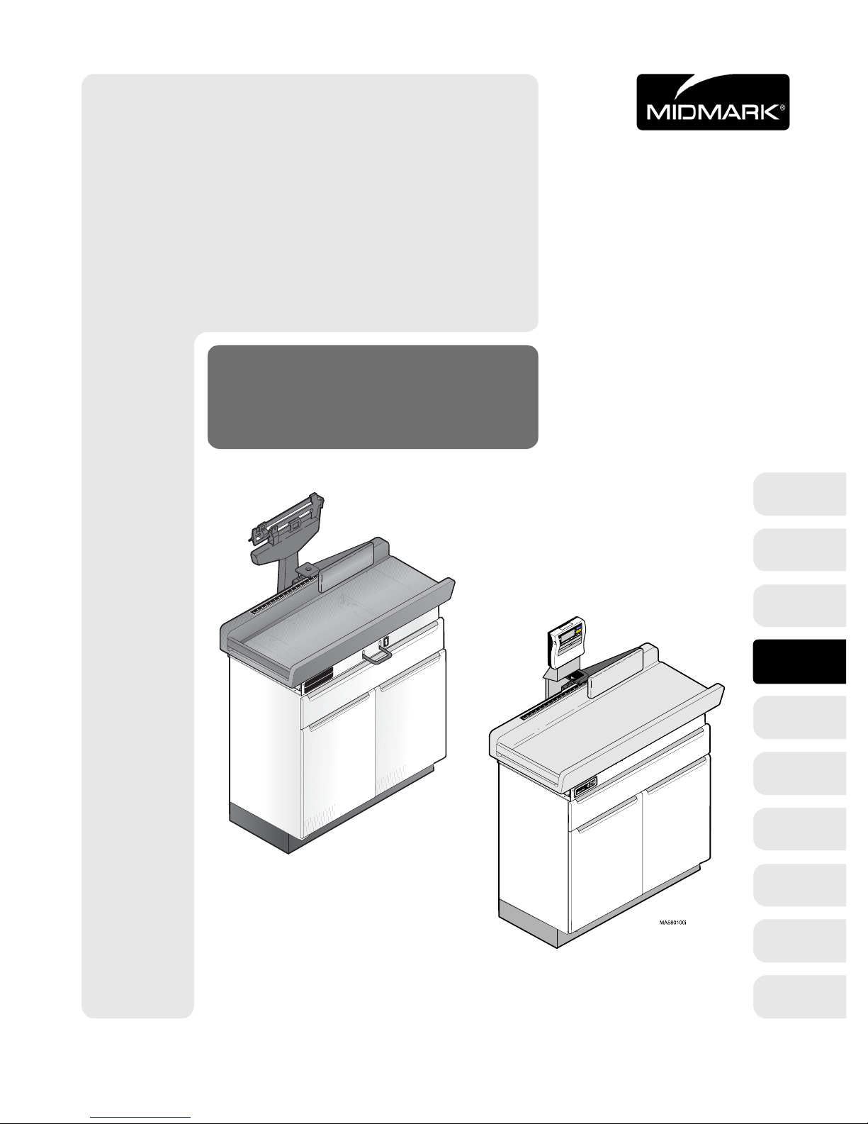
Pediatric Examination Table
Serial Number Prefixes:
RG, RH, RJ, RK, RL,
RM, & V
Parts Manual
409-004 & 409-005
FOR USE BY MIDMARK TRAINED TECHNICIANS ONLY
409-006 & 409-007
409
-00
thru
-00
SF-1561 Part No. 004-0070-00 Rev. K (4/04/08)
Page 2

Page 3

TABLE OF CONTENTS
TABLE OF CONTENTS
Section/Paragraph Page Section/Paragraph Page
IMPORTANT INSTRUCTIONS
General Safety Instructions ...........................................ii
Safety Alert Symbols .....................................................ii
Warranty Instructions .................................................. ii
SECTION I GENERAL INFORMATION
1.1 Scope of Manual .......................................... 1-1
1.2 How to Use Manual ...................................... 1-1
1.3 Description of 409 Pediatric Examination
Table.......................................................... 1-1
1.4 Specifications ............................................... 1-3
1.5 Standard Torque Specifications.................... 1-5
1.6 Parts Replacement Ordering........................ 1-5
1.7 Special Tools ................................................ 1-7
SECTION II TESTING AND TROUBLESHOOTING
2.1 Operational Test (Models 409-004 and
409-005).................................................... 2-1
2.2 Operational Test (Models 409-006 and
409-007).................................................... 2-3
2.3 Troubleshooting Procedures (Models
409-004 and 409-005)............................... 2-4
2.4 Troubleshooting Procedures (Models
409-006 and 409-007)............................... 2-6
SECTION III SCHEDULED MAINTENANCE
3.1 Scheduled Maintenance (Models
409-004 and 409-005).............................. 3-1
3.2 Scheduled Maintenance (Models
409-006 and 409-007).............................. 3-2
SECTION IV MAINTENANCE/SERVICE
INSTRUCTIONS
4.1 Introduction................................................... 4-1
4.2 Beam Scale Components Removal /
Installation (Mechanical Scale Only)....... 4-1
4.3 Zero Balance Adjustment (Mechanical
Scale Only)............................................... 4-2
4.4 Beam Scale Calibration Check
(Mechanical Scale Only)......................... 4-3
4.5 Platform Components Removal /
Installation or Table Top Locking
Mechanism Access (Mechanical
Scale Only)............................................... 4-4
4.6 Linear Scale Alignment (All Models)........... 4-6
4.7 Digital Display Removal / Installation
(Digital Scale Only) ................................. 4-6
4.8 Platform Scale Components / Load Cell
Assembly Access (Digital Scale
Only)......................................................... 4-7
4.9 Platform Load Cell Removal / Installation
(Digital Scale Only)................................. 4-9
4.10 Platform Assembly Removal / Installation
(Digital Scale Only)................................. 4-9
4.11 Display Board Assembly Removal /
Installation (Digital Sca le Only)............. 4-10
4.12 Digital Scale Calibration............................. 4-12
4.13 Digital Scale Gravitational Compensation
Adjustment.............................................. 4-13
4.14 Display Board Assembly Mode Setting
Procedure (Digital Scale Only) ............. 4-13
4.15 AUTO Power Off / Continuous Use
Selection Procedure (Digital Scale
Only)....................................................... 4-14
SECTION V SCHEMATICS AND DIAGRAMS
None.
SECTION VI PARTS LIST
6.1 Introduction ................................................ 6-1
6.2 Description of Columns................................ 6-1
6.3 Torque Specifications And Important
Assembly Notes........................................ 6-1
Pictorial Index [s/n prefix “JS”] ..................... 6-2
Pictorial Index [s/n prefix “PP”]..................... 6-3
Cabinet Assembly ....................................... 6-4
Upper Wrap [s/n prefix “JS”]:
w/ Mechanical Scale............................... 6-5.*
w/o Mechanical Scale............................. 6-6.*
Table Top Assembly [s/n prefix “JS”]:
w/ Mechanical Scale................................. 6-7
w/o Mechanical Scale............................... 6-8
Upper Wrap [s/n prefix “PP”] ....................... 6-9
Table Top Assembly [s/n prefix “PP”]:
w/ Digital Scale ....................................... 6-10
w/o Digital Scale..................................... 6-11
Tanita Scale Components ........................ 6-12.*
Weight Calibration...................................... 6-13
Key And Lock Assembly............................. 6-14
COMMENTS ............................................................. 7-1
FAX ORDER FORM.................................................. 7-2
(*) Indicates that there has been a serial number break for the illustration
and that there are additional point page(s) following the original page.
© Midmark Corporation 1998 SF-1561 Page i Printed in U.S.A.
Rev. 8/02
Page 4
TABLE OF CONTENTS
General Safety Instructions
Safety First: The primary concern of Midmark Corporation is that this table is maintained with the safety
of the patient and staff in mind. To assure that services
and repairs are completed safely and correctly, proceed
as follows:
(1) Read this entire manual before performing any
services or repairs on this table.
(2) Be sure you understand the instructions con-
tained in this manual before attempting to service or repair this table.
Safety Alert Symbols
Throughout this manual are safety alert symbols that
call attention to particular procedures. These items are
used as follows:
DANGER
A DANGER is used for an imminently
hazardous operating procedure, practice, or condition which, if not correctly followe d,
will result in loss of life or serious personal
injury.
NOTE
A NOTE is used to amplify an operating procedure,
practice or condition.
Warranty Instructions
Refer to the Midmark “Limited Warranty” printed in the
Installation and Operation Manual for warranty information. Failure to follow the guidelines listed below will
void the warranty and/or render the 409 Pediatric
Examination Table unsafe for operation.
• In the event of a malfunction, do not attempt to
operate the table until necessary repairs have been
made.
• Do not attempt to disassemble table, replace malfunctioning or damaged components, or perform
adjustments unless you are one of Midmark’s
authorized service technicians.
• Do not substitute parts of another manufacturer
when replacing inoperative or damaged components. Use only Midmark replacement parts.
WARNING
A WARNING is used for a potentially
hazardous operating procedure, practice, or condition which, if not correctly followe d,
could result in loss of life or serious personal
injury.
CAUTION
A CAUTION is used for a potentially haz-
ardous operating procedure, practice, or
condition which, if not correctly followed, could result
in minor or moderate injury. It may also be used to
alert against unsafe practices.
EQUIPMENT ALERT
An EQUIPMENT ALERT is used for an
imminently or potentially hazardous operating procedure, practice, or condition which, if not
correctly followed, will or could result in serious, moderate, or minor damage to unit.
© Midmark Corporation 1998 SF-1561 Page ii Printed in U.S.A.
Page 5

SECTION I
GENERAL INFORMATION
SECTION I
GENERAL INFORMATION
1.1 Scope of Manual
This manual contains detailed troubleshooting, scheduled maintenance, maintenance, and service instructions for the 409 Pediatric Exam Table. This manual is
intended to be used by Midmark’s authorized service
technicians.
1.2 How to Use Manual
A. Manual Use When Performing Scheduled Mainte-
nance.
(1) Perform inspections and services listed in
Scheduled Maintenance Chart (Refer to
para 3.1 or 3.2).
(2) If a component is discovered to be faulty or out
of adjustment, replace or adjust component in
accordance with maintenance / service instructions (Refer to para 4.1).
B. Manual Use When Table Is Malfunctioning And
Cause Is Unknown.
(1) Perform an operational test on Table (Refer to
para 2.1 or 2.2).
(2) Perform troubleshooting procedures listed in
Troubleshooting Guide (Refer to para 2.3 or
2.4).
(3) If a component is discovered to be faulty or out
of adjustment, replace or adjust component in
accordance with maintenance / service instructions (Refer to para 4.1).
1.3 Description of 409 Pediatric Exam
Table
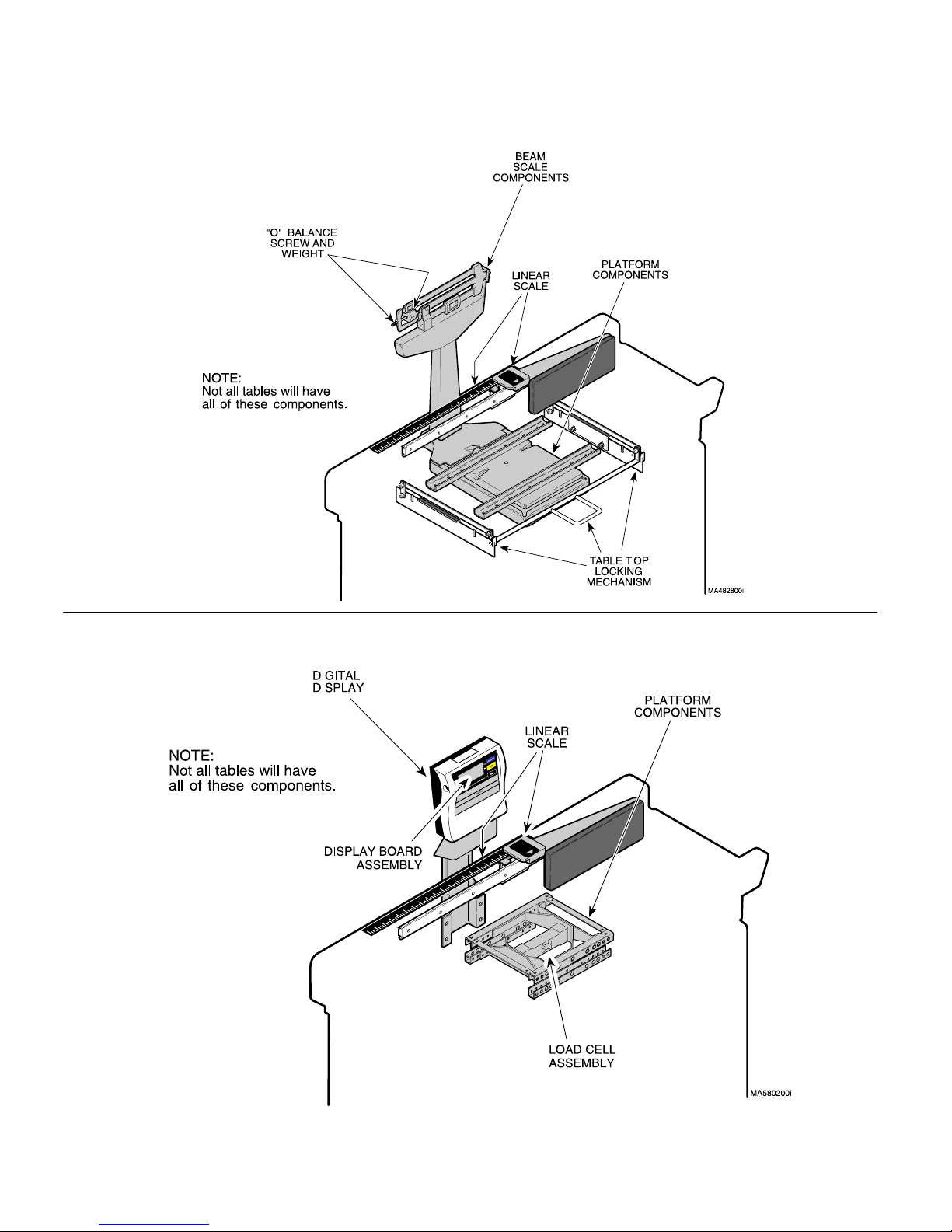
A. General Description (See Figure 1-1).
The 409 Pediatric Examination Table is a table designed
to be used by physicians and office staff to conduct routine medical examinations and measurements on pediatric patients weighing between 7.0 to 40.0 lbs (3.2 to
18.1 kg) and measuring 15.0 to 36.0 in. (38.1 to 91.4
cm) in length. Listed below are the four different models
available:
409-004............. Exam Table with mechanical scale
409-005............. Exam Table without mechanical scale
409-006............. Exam Table with digital scale
409-007............. Exam Table without digital scale
The major serviceable components of the 409-004 table
(table with mechanical scale) are the beam scale components which include the “0” balance screw & weight,
platform components, linear scale, and table top locking
mechanism. The major serviceable component of the
409-005 table (table without mechanical scale) is the
linear scale (See Figure 1-1).
The major serviceable components of the 409-006 table
(table with digital scale) are the digital display (which
includes display board assembly), platform components
(which includes load cell assembly), and linear scale.
The major serviceable component of the 409-007 table
(table without digital scale) is the linear scale (See Figure 1-1).
C. Manual Use When Damaged Component Is Known.
(1) Replace or adjust component in accordance
with maintenance / service instructions (Refer
to para 4.1).
© Midmark Corporation 1998 SF-1561 Page 1-1 Printed in U.S.A.
Rev. 3/01
Page 6
SECTION I
GENERAL INFORMATION
409-004 and 409-005
409-006 and 409-007
© Midmark Corporation 1998 SF-1561 Page 1-2 Printed in U.S.A.
Rev. 3/01
Figure 1-1. Major Components
Page 7

SECTION I
GENERAL INFORMATION
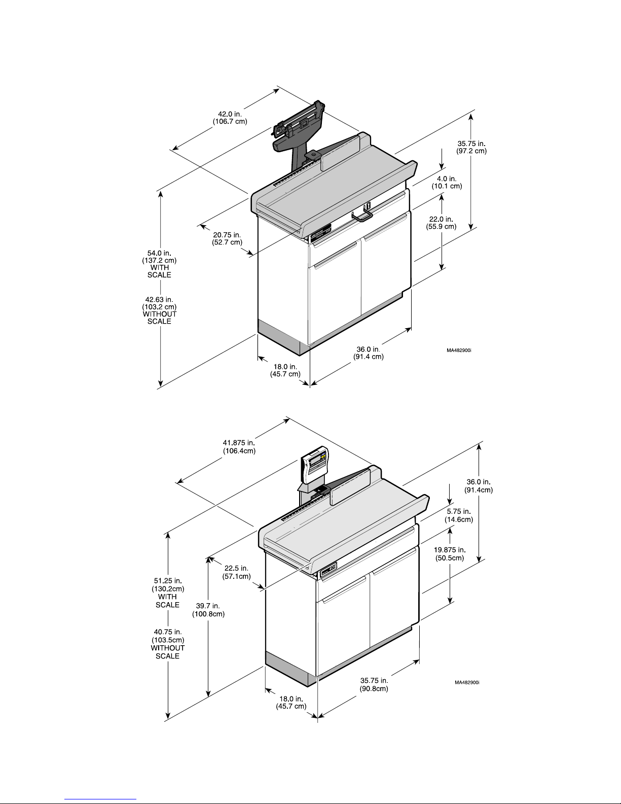
1.4 Specifications
Factual data for the 409 Pediatric Examination Table is
provided in Table 1-1. Also, see Figure 1-2.
Table 1-1. Specifications
Description Data
Patient Weight (409-004/409-005):
Maximum For Examination.................. 40 lbs (18.1 kg)
Maximum For Weighing ...................... 40 lbs (18.1 kg)
Patient Weight (409-006/409-007):
Maximum For Examination.................. 40 lbs (18.1 kg)
Maximum For Weighing ...................... 40 lbs (18.1 kg)
Weight of 409-004 Unit:
Boxed Weight ............................. 242.0 lbs (109.8 kgs)
Unboxed Weight ............................188.0 lbs (85.3 kgs)
Weight of 409-005 Unit:
Boxed Weight .............................. 215.0 lbs (97.5 kgs)
Unboxed Weight ............................161.0 lbs (73.0 kgs)
Weight of 409-006 Unit:
Boxed Weight ............................. 242.0 lbs (109.8 kgs)
Unboxed Weight ............................188.0 lbs (85.3 kgs)
Weight of 409-007 Unit:
Boxed Weight .............................. 215.0 lbs (97.5 kgs)
Unboxed Weight ............................161.0 lbs (73.0 kgs)
Overall Depth (w/o scale)...................... 21.5 (54.6 cm)
Overall Width ..............................41.875 in. (106.4 cm)
Beam Scale Accuracy (409-004):
up to 18.0 lbs (8.2 kg) is: ...................... ±1 oz. (28.3 g)
between 18-40 lbs (8.2 - 18.1 kg) is: ... ± 2 oz. (56.6.g)
over 40.0 lbs (18.1 kg) is:................... ± 4 oz. (113.3 g)
Beam Scale
Readout Increments (409-004):..................... minimum
increment is 1 oz. (20 g)
Digital Scale Accuracy (409-006):
0 - 11 lbs (0 - 5 kg) is: ........................... ±1.75 oz. (50 g)
11 - 40 lbs (5 - 18 kg) is: ....................... ±3.5 oz. (100 g)
[Serial #’s PP1143 thru present only register to 40 lbs]
40 - 100 lbs (18 - 45 kg) is: ................. ±5.25 oz. (150 g)
Digital Scale Readout
Minimum Increments (409-006):
Serial #’s: PP1000 thru PP1142 .............0.2 lb (0.09 kg)
Serial #’s: PP1143 thru present ..................1 oz (.01 kg)
Digital Scale Specifications:
Type Measurement ........ Electrical Resistance Method
Power Source ..................... Six LR6 Alkali Batteries or
AC Adapter - 9V, 300mA or more
center minus plug
Battery Life........................ 100 Hours Continuous Use
Power Consumption.................... 0.25 Watts maximum
Display ...................... LCD with 1 in. (25mm) numerals
Shipping Carton: ........... 45.0 in. "L" x 28.75 in. "W" x
43.0 in. "H"
Linear Scale
Accuracy:......................................... ± 1/8 in. (0.32 cm)
(114.3 cm x 73.0 cm x 109.2 cm)
Linear Scale Readout
Dimensions (409-004/409-005):
Minimum Increments: ...........................1/8 in. (0.5 cm)
Upholstered Top ..............20.75 in. wide x 42.0 in. long
(52.7 cm wide x 106.7 cm long)
Certifications:..................................ISO-9001 Certified
Table Top Work Height ................... 35.75 in. (97.2 cm)
Overall Height (w/scale) .................... 54 in. (137.2 cm)
Overall Height (w/o scale) .......... 40.625 in. (103.2 cm)
Overall Depth (w/scale) .................... 25.5 in. (64.8 cm)
Overall Depth (w/o scale) .................... 21.75 (55.2 cm)
Overall Width.................................. 42.0 in. (106.7 cm)
Dimensions (409-006/409-007):
Upholstered Top ..........20.75 in. wide x 41.875 in. long
(52.7 cm wide x 106.4 cm long)
Table Top Work Height ..................... 36.0 in. (91.4 cm)
Overall Height (w/scale) ............... 51.25 in. (130.2 cm)
Overall Height (w/o scale) ............ 40.75 in. (103.5 cm)
Overall Depth (w/scale) .................... 22.5 in. (57.1 cm)
© Midmark Corporation 1998 SF-1561 Page 1-3 Printed in U.S.A.
Rev. 6/07
Page 8
SECTION I
GENERAL INFORMATION
409-004 and 409-005
409-006 and 409-007
© Midmark Corporation 1998 SF-1561 Page 1-4 Printed in U.S.A.
Rev. 3/01
Figure 1-2. Dimensions
Page 9

SECTION I
GENERAL INFORMATION
1.5 Standard Torque Specifications
The following standard torque specifications in Table
1-2 apply to the various hardware used on the units
unless otherwise listed elsewhere in service procedures
or parts illustrations:
Table 1-2. Torque Specifications
Hardwa r e S ize Torque Values
#6 ............................11 to 21 inch / lbs. (1.2 to 2.3 N•M)
#8 ............................20 to 30 inch / lbs. (2.2 to 3.3 N•M)
#10 ..........................32 to 42 inch / lbs. (3.6 to 4.8 N•M)
1/4" .........................75 to 85 inch / lbs. (8.5 to 9.6 N•M)
5/16" .....................18 to 22 foot / lbs. (24.4 to 29.8 N•M)
3/8" .......................31 to 35 foot / lbs. (42.0 to 47.5 N•M)
1/2” .......................50 to 60 foot / lbs. (67.8 to 81.4 N•M)
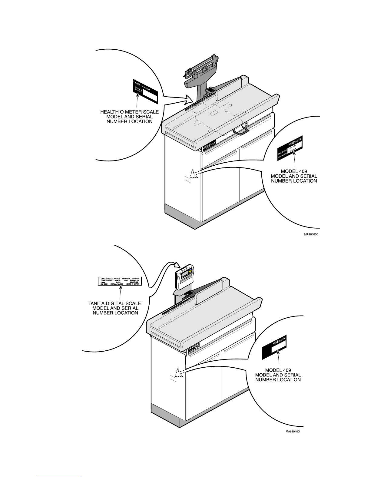
1.6 Parts Replacement Ordering
If a part replacement is required, order the part directly
from the factory as follows:
(1) Refer to Figure 1-3 to determine the location of
the model number and serial number of the
table and record this data.
(2) Refer to the Parts List to determine the item
numbers of the parts, part numbers of the
parts, descriptions of the parts, and quantities
of parts needed and record this data (Refer to
para 6.1).
NOTE
Ask the Purchasing Department of the company that
owns the unit for this information. Otherwise, this
information may be obtained from the dealer that sold
the unit.
(3) Determine the installation date of the table and
record this data.
(4) Call Midmark with the recorded information and
ask for the Medical Products Technical Services
Department. See back cover of this manual for
the phone number or use the Fax Order Form
(See page 7-2 for Fax Order Form).
© Midmark Corporation 1998 SF-1561 Page 1-5 Printed in U.S.A.
Rev. 3/01
Page 10
SECTION I
GENERAL INFORMATION
409-004 and 409-005
409-006 and 409-007
Figure 1-3. Model Number / Serial Number Location
© Midmark Corporation 1998 SF-1561 Page 1-6 Printed in U.S.A.
Rev. 3/01
Page 11

SECTION I
GENERAL INFORMATION
1.7 Special Tools
the table, how to obtain the special tools, and the purpose of each special tool.
Table 1-3 lists all of the special tools needed to repair
Table 1-3. Special Tool List
Description of Special Tool
Calibrated Test Weight
(included with & applies only to
409-004 table)
200kg or 440 lb Calibrated Test
Weight (applies to 409-006
table)
50 lb Calibrated Test Weight Commercially Available Any Type Used to check digital scale calibration.
Soldering iron & solder Commercially Available Any Type Used to desolder/solder two battery leads to dis-
Torque Wrench Commercially Available Any Type Used to tighten nuts or screws to specified values.
Manufacturer’s
Name / Address / Phone
Midmark Corporation
60 Vista Drive
Versailles, Ohio 45380
937-526-3662
Commercially Available Any Type Used to calibrate digital scale.
Manufacturer’s
Part N umbe r
050-4086-10 Used to calibration of the beam scale. A calibrated
test weight is included with each table from the factory. The test weight should be hanging on the
right rear of the table on a hook.
play board assembly when it is being replaced.
Purpose of Special Tool
© Midmark Corporation 1998 SF-1561 Page 1-7 Printed in U.S.A.
Rev. 3/01
Page 12

SECTION I
GENERAL INFORMATION
© Midmark Corporation 1998 SF-1561 Page 1-8 Printed in U.S.A.
Rev. 3/01
Page 13

TESTING AND TROUBLESHOOTING
SECTION II
TESTING AND TROUBLES HOOTING
SECTION II
2.1 Operational Test (Models 409-004
and 409-005) (See Figure 2-1)
In order to effectively diagnose a malfunction of the 409004 and 409-005 Pediatric Examination Table, it may be
necessary to perform an operational test as follows:
WARNING
Refer to the Operator Manual for com-
plete instructions on operating the
table. Failure to do so could result in personal
injury.
NOTE
The Operational Test, for the most part, only
describes what should happen when the table is
operated. If the table does something other than
described, a problem has been discovered. Refer to
the Troubleshooting Guide to determine the cause of
the problem and its correction.
Also, this operational test procedure is based on units
that have a beam scale; some units do not have a
beam scale - For these units skip to step 14.
(6) Remove any items from table top. Set large
poise weight to zero, making sure it is seated in
notch and set small poise weight to zero, making sure small poise weight is pushed firmly
against shoulder of beam.
(7) Observe. The beam pointer should balance in
center of trig square, indicating scale is zeroed.
NOTE
Use the calibrated test weight which should be hanging on a storage hook on the right rear of the table.
The test weight will have a label indicating the calibrated weight of the test weight.
(8) Place the calibrated test weight on center of
upholstered table top.
(9) Using the large poise weight and small poise
weight, set beam scale to a setting which is
equal to calibrated test weight.
(10) Observe. The beam pointer should center in
the trig square indicating beam scale is within
tolerance.
(1) Move table top locking handle to LOCK posi-
tion. Attempt to move table top (See
Figure 2-1).
(2) Observe. The table top should be firmly locked
into a stationary position.
(3) Move table top locking handle to UNLOCK posi-
tion.
(4) Observe. The table top should not be locked
into a stationary position anymore. Look
between table top and base. There should be
approximately a 1/4 in. (6.35 mm) gap between
locking rails and bottom of table top; at the very
least, there should not be any contact.
(5) Push down on center of table top a few times to
align and exercise all internal scale parts.
(11) If beam scale does not center, adjust the small
poise weight and/ or large poise weight as necessary to center beam pointer in trig square.
(12) Determine how much beam scale reading dif-
fers from weight of calibrated test weight. The
allowable tolerance is ±1 oz. (28.3 g).
(13) Hang the calibrated test weight on its storage
hook, located on right rear of table.
(14) Remove any items from table top and then
move table top locking handle to LOCK position.
(15) Extend linear scale fully. Using a carpenter
square, check to see if the linear scale is
square with back of table top when scale is fully
extended.
© Midmark Corporation 1998 SF-1561 Page 2-1 Printed in U.S.A.
Rev. 3/01
Page 14

SECTION II
TESTING AND TROUBLESHOOTING
LARGE POISE
WEIGHT
SMALL POISE
WEIGHT
LOCKING RAILS
(LEFT SIDE SHOWN)
TRIG
SQUARE
BEAM
POINTER
LINEAR
SCALE
CARPENTERS
SQUARE
TABLE
TOP
409
MIDMARK
Pediatric
Figure 2-1. Operational Test (Models 409-004 & 409-005)
TABLE TOP
LOCK/UNLOCK
HANDLE
MA483100
© Midmark Corporation 1998 SF-1561 Page 2-2 Printed in U.S.A.
Rev. 3/01
Page 15
SECTION II
TESTING AND TROUBLESHOOTING
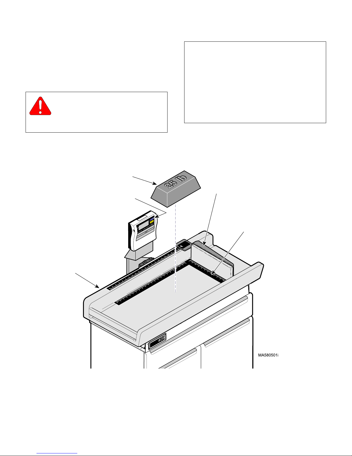
2.2 Operational Test (Models 409-006
and 409-007) (See Figure 2-2)
In order to effectively diagnose a malfunction of the 409006 and 409-007 Pediatric Examination Table, it may be
necessary to perform an operational test as follows:
WARNING
Refer to the Operator Manual for com-
plete instructions on operating the
table. Failure to do so could result in personal
injury.
25 lb (11.3 kg)
TEST WEIGHT
ON / ZERO
BUTTON
NOTE
The Operational Test, for the most part, only
describes what should happen when the table is
operated. If the table does something other than
described, a problem has been discovered. Refer to
the Troubleshooting Guide to determine the cause of
the problem and its correction.
Also, this operational test procedure is based on units
that have a digital scale; some units do not have a
digital scale - For these units skip to step 7.
LINEAR
SCALE
TABLE
TOP
MIDMARK
Figure 2-2. Operational Test (Models 409-006 & 409-007)
(1) Press ON / ZERO button to turn digital scale
ON.
CARPENTERS
SQUARE
© Midmark Corporation 1998 SF-1561 Page 2-3 Printed in U.S.A.
Rev. 6/07
Page 16
SECTION II
TESTING AND TROUBLESHOOTING
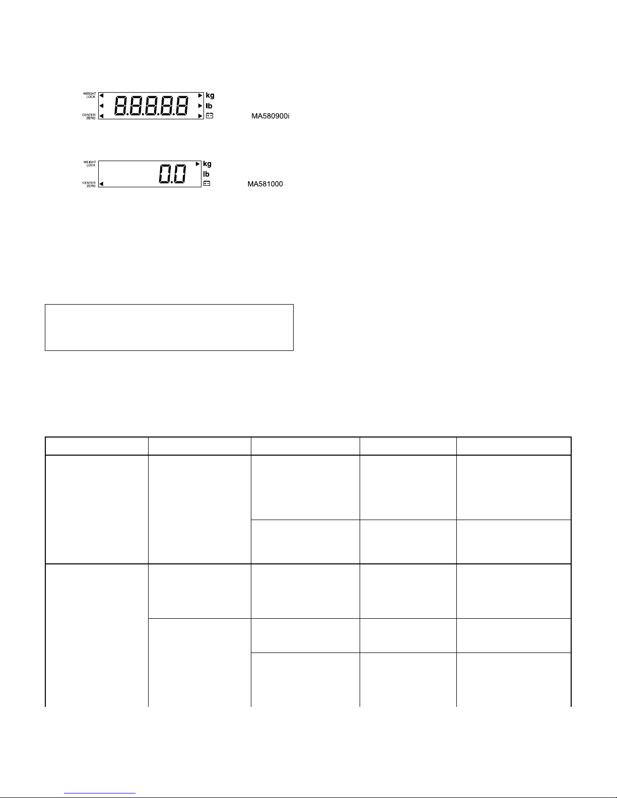
(2) Observe. The display should flash
momentarily and then the display should display
Make sure all LCD segments illuminate properly.
(3) Check all functions of digital display (Reference
TANITA BWB-800 operating Instructions Manual).
(4) Press KG / LB button until display is set to LB.
NOTE
Use the calibrated test weight to perform the following procedure.
(6) Determine how much digital scale reading dif-
fers from weight of calibrated test weight. The
allowable tolerance is ±5.25 oz. (150 g).
(7) Remove calibrated test weight and then press
ON / ZERO to turn digital scale OFF.
(8) Extend linear scale fully. Using a carpenter
square, check to see if the linear scale is
square with back of table top when scale is fully
extended.
2.3 Troubleshooting Procedures
(Applies to 409-004 and 409-005)
Table 2-1 is a Troubleshooting Guide which is used to
determine the cause of the malfunction. This guide covers problems with scale platform components, beam
scale components, and linear scale components which
the model 409-004 has. The model 409-005 does not
have a scale platform or beam scale; it only has a linear
scale. For this model, only use the portion of the guide
which is applicable.
(5) Place a calibrated 25 lb (11.3 kg) test weight on
center of table top.
Table 2-1. Troubleshooting Guide (Models 409-004 & 409-005)
Problem Symptom Probable Cause Check Correction
Table top will not lock into
stationary position properly.
Weight scale does not
measure weight accurately.
When table top locking
handle is moved to the
LOCK position, the table
top is not locked into stationary position (can still be
moved).
The beam pointer will not
center when the large and
small poise weights are set
to zero.
The measured weight of
the patient is inaccurate.
Table top locking mechanism
has bent, broken, or missing
components.
Platform has worn “V” bearings or a broken pivot.
The beam scale is not
zeroed.
Paper roll is interfering with
table top.
Locking rails are not releasing properly when table top
locking handle is moved to
the UNLOCK position.
Check for bent, broken,
or missing components.
Check for worn “V” bearings or a broken pivot.
Check to see if the beam
pointer centers when the
large and small poise
weights are set to zero.
Check to see if paper roll
is in contact with bottom
of table top.
Check for bent or missing
components in table top
locking mechanism. See
why locking rails are
“hanging up”.
Replace any bent, broken, or
missing components on the
table top locking mechanism.
Refer to para 4.5 to gain
access.
Replace platform assembly
and beam scale assembly (are
a factory matched unit). Refer
to para 4.2 and 4.5.
If beam pointer does not center when the large and small
poise weights are set to zero,
perform a zero balance adjustment. Refer to para 4.3.
Reduce thickness of paper roll
or remove paper roll.
Repair or replace any bent,
broken, or missing components on the table top locking
mechanism. Refer to para 4.5
to gain access.
© Midmark Corporation 1998 SF-1561 Page 2-4 Printed in U.S.A.
Rev. 6/07
Page 17

Table 2-1. Troubleshooting Guide (Models 409-004 & 409-005) - Continued
Problem Symptom Probable Cause Check Correctio n
Linear scale seems to be
inaccurate.
Beam pointer does not
move at all during weighing.
Arm of linear scale is not
perpendicular to upholstered top when extended
or height measurements
seem inaccurate.
TESTING AND TROUBLESHOOTING
Table is not level. Check to see if table top
Beam pointer is touching the
the side of the trig square
during its travel.
Patient is not being centered on the table top before
being weighed.
Platform is rocking excessively or touches its base at
any corner as a result of a
worn or broken “V” bearing
or a broken pivot.
Steel connecting rod which
connects beam scale and
weight platform is rubbing
against inside of scale pillar.
Beam scale is out of calibration.
Connection rod is incorrectly connected or has
become disconnected from
linkage rods.
Scale label is not positioned
properly.
Linear scale is out of alignment (not square with back
of table top).
is level.
Press down on the center
of the table top while
observing the beam
pointer.
Check to see if table
operator is positioning
patient properly.
Check for worn or broken
“V” bearings or a broken
pivot.
Check to see if all wire
hooks of steel connecting
rod face toward the right
side of the table.
Check accuracy of scale
with the calibrated test
weight.
Check connection rod
connections.
Use tape measure to
check if scale label is
positioned properly.
Use a carpenter square
to check squareness of
linear scale with respect
to the back of table top.
SECTION II
Adjust four leveling screws,
located on base of table, to
level table.
Replace platform assembly
and beam scale assembly (are
a factory matched unit). Refer
to para 4.2 and 4.5.
Inform operator of correct
patient positioning for weighing.
Replace platform assembly
and beam scale assembly (are
a factory matched unit). Refer
to para 4.2 and 4.5.
Position all wire hooks so they
face the right side of table.
Refer to para 4.2.
Check the calibration of the
beam scale using the calibrated test weight. Refer to
para 4.4. If scale is out of calibration, replace platform
assembly and beam scale
assembly (are a factory
matched unit). Refer to para
4.2 and 4.5.
Connect disconnected connection rod. Make sure all
other linkage is correctly positioned and connected to connection rod.
Reposition scale label or if
necessary, replace with new
scale label.
Align linear scale. Refer to
para 4.6.
© Midmark Corporation 1998 SF-1561 Page 2-5 Printed in U.S.A.
Rev. 3/01
Page 18

SECTION II
TESTING AND TROUBLESHOOTING
2.4 Troubleshooting Procedures
(Applies to 409-006 and 409-007)
Table 2-2 is a Troubleshooting Guide which is used to
determine the cause of the malfunction. This guide covers problems with scale platform components and digital display which the model 409-006 has. The model
Table 2-2. Troubleshooting Guide (Models 409-006 & 409-007)
Problem Symptom Probable Cause Check Correctio n
Digital Scale is malfunctioning.
Nothing is displayed on
digital display when ON /
ZERO switch is pressed.
Digital display acts erratically.
Digital display works, but
measured weight stays at
zero even with weight on
table top.
The measured weight of
the patient is inaccurate.
AC adapter is malfunctioning
or disconnected (applies
only if AC adapter is being
used instead of batteries).
Batteries are too weak to
operate digital scale (applies
only if batteries are being
used instead of AC adapter).
Display board assembly is
malfunctioning.
The mode setting for the digital display has been lost due
to a power surge or replacement of display board
assembly.
Display connector (connects
to underside of digital display) is loose or disconnected from digital display.
Wiring / connector between
display board assembly and
platform scale load cell is
disconnected or torn.
Platform scale load cell
assembly is malfunctioning.
Paper roll is interfering with
table top.
Table is not level. Check to see if table top
Table is located where
excessive vibration occurs.
409-007 does not have a scale platform or digital display; it only has a linear scale. For this model, only use
the portion of the guide which is applicable.
Check the connection of
the AC adapter jack to
the AC jack port and the
connection of AC adaptor
plug to the wall outlet.
Replace suspect batteries with known working
batteries or use an AC
adapter.
Replace suspect display
board assembly with
known working display
board assembly.
Check mode setting for
unit.
Check if display connector is loose or disconnected.
Check for disconnected,
torn, or damaged connector / wiring.
Replace suspect platform
scale load cell with
known working platform
scale load cell.
Check to see if paper roll
is in contact with bottom
of table top.
is level.
Check for signs of excessive vibration at table
location.
Correct bad connection. If
necessary, replace AC
adapter (Call TANITA Corporation @847-640-9241 to order
parts /accessories).
Replace six used batteries
with six new LR6 Alkali batteries (“AA” Batteries).
Replace display board assembly (Call TANITA Cor poration
@847-640-9241 to order parts
/accessories).
Adjust mode setting for digital
scale to code:H8830. This is
the type of scale used on this
table. Refer to para 4.14.
Make sure display connector
is properly connected to digital
display.
Connect loose connector or
replace any torn or damaged
connector / wiring. (Call TANITA Corporation @847-6409241 to order parts /accessories.) Refer to para 4.8.
Replace platform scale load
cell. Refer to para 4.9. (Call
TANITA Corporation @847640-9241 to order parts /
accessories.)
Reduce thickness of paper roll
or remove paper roll.
Adjust four leveling screws,
located on base of table, to
level table.
Accurate measurement may
be impossible if the product is
used where there is excessive
vibration. Try using the table
at another location.
© Midmark Corporation 1998 SF-1561 Page 2-6 Printed in U.S.A.
Rev. 3/01
Page 19

Table 2-2. Troubleshooting Guide (Models 409-006 & 409-007) - Continued
Problem Symptom Probable Cause Check Correctio n
Linear scale seems to be
inaccurate.
Arm of linear scale is not
perpendicular to upholstered top when extended
or height measurements
seem inaccurate.
TESTING AND TROUBLESHOOTING
Digital scale is out of calibration.
Display board assembly is
malfunctioning.
Wiring / connector between
display board assembly and
platform scale regulator is
disconnected or torn.
Platform scale load cell
assembly is malfunctioning.
Scale label is not positioned
properly.
Linear scale is out of alignment (not square with back
of table top).
Check accuracy of digital
scale with a calibrated 50
lb (22.7 kg) test weight.
The allowable tolerance
± 5.25 oz. (150 g).
is
Replace suspect display
board assembly with
known working display
board assembly.
Check for disconnected,
torn, or damaged connector / wiring.
Replace suspect platform
scale load cell with
known working platform
scale load cell.
Use tape measure to
check if scale label is
positioned properly.
Use a carpenter square
to check squareness of
linear scale with respect
to the back of table top.
SECTION II
Check the calibration of the
digital scale using the calibrated test weight. If digital
scale is out of calibration, calibrate digital scale. Refer to
para 4.12.
Replace display board assembly. Refer to para 4.11. (Call
TANITA Corporation @847640-9241 to order parts /
accessories.)
Connect loose connector or
replace any torn or damaged
connector / wiring. (Call TANITA Corporation @847-6409241 to order parts /accessories.) Refer to para 4.8.
Replace platform scale load
cell. Refer to para 4.9. (Call
TANITA Corporation @847640-9241 to order parts /
accessories.)
Reposition scale label or if
necessary, replace with new
scale label.
Align linear scale. Refer to
para 4.6.
© Midmark Corporation 1998 SF-1561 Page 2-7 Printed in U.S.A.
Rev. 3/01
Page 20

SECTION II
TESTING AND TROUBLESHOOTING
© Midmark Corporation 1998 SF-1561 Page 2-8 Printed in U.S.A.
Rev. 3/01
Page 21

SCHEDULED MAINTENANCE
SECTION III
SCHEDULED MAINTENANCE
SECTION III
3.1 Scheduled Maintenance (Models
409-004 and 409-005)
This guide covers inspections on tables with platform
components, beam scale components, and linear scale
components which the model 409-004 has. The model
Table 3-1 is a Scheduled Maintenance Chart which lists
the inspections and services that should be performed
periodically on the 409-004 & 409-005) Pediatric Exam-
409-005 does not have a platform or beam scale; it has
only a linear scale. For this model, only use the portion
of the guide which is applicable.
ination Table. These inspections and services should
be performed as often as indicated in the chart.
Table 3-1. Scheduled Maintenance
Interval Inspection or Service What to Do
Semi-annually Obvious damage Visually check condition of table for obvious damage such as: cracks in components, missing com-
Fasteners / hardware Check table for missing or loose fasteners / hardware. Replace any missing hardware and tighten
Warning and instructional
decals
Pivot points / moving
parts / accessories
Table top locking mechanism
Beam scale zero balance Zero the large and small poise weights; the beam pointer should center in the trig square indicating
Beam scale accuracy Check to see if beam scale reading matches the calibrated test weight placed on table top (within
Linear scale Use carpenter square to ensure linear scale is square with back of table top when fully extended. If
Levelness of table Check to see if table is level. If not, level table by adjusting leveling screws; there is one located at
Upholstery Check upholstered table top for rips, tears, or excessive wear. Replace table top if necessary.
Operational Test Perform an Operational Test to determine if the table is operating within its specifications. Refer to
ponents, dents in components, or any other visible damage which would cause the table to be
unsafe to operate or would compromise its performance. Repair table as necessary.
any loose hardware as necessary.
Check for missing or illegible decals. Replace decals as necessary.
Lubricate all exposed pivot points, moving parts, and accessories with silicone based lubricant.
Refer to para 4.5 for access.
Check that table top is stationary when table top locking handle is in the LOCK position. Check that
table top floats freely on scale platform when table top locking mechanism is in UNLOCK position.
If not, replace any bent, broken, or missing components on table top locking mechanism. If necessary, replace platform assembly and beam scale assembly (are a factory matched unit). Refer to
para 4.2 and 4.5.
scale is zeroed. If not, perform a zero balance adjustment. Refer to para 4.3.
specified tolerance). Refer to para 4.4. If not, replace platform assembly and beam scale assembly (are a factory matched unit). Refer to para 4.2 and 4.5.
not, align linear scale. Refer to para 4.6. Use tape measure to make sure linear scale label is positioned correctly, indicating the correct patient measurement.
each corner of table.
para 2.1. Replace or adjust any malfunctioning components.
© Midmark Corporation 1998 SF-1561 Page 3-1 Printed in U.S.A.
Rev. 3/01
Page 22

SECTION III
SCHEDULED MAINTENANCE
3.2 Scheduled Maintenance (Models
409-006 and 409-007)
This guide covers inspections on tables with platform
components, digital display, and linear scale components which the model 409-006 has. The model 409-
Table 3-2 is a Scheduled Maintenance Chart which lists
the inspections and services that should be performed
periodically on the 409-006 & 409-007) Pediatric Exam-
007 does not have a platform or digital display; it has
only a linear scale. For this model, only use the portion
of the guide which is applicable.
ination Table. These inspections and services should
be performed as often as indicated in the chart.
Table 3-2. Scheduled Maintenance
Interval Inspection or Service What to Do
Semi-annually Obvious damage Visually check condition of table for obvious damage such as: cracks in components, missing com-
ponents, dents in components, or any other visible damage which would cause the table to be
unsafe to operate or would compromise its performance. Repair table as necessary.
Fasteners / hardware Check table for missing or loose fasteners / hardware. Replace any missing hardware and tighten
Warning and instructional
decals
Pivot points / moving
parts / accessories
Digital Display
Linear scale Use carpenter square to ensure linear scale is square with back of table top when fully extended. If
Levelness of table Check to see if table is level. If not, level table by adjusting leveling screws; there is one located at
Upholstery Check upholstered table top for rips, tears, or excessive wear. Replace table top if necessary.
Operational Test Perform an Operational Test to determine if the table is operating within its specifications. Refer to
Annually Digital scale calibration Perform a digital scale calibration and then a gravity compensation procedure. Refer to para 4.12
any loose hardware as necessary.
Check for missing or illegible decals. Replace decals as necessary.
Lubricate all exposed pivot points, moving parts, and accessories with silicone based lubricant.
Check accuracy of scale using a 50 lb (22.7 kg) test weight. The allowable tolerance is
(150 g). If necessary, calibrate digital scale (Refer to para 4.12). Check all LCD segments to
ensure they are illuminating. If necessary, replace display board (Refer to para 4.11).
not, align linear scale. Refer to para 4.6. Use tape measure to make sure linear scale label is positioned correctly, indicating the correct patient measurement.
each corner of table.
para 2.2. Replace or adjust any malfunctioning components.
and 4.13.
± 5.25 oz.
© Midmark Corporation 1998 SF-1561 Page 3-2 Printed in U.S.A.
Rev. 3/01
Page 23

MAINTENANCE / SERVICE
SECTION IV
MAINTENANCE / SERVICE INSTRUCTIONS
SECTION IV
4.1 Introduction
WARNING
Refer to the Operator Manual for com-
plete instructions on operating the
table. Failure to do so could result in personal
injury.
NOTE
Perform an operational test on the table after the
repair is completed to confirm the repair was properly
made and that all malfunctions were repaired.
Also, this guide covers procedures on platform components, beam scale components, and linear scale
components which the model 409-004 has. The
model 409-005 does not have a platform or beam
scale; it only has a linear scale. For this model, only
use the procedures which are applicable.
The following paragraphs contain removal, installation,
repair, and adjustment procedures for the table.
4.2 Beam Scale Components Removal /
Installation (Mechanical Scale Only)
(5) Disconnect lever assembly (7) from wire loop
(D) and remove lever assembly.
(6) Remove four locknuts (8) and pillar assembly
(4) from base assembly (9).
B. Installation
(1) Install pillar assembly (4) on base assembly (9)
and secure with four locknuts (8).
EQUIPMENT ALERT
The open ends of all wire loops must face
the operator’s right side of the table after
being installed. Failure to do so will result in inaccurate readings.
(2) Position lever assembly (7) inside pillar assem-
bly (4); then connect lever assembly to wire
loop (D).
(3) Connect wire loop (B) of connection rod (6) to
lever assembly (7); then connect wire loop (C)
of connection rod (6) to calibrating arm (10).
(4) Install beam scale (5) on pillar assembly (4).
A. Removal
EQUIPMENT ALERT
The serial number labels on both the pillar
assembly (4, Figure 4-1) and platform
base (12, Figure 4-5) must match each other; they
are a factory matched pair. If serial numbers do not
match, do not proceed with beam scale installation,
stop and call Midmark Technical Service at 1-800MIDMARK.
(1) Remove two screws (1, Figure 4-1), front cap
(2), and back cap (3) from pillar assembly (4).
(2) Disconnect wire loop (A) from beam scale (5).
(3) Remove beam scale (5) from pillar
assembly (4).
(4) Disconnect wire loops (B and C) and remove
connection rod (6).
NOTE
Pull upward gently on wire loop (A) to create slack so
wire loop can be connected to beam scale.
(5) Connect wire loop (A) of lever assembly (7) to
beam scale (5).
(6) Install back cap (3) and front cap (2) over beam
scale (5) and secure with two screws (1).
(7) Perform zero balance adjustment (Refer to
para 4.3).
(8) Check beam scale calibration (Refer to
para 4.4).
© Midmark Corporation 1998 SF-1561 Page 4-1 Printed in U.S.A.
Rev. 3/01
Page 24

SECTION IV
A
800600
400
200
800
5
4
600400
200
250 300
200
4
3
7
6
5
2
1
MAINTENANCE / SERVICE
1
5
A
D
2
3
1
D
4
A
MA483300
Figure 4-2. Zero Balance Adjustment
B
6
C
10
7
C
8
Figure 4-1. Beam Scale Components
Removal / Installation
4.3 Zero Balance Adjustment (Mechanical Scale Only)
A. Adjustment
(1) Move the table top locking handle (1, Figure 4-
2) to UNLOCK position.
(2) Push down on center of table top (Point A) a
few times to align and exercise all internal parts.
9
(4) Set large poise weight (3) to zero setting, mak-
ing sure it is seated in notch and set small poise
weight (4) to zero setting by making sure small
poise weight is pushed firmly against shoulder
of beam (all the way to left).
(5) Observe. The beam pointer (5) should center
MA483200
in trig square (6), indicating the beam scale is
zeroed.
(6) If the beam pointer (5) centers, no adjustment is
necessary. If the beam pointer does not center,
go to step 7.
NOTE
If beam pointer touches bottom of trig square or stabilizes below the centerline of trig square, turn zero
adjustment screw in a clockwise direction. If beam
pointer touches top of trig square or stabilizes above
the centerline of trig square, turn zero adjustment
screw in a counterclockwise direction.
(3) Remove any items from upholstered table
top (2).
© Midmark Corporation 1998 SF-1561 Page 4-2 Printed in U.S.A.
Rev. 3/01
(7) Turn zero adjustment screw (7) in or out until
beam pointer (5) centers in trig square (6).
Page 25

4.4 Beam Scale Calibration Check
(Mechanical Scale Only)
A. Calibration Check
SECTION IV
MAINTENANCE / SERVICE
3
CAUTION
This procedure only checks to make sure
the beam scale is still calibrated within tolerance. The beam scale cannot be calibrated in the
field. If the beam scale does not pass the calibration
check (after performing a zero balance adjustment),
the scale platform and beam scale components must
be replaced; the scale platform and beam scale components are factory calibrated and are shipped as a
matched pair.
(1) Move table top locking handle (1, Figure 4-3) to
UNLOCK position.
(2) Remove any items from upholstered table
top (2).
(3) Push down on center of upholstered table top
(A) a few times to align and exercise all internal
parts.
(4) Perform zero balance adjustment (Refer to
para 4.3).
EQUIPMENT ALERT
Use calibrated test weight provided; a label
indicating the calibrated weight is on test
weight. Failure to use calibrated test weight could
result in a faulty calibration check reading.
(5) Remove calibrated test weight (3) from its stor-
age hook, located on right rear of table. Place
calibrated test weight on center of upholstered
table top (A).
7
4
5
6
2
MIDMARK
Pediatric
Figure 4-3. Scale Calibration
(8) If beam pointer (6) centers, beam scale is prop-
erly calibrated. If beam pointer does not center,
adjust small poise weight (5) and / or large
poise weight (4) as necessary to center beam
pointer (6) in trig square (7).
409
A
1
MA483400
(6) Using large poise weight (4) and small poise
weight (5), set beam scale to weight indicated
on calibrated test weight.
(7) Observe. The beam pointer (6) should center
in trig square (7), indicating beam scale is
within tolerance.
© Midmark Corporation 1998 SF-1561 Page 4-3 Printed in U.S.A.
Rev. 3/01
CAUTION
The beam scale cannot be calibrated in
the field. If the beam scale does not pass
the calibration check (after performing a zero balance
adjustment), the scale platform and beam scale components must be replaced; the scale platform and
beam scale components are factory calibrated and
are shipped as a matched pair.
Page 26

SECTION IV
MIDMARK
Pediatric
409
MAINTENANCE / SERVICE
NOTE
The allowable difference listed below is based on a
test weight of 18 lbs (8.2 kgs) or less.
(9) Determine how much beam scale reading dif-
fers from weight of calibrated test weight. The
allowable difference is ±1 oz. (±28.3 g); if the
difference is more than ±1 oz. (±28.3 g), the
scale platform and beam scale components
must be replaced (Refer to para 4.2 and 4.5).
(10) Hang calibrated test weight (3) on its storage
hook, located on right rear of table.
4.5 Platform Components Removal /
Installation or Table Top Locking
Mechanism Access (Mechanical
Scale Only)
A. Removal
EQUIPMENT ALERT
The serial number labels on both the pillar
assembly (4, Figure 4-1) and platform
base (12, Figure 4-5) must match each other; they
are a factory matched pair. If serial numbers do not
match, do not proceed with beam scale installation,
stop and call Midmark Technical Service at 1-800MIDMARK.
(1) Pull drawer (1, Figure 4-4) out until resistance is
felt. Then, on both sides of drawer, pull sides of
drawers outward until locking slots (A) of drawer
are free of tabs (B) on door glides (2). Remove
drawer (1) from table.
(2) Remove four screws (1, Figure 4-5), lockwash-
ers (2), washers (3), and upholstered table top
(4) from base (5).
(3) Lift up slightly on calibrating arm (6) and then
disconnect wire hook (7) from calibrating arm.
(4) Remove four nuts (8) and beam scale assembly
(9) from platform (10).
(5) Remove four screws (11), lockwashers (12),
and platform (10) from upholstered table
top (4).
409
MIDMARK
Pediatric
1
3
A
B
MA483500
Figure 4-4. Drawer Removal / Installation
B. Installation
(1) Install platform (10, Figure 4-5) on upholstered
table top (4) and secure with four lockwashers
(12) and screws (11).
NOTE
If installing a new beam scale, skip steps 2 and 3.
Then, after step 5, install the new beam scale components (Refer to para 4.2).
(2) Install beam scale assembly (9) on platform
(10) and secure with four nuts (8),
(3) Lift up slightly on calibrating arm (6) and then
connect wire hook (7) to calibrating arm.
(4) Install upholstered table top (4) on base (5) and
secure with four washers (3), lockwashers (2),
and screws (1).
(5) Install drawer (1, Figure 4-4) by positioning
drawer on drawer glides (2), making sure rear
of drawer is contained by two hooks (3); then
2
Rev. 3/01
© Midmark Corporation 1998 SF-1561 Page 4-4 Printed in U.S.A.
Page 27

SECTION IV
6
7
MAINTENANCE / SERVICE
pull sides of drawers outward and install locking slots (A) of drawers on tabs (B).
9
10
4
8
12
11
MIDMARK
Pediatric
409
UNLOCK
LOCK
5
3
2
1
Figure 4-5. Platform Components Removal / Installation
© Midmark Corporation 1998 SF-1561 Page 4-5 Printed in U.S.A.
Rev. 3/01
MA483600
Page 28

SECTION IV
MAINTENANCE / SERVICE
4.6 Linear Scale A li gnment (All Models)
A. Alignment
(1) Open measuring arm of linear scale (1, Figure
4-6) to its fully extended position as shown in
illustration.
(2) Using a carpenter square (A), check to see if
the measuring arm of linear scale (1) is square
with back of upholstered table top (2) when linear scale is fully extended.
(3) If measuring arm of linear scale (1) is not
square, use a 3/32 in. Allen wrench to adjust
setscrew (3) until linear scale is square with
back of upholstered table top (2).
4.7 Digital Display Removal / Installation (Digital Scale Only)
A. Removal
(1) Disconnect display connector (1, Figure 4-7)
from digital display (2).
Figure 4-6. Linear Scale Alignment
Figure 4-7. Digital Display Removal / Installation
(2) If using AC adapter, disconnect AC adapter jack
(3) from digital display (2).
(3) Remove two screws (4), spacers (5), and digital
display (2) from scale readout holder (6).
B. Installation
(1) Install digital display (2) on scale readout holder
(6) and secure with two spacers (5) and
screws (4).
EQUIPMENT ALERT
Use locator arrow to ensure display con-
nector is installed in correct orientation.
Also, do not use excessive force to connect. Failure
to do so could result in damage to display connector
or digital display.
(2) Connect display connector (1) to digital
display (2), making sure locator arrow (A) is facing front side of digital display.
© Midmark Corporation 1998 SF-1561 Page 4-6 Printed in U.S.A.
Rev. 3/01
Page 29

SECTION IV
MAINTENANCE / SERVICE
(3) Perform digital scale calibration (Refer to
para 4.12).
(4) Perform digital scale gravitational compensa-
tion adjustment (Refer to para 4.13).
4.8 Platform Scale Components / Load
Cell Assembly Access (Digital Scale
Only)
A. Removal
(1) Disconnect display connector (1, Figure 4-8)
from digital display (2); then remove cord of display connector from cable clamp (3).
(2) If using AC adapter, disconnect AC adapter jack
(4) from digital display (2).
(3) Remove drawer (5) from table as follows: pull
drawer out until it meets resistance. Then, on
both sides of drawer (5), bend sides of drawer
outward until locking slots (6) of drawer are free
of tabs (7) on drawer slides.
(3) If using AC adapter, connect AC adapter jack
(4) to digital display (2).
EQUIPMENT ALERT
Use locator arrow to ensure display con-
nector is installed in correct orientation.
Also, do not use excessive force to connect. Failure
to do so could result in damage to display connector
or digital display.
(4) Connect display connector (1) to digital display
(2), making sure locator arrow (A) is facing front
side of digital display; then secure cord of display connector in cable clamp (3).
(4) Remove four nuts (8) and pediatric top assem-
bly (9) from upper wrap (10).
B. Installation
(1) Position pediatric top assembly (9, Figure 4-8)
on upper wrap (10) and secure with four
nuts (8).
(2) Install drawer (5) in table as follows: position
drawer on drawer slides. Then, slide back of
drawer (5) into rear hooks (A) on each slide and
then snap drawer side slots (6) over slide locking tabs (7).
© Midmark Corporation 1998 SF-1561 Page 4-7 Printed in U.S.A.
Rev. 3/01
Page 30

SECTION IV
MAINTENANCE / SERVICE
Figure 4-8. Platform Scale Components / Load Cell Assembly Access
© Midmark Corporation 1998 SF-1561 Page 4-8 Printed in U.S.A.
Rev. 3/01
Page 31

SECTION IV
MAINTENANCE / SERVICE
4.9 Platform Load Cell Removal / Installation (Digit al Scale Only)
A. Removal
(1) Access platform scale components (Refer to
para 4.8).
(2) Disconnect display harness (1, Figure 4-9) from
load cell harness (2).
(3) Connect display harness (1) to load cell
harness (2).
(4) Install upholstered table top (Refer to para 4.8).
(5) Perform digital scale calibration (Refer to
para 4.12).
(6) Perform digital scale gravitational compensa-
tion adjustment (Refer to para 4.13).
4.10 Platform Assembly Removal / Installation (Digital Scale Only)
A. Removal
(1) Access platform scale components (Refer to
para 4.8).
(2) Disconnect display harness (1, Figure 4-10)
from load cell harness (2).
(3) Remove one screw (3) and cable clamp (4)
from scale mount weldment (5). Remove cable
clamp from display harness (1).
Figure 4-9. Platform Load Cell Removal / Installation
(3) Remove screw (3) and disconnect ground
wire (4) from platform (5).
(4) Remove eight screws (6), lockwashers (7), and
load cell (8) from platform components (5).
B. Installation
(1) Install load cell (8) on platform components (5)
and secure with eight lockwashers (7) and
screws (6).
(2) Connect ground wire (4) to platform (5) with one
screw (3).
(4) Remove four locknuts (6), screws (7), and two
scale mount weldments (5) from Tanita scale
platform (8).
(5) Remove four screws (9) and top scale mount
(10) from pediatric top assembly (11).
(6) Remove four nuts (12), screws (13), and top
scale mount (10) from Tanita scale platform (8).
B. Installation
(1) Install top scale mount (10) on Tanita scale plat-
form (8) and secure with four screws (13) and
nuts (12).
(2) Install top scale mount (10) on pediatric top
assembly (11) and secure with four screws (9).
© Midmark Corporation 1998 SF-1561 Page 4-9 Printed in U.S.A.
Rev. 9/02
Page 32

SECTION IV
MAINTENANCE / SERVICE
4.11 Display Board Assembly Removal /
Installation (Digital Scale Only)
A. Removal
(1) Remove digital display from table (Refer to
para 4.7).
(2) Unscrew thumbscrew (1, Figure 4-11) and pull
battery box (2) from upper housing (3).
(3) Pry upper two rubber pads (4) from lower hous-
ing (5).
(4) Remove two screws (6) and lower housing (5)
from upper housing (3).
(5) Remove two screws (7) and cable port harness
(8) from battery box cover (9).
Figure 4-10. Platform Assembly Removal / Installa-
(3) Install two scale mount weldments (5) on Tanita
scale platform (8) and secure with four screws
(7) and four locknuts (6).
(4) Connect load cell harness (2) to display har-
ness (1).
(5) Wrap cable clamp (4) around display harness
(1); then install cable clamp (4) on platform (5)
with one screw (3).
(6) Install upholstered table top (Refer to para 4.8).
(7) If load cell was replaced, perform digital scale
calibration (Refer to para 4.12).
(8) If calibration is performed, perform digital scale
gravitational compensation adjustment (Refer
to para 4.13).
(6) Remove one screw (10) and battery box cover
(9) from upper housing (5).
(7) Tag and desolder two wires (11) from terminals
of display board assembly (12).
(8) Remove four screws (13) and display board
assembly (12) from upper housing (5).
(9) Disconnect cable port harness (8) from display
board assembly (12).
B. Installation
(1) Connect cable port harness (8) to display board
assembly (12).
(2) Install display board assembly (12) on upper
housing (5) and secure with four screws (13).
EQUIPMENT ALERT
Red wire must be soldered to terminal
TP1+ of display board assembly and black
wire to terminal TP2- of display board assembly. Failure to do so could result in damage to display board
assembly.
© Midmark Corporation 1998 SF-1561 Page 4-10 Printed in U.S.A.
Rev. 3/01
(3) Solder two wires (11) to terminals of display
board assembly (12).
(4) Route cable port harness (8) as necessary;
then install battery box cover (9) on upper housing (5) and secure with one screw (10).
Page 33

SECTION IV
MAINTENANCE / SERVICE
(5) Position cable port harness (8) on battery box
cover (9) and secure in place with two
screws (7).
(6) Install lower housing (5) on upper housing (3)
and secure with two screws (6).
(7) Install two rubber pads (4) on top of two
screws (6).
(8) Insert battery box (2) in upper housing (3) and
secure by tightening thumbscrew (1).
(9) Install digital display on table (Refer to
para 4.7).
(10) Perform digital scale calibration (Refer to
para 4.12).
(11) Perform digital scale gravitational compensa-
tion adjustment (Refer to para 4.13).
Figure 4-11. Display Board Assembly
Removal / Installation
© Midmark Corporation 1998 SF-1561 Page 4-11 Printed in U.S.A.
Rev. 3/01
Page 34

SECTION IV
MAINTENANCE / SERVICE
4.12 Digital Scale Calibration
This procedure must be performed . . . if the digital
scale’s readings appear to be inaccurate, on a yearly
basis, or if a new digital display, display board assembly,
or new scale platform is installed. Also, after the digital
scale calibration is performed, the gravitational compensation adjustment must also be performed.
Tables with serial numbers PP1000 thru PP1142,
use the calibration procedure below:
Calibration Steps Desired
Display Text
While pressing the KG / LB
button, press the ON / ZERO
button to turn display power
ON.
Press and release the ON /
ZERO button until the display
changes to F2.
Press the KG / LB button. 9
Press the ON / ZERO button
to select either [kg] weights 9
or [lb] weights 16.
Press the KG / LB button. 0 --
Gently place a 200 kg [if 9
was selected] or 440 lb
weight [if 16 was selected]
on the center of the pediatric
table top.
Press the KG / LB button. F 1
Remove the weight, then
press the OFF button to turn
display OFF.
88888
to
F 1
F 2
9 or 16
to
2 --
2 --
Tables with serial numbers PP1143 thru present, &
V2200 thru present use the calibration procedure
below:
Calibration Steps Desired
Display Text
Press & hold the KG / LB
button, then press the ON /
ZERO button to turn display
power ON.
Release the KG / LB button
when F 1 appears in display.
Press the ON / ZERO button.
The display will show F 2.
Press the KG / LB button.
Display will show 9 or 16.
If display shows 16, press the
KG / LB button.
If display shows 9, press the
ON / ZERO button then press
the KG / LB button.
The display will show 0 - -
then advance to 2 - -.
Gently place 50 lb of certified
calibration weights on the
center of the table top.
Allow weight to stabilize for
10 seconds, then press the
KG / LB button.
The display will show F 1.
[Calibration is complete]
Remove weights, then press
the OFF button.
Press the ON / ZERO button,
then place >
weights on the center of the
table top.
39 lb. of certified
The weight displayed
should exactly match
the the amount of
calibrated weight on
the table top.
88888
to
F 1
F 2
9 or 16
0 - -
to
2 - -
F 1
-
© Midmark Corporation 1998 SF-1561 Page 4-12 Printed in U.S.A.
Rev. 1/07
Page 35

SECTION IV
MAINTENANCE / SERVICE
4.13 Digital Scale Gravitational
Compensation Adjustment
This procedure must be performed if a digital scale calibration has been performed or if the table has been
moved from the location where it was calibrated.
Gravitational
Compensation Steps
While pressing the KG / LB
button, press the ON / ZERO
button to turn display power
ON.
Press and release the ON /
ZERO button until the display
changes to F3.
Press the KG / LB button. 0.00
Adjust the gravitational compensation error to 0. Press
the ON / ZERO button to
increase the displayed numerical value by 0.1% Press the
OFF button to decrease the
displayed numerical value by
0.1%
Press the KG / LB button. F 1
Press the OFF button to turn
display OFF.
Desired
Display Text
88888
to
F 1
F 3
0.0x
to
0.00
or
-0.0x
to
0.00
4.14 Display Board Assembly
Mode Setting Procedure
(Digital Scale Only)
This procedure must be performed if a new digital display or its display board assembly is replaced.
Mode Setting
Procedure
While pressing the KG / LB
button, press the ON / ZERO
button to turn display power
ON.
Press and release the ON /
ZERO button until the display
changes to F4.
Press the KG / LB button.
NOTE: The mode setting
should be set to H8830 for the
Tanita display on the Midmark
table. If an initial mode setting has not been completed
on board yet, only H will dis-
play.
Press the ON / ZERO button
to change the 1
digit to an 8. Then, press the
OFF button to change the 2
numerical digit to an 8.
Press the KG / LB button. F 1
Press and release the ON /
ZERO button until the display
changes to F5.
Press the ON / ZERO button
to change the 3
digit to a 3. Then, press the
OFF button to change the 4
numerical digit to a 0.
Press the KG / LB button. F 1
Press the OFF button to turn
display OFF.
st
numerical
rd
numerical
nd
th
Desired
Display Text
88888
to
F 1
F 4
H
Hxx
to
H88
F 5
H88xx
to
H8830
© Midmark Corporation 1998 SF-1561 Page 4-13 Printed in U.S.A.
Rev. 8/01
Page 36

SECTION IV
MAINTENANCE / SERVICE
4.15 Auto Power Off / Continuous Use
Selection Procedure
(Digital Scale Only)
The digital display may be set for AUTO POWE R OFF
(in this mode, the digital display will automatically shut
off after 30 minutes of non use) or CONTINUOUS USE
(in this mode, the digital display will remain on continuously).
Mode Setting
Procedure
While pressing the KG / LB
button, press the ON / ZERO
button to turn display power
ON.
Press and release the ON /
ZERO button until the display
changes to F7.
Press the KG / LB button. U 1
Press the ON / ZERO button
to change the far right numerical digit to a 1 or 0.
NOTE: If digit on far right is a
0, mode is set for AUTO
POWER OFF. If digit on far
right is a 1, mode is set for
CONTINUOUS USE.
Press the KG / LB button. F 1
Press the OFF button to turn
display OFF.
Desired
Display Text
88888
to
F 1
F 7
or
U 0
U 1
to
U 0
(AUTO POWER OFF mode)
or
U 0
to
U 1
(Continuous Use mode)
© Midmark Corporation 1998 SF-1561 Page 4-14 Printed in U.S.A.
Rev. 8/01
Page 37

None are required.
SECTION V
SCHEMATICS AND DIAGRAMS
SECTION V
SCHEMATICS AND DIAGRAMS
© Midmark Corporation 1998 SF-1561 Page 5-1 Printed in U.S.A.
Page 38

SECTION V
SCHEMATICS AND DIAGRAMS
© Midmark Corporation 1998 SF-1561 Page 5-2 Printed in U.S.A.
Page 39

SECTION VI
PARTS LIST
SECTION VI
PARTS LIST
6.1 Introduction
The illustrated parts list provides information for identifying and ordering the parts necessary to maintain the
unit in peak operating condition. Refer to paragraph 1.5
for parts ordering information.
6.2 Description of Columns
The Item column of the parts list gives a component its
own unique number. The same number is given to the
component in the parts illustration. This allows a part
number of a component to be found if the technician
can visually spot the part on the illustration. The technician simply finds the component in question on the illustration and notes the item number of that component.
Then, he finds that item number in the parts list. The
row corresponding to the item number gives the technician the part number, a description of the component,
and quantity of parts per subassembly. Also, if a part
number is known, the location of that component can be
determined by looking for the item number of the component on the illustration.
The Part No. column lists the MIDMARK part number
for that component.
The Description column provides a physical description
of the component.
The Qty. column lists the number of units of a particular
component that is required for the subassembly. The
letters “AR” denote “as required” when quantities of a
particular component cannot be determined, such as:
adhesive.
Bullets { • } in the Part No. column and the Description
column show the indenture level of a component. If a
component does not have a bullet, it is a main component of that illustration. If a component has a bullet, it is
a subcomponent of the next component listed higher in
the parts list than itself that does not have a bullet. Likewise, if a component has two bullets, it is a subcomponent of the next component listed higher in the parts list
than itself that has only one bullet.
6.3 Torque Specifications and Important
Assembly Notes
When specific assembly torque specifications, measurements, or procedures have been identified, by our
engineering department, as required to assure proper
function of the unit, those torque specifications measurements, and procedures will be noted on the parts
illustrations. Adherence to these requirements is essential.
© Midmark Corporation 1997 SF-1561 Printed in U.S.A.
Always Specify Model & Serial Number
Page 6-1
Page 40

3
2
1
409
MIDMARK
Pictorial Index Mechanical Scale
SECTION VI
PART S LI ST
MA411800
Used on Units with Serial Numbers JS1000 Thru Present
Item Part No. Description Page Item Part No. Description Page
409-004 Pediatric Examination Table (With
409-005 Pediatric Examination Table (W/O
1 • • Cabinet Assembly - Mechanical
Used on Units with Serial Numbers V2200 Thru Present
2 • • Upper Wrap Assembly (With
Mechanical Scale)
(Serial # Prefix JS) ...........................Ref.
Mechanical Scale)
(Serial # Prefix JS) ...........................Ref.
and Digital Scale ..............................6-4
Always Specify Model & Serial Number
• • Upper Wrap Assembly (W/O
3 • • Table Top Assembly (With
• • Table Top Assembly (Without
4 • • Weight Calibaton (Not Shown) ...... 6-13
5 Key and Lock Assembly (Optional
Mechanical Scale) ........................... 6-5
Mechanical Scale) ........................... 6-6
Mechanical Scale) ........................... 6-7
Mechanical Scale) ........................... 6-8
[Not Shown])..................................... 6-14
© Midmark Corporation 1997 SF-1561 Printed in U.S.A.
Rev. 2/04
6-2
Page 41

Pictorial Index Digital Scale
CENTER
LOAD
BWB-800A CLASS III 200 kg/0.1kg 400lb/02lb
SECTION VI
PARTS LIST
3
ON/ZERO
kg
OFF
lb
kg/lb
max 2.20
n
NITA
NI
TA
2
409
MIDMARK
1
Used on Units with Serial Numbers PP1000 Thru Present
Used on Units with Serial Numbers V2200 Thru Present
MA578900
Item Part No. Description Page Item Part No. Description Page
409-006-***-* Pediatric Examination Table (With
Digital Scale)(Serial # Prefix PP)......Ref.
409-007-***-* Pediatric Examination Table (W/O
Digital Scale) (Serial # Prefix PP).....Ref.
1 • • Cabinet Assembly.............................6-4
2 • • Upper Wrap Assembly (With or
W/Out Digital Scale).........................6-9
3 • • Table Top Assembly
(w/ Digital Scale)..........................6-10
© Midmark Corporation 1997 SF-1561 Printed in U.S.A.
Rev.2/04
3 • • Table Top Assembly
(w/ Digital Scale) ......................... 6-10
• • Tab l e To p A ss em bl y
(w/o Digital Scale) ....................... 6-11
4 Key and Lock Assembly (Optional
[Not Shown])..................................... 6-14
Attnetion:
***-* after model number denotes
upholstery & panel color
Always Specify Model & Serial Number
6-3
Page 42

1
2
4
5
8
9
18
23
7
13
15
17
3
25
26
14
16
27
10
20
24
12
11
12
28
7
6
19
21
22
29
29
Cabinet Assembly
SECTION VI
PART S LI ST
MA412002
15 • 016-0510-00 • Door Hinge .....................................4
16 • 053-0578-02 • Handle............................................2
17 053-0705-00-xxx Vinyl Insert (*Specify Color)..............2
18 053-0627-05 Handle Cover....................................2
19 040-0006-71 Screw ................................................8
20 • 016-0510-02 • Screw .............................................8
21 • 040-0010-157 • Screw .............................................4
22 042-0045-11 Nutsert ..............................................4
23 029-1761-01 Shelf Clip ..........................................2
24 050-2851-10 Shelf Bracket.....................................2
25 050-3935-10 Pediatric Shelf...................................1
26 050-3960-10 Cabinet Bottom .................................1
27 029-2126-00 Base Assembly .................................1
28 040-0010-00 Screw ..............................................10
29 016-0001-00 Leveling Screw..................................4
Used on Units with Serial Numbers JS1000 and PP1000 Thru Present
Used on Units with Serial Numbers V2200 Thru Present
Item Part No. Description Qty Item Part No. Description Qty
1 029-2119-00 Shell Assembly................................ 1
2 053-0682-00 Drawer Divider................................. 1
3 029-1769-24 Drawer Assembly ............................ 1
4 • 053-0574-00 • Drawer ......................................... 1
5 • 062-9966-49 • Panel............................................ 1
6 • •053-0627-13 • •Handle Cover.............................. 1
7 • •053-0713-00-xxx •• Vinyl Insert (*Specify Color).........1
8 • 040-0006-63 Screw .............................................. 6
9 • 053-0716-00 Bumper............................................2
10 050-3936-10 Slide Bracket ...................................2
11 016-0513-01 Drawer Slide (Right Hand) .............. 1
016-0513-00 Drawer Slide (Left Hand)................. 1
12 042-0010-04 Pop Rivet....................................... 12
13 029-1781-85 Door Assembly (Right Hand)........... 1
029-1781-84 Door Assembly (Left Hand)1........... 1
14 • 062-9966-56 • Door Panel................................... 2
* Click on the Color Selector link above to see available colors.
Always Specify Model & Serial Number
© Midmark Corporation 1997 SF-1561 Printed in U.S.A.
Rev 4/08
6-4
Page 43

2
1
2
3
4
5
6
7
1
3
3
7
8
9
10
1
2
7
8
1
2
3
1
15
16
19
11
12
14
23
24
22
21
20
18
17
20
11
6
409
25
26
MIDMARK
13
13
11
Upper Wrap
(With Mechanical Scale)
SECTION VI
PARTS LIST
Used on Units with Serial Numbers JS1000 Thru JS1386
Item Part No. Description Qty Item Part No. Description Page
1 041-0010-02 Nut .......................................................11
2 053-0382-00 Plastic Washer....................................... 6
3 053-0382-01 Plastic Washer..................................... 10
4 051-0630-40 Tie Bar ...................................................2
5 051-0627-40 Level Bar................................................2
6 040-0010-85 Shoulder Screw .....................................6
7 042-0014-21 Shoulder Screw .....................................4
8 053-0114-03 Nylon Bearing ........................................2
9 030-1105-10 Handle Weldment ..................................1
10 050-3967-10 Handle Bracket ......................................1
11 042-0010-04 Pop Rivet ............................................... 5
12 050-3940-40 Retaining Clip ........................................1
13 053-0665-17 Edge Protector, 1.25”.............................6
14 040-0010-00 Screw.....................................................8
© Midmark Corporation 1997 SF-1561 Printed in U.S.A.
Rev. 3/01
15 029-1269-00 Bracket Assembly (Includes
16 • 053-0018-00 • Nylon Tape (Sold by the inch)........... 14
17 • 053-0716-00 • Neophrene Bumper ............................ 2
Always Specify Model & Serial Number
18 • 050-3961-40 • Lock Bracket ....................................... 1
19 050-3942-10 Paper Roll Door..................................... 1
20 045-0001-20 Curved Washer ..................................... 2
21 053-0297-09 409 Nameplate...................................... 1
22 061-0657-00 Lock/Unlock Label................................. 1
23 Cabinet (Refer to “Cabinet Assembly”
24 030-1103-10 Upper Wrap Weldment.......................... 1
25 041-0250-00 Nut......................................................... 1
26 042-0172-00 J-Bolt ..................................................... 1
6-5
Items 16-18) ........................................ 1
Elsewhere) .........................................Ref
MA412101
Page 44

2
1
2
3
4
5
6
7
1
3
3
7
8
9
10
1
2
7
8
1
2
3
1
15
16
19
11
12
14
23
24
22
21
20
18
17
20
11
6
409
25
26
MIDMARK
13
13
11
27
Upper Wrap
(With Mechanical Scale)
SECTION VI
PART S LI ST
Item Part No. Description Qty Item Part No. Description Page
1 041-0010-02 Nut .......................................................11
2 053-0382-00 Plastic Washer....................................... 6
3 053-0382-01 Plastic Washer..................................... 10
4 051-0630-40 Tie Bar ...................................................2
5 051-0627-40 Level Bar................................................2
6 040-0010-85 Shoulder Screw .....................................6
7 042-0014-21 Shoulder Screw .....................................4
8 053-0114-03 Nylon Bearing ........................................2
9 030-1105-10 Handle Weldment ..................................1
10 050-3967-10 Handle Bracket ......................................1
11 042-0010-04 Pop Rivet ............................................... 4
12 050-3940-40 Retaining Clip ........................................1
13 053-0665-17 Edge Protector, 1.25”.............................6
14 040-0010-00 Screw.....................................................8
Used on Units with Serial Numbers JS1387 Thru Present
Used on Units with Serial Numbers V2200 Thru Present
© Midmark Corporation 1997 SF-1561 Printed in U.S.A.
Rev. 2/04
15 029-1269-00 Bracket Assembly (Includes Items 16-18)
16 • 053-0018-00 • Nylon Tape (Sold by the inch)........... 14
17 • 053-0716-00 • Neophrene Bumper ............................ 2
18 • 050-3961-40 • Lock Bracket ....................................... 1
19 050-4761-10 Paper Roll Door..................................... 1
Always Specify Model & Serial Number
20 045-0001-20 Curved Washer ..................................... 1
21 053-0297-09 409 Nameplate...................................... 1
22 061-0657-00 Lock/Unlock Label................................. 1
23 Cabinet (Refer to “Cabinet Assembly”
24 030-1246-10 Upper Wrap Weldment.......................... 1
25 041-0250-00 Nut......................................................... 1
26 042-0172-00 J-Bolt ..................................................... 1
27 040-0010-06 Screw .................................................... 1
6-5.1
Elsewhere) .........................................Ref
MA412101
Page 45

Upper Wrap
1
2
3
4
5
6
3
7
MIDMARK
409
(W/O Mechanical Scale)
SECTION VI
PARTS LIST
Used on Units with Serial Numbers JS1000 Thru JS1386
Item Part No. Description Qty Item Part No. Description Qty
1 030-1106-10 Upper Wrap Weldment ..........................1
2 042-0010-02 Pop Rivet ...............................................1
3 045-0001-12 Curved Washer...................................... 2
4 050-3943-10 Paper Roll Cover....................................1
© Midmark Corporation 1997 SF-1561 Printed in U.S.A.
Rev 3/01
5 041-0010-02 Nut......................................................... 1
6 053-0297-09 409 Name Plate .................................... 1
7 040-0010-00 Screw .................................................... 8
Always Specify Model & Serial Number
6-6
MA412200
Page 46

Upper Wrap
1
2
3
5
7
MIDMARK
409
6
4
(W/O Mechanical Scale)
SECTION VI
PART S LI ST
Used on Units with Serial Numbers JS1387 Thru Present
Used on Units with Serial Numbers V2200 Thru Present
Item Part No. Description Qty Item Part No. Description Qty
1 030-1247-10 Upper Wrap Weldment ..........................1
2 045-0001-12 Curved Washer...................................... 1
3 050-3943-10 Paper Roll Cover....................................1
4 041-0010-02 Nut .........................................................1
© Midmark Corporation 1997 SF-1561 Printed in U.S.A.
Rev. 2/04
5 053-0297-09 409 Name Plate .................................... 1
6 040-0010-00 Screw .................................................... 8
7 040-0010-06 Screw .................................................... 1
Always Specify Model & Serial Number
6-6.1
MA412200
Page 47

1
2
3
4
5
6
7
8
9
10
12
13
14
15
16
17
18
22
23
11
6
14
20
21
18
19
24
Table Top Assembly (W/Mechanical Scale)
SECTION VI
PARTS LIST
Used on Units with Serial Numbers JS1000 Thru Present
Item Part No. Description Qty Item Part No. Description Qty
1 061-0275-00 Indicator Label....................................... 1
2 042-0077-00 Retaining Ring ....................................... 1
3 053-0114-03 Flanged Bearings .................................. 1
4 040-0010-56 Screw..................................................... 2
5 030-1056-10 Measuring Arm Weldment..................... 1
6 016-0466-00 Mechanical Scale Kit- (For Individual
7 029-0017-10 Paper Tear Strip ..................................... 1
8 050-3930-10 Slide Cover ............................................ 1
9 053-0383-00 Pivot Washer ......................................... 1
10 030-0715-00 Pivot Bracket Weldment......................... 1
11 040-0010-63 Screw..................................................... 1
12 042-0010-04 Pop Rivet ............................................... 4
* Click on the Color Selector link above to see available colors.
© Midmark Corporation 1997 SF-1561 Printed in U.S.A.
Used on Units with Serial Numbers V2200 Thru Present
parts ordering, contact Health o Meter
Technical Service @ 800-638-3722) ..... 1
Rev. 4/08
Always Specify Model & Serial Number
13 016-0398-00 Linear Motion Slide ................................1
14 040-0008-46 Screw .....................................................9
15 002-0631-00 Upholstered Table top (Includes
16 • 061-0273-00 • Scale Label ..........................................1
17 028-0263-00 Panel Assembly (*Specify Color) ...........1
18 045-0001-03 Lockwasher............................................8
19 040-0250-84 Screw .....................................................4
20 045-0001-02 Washer...................................................4
21 042-0045-03 Nutsert ...................................................4
22 Upper Wrap (Refer to “Upper Wrap
23 045-0001-109 Pivot Washer..........................................1
24 040-0250-114 Screw .....................................................4
6-7
MA404500
Item 16 [*Specify Color]) ........................1
Assembly” Elsewhere”) ..................... Ref.
Page 48

Table Top Assembly (W/O Mechanical Scale)
SECTION VI
PART S LI ST
Used on Units with Serial Numbers JS1000 Thru Present
Used on Units with Serial Numbers V2200 Thru Present
Item Part No. Description Qty Item Part No. Description Qty
1 061-0275-00 Indicator Label....................................... 1
2 042-0077-00 Retaining Ring ....................................... 1
3 053-0114-03 Flanged Bearings ..................................1
4 040-0010-56 Screw..................................................... 2
5 030-1056-10 Measuring Arm Weldment..................... 1
6 050-3944-40 Support Bracket Weldment....................2
7 029-0017-10 Paper Tear Strip..................................... 1
8 050-3930-10 Slide Cover ............................................ 1
9 053-0383-00 Pivot Washer ......................................... 1
10 030-0715-10 Pivot Bracket Weldment......................... 1
11 040-0010-63 Screw..................................................... 1
12 042-0010-04 Pop Rivet ............................................... 4
* Click on the Color Selector link above to see available colors.
© Midmark Corporation 1997 SF-1561 Printed in U.S.A.
Rev. 4/08
MA404401
13 016-0398-00 Linear Motion Slide................................ 1
14 040-0008-46 Screw..................................................... 9
15 002-0631-00 Upholstered Table top (Includes
Item 16 [*Specify Color])........................ 1
16 • 061-0273-00 • Scale Label .........................................1
17 028-0263-00 Panel Assembly (*Specify Color)........... 1
18 040-0250-121 Screw..................................................... 8
19 045-0001-02 Washer .................................................. 8
20 042-0045-03 Nutsert................................................... 4
21 Upper Wrap (Refer to “Upper Wrap
Assembly” Elsewhere”)......................Ref.
22 045-0001-109 Pivot Washer ......................................... 1
Always Specify Model & Serial Number
6-8
Page 49

Upper Wrap Assembly
(With or W/O Digital
Scale)
SECTION VI
PARTS LIST
Used on Units with Serial Numbers PP1000 Thru Present
Used on Units with Serial Numbers V2200 Thru Present
Item Part No. Description Qty Item Part No. Description Qty
1 030-1308-10 Upper Wrap Weldment.......................... 1
2 040-0010-00 Screw..................................................... 8
3 053-0297-09 409 Nameplate ...................................... 1
4 050-4762-10 Paper Roll Door..................................... 1
© Midmark Corporation 1997 SF-1561 Printed in U.S.A.
Rev. 2/04
MA578800
5 041-0010-02 Locknut.................................................. 1
6 045-0001-12 Spring Washer....................................... 1
7 040-0010-06 Screw..................................................... 1
8 042-0010-04 Pop Rivets ............................................. 4
Always Specify Model & Serial Number
6-9
Page 50

22
1
2
3
4
5
7
18
9
10
12
13
14
15
17
16
19
11
14
21
20
8
27
25
23
35
24
36
6
29
30
32
34
31
33
23
ON/ZER
O
OFF
kg/lb
kg
lb
B
W
B
-8
00
A
C
L
A
S
S
III 2
0
0
k
g
/0
.1kg
40
0
lb
/02
lb
n
m
a
x 2
.2
0
C
E
N
T
E
R
L
O
A
D
T
A
NI
T
A
26
28
37
Table Top Assembly (w/Digital Scale)
SECTION VI
PART S LI ST
Used on Units with Serial Numbers PP1000 Thru Present
Used on Units with Serial Numbers V2200 Thru V406016
Item Part No. Description Qty Item Part No. Description Qty
1 061-0275-00 Indicator Label....................................... 1
2 042-0077-00 Snap Ring.............................................. 1
3 053-0114-03 Nylon Bearing Flange............................ 1
4 040-0010-56 Screw .................................................... 2
5 030-1056-01 Measuring Arm Weldment..................... 1
6 041-0312-05 Nut......................................................... 4
7 029-0017-10 Paper Tear Strip..................................... 1
8 040-0250-89 Screw .................................................... 4
9 053-0383-00 Washer Pivot ......................................... 1
10 030-0715-01 Pivot Bracket Weldment ........................ 1
11 040-0010-63 Setscrew................................................ 1
12 042-0010-04 Pop Rivet............................................... 4
13 016-0398-00 Linear Motion Slide................................ 1
14 040-0008-46 Screw .................................................... 9
15 002-0708-00 Pediatric Top Assy (incl. #16 & #17)
{*Specify Color} ................................... 1
16 • 028-0263-00 • Panel Assembly {specify colors} ......... 1
17 • 061-0273-00 • Scale Label ......................................... 1
18 050-3930-01 Slide Cover Bracket ............................... 1
19 045-0001-109 Spring Washer....................................... 1
20 042-0112-01 Screw .................................................... 4
21 050-5022-40 Top Scale Mount.................................... 1
* Click on the Color Selector link above to see available colors..
© Midmark Corporation 1997 SF-1561 Printed in U.S.A.
Rev. 4/08
22 041-0026-02 Nut......................................................... 4
23 Tanita Electronic Scale
24 030-1314-40 Brace Weldment.................................... 1
25 030-1307-40 Scale Mount Weldment ......................... 2
26 041-0010-04 Nut w/lockwasher .................................. 4
27 040-0010-77 Screw .................................................... 4
28 015-0014-02 Cable Clamp.......................................... 1
29 040-0250-84 Screw .................................................... 4
30 053-0068-10 Snap Bushing ........................................ 2
31 030-1350-00 Scale Readout Holder ........................... 1
32 118167 Clamp .................................................... 3
33 053-0110-14 Spacer ................................................... 2
34 040-0006-100 Screw .................................................... 2
35 040-0008-48 Screw .................................................... 2
36 Upper Wrap (Refer to
37 050-5662-00 Washer .................................................. 4
Always Specify Model & Serial Number
6-10
MA579101i
(Model # BWB-800) (For Individual
parts ordering, contact TANITA
Technical Service @ 847-640-9241)
(Refer to “Tanita Scale Components”
Elsewhere) ........................................Ref.
“Upper Wrap Assembly”)...................Ref.
Page 51

22
1
2
3
4
5
7
18
9
10
12
13
14
15
17
16
19
11
14
21
20
8
27
25
23
35
24
36
6
29
30
32
34
31
33
23
ON/ZER
O
OFF
kg/lb
kg
lb
BW
B-800A
CLASS III 200 kg/0.1kg 400lb/02lb
n
max 2.20
CENTER
LO
AD
T
A
NI
T
A
26
28
37
Table Top Assembly (w/Digital Scale)
SECTION VI
PARTS LIST
Used on Units with Serial Numbers V406016 thru Present
Item Part No. Description Qty Item Part No. Description Qty
1 061-0275-00 Indicator Label....................................... 1
2 042-0077-00 Snap Ring.............................................. 1
3 053-0114-03 Nylon Bearing Flange............................ 1
4 040-0010-56 Screw .................................................... 2
5 030-1056-00-216Measuring Arm Weldment..................... 1
6 041-0312-05 Nut......................................................... 4
7 029-0017-10 Paper Tear Strip..................................... 1
8 040-0250-89 Screw .................................................... 4
9 053-0383-00 Washer Pivot ......................................... 1
10 030-0715-00-216Pivot Bracket Weldment ........................ 1
11 040-0010-63 Setscrew................................................ 1
12 042-0010-04 Pop Rivet............................................... 4
13 016-0398-00 Linear Motion Slide................................ 1
14 040-0008-46 Screw .................................................... 9
15 002-0708-00 Pediatric Top Assy (incl. #16 & #17)
{*Specify Color} ................................... 1
16 • 028-0263-00 • Panel Assembly {*Specify Color} ........ 1
17 • 061-0273-00 • Scale Label ......................................... 1
18 050-3930-00-216Slide Cover Bracket ............................... 1
19 045-0001-109 Spring Washer....................................... 1
20 042-0112-01 Screw .................................................... 4
21 050-5022-40 Top Scale Mount.................................... 1
* Click on the Color Selector link above to see available colors.
© Midmark Corporation 1997 SF-1561 Printed in U.S.A.
Rev. 4/08
22 041-0026-02 Nut......................................................... 4
23 Tanita Electronic Scale
24 030-1314-40 Brace Weldment.................................... 1
25 030-1307-40 Scale Mount Weldment ......................... 2
26 041-0010-04 Nut w/lockwasher .................................. 4
27 040-0010-77 Screw .................................................... 4
28 015-0014-02 Cable Clamp.......................................... 1
29 040-0250-84 Screw .................................................... 4
30 053-0068-10 Snap Bushing ........................................ 2
31 030-1350-00-216Scale Readout Holder ........................... 1
32 118167 Clamp .................................................... 3
33 053-0110-14 Spacer ................................................... 2
34 040-0006-100 Screw .................................................... 2
35 040-0008-48 Screw .................................................... 2
36 Upper Wrap (Refer to
37 050-5662-00 Washer .................................................. 4
Always Specify Model & Serial Number
6-10.1
MA579101i
(Model # BWB-800) (For Individual
parts ordering, contact TANITA
Technical Service @ 847-640-9241)
(Refer to “Tanita Scale Components”
Elsewhere) ........................................Ref.
“Upper Wrap Assembly”)...................Ref.
Page 52

Table Top Assembly (w/o Digital Scale)
17
11
15
19
18
20
12
13
14
4
2
9
10
1
3
8
9
21
6
16
5
7
SECTION VI
PART S LI ST
Used on Units with Serial Numbers PP1000 Thru Present
Used on Units with Serial Numbers V2200 Thru V406016
Item Part No. Description Qty Item Part No. Description Qty
1 030-1056-01 Measuring Arm Weldment ..................... 1
2 002-0708-00 Pediatric Top Assy (incl. #3 & #4)
{specify color} ........................................1
3 • 028-0263-00 • Panel Assembly {*Specify Color} ........ 1
4 • 061-0273-00 • Scale Label ......................................... 1
5 029-0017-10 Paper Tear Strip ..................................... 1
6 041-0312-05 Nut .........................................................4
7 030-1310-40 No Scale Mount Weldment.................... 2
8 040-0250-89 Screw.....................................................4
9 040-0008-46 Screw.....................................................9
10 016-0398-00 Linear Motion Slide................................1
11 050-3930-01 Slide Cover Bracket ...............................1
12 042-0010-04 Pop Rivet ...............................................4
13 040-0010-63 Setscrew................................................ 1
14 030-0715-01 Pivot Bracket Weldment......................... 1
15 053-0383-00 Washer Pivot..........................................1
16 045-0001-109 Spring Washer .......................................1
17 053-0114-03 Nylon Bearing Flange ............................1
18 042-0077-00 Snap Ring.............................................. 1
19 061-0275-00 Indicator Label ....................................... 1
20 040-0010-56 Screw..................................................... 2
21 Upper Wrap (Refer to
“Upper Wrap Assembly”) ...................Ref.
MA579000
* Click on the Color Selector link above to see available colors.
© Midmark Corporation 1997 SF-1561 Printed in U.S.A.
Rev. 4/08
Always Specify Model & Serial Number
6-11
Page 53

Table Top Assembly (w/o Digital Scale)
17
11
15
19
18
20
12
13
14
4
2
9
10
1
3
8
9
21
6
16
5
7
SECTION VI
PARTS LIST
Item Part No. Description Qty Item Part No. Description Qty
1 030-1056-00-216Measuring Arm Weldment .....................1
2 002-0708-00 Pediatric Top Assy (incl. #3 & #4)
3 • 028-0263-00 • Panel Assembly {*Specify Color} ........1
4 • 061-0273-00 • Scale Label ......................................... 1
5 029-0017-10 Paper Tear Strip ..................................... 1
6 041-0312-05 Nut .........................................................4
7 030-1310-40 No Scale Mount Weldment....................2
8 040-0250-89 Screw.....................................................4
9 040-0008-46 Screw.....................................................9
10 016-0398-00 Linear Motion Slide................................1
11 050-3930-00-216Slide Cover Bracket ...............................1
* Click on the Color Selector link above to see available colors.
© Midmark Corporation 1997 SF-1561 Printed in U.S.A.
Used on Units with Serial Numbers V406017 thru Present
{*Specify Color}...................................... 1
Rev. 4/08
12 042-0010-04 Pop Rivet ...............................................4
13 040-0010-63 Setscrew................................................ 1
14 030-0715-00-216Pivot Bracket Weldment......................... 1
15 053-0383-00 Washer Pivot..........................................1
16 045-0001-109 Spring Washer.......................................1
17 053-0114-03 Nylon Bearing Flange ............................ 1
18 042-0077-00 Snap Ring..............................................1
19 061-0275-00 Indicator Label ....................................... 1
20 040-0010-56 Screw.....................................................2
21 Upper Wrap (Refer to
Always Specify Model & Serial Number
6-11.1
MA579000
“Upper Wrap Assembly”) ...................Ref.
Page 54

Tanita Scale
Components
SECTION VI
PART S LI ST
MA581300i
Used on units with serial numbers PP1000 thru PP1142
Item Part No. Description Qty Item Part No. Description Qty
016-0892-00 Tanita Electronic Scale
(Model # BWB-800S)
(For Individual parts ordering,
contact TANITA Technical Service @
847-640-9241) ....................................... 1
1 Load Cell Assembly (Tanita# 21534871)1
2 Frame A (Tanita# 21534901) ................. 2
3 Frame B (Tanita# 21534951) ................. 2
4 Frame C (Tanita# 21534921)................. 2
5 Load Cell Attachment (Tanita#
21534931) ............................................. 2
6 Frame Supporting Plate (Tanita#
21534941) ............................................. 2
7 Display Box Upper Housing (Tanita#
21531301) ............................................. 1
8 Display Box Lower Housing (Tanita#
21531411) ............................................. 1
9 Battery Box (Tanita# 21531201) ............ 1
Always Specify Model & Serial Number
© Midmark Corporation 1997 SF-1561 Printed in U.S.A.
Rev. 11/03
10 Display Board Assembly (Tanita#
21538001 .............................................. 1
11 Battery Contact A (Tanita#
21535101) ............................................. 1
12 Battery Contact B - Negative Terminal
(Tanita# 21535111)................................ 1
13 Battery Contact C - Positive Terminal
(Tanita# 21535121)................................ 1
14 Connector Assembly (Tanita#
21539241 .............................................. 1
15 Four Pin DIN Code Cable (Tanita#
21539231) ............................................. 1
16 Lead Wire - Red (Tanita# 21539211) .... 1
17 Lead Wire - Black (Tanita# 25139221) .. 1
18 Name Plate - KG / LB (Tanita#
21534401) ............................................. 1
19 Battery Box Cover (Tanita#
21531211) ............................................. 1
20 Rating Plate (Tanita# 21534501)........... 1
6-12
Page 55

Tanita Scale
Components
SECTION VI
PARTS LIST
MA581300i
Used on Units with Serial Numbers PP1143 Thru Present
Used on Units with Serial Numbers V2200 Thru Present
Item Part No. Description Qty Item Part No. Description Qty
002-1118-00 Tanita Electronic Scale
(Model # BWB-800)
(For Individual parts ordering,
contact TANITA Technical Service @
847-640-9241) ....................................... 1
1 Load Cell Assembly (Tanita# 21534871)1
2 Frame A (Tanita# 21534901) ................. 2
3 Frame B (Tanita# 21534951) ................. 2
4 Frame C (Tanita# 21534921)................. 2
5 Load Cell Attachment (Tanita#
21534931) ............................................. 2
6 Frame Supporting Plate (Tanita#
21534941) ............................................. 2
7 Display Box Upper Housing (Tanita#
21531301) ............................................. 1
8 Display Box Lower Housing (Tanita#
21531411) ............................................. 1
9 Battery Box (Tanita# 21531201) ............ 1
10 Display Board Assembly (Tanita#
21538001 .............................................. 1
Always Specify Model & Serial Number
11 Battery Contact A (Tanita#
21535101) ............................................. 1
12 Battery Contact B - Negative Terminal
(Tanita# 21535111)................................ 1
13 Battery Contact C - Positive Terminal
(Tanita# 21535121)................................ 1
14 Connector Assembly (Tanita#
21539241 .............................................. 1
15 Four Pin DIN Code Cable (Tanita#
21539231) ............................................. 1
16 Lead Wire - Red (Tanita# 21539211) .... 1
17 Lead Wire - Black (Tanita# 25139221) .. 1
18 Name Plate - KG / LB (Tanita#
21534401) ............................................. 1
19 Battery Box Cover (Tanita#
21531211) ............................................. 1
20 Rating Plate (Tanita# 21534501)........... 1
21 016-0892-02 9VDC Adapter (Not Shown)) ................. 1
© Midmark Corporation 1997 SF-1561 Printed in U.S.A.
Rev. 1/08
6-12.1
Page 56

Weight Calibration
SECTION VI
PART S LI ST
1
Used on Units with Serial Numbers JS1000 Thru Present
Used on Units with Serial Numbers V2200 Thru Present
Item Part No. Description Qty Item Part No. Description Qty
1 050-4086-40 Calibration Weight .................................1
© Midmark Corporation 1997 SF-1561 Printed in U.S.A.
Rev.2/04
MA455900
Always Specify Model & Serial Number
Page 6-13
Page 57

Ritter
8
7
1
2
4
3
5
5
9
5
6
Key and Lock Assembly
SECTION VI
PARTS LIST
Used on Units with Serial Numbers JS1000 and PP1000 Thru Present
Item Part No. Description Qty Item Part No. Description Qty
9A237001 Key and Lock Assembly (Includes
1 • 016-0567-05 • Lock Plug.............................................1
2 • 016-0564-00 • Lock Bezel ...........................................1
3 • 016-0645-00 • Cylinder Lock ......................................1
Used on Units with Serial Numbers V2200 Thru Present
Items 1 thru 8) ........................................1
© Midmark Corporation 1997 SF-1561 Printed in U.S.A.
Rev. 2/04
Always Specify Model & Serial Number
4 • 016-0646-00 • Strike Plate ..........................................1
5 • 040-0006-63 • Screw ................................................11
6 • 040-0010-18 • Screw ..................................................2
7 • 050-3972-10 • Mullion (Locking) .................................1
8 • 050-0366-01 • Door Plate ...........................................1
Page 6-14
MA443500
Page 58

SECTION VI
PART S LI ST
© Midmark Corporation 1997 SF-1561 Printed in U.S.A.
Always Specify Model & Serial Number
Page 59

COMMENTS
The Technical Publications Department of Midmark
Corporation takes pride in its publications. We are sure
that our manuals will fill all of your needs when you are
performing scheduled maintenance, servicing, or
repairs on a Midmark product.
Page(s) and Paragraph(s) Needing Changed:
Description of Error or Desired Change:
However, if you find any errors or feel that there should
be a change, addition, or deletion to a manual, please
let us know!
Please fax or mail a copy of this completed comment
sheet to:
Midmark Corporation
ATTN: Technical Publications Department
60 Vista Drive
Versailles, Ohio 45380
Fax: (937) 526-5542
© Midmark Corporation 2000 SF-1621 Page 7-1 Printed in U.S.A.
Page 60

FAX ORDERING FORM
(SERVICE PARTS ONLY)
NOTES:
• ALL BLOCKED AREAS MUST BE COMPLETED.
• USE FOR NON-WARRANTY FAX ORDERS ONLY. WARRANTY ORDERS MUST BE TELEPHONED IN (1-800-MIDMARK).
ATTENTION: SERVICE DEPARTMENT FAX#: 877-249-1793
ACCT #: P.O. #: DATE:
NAME: SHIP TO:
ADDRESS:
CITY, ST.:
CONTACT:
PHONE:
NON-EMERGENCY ORDER - TO SHIP WITHIN 72 HOURS IF
PART(S) IN STOCK.
EMERGENCY ORDER - TO SHIP WITHIN 24 HOURS IF PART(S)
IN STOCK (IF ORDER IS RECEIVED BEFORE 1:00 P.M. E.S.T).
SEND NOTIFICATION IF PARTS ARE NOT AVAILABLE TO SHIP
WITHIN 24 HOURS VIA
E-MAIL OR FAX TO:
METHOD OF SHIPMENT
UPS
FED EX
NEXT DAY A.M.
NEXT DAY P.M.
2ND DAY
GROUND
NEXT DAY A.M.
NEXT DAY P.M.
2ND DAY
ECONOMY
OTHER
QTY. PART # DESCRIPTION (SPECIFY COLOR OF ITEM IF APPLICABLE) COLOR CODE PRICE/PER
© Midmark Corporation 2000 Rev. 1/07 Page 7-2 Printed in U.S.A.
TOTAL COST: $
Page 61

Page 62

Midmark Corporation
60 Vista Drive
P.O. Box 286
Versailles, Ohio 45380-0286
937-526-3662
Fax 937-526-5542
midmark.com
Refer to www.Documark.com for latest revision.
© Midmark Corporation - 2005 Printed in U.S.A.
Subject to change without notice.
 Loading...