

Page 1
Important
Information
Page 2
Installation
Installation and Operation
Manual
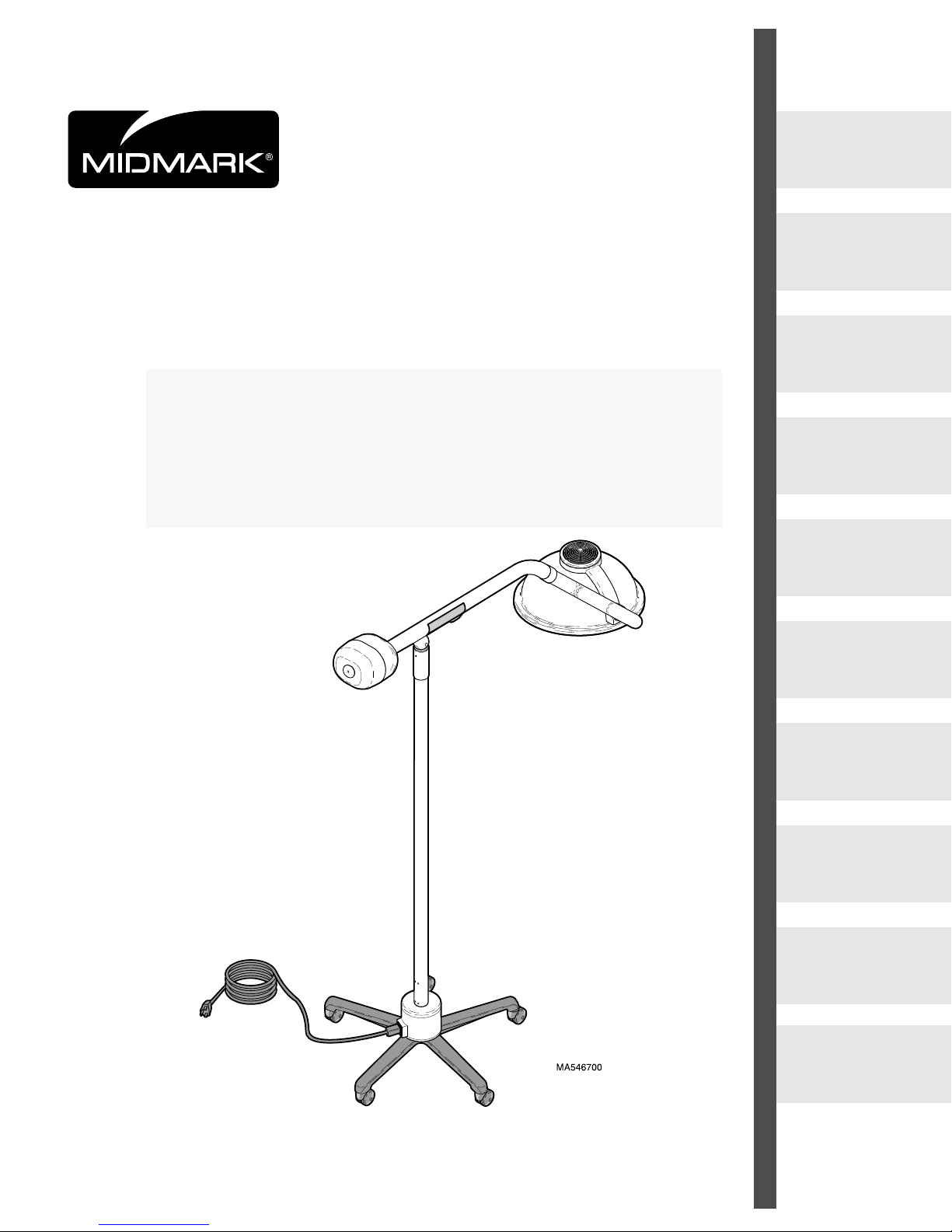
355 Mobile Lighting
System
Page 5
Description
Page 14
Components
Overview
Page 15
Controls &
Indicators
Page 16
Operation
Page 17
Operator
Maintenance
Page 18
Calling For
Service
Page 26
Specifications
Page 27
Limited
Warranty
Page 28
Page 2
MA350400
Owner’s Product Identification
(information that you will need to provide for servicing - key information is highlighted)
Date of Purchase
Serial Number
Model NumberName of Owner / Facility / Department
Name of Authorized Midmark Dealer Telephone # of Authorized Midmark Dealer
Address of Authorized Midmark Dealer
MODEL AND SERIAL
NUMBER LOCATION
MODEL NUMBER /
SERIAL NUMBER
Page 3

CONTENTS
IMPORTANT INFORMATION............................................................................................................................ 2
Scope and Purpose of This Manual ......................................................................................................... 2
Intended Use of Product........................................................................................................................... 2
Safety Instructions ....................................................................................................................................2
Transportation and Storage Conditions .................................................................................................... 2
Explanation of Safety Symbols and Notes................................................................................................ 3
INSTALLATION ................................................................................................................................................. 4
Unpacking................................................................................................................................................. 4
Necessary Tools ....................................................................................................................................... 5
Vertical Tube Installation........................................................................................................................... 6
Counterbalance Assembly Installation......................................................................................................7
Bulb Installation / Replacement Procedure .............................................................................................. 8
Housing Cap Installation........................................................................................................................... 9
Electrical Requirements.......................................................................................................................... 10
Electrical Input Setting............................................................................................................................ 10
Operational Test...................................................................................................................................... 12
DESCRIPTION ................................................................................................................................................ 13
Introduction / Features............................................................................................................................ 13
COMPONENTS OVERVIEW ........................................................................................................................... 14
CONTROLS & INDICATORS .......................................................................................................................... 15
OPERATION.................................................................................................................................................... 16
Electromagnetic Interference .................................................................................................................. 16
Operating Lighthead Assembly............................................................................................................... 16
Moving Mobile Light System ................................................................................................................... 16
OPERATOR MAINTENANCE ......................................................................................................................... 17
Operator Troubleshooting ....................................................................................................................... 17
Preventive Maintenance ......................................................................................................................... 18
Fuse Replacement Procedure................................................................................................................ 19
Ball Pivot Tension Adjustment Procedure...............................................................................................21
Cross Tube Counterbalance Adjustment ................................................................................................ 22
Cleaning and Disinfecting....................................................................................................................... 23
External Cleaning Procedures................................................................................................................ 24
External Disinfecting Procedures ........................................................................................................... 24
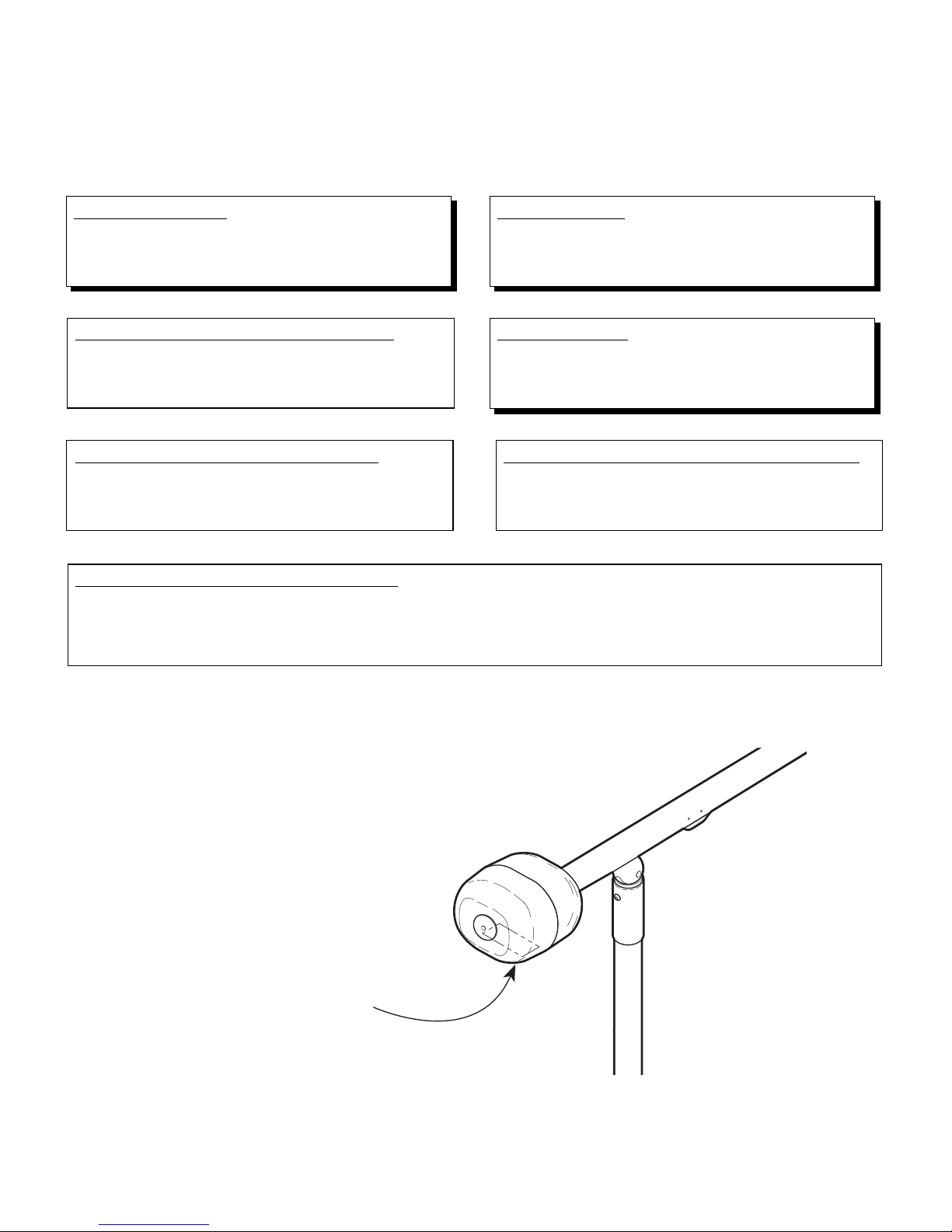
Handle Sterilization................................................................................................................................. 25
CALLING FOR SERVICE................................................................................................................................ 25
SPECIFICATIONS........................................................................................................................................... 26
LIMITED WARRANTY..................................................................................................................................... 27
Page 4

Important
Information
IMPORTANT INFORMATION
Scope and Purpose of This Manual
This manual covers complete instructions for the installation, operation, and
normal care of the 355-024, -037 Mobile Light System. It is intended that this
manual be used by any medical personnel responsible for operating the mobile
light system during a medical procedure or performing operator level
maintenance.
Intended Use of Product
This product is intended for use in all medical environments where illumination
is required for external examinations and procedures and where mobility of the
product is desired.
Safety Instructions
The primary concern of Midmark is that this equipment is operated and
maintained with the safety of the patient and staff in mind. To assure safer and
more reliable operation:
• Read and understand this manual before attempting to install or operate the
mobile light system.
• Assure that appropriate personnel are informed on the contents of this
manual; this is the responsibility of the purchaser.
• Assure that this manual is located near the light.
Transportation and Storage Conditions
• Ambient Temperature Range: ...... -30°C to +60°C (-22°F to 140°F)
• Relative Humidity ......................... 10% to 90% (non-condensing)
• Atmospheric Pressure.................. 500hPa to 1060 hPa (0.5 bar to 1.06 bars)
• This product contains glass, so it should be transported and stored with care
to limit vibration and shocks.
2
Page 5
Explanation of Safety Symbols and Notes
Indicates that the unit is rated:
Type B, Applied Part.
Indicates that the operator’s
manual should be consulted for
important information.
Indicates the presence of a
dangerous voltage / shock
hazard.
Indicates a fuse rating
specification.
V
A
Indicates a protective earth
ground.
Indicates product is fragile.
Indicates proper shipping
orientation.
Indicates that the product is
to be kept dry.
Indicates a hot surface.
DANGER
Indicates an imminently hazardous situation which, if not
avoided, will result in death or serious injury. The DANGER
symbol is limited to the most extreme situations.
WARNING
Indicates a potentially hazardous situation which, if not
avoided, could result in death or serious injury.
CAUTION
Indicates a potentially hazardous situation which, if not avoided,
may result in minor or moderate injury. It may also be used to
alert against unsafe practices.
EQUIPMENT ALERT
Indicates an imminently or potentially hazardous situation which,
if not avoided, will or may result in serious, moderate, or minor
equipment damage.
Important
Information
NOTE
Amplifies an operating procedure, practice, or condition.
3
Page 6
2
1
MA546803i
4
3
7
5
6
#10-24 x 3/8” Button Screw (4a)
1/2-20 Hex Nut (4c)
1/2” Washer (4d)
1/2” Lockwasher (4e)
Spacer Disk (4f)
Housing Cap (4h)
#10-24 x 7/8” Pan Head Screw (4b)
#10-24 x 3/8” Pan Head Screw (4i)
100 Watt Halogen Bulb (4j)
Sterilizable Handle (4k)
1/8” Hex Wrench (4g)
Installation
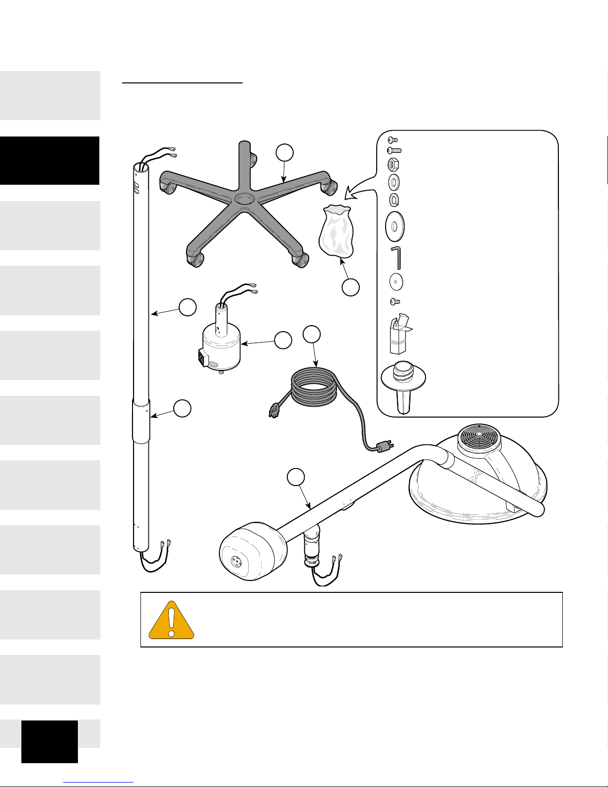
INSTALLATION
Unpacking
EQUIPMENT ALERT
To avoid damaging the light components, do not use a knife or
other sharp object to open the light’s packaging.
Carefully remove the packaging from the light components. Then inspect the
light components for any shipping damage. Report any damage to the shipping
company and fill out a concealed damage report.
4
Page 7

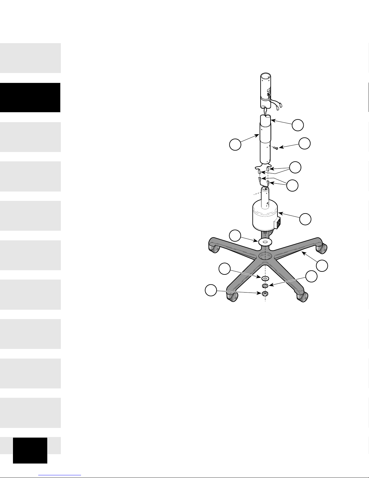
1. Cut banding and remove box lid from box.
2. Remove one base assembly (1) and inspect for damage. Check each individual caster for damage.
3. Remove one counterbalance assembly (2) and inspect for damage.
4. Remove vertical tube (3) and inspect for damage. Check that pivot sleeve
(6) is present.
5. Remove one bag (4) and inventory contents; the following items should be
included:
4a. Six #10-24 x 3/8” Button Head Screw
4b. One #10-24 x 7/8” Pan Head Screw
4c. One 1/2”-20 Hex Nut
4d. One 1/2” Flat Washer
4e. One 1/2” Lockwasher
4f. One Spacer Disk
4g. One 1/8” Hex Wrench
4h. One Housing Cap
4i. One #10-24 x 3/8” Pan Head Screw
4j. One 100 Watt Halogen Bulb
4k. One Sterilizable Handle (inspect)
6. Remove one transformer housing assembly (5) and inspect for damage.
Installation
7. Remove one power cord (7) and inspect for damage.
Necessary Tools
• 3/4 in. Socket and Ratchet Driver
• Phillips Screwdriver (medium point)
5
Page 8
MA548301i
5
4
6
1
2
8
11
3
7
10
9
Installation
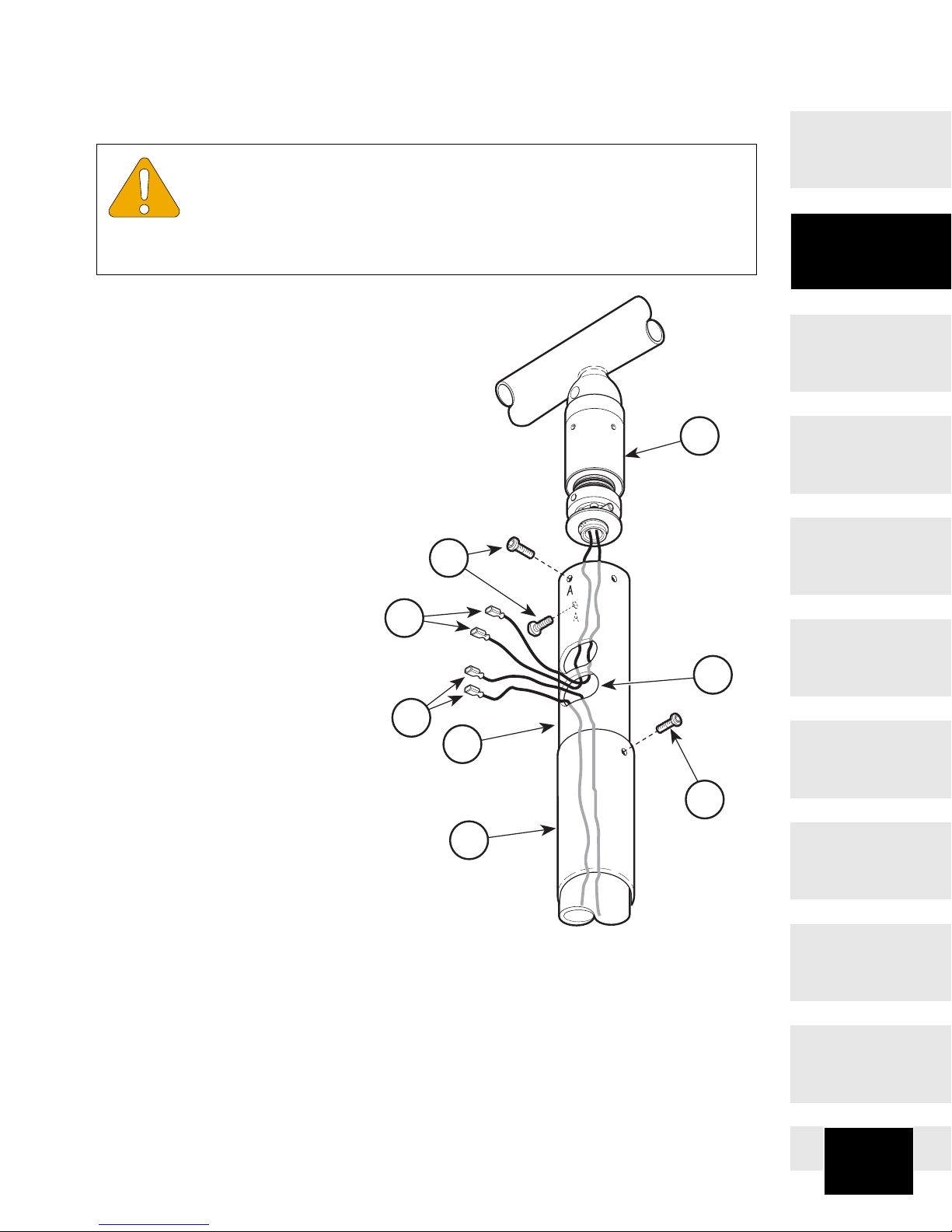
Vertical Tube Installation
1. Install spacer disk (1) on
center hole of base
assembly (2).
2. Using 3/4 in. socket
and ratchet, install
transformer housing
assembly (3) on base
assembly (2) and
secure with washer
(4), lockwasher (5),
and nut (6). Tighten
nut (6) to 35 - 45 ft-lbs
(47.5 - 61.0 N•m).
3. Remove tape securing wires
(7) to vertical tube (8) then
slide ball pivot sleeve (9) up
onto tube. Connect brown wire
(7) to brown wire (10) and blue
wire (7) to blue wire (10).
3. Using a 1/8 in. hex
wrench (supplied),
install vertical tube (8)
on mounting tube of
transformer housing
assembly (3) and
secure with four
screws (11).
6
Page 9
Counterbalance Assembly Installation
7
8
1
4
6
2
5
3
MA350700
EQUIPMENT ALERT
Make sure all three screw holes on the vertical tube (2) are
aligned with the three screw holes on the ball pivot housing of the
counterbalance assembly before installing any screws. Failure to do so could
result in damage to screw threads.
1. Align three screw holes;
then insert ball pivot housing
of counterbalance assembly
(1) into vertical tube (2) and
secure with two #10-24x3/8”
black oxide button head
screws (3), making sure to
install the two screws (3)
into the screw holes marked
with an “A”. Tighten screws
with 1/8 in. hex wrench
(supplied).
Installation
2. Pull two wires (4) from
counterbalance assembly
(1) through the bottom
access window (5).
3. Connect the brown wire (4)
to brown wire (6) and blue
wire (4) to blue wire (6).
Push wires (4 and 6) inside
the bottom access window
(5).
4. Slide ball pivot sleeve (7) up
into position and secure with
one # 10-24 x 3/8” zinc
cadmium oval head phillips
screw (8) (New Units Only,
Refer to Page 6).
7
Page 10
Bulb Installation / Replacement Procedure
4
5
Installation
2
3
6
1
EQUIPMENT ALERT
Turn the ON / STANDBY switch to STANDBY “ “ before
replacing bulb. Otherwise, electrical shock or hand burns could
result. Also, move the lighthead as far as possible from the exam / procedure
site to prevent contaminants from falling onto the exam / procedure site. Do
not try to remove the bulb until the unit is allowed to cool. Otherwise, burns to
hands and fingers will result.
A
4
B
MA381900
*
1. Turn the ON / STANDBY switch to STANDBY “ “. Move lighthead away
from the exam / procedure site. Lower the lighthead to gain access for bulb
removal.
NOTE
Screws (1) are captive screws. Only loosen captive screws; do not try to
remove them.
2. Loosen three captive screws (1) and separate top cap (2) from support arm
pivot (3).
NOTE
If new unit, remove packing material from inside of lighthead.
8
Page 11

3. Allow the bulb (4) to cool (usually for several minutes). Grasp the bulb (4)
and pull the bulb from bulb socket (5). Discard the old bulb while taking care
not to break the glass capsule of the bulb.
WARNING (*)
The maximum allowable bulb wattage which can be used in
this light is 100 Watts. There is a risk of fire or equipment
damage if 100 Watt limit is exceeded. Use Midmark P/N: 015-1357-00.
NOTE
Halogen bulbs are sensitive to body oils. Be sure not to touch the glass
portion of the bulb during relamping or cleaning. Body oils create a hot spot
on the bulb and may cause the bulb to burn out prematurely. If the glass
portion of the bulb is handled, wipe with a clean, soft, lint free cloth. Wipe with
alcohol and pat dry.
4. Using a cotton glove or similar clean cloth, grasp the new bulb (4) (supplied)
and insert the bulb into the bulb socket (5). Push the bulb in until its prongs
bottom out; there should be approximately 1/16 in. [1.6 mm] gap between
bulb socket and glass base of bulb. Forcing the bulb in further will cause
damage.
NOTE
The top cap is keyed which allows it only to be installed in one position.
Installation
5. Align the key (A) of the top cap (2) with key hole (B) in support arm pivot (3).
Then, secure top cap (2) on support arm pivot (3) by tightening three captive
screws (1). Make sure wiring (6) is tucked up above light block as much as
possible and does not hang down into path of light.
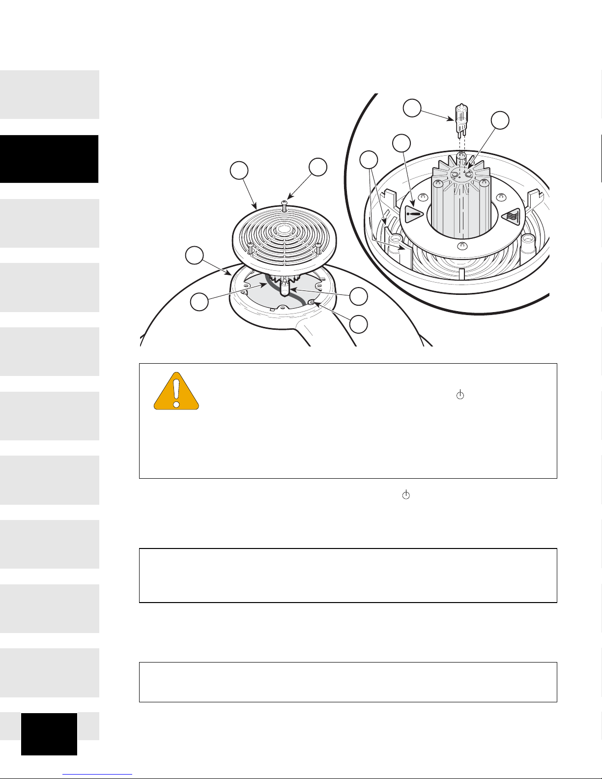
Housing Cap Installation
1. Install housing cap (2) on
ballast housing (3) and secure
with # 10-24 x 7/8” button
head screw (1). Tighten screw
using 1/8” hex wrench supplied
1
2
3
MA475300
9
Page 12

Installation
Electrical Requirements
WARNING
Use 220/230/240 VAC, 50/60 HZ alternating current only.
Failure to do so could result in electrical shock to personnel
and will result in damage to mobile light system.
NOTE
Grounding reliability can only be achieved if this equipment is connected to
an equivalent grounded receptacle.
The electrical rating for the mobile light system is 220/230/240 VAC, 50/60 Hz,
0.7 amps. The three-pronged grounding plug on the power cord must be
plugged into a matching three-pronged, grounded, correctly polarized 220/230/
240 VAC receptacle.
Electrical Input Setting
EQUIPMENT ALERT
Failure to properly determine your local voltage and / or failure to
rotate the fuse drawer until your voltage appears in the window of
the fuse drawer may result in equipment damage.
The mobile light system must be set for one of three possible voltages: 220
VAC, 230 VAC, or 240 VAC. Follow the procedure below to ensure the mobile
light system is set to match the voltage level available at your location.
1. Determine the correct voltage (220 VAC, 230 VAC, or 240 VAC) for your
location by consulting the proper local authorities.
10
Page 13

2. While simultaneously pressing inward on two locking tabs (A) with a small
flat bladed screwdriver, pull fuse drawer (1) from AC inlet (2).
4
3
Installation
B
240
230
220
2
4
A
C
1
B
A
EQUIPMENT ALERT
Be very gentle when pulling outward on two locking tabs (B). The
locking tabs are fragile and will break if pulled outward too far.
3. While simultaneously pulling out on two locking tabs (B), pull the fuse/
voltage selector (3) from fuse drawer (1).
4. Rotate the fuse/voltage selector (3) until the correct voltage for your location,
as determined in step 1, is aligned with the window (C) of fuse drawer (1).
MA382200
5. Insert the fuse/voltage selector (3) back into the fuse drawer (1) until it locks
into place. Check to make sure that the correct voltage label for your location
appears in the window (C).
11
Page 14

MA350800
Installation
6. Making sure both fuses (4) are present, insert the fuse drawer (1) into the
AC inlet (2) until it locks into place; you should hear a light clicking sound.
7. Plug one end of the power cord into AC inlet (2) and the other end into the
facility outlet receptacle.
Operational Test
1
540°
580°
35°
4
35°
1
36"
(91.4 cm)
1. Turn the ON / STANDBY switch (1) to ON “I”.
2. Observe. The lighthead (2) should illuminate.
2
3
180°
8"
(20.3 cm)
3. Position the lighthead (2) 36 in. (91.4 cm) from a table and aim the light
beam at the table.
4. Observe. There should be an evenly distributed circular pattern of bright
light, approximately 8 in. (20.3 cm) in diameter, on the table surface.
12
Page 15

5. Rotate the lighthead (2), lamp tube (3), and cross tube (4) through their
range of motions as shown on the illustration. Release the lighthead at
different positions.
6. Observe. The lighthead (2) should be able to be positioned easily through
the entire range of its motion. When the lighthead is released in any position,
no drifting should occur at any axis.
7. Turn the ON / STANDBY switch (1) to STANDBY “ “.
Installation
8. If any problems are discovered, refer to the troubleshooting guide for
adjustment and repair tips.
DESCRIPTION
Introduction / Features
The 355 lighthead assembly is a fixed-focus, faceted reflector lighthead. The
faceted reflector design provides excellent cavity penetrationwith 432 facets,
while also controlling shadows from light-blocking objects. The individual beams
of light are arranged to provide an evenly illuminated 8 in. (20.3 cm) diameter
beam at a distance of 36 in. (91.4 cm). The peak illumination at 36 in. (91.4 cm)
is 4,000 fc (43,000 lux). The optical system also filters out most of the infrared
heat from the prefocused pattern of light. The plastic handle can be easily
TM
removed for sterilization or it accepts a Devon EZ Handle
awkward adapter. The lighthead is made with a color molded, lightweight
polymer resulting in a very lightweight lighthead which is easy to position. The
arm assembly has been precisely designed, assembled, and balanced so that
the lighthead can be positioned with minimal force and no drifting. In addition,
three pivot points make the positioning of the lighthead easy and flexible.
without requiring an
Description
13
Page 16

COMPONENTS OVERVIEW
The illustration below shows the location of the light’s major components and
the chart below provides their descriptive name.
9
8
Components
Overview
5
6
12
7
4
2
11
10
1. Caster Base Assembly 8. Lighthead Assembly
2. Transformer Housing Assembly 9. Top Cap Assembly
3. AC Inlet / Fuse Drawer 10. Support Arm Pivot Assembly
4. Vertical Tube 11. Faceplate Assembly
5. Cross Tube Assembly 12. Ball Pivot Joint
6. Ballast Assembly 13. Power Cord
7. Lamp Tube Assembly
14
13
1
3
DESCRIPTION OF COMPONENTS
Page 17

CONTROLS & INDICATORS
MA382100
The following illustration shows the location of the light’s controls and indicators
and the chart below describes their function.
1
540°
580°
1
35°
35°
2
3
180°
Controls &
Indicators
Ref. Control / Indicator Function
1
2 fuse drawer
3 sterilizable handle allows sterile personnel to move lighthead.
on / standby switch (on
“I” / standby “ “)
turns the light on or off.
can be removed and inspected to determine if
fuse has been blown, indicating a current
surge or problem with light.
15
Page 18

Operation
OPERATION
Electromagnetic Interference
This product is designed and built to minimize electromagnetic interference with
other devices, however, if interference is noticed between another device and
this product, remove the interfering device from the room or plug this product
into an isolated circuit.
WARNING
Risk of fire and/or equipment damage. Do not obstruct the
airflow of the lighthead.
If the 355 mobile light system malfunctions, immediately turn the ON /
STANDBY switch to STANDBY “ ” and unplug the power cord.
Operating Lighthead Assembly
Turn the lighthead on by switching the ON / STANDBY switch to ON “I”. To
adjust the position of the lighthead, grasp the sterile handle (3) and rotate the
arm assembly and lighthead as necessary to obtain correct light position on the
patient (See previous figure for amount of rotation for an axis). To turn off the
lighthead, switch the ON / STANDBY switch to STANDBY “ “.
Moving Mobile Light System
WARNING
The mobile light system is very stable when it is stationary
and when pushed on smooth surfaces. However, when the
mobile light system is being transported, it can become susceptible to
tipping when it is pushed over a threshold or other similar obstruction.
Failure to use care when navigating over thresholds, obstructions, or
carpet could result in the mobile light system tipping and causing
severe personal injury or damage to mobile light system. Grasping the
vertical tube at waist height or lower during movement will help
stability during movement.
To move the mobile light system to a new area or room, simply unplug the light’s
power cord from the outlet receptacle, coil and hold power cord, and then
grasping the vertical tube at approximately waist height or lower, push the
mobile light system to desired area.
16
Page 19

OPERATOR MAINTENANCE
Operator Troubleshooting
Problem Possible Cause Solution
no light from lighthead
no light from lighthead; on /
standby switch is on “ I”
no light from lighthead
although the bulb and fuses
were checked; lighthead
flashes intermittently when
lighthead or arms are moved
lamp tube or lighthead does
not rotate freely or drifts when
released in desired position
lighthead is on standby
““
bulb has burned out or
has not been installed
fuse is blown (open)
no power to the
transformer housing
assembly
transformer is
malfunctioning
circuit or wiring problem
within arm assemblies,
transformer housing
assembly, or other part of
lighting system
brakes for the suspect
axis need adjustment
turn on / standby switch
to on “ I”
refer to bulb installation
procedure in this manual
refer to the fuse
replacement procedure
in this manual
check to make sure
power cord is plugged
in. Then call your
building maintenance
electrician to check for
facility power at the
electrical receptacle.
call Midmark Technical
Support: 1-800-Midmark
call Midmark Technical
Support: 1-800-Midmark
call Midmark Technical
Support: 1-800-Midmark
Operator
Maintenance
cross tube rotates (at ball pivot
joint) too stiffly or drifts when
released in desired position
squeak coming from
movement of the ball pivot.
tension needs to be
adjusted or cross tube
counterbalance needs to
be adjusted
residue build-up on ball
pivot
refer to tension
adjustment procedure in
this manual. If proper
tension cannot be
achieved, call Midmark
Technical Support: 1800-Midmark.
Lower the ball pivot
sleeve. Wipe the ball
pivot with a clean, dry
rag. Reinstall the ball
pivot sleeve.
17
Page 20

Preventive Maintenance
The following preventive maintenance schedule should be followed. If and when
problems are detected, refer to the troubleshooting guide in this manual.
FREQUENCY ACTIVITY
monthly Inspect casters for breaks, cracks, or wear. Replace
casters as necessary.
semiannually Inspect rotation of lighthead. Make sure the lighthead
rotates freely, without noise, and has 180° of rotation at
lamp tube connection. Make sure the lighthead stays positioned at any point (without drifting) with respect to the
lamp tube. See figure in the Controls & Indicators section.
semiannually Inspect the rotation of the lamp tube and cross tube. Make
sure the arm assembly rotates freely and without noise.
Make sure the arm assembly doesn’t drift at any point in
its range of motion. The lamp tube should have 540° of
rotation at cross tube connection. The cross tube should
have 580° of rotation at vertical tube connection and
should also have a vertical range of motion from -35° to
+35°. See figure in the Controls & Indicators section.
Operator
Maintenance
semiannually Turn light ON. Rotate lighthead, lamp tube, and cross
tube while observing lighthead. Lighthead should not
intermittently flicker or stop illuminating while joints are
being rotated.
semiannually Check for excessive joint rotation (more than 540° of
rotation at lamp tube connection or 580° of rotation at
cross tube connection). If there is excessive rotation, the
physical stops for an axis may be broken.
semiannually Inspect faceplate and inside of lighthead for indications of
broken material or other signs of damage. If damage to
any part of lighthead is evident, do not continue to use
lighthead. Using lighthead with a broken IR filter could
result in tissue burns to patients.
semiannually Inspect lighthead for excessive dust or grime buildup in
lighthead interior. Do not attempt to clean or disinfect;
instead call an authorized dealer or service technician.
Semiannually Move the cross tube up and down while listening for
squeaks coming from the ball pivot area. If squeaks are
heard, lower the ball pivot sleeve and wipe the ball pivot
sleeve with a clean, dry rag (wipe even if ball pivot
appears clean). Repeat the test. If no squeaks are heard,
reinstall the ball pivot sleeve.
18
Page 21

Fuse Replacement Procedure
230
240
220
2
3
A
A
1
230
3
MA38510
1. Turn the ON / STANDBY switch to standby “ ” and unplug light power cord
from AC inlet (2).
2. While simultaneously pressing inward on two locking tabs (A) with a small
flat bladed screwdriver, pull fuse drawer (1) from AC inlet (2).
3. Pull two fuses (3) out of fuse drawer (1).
4. Inspect fuses (3) for any indication that they have blown (opened); i.e. burnt
look, discolored, fuse cord melted through, etc. Discard fuse(s).
EQUIPMENT ALERT
Use fuses of the same voltage rating, amperage rating, and type.
Failure to do so could result in damage to the mobile light
assembly.
Operator
Maintenance
19
Page 22

5. Obtain new fuse(s) (3) of the same voltage rating, amperage rating, and
type. Refer to the SPECIFICATIONS section in this manual for the fuse
specification.
6. Insert the fuse drawer (1) into the AC inlet (2) until it locks into place; you
should hear a light clicking sound.
7. Plug light power cord into AC inlet (2), turn ON / STANDBY switch to ON “I”,
and check for light output. If fuse blows again, call for service (see calling for
service in this manual).
Operator
Maintenance
20
Page 23

Ball Pivot Tension Adjustment Procedure
2
ASSEMBLY / DISASSEMBLY
POSITION
LIGHT TENSION
POSITION
MEDIUM TENSION
POSITION
STIFF TENSION
POSITION
CRAFTSMAN
1
3
4
5
MA3509
ASSEMBLY / DISASSEMBLY
POSITION
LIGHT TENSION POSITION
MEDIUM TENSION POSITION STIFF TENSION POSITION
1. Remove screw (1) and slide ball pivot sleeve (2) down out of way.
2. Rotate cross tube (3) until adjustment hole (4) appears in the adjustment
window opening.
NOTE
There are three settings which the ball pivot cam (5) can be set for: light
tension, medium tension, or stiff tension (see above figure). These settings
may be changed according to the operator’s preference.
3. Insert a phillips screwdriver into adjustment hole (4). Then, using the
screwdriver, rotate ball pivot cam (5) to the desired tension setting.
4. Remove the screwdriver and move the cross tube (3) about the ball pivot
joint in a circular motion and up and down motion to ensure the setting is the
one desired. Move the cross tube (3) to a horizontal position and release it.
The cross tube should not drift in any direction. If it does, a higher tension
setting is required or the cross tube counterbalance needs adjusted (see
counterbalance adjustment in this manual). Repeat steps 3 and 4 until the
desired tension adjustment is achieved with no drifting of the cross tube.
Operator
Maintenance
5. Slide ball pivot sleeve (2) up into position and secure with screw (1).
21
Page 24

Cross Tube Counterbalance Adjustment
3
2
1
Operator
Maintenance
4
1. Remove screw (1, see previous figure) and slide ball pivot sleeve (2) down
out of way.
2. Rotate cross tube (3, see previous figure) until adjustment hole (4) appears
in the adjustment window opening.
3. Insert screwdriver into adjustment hole (4, see previous figure). Then, using
the screwdriver, rotate ball pivot cam (5) to the assembly / disassembly
setting. Remove the screwdriver.
4. Remove screw (1, see figure above) and housing cap (2) from ballast
housing (3).
MA351000
NOTE
One way to determine if cross tube is balanced properly is to raise the cross
tube above the horizontal plane, release it, and observe where it stops. Then,
lower the cross tube below the horizontal plane, release it, and observe
where it stops. The cross tube should return to the horizontal position and
remain there; if it does, the cross tube counterbalance is adjusted properly.
Turning screw (4) in clockwise direction will raise the lighthead end of the
cross tube. Turning screw (4) in counterclockwise direction will lower the
lighthead end of cross tube.
22
Page 25

5. Using a 3/16” hex (Allen) wrench, adjust screw (4) until cross tube (5)
balances in a horizontal position.
6. Install housing cap (2) on ballast housing (3) and secure with screw (1).
NOTE
It is recommended that you start with the light setting and then proceed to the
medium or stiff setting only if necessary to prevent drifting.
7. Insert screwdriver into adjustment hole (4, see figure of previous paragraph).
Then, using the screwdriver, rotate ball pivot cam (5) to the light, medium, or
stiff setting as desired by the operator(s). Remove screwdriver.
8. Slide ball pivot sleeve (2) up into position and secure with screw (1).
Cleaning and Disinfecting
EQUIPMENT ALERT
When cleaning or disinfecting the light, remove power from the
light, allow optical unit to cool, and do not touch glass portion of
bulb or inner components of lighthead with bare hand. Clean EXTERNAL
SURFACES ONLY (arm assemblies and lighthead). Prevent fluids from
leaking into interior or onto electrical contacts. DO NOT ATTEMPT to clean
or disinfect interior; instead call an authorized dealer or service technician.
EQUIPMENT ALERT
Use only quaternary disinfectants to disinfect light. Staining,
pitting, discoloration, or softening could occur if phenolic,
iodophor, or glutaraldehyde-based disinfectant is used on plastic surfaces of
the lighthead. Also, use of alcohol or aerosol spray cleaner / disinfectant
containing substantial amounts of alcohol in the formula can damage the
faceplate.
Operator
Maintenance
23
Page 26

External Cleaning Procedures
For general cleaning, use a mild detergent and water solution. Wring excess
solution from sponge or cloth before wiping.
According to your facility’s procedure:
1. Clean faceplate with an antistatic acrylic cleaning solution using a soft, clean
cloth. Do not use alcohol or abrasive compounds on faceplate.
2. Wipe external surface of arm assemblies and lighthead with a mild detergent
and water solution.
3. Rinse all external surfaces with a soft cloth and clear water, wringing excess
from cloth before wiping.
4. Wipe all external surfaces dry.
External Disinfecting Procedures
Operator
Maintenance
According to your facility’s procedure:
1. Use only quaternary disinfectants to disinfect light. Staining, pitting,
discoloration, or softening could occur if phenolic, iodophor, or
glutaraldehyde-based disinfectant is used on plastic surfaces of the
lighthead. Also, use of alcohol or aerosol spray cleaner / disinfectant
containing substantial amounts of alcohol in the formula can damage the
faceplate.
2. Wring excess solution from cloth.
3. Using soft cloth, wipe all external surfaces of arm assemblies and lighthead.
4. Do not rinse or dry external surfaces. Allow germicidal solution to air dry.
24
Page 27

Handle Sterilization
Acceptable Acceptable Unacceptable
• Use only steam sterilization on the handle.
• To sterilize, process the handle in a dynamic air removal steam sterilizer
(sterilizer that uses pressure pulses and / or vacuum purges to remove air
from the chamber) at a temperature of 132°C (270°F) for 4 minutes
minimum. If using a Midmark M9 or M11 sterilizer use the “Pouches” cycle. It
is recommended that the handle be pouched or wrapped for sterilization to
maintain its sterility until placed on the light. When pouching or wrapping the
handle, use only sterilizer pouches or wraps that have been cleared by the
FDA and labeled for use with steam sterilization cycle parameters (e.g.
temperature and exposure time) of the sterilization cycle being used. Place
the handle on the sterilizer tray so steam can enter the opening and air and
any steam condensate can drain from the handle (refer to illustration).
.
CAUTION
The handle is not sterile when shipped so if your application
requires the handle to be sterile, it must be sterilized before initial
use or covered with a sterile protective barrier.
CALLING FOR SERVICE
If you are having a problem or have a question, refer to the inside front cover of
this manual and call your dealer. Make sure that you have the information that is
highlighted on the inside front cover of this manual available. If you can’t resolve
your question or problem with your dealer, call the following number:
1-800-Midmark (1-800-643-6275) or 937-526-3662
8:00 a.m until 5:00 p.m. (Eastern Standard Time in the U.S.)
Monday thru Friday, except for standard U.S. holidays.
Operator
Maintenance
Calling For
Service
25
Page 28

Specifications
SPECIFICATIONS
Model 355 Mobile Light
Beam diameter @ 91 cm:.............. 20 cm (8 in.) (defined by 20% of peak
illumination)
Bulb: ............................................... 24 VAC, 100 W halogen bulb
Color temperature:........................4,200K
Diameter of lighthead: ..................43 cm (17 in.)
Focal length: .................................. 91 cm (36 in.)
Illumination @ 60.9 cm (24 in.):....53,800 lux / 5000 fc
Illumination @ 91.4 cm (36 in.):....36,600 lux / 3400 fc
Refecting facets............................. 432
Electrical requirement: .................220, 230, or 240 VAC, 50 / 60 HZ,
0.7 amps, single phase
“A” Reach of arm assemblies:.....66 cm (26 in.) maximum from centerline of
vertical tube to center of lighthead.
“B” Length of counterbalance: ....122 cm (48 in.)
“F” Diameter of caster base: ........71 cm (28 in.)
“E” Minimum lighthead height:.... less than 112 cm (44 in.)
“D” Maximum lighthead height:... greater than 188 cm (74 in.)
“C” Maximum overall height: .......less than 218 cm (86 in.)
Rotation of lighthead: ...................180° rotation at lamp tube connection
Rotation of lamp tube: .................. 540° rotation at cross tube connection
Rotation of cross tube: .................580° rotation at vertical tube connection
Vertical range of cross tube: ........-35° to +35° vertical movement
Box dimensions:............................154.9 cm “L” x 77.5 cm “W” x 26.7 cm “H”
61in. “L” x 30.5 “W” x 10.5 “H”
Unboxed weight:....26.8 kg (59.0 lbs)
Power cord .............Harmonized cordage,
2.44 m (96 in.) long
with hospital grade
grounding type plug.
Classifications: ......Class 1, Type B
applied part, Ordinary
Equipment,
Continuous Operation
Fuse Rating:...........0.8 amp, 250 VAC,
5 x 20 mm, Type FST
Time Lag IEC 127-2/3
Equipment not suitable for use in the
presence of a flammable anesthetic
mixture with air, oxygen, or nitrous
oxide.
26
Page 29

LIMITED WARRANTY
SCOPE OF WARRANTY
Midmark Corporation (“Midmark”) warrants to the original purchaser its new
Alternate Care products and components (except for components not warranted
under “Exclusions”) manufactured by Midmark to be free from defects in material
and workmanship under normal use and service. Midmark’s obligation under this
warranty is limited to the repair or replacement, at Midmark’s option, of the parts or
the products the defects of which are reported to Midmark within the applicable
warranty period and which, upon examination by Midmark, prove to be defective.
APPLICABLE WARRANTY PERIOD
The applicable warranty period, measured from the date of delivery to the original
user, shall be one (1) year for all warranted products and components.
EXCLUSIONS
This warranty does not cover and Midmark shall not be liable for the following: (1)
repairs and replacements because of misuse, abuse, negligence, alteration,
accident, freight damage, or tampering; (2) products which are not installed, used,
and properly cleaned as required in the Midmark “Installation” and or “Installation /
Operation Manual for this applicable product. (3) products considered to be of a
consumable nature; (4) accessories or parts not manufactured by Midmark; (5)
charges by anyone for adjustments, repairs, replacement parts, installation, or other
work performed upon or in connection with such products which is not expressly
authorized in writing in advance by Midmark.
EXCLUSIVE REMEDY
Midmark’s only obligation under this warranty is the repair or replacement of
defective parts. Midmark shall not be liable for any direct, special, indirect,
incidental, exemplary, or consequential damages or delay, including, but not limited
to, damages for loss of profits or loss of use.
NO AUTHORIZATION
No person or firm is authorized to create for Midmark any other obligation or liability
in connection with the products.
THIS WARRANTY IS MIDMARK’S ONLY WARRANTY AND IS IN LIEU OF ALL
OTHER WARRANTIES, EXPRESS OR IMPLIED. MIDMARK MAKES NO
IMPLIED WARRANTIES OF ANY KIND INCLUDING ANY WARRANTIES OF
MERCHANTABILITY OR FITNESS FOR ANY PARTICULAR PURPOSE. THIS
WARRANTY IS LIMITED TO THE REPAIR OR REPLACEMENT OF DEFECTIVE
PART S.
SF-1487 REV. A1
Warranty
27
Page 30

NOTES:
28
Page 31

NOTES:
29
Page 32

Midmark Corporation
60 Vista Drive
Versailles, OH 45380 USA
1-800-643-6275
1-937-526-3662
www.midmark.com
Language of origin: English
© Midmark Corporation - 1999
003-1058-00 Rev. K (3/3/12)
 Loading...