

Midmark 255, 255-021, 255-022, 255-026, 255-025 User Manual
...
Style P
255
LED Procedure Light
For Models:
Ceiling: 255 (-021 to -024)
Mobile 255 (-025 / -027)
Wall: 255 (-026)
User’s Guide
003-2848-99 Rev AA4 (1/9/19)
TP202 20-42-FO-00014 Rev A1 C2169
User’s Guide
English
Español
Français
© Midmark Corporation 2016
003-2848-99
TP202 20-42-FO-00014 Rev A1 C2169
English - 2
Model / Serial Number:
Date of Purchase:
Midmark Authorized Service
Company:
Dealer :
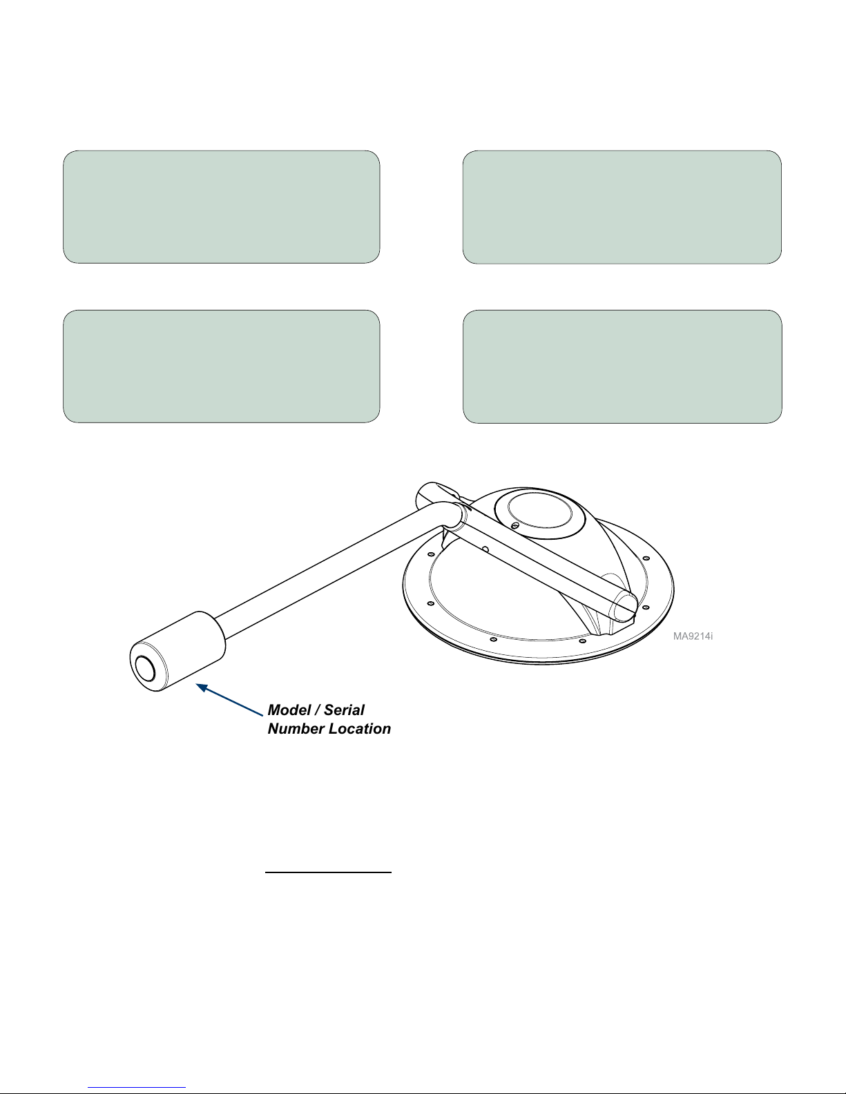
Product Information
Model / Serial
Number Location
Basic Cross Tube/
Lighthead shown
Product Registration
To register your product, go to www.midmark.com.

© Midmark Corporation 2016
003-2848-99
TP202 20-42-FO-00014 Rev A1 C2169
English - 3
Table of Contents
Important Information
Safety Symbols ......................................................................................................................4
Intended Use ..........................................................................................................................5
Electromagnetic Interference ...............................................................................................5
Disposal of Equipment ..........................................................................................................5
Transportation / Storage Conditions ...................................................................................5
Operation
Power & Adjustment Switches .............................................................................................6
Positioning the Lighthead .....................................................................................................7
Maintenance
Preventative Maintenance....................................................................................................8
Cleaning & Disinfecting .............................................................................................. 9
Sterilizing the Handle .......................................................................................................... 11
Replacing the Fuses:
Ceiling Mounted Lights .....................................................................................................12
Wall Mounted Lights ..........................................................................................................13
Mobile Lights .....................................................................................................................14
Ball Pivot Tension Adjustment ...........................................................................................15
Cross Tube Counterbalance Adjustment .................................................................. 16
Specications
Specications Chart ............................................................................................................17
Dimensions / Range of Motion:
Ceiling Mounted Lights .....................................................................................................20
Wall Mounted Lights ..........................................................................................................21
Mobile Lights .....................................................................................................................22
Model Identication / Compliance
Model Identication / Compliance Chart ..........................................................................23
Warranty Information
Limited Warranty .................................................................................................................25

© Midmark Corporation 2016
003-2848-99
TP202 20-42-FO-00014 Rev A1 C2169
English - 4
Proper Shipping
Orientation
Fragile
Keep Dry
Fuse Rating Specication
Protective Earth Ground
Type B, Applied Part
Refer to instruction manual/booklet
Maximum stacking height
(Refer to “n” number on
package.
Transportation Orientation
Atmospheric Pressure
Relative Humidity
100 F
38 C
23 F
-5 C
Transportation & Storage
Temperature
Important Information - Safety Symbols
WARNING
Indicates a potentially hazardous situation which could result in serious injury.
Caution
Indicates a potentially hazardous situation which may result in minor or moderate injury. It
may also be used to alert against unsafe practices
Equipment Alert
Indicates a situation which could result in equipment damage.
Note
Amplifies a procedure, practice, or condition.
Symbol Glossary
These symbols may appear on your equipment and/or in the manuals.
Manufacturer
Serial Number
Catalogue Number

© Midmark Corporation 2016
003-2848-99
TP202 20-42-FO-00014 Rev A1 C2169
English - 5
Intended Use
This product is intended to be used in medical environments where illumination is required for medical use
during external examinations and procedures.
Electromagnetic Interference
This product is designed and built to minimize electromagnetic interference with other devices. However, if
interference is noticed between another device and this product:
• Remove interfering device from room
• Plug light into isolated circuit
• Increase separation between light and interfering device
• Contact Midmark if interference persists
Authorized EU Representative
Countries in the EU should direct all questions, incidents, and complaints to Midmark’s Authorized EU
representative listed below:
Newmed Srl.
Via Lenin 79/A
Quattro Castella (RE), 42020, Italy
Phone: +39.0522.875.166
Fax: +39.0522.243.096
Disposal of Equipment
At the end of product life, the light, accessories, and other consumable goods may become contaminated
from normal use. Consult local codes and ordinances for proper disposal of equipment, accessories and
other consumable goods.
Transportation / Storage Conditions
Ambient Temperature Range: ....................................................................-30°C (-22°F) to 60°C (140°F)
Relative Humidity...................................................................................................................10% to 90%
Atmospheric Pressure ...........................................................500 hPa (15 in.Hg) to 1060 hPa (31 in.Hg)
Operation Conditions
Ambient Temperature Range: ....................................................................10°C (50°F) to +40°C (104°F)
Relative Humidity...................................................................................................................30% to 75%
Atmospheric Pressure ...........................................................700 hPa (20 in.Hg) to 1060 hPa (31 in.Hg)
© Midmark Corporation 2016
003-2848-99
TP202 20-42-FO-00014 Rev A1 C2169
English - 6
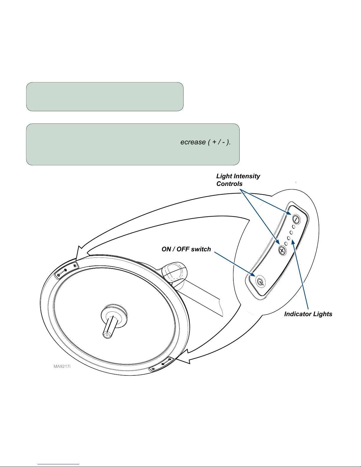
Operation
Power and Adjustment Switches
To turn the light ON / OFF...
Press the power button ( ).
O
I
ON / OFF switch
Light Intensity
Controls
To adjust the light...
Press the light intensity controls to increase / decrease ( + / - ).
Note: Indicator lights show current settings.
Indicator Lights
© Midmark Corporation 2016
003-2848-99
TP202 20-42-FO-00014 Rev A1 C2169
English - 7
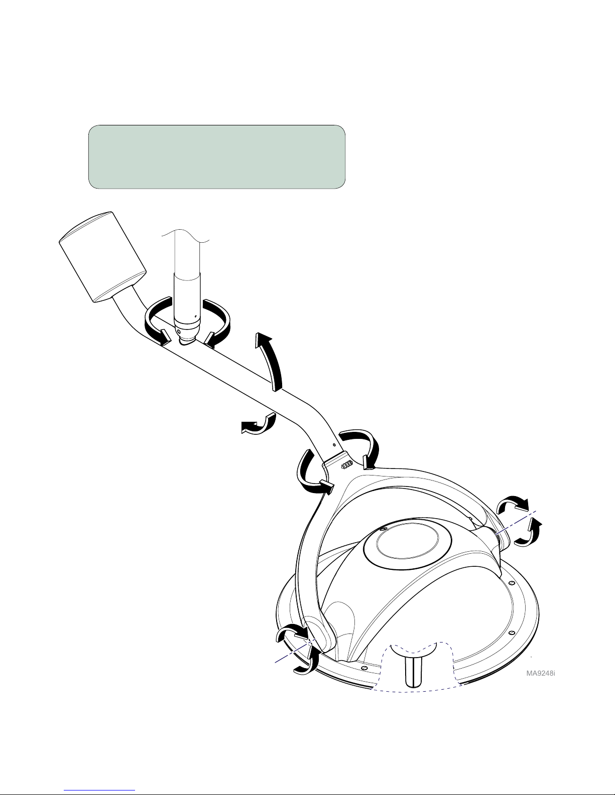
Positioning the Lighthead
To position the lighthead...
Grasp the sterilizable handle, then rotate
the arm / lighthead to desired position.
Ceiling / Wall model shown
Mobile model is similar.

© Midmark Corporation 2016
003-2848-99
TP202 20-42-FO-00014 Rev A1 C2169
English - 8
Maintenance
Calling for Service
If service is required, contact your authorized Midmark dealer.
To contact Midmark directly:
1-800-MIDMARK (1-800-643-6275)
8:00 am until 5:00 p.m. Monday - Friday (EST)
www.midmark.com
Preventative Maintenance
Periodically inspect the following areas:
• Power cord(s) should be free of cuts or other visible damage.
• All fasteners should be in place and tightened securely.
• All mechanical functions should operate properly.
Have an authorized service technician inspect your equipment every six months.
Frequency Activity
Semi-annually Inspect rotation of lighthead / arms at all pivot points.
Arms should move freely, without noise. Arms should not drift when released.
Check for excessive rotation. (This would indicate internal stops may be broken).
Use the Range of Motion section in this manual as a reference.
Turn light ON. Rotate lighthead / arms at all pivot points.
Light should not icker or ash at any time.
Inspect the faceplate and inside of the lighthead for signs of damage.
Inspect lighthead for excessive dust or dirt buildup inside lighthead.
Do not attempt to clean interior - contact an authorized service technician.
Note
Model / serial number information is required when calling for service.
© Midmark Corporation 2016
003-2848-99
TP202 20-42-FO-00014 Rev A1 C2169
English - 9
Maintenance
Cleaning & Disinfecting
Equipment Alert
Use only quaternary disinfectants on light. Staining, pitting, discoloration, or softening could
occur if phenolic, iodophor, or glutaraldehyde-based solution is used on plastic surfaces of
the lighthead. Also, using alcohol or aerosol spray cleaners / disinfectants containing substantial amounts
of alcohol in the formula may damage the lens.
WARNING
• Always disconnect power before cleaning / disinfecting.
• Prevent fluids from leaking into interior or onto electrical contacts.
• Clean EXTERNAL SURFACES ONLY (arm assemblies / lighthead).
• Do NOT attempt to clean / disinfect internal surfaces. Contact an authorized service technician.
Equipment Alert
Follow current National Guidelines for Disinfection & Sterilization in Healthcare Facilities.
Caution
The light and surrounding components may be HOT! Allow the light to cool for at least
five minutes before contacting surfaces. Never operate the light with faceplate removed.
© Midmark Corporation 2016
003-2848-99
TP202 20-42-FO-00014 Rev A1 C2169
English - 10
Painted Metal / Plastic Surfaces
Clean the painted metal and plastic surfaces weekly using a clean soft cloth, and mild cleaner.
To disinfect external surfaces...
A) Apply appropriate disinfecting solution (see EQUIPMENT ALERT) to soft cloth.
B) Wring excess solution from cloth, then wipe external surfaces of arms / lighthead.
C) Do not rinse or dry. Allow solution to air dry.
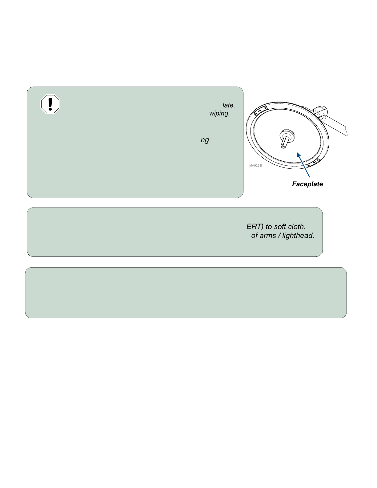
Equipment Alert
Do not use alcohol or abrasive compounds on faceplate.
Wring excess water / solution from cloth before wiping.
To clean external surfaces...
A) Clean faceplate with an antistatic acrylic cleaning
solution using a soft, clean, cloth.
B) Wipe external surfaces of arms / lighthead with a
mild detergent and water solution.
C) Rinse all surfaces with a soft cloth and clean water.
D) Wipe all surfaces dry.
Faceplate
To clean faceplate...
Use an antistatic acrylic cleaning solution (ex: Brillianize) or an LCD screen cleaner (ex: Klear Screen).
The solution should be free of ammonia, carbon tetrachloride, and acetone. After softly blowing away
free debris and dust, apply the cleaning product with a non-abrasive, lint-free cloth or microber cloth.
Cleaning & Disinfecting (continued)
© Midmark Corporation 2016
003-2848-99
TP202 20-42-FO-00014 Rev A1 C2169
English - 11
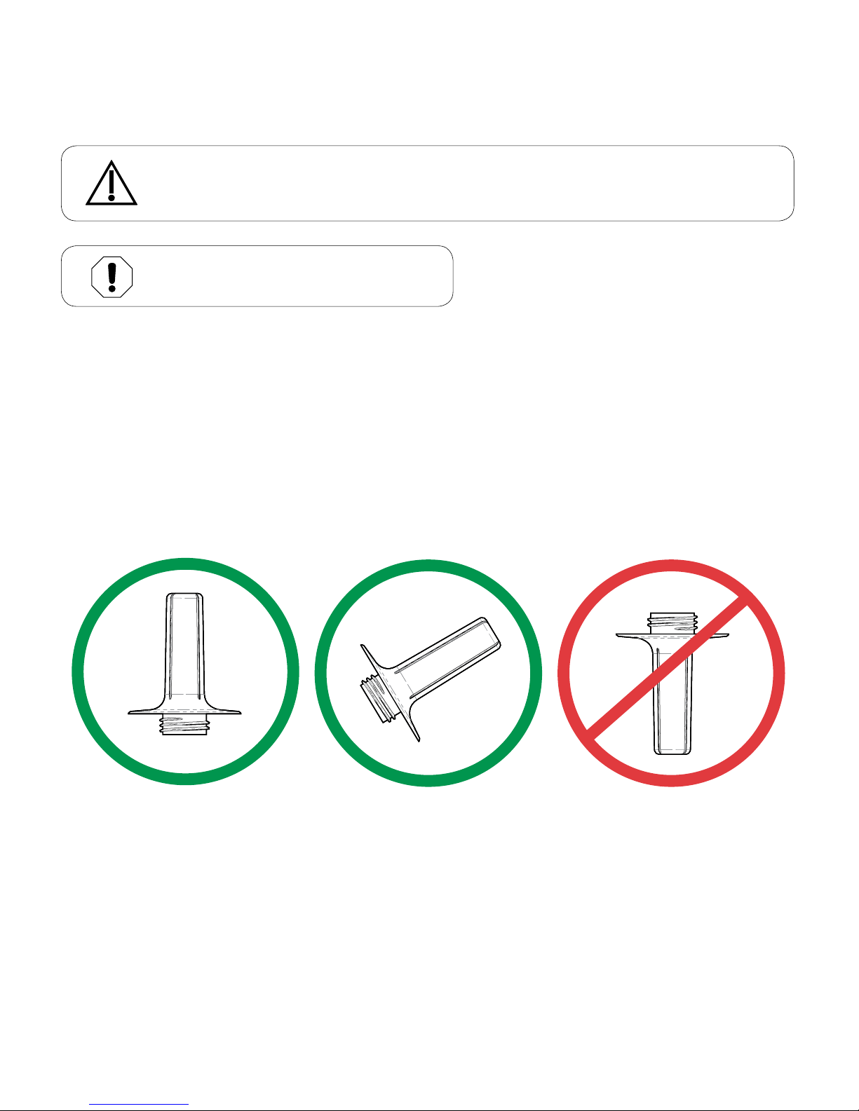
Sterilizing the Handle
To sterilize, process the handle in a dynamic air removal steam sterilizer (sterilizer that uses pressure
pulses and / or vacuum purges to remove air from the chamber) at a temperature of 270° F (132° C) for four
minutes minimum. If using a Midmark M9 or M11 sterilizer, use the “POUCHES” cycle. It is recommended
that the handle be pouched or wrapped for sterilization to maintain its sterility until placed on the light. When
pouching or wrapping the handle, use only sterilizer pouches or wraps that have been cleared by the FDA
and labeled for use with the steam sterilization cycle parameters (e.g. temperature and exposure time) of the
sterilization cycle being used. Place the handle on the sterilizer tray so steam can enter the opening and air
and any steam condensate can drain from the handle (see illustration below).
Equipment Alert
Use only steam sterilization on the handle.
MA8156i
Caution
The handle is not sterile when shipped. If your application requires the handle to be sterile,
it must be sterilized before use, or covered with a sterile protective barrier.
© Midmark Corporation 2016
003-2848-99
TP202 20-42-FO-00014 Rev A1 C2169
English - 12
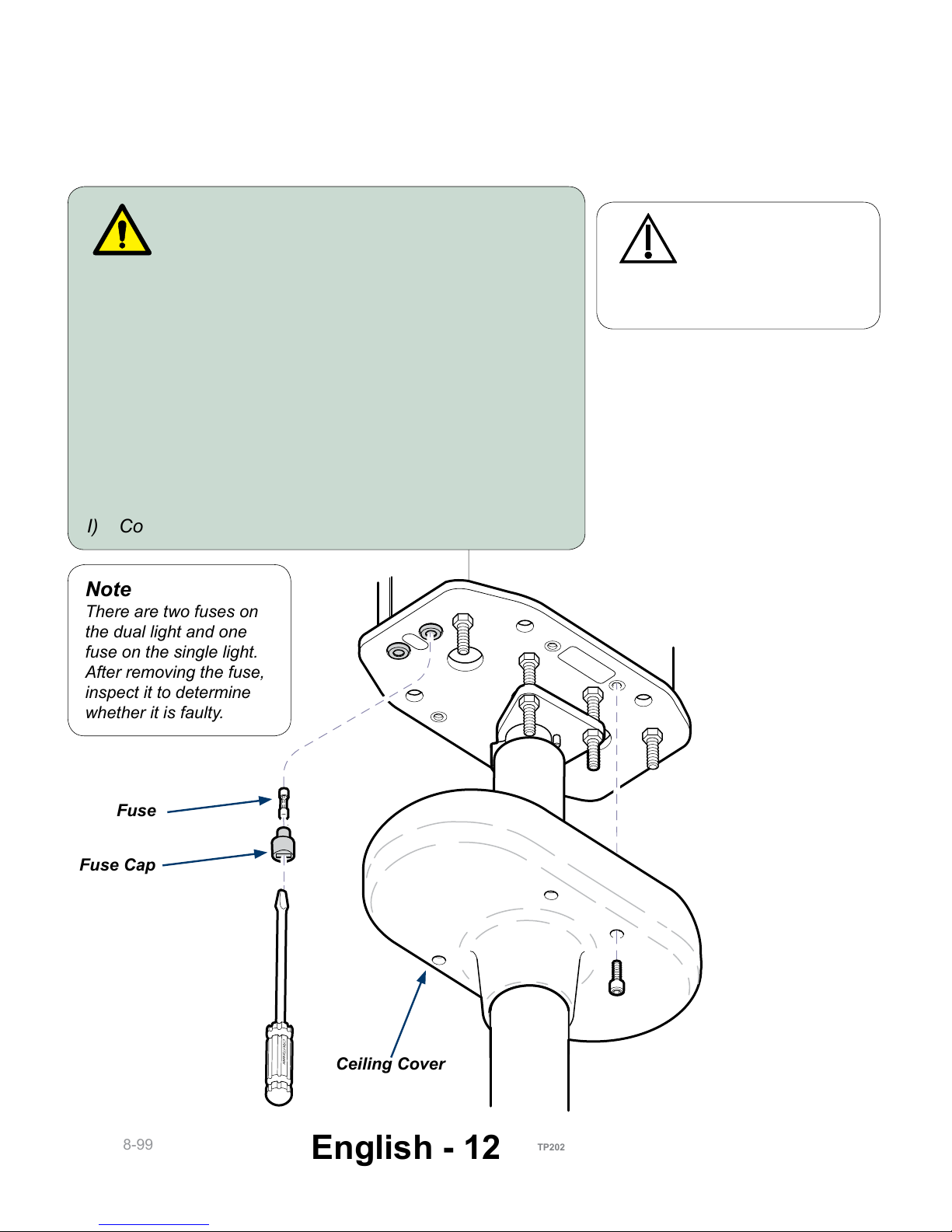
Replacing the Fuses
Ceiling Mounted Lights
CRAFTSMAN
Note
There are two fuses on
the dual light and one
fuse on the single light.
After removing the fuse,
inspect it to determine
whether it is faulty.
Caution
To completely isolate
the light from electrical
mains supply, the circuit breaker
must be turned off.
Warning
Always disconnect power before replacing fuses.
To install fuses...
A) Turn light OFF ( ).
B) Disconnect power from light.
C) Remove four screws, then lower ceiling cover.
D) Using a flat-bladed screwdriver, rotate fuse cap
counter-clockwise 1/4 turn, while pushing upward.
E) Pull fuse out of fuse cap. See Note.
F) Insert new fuse into fuse cap.
G) Using a flat-bladed screwdriver, rotate fuse cap
clockwise 1/4 turn, while pushing into fuse socket.
H) Install ceiling cover.
I) Connect power and verify operation.
O
I
Fuse Cap
Fuse
Ceiling Cover
© Midmark Corporation 2016
003-2848-99
TP202 20-42-FO-00014 Rev A1 C2169
English - 13
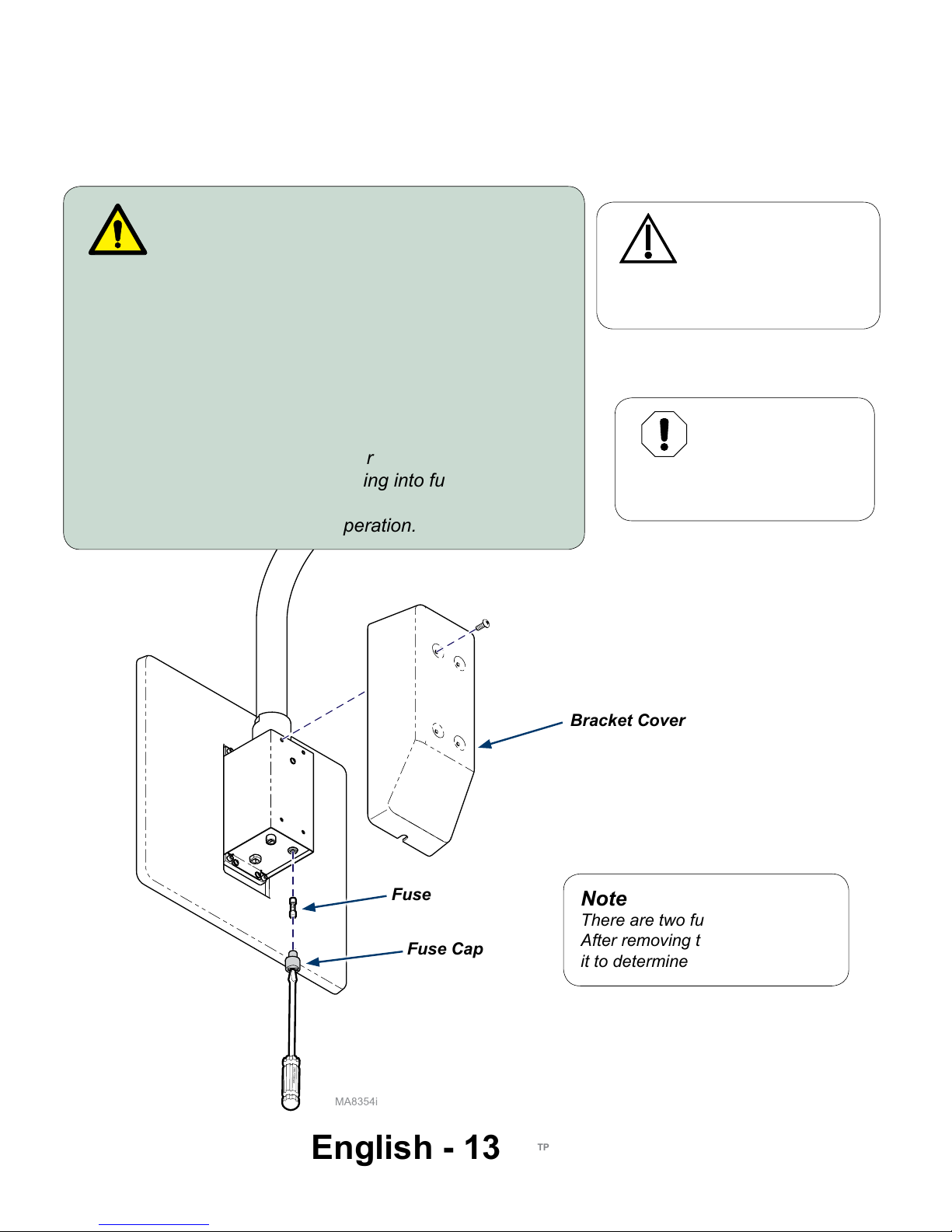
Replacing the Fuses - continued
Wall Mounted Lights
Note
There are two fuses on this light.
After removing the fuse, inspect
it to determine whether it is faulty.
CRAFTSMA
N
Fuse Cap
Fuse
Bracket Cover
Warning
Always disconnect power before replacing fuses.
To install light...
A) Turn light OFF ( ).
B) Disconnect power from light.
C) Remove bracket cover.
D) Using a flat-bladed screwdriver, rotate fuse cap
counter-clockwise 1/4 turn, while pushing upward.
E) Pull fuse out of fuse cap.
F) Insert fuse into fuse cap.
G) Using a flat-bladed screwdriver, rotate fuse cap
clockwise 1/4 turn, while pushing into fuse socket.
H) Install bracket cover.
I) Connect power and verify operation.
O
I
Caution
To completely isolate
the light from electrical
mains supply, power cord must be
unplugged.
Equipment
Alert
Do not block the
electrical outlet where light
connects into.
© Midmark Corporation 2016
003-2848-99
TP202 20-42-FO-00014 Rev A1 C2169
English - 14
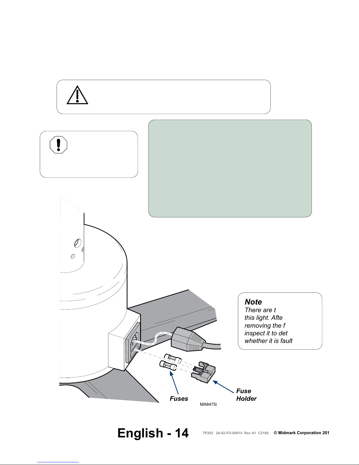
Replacing the Fuses - continued
Mobile Lights
MA8475i
To replace fuses...
A) Turn light OFF ( ).
B) Disconnect power from light.
C) Using a flat-bladed screwdriver, push in on
locking tab, then pull fuse drawer out.
D) Pull fuses out of fuse drawer to inspect.
E) Insert fuses into fuse drawer.
F) Insert fuse drawer into AC inlet.
(Push in until you hear a clicking sound).
G) Connect power and verify operation.
O
I
Caution
To completely isolate the light from electrical mains supply,
power cord must be unplugged.
Note
There are two fuses on
this light. After
removing the fuse,
inspect it to determine
whether it is faulty.
Equipment
Alert
Do not block the
electrical outlet where light
connects into.
Fuses
Fuse
Holder
© Midmark Corporation 2016
003-2848-99
TP202 20-42-FO-00014 Rev A1 C2169
English - 15
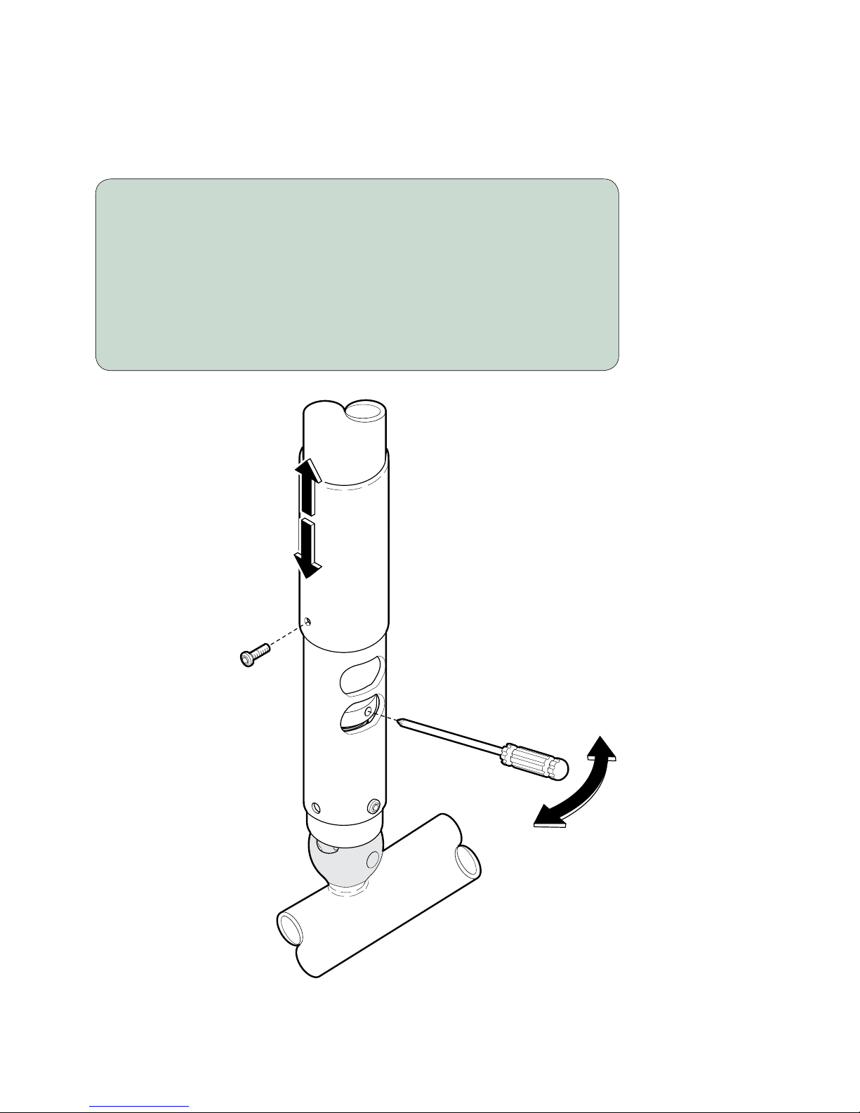
Ball Pivot Tension Adjustment
To adjust ball pivot tension...
A) Remove screw, then slide sleeve up to expose opening.
B) Insert screwdriver into adjustment hole.
C) Move the screwdriver LEFT / RIGHT to adjust tension setting
(LEFT: decreases tension / RIGHT: increases tension)
D) Remove screwdriver, and check for desired tension.
Repeat Step C until desired tension is achieved.
E) Slide sleeve down, then install screw.
MA8355i
CRAFTSM
AN
Increase
Decrease
Ceiling / Wall model shown.
Mobile model is similar
© Midmark Corporation 2016
003-2848-99
TP202 20-42-FO-00014 Rev A1 C2169
English - 16
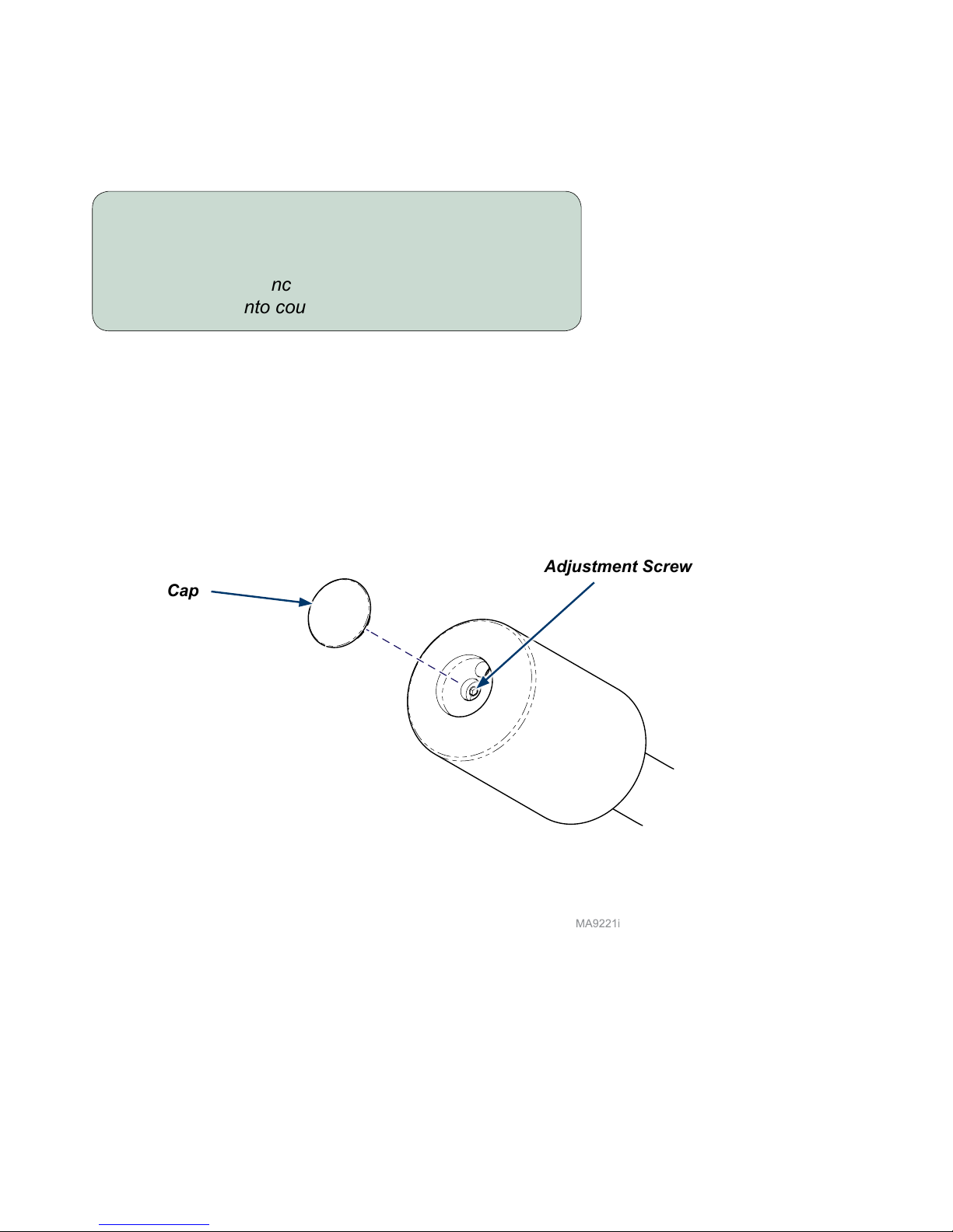
Cross Tube Counterbalance Adjustment
To adjust cross tube counterbalance...
A) Remove cap from counterbalance.
B) Loosen / tighten the adjustment screw until the
cross tube balances in horizontal position.
C) Install cap onto counterbalance.
Cap
Adjustment Screw
© Midmark Corporation 2016
003-2848-99
TP202 20-42-FO-00014 Rev A1 C2169
English - 17
Specications
Specications
Illumination @ 1 m (39 in): 7500 fc (80,729 lux)
Dim Setting Central Illuminance
Setting 1 (highest) 7500 fc (80,729 lux)
Setting 2 6200 fc (66,736 lux)
Setting 3 4400 fc (47,361 lux)
Setting 4 (lowest) 3400 fc (36,597 lux)
LED Light Life: >30,000 hours @ Ec≥70
Color Temperature: 4,400K (±300)
Color Rendering Index (CRI): 98
Total Irradiance: 300 w/m
2
Lighthead Field Diameter: 7.5 in. (19 cm)
D50 / D10 ratio: 0.5
Electrical Requirements:
115 VAC models 115 VAC, 50/60 Hz, 0.7 A, single phase
230 VAC models 230 VAC, 50/60 Hz, 0.5 A, single phase
Fuse Rating:
115 VAC models 1.6A, 250 VAC, 5mm x 20mm,
Type T, Slo-Blo, Time Lag, High Breaking Capacity
(HBC)
230 VAC models 1.6A, 250 VAC, 5mm x 20mm,
Type T, Slo-Blo, Time Lag, High Breaking Capacity
(HBC)
Range of Motion / Height: Refer to Dimension / Range of Motion section
Power Cord (Mobile Models only): 120 in. (3 m) long, Hospital Grade grounding plug

© Midmark Corporation 2016
003-2848-99
TP202 20-42-FO-00014 Rev A1 C2169
English - 18
Specications - continued
Specications - continued
Classications: FDA Class 1, Type B, continuous operation (refer to
Model Identication / Compliance Chart)
Certications:
All Models Listed by TUV
Weight:
Mobile Models 65.8 lbs (29.8 kg)
Wall Mounted Model 85 lbs (38.6 kg)
Ceiling Mounted Models:
single light (8 ft. ceiling) 64 lbs (29.1 kg)
single light (9 ft. ceiling) 65 lbs (29.5 kg)
double light (8 ft. ceiling) 116 lbs (52.7 kg)
double light (9 ft. ceiling) 118 lbs (53.6 kg)
© Midmark Corporation 2016
003-2848-99
TP202 20-42-FO-00014 Rev A1 C2169
English - 19
WARNING
Equipment is not suitable for use in the presence of a flammable anesthetic
mixture.
Clarification: Equipment is suitable for use in the presence of oxygen, air, or nitrous oxide.
WARNING
Do not modify this equipment without authorization of the manufacturer.
Caution
To completely isolate the light from electrical mains supply:
For lights provided with a power cord, the power cord must be unplugged.
For lights wired directly to mains supply, the wiring must be connected to an appropriately sized
circuit breaker and the circuit breaker must be turned off.
WARNING
No modification of this equipment is allowed.
WARNING
Use of this equipment adjacent to or stacked with other equipment should be avoided
because it could result in improper operation. If such use is necessary, this equipment
and the other equipment should be observed to verify that they are operating normally.
WARNING
Use of accessories, transducers and cables other than those specified or provided
by the manufacturer of this equipment could result in increased electromagnetic
emmisions or decreased electromagnetic immunity of this equipment and result in improper
operation.
WARNING
Portable RF communications equipment (including peripherals such as antenna cables
and external antennas) should be used no closer than 12 inches (30 cm) to any part of
the Procedure Light, including cables specified by the manufacturer. Otherwise, degradation of
the performance of this equipment could result.
Warnings
© Midmark Corporation 2016
003-2848-99
TP202 20-42-FO-00014 Rev A1 C2169
English - 20
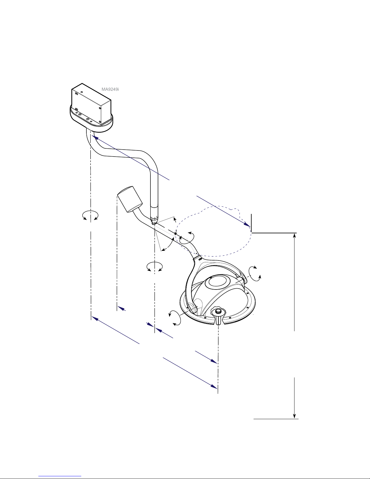
Dimensions / Range of Motion
Ceiling Lights
41
o
41
o
180
o
22.3 in
(56.7 cm)
180
o
46.3 in
(117.7 cm)
13.6 in
(34.6
cm)
56 in
(142.2 cm)
580
o
580
o
300
o
Height of lighthead adjustable from 53 in.
(135 cm) to 78 in. (198 cm) above oor.
Based on 8’ models with 8’ ceiling
and 9’ models with 9’ ceiling
© Midmark Corporation 2016
003-2848-99
TP202 20-42-FO-00014 Rev A1 C2169
English - 21
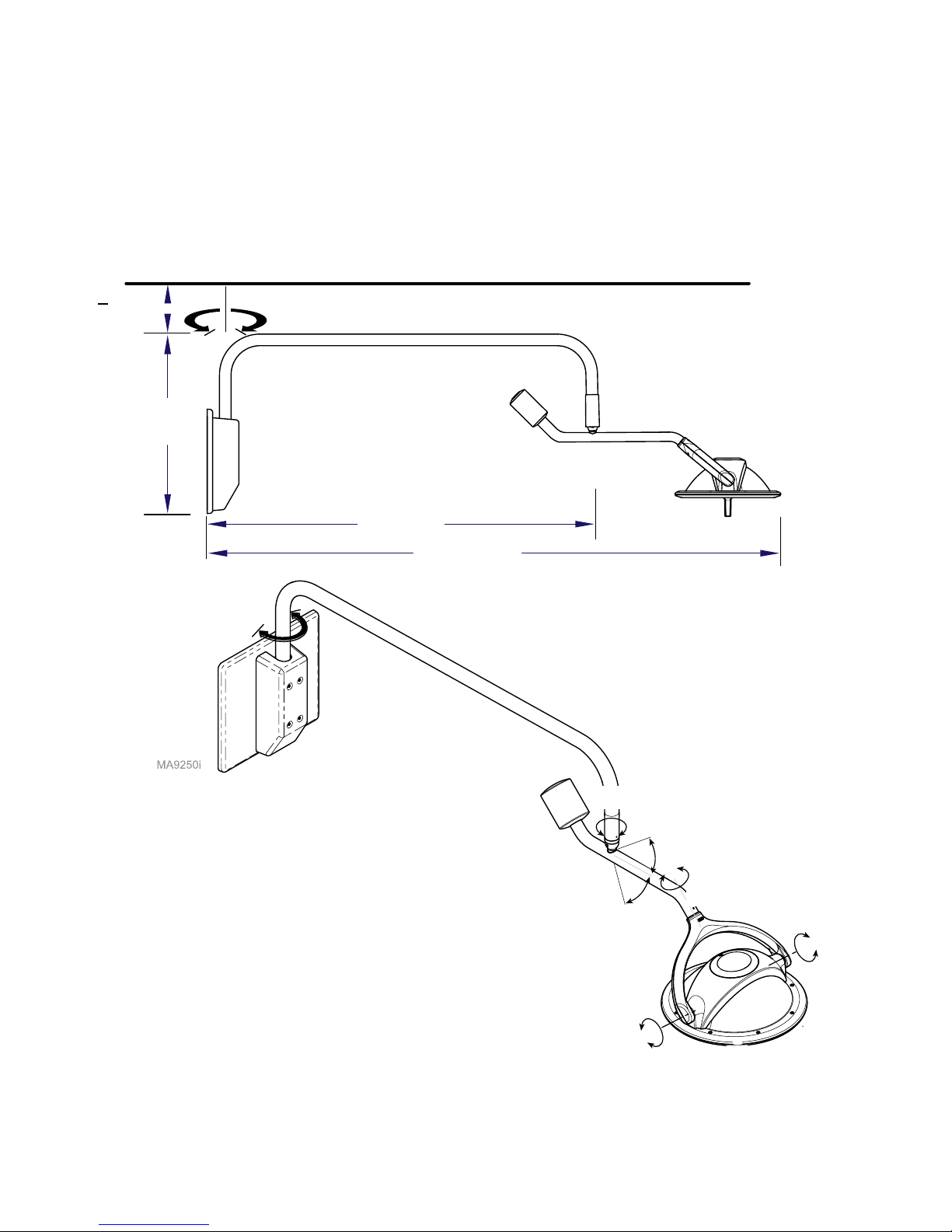
Dimensions / Range of Motion - continued
Wall Mounted Lights
63.5 in
(161.3 cm)
99 in
(251.5 cm)
31 in
(81 cm)
580
o
41
o
41
o
180
o
180
o
300
o
170
o
> 3 in.
(7.6 cm)
© Midmark Corporation 2016
003-2848-99
TP202 20-42-FO-00014 Rev A1 C2169
English - 22
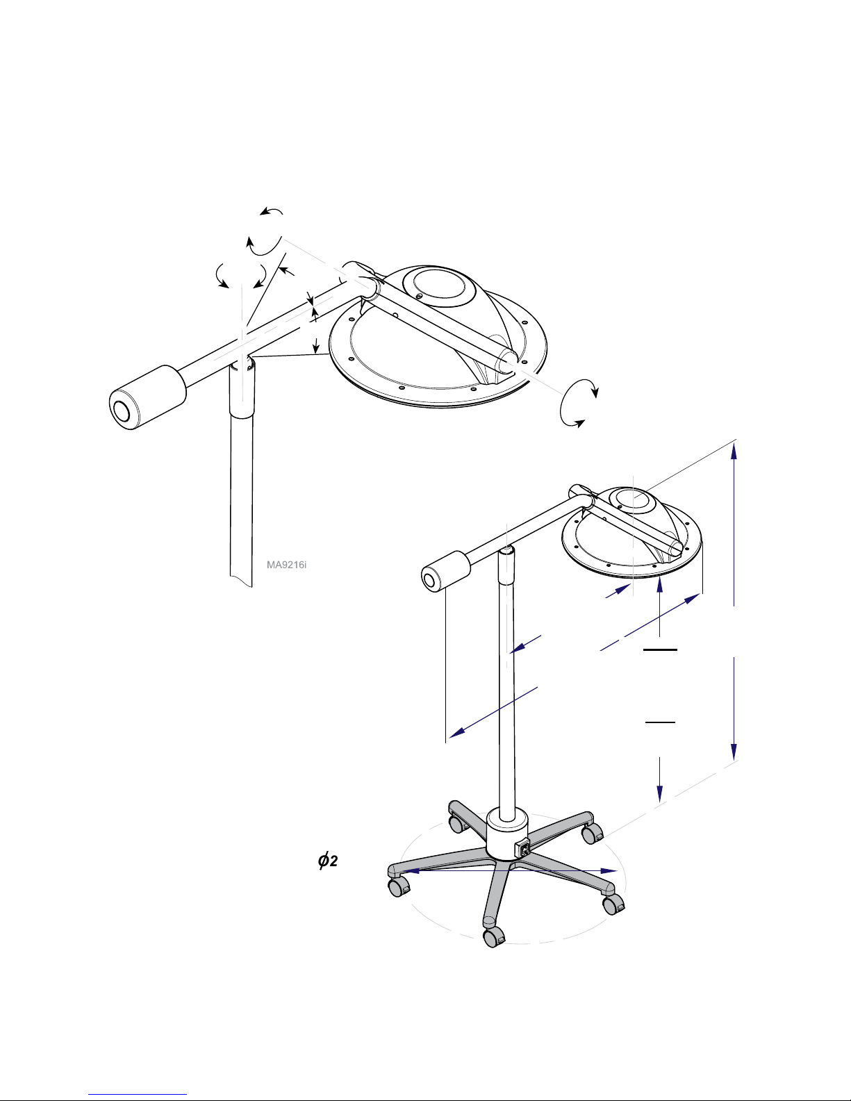
Dimensions / Range of Motion - continued
Mobile Lights
41
o
300
o
540
o
41
o
180
o
O28 in
(71.1 cm)
25.3 in
(64.3 cm)
47 in
(119.4 cm)
68 in
(172.7
cm)
Max.
88 in
(223.5 cm)
Min.
52 in
(132.1 cm)

© Midmark Corporation 2016
003-2848-99
TP202 20-42-FO-00014 Rev A1 C2169
English - 23
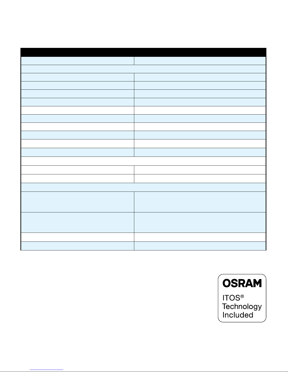
Model Identication / Compliance Chart
Model Description
Complies To: Electrical Ratings:
ES
60601-1
CAN / CSA
C22.2
#60601-1
60601-1-2
(EMC)
IEC
60601-1
60601-2-41
(Luminaires)
CE
VAC
+/-
10%
Amps
Cycles
(Hz)
255-
021
8’ single
light, ceiling,
Midmark
• • • • • •
Congurable
50 / 60115 0.7
230 0.5
255-
022
9’ single
light, ceiling,
Midmark
• • • • • •
Congurable
50 / 60115 0.7
230 0.5
255-
023
8’ double
light, ceiling,
Midmark
• • • • • •
Congurable
50 / 60115 0.7
230 0.5
255-
024
9’ double
light, ceiling,
Midmark
• • • • • •
Congurable
50 / 60115 0.7
230 0.5
255-
025
Mobile light,
Midmark
• • • • • •
Congurable
50 / 60115 0.7
230 0.5
255-
026
Wall Mount
light,
Midmark
• • • • • •
Congurable
50 / 60115 0.7
230 0.5
255-
027
Mobile Light
w/o cord,
Midmark
• • • • • •
Congurable
50 / 60115 0.7
230 0.5

© Midmark Corporation 2016
003-2848-99
TP202 20-42-FO-00014 Rev A1 C2169
English - 24
Immunity Test Immunity Test Level
Electrostatic Discharge (ESD)
IEC 61000-4-2
± 8 kV Contact, ±8 kV Air – Limited movement of patient
and practitioner during procedure minimizes need to
reposition light
Radiated RF EM Fields
IEC 61000-4-3
3V/m
80MHz-2.7 GHz 80% AM at 1kHz
Rated Power Frequency Magnetic Fields
IEC 61000-4-8
30 A/m
Electrical Fast Transients
IEC 61000-4-4
±2 kV at 100kHz repetition frequency
Surges
IEC 61000-4-5
Line to Line: ±1 kV
Line to Ground: ±2 kV
Conducted RF
IEC 61000-4-6
3V: 0.15MHz -80MHz
6V in ISM Bands between 0.15MHz - 80MHz
80% AM at 1kHz
Voltage Dips
IEC 61000-4-11
0 % UT; 0,5 cycle
At 0°, 45°, 90°, 135°, 180°, 225°, 270° and 315°
0 % UT; 1 cycle
and
70 % UT; 25/30 cycles
Single phase: at 0°
Voltage Interruptions
IEC 61000-4-11
0 % UT; 250/300 cycle
Note
The emissions characteristics of this equipment make it suitable for use in industrial areas and
hospitals. The procedure light is not intended to be used in a residential environment.
Emissions Test Emissions Test Level
Conducted and Radiated RF Emissions CISPR 11 Group 1 Class A
EMC - Manufacturer’s Declaration and Guidance

© Midmark Corporation 2016
003-2848-99
TP202 20-42-FO-00014 Rev A1 C2169
English - 25
Midmark Limited Warranty - Dental Products
SCOPE OF WARRANTY
Midmark Corporation (“ Midmark”) warrants to the original retail purchaser that it will at Midmark’s option repair
or replace components of the dental products manufactured by Midmark (except for components not warranted
under “Exclusions”) that are defective in material or workmanship under normal use and service. Midmark’s
obligation under this limited warranty is limited to the repair or replacement of the applicable components. This
limited warranty shall only apply to defects that are reported to Midmark within the applicable warranty period
and which, upon examination by Midmark, prove to be defective. This warranty extends only to the rst retail
purchaser of a product and is not transferable or assignable. Replacement components or products may be
used and/or refurbished components or products, provided they are of like quality and specications as new
components or products.
APPLICABLE WARRANTY PERIOD
The applicable warranty period, measured from the date of delivery to the original user, shall be as follows:
Eective March 1, 2018 these applicable warranty periods are measured from the date of invoice to the
original user, shall be as follows:
1. OPERATORY PRODUCTS
a. Five (5) years for all products (except for the items in (b) through (e)).
b. Two (2) years for upholstery (chairs and stools).
c. “KINK-VALVE” module carries a ten (10) year warranty.
d. The original light bulb on a new light carries a one (1) year warranty.
e. Accessories not manufactured by Midmark are excluded including but not limited to Bien Air handpiece
systems, Dentsply Cavitron scaler, Satelec scaler and curing light, and Sopro cameras.
2. ORAL SURGERY PRODUCTS are warranted for a period of one (1) year.
3. STERILIZER PRODUCTS are warranted for a period of one (1) year.
4. ULTRASONIC CLEANER PRODUCTS are warranted for a period of two (2) years.
5. AIR AND VACUUM PRODUCTS
a. PowerAir® oil-less compressors – Five (5) years or 3,500 hours of use, whichever occurs rst. b.
PowerVac® and PowerVac® G dry vacuums – Five (5) years or 10,000 hours of use, whichever
occurs rst (except that the vacuum pump warranty term is ten (10) years or 20,000 hours of use,
whichever occurs rst).
c. Classic Series® wet-ring vacuums – Five (5) years or 10,000 hours of use, whichever occurs rst.
d. PowerMax surgical suction – Two (2) years.
e. Hg5 Series Amalgam Separator - One (1) year. (f) Midmark manufactured accessories - One (1) year.
6. SYNTHESIS™ DENTAL CASEWORK AND ARTIZAN® EXPRESSIONS PRODUCT
a. Five (5) years for all products and components including door and drawer fronts, casters and
slides, except for the items in (b), (c) and (d).
b. Three (3) years for electrical components such as task lights/LED lights, cords, controls and
accessories.
c. Two (2) years for sliding track monitor mount and components and upholstery. (d) One (1) year for
countertops and resin, including accessories.

© Midmark Corporation 2016
003-2848-99
TP202 20-42-FO-00014 Rev A1 C2169
English - 26
7. IMAGING PRODUCTS are warranted for a period of two (2) years except for the ClearVision CR reader
which is warranted for a period of one (1) year.
8. MIDMARK Replacement Parts and Accessories carry a ninety (90) day warranty
EXCLUSIONS
This warranty does not cover and Midmark shall not be liable for the following;
1. defects, damage or other conditions caused, in whole or in part, by misuse, abuse, negligence,
alteration, accident, freight damage, negligent storage, tampering or failure to seek and obtain repair
or replacement in a timely manner;
2. products which are not installed, used, and properly cleaned and maintained as required or
recommended in the Midmark “Installation” and/or “Installation/Operation Manual” for the applicable
product, including the specied structural and operational environment conditions and electrical
power requirements;
3. products considered to be of a consumable or sterile nature;
4. accessories or parts not manufactured by Midmark;
5. charges by anyone for adjustments, repairs, replacement parts, installation or other work performed
upon or in connection with such products which are not expressly authorized in writing in advance
by Midmark
6. costs and expenses of routine maintenance and cleaning;
7. representations and warranties made by any person or entity other than Midmark;
8. matching of color, grain or texture except to commercially acceptable standards;
9. changes in color caused by natural or articial light;
10. custom manufactured products;
11. alterations or modications to the product by any person or entity other than Midmark; and
12. Products that would otherwise by covered under Sections 1 and 2 of this limited warranty, but are
acquired: (i) from a person or entity that is not Midmark or one of its authorized dealers; or (ii) from a
Midmark dealer that is not authorized to sell the product at issue in the geographic territory where the
purchaser is located, or is not authorized to sell the product at issue within the medical, animal
health or dental market, as the case may be, in which purchaser intends to use the product.
EXCLUSIVE REMEDY; CONSEQUENTIAL DAMAGES DISCLAIMER
MIDMARK’S ONLY OBLIGATION UNDER THIS LIMITED WARRANTY IS THE REPAIR OR
REPLACEMENT OF DEFECTIVE PARTS. MIDMARK SHALL NOT BE LIABLE FOR AND HEREBY
DISCLAIMS ANY DIRECT, SPECIAL, INDIRECT, INCIDENTAL, EXEMPLARY OR CONSEQUENTIAL
DAMAGES OR DELAYS, INCLUDING, BUT NOT LIMITED TO, DAMAGES FOR LOSS OF PROFITS OR
INCOME, LOSS OF USE, DOWNTIME, COVER AND EMPLOYEE OR INDEPENDENT CONTRACTOR
WAGES, PAYMENTS AND BENEFITS.
WARRANTY DISCLAIMER
THIS LIMITED WARRANTY IS MIDMARK’S ONLY WARRANTY AND IS IN LIEU OF ALL OTHER
WARRANTIES, EXPRESS OR IMPLIED.MIDMARK MAKES NO IMPLIED WARRANTIES OF ANY KIND
INCLUDING ANY IMPLIED WARRANTIES OF MERCHANTABILITY OR FITNESS FOR A PARTICULAR
PURPOSE. THIS WARRANTY IS LIMITED TO THE REPAIR OR REPLACEMENT OF DEFECTIVE PARTS.
STATUE OF LIMITATIONS
No action my be brought against Midmark for breach of this limited warranty, or implied warranty, if any, or
for any other claim arising out of or relating to the products, more than ninety (90) days following expiration
of the limited warranty period.
 Loading...