

Page 1
Universal
Style B
Procedures Chair
Model Numbers:
230
630
75
-001 thru -004
-001 thru -009
-019 thru -021
Service and
Parts Manual
Some Models NO LONGER IN PRODUCTION
Some service parts may not be available for this product!
FOR USE BY MIDMARK TRAINED TECHNICIANS ONLY
SF-1838 Part No. 004-0409-00 Rev. AA6 (3/11/19)
630 shown
Page 2

GENERAL INFORMATION
Back
Symbols ....................................iii
Ordering Parts .......................... iii
Model / Serial Number
Location .................................. iii
Weights, Dimensions,
Electrical Specifications ....... iv
Model Identification /
Compliance Charts:
230 & 75 (-019) .........................
630 & 75 (-020 / -021) ...............
General Information
Scheduled Maintenance .......... vii
OPERATION &
TROUBLESHOOTING
Error Codes
Power To The Chair:
Models w/ Standard Base .............
Models w/ Rotational Base ...........
Base Up / Down ........................ A-8
Section A
Back Up / Down ........................ A-18
Tilt Up / Down ........................... A-28
Foot Up / Down......................... A-38
Crash Avoidance System ........A-48
Position Programming ............ A-52
"Home" Function ..................... A-56
Quick Chair™
Chair Receptacles .................... A-66
Upholstery Heater System ...... A-68
Rotational Base
Brake System ......................... A-72
(Refer to page B-40)
Function........... A-62
v
vi
A-2
A-4
COMPONENT
TESTING & REPAIR
Isolation Transformer /
Chair Receptacles.................. B-29
Main System Transformer ....... B-30
Position Sensors...................... B-32
Section B
Main PC Board
Upholstery Heater System ......B-45
Headrest Mechanism ............... B-50
Rotational Base
Brake System ......................... B-51
- continued
(Error Codes) .......
ACCESS PROCEDURES
Removing & Installing:
PC Board Cover:
Models w/ Standard Base ........
Models w/ Rotational Base ......
Base Shrouds:
Raising (w/bungee cord) ..........
Section C
Removing / Installing................
Upholstery ........................... C-6
Back Section Covers .......... C-7
Seat Section Covers ........... C-8
Foot Section Covers:
Midmark Models ......................
Ritter Models .........................
Junction Board Cover....... C-11
WIRING DIAGRAMS
230 ..........................................D-1
630 ..........................................D-1
75 ........................................... D-1
B-40
C-2
C-3
C-4
C-5
C-9
C-10
COMPONENT
Section D
TESTING & REPAIR
Primary Fuses .......................... B-2
Limit Switches .......................... B-3
Hand / Foot Controls ............... B-6
Table Of Contents
Base Actuator........................... B-11
Back Actuator........................... B-17
Section B
Tilt Actuator .............................. B-21
Foot Actuator ........................... B-25
Gas Springs .............................. B-28
FOR USE BY MIDMARK TRAINED TECHNICIANS ONLY
Section E
EXPLODED VIEWS / PARTS LISTS
230 .........................................E-2
630 .........................................E-3
75:
Section E
*
Indicates multiple pages due to a serial number break for the parts illustration
(-019) .......................................
(-020 / -021) .............................
E-2
E-3
Rev. 10/5/18
Page 3
Symbols
Go To Table Of Contents
Next
Back
General Information
Ordering Parts
WARNING
Indicates a potentially hazardous situation which
could result in serious injury if not avoided.
Caution
Indicates a potentially hazardous situation
which could result in injury if not avoided.
Equipment Alert
Indicates a potentially hazardous situation which
could result in equipment damage if not avoided.
Note
Amplifies a procedure, practice, or condition.
In Section A, test the components in the order indicated.
(ex.
1st
then,
These symbols are used throughout this manual to represent the
operational status of chair functions and components.
Refer to Section B for component testing procedures.
2nd
)
The following information is required when ordering parts:
• Serial number & model number
• Part number for desired part.
[Refer to Exploded Views / Parts Lists section]
Non-warranty parts orders may be faxed to Midmark using
the Fax Order Form in the back of this manual.
For warranty parts orders, call Midmark's Technical Service
Department with the required information.
Hours: 8:00 am until 5:00 pm EST [Monday - Friday]
Phone: 1-(800)-Midmark
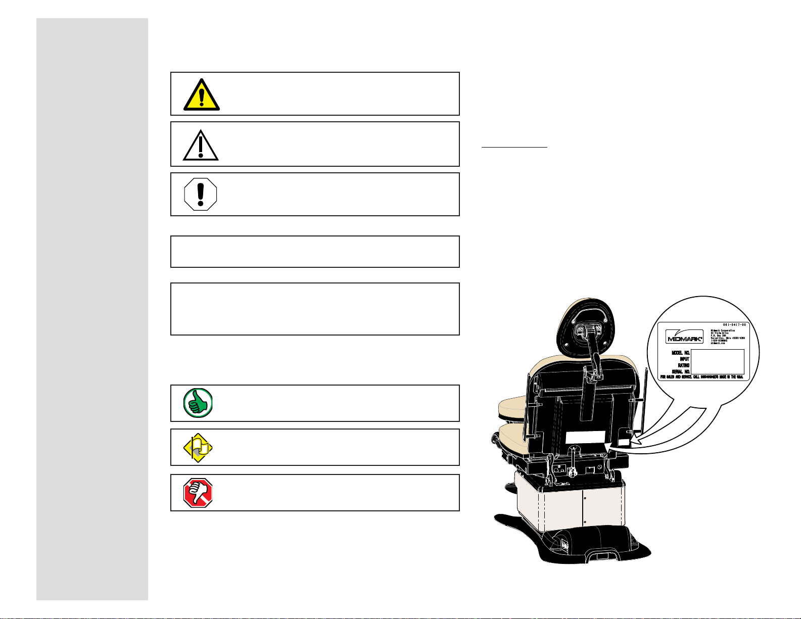
Model / Serial Number Location
Indicates the function / component is working properly.
No action required.
Indicates the function / component is working,
but a problem exists.
Indicates the function / component is not working at all.
General Information
Model 630-000 thru -009 is shown.
Location is the same for
230 & 75 models.
© Midmark Corporation 2005 SF-1838
MA643201i
iii
Rev. (10/5/18)
Page 4
General Information
MA643601i
i
Go To Table Of Contents
Next
Back
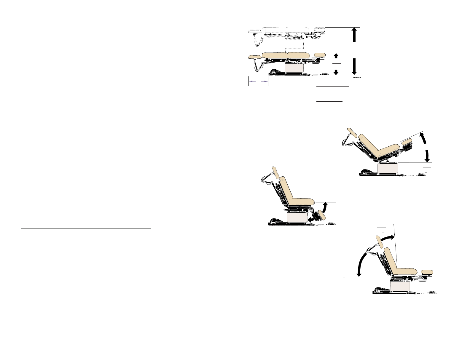
Weights, Dimensions, Electrical Specifications
Patient Weight (Maximum) .................................450 lbs (204.1 kgs)
Paper Roll (maximum size): ..............................18 in. long x 3.5 in. diameter
(45.7 x 8.9 cm)
Range of Motion &
Dimensions .......................................................[See illustration]
Weight of Chair:
230 / 630 / 75 (w/standard base) ....................... 455 lbs (206.4 kg)
w/packaging & skid ........................................... 510 lbs (231.3 kg)
230 / 630 / 75 (w/rotational base) ......................540 lbs (244.9 kg)
w/packaging & skid ........................................... 600 lbs (271.1 kg)
Power Cord: ........................................................ 8 ft. (243.8 cm) long
Electrical Requirements: ................................... [See Compliance Charts]
19 in.
(48.2 cm)
Min.
* see below
* Midmark models
w/ standard base:
w/rotational base:
Ritter models
w/standard base:
w/rotational base:
Max.
Standard base:
Rotational base:
19 in. (48.2 cm)
22.5 in. (57.1 cm)
22.5 in. (57 cm)
26 in. (66 cm)
40 in. (101.6 cm)
43.5 in. (110.5 cm)
Max.
30° +2°
Foot / Hand Control Voltage: .............................10 VAC, SELV (Safety Extra Low Voltage)
Duplex Receptacle (optional)
maximum load: ................................................. 115 VAC, 3A, 50/60 Hz
Fuses:
Main Power
(located at power cord inlet)
:
F1 & F2 .................................................................6.3A, 250V, Type-T, 5 x 20 mm
High-Breaking Current
Upholstery Heater
(located on uph. heater PC board)
:
F1 & F2 .................................................................1/2 A, 250V, Type-T, 1-1/4" x 1/4"
Duty Cycle
(motor run time)
: ............................... Intermittent Operation
[30 seconds ON / 5 minutes off]
Classifications: ...................................................Class 1, Type B Applied Part
Protection against ingress of fluids: ............... Ordinary Equipment
Foot Control only: ................................................
IPX1
Regulatory Compliance: ....................................[See Compliance Charts]
Chair Speeds (by function):
Base / Back / Tilt
Foot
(630) .............................................................
Foot
(230) .............................................................
(all models) ..............................
15 - 25 seconds
less than 15 seconds
less than 20 seconds
Min.
89° +1°
Max.
0° +0.5°
MA643801
0° +0.5°
Min.
0° +0.5°
MA643701i
Max.
85° +3°
Min.
iv
© Midmark Corporation 2005 SF-1838
Equipment not suitable for use in the presence of a flammable anesthetic mixture with air, or with oxygen, or nitrous oxide.
Rev. 10/5/18
Page 5

Model Identification / Compliance Chart - 230 & 75 (-019)
Go To Table Of Contents
Next
Back
Fire Code Ratings
All standard upholstery sets comply with: California Bureau of Home Furnishing Technical Bulletin 117
Optional upholstery sets are available that comply with:California Bureau of Home Furnishing Technical Bulletin 133.
General Information
Model Description
230-001
230-002
230-003
75-019
(230-004)
Ritter Universal Proc. Chair
(Non-Programmable)
Ritter Universal Proc. Chair
(Non-Programmable)
w/ Receptacle
Ritter Universal Proc. Chair
(Non-Programmable)
w/ rotational base
Ritter Universal Proc. Chair
(Non-Programmable)
Serial
Number
Prefix
V
V
V
V
Complies To: Electrical Ratings:
UL
60601-1
CAN/CSA
22.2,
#601.1-M90
IEC
60601-1
EN
60601-1-2
(EMC)
x x x x
xx xx
x x x x
x x x x
VAC
+/-10%
Configurable
115
230
Amps
3.5
Cycles
(Hz)
50 / 60
7
115 10 50 / 60
Configurable
115
230
Configurable
115
230
7.5
3.8
3.5
50 / 60
50 / 60
7
© Midmark Corporation 2005 SF-1838
Rev. (10/5/18)
v
Page 6

General Information
Go To Table Of Contents
Next
Back
Model Identification / Compliance Chart - 630 & 75 (-020 / -021)
Fire Code Ratings
All standard upholstery sets comply with: California Bureau of Home Furnishing Technical Bulletin 117
Optional upholstery sets are available that comply with:California Bureau of Home Furnishing Technical Bulletin 133.
Model Description
630-001
630-002
630-003
630-004
630-005
630-006
Midmark Universal Proc. Chair
(Non-Programmable)
Midmark Universal Proc. Chair
(Programmable)
Midmark Universal Proc. Chair
(Non-Programmable)
w/ Receptacle
Midmark Universal Proc. Chair
(Programmable)
w/ Receptacle
Midmark Universal Proc. Chair
(Non-Programmable)
w/ Rotational Base
Midmark Universal Proc. Chair
(Prog.) w/ Rotational Base
Serial
Number
Prefix
V
V
V
V
V
V
Complies To: Electrical Ratings:
UL
60601-1
CAN/CSA
22.2,
#601.1-M90
IEC
60601-1
EN
60601-1-2
(EMC)
xx xx
x x x x
xx xx
x x x x
xx xx
x x x x
VAC
+/-10%
Configurable
115
230
Configurable
115
230
Amps
3.5
3.5
Cycles
(Hz)
50 / 60
7
50 / 60
7
115 10 50 / 60
115 10 50 / 60
Configurable
115
230
Configurable
115
230
7.5
3.8
7.5
3.8
50 / 60
50 / 60
vi
© Midmark Corporation 2005 SF-1838
630-007
75-020
(630-008)
75-021
(630-009)
Midmark Universal Proc. Chair
(Programmable)
w/ Heated Upholstery
Midmark Universal Proc. Chair
(Non-Programmable)
w/ Receptacle
Midmark Universal Proc. Chair
(Programmable)
w/ Receptacle , no foot control
Rev. (10/5/18)
V
V
V
xx xx
x x x x
xx xx
115 7 50 / 60
115 10 50 / 60
115 10 50 / 60
Page 7

General Information
Interval
Inspection or
Service
Service, Adjust , Repair
and / or Replace as Required
(Refer to appropriate S&P or Quick Reference Guide)
230 630
Clean upholstery with diluted bleach solution 10:1
(water:bleach)
XX
Wipe painted metal & plastic surfaces with a clean soft cloth
and mild cleaner.
XX
Obvious Damage
Visually inspect components for damage that could cause
problems during operation or unsafe operation.
XX
Check all mechanical functions using the foot control. Repeat
using the hand control when present.
XX
Chair shrouds should move smoothly & quietly when base is
raised & lowered. (NOTE: There are plastic glides on the
shroud tabs. Missing glides may result in noisy operation.)
XX
Labels / Decals Replace any missing or illegible labels.
XX
Hardware All fasteners must be present and fastened securely.
XX
Inspect power cord and all wiring for damage.
XX
Be sure all electrical connections are tight.
XX
Date of Service: _____/____/____
Location:
Service
Technician:
Model:
Serial Number:
Scheduled Maintenance
Universal Procedures Chair
Weekly
Cleaning
Semi-Annually
Electrical System
Mechanical
Operation
Go To Table Of Contents
Next
Back
© Midmark Corporation 2005 SF-1838
Rev. (10/5/18)
vii
Page 8

General Information
Back
Go To Table Of Contents
viii
© Midmark Corporation 2005 SF-1838
Page 9

Operation & Troubleshooting
Back
Go To Table Of Contents
Next
Go To Page:
Click on the Go To Page button and
enter the desired page number. (Note:
Letters are case sensitve. ex. A-2)
Operation &
Troubleshooting
Function / System Page
Power To The Chair:
models w/Standard Base ..................
models w/Rotational Base .................
Base Up / Down ................................... A-8
Back Up / Down .................................... A-18
Tilt Up/Down ......................................... A-28
Foot Up/Down ...................................... A-38
Crash Avoidance System ..................... A-48
Position Programming .......................... A-52
"Home" Function ................................... A-56
Quick Chair Function ............................ A-62
Chair Receptacles ................................. A-66
Upholstery Heater System .................... A-68
Rotational Base Brake System ............. A-72
A-2
A-4
Section A
Models:
Serial Numbers:
© Midmark Corporation 2005 SF-1838
A-1
Page 10
Operation & Troubleshooting
Go To Table Of Contents
Next
Back
Go To Page:
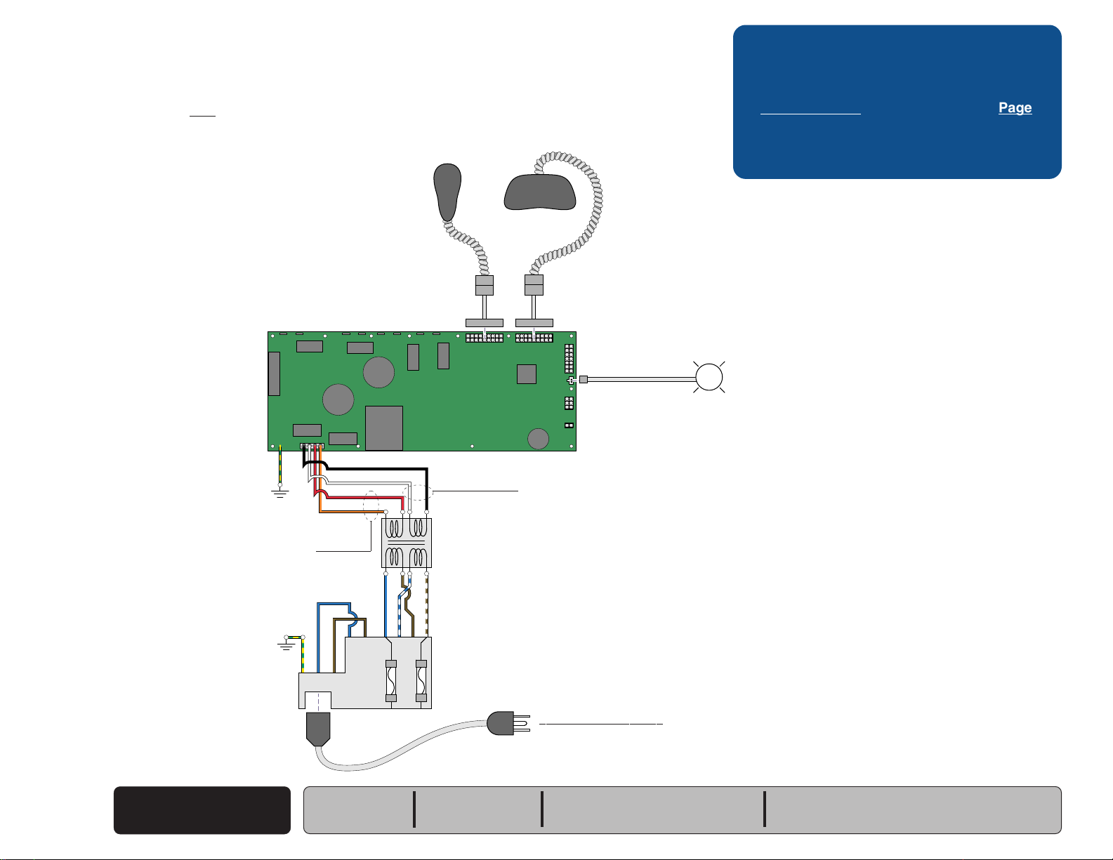
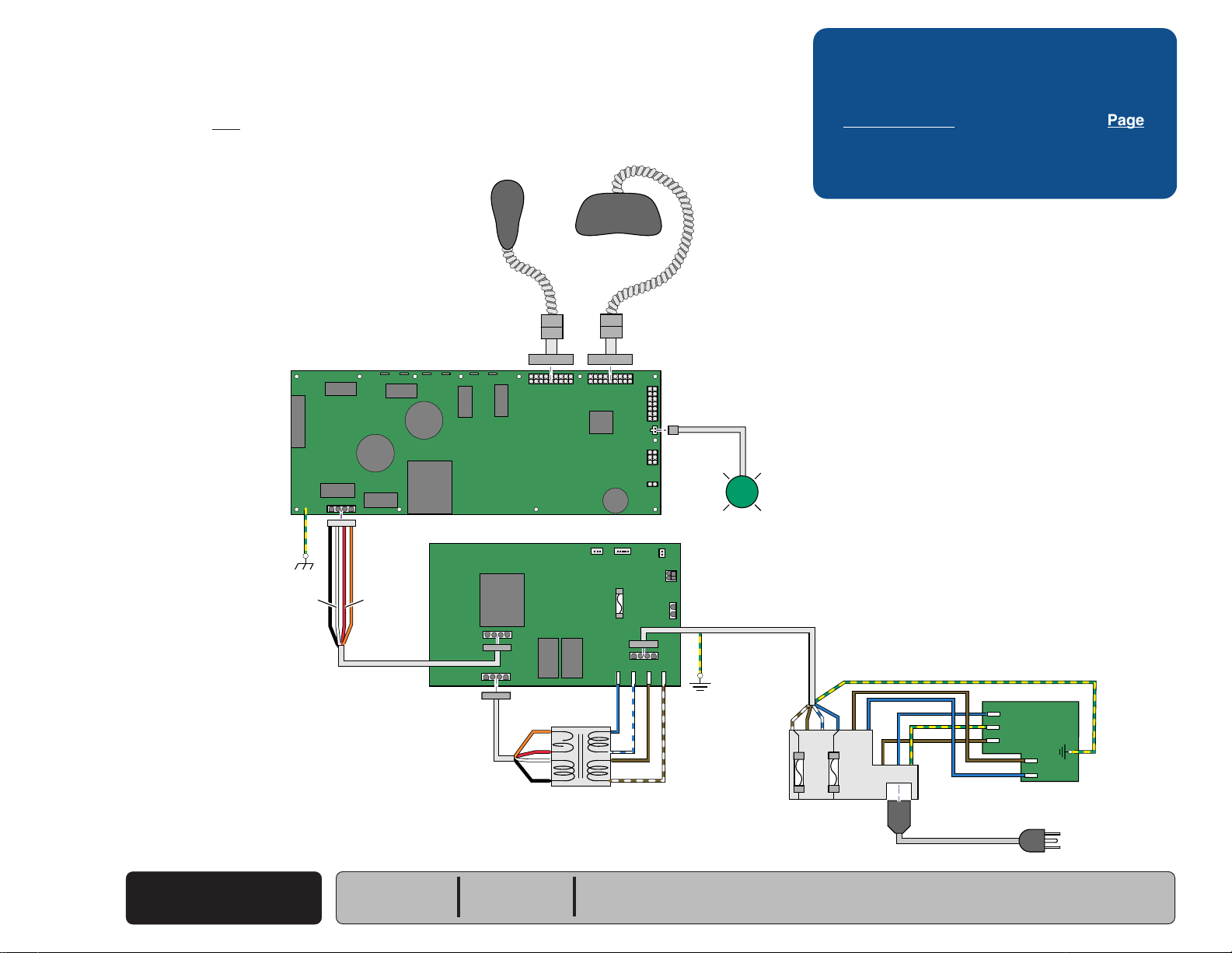
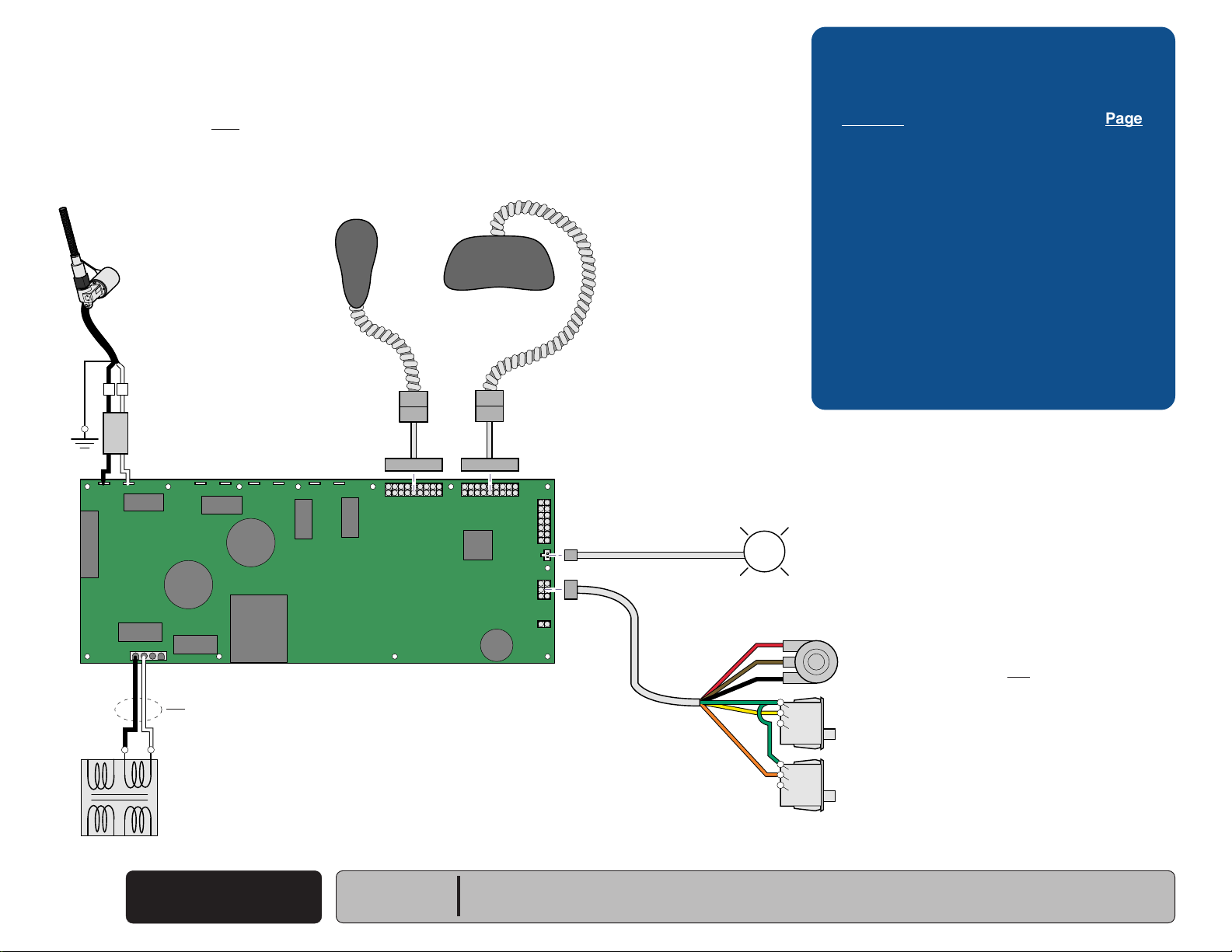
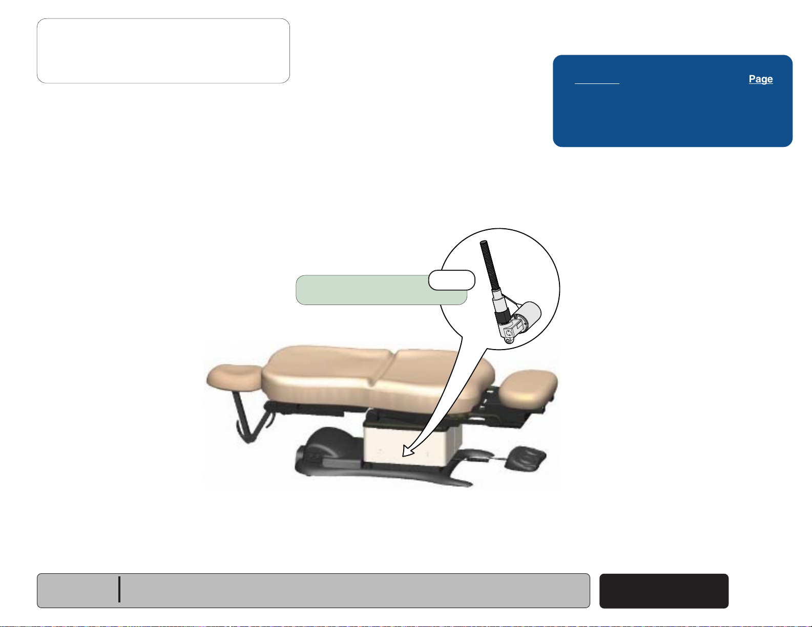
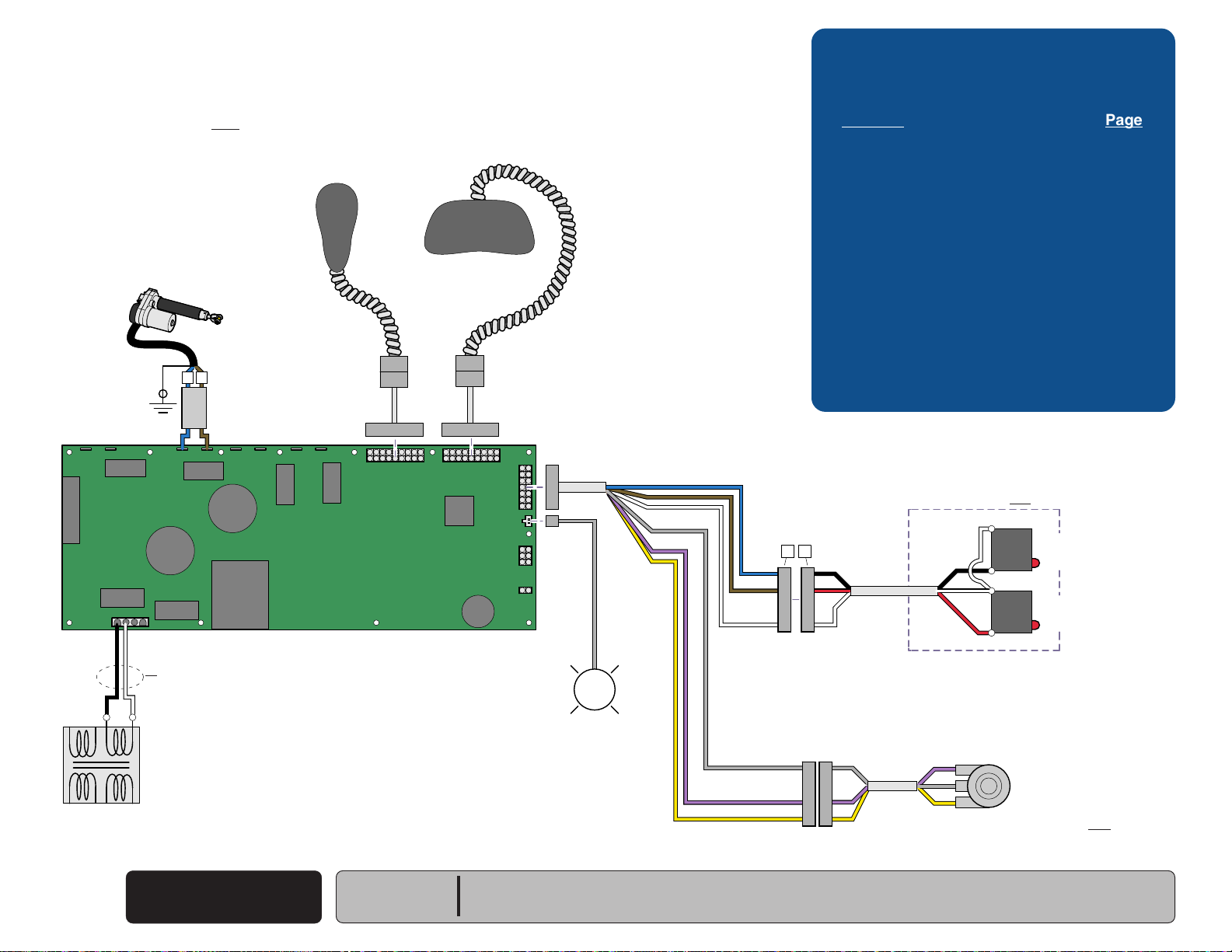
Power To The Chair
This illustration shows only the components that affect ALL CHAIR FUNCTIONS.
Refer to the following page for a detailed description of the power supply to the chair.
(models w/ Standard Base)
Hand
Control
P9 P10
Foot
Control
Troubleshooting
[No Power / No Functions Will Operate]
Power Light is: Page
OFF
..................................................... A-6
ON .......................................................
8-10 VAC8-10 VAC
A-7
J2
J1
J15
GN / YL
[Red & orange wires supply 34-37 VAC to power
circuitry for the Tilt & Foot actuators, hand/foot controls,
power light, all limit switches, and position sensors]
GN / YL
J4J3
BK
WH
RD
OR
J8J7J6J5
Main PC
Board
J10J9
MA646300i
J11
J12
J13
J14
P12
P11
L
Power
Light
[Black & white wires supply 48-54 VAC to
power circuitry for the Base & Back actuators]
If Power Light is OFF, there is no power to PC Board.
If Power Light is ON, proper voltage is present at PC Board.
Main System
Transformer
BL
BR
N
BL
BR
BR / WH
BL / WH
A
B
C
D
G
H
Power
F1
L
F2
Inlet
Facility Supply Voltage
Power To The Chair
A-2
© Midmark Corporation 2005 SF-1838
(Standard Base)
Rev. 10/5/18
Models:
Serial Numbers:
230
(-001/-002/-004)
all
630
(-001 thru -004) & (-007 thru -009)
all
75
(-019 thru -021)
all
Page 11
Operation & Troubleshooting
115V
MA646200i
230V
115V
Go To Table Of Contents
Next
Back
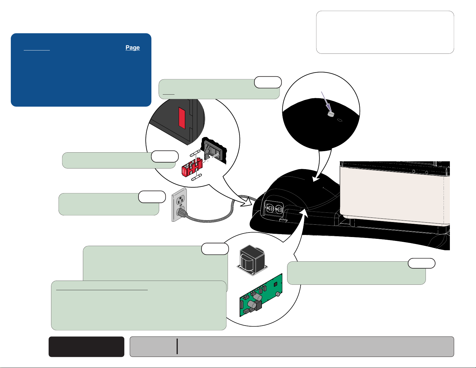
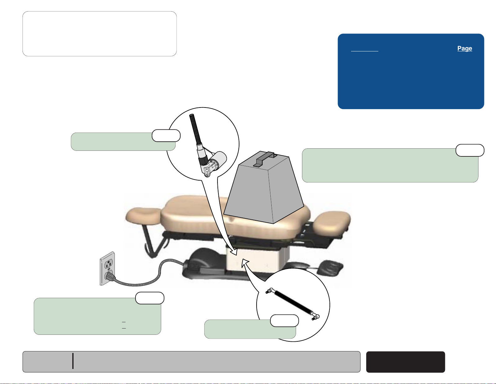
Power To The Chair
Facility Supply Voltage
With the chair's power cord properly connected, facility supply
voltage
inlet.
Power Inlet
(115 or 230 VAC)
(models w/ Standard Base)
is supplied thru the cord to the power
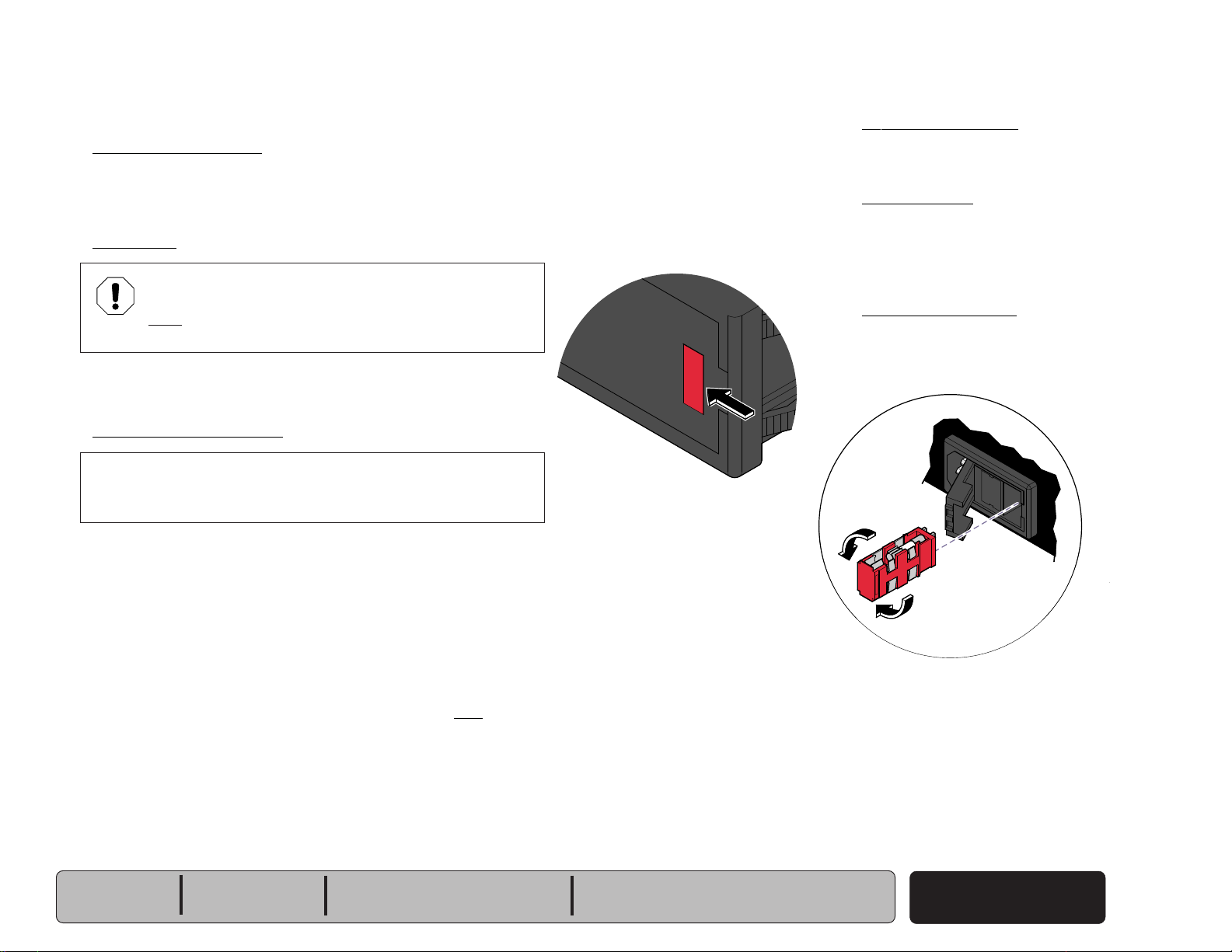
EQUIPMENT ALERT
The voltage setting displayed in the power inlet window
must match facility supply voltage
(115 or 230 VAC)
.
[Remove fuse holder and rotate 180° to change voltage setting].
Current flows thru two fuses in the power inlet, to the main system
transformer.
Main System Transformer
NOTE
This transformer is protected from overload by a thermal cutout
feature. This will automatically reset when the transformer cools.
Line voltage
transformer. The transformer reduces the voltage and current
flows to the main PC board thru two separate windings
(115 or 230 VAC)
is supplied to the main system
(four wires)
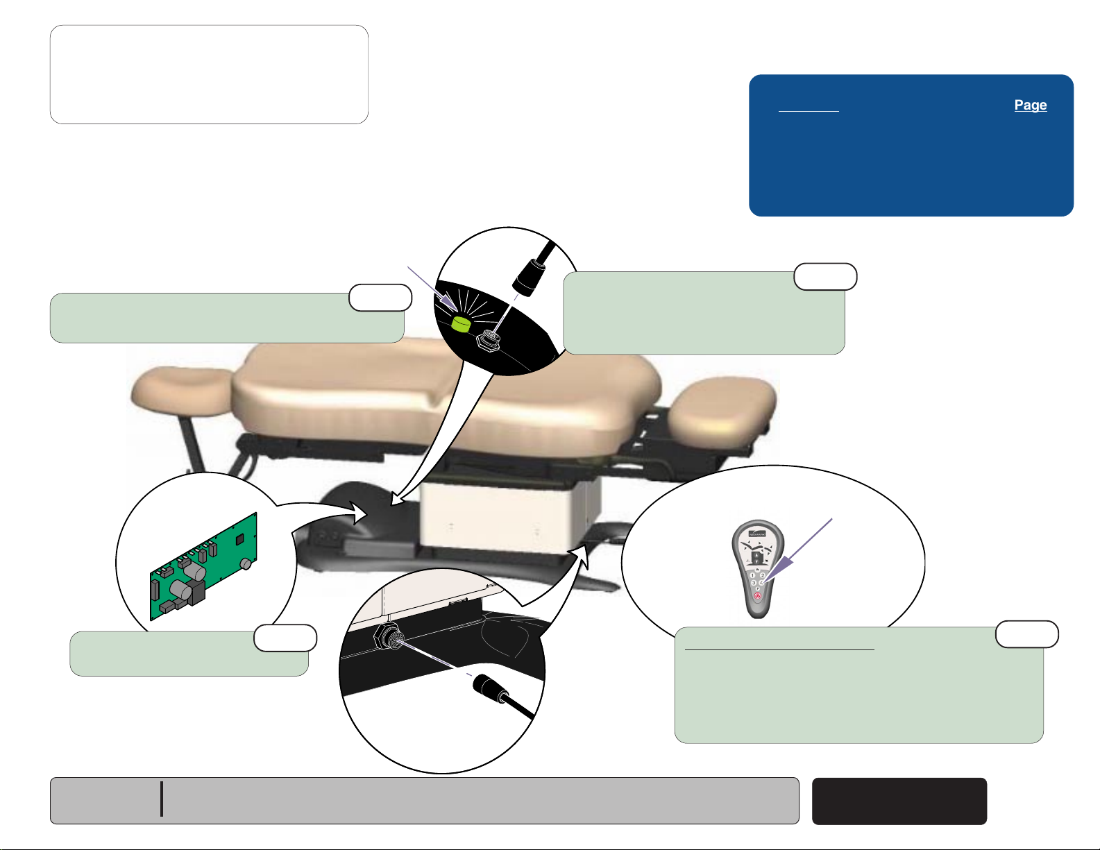
Power Indicator Light
When voltage is applied to the PC board, the
power light is illuminated.
Main PC Board
Circuitry on the PC board provides the required
voltage to power all of the chair's components:
hand/foot controls, actuators, limit switches, and
position sensors.
Hand / Foot Controls
Circuitry on the main PC board supplies 8-10
VAC to the hand / foot control connection ports.
.
[The black & white wires supply 48-54 VAC to power circuitry for
the Base & Back actuators only].
[The red & orange wires supply 34-37 VAC to power circuitry for
the Tilt & Foot actuators, hand/foot controls, power light, all limit
switches, and position sensors (on Midmark models only)].
Models:
Serial Numbers:
230
(-001/-002/-004)
all
630
(-001 thru -004) & (-007 thru -009)
all
75
(-019 thru -021)
all
Power To The Chair
(Standard Base)
© Midmark Corporation 2005 SF-1838
Rev. 10/5/18
A-3
Page 12
Operation & Troubleshooting
Go To Table Of Contents
Next
Back
Go To Page:
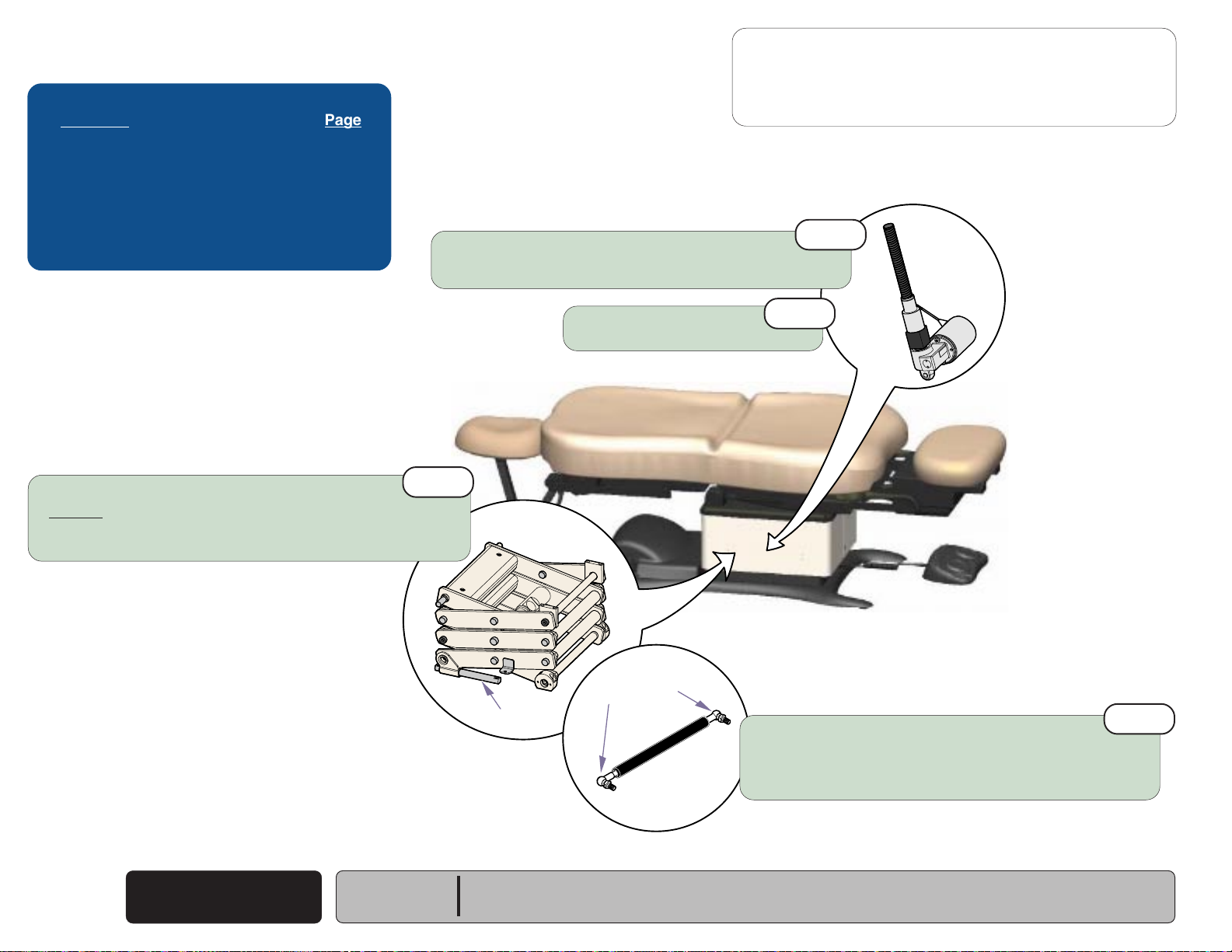
Power To The Chair
This illustration shows only the components that affect ALL CHAIR FUNCTIONS.
Refer to the following page for a detailed description of the power supply to the chair.
(models w/ Rotational Base)
Hand
Control
Foot
Control
Troubleshooting
[No Power / No Functions Will Operate]
Power Light is: Page
OFF
..................................................... A-6
ON .......................................................
A-7
[Black & white wires supply 48-54 VAC to
power circuitry for the Base & Back actuators]
[Red & orange wires supply 34-37 VAC
to power circuitry for the Tilt & Foot actuators,
hand/foot controls, power light, all limit switches,
and position sensors]
J1
J15
GN / YL
WH
BK
8-10 VAC
P9 P10
J2
J4J3
J8J7J6J5
J10J9
Main PC
Board
8-10 VAC
J11
J12
J13
J14
P12
If Power Light is OFF, there is no power to PC Board.
If Power Light is ON, proper voltage is present at PC Board.
Power
Light
OR
RD
Rotational
Base
PC Board
J10
J9
OR
RD
WH
BK
Main System
Transformer
J3
J7
BL
BR
BR/WH
J6
J5
BL/WH
J12
J2
GN / YL
J4
C
A
B
Power Inlet
GN / YL
BR
D
G
GN / YL
H
BR
L
N
BL
BL
J4
EMI Filter
J6
PC Board
J5
J1
J2
J3
Facility Supply Voltage
MA709900i
Power To The Chair
A-4
© Midmark Corporation 2005 SF-1838
(Rotational Base)
Rev. 10/5/18
Models:
Serial Numbers:
230
(-003)
all
630
(-005 & -006)
all
Page 13

Operation & Troubleshooting
115V
Go To Table Of Contents
Next
Back
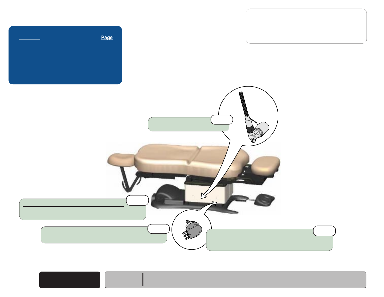
Power To The Chair
Facility Supply Voltage
With the chair's power cord properly connected, facility supply
voltage
inlet.
Power Inlet / EMI Filter Board
(115 or 230 VAC)
(models w/ Rotational Base)
is supplied thru the cord to the power
EQUIPMENT ALERT
The voltage setting displayed in the power inlet window
must match facility supply voltage
(115 or 230 VAC)
.
[Remove fuse holder and rotate 180° to change voltage setting].
Current flows from the power inlet thru the EMI filter board,
then back thru the power inlet fuses to the rotational base
PC board.
115V
230V
MA646200i
Rotational Base PC Board
Current flows thru the rotational base PC board to the main system
transformer. The transformer reduces the voltage and current flows
back to the rotational base PC board.
Circuitry on the rotational base PC board provides the required
voltage to power the rotational base brake system.
The reduced voltage is supplied to the main PC board thru the
rotational base PC board.
Main System Transformer
NOTE
This transformer is protected from overload by a
thermal cutout feature. This will automatically reset
when the transformer cools.
Line voltage
main system transformer thru the rotational base
PC board. The transformer reduces the voltage
and current flows back to the rotational base
PC board, then to the main PC board thru two
separate windings
[The black & white wires supply 48-54 VAC to
power circuitry for the Base & Back actuators only].
[The red & orange wires supply 34-37 VAC to
power circuitry for the Tilt & Foot actuators, hand/
foot controls, power light, all limit switches, and
position sensors (on Midmark models only)].
Power Indicator Light
When voltage is applied to the PC board, the power
light is illuminated.
Main PC Board
Circuitry on the PC board provides the required
voltage to power all of the chair's components:
hand/foot controls, actuators, limit switches, and
position sensors.
Hand / Foot Controls
Circuitry on the main PC board supplies 8-10 VAC
to the hand / foot control connection ports.
(115 or 230 VAC)
(four wires)
is supplied to the
.
Models:
Serial Numbers:
230
(-003)
all
630
(-005 & -006)
all
Power To The Chair
(Rotational Base)
© Midmark Corporation 2005 SF-1838
Rev. 10/5/18
A-5
Page 14
Operation & Troubleshooting
115V
Go To Table Of Contents
Next
Back
Go To Page:
Refer To: Page
Primary Fuses ...................................... B-2
Main System Transformer .................... B-30
Main PC Board ..................................... B-40
Wiring Diagrams ................................... D-1
Exploded Views / Part Numbers ........... E-1
Voltage setting
Must match facility supply voltage (115 / 230 V).
2nd
Power to the Chair
Problem: No functions will operate - and
Power Light: OFF
- continued
Power light is OFF.
1st
3rd
4th
Primary Fuses
Refer to: Section B - Primary Fuses
Faclity Supply Voltage
Check power cord connections.
Check facility circuit breaker.
Main System Transformer
Check all wire connections between power inlet
& main PC board. If connections are OK, test transformer.
Refer to: Section B - Main System Transformer
Models w/Rotational Base only:
If there is no power to the main system transformer...
Rotational Base PC Board / EMI Filter Board
Check all wire connections between rotational base PC board &
the transformer. If connections are OK, perform EMI Filter Board Test.
Refer to: Section B - Rotational Base Brake System
Main PC Board
If the transformer is OK, replace the main PC board.
Refer to: Section B - Main PC Board
MA645500i
5th
A-6
© Midmark Corporation 2005 SF-1838
Power To The Chair
Rev. 10/5/18
Models:
Serial Numbers:
ALL
Page 15
Power to the Chair
Go To Table Of Contents
Next
Back
Go To Page:
Problem: No functions will operate - and
Power light is ON.
Loose / Damaged Wire Connections
(between connection ports & PC board)
- continued
Power Light: ON
3rd
Operation & Troubleshooting
Refer To: Page
Hand & Foot Controls ............................ B-6
Main PC Board ..................................... B-40
Wiring Diagrams ................................... D-1
Exploded Views / Part Numbers ........... E-1
1st
Hand / Foot Controls
Check cords for damage / proper connection.
Check both connection ports on chair.
Refer to: Section B - Hand & Foot Controls
Check for error code(s)
Refer to: Section B - Main PC Board
Models:
Serial Numbers:
ALL
6th
MA645401i
Position "4" Button
Programmable Models only:
Press "4" button on hand control for
five seconds, then try functions again...
If chair functions operate, go to Section B,
Main PC Board (Control Lockout Feature)
If chair functions still will not move, go to next check.
Power To The Chair
© Midmark Corporation 2005 SF-1838
2nd
Rev. 10/5/18
A-7
Page 16
Operation & Troubleshooting
Go To Table Of Contents
Next
Back
Go To Page:
Base UP / DOWN Function
This illustration shows only the components that affect the Base UP / DOWN function.
Refer to the following page for a detailed description of Base UP / DOWN operation.
Hand
Base
BK
BK
Actuator
WH
WH
Control
Foot
Control
Troubleshooting
[Base Up / Down Function]
Problem Page
No Base UP or DOWN
No Base UP (DOWN - OK)
No Base DOWN (UP - OK)
All other chair functions - OK
No Base Down / Back Down / Tilt Up .............
Base Drifts Down .................................
Noisy Operation ...................................
Moves Slowly / Will Not Lift Patient ......
Up and/or Down Function
Moves Briefly, Then Stops ...............
Headrest Collides w/Floor....................
........................ A-10
.................. A-11
.......................... A-12
A-48
A-13
A-14
A-15
A-16
A-48
Choke
WH
BK
J2
J1
J15
BK
WH
A-8
© Midmark Corporation 2005 SF-1838
P9 P10
J4J3
J8J7J6J5
Main PC
Board
[Black & white wires supply 48-54 VAC to
power circuitry for the Base & Back actuators]
Main System
Transformer
Base Up / Down
Note: On models w/ rotational base, the Main System
Transformer connections are supplied thru the
Rotational Base PC Board (not shown).
Models:
Serial Numbers:
Rev. 10/5/18
J10J9
J11
J12
J13
J14
MA646400i
ALL
P12
P13
Only the wires that affect the Base Function are shown.
If Power Light is ON, proper voltage is present at PC Board.
L
If Power Light is OFF, refer to Page A-2 for troubleshooting.
Power
Light
RD
OR
YL
BN
BK
GN
GN
1
2
3
COM
NC
NO
COM
NC
NO
Base
Sensor
(Midmark models only)
Base Up
Limit Switch
Base Down
Limit Switch
Page 17

Operation & Troubleshooting
Go To Table Of Contents
Next
Back
Base UP / DOWN Function
Is There Power To The Chair?
When voltage is present at the PC board, the
power light is illuminated.
[Refer to 'Power To The Chair' (page A-2), for
description of current flow to the PC board].
Power To Foot / Hand Controls
Circuitry on the PC board supplies 8-10 VAC
to the hand / foot control connection ports.
Base Up Operation
When the Base Up function is activated,
current flows thru the hand / foot control,
back to the PC board. Circuitry on the PC Board
supplies approximately 48 VDC to the base
actuator motor.
The actuator motor runs and raises the chair.
NOTE
The PC board continuously monitors the Base
Up limit switch and the Base position sensor*.
If the Base Up limit switch is tripped (open),
the Base Up function will not operate.
If the Base position sensor* detects that the
chair has reached its upper limit, the Base Up
function will not operate.
Actuator Motor runs until:
1. Hand / foot control button is released.
2. Base Up limit switch is tripped.
3. Emergency Stop button* is pressed.
4. Position Sensor* malfunction.
5. Overcurrent protection tripped.
6. Software time-out limit is reached
(approx. 25 seconds)
.
Base Down Operation
When the Base Down function is activated,
current flows thru the hand / foot control,
back to the PC board. Circuitry on the PC Board
supplies approximately 40 VDC to the base
actuator motor.
The actuator motor runs and lowers the chair.
NOTE
The PC board continuously monitors the Base
Down limit switch and the Base position sensor.
If the Base Down limit switch is tripped (open),
the Base Down function will not operate.
If the Base position sensor* detects that the chair
is in a potential "crash position", or that the base
has reached its lower limit, the Base Down
function will not operate.
Actuator Motor runs until:
1. Hand / foot control button is released.
2. Base Down limit switch is tripped.
3. Emergency Stop button* is pressed.
4. Crash Avoidance System* activated.
5. Position Sensor* malfunction.
6. Overcurrent protection tripped.
7. Software time-out limit is reached
(approx. 25 seconds)
.
Models:
Serial Numbers:
ALL
* Midmark models only.
[This feature is not available on Ritter models]
Base Up / Down
Base Up / Down
© Midmark Corporation 2005 SF-1838
Rev. 10/5/18
A-9
Page 18
Operation & Troubleshooting
Go To Table Of Contents
Next
Back
Go To Page:
Refer To: Page
Limit Switches ...................................... B-4
Hand & Foot Controls ........................... B-6
Base Actuator ....................................... B-11
Main PC Board ..................................... B-40
Wiring Diagrams ................................... D-1
Exploded Views / Part Numbers .......... E-1
Base Up / Down Function
Problem: No Base Up or Base Down
- continued
Loose / Damaged Wire Connections
(Base Actuator, Base Up/Down Limit Switches, hand/foot control ports,
black & white wires between main system transformer & PC board)
Main PC Board
Refer to: Section B - Main PC Board
4th
1st
MA646801i
Base Actuator
Refer to: Section B - Base Actuator
Hand / Foot Control
Refer to: Section B - Hand & Foot Controls
3rd
2nd
A-10
© Midmark Corporation 2005 SF-1838
Base Up / Down
Rev. 4/24/13
Models:
Serial Numbers:
ALL
Page 19
Base Up / Down Function
Go To Table Of Contents
Next
Back
Go To Page:
Problem: No Base Up.
Base Down - OK.
Loose / Damaged Wire Connections
(Hand/Foot Control & Base Up Limit Switch)
- continued
Base Up Limit Switch
Refer to: Section B - Limit Switches
1st
2nd
Operation & Troubleshooting
Refer To: Page
Limit Switches ...................................... B-3
Hand & Foot Controls ............................ B-6
Base Actuator ....................................... B-11
Main PC Board ..................................... B-40
Wiring Diagrams ................................... D-1
Exploded Views / Part Numbers ........... E-1
Base Actuator
Refer to: Section B - Base Actuator
4th
Main PC Board
Refer to: Section B - Main PC Board
Models:
Serial Numbers:
ALL
5th
MA646901i
3rd
Hand / Foot Control
Refer to: Section B - Hand & Foot Controls
Base Up / Down
© Midmark Corporation 2005 SF-1838
A-11
Page 20
Operation & Troubleshooting
Go To Table Of Contents
Next
Back
Go To Page:
Refer To: Page
Limit Switches ...................................... B-3
Hand & Foot Controls............................ B-6
Base Actuator ....................................... B-11
Main PC Board ..................................... B-40
Wiring Diagrams ................................... D-1
Exploded Views / Part Numbers ........... E-1
Base Down Limit Switch
Refer to: Section B - Limit Switches
2nd
Base Up / Down Function
Problem: No Base Down.
Base Up - OK.
[All other chair functions - OK]
- continued
Loose Wire Connections
(Hand/Foot Control & Base Down Limit Switch)
Main PC Board
Refer to: Section B - Main PC Board
5th
1st
MA647001i
Base Actuator
Refer to: Section B - Base Actuator
Hand / Foot Control
Refer to: Section B - Hand & Foot Controls
4th
3rd
A-12
© Midmark Corporation 2005 SF-1838
Base Up / Down
Rev. 10/5/18
Models:
Serial Numbers:
ALL
Page 21
Base Up / Down Function
Go To Table Of Contents
Next
Back
Go To Page:
Problem: Base drifts down.
- continued
Operation & Troubleshooting
Refer To: Page
Base Actuator ....................................... B-11
Wiring Diagrams ................................... D-1
Exploded Views / Part Numbers ........... E-1
Base Actuator
Refer to: Section B - Base Actuator
1st
MA647101i
Models:
Serial Numbers:
ALL
Base Up / Down
© Midmark Corporation 2005 SF-1838
A-13
Page 22
Operation & Troubleshooting
MA647201i
Go To Table Of Contents
Next
Back
Go To Page:
Refer To: Page
Base Actuator ....................................... B-11
Gas Springs.......................................... B-28
Base Shroud Removal.......................... C-5
Wiring Diagrams ................................... D-1
Exploded Views / Part Numbers ........... E-1
Clean / lubricate base actuator threads.
Recommended lubricant: Lithium grease
Base Up / Down Function
Problem: Noisy operation. (Grinding, squeaking, etc)
2nd
- continued
Wipe guide bars with a clean, dry cloth.
NEVER lubricate base slides / scissor mechanism.
Refer to: Section C - Base Shoud Removal
3rd
Guide Bars
Base Actuator
Refer to: Section B - Base Actuator
Pivot Joints
4th
Clean / lubricate gas spring pivot joints
Recommended lubricant: Lithium grease
1st
A-14
© Midmark Corporation 2005 SF-1838
Base Up / Down
Models:
Serial Numbers:
Refer to: Section B - Gas Springs
ALL
Page 23
Base Up / Down Function
Go To Table Of Contents
Next
Back
Go To Page:
Problem: Moves slowly - and/or
Will not lift patient.
- continued
Operation & Troubleshooting
Refer To: Page
General Information
Base Actuator ....................................... B-11
Gas Springs.......................................... B-28
Wiring Diagrams ................................... D-1
Exploded Views / Part Numbers ........... E-1
(Specifications).....
ii
Base Actuator
Refer to: Section B - Base Actuator
2nd
Low voltage to chair
Required voltage:
115 VAC setting ............ 115 +10% VAC
230 VAC setting ............230 +10% VAC
4th
450
lbs.
MA647301i
3rd
Gas Springs
Refer to: Section B - Gas Springs
Did patient exceed 450 lb. weight limit?
Inform staff that max. patient weight is 450 lbs.
Refer to: General InformationSection
1st
Models:
Serial Numbers:
ALL
Base Up / Down
© Midmark Corporation 2005 SF-1838
Rev. 10/5/18
A-15
Page 24
Operation & Troubleshooting
Go To Table Of Contents
Next
Back
Go To Page:
Refer To: Page
Base Actuator ....................................... B-11
Position Sensors .................................. B-32
Main PC Board ..................................... B-40
Wiring Diagrams ................................... D-1
Exploded Views / Part Numbers ........... E-1
Base Up / Down Function
Problem: Base Up and/or Base Down
moves briefly, then stops ("beeps").
- continued
Models 630 (all) & 75 (-020 /-021) only:
Calibrate PC Board
Refer to: Section B - Main PC Board
Loose / Damaged Wire Connections
(Base Position Sensor, Hand/Foot Controls)
1st
Base Actuator
Refer to: Section B - Base Actuator
2nd
Models 630 (all) & 75 (-020 /-021) only:
Base Position Sensor
Refer to: Section B - Position Sensors
4th
MA647401i
3rd
A-16
© Midmark Corporation 2005 SF-1838
Base Up / Down
Models:
Serial Numbers:
ALL
Page 25

This page intentionally blank.
Go To Table Of Contents
Next
Back
Operation & Troubleshooting
Models:
Serial Numbers:
Base Up / Down
© Midmark Corporation 2005 SF-1838
A-17
Page 26
Operation & Troubleshooting
Go To Table Of Contents
Next
Back
Go To Page:
Back UP / DOWN Function
This illustration shows only the components that affect the Back UP / DOWN function.
Refer to the following page for a detailed description of Back UP / DOWN operation.
Hand
Control
Back
Actuator
Foot
Control
Troubleshooting
[Back Up / Down Function]
Problem Page
No Back UP or DOWN
No Back UP (DOWN - OK)
No Back DOWN (UP - OK)
All other chair functions - OK
No Back Down / Base Down / Tilt Up .............
Back Drifts Down .................................
Noisy Operation ...................................
Moves Slowly ......................................
Up / Down Function
Moves Briefly, then Stops ..................
Headrest Collides w/Floor....................
........................ A-20
.................. A-21
.......................... A-22
A-48
A-23
A-24
A-25
A-26
A-48
Choke
J1
BL
J2
BR
J4J3
J8J7J6J5
Main PC
Board
J15
BK
WH
[Black & white wires supply 48-54 VAC
to power the Base & Back actuators]
Main System
Transformer
Note: On models w/ rotational base, the Main System
Transformer connections are supplied thru the
Rotational Base PC Board (not shown).
If Power Light is ON, proper voltage is present at PC Board.
If Power Light is OFF, refer to Page A-2 for troubleshooting.
P9 P10
J10J9
J11
J12
J13
J14
MA646500i
P12
P11
Power
Light
L
Only the wires that affect the Back Function are shown.
These limit switches are not serviceable.
Part of Back Actuator
COM
WH
BK
RD
VI
GY
YL
NC
WH
COM
NC
1
2
3
(Midmark models only)
YL
BL
3 3
BK
4
4
3
BR
WH
GY
VI
3
RD
2
2
1
1
WH
GY
4
4
3
3
VI
2
2
YL
1
1
Back Up
Limit Switch
Back Down
Limit Switch
Back
Position
Sensor
A-18
© Midmark Corporation 2005 SF-1838
Back Up / Down
Rev. 10/5/18
Models:
Serial Numbers:
ALL
Page 27

Operation & Troubleshooting
Go To Table Of Contents
Next
Back
Back UP / DOWN Function
Is There Power To The Chair?
When voltage is present at the PC board, the
power light is illuminated.
[Refer to 'Power To The Chair' (page A-2), for
description of current flow to the PC board].
Power To Foot / Hand Controls
Circuitry on the PC board supplies 8-10 VAC
to the hand / foot control connection ports.
Back Up Operation
When the Back Up function is activated,
current flows thru the hand / foot control,
back to the PC board. Circuitry on the PC Board
supplies approximately 48 VDC to the back
actuator motor.
The actuator motor runs and raises the back
section.
NOTE
The PC board continuously monitors the Back
Up limit switch
and the Back position sensor*.
If the Back Up limit switch is tripped (open),
the Back Up function will not operate.
If the Back position sensor detects that the back
section has reached its upper limit, the Back Up
function will not operate.
Actuator Motor runs until:
1. Hand / foot control button is released.
2. Back Up limit switch is tripped.
3. Emergency Stop button* is pressed.
4. Position Sensor* malfunction.
5. Overcurrent protection tripped.
6. Software time-out limit is reached
(approx. 30 seconds)
(mounted inside the actuator)
.
Back Down Operation
Troubleshooting
When the Back Down function is activated,
[Crash Protection System]
current flows thru the hand / foot control,
back to the PC board. Circuitry on the PC Board
Problem Page
supplies approximately 44 VDC to the back
Headrest Mechanism
actuator motor.
Collides w/Floor .................................
The actuator motor runs and lowers the back
section.
Chair NOT in "Crash Position:
Base Down, Back Down, & Tilt Up
NOTE
Functions Will Not Move ...................
The PC board continuously monitors the Back
Down limit switch
and the Back position sensor*.
If the Back Down limit switch is tripped (open),
the Back Down function will not operate.
If the Back position sensor detects that the chair
is in a potential "crash position", or that the back
section has reached its lower limit, the Back Down
function will not operate.
Actuator Motor runs until:
1. Hand / foot control button is released.
2. Back Down limit switch is tripped.
3. Emergency Stop button* is pressed.
4. Crash Avoidance System* activated.
5. Position Sensor* malfunction.
6. Overcurrent protection tripped.
7. Software time-out limit is reached
(approx. 30 seconds)
(mounted inside the actuator)
.
A-x
A-x
Models:
Serial Numbers:
ALL
* Midmark models only.
[This feature is not available on Ritter models]
Back Up / Down
© Midmark Corporation 2005 SF-1838
Rev. 10/5/18
A-19
Page 28
Operation & Troubleshooting
Go To Table Of Contents
Next
Back
Go To Page:
Refer To: Page
Hand & Foot Controls ............................ B-6
Back Actuator ....................................... B-17
Main PC Board ..................................... B-40
Wiring Diagrams ................................... D-1
Exploded Views / Part Numbers ........... E-1
Back Up / Down Function
Problem: No Back Up or Back Down.
1st
Loose / Damaged Wire Connections
(Back Actuator, Back Up/Down Limit Switches, hand/foot control ports,
black & white wires between main system transformer & PC board)
- continued
A-20
© Midmark Corporation 2005 SF-1838
Back Up / Down
Back Actuator
Refer to: Section B - Back Actuator
Main PC Board
Refer to: Section B - Main PC Board
Models:
Serial Numbers:
ALL
4th
MA647701i
3rd
2nd
Hand / Foot Control
Refer to: Section B - Hand & Foot Controls
Page 29
Back Up / Down Function
Go To Table Of Contents
Next
Back
Go To Page:
Problem: No Back Up.
Back Down - OK.
- continued
Operation & Troubleshooting
Refer To: Page
Hand & Foot Controls ............................ B-6
Back Actuator ....................................... B-17
Main PC Board ..................................... B-40
Wiring Diagrams ................................... D-1
Exploded Views / Part Numbers ........... E-1
Loose / Damaged Wire Connections
(Hand/Foot Control & Back Up Limit Switch)
Back Actuator
Refer to: Section B - Back Actuator
1st
Main PC Board
Refer to: Section B - Main PC Board
4th
3rd
MA647701i
2nd
Hand / Foot Control
Refer to: Section B - Hand & Foot Controls
Models:
Serial Numbers:
ALL
Back Up / Down
© Midmark Corporation 2005 SF-1838
A-21
Page 30
Operation & Troubleshooting
Go To Table Of Contents
Next
Back
Go To Page:
Refer To: Page
Limit Switches ...................................... B-4
Hand & Foot Controls ........................... B-6
Back Actuator ....................................... B-17
Main PC Board ..................................... B-40
Wiring Diagrams ................................... D-1
Exploded Views / Part Numbers .......... E-1
Back Up / Down Function
Problem: No Back Down.
Back Up - OK.
[All other chair functions - OK]
Loose / Damaged Wire Connections
(Hand/Foot Control & Back Down Limit Switch)
1st
- continued
A-22
© Midmark Corporation 2005 SF-1838
Back Up / Down
Back Actuator
Refer to: Section B - Back Actuator
Main PC Board
Refer to: Section B - Main PC Board
Models:
Serial Numbers:
Rev. 10/5/18
ALL
4th
MA647701i
3rd
Hand / Foot Control
Refer to: Section B - Hand & Foot Controls
2nd
Page 31

Back Up / Down Function
Go To Table Of Contents
Next
Back
Go To Page:
Problem: Back drifts down.
- continued
Operation & Troubleshooting
Refer To: Page
Back Actuator ....................................... B-17
Wiring Diagrams ................................... D-1
Exploded Views / Part Numbers ........... E-1
Back Actuator
Refer to: Section B - Back Actuator
1st
Models:
Serial Numbers:
ALL
MA647801i
Back Up / Down
© Midmark Corporation 2005 SF-1838
A-23
Page 32

Operation & Troubleshooting
Go To Table Of Contents
Next
Back
Go To Page:
Refer To: Page
Back Actuator ....................................... B-17
Wiring Diagrams ................................... D-1
Exploded Views / Part Numbers ........... E-1
Back Up / Down Function
Problem: Noisy operation.
(Grinding, squeaking, etc)
- continued
Back Actuator
Refer to: Section B - Back Actuator
1st
MA647801i
A-24
© Midmark Corporation 2005 SF-1838
Back Up / Down
Models:
Serial Numbers:
ALL
Page 33

Back Up / Down Function
Go To Table Of Contents
Next
Back
Go To Page:
Problem: Moves slowly - and/or
Will not lift patient.
- continued
Operation & Troubleshooting
Refer To: Page
General Information
Back Actuator ....................................... B-17
Wiring Diagrams ................................... D-1
Exploded Views / Part Numbers ........... E-1
Did patient exceed 450 lb. weight limit?
Inform staff that max. patient weight is 450 lbs.
Refer to: General Information Section
(Specifications).....
1st
ii
Back Actuator
Refer to: Section B - Back Actuator
Low voltage to chair
Required voltage:
115 VAC setting ............ 115 +10% VAC
230 VAC setting ............ 230 +10% VAC
Models:
Serial Numbers:
ALL
3rd
2nd
MA647901i
450
lbs.
Back Up / Down
© Midmark Corporation 2005 SF-1838
A-25
Rev. 10/5/18
Page 34

Operation & Troubleshooting
Go To Table Of Contents
Next
Back
Go To Page:
Refer To: Page
Back Actuator ...................................... B-17
Position Sensors .................................. B-32
Main PC Board ..................................... B-40
Wiring Diagrams ................................... D-1
Exploded Views / Part Numbers ........... E-1
Back Actuator
Refer to: Section B - Back Actuator
4th
Back Up / Down Function
Problem: Back Up and/or Back Down
moves briefly, then stops ("beeps").
Models 630 (all) & 75 (-020 /-021) only:
Back Position Sensor
Refer to: Section B - Position Sensors
- continued
3rd
Models 630 (all) & 75 (-020 /-021) only:
Calibrate PC Board
Refer to: Section B - Main PC Board
A-26
© Midmark Corporation 2005 SF-1838
Back Up / Down
1st
Models:
Serial Numbers:
MA648001i
Loose / Damaged Wire Connections
(Back Position Sensor, Hand/Foot Controls)
ALL
2nd
Page 35

This page intentionally blank.
Go To Table Of Contents
Next
Back
Operation & Troubleshooting
Models:
Serial Numbers:
Back Up / Down
© Midmark Corporation 2005 SF-1838
A-27
Page 36

Operation & Troubleshooting
Go To Table Of Contents
Next
Back
Go To Page:
Tilt UP / DOWN Function
This illustration shows only the components that affect the Tilt UP / DOWN function.
Refer to the following page for a detailed description of Tilt UP / DOWN operation.
Hand
Control
Foot
Control
J10J9
J11
J12
J13
J14
MA648100i
P11
P12
Power
J1
J15
J2
Tilt
Actuator
BL
P9 P10
BR
J4J3
J8J7J6J5
Main PC
Board
If Power Light is ON, proper voltage is present at PC Board.
If Power Light is OFF, refer to Page A-2 for troubleshooting.
Only the wires that affect the
Tilt Function are shown.
L
Light
BK
RD
WH
YL / WH
VI
YL
Troubleshooting
[Tilt Up / Down Function]
Problem Page
No Tilt UP or DOWN
No Tilt DOWN (UP - OK)
No Tilt UP (DOWN - OK)
All other chair functions - OK
No Tilt Up / Base Down / Back Down .............
Seat Drifts Down .................................
Noisy Operation ...................................
Moves Slowly ......................................
Up / Down Function
Moves Briefly, Then Stops ...............
Headrest Collides w/Floor .................... A-48
These limit switches are not serviceable.
Part of Tilt Actuator
5 5
BK
4
4
3
3
RD
2
2
1
1
WH
4
4
WH
3
[Connected to Foot Limit Switch Harness]
2
1
3
4
WH
[Connected to Back Limit Switch Harness]
3
2
1
4
4
BR
3
3
2
2
1
1
1 1
VI
YL
BK
RD
............................ A-30
..................... A-31
.......................... A-32
COM
Tilt Up
Limit Switch
NC
COM
Tilt Down
Limit Switch
NC
Tilt
Position
Sensor
(Midmark models only)
VI
BR
YL
WH
WH
3
2
1
A-48
A-33
A-34
A-35
A-36
A-28
© Midmark Corporation 2005 SF-1838
Tilt Up / Down
Rev.10/5/18
Models:
Serial Numbers:
ALL
Page 37

Operation & Troubleshooting
Go To Table Of Contents
Next
Back
Tilt UP / DOWN Function
Is There Power To The Chair?
When voltage is present at the PC board, the
power light is illuminated.
[Refer to 'Power To The Chair' (page A-2), for
description of current flow to the PC board].
Power To Foot / Hand Controls
Circuitry on the PC board supplies 8-10 VAC
to the hand / foot control connection ports.
Tilt Up Operation
When the Tilt Up function is activated,
current flows thru the hand / foot control,
back to the PC board. Circuitry on the PC Board
supplies approximately 48 VDC to the tilt
actuator motor.
The actuator motor runs and reclines the seat
section.
NOTE
The PC board continuously monitors the Tilt
Up limit switch
and the Tilt position sensor*.
If the Tilt Up limit switch is tripped (open),
the Tilt Up function will not operate.
If the Tilt position sensor detects that the chair
is in a potential "crash position", or that the seat
section has reached its upper limit, the Tilt Up
function will not operate.
(mounted inside the actuator)
Tilt Down Operation
When the Tilt Down function is activated,
current flows thru the hand / foot control,
back to the PC board. Circuitry on the PC Board
supplies approximately 48 VDC to the tilt
actuator motor.
The actuator motor runs and brings the seat
section back to a flat position.
NOTE
The PC board continuously monitors the Tilt
Down limit switch
and the Tilt position sensor*.
If the Tilt Down limit switch is tripped (open),
the Tilt Down function will not operate.
If the Tilt position sensor detects that the
seat section has reached its lower limit, the
Tilt Down function will not operate.
(mounted inside the actuator)
Models:
Serial Numbers:
ALL
Actuator Motor runs until:
1. Hand / foot control button is released.
2. Tilt Up limit switch is tripped.
3. Emergency Stop button* is pressed.
4. Crash Avoidance System* activated.
5. Position Sensor* malfunction.
6. Overcurrent protection tripped.
7. Software time-out limit is reached.
(approx. 30 seconds)
* Midmark models only.
[This feature is not available on Ritter models]
.
Actuator Motor runs until:
1. Hand / foot control button is released.
2. Tilt Down limit switch is tripped.
3. Emergency Stop button* is pressed.
4. Position Sensor* malfunction.
5. Overcurrent protection tripped.
6. Software time-out limit is reached
(approx. 30 seconds)
Tilt Up / Down
© Midmark Corporation 2005 SF-1838
.
Rev.10/5/18
A-29
Page 38

Operation & Troubleshooting
MA648201i
Go To Table Of Contents
Next
Back
Go To Page:
Refer To: Page
Limit Switches ...................................... B-4
Hand & Foot Controls ........................... B-6
Tilt Actuator .......................................... B-21
Main PC Board ..................................... B-40
Wiring Diagrams ................................... D-1
Exploded Views / Part Numbers ........... E-1
Tilt Up / Down Function
Problem: No Tilt Up or Tilt Down.
- continued
Loose / Damaged Wire Connections
(Tilt Actuator, Tilt Up/Down Limit Switches,
& hand/foot control ports)
Main PC Board
Refer to: Section B - Main PC Board
1st
4th
Tilt Actuator
Refer to: Section B - Tilt Actuator
3rd
Hand / Foot Control
Refer to: Section B - Hand & Foot Controls
2nd
A-30
© Midmark Corporation 2005 SF-1838
Tilt Up / Down
Rev. 4/24/13
Models:
Serial Numbers:
ALL
Page 39

MA648201i
Tilt Up / Down Function
Go To Table Of Contents
Next
Back
Go To Page:
Problem: No Tilt Down.
Tilt Up - OK.
- continued
Operation & Troubleshooting
Refer To: Page
Hand & Foot Controls ............................ B-6
Tilt Actuator .......................................... B-21
Main PC Board ..................................... B-40
Wiring Diagrams ................................... D-1
Exploded Views / Part Numbers ........... E-1
Loose / Damaged Wire Connections
(Tilt Down Limit Switch, & hand/foot control ports)
Main PC Board
Refer to: Section B - Main PC Board
1st
Tilt Actuator
Refer to: Section B - Tilt Actuator
4th
3rd
Hand / Foot Control
Refer to: Section B - Hand & Foot Controls
2nd
Models:
Serial Numbers:
ALL
Tilt Up / Down
© Midmark Corporation 2005 SF-1838
A-31
Page 40

Operation & Troubleshooting
Go To Table Of Contents
Next
Back
Go To Page:
Refer To: Page
Hand & Foot Controls............................ B-6
Tilt Actuator .......................................... B-21
Main PC Board ..................................... B-40
Wiring Diagrams ................................... D-1
Exploded Views / Part Numbers ........... E-1
Tilt Up / Down Function
Problem: No Tilt Up.
Tilt Down - OK.
[All other chair functions - OK]
- continued
Loose / Damaged Wire Connections
(Tilt Up Limit Switch, & hand/foot control ports)
1st
Main PC Board
Refer to: Section B - Main PC Board
4th
Tilt Actuator
Refer to: Section B - Tilt Actuator
MA648201i
3rd
Hand / Foot Control
Refer to: Section B - Hand & Foot Controls
2nd
A-32
© Midmark Corporation 2005 SF-1838
Tilt Up / Down
Rev.10/5/18
Models:
Serial Numbers:
ALL
Page 41

Tilt Up / Down Function
Go To Table Of Contents
Next
Back
Go To Page:
Problem: Seat drifts down.
- continued
Operation & Troubleshooting
Refer To: Page
Tilt Actuator .......................................... B-21
Wiring Diagrams ................................... D-1
Exploded Views / Part Numbers ........... E-1
Tilt Actuator
Refer to: Section B - Tilt Actuator
MA647601i
1st
Models:
Serial Numbers:
ALL
Tilt Up / Down
© Midmark Corporation 2005 SF-1838
A-33
Page 42

Operation & Troubleshooting
Go To Table Of Contents
Next
Back
Go To Page:
Refer To: Page
Tilt Actuator .......................................... B-21
Wiring Diagrams ................................... D-1
Exploded Views / Part Numbers ........... E-1
Tilt Up / Down Function
Problem: Noisy operation.
(Grinding, squeaking, etc)
- continued
Tilt Actuator
Refer to: Section B - Tilt Actuator
MA647601i
1st
A-34
© Midmark Corporation 2005 SF-1838
Tilt Up / Down
Models:
Serial Numbers:
ALL
Page 43

Tilt Up / Down Function
Go To Table Of Contents
Next
Back
Go To Page:
Problem: Moves slowly - and/or
Will not lift patient.
Tilt Actuator
Refer to: Section B - Tilt Actuator
- continued
3rd
Operation & Troubleshooting
Refer To: Page
General Information
Tilt Actuator .......................................... B-21
Wiring Diagrams ................................... D-1
Exploded Views / Part Numbers ........... E-1
Did patient exceed 450 lb. weight limit?
Inform staff that max. patient weight is 450 lbs.
(Specifications).....
1st
ii
Models:
Serial Numbers:
2nd
Low voltage to chair
Required voltage:
115 VAC setting ............ 115 +10% VAC
230 VAC setting ............230 +10% VAC
ALL
MA648301i
450
lbs.
Did patient exceed 450 lb. weight limit?
Inform staff that max. patient weight is 450 lbs.
Refer to: General Information Section
Tilt Up / Down
© Midmark Corporation 2005 SF-1838
Rev.10/5/18
1st
A-35
Page 44

Operation & Troubleshooting
Go To Table Of Contents
Next
Back
Go To Page:
Refer To: Page
Tilt Actuator .......................................... B-21
Position Sensors .................................. B-32
Main PC Board ..................................... B-40
Wiring Diagrams ................................... D-1
Exploded Views / Part Numbers ........... E-1
3rd
Models 630 (all) & 75 (-020 /-021) only:
Tilt Position Sensor
Refer to: Section B - Position Sensors
Tilt Up / Down Function
Problem: Tilt Up and/or Tilt Down
moves briefly, then stops ("beeps").
Tilt Actuator
Refer to: Section B - Tilt Actuator
4th
- continued
Models 630 (all) & 75 (-020 /-021) only:
Calibrate PC Board
Refer to: Section B - Main PC Board
A-36
© Midmark Corporation 2005 SF-1838
Tilt Up / Down
1st
Models:
Serial Numbers:
MA648401i
Loose / Damaged Wire Connections
(Tilt Position Sensor, Hand/Foot Controls)
ALL
2nd
Page 45

Operation & Troubleshooting
Go To Table Of Contents
Next
Back
This page intentionally blank.
Models:
Serial Numbers:
Tilt Up / Down
© Midmark Corporation 2005 SF-1838
A-37
Page 46

Operation & Troubleshooting
Go To Table Of Contents
Next
Back
Go To Page:
Foot UP / DOWN Function
This illustration shows only the components that affect the Foot UP / DOWN function.
Refer to the following page for a detailed description of Foot UP / DOWN operation.
Hand
Control
Foot
Actuator
Foot
Control
Only the wires that affect the
Foot Function are shown.
Troubleshooting
[Foot Up / Down Function]
Problem Page
No Foot UP or DOWN
No Foot UP (DOWN - OK)
No Foot DOWN (UP - OK)...................
Foot Drifts Down ..................................
Noisy Operation ...................................
Moves Slowly ......................................
Up / Down Function
Moves Briefly, Then Stops ...............
......................... A-40
................... A-41
A-42
A-43
A-44
A-45
A-46
J1
J15
J2
BL
BR
J4J3
If Power Light is ON, proper voltage is present at PC Board.
If Power Light is OFF, refer to Page A-2 for troubleshooting.
J8J7J6J5
P9 P10
Main PC
Board
J10J9
J11
J12
J13
J14
MA648700i
P12
P11
Power
Light
GN
OR
GN / WH
VI
VI
YL
WH
RD
WH
NC
NO
COM
COM
NC
NO
COM
NC
NO
Foot
Position
Sensor
BK / WH
WH
5
4
3
[Connected to Tilt Limit Switch Harness]
2
1
WH
4 4
YL
VI
GN
BK
3
2
1
4
4
RD
3
3
BK
2
2
1
1
WH
4
3
WH
YL
[Connected to Back Limit Switch Harness]
WH
2
1
Programmable models only
4
4
GN
3
3
VI
2
2
1
1
2 2
4
3
2
1
1
YL
[Connected to Tilt / Back Position Sensor Harness]
Pan
Limit Switch
Foot Up
Limit Switch
Foot Down
Limit Switch
A-38
© Midmark Corporation 2005 SF-1838
Foot Up / Down
Rev. 7/20/18
Models:
Serial Numbers:
ALL
Page 47

Operation & Troubleshooting
Go To Table Of Contents
Next
Back
Foot UP / DOWN Function
Is There Power To The Chair?
When voltage is present at the PC board, the
power light is illuminated.
[Refer to 'Power To The Chair' (page A-2), for
description of current flow to the PC board].
Power To Foot / Hand Controls
Circuitry on the PC board supplies 8-10 VAC
to the hand / foot control connection ports.
Foot Up Operation
When the Foot Up function is activated,
current flows thru the hand / foot control,
back to the PC board. Circuitry on the PC Board
supplies approximately 48 VDC to the foot
actuator motor.
The actuator motor runs and raises the foot
section.
NOTE
The PC board continuously monitors the Foot
Up Limit Switch, the Pan Limit Switch, and
the Foot position sensor*.
If the Foot Up Limit Switch is tripped (open),
the Foot Up function will not operate.
When the treatment pan (located under the
seat section) is pulled out, the Pan Limit
Switch opens. If the Pan Limit Switch is open,
the Foot Up function will not operate.
If the Foot position sensor* detects that the
foot section has reached its upper limit, the
Foot Up function will not operate.
Actuator Motor runs until:
1. Hand / foot control button is released.
2. Foot Up limit switch is tripped.
3. Pan Limit Switch opens.
(Treatment pan is pulled out)
3. Emergency Stop button** is pressed.
4. Position Sensor malfunction*.
5. Overcurrent protection tripped.
6. Software time-out limit is reached.
(approx. 20 seconds)
.
Foot Down Operation
When the Foot Down function is activated,
current flows thru the hand / foot control,
back to the PC board. Circuitry on the PC Board
supplies approximately 48 VDC to the foot
actuator motor.
The actuator motor runs and lowers the foot
section.
NOTE
The PC board continuously monitors the Foot
Down limit switch and the Foot position sensor*.
If the Foot Down limit switch is tripped (open),
the Foot Down function will not operate.
If the Foot position sensor detects that the foot
section has reached its lower limit, the Foot Down
function will not operate.
Actuator Motor runs until:
1. Hand / foot control button is released.
2. Foot Down limit switch is tripped.
3. Emergency Stop button** is pressed.
5. Position Sensor malfunction*.
6. Overcurrent protection tripped.
7. Software time-out limit is reached
(approx. 20 seconds)
* Programmable models only.
** Midmark models only.
[This feature is not available on Ritter models]
.
Models:
Serial Numbers:
ALL
Foot Up / Down
© Midmark Corporation 2005 SF-1838
Rev.10/5/18
A-39
Page 48

Operation & Troubleshooting
Go To Table Of Contents
Next
Back
Go To Page:
Refer To: Page
Limit Switches ...................................... B-4
Hand & Foot Controls ........................... B-6
Foot Actuator ........................................ B-25
Main PC Board ..................................... B-40
Wiring Diagrams ................................... D-1
Exploded Views / Part Numbers ........... E-1
Foot Up / Down Function
Problem: No Foot Up or Foot Down.
- continued
Loose / Damaged Wire Connections
(Hand/Foot Control, Foot Actuator,
& Foot Up/Down Limit Switches)
Main PC Board
Refer to: Section B - Main PC Board
1st
4th
MA648801i
Foot Actuator
Refer to: Section B - Foot Actuator
Hand / Foot Control
Refer to: Section B - Hand & Foot Controls
3rd
2nd
A-40
© Midmark Corporation 2005 SF-1838
Foot Up / Down
Rev. 4/24/13
Models:
Serial Numbers:
ALL
Page 49

Foot Up / Down Function
Go To Table Of Contents
Next
Back
Go To Page:
Problem: No Foot Up.
Foot Down - OK.
Pan Limit Switch
Push Treatment Pan all the way in, then try again.
Still no movement? Check Pan Limit Switch
Loose / Damaged Wire Connections
(Hand/Foot Control, Foot Up & Pan Limit Switches)
- continued
2nd
1st
Pan Limit Switch
(later models)
Operation & Troubleshooting
Refer To: Page
Limit Switches ...................................... B-3
Hand & Foot Controls ............................ B-6
Main PC Board ..................................... B-40
Wiring Diagrams ................................... D-1
Exploded Views / Part Numbers ........... E-1
Pan Limit Switch
(older models)
Foot UP Limit Switch
(Ritter models)
Foot Up Limit Switch
Refer to: Section B - Limit Switches
3rd
Main PC Board
Refer to: Section B - Main PC Board
Models:
Serial Numbers:
5th
ALL
Foot UP Limit Switch
Hand / Foot Control
Refer to: Section B - Hand & Foot Controls
Foot Up / Down
© Midmark Corporation 2005 SF-1838
4th
MA648903i
(Midmark models)
A-41
Rev. 1/05
Page 50

Operation & Troubleshooting
Go To Table Of Contents
Next
Back
Go To Page:
Refer To: Page
Limit Switches ...................................... B-3
Hand & Foot Controls............................ B-6
Main PC Board ..................................... B-40
Wiring Diagrams ................................... D-1
Exploded Views / Part Numbers ........... E-1
1st
Loose / Damaged Wire Connections
(Hand/Foot Control, Foot Down Limit Switch)
Ritter Models
Foot Up / Down Function
Problem: No Foot Down.
Foot Up - OK.
Foot Down Limit Switch
Refer to: Section B - Limit Switches
2nd
- continued
A-42
© Midmark Corporation 2005 SF-1838
Foot Up / Down
Main PC Board
Refer to: Section B - Main PC Board
Models:
Serial Numbers:
4th
ALL
MA649001i
Midmark Models
Hand / Foot Control
Refer to: Section B - Hand & Foot Controls
3rd
Page 51

Foot Up / Down Function
Go To Table Of Contents
Next
Back
Go To Page:
Problem: Foot drifts down.
- continued
Operation & Troubleshooting
Refer To: Page
Foot Actuator ........................................ B-25
Wiring Diagrams ................................... D-1
Exploded Views / Part Numbers ........... E-1
Foot Actuator
Refer to: Section B - Foot Actuator
MA649101i
1st
Models:
Serial Numbers:
ALL
Foot Up / Down
© Midmark Corporation 2005 SF-1838
A-43
Page 52

Operation & Troubleshooting
Go To Table Of Contents
Next
Back
Go To Page:
Refer To: Page
Foot Actuator ........................................ B-25
Wiring Diagrams ................................... D-1
Exploded Views / Part Numbers ........... E-1
Foot Up / Down Function
Problem: Noisy operation.
(Grinding, squeaking, etc)
- continued
Foot Actuator
Refer to: Section B - Foot Actuator
MA649101i
1st
A-44
© Midmark Corporation 2005 SF-1838
Foot Up / Down
Models:
Serial Numbers:
ALL
Page 53

Foot Up / Down Function
Go To Table Of Contents
Next
Back
Go To Page:
Problem: Moves slowly - and/or
Will not lift patient.
Did patient exceed 450 lb. weight limit?
Inform staff that max. patient weight is 450 lbs.
Refer to: General Information Section
- continued
1st
450
Operation & Troubleshooting
Refer To: Page
General Information
Foot Actuator ........................................ B-25
Wiring Diagrams ................................... D-1
Exploded Views / Part Numbers ........... E-1
(Specifications).....
ii
Low voltage to chair
Required voltage:
115 VAC setting ............ 115 +10% VAC
230 VAC setting ............ 230 +10% VAC
Models:
Serial Numbers:
ALL
2nd
lbs.
MA649201i
Foot Actuator
Refer to: Section B - Foot Actuator
Foot Up / Down
© Midmark Corporation 2005 SF-1838
3rd
Rev.10/5/18
A-45
Page 54

Operation & Troubleshooting
MA649301i
Go To Table Of Contents
Next
Back
Go To Page:
Refer To: Page
Foot Actuator ........................................ B-25
Position Sensors .................................. B-32
Main PC Board ..................................... B-40
Wiring Diagrams ................................... D-1
Exploded Views / Part Numbers ........... E-1
Programmable models only:
Foot Position Sensor
Refer to: Section B - Position Sensors
3rd
Foot Up / Down Function
Problem: Foot Up and/or Foot Down
moves briefly, then stops ("beeps").
- continued
Programmable models only:
Calibrate PC Board
Refer to: Section B - Main PC Board
1st
Loose / Damaged Wire Connections
(Foot Position Sensor, Hand/Foot Controls,
Foot limit switches, Foot actuator)
2nd
Foot Actuator
Refer to: Section B - Foot Actuator
4th
A-46
© Midmark Corporation 2005 SF-1838
Foot Up / Down
Models:
Serial Numbers:
ALL
Page 55

Operation & Troubleshooting
Go To Table Of Contents
Next
Back
This page intentionally blank.
Models:
Serial Numbers:
Foot Up / Down
© Midmark Corporation 2005 SF-1838
A-47
Page 56

Operation & Troubleshooting
Go To Table Of Contents
Next
Back
Go To Page:
Crash Avoidance System
The Crash Avoidance System disables the
if a potential crash position is detected.
This illustration shows only the components that are monitored by the Crash Avoidance System.
Refer to the following page for a detailed description of "crash" position and how the system functions.
Base Down, Back Down
, and
Tilt Up
functions
Only the wires that affect the Crash Avoidance System are shown.
Troubleshooting
[Crash Avoidance System]
Problem Page
No Base Down, Back Down, Tilt Up
[Chair is NOT in "Crash Position"] ....
Headrest Collides w/Floor....................
A-50
A-51
J1
J15
J2
J4J3
J8J7J6J5
Main PC
Board
J10J9
J11
J12
J13
J14
P12
P13
P11
If Power Light is ON, proper voltage is present at PC Board.
L
If Power Light is OFF, refer to Page A-2 for troubleshooting.
GY
YL / WH
VI
YL
4
3
2
1
1 1
GY
4
BR
3
2
1
VI
YL
VI
BR
YL
VI
GY
YL
3
2
1
1
2
3
Tilt
Position
Sensor
Back
Position
Sensor
Power
MA649400i
Light
RD
BN
BK
1
2
3
Base
Position
Sensor
A-48
© Midmark Corporation 2005 SF-1838
Crash Avoidance
System
Rev.10/5/18
Models:
Serial Numbers:
630
all
(all)
75
(-020/-021)
all
Page 57

Crash Avoidance System
Go To Table Of Contents
Next
Back
Operation & Troubleshooting
When Are Functions Disabled?
The Base, Back, and Tilt position sensors
continuously monitor the position of each axis
(Base, Back, Tilt)
to the PC Board.
Based on the position sensors readings,
circuitry on the PC Board estimates the position
of the headrest mechanism. If a potential crash
position is detected, the
and
Tilt Up
When Are Functions Restored?
Functionality is restored when one or more of
the axis
the potential crash position.
(Base, Back, and/or Tilt)
. This information is transmitted
Base Down, Back Down
functions are disabled.
are moved out of
What Is
The chair is considered to be in a potential crash
position when the Base, Back, and Tilt position
sensors indicate that the headrest mechanism is
approximately 2 in. (5 cm) from the floor*.
* This measurement is an estimate based on
,
Crash Position
"normal" headrest position (shown). The distance
from the floor will vary with different headrest
positions.
?
Example: Chair in Crash Position
No Tilt Up
No Back Down
Models:
Serial Numbers:
630
all
(all)
75
(-020/-021)
all
"Normal" Headrest Position
approx. 2 in. (5 cm)
No Base Down
Crash Avoidance
© Midmark Corporation 2005 SF-1838
System
A-49
Page 58

Operation & Troubleshooting
Go To Table Of Contents
Next
Back
Go To Page:
Refer To: Page
Position Sensors .................................. B-32
Main PC Board ..................................... B-40
Wiring Diagrams ................................... D-1
Exploded Views / Part Numbers ........... E-1
Tilt Position Sensor
Crash Avoidance System
Problem: No Base Down, Back Down, Tilt Up functions.
Back Position Sensor
- continued
- and - Chair is not is "Crash Position"
Loose / Damaged Wire Connections
(Base / Tilt / Back Position Sensor wires)
1st
Calibrate PC Board
Refer to: Section B - Main PC Board
2nd
MA647501i
Position Sensors
Refer to: Section B - Position Sensors
Note: One (or more) malfunctioning sensor
may cause this problem to occur.
Base Position Sensor
[Base / Back / Tilt]
3rd
A-50
© Midmark Corporation 2005 SF-1838
Crash Avoidance
System
Rev.10/5/18
Models:
Serial Numbers:
630
all
(all)
75
(-020/-021)
all
Page 59

Crash Avoidance System
Go To Table Of Contents
Next
Back
Go To Page:
Problem: Headrest collides with floor.
Is the headrest positioned as shown?
If YES, go to next check.
If NO, reposition the headrest as shown.
[Certain headrest positions may allow it to hit the floor].
- continued
1st
Tilt Position Sensor
Operation & Troubleshooting
Refer To: Page
Position Sensors .................................. B-32
Main PC Board ..................................... B-40
Wiring Diagrams ................................... D-1
Exploded Views / Part Numbers ........... E-1
Back Position Sensor
Position Sensors
Refer to: Section B - Position Sensors
Note: One (or more) malfunctioning sensor
may cause this problem to occur.
[Base / Back / Tilt]
3rd
Calibrate PC Board
Refer to: Section B - Main PC Board
Models:
Serial Numbers:
630
all
(all)
2nd
75
(-020/-021)
all
MA647501i
Base Position Sensor
Crash Avoidance
© Midmark Corporation 2005 SF-1838
System
A-51
Page 60

Operation & Troubleshooting
Go To Table Of Contents
Next
Back
Go To Page:
Position Programming
The programming feature allows the user to store up to four frequently used chair positions.
This illustration shows only the components that affect the position programming.
Refer to the following page for a detailed description of this feature.
Hand
Control
Foot
Control
Troubleshooting
[Position Programming]
Problem Page
Positions cannot be programmed ........
When Position Button (1,2,3,4) is pressed:
Chair does not move .........................
Chair moves to wrong position ..........
Only the wires that affect the position programming are shown.
A-54
A-54
A-54
Foot
J4J3
Tilt
Actuator
Actuator
J8J7J6J5
J2
Back
Actuator
Base
Actuator
If actuator(s) are not working properly, refer to that
section for troubleshooting. (ex. Base Up / Down)
J1
J15
P9 P10
Main PC
Board
J10J9
J11
J12
J13
J14
MA649600i
P12
P13
P11
L
Power
Light
4
GN / WH
GY
YL / WH
VI
YL
If Power Light is ON, proper voltage is present at PC Board.
If Power Light is OFF, refer to Page A-2 for troubleshooting.
4
GN
3
3
VI
2
2
1
1
VI
2 2
YL
4
3
2
1
1 1
YL
GY
4
BR
3
2
1
YL
RD
BN
BK
VI
1
2
3
YL
GN
VI
VI
BR
YL
VI
GY
YL
Base
Position
Sensor
3
2
1
3
2
1
1
2
3
Foot
Position
Sensor
Tilt
Position
Sensor
Back
Position
Sensor
Position Programming
A-52
© Midmark Corporation 2005 SF-1838
Rev.10/5/18
Models:
Serial Numbers:
630
(-002 & -004)
all
75
(-021)
all
Page 61

Position Programming
Go To Table Of Contents
Next
Back
Operation & Troubleshooting
Programming a Chair Position
The four position sensors continuously monitor the
position of each axis
information is transmitted to the PC Board.
When a chair position is properly programmed into
the PC board's memory, the position of each axis
is recorded based on the readings from the four
sensors.
Recalling a Programmed Position
When a programmed position is recalled, the
PC board activates the required functions
the same time)
position sensors match those of the recorded
position.
(Base, Back, Tilt, Foot)
(all at
until the readings from the four
. This
To program a chair position....
A. Move the chair to desired position.
B. Press the Program button. (you will hear a single “beep”)
C. Press the desired Position button (1, 2, 3, or 4).
(three “beeps”)
Tip: You must press the Position button within 5 seconds
of pressing the Program button.
Position
Buttons
Program
Stop
Stop
Position
Buttons
Program
Models:
Serial Numbers:
Stop
630
(-002 & -004)
all
Position
Button
Position
Buttons
To recall a programmed position....
Press and hold the desired Position button (1, 2, 3, or 4).
75
(-021)
all
Program
Position Programming
© Midmark Corporation 2005 SF-1838
Position
Position
Button
Rev.10/5/18
Button
A-53
Page 62

Operation & Troubleshooting
MA649701i
Go To Table Of Contents
Next
Back
Go To Page:
Refer To: Page
Hand & Foot Controls ............................ B-6
Main PC Board ..................................... B-40
Wiring Diagrams ................................... D-1
Exploded Views / Part Numbers ........... E-1
Position Programming
Problem: Positions cannot be programmed. - or
When position button is pressed, chair does not move,
or moves to wrong position.
[All manual functions - OK]
Note: If manual function(s) are not working properly, refer to
that section for troubleshooting. (ex. Base Up / Down)
Reprogram the desired position.
Did you hear all of the "beeps" indicated in the programming procedure?
- continued
(see previous page)
1st
Calibrate PC Board
Refer to: Section B - Main PC Board
Position Programming
A-54
© Midmark Corporation 2005 SF-1838
3rd
Rev.10/5/18
Serial Numbers:
If NO, go to If YES, go to
Main PC Board
Refer to: Section B - Main PC Board
Models:
630
(-002 & -004)
4th
all
2nd
75
(-021)
all
3rd
2nd
Hand / Foot Controls
Refer to: Section B - Hand & Foot Controls.
Page 63

This page intentionally blank.
Go To Table Of Contents
Next
Back
Operation & Troubleshooting
Models:
Serial Numbers:
Position Programming
© Midmark Corporation 2005 SF-1838
A-55
Page 64

Operation & Troubleshooting
Go To Table Of Contents
Next
Back
Go To Page:
"Home" Function
The Home function automatically lowers the chair base to
Home Position "B" [19 in. (48.2 cm)].
This illustration shows only the components that affect the Home Function.
Refer to the following page for a detailed description of this feature.
Hand
Control
Base
Actuator
Home Position "A" [23 in. (58.4 cm)]
Foot
Control
or
Troubleshooting
["Home" Function]
Problem Page
When Home button is pressed,
nothing happens ...............................
Chair does not stop at correct height:
Home Position "A" (23 in.) ................
Home Position "B" (19 in.) ................
A-58
A-59
A-60
If actuator is not working properly, refer to the
Base Up /Down section for troubleshooting.
J2
J1
J15
A-56
© Midmark Corporation 2005 SF-1838
J4J3
"Home" Function
J8J7J6J5
Main PC
Board
Rev. 10/5/18
P9 P10
J10J9
Models:
Serial Numbers:
J11
J12
J13
J14
MA649800i
P12
P13
630
all
(all)
L
Power
Light
If Power Light is ON, proper voltage is present at PC Board.
If Power Light is OFF, refer to Page A-2 for troubleshooting.
Only the wires that affect the Home Function are shown.
75
(-020/-021)
all
OR
RD
BN
BK
GN
GN
1
2
3
COM
NC
NO
Base
Position
Sensor
[Base Up Limit Switch shown for reference only.
It does not affect the Home Function]
[Only affects Home Position "A"]
Base Down
Limit Switch
[Only affects Home Position "B"]
Page 65

"Home" Function
Go To Table Of Contents
Next
Back
Operation & Troubleshooting
Home Position "A"
[23 in. (58.4 cm)]
When the Home button is pressed then immediately
released, the Base Down function is activated.
The Base Position Sensor monitors the height of
the chair as it lowers. This information is transmitted
to the PC Board.
When the Base Position Sensor indicates that chair
has reached 23 in., the PC Board stops the chair.
Home Position "B"
[19 in. (48.2 cm)]
When the Home button is pressed and held for
approximately 2 seconds a short "
beep
" is emitted,
and the Base Down function is activated.
The chair stops when the Base Down Limit Switch is
tripped at approx. 19 in.
To go to Home Position "A" [23 in. (58.4 cm)]....
Press, then immediately release the Home button.
Home
Home
Models:
Serial Numbers:
630
all
(all)
75
(-020/-021)
Home Position "A"
Home Position "B"
MA644000i
all
[23 in (58.4 cm)]
[19 in (48.2 cm)]
To go to Home Position "B" [19 in. (48.2 cm)]...
Press and hold the Home button until you hear a single “beep”
(approx. 2 seconds).
"Home" Function
© Midmark Corporation 2005 SF-1838
Rev. 10/5/18
A-57
Page 66

Operation & Troubleshooting
Go To Table Of Contents
Next
Back
Go To Page:
Refer To: Page
Hand & Foot Controls ............................ B-6
Main PC Board ..................................... B-40
Wiring Diagrams ................................... D-1
Exploded Views / Part Numbers ........... E-1
"Home" Function
Problem: When Home button is pressed, nothing happens.
[All manual functions - OK]
Note: If manual function(s) are not working properly,
refer to that section for troubleshooting.
(ex. Base Up / Down)
- continued
Main PC Board
Refer to: Section B - Main PC Board
A-58
© Midmark Corporation 2005 SF-1838
2nd
"Home" Function
Models:
Serial Numbers:
630
all
(all)
MA649901i
75
(-020/-021)
all
1st
Hand / Foot Controls
Refer to: Section B - Hand & Foot Controls.
Page 67

"Home" Function
Go To Table Of Contents
Next
Back
Go To Page:
Problem: Home position "A" does not stop at 23 in. (58 cm).
Home position "B" - OK.
[All manual functions - OK]
Note: If manual function(s) are not working properly,
refer to that section for troubleshooting.
(ex. Base Up / Down)
- continued
Operation & Troubleshooting
Refer To: Page
Position Sensors .................................. B-32
Main PC Board ..................................... B-40
Wiring Diagrams ................................... D-1
Exploded Views / Part Numbers ........... E-1
Calibrate Main PC Board
Refer to: Section B - Main PC Board
Models:
Serial Numbers:
630
all
(all)
1st
75
(-020/-021)
all
MA650001i
Base Position Sensor
Refer to: Section B - Position Sensors
Calibrate Main PC Board
Refer to: Section B - Main PC Board
2nd
"Home" Function
© Midmark Corporation 2005 SF-1838
1st
A-59
Page 68

Operation & Troubleshooting
Go To Table Of Contents
Next
Back
Go To Page:
Refer To: Page
Limit Switches ...................................... B-3
Wiring Diagrams ................................... D-1
Exploded Views / Part Numbers ........... E-1
1st
Loose / Damaged Wire Connections
(Base Down Limit Switch)
"Home" Function
Problem: Home position "B" does not stop at 19 in. (48 cm).
Note: If manual function(s) are not working properly,
refer to that section for troubleshooting.
(ex. Base Up / Down)
Base Down Limit Switch
Refer to: Section B - Limit Switches
- continued
Home position "A" - OK.
[All manual functions - OK]
2nd
A-60
© Midmark Corporation 2005 SF-1838
"Home" Function
Models:
Serial Numbers:
630
all
(all)
MA650101i
75
(-020/-021)
all
Page 69

Operation & Troubleshooting
Go To Table Of Contents
Next
Back
This page intentionally blank.
Models:
Serial Numbers:
"Home" Function
© Midmark Corporation 2005 SF-1838
A-61
Page 70

Operation & Troubleshooting
Go To Table Of Contents
Next
Back
Go To Page:
Quick Chair™ Function
This function activates the
move the chair into "chair position".
This illustration shows only the components that affect the Quick Chair™ Function.
Refer to the following page for a detailed description of this feature.
Base Down, Tilt Down, Foot Down
(w/ Foot Control Only)
, and
Back Up
functions at the same time to
Troubleshooting
[Quick Chair™ Function]
Problem Page
When Quick Chair button is pressed
& held, the chair does not move .......
A-64
Actuator
J2
Back
Actuator
Base
If actuator(s) are not working properly, refer to that
section for troubleshooting (ex. Base Up / Down).
J1
Foot
J4J3
Tilt
Actuator
Actuator
J8J7J6J5
Main PC
Board
J15
Foot
Control
P10
J10J9
J11
J12
J13
J14
MA650200i
P12
P13
P11
Only the wires that affect the
Qick Chair™ Function are shown.
5 5
4
4
3
3
2
2
1
1
WH
RD
4 4
4
4
3
3
2
2
1
1
OR
WH
BL
3 3
4
4
3
3
2
2
1
1
WH
L
Power
Light
If Power Light is ON, proper voltage is present at PC Board.
If Power Light is OFF, refer to Page A-2 for troubleshooting.
GN
OR
RD
WH
BK
WH
BK
WH
GN
Tilt limit switches are not serviceable.
Part of Tilt Actuator
COM
WH
NC
WH
WH
BK
WH
WH
WH
COM
NC
COM
NC
NO
COM
NC
COM
NC
COM
NC
NO
RD
Part of Back Actuator
BK
[Base Up Limit Switch
does not affect this function]
Base Down
Limit Switch
[Tilt Up Limit Switch
does not affect this function]
Tilt Down
Limit Switch
[Foot Up Limit Switch
does not affect this function]
Foot Down
Limit Switch
Back limit switches
Back Up
Limit Switch
[Back Down Limit Switch
does not affect this function]
are not serviceable.
A-62
© Midmark Corporation 2005 SF-1838
Quick Chair™
Function
Rev. 10/5/18
Models:
Serial Numbers:
630
all
(all)
75
(-020/-021)
all
(w/optional foot control)
Page 71

Quick Chair™ Function
i
Go To Table Of Contents
Next
Back
Operation & Troubleshooting
What is "
Base:
Back:
Tilt:
Foot:
How it works...
When the Quick Chair™ button is pressed and held,
the PC Board activates all of the following functions:
Function Runs until...
Base Down Base Down limit switch is tripped
Back Up Back Up limit switch is tripped
Tilt Down Tilt Down limit switch is tripped
Foot Down Foot Down limit switch is tripped
Chair Position
all the way down
all the way up
all the way down
all the way down
"?
Press and hold the Chair Position button.
To activate the Quick Chair™ function....
Quick Chair™
Button
Models:
Serial Numbers:
630
all
(all)
75
(-020/-021)
all
(w/optional foot control)
MA643900
Quick Chair™
Button
Quick Chair™
Function
© Midmark Corporation 2005 SF-1838
Rev. 1/19/17
A-63
Page 72

Operation & Troubleshooting
Go To Table Of Contents
Next
Back
Go To Page:
Quick Chair™ Function
- continued
Refer To: Page
Hand Foot Controls .............................. B-6
Main PC Board ..................................... B-40
Wiring Diagrams ................................... D-1
Exploded Views / Part Numbers ........... E-1
Is chair already in Chair Position?
1st
Problem: When Quick Chair™ button is pressed & held,
the chair does not move.
[All manual functions - OK]
Note: If manual function(s) are not working properly,
refer to that section for troubleshooting.
(ex. Base Up / Down)
2nd
Loose / Damaged Wire Connections
(Foot control to PC Board)
Main PC Board
Refer to: Section B - Main PC Board
A-64
© Midmark Corporation 2005 SF-1838
Quick Chair™
Function
4th
Rev. 10/5/18
Models:
Serial Numbers:
630
all
(all)
MA650301i
75
(-020/-021)
all
(w/optional foot control)
Foot Control
Refer to: Section B - Hand & Foot Controls
3rd
Page 73

Operation & Troubleshooting
Go To Table Of Contents
Next
Back
This page intentionally blank.
Models:
Serial Numbers:
Quick Chair™
Function
© Midmark Corporation 2005 SF-1838
A-65
Page 74

Operation & Troubleshooting
Go To Table Of Contents
Next
Back
Go To Page:
Chair Receptacles
This illustration shows only the components that affect the chair receptacle.
(optional - 115 VAC models only)
Only the wires that affect the chair receptacles are shown.
Troubleshooting
[Chair Receptacles]
Problem Page
No power at receptacles ......................
A-67
Power Inlet
F1
F2
L
N
GN / YL
A
B
C
D
G
H
BR
BL
BR
BL
BR / WH
GN/
YL
BL / WH
Isolation
Transformer
Facility Supply Voltage
BR / WH
GN/
YL
BL / WH
Facility Supply Voltage
With the chair's power cord properly connected, facility supply
voltage
(115 VAC)
is supplied thru the cord to the power inlet.
Power Inlet
EQUIPMENT ALERT
The voltage setting displayed in the power inlet window
must match facility supply voltage
(115 VAC)
.
[Remove fuse holder and rotate 180° to change voltage setting].
Current flows thru two fuses in the power inlet, to the isolation
transformer.
Isolation Transformer
NOTE
The isolation transformer separates the receptacles from the rest
of the chair's electrical system. This transformer is protected from
overload by a thermal cutout feature. It will automatically reset
when the transformer cools.
A-66
© Midmark Corporation 2005 SF-1838
Chair Receptacles
Serial Numbers:
Rev. 10/5/18
Models:
230
(-002)
all
The isolation transformer provides 115 VAC to each of the chair
receptacles.
630
(-003/-004/-008/-009)
all
75
(-020/-021)
all
Page 75

Chair Receptacles
Go To Table Of Contents
Next
Back
Go To Page:
Problem: No power at receptacle(s).
- continued
Operation & Troubleshooting
Refer To: Page
Isolation Transformer /
Chair Receptacle ............................... B-29
Wiring Diagrams ................................... D-1
Exploded Views / Part Numbers ........... E-1
Is there power to the chair?
Isolation Transformer / Receptacle
Refer to: Section B - Isolation Transformer / Chair Receptacle
1st
Loose / Damaged Wire Connections
(between power inlet & receptacles)
2nd
MA650601i
3rd
Models:
Serial Numbers:
230
(-002)
all
630
(-003/-004/-008/-009)
all
75
(-020/-021)
all
Chair Receptacles
© Midmark Corporation 2005 SF-1838
Rev. 10/5/18
A-67
Page 76

Operation & Troubleshooting
Go To Table Of Contents
Next
Back
Go To Page:
Upholstery Heater System
(optional)
This illustration shows only the components that affect the Upholstery Heater System.
A detailed description of current flow during this function also appears below.
Upholstery Heater Operation
115 VAC is supplied to the upholstery heater
PC board thru the power inlet. Circuitry on the
PC board converts 115 VAC to 12 VAC.
Fuses F1 and F2 protect the circuit.
When the upholstery heater button on the hand
control is pressed, 12 VAC is supplied to the
J2
J1
J4J3
upholstery heater.
Note
A timer on the PC board
uph. heater button is pressed)
the heater OFF after 8 hours.
(initiated when the
automatically turns
A potentiometer on the upholstery heater PC board
allows a service technician to adjust the temperature
up to 105O F (41O C).
A thermostat, located in the Back Heating Pad, opens
at 131O F (55OC) +/- 10% removing power from both
Back and Seat section heating elements.
Upholstery Heater runs until:
1. Upholstery heater button is pressed again.
2. 8 hour time limit is reached.
3. Fuse(s) on upholstery heater PC board
opens (blows).
J15
GN / YL
Power Inlet
RD
OR
Main System
Transformer
A
F1
B
C
F2
D
G
H
L
BR
N
GN / YL
Main PC
BR/WH
BR
BL/WH
BL
BL
J8J7J6J5
Board
Hand
Control
BR
BL
F2
J10J9
J11
J12
J13
J14
BK
J3
J5
J4
F1
Uph.Heater
PC Board
WH
J2
Troubleshooting
[Upholstery Heater System]
Problem Page
Heater Does Not Warm Up:
Heater light does not illuminate
Heater light illuminates .....................
Heater Works Properly:
Heater light does not illuminate ........
Uph. Heater
Light
BK
WH
Uph. Heater
Upholstery
YL
BL
BR
PC Board
BR
BL
....... A-69
Heaters
A-70
A-71
A-68
© Midmark Corporation 2005 SF-1838
Upholstery Heater
Models:
Serial Numbers:
630
MA683600i
(-007)
all
Page 77

Upholstery Heater System
Go To Table Of Contents
Next
Back
Go To Page:
Problem: Heater does not warm up. - and
Heater light does not illuminate.
8-Hour Timer Expired
Press upholstery heater button to restart heater.
Loose Wire Connection
Check uph. heater PCB connections to the following:
heater light / power inlet / main PCB
- continued
2nd
1st
Operation & Troubleshooting
Refer To: Page
Hand & Foot Controls ............................ B-6
Upholstery Heater System .................... B-45
Wiring Diagrams ................................... D-1
Exploded Views / Part Numbers ........... E-1
Hand Control
Upholstery heater button malfunctioing.
Refer to: Section B - Hand & Foot Controls
4th
Fuse(s)
Check fuses on upholstery heater PCB.
Models:
Serial Numbers:
630
(-007)
all
3rd
Upholstery Heater System
Perform Output / Supply Voltage Tests.
Refer to: Section B - Uph. Heater System
5th
MA694201i
Upholstery Heater
© Midmark Corporation 2005 SF-1838
Rev. 10/08
A-69
Page 78

Operation & Troubleshooting
Go To Table Of Contents
Next
Back
Go To Page:
Refer To: Page
Upholstery Heater System .................... B-45
Wiring Diagrams ................................... D-1
Exploded Views / Part Numbers ........... E-1
1st
Loose Wire Connection
Check the following connections:
Back & seat section heaters to uph. heater PCB.
Upholstery Heater System
Problem: Heater does not warm up. - but
Heater light does illuminate.
- continued
A-70
© Midmark Corporation 2005 SF-1838
Upholstery Heater
Upholstery Heater System
Perform Output / Supply Voltage Tests.
Refer to: Section B - Upholstery Heater System.
Models:
Serial Numbers:
630
(-007)
all
2nd
MA694301i
Page 79

Upholstery Heater System
Go To Table Of Contents
Next
Back
Go To Page:
Problem: Heater works properly - but
Heater light does not illuminate
Loose Wire Connection
Check the following connections:
Uph. heater light to uph. heater PCB.
- continued
1st
Operation & Troubleshooting
Refer To: Page
Upholstery Heater System .................... B-45
Wiring Diagrams ................................... D-1
Exploded Views / Part Numbers ........... E-1
2nd
Upholstery Heater Light
Replace light.
Refer to: Section B - Upholstery Heater System
Models:
Serial Numbers:
630
(-007)
all
MA694401i
Upholstery Heater
© Midmark Corporation 2005 SF-1838
A-71
Page 80

Operation & Troubleshooting
Go To Table Of Contents
Next
Back
Go To Page:
Rotational Base Brake System
(optional)
This illustration shows only the components that affect the Rotational Base Brake System.
A detailed description of current flow during this function also appears below.
Brake Lever
Electro-magnet
Brake Pad
Assembly
Brake Disk
Base Rotation LOCKED:
The two brake springs press upward on the brake lever.
This pivots the brake lever so that pressure is applied to
the brake pad assembly. This prevents the brake disk from
rotating.
To unlock base rotation:
Press & release either brake pedal.
Brake Springs (2)
Base Rotation UNLOCKED:
The rotational base PC board supplies 31 - 36 VAC to
the two normally closed brake switches. When either
Fuse (F1)
brake pedal is pressed & released, the corresponding
brake switch opens. When the open switch is detected,
the PC board supplies approximately 15 - 20 VAC to the
electro-magnet thru the F! fuse.
When voltage is applied to the electro-magnet, the
magnet's pull overpowers the brake springs. This
removes pressure from the brake pad asembly allowing
the brake disk to rotate.
J10
To lock base rotation:
Press & release either brake pedal.
J9
Note: Base automatically locks in place after 2 minutes.
Rotational
Base
PC Board
Troubleshooting
[Rotational Base Brake System]
Problem Page
Base rotation will not unlock ............... A-73
Base rotation will not lock ................... A-74
Base "wobbles" when locked .............. A-75
Base grinds when rotating .................. A-75
Rotational Brake
Switches
(31-36 VAC)
J12
J2
J3
J4
J6
J5
J7
[Right]
COMNCNO
[Left]
COMNCNO
Electro-magnet
(15 -20 VAC)
MA708900i
A-72
© Midmark Corporation 2005 SF-1838
Rotational Base
Brake System
Models:
Serial Numbers:
230
(-003)
all
630
(-005 & -006)
all
Page 81

Rotational Base Brake System
Go To Table Of Contents
Next
Back
Go To Page:
- continued
Operation & Troubleshooting
Problem: Base rotation will not unlock.
Check both brake pedals
If one brake pedal unlocks the base, go to:
If neither pedal unlocks the base, go to:
2nd
3rd
1st
Refer To: Page
Rotational Base Brake System ............. B-51
Wiring Diagrams ................................... D-1
Check Rotational Base PC Board Fuse
If fuse is OK, perform Rotational Brake Electrical Test
Refer to: Section B - Rotational Base Brake System
Faulty brake pedal switch
Check connections / replace switch if necessary.
Refer to: Section B - Rotational Base Brake System
5th
2nd
Check the electro-magnet
While holding a screwdriver on the brake lever,
press & release the brake pedal.
Can you feel the electro-magnet energize?
If YES, go to:
If NO, go to:
Models:
Serial Numbers:
4th
5th
230
(-003)
all
3rd
630
(-005 & -006)
all
Perform
Refer to: Section B - Rotational Base Brake System
Magnet Position Adjustment
Rotational Base
Brake System
© Midmark Corporation 2005 SF-1838
4th
A-73
Page 82

Operation & Troubleshooting
Go To Table Of Contents
Next
Back
Go To Page:
Rotational Base Brake System
- continued
Refer To: Page
Rotational Base Brake System ............. B-51
Wiring Diagrams ................................... D-1
Unplug chair power cord
If base rotation locks, go to:
If base does not lock, go to:
2nd
3rd
1st
Problem: Base rotation will not lock.
Perform
Refer to: Section B - Rotational Base Brake System
Rotational Brake Electrical Test
2nd
A-74
© Midmark Corporation 2005 SF-1838
Rotational Base
Brake System
Rev. 10/5/18
Models:
Serial Numbers:
230
(-003)
all
630
Inspect mechanical brake components.
Refer to: Section B - Rotational Base Brake System
(Brake Lever Removal)
(-005 & -006)
all
3rd
Page 83

Rotational Base Brake System
Go To Table Of Contents
Next
Back
Go To Page:
- continued
Operation & Troubleshooting
Problem: Base "wobbles" when locked. - and / or
Base makes grinding noise when rotating
Debris between upper & lower castings
Without separating the base castings, remove any debris.
2nd
Loose hub screws
Tighten four screws securing the
upper & lower castings.
For access instructions refer to:
Section B - Rotational Base Brake System
(Separating Upper & Lower Base Castings)
Inspect rotation bearings / brake disc
Inspect needle bearing & brake disc for damage, debris, etc.
3rd
1st
Refer To: Page
Refer To: Page
Rotational Base Brake System ............. B-51
Rotation Bearing Repair ....................... B-xx
Wiring Diagrams ................................... D-1
For access instructions refer to:
Section B - Rotational Base Brake System
(Separating Upper & Lower Base Castings)
Models:
Serial Numbers:
230
(-003)
all
630
(-005 & -006)
all
Hub Screw
Rotational Base
Brake System
© Midmark Corporation 2005 SF-1838
Rev. 6/1/16
A-75
Page 84

Component Testing & Repair
Go To Table Of Contents
Next
Back
Go To Page:
Click on the Go To Page button and enter the desired
page number. (Note: Letters are case sensitve. ex. B-2)
Component
Testing & Repair
Components Page
Primary Fuses ...................................... B-2
Limit Switches ...................................... B-3
Hand / Foot Control ...............................B-6
Base Actuator ....................................... B-11
Back Actuator ....................................... B-17
Tilt Actuator .......................................... B-21
Foot Actuator ........................................ B-25
Gas Springs.......................................... B-28
Isolation Transformer /
Chair Receptacles .............................. B-29
Main System Transformer .................... B-30
Position Sensors .................................. B-32
Main PC Board ..................................... B-40
Upholstery Heater System .................... B-45
Headrest Mechanism ............................ B-50
Rotational Base Brake System ............. B-51
Section B
Models:
Serial Numbers:
© Midmark Corporation 2005 SF-1838
B-1
Page 85

Component Testing & Repair
115V
115V
Go To Table Of Contents
Next
Back
Go To Page:
Primary Fuses
Location
If Power Indicator Light is...
OFF: No power to chair (test the fuses)
ON: Chair has power (fuses - OK)
Primary Fuses Page
Location ............................................... B-2
Fuse Test ............................................. B-2
Wiring Diagrams ................................... D-1
Fuse Rating ...............................6.3A, 250V
Type T, 5 x 20mm
Part Number .............................. 015-0346-40
MA651900i
Fuse Test
MA651601i
Fuse Test
Step 1: Set meter to 200
Equipment Alert
Voltage setting must match facility supply voltage.
Incorrect setting
will result in damage to the chair.
Ω.Ω.
Ω.
Ω.Ω.
gnidaeRreteMsutatSnoitcAderiuqeR
OL
Fuse Test
Step 2: Place meter probes
on each end of fuse.
Replace both fuses.
B-2
© Midmark Corporation 2005 SF-1838
Fuses
Rev. 10/5/18
Models:
Serial Numbers:
ALL
less than 5
ΩΩ
Ω
ΩΩ
Fuse - OK
Page 86

Limit Switches
Go To Table Of Contents
Next
Back
Go To Page:
Location
The Tilt Limit Switches are part of the
actuator, and are not serviceable.
Pan Limit Switch
Affected Function: Foot UP
Ritter Models
Foot Up Limit Switch
Affected Functions: Foot UP
Component Testing & Repair
Limit Switches Page
Location ............................................... B-3
Limit Switch / Harness Test .................. B-4
Access Procedures .............................. C-1
Wiring Diagrams ................................... D-1
Exploded Views / Part Number ............. E-1
Ritter Models
Foot Down Limit Switch
Affected Functions: Foot DOWN
The Back Limit Switches are part of the
actuator, and are not serviceable.
Models:
Serial Numbers:
ALL
MA651703i
Base Up Limit Switch
Affected Function: Base UP
Midmark Models
Foot Down Limit Switch
Affected Functions: Foot DOWN
Base Down Limit Switch
Affected Functions: Base DOWN
Home Function
Chair Position Function
© Midmark Corporation 2005 SF-1838
Chair Position Function
Midmark Models
Foot Up Limit Switch
Affected Functions: Foot UP
Limit Switches
B-3
Rev. 1/05
Page 87

Component Testing & Repair
J9
J12
Go To Table Of Contents
Next
Back
Go To Page:
Limit Switches
- continued
PC Board Harness Test
Step 1: Disconnect appropriate
harness from main PC board.
(see illustration)
Step 2: Place one meter probe
on the common wire.
(see illustration)
Step 3: Place other meter probe on the wire for
the appropriate switch
Note: Check switch "tripped" & "untripped".
Normally CLOSED switches* "untripped"... -or-
Normally OPEN switches* "tripped"...
Meter Reading Req'd Action
(see illustration)
MA7960i
.
Base Down
(orange)
Common
Base Up
Tilt Up
Back Down
Back Up
(green)
(yellow)
(black)
(brown)
(blue)
Refer To: Page
Limit Switch Continuity Test ................. B-5
Tilt Down Switch
Foot Up Switch
(orange-630)
(green - 230)
Foot Down Switch
(green - 630)
(orange - 230)
Pan Limit Switch
(black / white)
Common
(red)
(white)
J11
OL
less than 10
Perform
ΩΩ
Ω Limit switch / harness - OK
ΩΩ
Test actuator.
Limit Switch / Harness Test
Normally CLOSED switches* "tripped"... -or-
Normally OPEN switches* "untripped"...
Meter Reading Req'd Action
less than 10
OL
ΩΩ
Ω
Perform
ΩΩ
Limit switch / harness - OK
Test actuator.
Limit Switches
Limit Switch / Harness Test
B-4
© Midmark Corporation 2005 SF-1838
Rev. 7/11
Models:
Serial Numbers:
J13
ALL
* Switch
Base UP ............................. Normally Closed
Base Down ......................... Normally Closed
Back Up .............................. Normally Closed
Back Down ......................... Normally Closed
Tilt Up .............................. Normally Closed
Tilt Down ............................. Normally Closed
Foot Up .............................. Normally Closed
Foot Down ........................... Normally Closed
Pan Limit Switch ................. Normally Open
Page 88

Component Testing & Repair
1
2
3
4
5
Back/Tilt
Sensor
Foot
Sensor
Back Limit
Switch
Foot Limit
Switch
Upholstery
Heater
6
Tilt Limit
Switch
Go To Table Of Contents
Next
Back
Limit Switches
- continued
Limit Switch Harness Test
Note: This test is for the Foot, Tilt, & Back functions only.
For Base function, perform Limit Switch Continuity Test.
Step 1: Unplug the appropriate limit switch harness.
Limit Switch Continuity Test
Attention
The Back & Tilt limit switches are part of
the actuator, and are
not serviceable.
Step 1: Tag & disconnect
wires from switch.
Step 2: Place one meter probe on
Note: Check switch 'tripped' and 'untripped'.
Normally CLOSED switch* "tripped"... -or-
Normally OPEN switch* "untripped"...
COM
terminal.
Place other probe on the NC or NO terminal.
(depending on the switch*)
Step 2: Measure continuity,
Actuator Full Up
Actuator Full Down
Serial Numbers:
Actuator Midway Point
Models:
ALL
Meter reading should be...
White to Black - Open
White to Red - Closed
White to Black - Closed
White to Red - Open
White to Black - Closed
White to Red - Closed
gnidaeRreteMsutatSnoitcAderiuqeR
OL
less than 5
ΩΩ
Ω
ΩΩ
Switch - OK. Replace harness
Replace switch
Normally CLOSED switch* "untripped"... -or-
Normally OPEN switch* "tripped"...
gnidaeRreteMsutatSnoitcAderiuqeR
OL
less than 5
ΩΩ
Ω
ΩΩ
Replace switch
Switch - OK. Replace harness
Limit Switches
© Midmark Corporation 2005 SF-1838
Rev. 7/11
B-5
Page 89

Component Testing & Repair
Go To Table Of Contents
Next
Back
Go To Page:
Hand & Foot Controls
Isolating a Malfunction
Hand & Foot Controls Page
Isolating a Malfunction .......................... B-6
Hand / Foot Control Test ....................... B-7
Control Cord Continuity Test ................. B-8
Repair Procedures:
Hand Control ......................................
Foot Control .......................................
Wiring Diagrams .................................... D-1
Exploded View / Part Numbers:
Foot Control (Disc-style) ....................
Foot Control (Linear-style) ..................
Hand Control ......................................
B-9
B-10
E-20*
E-21
E-22
NOTE: Older Ritter models only have one connection port.
To isolate a malfunction...
Plug the hand / foot control into the other connection port.
Does the hand / foot control work properly?
If YES, replace the wire harness at the malfunctioning
connection port. (Refer to
If NO, perform the
Hand & Foot Controls
B-6
© Midmark Corporation 2005 SF-1838
Go directly to Hand / Foot Control Test.
Wiring Diagrams
Hand / Foot Control Test
for part number).
.
Models:
Serial Numbers:
Rev. 1/19/17
MA671401i
ALL
Page 90

Component Testing & Repair
Go To Table Of Contents
Next
Back
Go To Page:
Hand & Foot Controls
Hand / Foot Control Test
- continued
Refer To: Page
Control Cord Test .................................. B-8
PC Board Cover Removal:
models w/ Standard Base .................
models w/Rotational Base .................
C-2
C-3
Hand/Foot Control Test
Step 2: Unplug chair
Plug chair back in.
(to reset PC Board)
.
Hand/Foot Control Test
Step 3: One at a time, press & hold each button on
J9
Do you hear"beeps" each time a button is pressed?
J12
If YES, that button is functioning properly.
If NO, perform the
the hand / foot control.
Control Cord Test
.
MODE SELECT
Models:
Serial Numbers:
O N
1 2
ALL
MA653000i
Hand/Foot Control Test
Step 1: Move both switches on
MODE SELECT block to ON.
ATTENTION!
To return to normal operation...
A. Move MODE SELECT block switches
back to original position.
B. Unplug chair (to reset board).
C. Plug chair back in.
Hand & Foot Controls
© Midmark Corporation 2005 SF-1838
Rev. 10/5/18
B-7
Page 91

Component Testing & Repair
Go To Table Of Contents
Next
Back
Hand & Foot Controls
- continued
Control Cord Test
Attention
The hand & foot control cords are interchangeable.
If a working cord is available, switch the cords to test.
If one is not available, perform the Continuity Test.
Continuity Test
Step 1: Disconnect cord from hand / foot control.
[Refer to
Repair Procedures
15
12
11
for instruction]
7
16
4
1
18
5
6
3
17
8
10
2
14
gnidaeRreteMsutatSnoitcAderiuqeR
ALL pins
less than 100
ANY pin(s)
ΩΩ
Ω
ΩΩ
Cord - OK
[Replace touch pad]
Replace control cord
.
OL
1 2 3 4 5 6 7 8 9
9
13
10 131211 14 15 16 17 18
Hand & Foot Controls
B-8
© Midmark Corporation 2005 SF-1838
Continuity Test
Step 3: Place one meter probe on Pin # 1 of round connector.
Place other meter probe on Pin #1 of flat connector.
Check meter reading.
Continuity Test
Step 4: Repeat Step 3 for connector Pins #2 thru 18.
Models:
Serial Numbers:
ALL
Continuity Test
Step 2: Set meter to 200
MA652400i
Ω.Ω.
Ω.
Ω.Ω.
Page 92

Component Testing & Repair
Go To Table Of Contents
Next
Back
Hand & Foot Controls
- continued
Hand Control Repair Procedure
Removal
Step 2: Remove retainer plate.
Installation
Step 2: Position retainer plate.
Installation
Step 1: Connect control cord to
membrane connector.
Removal
Step 3: Disconnect control cord
from membrane connector.
Installation
Step 3: Install back housing.
Note: Position strain relief block (on cord)
Models:
Serial Numbers:
Removal
Step 1: Remove back housing.
so that it is held in position when the
back housing is installed.
ALL
Strain Relief Block
MA653500i
Hand & Foot Controls
© Midmark Corporation 2005 SF-1838
B-9
Page 93

Component Testing & Repair
Go To Table Of Contents
Next
Back
Hand & Foot Controls
- continued
Foot Control Repair Procedure
Removal
(if necessary)
Step 3: Peel touch pad off of membrane panel.
Strain Relief Block
Installation
(if necessary)
Step 1: Install touch pad onto membrane panel.
Removal
Step 1: Remove base plate.
Installation
Step 3: Install base plate.
Hand & Foot Controls
B-10
© Midmark Corporation 2005 SF-1838
Rev. 1/20/17
Models:
Serial Numbers:
ALL
Removal
Step 2: Disconnect control cord
from membrane connector.
Installation
Step 2: Insert control cord thru hole in base.
Connect to membrane connector.
Note: Slide strain relief block (on cord) into slot on base.
Page 94

Base Actuator
Go To Table Of Contents
Next
Back
Go To Page:
Isolating a Malfunction
This illustration shows the three seviceable components of the base actuator.
Use the chair below to isolate the malfunction.
melborPnoitcAderiuqeR
Motor runs, but makes grinding noise. Clean / lube actuator threads.
Replace actuator if necessary.
Motor runs, but chair does not move. Inspect / replace motor coupler.
Component Testing & Repair
Base Actuator Page
Isolating a Malfunction .......................... B-11
Actuator Motor Test ............................. B-12
PC Board Test ...................................... B-13
Motor / Motor Coupler Replacement ...... B-14
Actuator Removal ................................. B-15
Actuator Installation .............................. B-16
Wiring Diagrams ................................... D-1
Exploded View / Part Numbers ............. E-24
Motor does not run. Perform
Actuator Motor
Actuator Motor Test
Motor Coupler
Actuator Threads
(Lube w/lithium grease)
MA654300i
Models:
Serial Numbers:
ALL
Base Actuator
© Midmark Corporation 2005 SF-1838
Rev. 10/5/18
B-11
Page 95

Component Testing & Repair
J9
J12
J9
J12
Go To Table Of Contents
Next
Back
Go To Page:
Base Actuator
- continued
Actuator Motor Test
Actuator Motor Test
Step 1: Tag, then disconnect base actuator wires
J1
Actuator Motor Test
Step 2: Place meter probes on actuator wires.
Check meter reading.
(J1 & J2)
J2
Refer To: Page
PC Board Test ...................................... B-13
PC Board Cover Removal
.
models w/ Standard Base .................
models w/Rotational Base .................
C-2
C-3
Motor Ground Test
J1
J2
gnidaeRreteMsutatSnoitcAderiuqeR
Actuator motor - OK.
Perform
Replace motor*.
Motor Ground Test
Rev. 6/07
-or-
ΩΩ
Ω
ΩΩ
ΩΩ
Ω
ΩΩ
Base Actuator
1 to 10
OL
less than 1
*Replacement instructions are provided with the part. They are also
available on Documark.com, or by clicking on the link in the blue box.
B-12
© Midmark Corporation 2005 SF-1838
Models:
Serial Numbers:
ALL
MA652502i
Motor Ground Test
Step 1: Place one meter probe on actuator wire (J1).
Place other meter probe on PC board ground wire.
Check meter reading.
OL
-or-
more than 1
less than 1
gnidaeRreteMsutatSnoitcAderiuqeR
ΩΩ
M
Ω
ΩΩ
ΩΩ
Ω
ΩΩ
(Repeat for J2)
Motor harness - OK.
Perform
Replace motor*.
PC Board Test
Page 96

Component Testing & Repair
J9
J12
Go To Table Of Contents
Next
Back
Go To Page:
Base Actuator
- continued
PC Board Test
PC Board Test
Step 1: Move BACK section so that it
is approx. halfway between its
maximum & minimum positions.
Back Section
Min. Position
PC Board Test
Step 3: Disconnect base actuator
wires from J1 & J2.
PC Board Test
Step 4: Move blue wire from J3 to J1.
Back Section
Max. Position
Move brown wire from J4 to J2.
Base
Max. Position
(Up limit switch is tripped)
Base
Min. Position
(Down limit switch is tripped)
Refer To: Page
PC Board Replacement ......................... B-45
PC Board Cover Removal:
models w/ Standard Base .................
models w/Rotational Base .................
PC Board Test
Step 2: This test cannot be performed if
either base limit switch is tripped.
If necessary, remove switch bracket.
(Switch wires must remain connected)
Equipment Alert
The back limit switches will not
stop movement during this test.
Do not run past max. / min. positions.
C-2
C-3
Models:
Serial Numbers:
ALL
MA655400i
Base Up
Base Down
PC Board Test
Step 5: Press & hold Base Up button
foot control)
Does back section move up briefly, then stop & "beep"?
If YES, go to Step 6.
If NO, replace PC Board.
for 5 seconds.
(on the hand or
PC Board Test
Step 6: Press & hold Base Down button
foot control)
Does back section move down briefly, then stop & "beep"?
If YES, PC Board is OK.
If NO, replace PC Board.
for 5 seconds.
Base Actuator
© Midmark Corporation 2005 SF-1838
(on the hand or
Rev. 7/5/12
B-13
Page 97

Component Testing & Repair
Go To Table Of Contents
Next
Back
Go To Page:
Base Actuator
- continued
Motor / Motor Coupler Replacement
Removal
Step 1: Raise base as high as possible.
Removal
Step 2: Disconnect base actuator wires from choke harness.
Note: Remove cable ties & wire clamps as necessary.
Disconnect ground wire.
Installation
Step 2: Connect actuator wires to choke harness.
[white to white] [black to black]
Connect ground wire.
Note: Replace all cable ties & wire clamps.
Refer To: Page
PC Board Cover Removal:
models w/ Standard Base .................
models w/Rotational Base .................
Base Shrouds:
Raising (w/bungee cord) ...................
Removal ............................................
C-2
C-3
C-4
C-5
B-14
© Midmark Corporation 2005 SF-1838
Base Actuator
Models:
Serial Numbers:
Removal
Step 3: Remove two nuts,
motor, gasket, & coupler.
Installation
Step 1: Install coupler, gasket, and motor.
Secure with two nuts.
ALL
Page 98

Component Testing & Repair
Go To Table Of Contents
Next
Back
Go To Page:
Base Actuator
- continued
Actuator Removal
Removal
Step 1: Run Base Up function to maximum height.
Removal
Step 3: Disconnect base actuator wires from choke harness.
Disconnect ground wire.
Note: Remove cable ties & wire clamps as necessary.
Removal
Step 4: Remove retaining ring.
Loosen set screw.
Retaining Ring
Set Screw
Refer To: Page
PC Board Cover Removal:
models w/ Standard Base .................
models w/Rotational Base .................
Base Shrouds:
Raising (w/bungee cord) ...................
Removal ............................................
C-2
C-3
C-4
C-5
Removal
Step 6: Remove retainer plate
and actuator.
Models:
Serial Numbers:
ALL
Removal
Step 5: Manually rotate the collar & block
to the bottom of the actuator shaft.
Removal
Step 2: Install the Stop Bolt
Stop Bolt
(included w/actuator kit).
Caution
The gas springs may support the full weight of the chair,
but the stop bolt is still required to ensure safety.
Base Actuator
© Midmark Corporation 2005 SF-1838
Rev. 10/5/18
B-15
Page 99

Component Testing & Repair
Go To Table Of Contents
Next
Back
Go To Page:
Base Actuator
- continued
Actuator Installation
Installation
Step 6: Connect actuator wires to choke harness.
[white to white] [black to black]
Connect ground wire.
Note: Replace all cable ties & wire clamps.
Raise chair & remove stop bolt.
Installation
Step 4: Install retaining ring.
Tighten set screw.
Retaining Ring
Set Screw
Refer To: Page
PC Board Cover Removal:
models w/ Standard Base .................
models w/Rotational Base .................
Base Shrouds:
Raising (w/bungee cord) ...................
Removal ............................................
Installation
Step 3: Push chair top down, until top
of collar sticks thru cross bar.
Installation
Step 5: Install retainer plate
C-2
C-3
C-4
C-5
and secure with screws.
B-16
© Midmark Corporation 2005 SF-1838
Base Actuator
Rev. 10/5/18
Models:
Serial Numbers:
Installation
Step 2: Manually rotate the collar and block
to the top of the actuator shaft.
Installation
Step 1: Insert actuator shaft thru hole.
Position actuator with bottom pin in slot.
ALL
Stop Bolt
Page 100

Component Testing & Repair
J3
J4
MA652601i
MA652600i
J9
J12
J3
J4
MA652601i
MA652600i
J9
J12
Go To Table Of Contents
Next
Back
Back Actuator
[NOTE: The Back Actuator has no serviceable components. If the actuator malfunctions, it must be replaced.]
Actuator Motor Test
Actuator Motor Test
Step 1: Tag / disconnect back actuator wires
(J3 & J4)
.
Motor Ground Test
Back Actuator Page
Actuator Motor Test ............................. B-17
PC Board Test ...................................... B-18
Actuator Replacement ........................... B-19
Wiring Diagrams ................................... D-1
Exploded View / Part Numbers:
Midmark models ................................
Ritter models .....................................
E-11
E-12
Actuator Motor Test
Step 2: Place meter probes on actuator wires.
1 to 10
OL
less than 1
Models:
Serial Numbers:
Check meter reading.
gnidaeRreteMsutatSnoitcAderiuqeR
ΩΩ
Ω
ΩΩ
-or-
ΩΩ
Ω
ΩΩ
ALL
Actuator motor - OK.
Perform
Replace motor*.
Motor Ground Test
MA652602i
Motor Ground Test
Step 1: Place one meter probe on actuator wire (J3).
Place other meter probe on PC board ground wire.
Check meter reading.
OL
-or-
more than 1
less than 1
gnidaeRreteMsutatSnoitcAderiuqeR
ΩΩ
M
Ω
ΩΩ
ΩΩ
Ω
ΩΩ
© Midmark Corporation 2005 SF-1838
(Repeat for J4)
Motor harness - OK.
Perform
Replace motor*.
Back Actuator
PC Board Test
Rev. 6/07
B-17
 Loading...