

Page 1
®
Go To Table Of Contents
Style B
Barrier-Free
Examination Table
Model Numbers:
222
223
622
623
-001 thru -017
-001 thru -016
-001 thru -008
-001 thru -010
Service and
Parts Manual
SF-1822 Part No. 004-0363-00 Rev. F (12/18/12)
FOR USE BY MIDMARK TRAINED TECHNICIANS ONLY
Page 2

GENERAL INFORMATION
Symbols ....................................iii
Ordering Parts ......................... iii
Serial Number Location .......... iii
Specifications ........................... iv
Range of Motion ............................ iv
Model Identification /
Compliance Charts:
222 ................................................
223 ................................................
622 / 623 .......................................
General Information
Scheduled Maintenance ............ viii
Warranty Information................. ix
OPERATION &
TROUBLESHOOTING
Attention!
If table has no power, refer to Base Up / Down
Function to troubleshoot
Section A
Base Up / Down Function........ A-2
Back Up / Down Function:
Manual (222 / 622) ........................
Power (223 / 623) ..........................
Optional Features
Drawer Heater System ............. A-23
Table Receptacle ...................... A-27
Auto Return Function .............. A-29
Upholstery Heater System ...... A-32
(No Up or Down)
v
vi
vii
.
A-11
A-14
ACCESS PROCEDURES
Table Shrouds
Removal/Installation ......... C-2
Raising / Lowering
Table Manually .................. C-5
Upholstery Removal/Installation:
Ritter models.......................
Section C
Midmark models .................
Chair Arm / Brace
Removal ............................. C-8
Top Cover
Removal / Installation ....... C-9
Back Limit Switch Access . C-9
WIRING DIAGRAMS
222 ........................................ D-1
223 ........................................ D-1
622 ........................................ D-1
623 ........................................ D-1
C-6*
C-7*
Section D
EXPLODED VIEWS / PARTS LISTS
222 .........................................E-2
223 .........................................E-3
622 .........................................E-4
623 .........................................E-5
Section E
COMPONENT
TESTING & REPLACEMENT
Fuses......................................... B-2
Limit Switches .......................... B-4
Foot Control ............................. B-6
Base / Back Actuator ............... B-11
Section B
Back Release Mechanism ....... B-17
Main PC Board ......................... B-19
Table Of Contents
Drawer Heater System ............ B-23
Upholstery Heater System ...... B-29
FOR USE BY MIDMARK TRAINED TECHNICIANS ONLY
* Indicates multiple pages due to model / serial number break(s)
Rev. 7/09
Page 3
General Information
Go To Table Of Contents
Symbols
Caution
Indicates a potentially hazardous situation
which could result in injury if not avoided.
Equipment Alert
Indicates a potentially hazardous situation
which could result in equipment damage
if not avoided.
Note
Amplifies a procedure, practice, or condition.
In Section A, test the components in the order indicated.
(ex.
1st
then,
These symbols are used throughout this manual to represent the
operational status of table functions and components.
Refer to Section B for component testing procedures.
2nd
)
Ordering Parts
The following information is required when ordering parts:
• Serial number & model number
• Part number for desired part.
[Refer to Exploded Views / Parts Lists section]
Non-warranty part orders may be faxed to Midmark using
the Fax Order Form in the back of this manual.
For warranty part orders, call Midmark's Technical Service
Department with the required information.
Hours: 8:00 am until 5:00 pm EST [Monday - Friday]
Phone: 1-(800)-Midmark
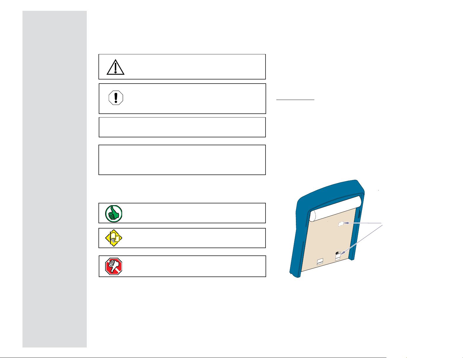
Serial Number Location
General Information
Indicates the function / component is working properly.
No action required.
Indicates the function / component is working,
but a problem exists.
Indicates the function / component is not working at all.
MA731100i
Serial / Model
Number Label
(exact location may vary)
© Midmark Corporation 2003 SF-1838
iii
Rev. 8/24/12
Page 4

General Information
Go To Table Of Contents
Specifications
Patient Weight (maximum) ................................400 lbs (181.4 kgs)
Paper Roll (maximum size): ..............................21 in. long x 3.5 in. diameter
(53.3 x 8.9 cm)
Export models ....................................................19.7 in. long x 4.7 in. diameter
(50 cm x 12 cm)
Range of Motion .................................................
Dimensions .........................................................
See illustration on this page
See illustration on next page
Max.
37 +0.5 in.
(94 +1.3 cm)
Weight of Table:
[230 VAC models only: 230 V transformer adds 14.5 lbs (6.5 kg)]
w/ upholstery .....................................................325 lbs (147.4 kg)
w/packaging & skid
Weight of Upholstery:
w/packaging
Power Cord(s)
Electrical Rating: ................................................
Foot Control Voltage: ......................................... 14 VAC, SELV (Safety Extra Low Voltage)
Duplex Receptacle
maximum load: .................................................
Fuses: ..................................................................Refer to:
Duty Cycle
:
Actuator motor run time
(Domestic: 30 seconds ON / 5 minutes OFF)
(Export: 25 seconds ON / 7 minutes OFF)
Receptacle / Drawer Heater / Uph. Htr
Classifications: ...................................................Class I, Type B Applied Part,
Ordinary Equipment, Intermittent Operation
(Domestic: 30 seconds ON / 5 minutes OFF)
(Export: 25 seconds ON / 7 minutes OFF)
(no upholstery) .................
(shipped separately) .................
[115V models have two cords]
: ...................................... Intermittent Operation
: ......8 ft. (243.8 cm) long
: .............. Continuous Operation
375 lbs (192.7 kg)
40 lbs (18.1 kg)
See Compliance Charts
115 VAC, 5A
Section E - Fuses
623 only
Home Height
20 +0.5 in.
(50.8 +1.3 cm)
0° (horizontal) to
+80° +5°
Min.
18 +0.5 in.
(45.7 +1.3 cm)
Pelvic Tilt
(optional)
Max: 7° +2°
Min: 1.5°
Protection against ingress of fluids: ................ IPX0
Regulatory Compliance: ....................................
Table Speeds
Base ...................................................................... 14 - 26 seconds
Back
(models w/power back) ...............................
iv
© Midmark Corporation 2003 SF-1838
(by function):
Rev. 12/18/12
See Regulatory Compliance Charts
15 - 20 seconds
[Foot Control only: IPX1]
MA599801i
Page 5

Model Identification / Compliance Chart - 222
Go To Table Of Contents
General Information
ledoM noitpircseD
100-222elbaTcisaBrettiR
200-222 elbaTcisaBrettiR
300-222elbaTcisaBrettiR
400-222 elbaTcisaBrettiR
500-222elbaTcisaBrettiR
600-222 elbaTcisaBrettiR
700-222elbaTcisaBrettiR
800-222 elbaTcisaBrettiR
900-222elbaTtropxEcisaBrettiR
010-222 elbaTtropxEcisaBrettiR
110-222)adanaC(elbaTcisaBrettiR
laireS
rebmuN
LU
xiferP
)poTdradnatS(
)poTdradnatS(elcatpeceR/w
)poTdradnatS(tliTcivleP,retaeHrewarD/w
tliTcivleP,elcatpeceR/w
)poTdradnatS(,retaeHrewarD
)poTsselmaeS(
)poTsselmaeS(,elcatpeceR/w
)poTsselmaeS(tliTcivleP,retaeHrewarD/w
tliTcivleP,elcatpeceR/w
)poTsselmaeS(,retaeHrewarD
)poTsselmaeS(tliTcivleP/w
)poTsselmaeS(retaeHrewarD,tliTcivleP/w
)poTdradnatS(elcatpeceR/w
V,GRXX XXX
V,HR
V,JRXX XXX
V,KR X X X
V,GRXX XXX
V,HR
V,JRXX XXX
V,KR X X X
V,LRXXX
V,MR
VX XX
1-10606
ASC/NAC
,2.22
09M-1.106#
:oTseilpmoC :sgnitaRlacirtcelE
LU
NE
445
X X
X X
1-10606
X X
NE
2-1-10606
)CME(
EC
X
X
X
CAV
-/+
spmA
%01
5115.506/05
511 5.01 06/05
5116 06/05
511 11 06/05
5115.506/05
511 5.01 06/05
5116 06/05
511 11 06/05
03257.206/05
032 3 06/05
5115.0106/05
Fire Code Ratings:
All upholstery complies with California Bureau of
Home Furnishing Technical Bulletin 117.
selcyC
Optional upholstery is available that complies
)zH(
with California Bureau of Home Furnishing Technical
Bulletin 133.
210-222 )adanaC(elbaTcisaBrettiR
310-222)adanaC(elbaTcisaBrettiR
410-222
510-222elbaTcisaBrettiR
610-222
710-222
X
511 11 06/05
5115.0106/05
511 11 06/05
5115.0106/05
511 11 06/05
03257.206/05
)poTdradnatS(
retaeHrewarD,tliTcivleP,elcatpeceR/w
)poTsselmaeS(elcatpeceR/w
elbaTcisaBrettiR)adanaC(
retaeHrewarD,tliTcivleP,elcatpeceR/w
)poTsselmaeS(
elcatpeceR/w
elbaTcisaBrettiR
retaeHrewarD,tliTcivleP,elcatpeceR/w
tropxE-elbaTcisaBrettiR
tliTcivleP/w
V X X X
VX XX
V X X X
VX X XXX
V X X X X X
V
XX XX
v
© Midmark Corporation 2003 SF-1838
Page 6

General Information
Go To Table Of Contents
Model Identification / Compliance Chart - 223
ledoM noitpircseD
100-322
200-322
300-322
400-322
500-322
600-322
700-322
800-322
900-322
010-322
110-322
210-322
310-322
410-322
510-322
610-322
)poTdradnatS(
)poTsselmaeS(
elbaTtropxE
elbaTtropxE
elcatpeceR/w
laireS
rebmuN
LU
xiferP
elbaTkcaBrewoPrettiR
elbaTkcaBrewoPrettiR
)poTdradnatS(elcatpeceR/w
elbaTkcaBrewoPrettiR
)poTdradnatS(tliTcivleP,retaeHrewarD/w
elbaTkcaBrewoPrettiR
tliTcivleP,elcatpeceR/w
)poTdradnatS(,retaeHrewarD
elbaTkcaBrewoPrettiR
elbaTkcaBrewoPrettiR
)poTsselmaeS(elcatpeceR/w
elbaTkcaBrewoPrettiR
)poTsselmaeS(tliTcivleP,retaeHrewarD/w
elbaTkcaBrewoPrettiR
tliTcivleP,elcatpeceR/w
)poTsselmaeS(,retaeHrewarD
kcaBrewoPrettiR
)poTsselmaeS(tliTcivleP/w
kcaBrewoPrettiR
)poTsselmaeS(retaeHrewarD,tliTcivleP/w
elbaTkcaBrewoPrettiR)adanaC(
)poTdradnatS(elcatpeceR/w
elbaTkcaBrewoPrettiR)adanaC(
tliTcivleP,elcatpeceR/w
)poTdradnatS(,retaeHrewarD
elbaTkcaBrewoPrettiR)adanaC(
)poTsselmaeS(elcatpeceR/w
elbaTkcaBrewoPrettiR)adanaC(
tliTcivleP,elcatpeceR/w
)poTsselmaeS(,retaeHrewarD
elbaTkcaBrewoPrettiR
elbaTkcaBrewoPrettiR
retaeHrewarD,tliTcivleP,elcatpeceR/w
V,CSXX XXX
V,DS X
V,ESXX XXX
V,FS X
V,CSXX XXX
V,DS X
V,ESXX XXX
V,FS X
V,GSXXX
V,HS X X X
VX
V X
VX
V X
VX X X XX
V
1-10606
X X X X
ASC/NAC
,2.22
09M-1.106#
:oTseilpmoC :sgnitaRlacirtcelE
LU
NE
445
1-10606
NE
2-1-10606
)CME(
X
X
X
X
X
X
X
X
EC
X
X
X
X
X
X
X
X
X
CAV
-/+
%01
spmA
5117 06/05
511 21 06/05
5115.706/05
511 5.21 06/05
5117 06/05
511 21 06/05
5115.706/05
511 5.21 06/05
03257.306/05
032 4 06/05
5112106/05
511 5.21 06/05
5112106/05
511 5.21 06/05
5112106/05
511 5.21 06/05
Fire Code Ratings:
All upholstery complies with California Bureau of
Home Furnishing Technical Bulletin 117.
selcyC
)zH(
Optional upholstery is available that complies
with California Bureau of Home Furnishing Technical
Bulletin 133.
vi
© Midmark Corporation 2003 SF-1838
Page 7

Model Identification / Compliance Chart - 622 / 623
Go To Table Of Contents
General Information
ledoM noitpircseD
100-226
200-226
300-226
400-226
500-226
600-226
700-226
800-226
100-326
200-326
300-326
400-326
500-326
600-326
700-326
800-326
900-326
010-326
elcatpeceR/w
tliTcivleP/w
elcatpeceR/w
elcatpeceR/w
elcatpeceR/w
tliTcivleP/w
elcatpeceR/w
elcatpeceR/w
tliTcivleP/w
laireS
rebmuN
xiferP
elbaTkcaBlaunaMkramdiM
elbaTkcaBlaunaMkramdiM
,tliTcivleP,retaeHrewarD,elcatpeceR/w
yretslohpUdetaeH&
elbaTkcaBlaunaMkramdiM
elbaTkcaBlaunaMkramdiM
yretslohpUdetaeH&,tliTcivleP,retaeHrewarD/w
elbaTkcaBlaunaMkramdiM)adanaC(
elbaTkcaBlaunaMkramdiM)adanaC(
,tliTcivleP,retaeHrewarD,elcatpeceR/w
yretslohpUdetaeH&
elbaTkcaBlaunaMkramdiM
elbaTkcaBlaunaMkramdiM
,tliTcivleP,retaeHrewarD,elcatpeceR/w
yretslohpUdetaeH&
elbaTkcaBrewoPkramdiM
elbaTkcaBrewoPkramdiM
tliTcivleP,elcatpeceR/w
yretslohpUdetaeH&,retaeHrewarD
elbaTkcaBrewoPkramdiM
elbaTkcaBrewoPkramdiM
yretslohpUdetaeH&,retaeHrewarD,tliTcivleP/w
elbaTkcaBrewoPkramdiM)adanaC(
elbaTkcaBrewoPrettiR)adanaC(
tliTcivleP,elcatpeceR/w
yretslohpUdetaeH,retaeHrewarD
elbaTkcaBrewoPkramdiM
elbaTkcaBrewoPkramdiM
tliTcivleP,elcatpeceR/w
yretslohpUdetaeH&,retaeHrewarD
elbaTkcaBrewoPkramdiMtropxE-
elbaTkcaBrewoPkramdiMtropxE-
yretslohpUdetaeH&,retaeHrewarD,tliTcivleP/w
V,JSXXX
V,KS X
V,NSXX XXX
V,PS
VX XX
V
VX X XXX
V
V,LSXXX
V,MS X
V,RS
V,SS
VX
V X
VX X XXX
V
VX X XXX
V
LU
1-10606
X X X X
X X X X X
XX
X X
X X X X X
X X X X X
ASC/NAC
,2.22
09M-1.106#
X X
:oTseilpmoC :sgnitaRlacirtcelE
LU
NE
445
1-10606
NE
2-1-10606
EC
)CME(
X
X
X
X
X
X
XX
X X
X
X
X
X
CAV
-/+
spmA
%01
5115.0106/05
511 5.11 06/05
03257.206/05
032 52.3 06/05
5115.0106/05
511 5.11 06/05
5115.0106/05
511 5.11 06/05
5115.2106/05
511 5.31 06/05
03257.306/05
032 52.4 06/05
5115.2106/05
511 5.31 06/05
5115.2106/05
511 5.31 06/05
03257.306/05
032 52.4 06/05
All upholstery complies with California Bureau of
Home Furnishing Technical Bulletin 117.
selcyC
Optional upholstery is available that complies
)zH(
with California Bureau of Home Furnishing Technical
Bulletin 133.
Fire Code Ratings:
© Midmark Corporation 2003 SF-1838
vii
Page 8
General Information
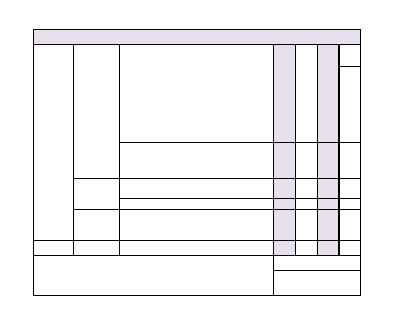
Interval
Inspection or
Service
Service, Adjust , Repair
and / or Replace as Required
(Refer to appropriate S&P or Quick Reference Guide)
222 223 622 623
Clean upholstery with diluted bleach solution.
10:1 (water:bleach)
X X X X
Wipe painted metal & plastic surfaces with a clean soft cloth and
mild cleaner. (NOTE: Periodic application of common furniture
wax will ease cleaning, and maintain the luster of the surfaces).
X X X X
Obvious Damage
Visually inspect components for damage that could cause
problems during operation or unsafe operation.
X X X X
Check all mechanical functions using the foot control. Repeat
using the hand control when present.
X X X X
Check manual back releaase mechanism for proper operation.
X X X X
Table shrouds should move smoothly & quietly when base is
raised & lowered. (NOTE: There are plastic glides on the shroud
tabs. Missing glides may result in noisy operation.)
X X X X
Labels / Decals Replace any missing or illegible labels.
X X X X
Lubricate back hinge with light machine oil.
X X X X
Lubricate footrest slide with household furniture wax.
X X X X
Hardware All fasteners must be present and fastened securely.
X X X X
Inspect power cord and all wiring for damage.
X X X X
Be sure all electrical connections are tight.
X X X X
Stirrups
Check that stirrups extend easily, and lock securely into each
lateral position.
X X X X
Date of Service: _____/____/____
Location:
Service
Technician:
Serial Number:
Mechanical
Operation
Semi-Annually
Lubricate
Scheduled Maintenance / Barrier-Free® Examination Table
Weekly
Cleaning
Electrical System
Model:
Go To Table Of Contents
viii
© Midmark Corporation 2003 SF-1838
Rev. 10/24/12
Page 9

Warranty Information
Go To Table Of Contents
General Information
SCOPE OF WARRANTY
Midmark Corporation (“Midmark”) warrants to the original purchaser its new Alternate Care
products and components (except for components not warranted under “Exclusions”)
manufactured by Midmark to be free from defects in material and workmanship under normal use
and service. Midmark’s obligation under this warranty is limited to the repair or replacement, at
Midmark’s option, of the parts or the products the defects of which are reported to Midmark
within the applicable warranty period and which, upon examination by Midmark, prove to be
defective.
APPLICABLE WARRANTY PERIOD
The applicable warranty period, measured from the date of delivery to the original user, shall be
one (1) year for all warranted products and components.
EXCLUSIONS
This warranty does not cover and Midmark shall not be liable for the following: (1) repairs and
replacements because of misuse, abuse, negligence, alteration, accident, freight damage, or
tampering; (2) products which are not installed, used, and properly cleaned as required in the
Midmark “Installation” and or “Installation / Operation Manual for this applicable product. (3)
products considered to be of a consumable nature; (4) accessories or parts not manufactured
by Midmark; (5) charges by anyone for adjustments, repairs, replacement parts, installation, or
other work performed upon or in connection with such products which is not expressly
authorized in writing in advance by Midmark.
EXCLUSIVE REMEDY
Midmark’s only obligation under this warranty is the repair or replacement of defective parts.
Midmark shall not be liable for any direct, special, indirect, incidental, exemplary, or
consequential damages or delay, including, but not limited to, damages for loss of profits or loss
of use.
NO AUTHORIZATION
No person or firm is authorized to create for Midmark any other obligation or liability in
connection with the products.
Additional Information
Failure to follow the guidelines listed below will void the
warranty and/or render the table unsafe for use.
• If a malfunction is detected, do not use the table until
necessary repairs are made.
• Do not attempt to disassemble table, replace
components, or perform adjustments unless you are
a Midmark authorized service technician.
• Do not use another manufacturer's parts to replace
malfunctioning components. Use only Midmark
replacement parts
THIS WARRANTY IS MIDMARK’S ONLY WARRANTY AND IS IN LIEU OF ALL OTHER
WARRANTIES, EXPRESS OR IMPLIED. MIDMARK MAKES NO IMPLIED WARRANTIES OF
ANY KIND INCLUDING ANY WARRANTIES OF MERCHANTABILITY OR FITNESS FOR ANY
PARTICULAR PURPOSE. THIS WARRANTY IS LIMITED TO THE REPAIR OR REPLACE
MENT OF DEFECTIVE PARTS.
SF-1487 REV. A1
© Midmark Corporation 2003 SF-1838
ix
Page 10
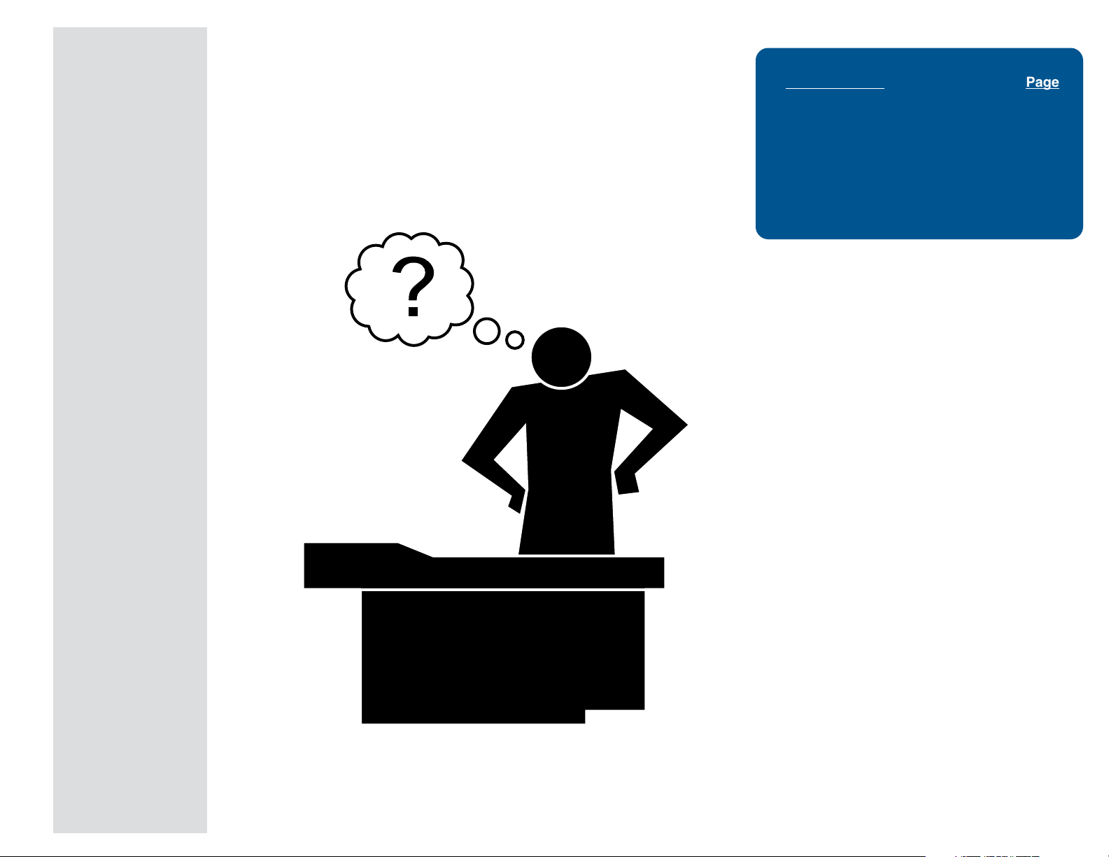
Troubleshooting
Go To Table Of Contents
Click on the Go To Page button and enter the desired
page number. (Note: Letters are case sensitve. ex. A-2)
Go To Page:
Troubleshooting
Table Function Page
Base Up / Down ................................... A-2
Back Up / Down .................................... A-11
Drawer Heater ....................................... A-23
Table Receptacle .................................. A-27
Auto Return .......................................... A-29
Upholstery Heater System.................... A-32
Section A
Models:
Serial Numbers:
© Midmark Corporation 2003 SF-1838
A-1
Page 11
Troubleshooting
Go To Table Of Contents
Go To Page:
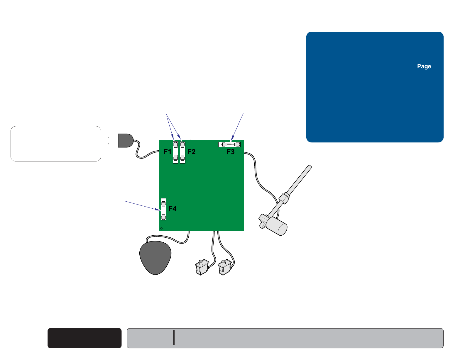
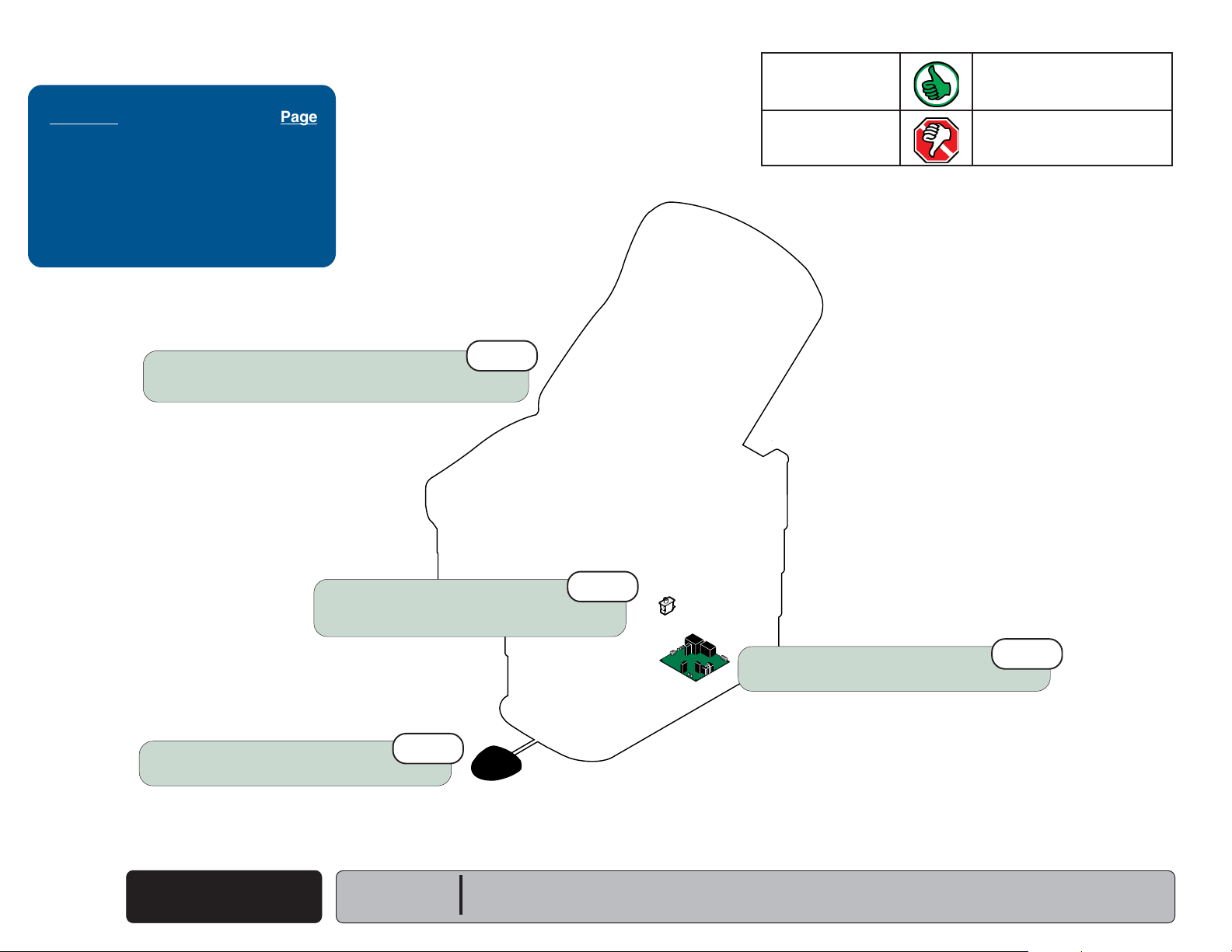
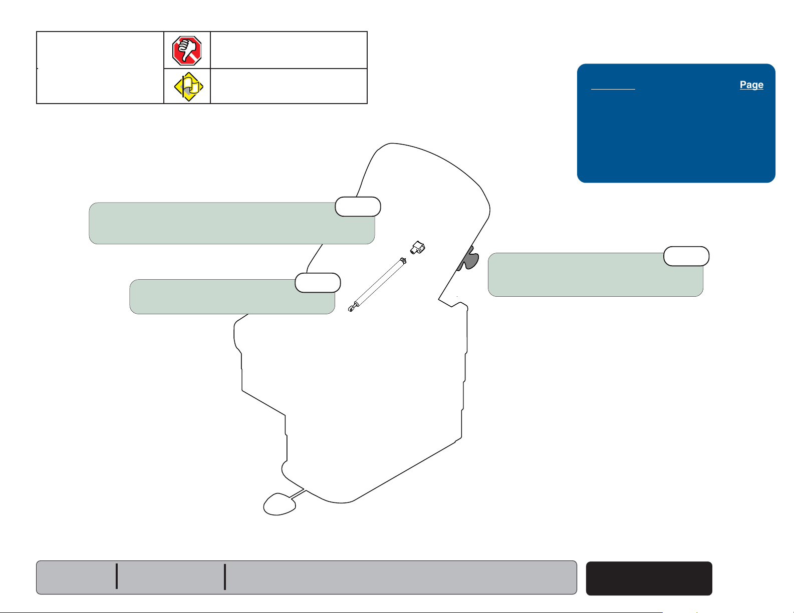
Base UP / DOWN Function
This illustration shows only the components that affect the Base UP / DOWN function.
Refer to the following page for a detailed description of current flow during this function.
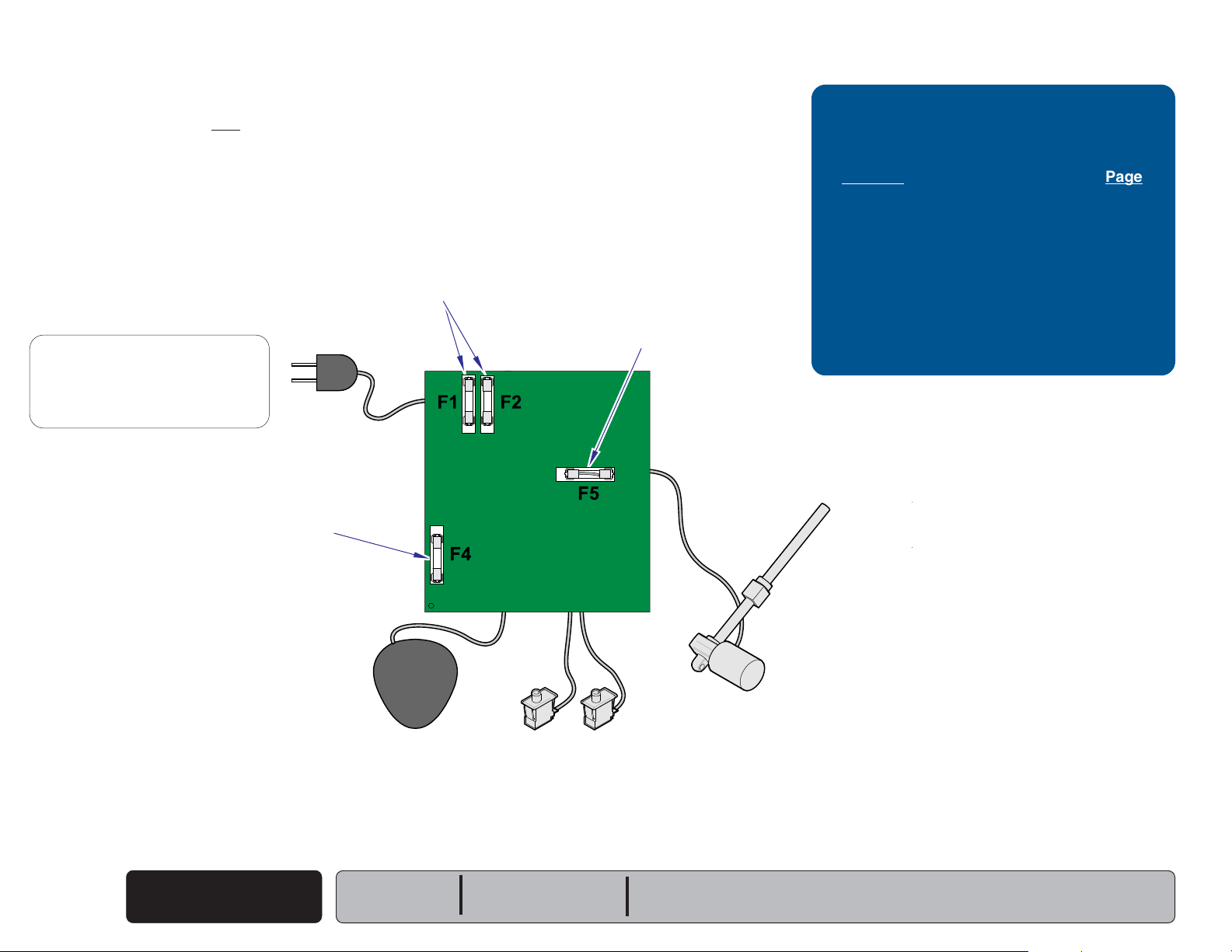
Primary Fuses
NOTE:
Line voltage (230 VAC) is supplied thru
two fuses
inlet)
line voltage to 115 VAC before it
reaches the PC Board.
230 VAC models only
(located by the power cord
to a transformer that reduces the
[All Functions]
115 VAC
[Base Up & Down Functions]
Base Motor Fuse
Troubleshooting
[Base Up / Down Function]
Problem Page
No UP or DOWN Functions
No UP Function (DOWN - OK)
No DOWN Function (UP - OK)
Base Drifts Down .................................
Moves Wrong Direction .......................
Noisy Operation ...................................
Moves Slowly ....................................
................ A-4
............ A-5
............ A-6
A-7
A-8
A-9
A-10
A-2
© Midmark Corporation 2003 SF-1838
Transformer Fuse
[All Functions]
Foot Control
Base Up / Down
Main PC Board
14 VAC
Base Up Limit Switch
[Base Up will not operate if switch is tripped]
Models:
Serial Numbers:
All
All
48 VDC
MA627300i
Base Actuator
Base Down Limit Switch
[Base Down will not operate if switch is tripped]
Page 12
Troubleshooting
Go To Table Of Contents
Base UP / DOWN Function
NOTE
On 230 VAC models, line voltage
supplied thru two fuses
to a transformer that reduces the line voltage
to 115 VAC before it gets to the PC board.
Power To Foot Control
115 VAC is supplied thru the two primary fuses
(F1 & F2)
[F4 fuse protects the transformer]
The transformer reduces the line voltage and
supplies 14 VAC to the foot control.
to the transformer on the PC board.
(located by IEC inlet)
(230 VAC)
.
is
Base Up Operation
NOTE
If the Base Up limit switch is tripped (open),
the Base Up function will not operate.
When the Base Up function is activated,
current
switch
on the PC Board energizes the base relay.
[F3 fuse protects the base motor]
(14 VAC)
(N.O)
flows thru the Up function foot
, then back to the PC board. Circuitry
.
NOTE
The Base Up/Down relay has four contacts:
(2) Normally Open: Base Up function
(2) Normally Closed: Base Down function
When the base relay is energized,
the (2) Normally Open contacts of the relay
close. When these contacts close, current
(
48 VDC)
When current flows to the actuator thru the
Normally Open contacts of the relay, the actuator
motor runs and raises the table.
Actuator Motor runs until:
1. Foot control pedal is released.
2. Base Up limit switch is tripped.
3. 26 second software time limit is reached.
4. Fuse(s) opens (blows).
flows to the actuator motor.
[Primary, Base Motor, Transformer fuse]
Base Down Operation
NOTE
If the Base Down limit switch is tripped (open),
the Base Down function will not operate.
When the Base Down function is activated,
current
switch
(14 VAC)
(N.O.)
flows thru the Down function foot
, then back to the PC Board.
NOTE
The Base Up/Down relay has four contacts:
(2) Normally Open: Base Up function
(2) Normally Closed: Base Down function
When this voltage is applied, current
to the actuator motor thru the (2) Normally Closed
contacts of the Base Up/Down relay.
[The relay does not energize].
When voltage flows to the actuator thru the Normally
Closed contacts of the relay, the actuator motor runs
andlowers the table.
Actuator Motor runs until:
1. Foot control pedal is released.
2. Base Down limit switch is tripped.
3. 26 second software time limit is reached.
4. Fuse(s) opens (blows).
[Primary, Base Motor, Transformer fuse]
(48 VDC)
flows
Models:
Serial Numbers:
All
All
Equipment Alert
If an overload condition* is detected the PC board will "beep" and all power functions will be
disabled. Release the function button, remove load, then retry function.
*(weight limit exceeded, mechanical binding, etc),
Base Up / Down
© Midmark Corporation 2003 SF-1838
Rev. 8/24/12
A-3
Page 13
Troubleshooting
Go To Table Of Contents
Go To Page:
Refer To: Page
Fuses ........................................... B-2
Limit Switches.............................. B-4
Foot Control ................................. B-6
Base / Back Actuator ................... B-11
Base Relay Test .......................... B-20
Wiring Diagrams ............................ D-1
Exploded Views / Part Numbers ....E-1
Loose Wire Connections
(esp. Foot Control & Base Up/Down Limit Switches)
1st
noitcnuFsutatSmelborP
Base Up No movement
Base Down No movement
Perform
Refer to: Section B - Foot Control
Footswitch Test
A-4
© Midmark Corporation 2003 SF-1838
Base Actuator
To isolate the malfunction,
Refer to: Section B - Base / Back Actuator
3rd
Base Up / Down
Rev. 2/08
Serial Numbers:
4th
Models:
MA626600i
All
All
230 V models only
230 VAC
Transformer Fuses (2)
Refer to: Section B - Fuses
230 VAC Transformer
Main PC Board Fuse(s):
[Test fuses: F1, F2, F3, & F4]
Refer to: Section B - Fuses
Perform
Refer to: Section B - Main PC Board
Base Relay Test
230 V models only
2nd
5th
Page 14
noitcnuFsutatSmelborP
Go To Table Of Contents
Go To Page:
Base Up No movement
Base Down OK
Loose Wire Connections
(esp. Foot Control & Base Up/Down Limit Switches)
1st
Troubleshooting
Refer To: Page
Limit Switches.............................. B-4
Footswitch Test ........................... B-6
Base Relay Test .......................... B-20
Wiring Diagrams ............................ D-1
Exploded Views / Part Numbers ....E-1
Perform
Refer to: Section B - Foot Control
Models:
Serial Numbers:
Base Up Limit Switch
Perform
Refer to: Section B - Limit Switches
Footswitch Test
Limit Switch Test.
3rd
All
All
2nd
MA626800i
Perform
Refer to: Section B - Main PC Board
Base Relay Test
© Midmark Corporation 2003 SF-1838
4th
Base Up / Down
Rev. 2/08
A-5
Page 15
Troubleshooting
Go To Table Of Contents
Go To Page:
Refer To: Page
Limit Switches.............................. B-4
Foot Control ................................. B-6
Base Relay Test .......................... B-20
Wiring Diagrams ............................ D-1
Exploded Views / Part Numbers ....E-1
Loose Wire Connections
(esp. Foot Control & Base Down Limit Switches)
1st
noitcnuFsutatSmelborP
Base Up OK
Base Down No movement
Perform
Refer to: Section B - Foot Control
A-6
© Midmark Corporation 2003 SF-1838
Footswitch Test
Base Up / Down
Base Down Limit Switch
Perform
Refer to: Section B - Limit Switches
Rev. 2/08
Limit Switch Test.
3rd
Models:
Serial Numbers:
All
All
2nd
MA626700i
Perform
Refer to: Section B - Main PC Board
Base Relay Test
4th
Page 16

noitcnuFsutatSmelborP
Go To Table Of Contents
Go To Page:
Base Up Table drifts down.
Base Down Table drifts down.
Run table up, then unplug power cord.
If drifting stops, perform
If drifting continues, check Base Actuator.
Footswitch Test
.
1st
Troubleshooting
Refer To: Page
Foot Control ................................. B-6
Base / Back Actuator ................... B-11
Wiring Diagrams ............................ D-1
Exploded Views / Part Numbers ....E-1
Models:
Serial Numbers:
Perform
Refer to: Section B - Foot Control
Footswitch Test
All
All
MA626900i
Base Actuator
To isolate the malfunction,
Refer to: Section B - Base / Back Actuator
© Midmark Corporation 2003 SF-1838
Base Up / Down
A-7
Page 17
Troubleshooting
Go To Table Of Contents
Go To Page:
Refer To: Page
Main PC Board Replacement ....... B-22
Wiring Diagrams ............................ D-1
Exploded Views / Part Numbers ....E-1
noitcnuFsutatSmelborP
Base Up Press Base UP pedal,
table moves DOWN.
Base Down Press Base DOWN pedal,
table moves UP.
A-8
© Midmark Corporation 2003 SF-1838
Wire connections
(Check Foot Control & Base Actuator motor connections)
Base Up / Down
(reversed?)
Models:
Serial Numbers:
1st
All
All
MA627000i
Replace Main PC Board
Refer to: Section B - Main PC Board
2nd
Page 18
noitcnuFsutatSmelborP
Go To Table Of Contents
Go To Page:
Base Up Noisy / grinding / squeaking
Base Down Noisy / grinding / squeaking
Troubleshooting
Refer To: Page
Base Actuator Replacement .........B-11
Table Shroud Removal ..................C-2
Wiring Diagrams ............................ D-1
Exploded Views / Part Numbers ....E-1
Clean and lubricate base actuator threads.
Recommended lubricant: Lithium grease
If necessary, refer to:
Section C - Table Shroud Removal
1st
Remove any debris from base slides.
Do not lubricate base slides.
If necessary, refer to:
Models:
Serial Numbers:
2nd
Section C - Table Shroud Removal
All
All
MA627100i
3rd
Replace Base Actuator
Refer to: Section B - Base / Back Actuator
© Midmark Corporation 2003 SF-1838
Base Up / Down
A-9
Page 19

Troubleshooting
Go To Table Of Contents
Go To Page:
Refer To: Page
Wiring Diagrams .......................... D-1
Exploded Views / Part Numbers .. E-1
Did patient exceed 400 lb. weight limit?
Inform staff that max. patient weight is 400 lbs.
1st
noitcnuFsutatSmelborP
Base Up Moves slowly
Base Down Moves slowly
A-10
© Midmark Corporation 2003 SF-1838
Base Up / Down
Models:
Serial Numbers:
All
All
MA627200i
Low voltage to table
Required voltage:
115 VAC models ............... 115
230 VAC models .............. 230
2nd
+10% VAC
+10% VAC
Page 20

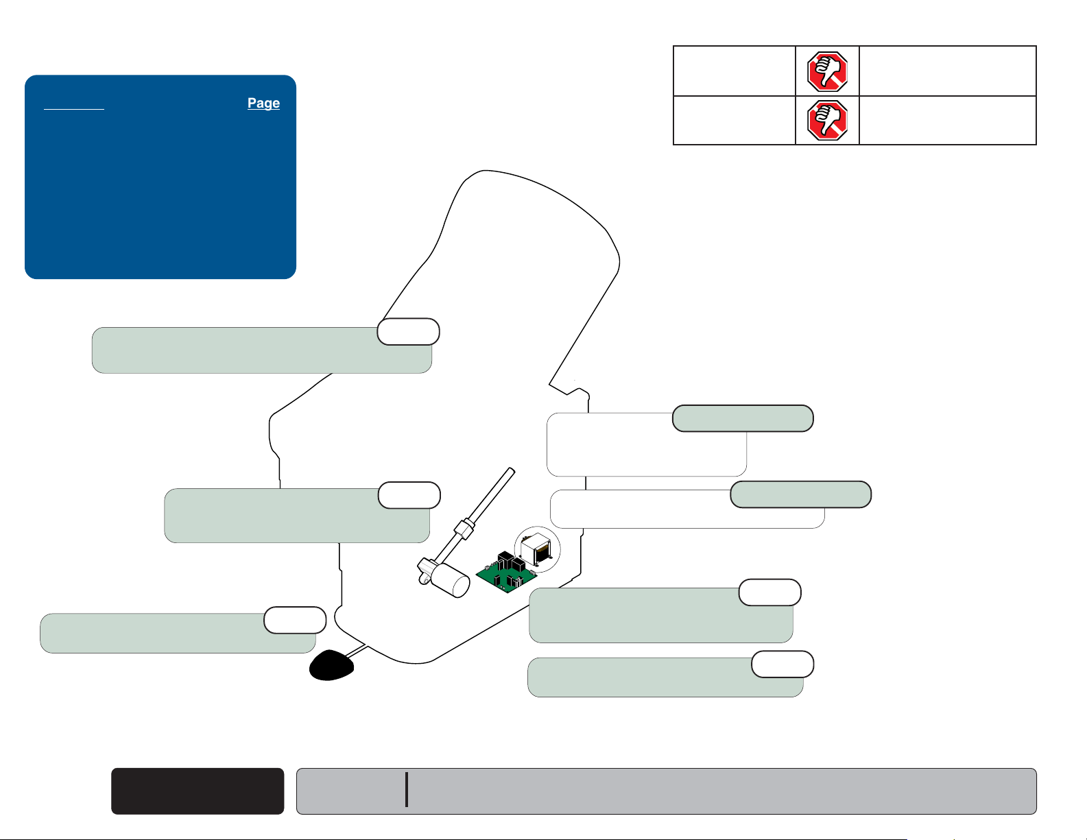
MA630300i
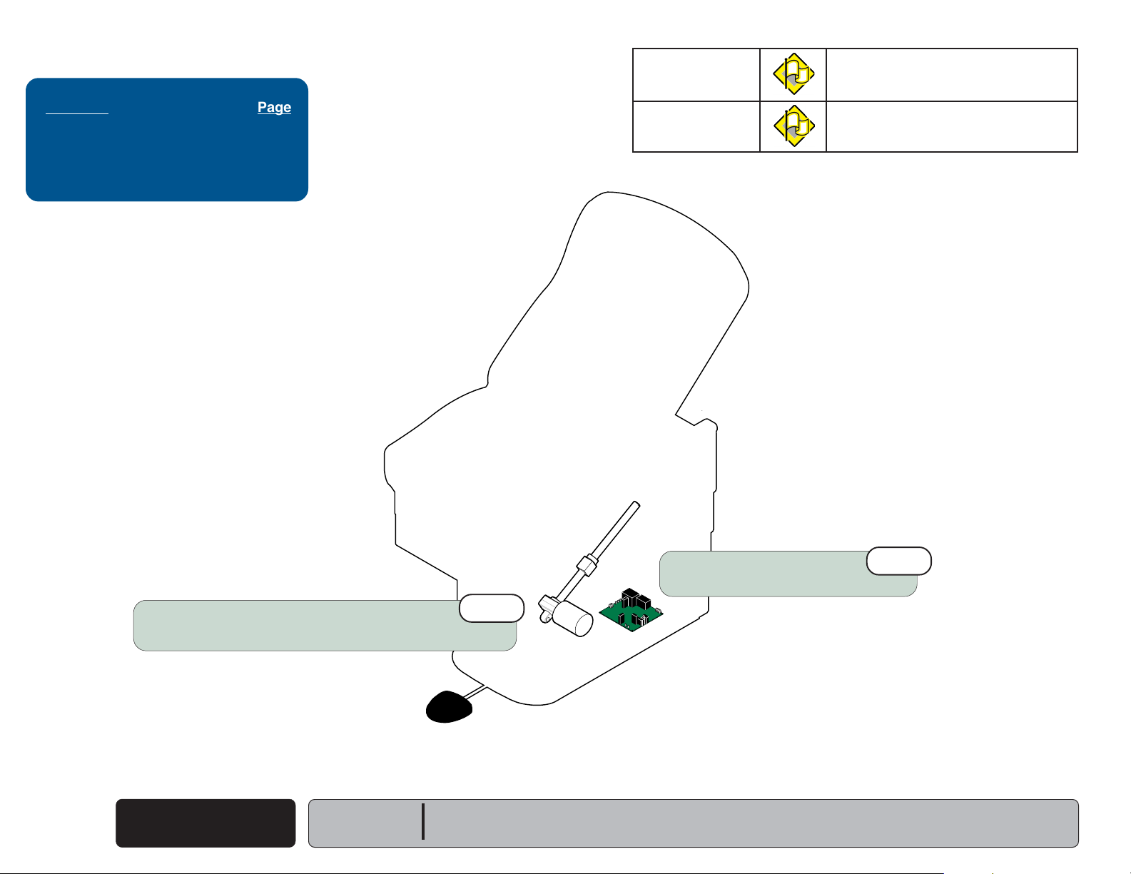
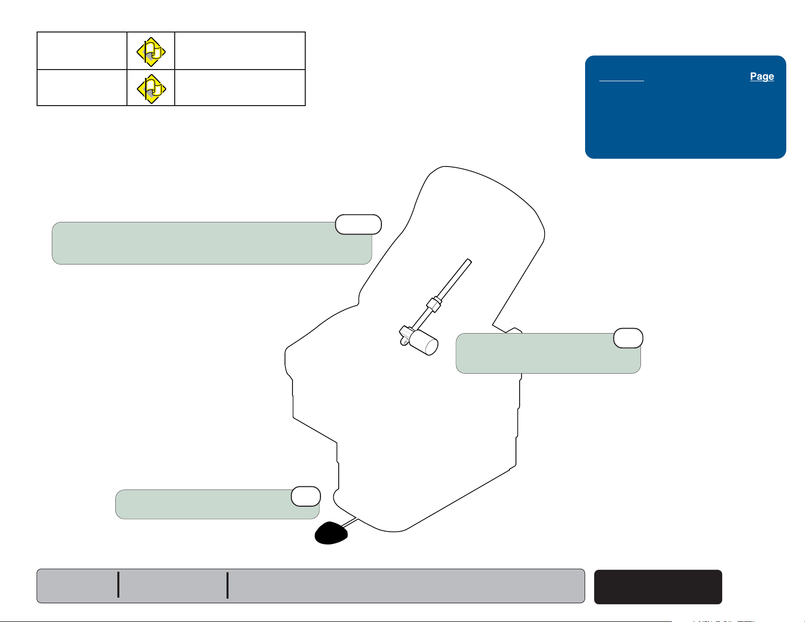
Back UP / DOWN Function (Manual)
Go To Table Of Contents
Go To Page:
This illustration shows only the components that affect the Back UP / DOWN function.
Cam
Troubleshooting
Troubleshooting
[Back Up / Down Function (Manual)]
Problem Page
Back Drifts Up or Down .....................
No Movement ....................................
Difficult To Position ............................
A-12
A-13
A-13
Back Up / Down Operation
When either back release handle is squeezed,
linkage causes the cam to rotate. When the cam
compresses the pin on the top of the gas
cylinder, the pressure inside the cylinder is
released and the back section can be positioned
Up or Down.
Back Release
Handle
(Manual)
Gas Cylinder
Models:
Serial Numbers:
222 (all)
All
622 (all)
All
Back Up / Down
Manual
© Midmark Corporation 2003 SF-1838
A-11
Page 21
Troubleshooting
Go To Table Of Contents
Go To Page:
Refer To: Page
Back Release Handle
Adjustment ............................. B-17
Gas Cylinder
Replacement & Adjustment.... B-18
Exploded Views / Part Numbers .. E-1
Gas cylinder screwed in too far.
Perform Gas Cylinder Adjustment
Refer to: Section B - Back Release Mechanism
1st
noitcnuFsutatSmelborP
Back Up/Down Back section drifts
2nd
Perform
Handle Adjustment
Refer to: Section B - Back Release Mechanism
Replace Gas Cylinder
Refer to: Section B - Back Release Mechanism
Back Release
3rd
A-12
© Midmark Corporation 2003 SF-1838
Back Up / Down
Manual
Models:
Serial Numbers:
222 (all)
All
MA630400i
622 (all)
All
Page 22
noitcnuFsutatSmelborP
Go To Table Of Contents
Go To Page:
Back Up/Down No movement
Troubleshooting
Difficult to position
Gas cylinder not screwed in far enough.
Perform Gas Cylinder Adjustment
Refer to: Section B - Back Release Mechanism
3rd
Replace Gas Cylinder
Refer to: Section B - Back Release Mechanism
1st
Refer To: Page
Back Release Handle
Adjustment ............................. B-17
Gas Cylinder
Replacement & Adjustment.... B-18
Exploded Views / Part Numbers .. E-1
2nd
Perform
Handle Adjustment
Refer to: Section B - Back Release Mechanism
Back Release
Models:
Serial Numbers:
222 (all)
All
622 (all)
All
MA630400i
Back Up / Down
Manual
© Midmark Corporation 2003 SF-1838
A-13
Page 23
Troubleshooting
Go To Table Of Contents
Go To Page:
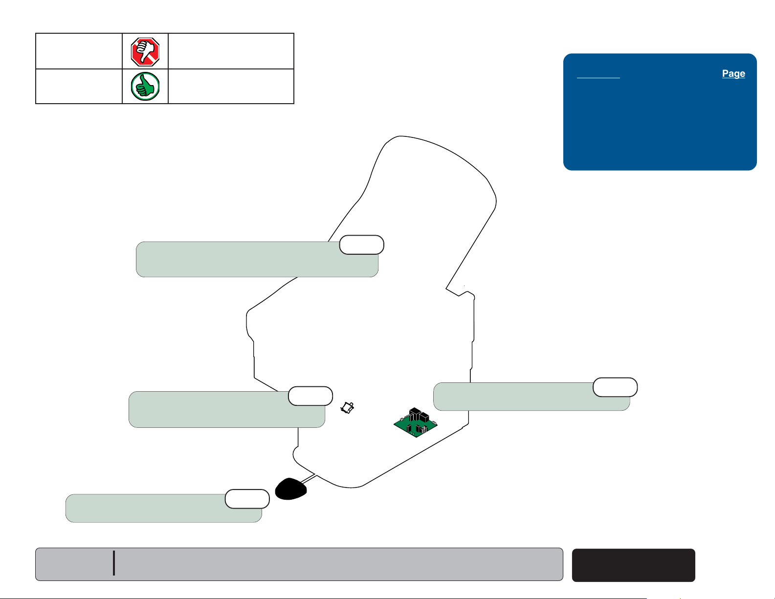
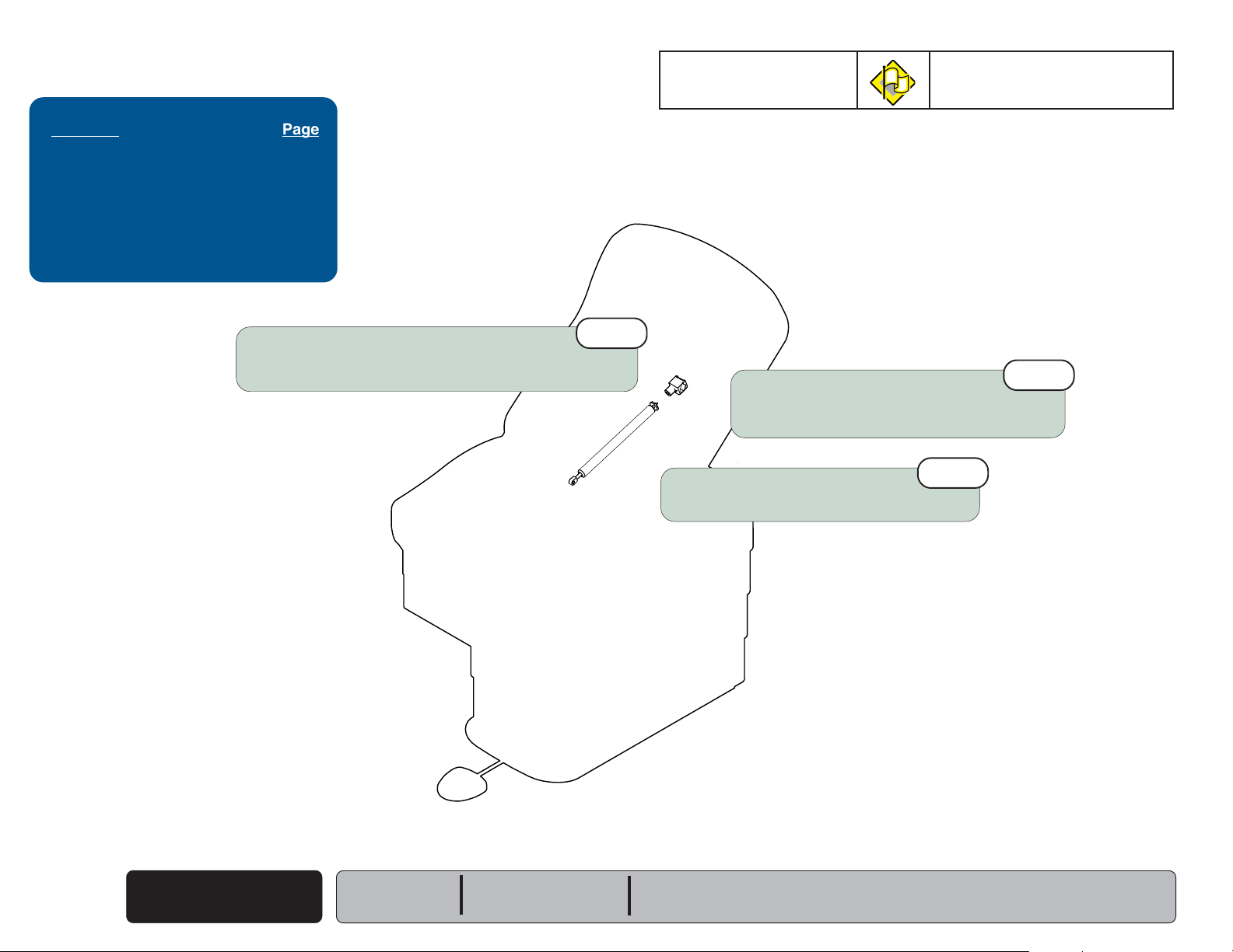
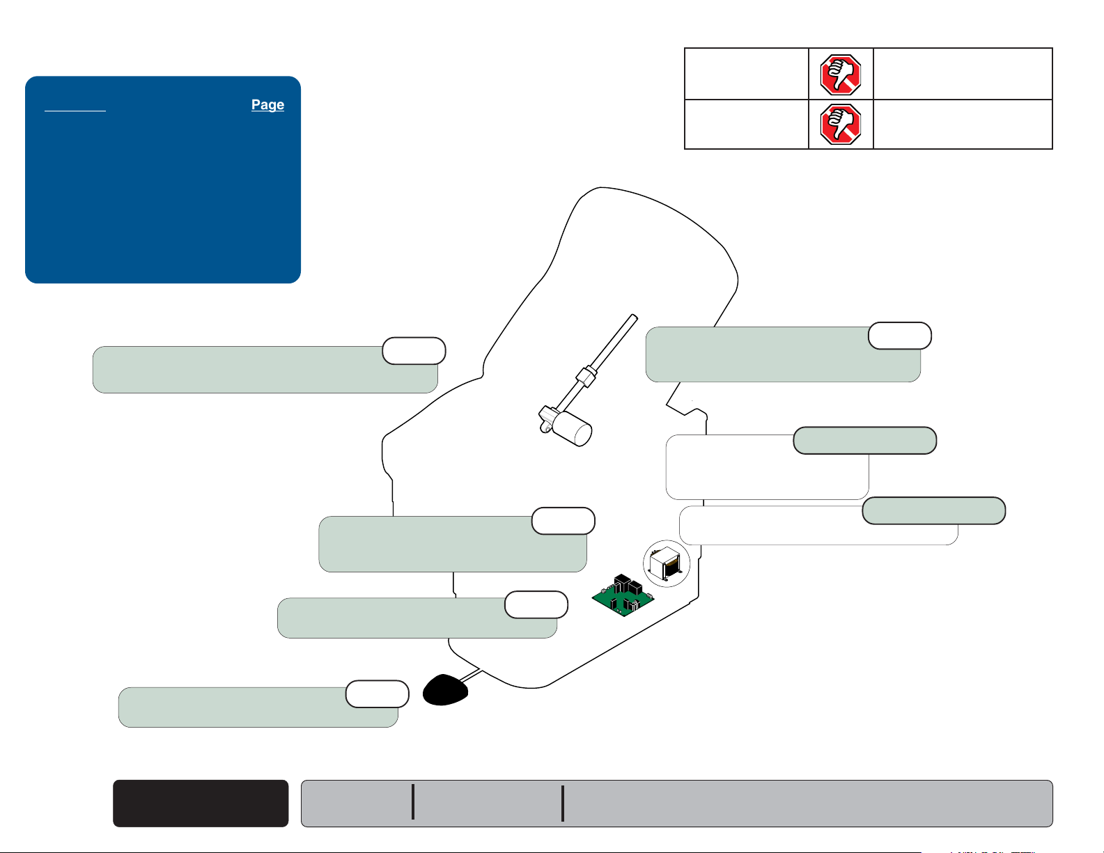
Back UP / DOWN Function (Power)
This illustration shows only the components that affect the Back UP / DOWN function.
Refer to the following page for a detailed description of current flow during this function.
Primary Fuses
[All Functions]
NOTE:
Line voltage (230 VAC) is supplied thru
two fuses
inlet)
line voltage to 115 VAC before it
reaches the PC Board.
230 VAC models only
(located by the power cord
to a transformer that reduces the
115 VAC
[Back Up / Down Functions]
Back Motor Fuse
Troubleshooting
[Back Up / Down Function (Power)]
Problem Page
No UP or DOWN Functions
No DOWN Function (UP - OK)
No UP Function (DOWN - OK)
Back Drifts Down .................................
Moves Wrong Direction .......................
Noisy Operation ...................................
Moves Slowly ......................................
................ A-16
............ A-17
............ A-18
A-19
A-20
A-21
A-22
A-14
© Midmark Corporation 2003 SF-1838
Transformer Fuse
[All Functions]
Back Up / Down
Power
14 VAC
Foot Control
Back Up Limit Switch
[Back Up will not operate if switch is tripped]
Models:
Serial Numbers:
Main PC Board
223 (all)
All
48 VDC
Back Actuator
Back Down Limit Switch
[Back Down will not operate if switch is tripped]
MA630200i
623 (all)
All
Page 24

Troubleshooting
Go To Table Of Contents
Back UP / DOWN Function
(Power)
NOTE
On 230 VAC models, line voltage
supplied thru two fuses
to a transformer that reduces the line voltage
to 115 VAC before it gets to the PC board.
Power To Foot Control
115 VAC is supplied thru the two primary fuses
(F1 & F2)
[F4 fuse protects the transformer]
The transformer reduces the line voltage and
supplies 14 VAC to the foot control.
to the transformer on the PC board.
(located by IEC inlet)
(230 VAC)
.
is
Back Up Operation
NOTE
If the Back Up limit switch is tripped (open),
the Back Up function will not operate.
When the Back Up function is activated,
current
switch
on the PC Board energizes the back relay.
[F5 fuse protects the back motor]
(14 VAC)
(N.O)
flows thru the Up function foot
, then back to the PC board. Circuitry
.
NOTE
The Back Up/Down relay has four contacts:
(2) Normally Open: Back Up function
(2) Normally Closed: Back Down function
When the back relay is energized,
the (2) Normally Open contacts of the relay
close. When these contacts close, current
(
48 VDC)
When current flows to the actuator thru the
Normally Open contacts of the relay, the actuator
motor runs and raises the back section.
Actuator Motor runs until:
1. Foot control pedal is released.
2. Back Up limit switch is tripped.
3. 26 second software time limit is reached.
4. Fuse(s) opens (blows).
flows to the actuator motor.
[Primary, Back Motor, Transformer fuse]
Back Down Operation
NOTE
If the Back Down limit switch is tripped (open),
the Back Down function will not operate.
When the Back Down function is activated,
current
switch
(14 VAC)
(N.O.)
flows thru the Down function foot
, then back to the PC Board.
NOTE
The Back Up/Down relay has four contacts:
(2) Normally Open: Back Up function
(2) Normally Closed: Back Down function
When this voltage is applied, current
to the actuator motor thru the (2) Normally Closed
contacts of the Back Up/Down relay.
[The relay does not energize].
When voltage flows to the actuator thru the Normally
Closed contacts of the relay, the actuator motor runs
and lowers the back section.
Actuator Motor runs until:
1. Foot control pedal is released.
2. Back Down limit switch is tripped.
3. 26 second software time limit is reached.
4. Fuse(s) opens (blows).
[Primary, Back Motor, Transformer fuse]
(48 VDC)
flows
Models:
Serial Numbers:
223 (all)
All
623 (all)
All
Equipment Alert
If an overload condition* is detected the PC board will "beep" and all power functions will be
disabled. Release the function button, remove load, then retry function.
*(weight limit exceeded, mechanical binding, etc),
Back Up / Down
Power
© Midmark Corporation 2003 SF-1838
Rev. 8/24/12
A-15
Page 25
Troubleshooting
Go To Table Of Contents
Go To Page:
Refer To: Page
Fuses ........................................... B-2
Limit Switches.............................. B-4
Foot Control ................................. B-6
Base / Back Actuator ................... B-11
Back Relay Test .......................... B-21
Wiring Diagrams ............................ D-1
Exploded Views / Part Numbers ....E-1
noitcnuFsutatSmelborP
Back Up No movement
Back Down No movement
Loose Wire Connections
(esp. Foot Control & Back Up/Down Limit Switches)
Main PC Board Fuse(s):
[Test fuses: F1, F2, F4, & F5]
Refer to: Section B - Fuses
Perform
Refer to: Section B - Main PC Board
Perform
Refer to: Section B - Foot Control
Footswitch Test
Back Relay Test
3rd
1st
5th
2nd
MA630100i
Back Actuator
To isolate the malfunction,
Refer to: Section B - Base / Back Actuator
230 V models only
230 VAC
Transformer Fuses (2)
Refer to: Section B - Fuses
230 VAC Transformer
4th
230 V models only
A-16
© Midmark Corporation 2003 SF-1838
Back Up / Down
Power
Rev. 5/07
Models:
Serial Numbers:
223 (all)
All
623 (all)
All
Page 26
noitcnuFsutatSmelborP
Go To Table Of Contents
Go To Page:
Back Up OK
Back Down No movement
Loose Wire Connections
(esp. Foot Control & Back Down Limit Switches)
1st
Troubleshooting
Refer To: Page
Limit Switches.............................. B-4
Foot Control ................................. B-6
Back Relay Test ......................... B-18
Wiring Diagrams .......................... D-1
Exploded Views / Part Numbers .. E-1
Perform
Refer to: Section B - Foot Control
Footswitch Test
3rd
MA629200i
Back Down Limit Switch
Perform
Refer to: Section B - Limit Switches
Limit Switch Test.
Perform
Refer to: Section B - Main PC Board
Back Relay Test
2nd
4th
Models:
Serial Numbers:
223 (all)
All
623 (all)
All
Back Up / Down
Power
© Midmark Corporation 2003 SF-1838
A-17
Page 27

Troubleshooting
Go To Table Of Contents
Go To Page:
Refer To: Page
Limit Switches.............................. B-4
Foot Control ................................. B-6
Back Relay Test ......................... B-18
Wiring Diagrams .......................... D-1
Exploded Views / Part Numbers .. E-1
Loose Wire Connections
(esp. Foot Control & Back Up Limit Switches)
1st
noitcnuFsutatSmelborP
Back Up No movement
Back Down OK
Back Up Limit Switch
Perform
Refer to: Section B - Limit Switches
Limit Switch Test.
2nd
A-18
© Midmark Corporation 2003 SF-1838
Perform
Refer to: Section B - Foot Control
Back Up / Down
Power
Footswitch Test
Serial Numbers:
3rd
Models:
223 (all)
All
MA629100i
623 (all)
All
Perform
Refer to: Section B - Main PC Board
Back Relay Test
4th
Page 28
noitcnuFsutatSmelborP
Go To Table Of Contents
Go To Page:
Back Up Back drifts down.
Back Down Back drifts down.
Run back section up, then unplug power cord.
If drifting stops, perform
If drifting continues, check Back Actuator.
Footswitch Test
.
1st
Troubleshooting
Refer To: Page
Foot Control ................................. B-6
Base / Back Actuator .................. B-11
Wiring Diagrams .......................... D-1
Exploded Views / Part Numbers .. E-1
Models:
Serial Numbers:
Perform
Refer to: Section B - Foot Control
Footswitch Test
223 (all)
All
623 (all)
All
MA629300i
Back Actuator
To isolate the malfunction,
Refer to: Section B - Base / Back Actuator
Back Up / Down
© Midmark Corporation 2003 SF-1838
Power
A-19
Page 29
Troubleshooting
Go To Table Of Contents
Go To Page:
Refer To: Page
Main PC Board Replacement ....... B-22
Wiring Diagrams ............................ D-1
Exploded Views / Part Numbers ....E-1
noitcnuFsutatSmelborP
Back Up Press Back UP pedal,
back section moves DOWN.
Back Down Press Back DOWN pedal,
back section moves UP.
A-20
© Midmark Corporation 2003 SF-1838
Wire connections
(Check Foot Control & Base Actuator motor connections)
Back Up / Down
Power
(reversed?)
Models:
Serial Numbers:
1st
223 (all)
All
MA629400i
Replace Main PC Board
Refer to: Section B - Main PC Board
623 (all)
All
2nd
Page 30

noitcnuFsutatSmelborP
Go To Table Of Contents
Go To Page:
Back Up Noisy / grinding / squeaking
Back Down Noisy / grinding / squeaking
Troubleshooting
Refer To: Page
Back Actuator Replacement ....... B-15
Wiring Diagrams .......................... D-1
Exploded Views / Part Numbers .. E-1
Clean and lubricate back actuator threads.
Recommended lubricant: Lithium grease
[NOTE: Unscrew the shaft cover to access actuator threads.
]
1st
Models:
Serial Numbers:
223 (all)
All
623 (all)
All
MA629500i
3rd
Replace Back Actuator
Refer to: Section B - Base / Back Actuator
Back Up / Down
Power
© Midmark Corporation 2003 SF-1838
A-21
Page 31

Troubleshooting
Go To Table Of Contents
Go To Page:
Refer To: Page
Wiring Diagrams .......................... D-1
Exploded Views / Part Numbers .. E-1
Did patient exceed 400 lb. weight limit?
Inform staff that max. patient weight is 400 lbs.
1st
noitcnuFsutatSmelborP
Back Up Moves slowly
Back Down Moves slowly
2nd
Low voltage to table
Required voltage:
115 VAC models ............... 115
230 VAC models .............. 230
+10% VAC
+10% VAC
A-22
© Midmark Corporation 2003 SF-1838
Back Up / Down
Power
Models:
Serial Numbers:
223 (all)
All
MA627200i
623 (all)
All
Page 32

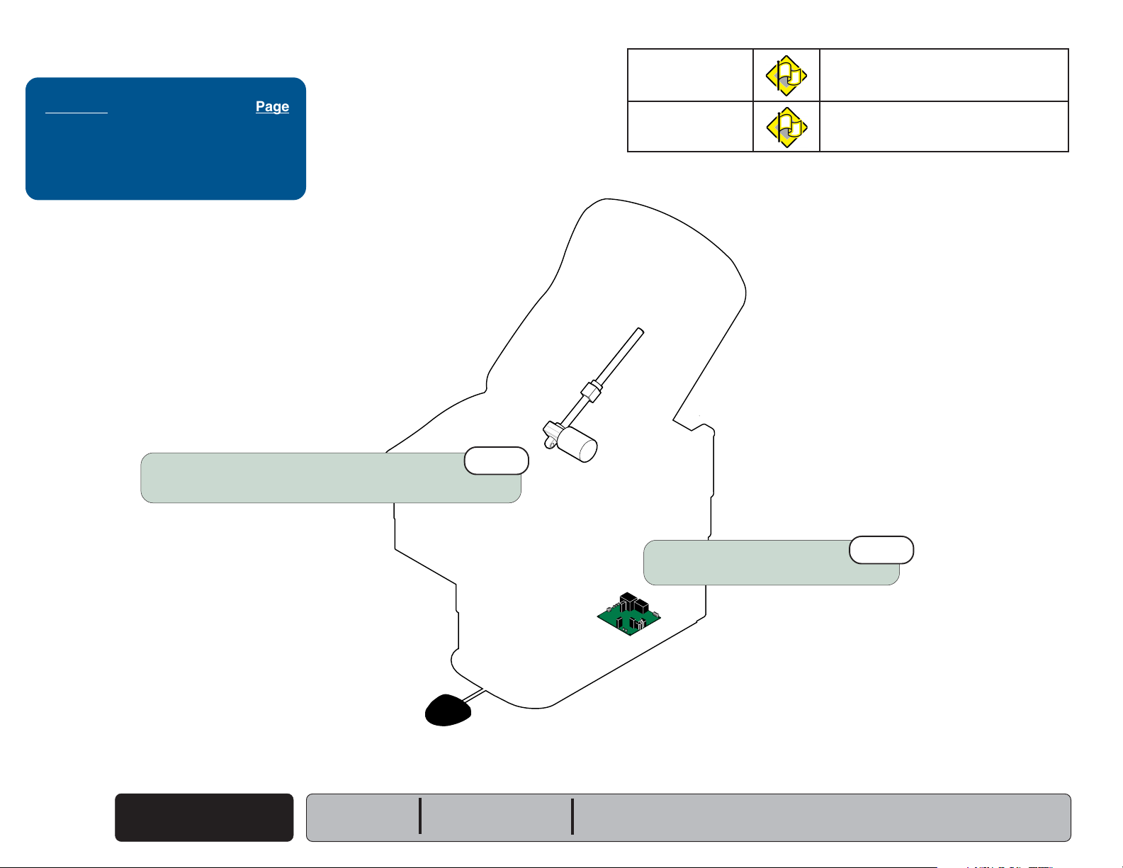
Drawer Heater System (optional)
Go To Table Of Contents
Go To Page:
This illustration shows only the components that affect the drawer heater system.
A detailed description of current flow during this function also appears below.
Drawer Heater Operation
115 VAC is supplied directly to the Drawer Heater
switch thru two fuses on the Distribution Board.
[Voltage bypasses the Main PC Board].
When the drawer heater switch is turned ON,
current flows to the heater plate. When the heater
plate is energized, it warms the contents of the
drawer.
NOTE:
Line voltage (230 VAC) is supplied thru
two fuses
a transformer that reduces the line
voltage to 115 VAC before it reaches
the Distribution Board.
230 VAC models only
(located by the IEC inlet)
to
115 VAC
Troubleshooting
Troubleshooting
[Drawer Heater System]
Problem Page
Drawer Heater Does Not Warm Up:
Switch Does Not Illuminate
Switch Illuminates...........................
Drawer Heater Works Properly:
Switch Does Not Illuminate.............
Distribution Board Fuses
[Drawer Heater only]
............ A-24
A-25
A-26
Models:
Serial Numbers:
Heater Plate
222
(-003 /-004 /-007 /-008 /-010 /-016)
All
(-003 /-004 /-007 /-008 /-010 /-016)
223
All
115 VAC
622
(-002 /-004 /-006-008)
All
115 VAC
Heater Switch
MA629000i
623
(-002 /-004 /-008 / -010)
All
Drawer Heater System
A-23
© Midmark Corporation 2003 SF-1838
Page 33

Troubleshooting
Go To Table Of Contents
Go To Page:
noitcnuFsutatSmelborP
Drawer Heater Does not heat up.
Refer To: Page
Fuses ........................................... B-2
Drawer Heater System ............... B-23
Wiring Diagrams .......................... D-1
Exploded Views / Part Numbers .. E-1
Loose Wire Connections
(between heater switch and power cord)
1st
Heater Switch Does
2nd
Distribution Board Fuses
Refer to: Section B - Fuses
not illuminate
Drawer Heater System
A-24
© Midmark Corporation 2003 SF-1838
3rd
Perform
Heater Switch Test
Refer to: Section B - Drawer Heater System
Drawer
Models:
Serial Numbers:
MA628800i
222
(-003 /-004 /-007 /-008 /-010 /-016)
All
(-003 /-004 /-007 /-008 /-010 /-016)
223
All
(-002 /-004 /-006-008)
622
All
(-002 /-004 /-008 / -010)
623
All
Page 34

noitcnuFsutatSmelborP
Go To Table Of Contents
Go To Page:
Drawer Heater Does not heat up.
Heater Switch OK
Loose Wire Connections
(between heater switch and heater plate)
(Illuminates)
1st
Troubleshooting
Refer To: Page
Fuses ........................................... B-2
Drawer Heater System ............... B-23
Wiring Diagrams .......................... D-1
Exploded Views / Part Numbers .. E-1
Models:
Serial Numbers:
(-003 /-004 /-007 /-008 /-010 /-016)
222
All
Perform
Heater Plate Test
Refer to: Section B - Drawer Heater System
223
(-003 /-004 /-007 /-008 /-010 /-016)
All
Drawer
MA628900i
622
(-002 /-004 /-006-008)
All
2nd
(-002 /-004 /-008 / -010)
623
All
Drawer Heater System
A-25
© Midmark Corporation 2003 SF-1838
Page 35

Troubleshooting
Go To Table Of Contents
Go To Page:
Refer To: Page
Drawer Heater System ............... B-23
Wiring Diagrams .......................... D-1
Exploded Views / Part Numbers .. E-1
noitcnuFsutatSmelborP
Drawer Heater OK
Heater Switch Does
not illuminate
Replace Drawer Heater Switch
Refer to: Section B - Drawer Heater System
Drawer Heater System
A-26
© Midmark Corporation 2003 SF-1838
2nd
Models:
Serial Numbers:
MA628800i
222
(-003 /-004 /-007 /-008 /-010 /-016)
All
(-003 /-004 /-007 /-008 /-010 /-016)
223
All
(-002 /-004 /-006-008)
622
All
(-002 /-004 /-008 / -010)
623
All
Page 36

Table Receptacle (optional)
Go To Table Of Contents
Go To Page:
This illustration shows only the components that affect the table receptacle.
A detailed description of current flow also appears below.
Table Receptacle
115 VAC is supplied directly to the table
receptacle thru the circuit breaker(s)*.
[Voltage bypasses the Main PC Board].
NOTE:
There is a connection point for the receptacle
wiring harness at the distribution board.
Current does not flow thru the distribution board fuses.
Models w/drawer heater only
Toggle style
(Tripped = no power)
Push-Button style
(Tripped = no power)
Troubleshooting
Troubleshooting
[Table Receptacle]
Problem Page
No Power At Receptacle ...................
A-28
Circuit Breakers (2)
222/223
(-015 & -016)
622/623
(-007 & -008)
5
A
M
P
5
A
M
P
(Reset = power)
(Reset = power)
Circuit Breaker (1)*
(*Canadian models do not have a circuit breaker)
222/223
(-002 /-004 /-006 /-008)
(-011 thru -014)
622/623
(-001 /-002 /-005 /-006)
MA603405i
Models:
Serial Numbers:
Models:
Serial Numbers:
(-002 /-004 /-006 /-008)
222
(-011 thru -016)
All
(-002 /-004 /-006 /-008)
223
(-011 thru -016)
All
622
(-001 /-002)
(-005 thru -008)
All
623
(-001 /-002)
(-005 thru -008)
All
Table Receptacle
© Midmark Corporation 2003 SF-1838
Rev. 4/06
A-27
Page 37

Troubleshooting
Go To Table Of Contents
Go To Page:
Refer To: Page
Wiring Diagrams .......................... D-1
Exploded Views / Part Numbers .. E-1
Is circuit breaker tripped?
[Lift seat section to access circuit breaker(s) - press to reset]
Toggle style
(Tripped = no power)
(Reset = power)
1st
noitcnuFsutatSmelborP
Table Receptacle No power.
All other functions OK
5
A
M
P
5
A
M
P
A-28
© Midmark Corporation 2003 SF-1838
Table Receptacle
Replace receptacle
Models:
Serial Numbers:
Models:
Serial Numbers:
(-002 /-004 /-006 /-008)
3rd
222
(-011 thru -016)
All
Loose wire connections
(between table receptacle and power cord)
MA630601i
223
(-002 /-004 /-006 /-008)
(-011 thru -016)
All
622
(-001 /-002)
(-005 thru -008)
All
2nd
623
(-001 /-002)
(-005 thru -008)
All
Page 38

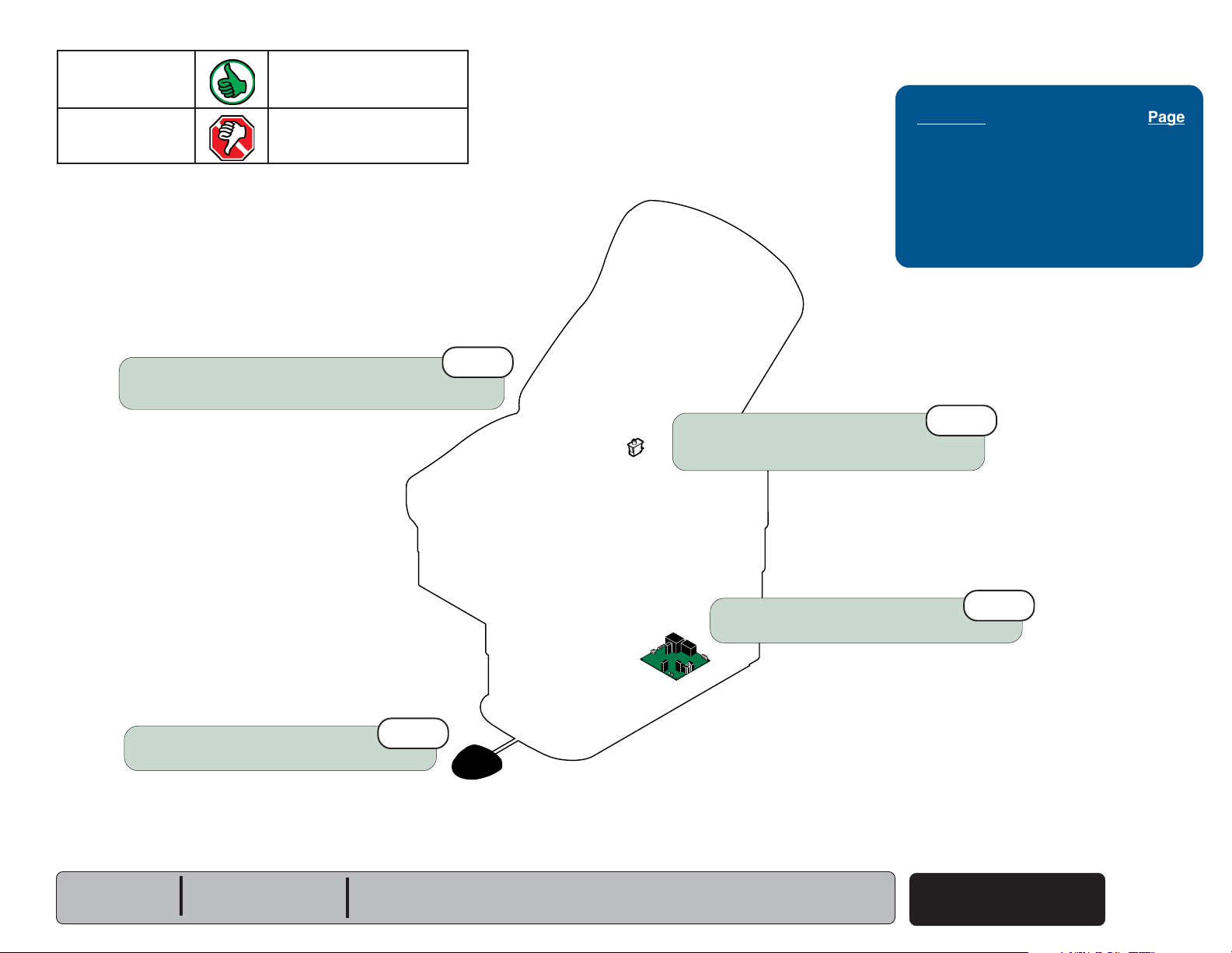
Auto Return Function
Go To Table Of Contents
Go To Page:
This illustration shows only the components that affect the Auto Return function.
Refer to the following page for a detailed description of current flow during this function.
Primary Fuses
[All Functions]
115 VAC
Base Motor Fuse
[Base Up & Down Functions]
48 VDC
Troubleshooting
Troubleshooting
[Auto Return Function]
Problem Page
Auto Return Function Does Not Work /
Base Down Function:
Malfunctioning ..................................
Works Properly...............................
A-2
A-31
Transformer Fuse
[All Functions]
Auto Return
Stop Switch
Models:
Serial Numbers:
Auto Return
Start Switch
623
14 VAC
(all)
All
Foot
Control
MA627800i
Auto Return
Limit Switches
[Auto Return function will not operate
if any of these limit switches are tripped]
Base Down
Limit Switch
Base Actuator
Auto Return
Function
© Midmark Corporation 2003 SF-1838
A-29
Page 39

Troubleshooting
Go To Table Of Contents
Auto Return Function
Power To Foot Control
115 VAC is supplied thru the two primary fuses
(F1 & F2)
[F4 fuse protects the transformer]
The transformer reduces the line voltage and
supplies 14 VAC to the foot control.
to the transformer on the PC board.
.
Auto Return Operation
NOTE
If either of the Auto Return limit switches or
the Base Down limit switch are tripped (open),
the Auto Return function will not operate.
When the Auto Return Switch is depressed
(closed), current
switch, to the PC Board.
(14 VAC)
flows thru the
NOTE
The Base Up / Down relay, located on the PC
Board, has four contacts (DPDT):
(2) Normally Open: Base Up function
(2) Normally Closed: Base Down function
Auto Return
A-30
© Midmark Corporation 2003 SF-1838
Function
When this voltage is applied, current
to the actuator motor thru the (2) Normally Closed
contacts of the Base Up / Down relay.
[The relay does not energize].
When voltage flows to the actuator thru the Normally
Closed contacts of the relay, the actuator motor runs
lowering the table.
Actuator Motor runs until:
1. Stop button is depressed.
2. Auto Return limit switch(es) is tripped.
3. 18 second software time limit is reached.
4. Base Down limit switch is tripped.
5. Fuse(s) opens (blows).
Models:
Serial Numbers:
(48 VDC)
[Primary, Base Motor, Transformer fuse]
623
(all)
All
flows
Page 40

noitcnuFsutatSmelborP
Go To Table Of Contents
Go To Page:
Auto Return No movement
Base Down OK
Loose Wire Connections
(esp. Foot Control, Auto Return Limit Switches)
1st
Troubleshooting
Refer To: Page
Limit Switches.............................. B-4
Foot Control ................................. B-6
Wiring Diagrams .......................... D-1
Exploded Views / Part Numbers .. E-1
Perform
Test Auto Return Start & Stop switches
Refer to: Section B - Foot Control
Models:
Serial Numbers:
Footswitch Test
623
(all)
All
3rd
MA630701i
Auto Return Limit Switches
Perform
Refer to: Section B - Limit Switches
Limit Switch Test.
© Midmark Corporation 2003 SF-1838
2nd
Auto Return
Function
A-31
Page 41

Troubleshooting
Go To Table Of Contents
Go To Page:
Upholstery Heater System (optional)
This illustration shows only the components that affect the Upholstery Heater System.
A detailed description of current flow during this function also appears below.
Upholstery Heater Operation
115 VAC is supplied thru the IEC inlet
to the Distribution PC board and then to
the Upholstery Heater PC board at J2 & J3.
Fuses F1 and F2 protect the circuit.
Circuitry on PC board converts 115 VAC to 12 VAC.
Troubleshooting
[Upholstery Heater System]
Problem Page
Heater Does Not Warm Up:
Switch Does Not Illuminate
Switch Illuminates ............................
Heater Works Properly:
Switch Does Not Illuminate ..............
............. A-33
A-34
A-35
Depressing and releasing the momentary
On/ Off Switch supplies approximately
12 VAC to the Upholstery Heater.
A timer on the PC board
On/ Off Switch is depressed)
activated for an 8 hour period unless the Switch
is depressed Off.
(Temperature knob not present on later models)
The upholstery heater temperature can be
regulated by the operator. Turning the
temperature knob will increase or decrease the
voltage to the heater. The temperature can be
varied to a maximum of 105O F (41O C).
A thermostat, located in Back Heating Pad,
opens at 131O F (55OC) +/- 10% removing
power from both Back and Seat heating
elements.
Upholstery Heater runs until:
1. Stop button is depressed.
2. 8 hour time limit is reached.
3. Fuse(s) on Upholstery Heater PCB
opens (blows).
(initiated when the
keeps the heater
Back
Upholstery
Heater
12 VAC
On/Off
Switch
Temperature
Control Knob
(Early models only)
Seat
12 VAC
Upholstery
Heater PCB
Upholstery
Heater
PCB
Fuses
F1
F2
Distribution
Board
115 VAC
Upholstery Heater
A-32
© Midmark Corporation 2003 SF-1838
Rev. 2/11
Models:
Serial Numbers:
(-002 /-004 /-006-008)
622
All
MA629600i
623
(-002 /-004 /-008 / -010)
All
Page 42

noitcnuFsutatSmelborP
Go To Table Of Contents
Go To Page:
Upholstery Heater Does not heat up.
Heater Switch Does
Loose Wire Connections
Distribution Board to Upholstery PCB,
Upholstery PCB to Heater Switch.
not illuminate
1st
Upholstery PCB Fuse(s)
Test Uph. PC Board fuses.
Refer to: Section B - Fuses
Troubleshooting
Refer To: Page
Fuses ........................................... B-2
Uph. Heater PC Board Test ........ B-29
Uph. Heater Switch Test ............. B-33
Wiring Diagrams .......................... D-1
Exploded Views / Part Numbers .. E-1
2nd
Perform
Refer to: Section B - Upholstery Heater System
Models:
Serial Numbers:
Uph. Heater Switch Test
(-002 /-004 /-006-008)
622
(-002 /-004 /-008 / -010)
All
3rd
623
All
Perform
Refer to: Section B - Upholstery Heater System
MA629900i
Uph. Heater PC Board Test
4th
Upholstery Heater
© Midmark Corporation 2003 SF-1838
A-33
Page 43

Troubleshooting
Go To Table Of Contents
Go To Page:
Refer To: Page
Fuses ........................................... B-2
Uph. Heater PC Board Test ........ B-29
Uph. Heater Test ........................ B-32
Uph. Heater Switch Test ............. B-33
Wiring Diagrams .......................... D-1
Exploded Views / Part Numbers .. E-1
3rd
Perform
Refer to: Section B - Upholstery Heater System
Uph. Heater Test
noitcnuFsutatSmelborP
Upholstery Heater Does not heat up.
Heater Switch Illuminates.
Perform
Refer to: Section B - Upholstery Heater System
Upholstery Heater
A-34
© Midmark Corporation 2003 SF-1838
Uph. Heater Switch Test
Perform
Refer to: Section B - Upholstery Heater System
Uph. Heater PC Board Test
Serial Numbers:
2nd
Models:
4th
622
(-002 /-004 /-006-008)
All
MA629900i
(-002 /-004 /-008 / -010)
623
All
Loose Wire Connections
Upholstery PCB to heater,
Back and Seat heater connection.
Upholstery PCB to heater switch.
1st
Page 44

noitcnuFsutatSmelborP
Go To Table Of Contents
Go To Page:
Upholstery Heater OK
Heater Switch Does not illuminate
Troubleshooting
Refer To: Page
Upholstery Heater Switch
Replacement .......................... B-25
Wiring Diagrams .......................... D-1
Exploded Views / Part Numbers .. E-1
Replace Uph. Heater Switch
Refer to: Section B - Upholstery Heater System
Models:
Serial Numbers:
622
(-002 /-004 /-006-008)
All
1st
(-002 /-004 /-008 / -010)
623
All
MA629900i
Upholstery Heater
A-35
© Midmark Corporation 2003 SF-1838
Page 45

Troubleshooting
Go To Table Of Contents
A-36
© Midmark Corporation 2003 SF-1838
Models:
Serial Numbers:
Page 46

Component Testing & Repair
Go To Table Of Contents
Click on the Go To Page button and enter the desired
page number. (Note: Letters are case sensitve. ex. B-2)
Go To Page:
Component
Testing & Repair
Components Page
Fuses ............................................... B-2
Limit Switches ...................................... B-4
Foot / Hand Control .............................. B-6
Base Actuator ....................................... B-11
Back Actuator
Back Release Mechanism
Main PC Board ..................................... B-19
Drawer Heater System ......................... B-23
Upholstery Heater System .................... B-29
(power) ..........................
(manual) .....
B-11
B-17
Section B
Models:
Serial Numbers:
© Midmark Corporation 2003 SF-1838
B-1
Page 47

Component Testing & Repair
Go To Table Of Contents
Go To Page:
Fuses
Location
Distribution Board
(Early models w/drawer heater)
Fuses Page
Location ............................................... B-2
Fuse Test ............................................. B-3
Access Procedures .............................. C-1
Wiring Diagrams ................................... D-1
Fuse Ratings & Part Numbers .............. E-24
Upholstery Heater PC Board
B-2
© Midmark Corporation 2003 SF-1838
Fuses
Distribution Board
(Later models w/drawer heater)
Models:
Serial Numbers:
Power Cord Inlet
(230V & Canadian models only)
Main PC Board
MA627400i
All
All
Page 48

Component Testing & Repair
Go To Table Of Contents
Fuses
Fuse Test
- continued
Fuse Test
Step 1: Set meter to 200
Ω.Ω.
Ω.
Ω.Ω.
Fuse Test
Step 2: Place meter probes
on each end of fuse.
Models:
Serial Numbers:
All
All
gndaeRreteMsutatSnoitcAderiuqeR
OL
Any
resistance Fuse is good.
reading
© Midmark Corporation 2003 SF-1838
Replace fuse.
Fuses
B-3
Page 49

Component Testing & Repair
Go To Table Of Contents
Go To Page:
Limit Switches
Location
Limit Switches Page
Location ............................................... B-4
Limit Switch Test .................................. B-5
Access Procedures .............................. C-1
Wiring Diagrams ................................... D-1
Part Number
(all) ....................
015-1055-00
Attention!
All limit switches are the same.
They can be "traded" to troubleshoot.
Base Down Limit Switch
Affected Functions: Base DOWN
Auto Return (623 only)
623 only
Auto Return Limit Switches (2)
Affected Function: Auto Return
Back Up Limit Switch
Affected Function: Back UP
MA627600i
Base Up Limit Switch
Affected Function: Base UP
Back Down Limit Switch
Affected Function: Back DOWN
223 / 623 only
223 / 623 only
B-4
© Midmark Corporation 2003 SF-1838
Limit Switches
Models:
Serial Numbers:
All
All
Page 50

Component Testing & Repair
Go To Table Of Contents
Limit Switches
- continued
Limit Switch Test
Attention!
All limit switches are the same.
They can be "traded" to troubleshoot.
Limit Switch Test
Step 1: Remove limit switch.
Disconnect wires.
MA627700i
Limit SwitchTest
Step 2: Set meter to 200
Limit Switch Test
Step 3: Place meter probes on
Note: Check switch 'tripped' and 'untripped'.
Ω.Ω.
Ω.
Ω.Ω.
COM and NC
terminals.
With switch 'tripped'...
Models:
Serial Numbers:
gndaeRreteMsutatSnoitcAderiuqeR
OL
less than or = to Replace switch
5 ohms
Switch is good.
Perform next check.
All
All
With switch 'untripped'...
gndaeRreteMsutatSnoitcAderiuqeR
OL
Any
resistance Switch is good.
reading Perform next check.
Replace switch
Limit Switches
© Midmark Corporation 2003 SF-1838
B-5
Page 51

Component Testing & Repair
Go To Table Of Contents
Go To Page:
Foot / Hand Control
Foot Switch Test - 222 / 622
Foot SwitchTest
Step 1: Remove foot control switch.
Note: Refer to Foot Switch Replacement 222 / 622.
Foot Switch Test
Step 2: Set meter to
Ω.Ω.
Ω.
Ω.Ω.
Foot Switch Test
Step 3: Place meter probes on
COM and NO
terminals.
Foot / Hand Control Page
Foot Switch Test
Foot / Hand Control Test
Foot Switch Replacement:
222 / 622 ...........................................
223 / 623 (old style foot control) ........
Switch Membrane Replacement:
223 / 623 (new style foot control).......
623 Hand Control ..............................
Wiring Diagrams ................................... D-1
Exploded View / Part Numbers:
Foot Contol - 222 / 622 ......................
Foot Control - 223 .............................
Foot Control - 623 .............................
Hand Control - 623 ............................
* multiple pages due to model / serial # break
- 222 / 622 .................
- 223 / 623 ....
B-6
B-7
B-8
B-9
B-10
B-10
E-26
E-27*
E-28*
E-29
With switch 'tripped'...
less than or = to Switch is good.
5 ohms Perform next check.
OL
Foot / Hand Control
B-6
© Midmark Corporation 2003 SF-1838
gndaeRreteMsutatSnoitcAderiuqeR
Replace switch
Models:
Serial Numbers:
222 (all)
All
Note: Check switch
'tripped' and 'untripped'.
With switch 'untripped'...
Any
reading
OL
622 (all)
gndaeRreteMsutatSnoitcAderiuqeR
resistance Replace switch.
Switch is good.
Perform next check.
All
Page 52

Component Testing & Repair
Go To Table Of Contents
Foot / Hand Control
Foot / Hand Control Test
- continued
- 223 / 623
Foot / Hand Control Test
Step 1: Disconect wire harness from J8* on main PC board
* Note: Model 623 only: If the foot or hand control to be tested
is plugged into the inlet at the head end of the table,
disconnect harness from J7 on main PC board.
J8
Foot / Hand Control Test
Step 2: Set meter to
Ω.Ω.
Ω.
Ω.Ω.
..
.
..
With switch 'untripped'...
gndaeRreteMsutatSnoitcAderiuqeR
Any
resistance Replace switch /
reading switch membrane.
Switch is good.
Perform next check.
(Base Down)
Red
(com.)
Black
OL
With switch 'tripped'...
gndaeRreteMsutatSnoitcAderiuqeR
Foot / Hand Control Test
Step 3: Place one meter probe on black wire
(common)
Place other meter probe on the wire that
corresponds to the switch to be tested:
Switch Wire Color
Base Up .......... white
Base Down ...... red
Back Up ........... green
Back Down ...... orange
Auto Return ..... blue
Stop ................. brown
Models:
Serial Numbers:
of foot / hand control harness.
223 (all)
All
623 (all)
All
Probe position to test:
Base Down switch
MA727300i
less than or = to Switch is good.
5 ohms Perform next check.
OL
Foot / Hand Control
© Midmark Corporation 2003 SF-1838
Replace switch /
switch membrane.
B-7
Page 53

Component Testing & Repair
Go To Table Of Contents
Foot / Hand Control
- continued
Foot Switch Replacement - 222 / 622
Removal
Step 1: Remove cover.
Installation
Step 2: Install cover
.
Removal
Step 2: Remove switch.
Disconnect wires.
Foot / Hand Control
B-8
© Midmark Corporation 2003 SF-1838
Models:
Serial Numbers:
222 (all)
All
MA628300i
622 (all)
All
Installation
Step 1: Install switch.
Connect wires.
Note: Be sure insulating
material is in place.
Page 54

Component Testing & Repair
Go To Table Of Contents
Foot / Hand Control
- continued
Foot Switch Replacement - 223 / 623*
* Old-style Foot Control
Installation
Step 3: Connect coil cord & pedal switch
wire harness to PC board.
Removal
Step 3: Disconnect coil cord & pedal
switch wire harness from PC board.
Installation
Step 2: Insert switch wires into connector
Connect wire harness to PC board.
Removal
Step 4: Disconnect proper wire harness from PC board.
Press tabs, then disconnect faulty switch wires.
Tab
.
Removal
Step 1: Disconnect coil cord from table.
Remove strain relief clamp.
Installation
Step 5: Install strain relief clamp.
Connect coil cord to table.
Models:
Serial Numbers:
Removal
Step 2: Remove four screws.
Installation
Step 4: Install top section.
223 (-001 thru -014)
SC1000 thru present SD1000 thru present
SE1000 thru present SF1000 thru present
V2200 thru V3302
Separate top section.
623 (-001 thru -006)
SL1000 thru present SM1000 thru present
V2200 thru V3302
Installation
Step 1: Install switch
Removal
Step 5: Remove faulty switch.
Foot / Hand Control
© Midmark Corporation 2003 SF-1838
.
B-9
Page 55

Component Testing & Repair
Go To Table Of Contents
Foot / Hand Control
- continued
Switch Membrane Replacement - 223 / 623*
* New-style Foot Control
Installation
Step 1: Install touch pad onto switch panel.
Removal
Step 3: Peel touch pad off of switch panel.
Installation
Step 2: Insert control cord thru hole in base.
Connect to membrane connector.
Note: Slide strain relief block (on cord) into slot on base.
Hand Control - 623 only
Removal
Step 1: Remove base plate.
Installation
Step 3: Install base plate.
Foot / Hand Control
B-10
© Midmark Corporation 2003 SF-1838
Removal
Step 2: Disconnect control cord
MA727600i
Models:
Serial Numbers:
from membrane connector.
223 (all)
V3303 thru present
623 (all)
V3303 thru present
Page 56

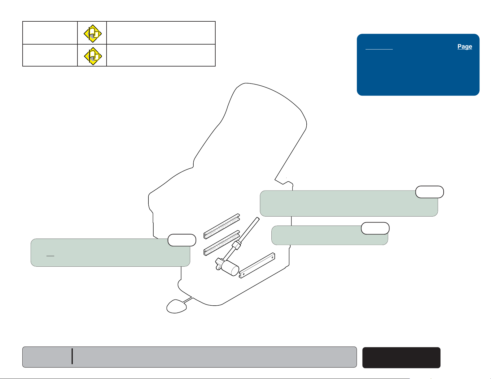
Base / Back Actuator
Go To Table Of Contents
Go To Page:
This illustration shows the three seviceable components of the actuator.
Use the table below to isolate the malfunctioning part.
melborPnoitcAderiuqeR
Motor runs, but makes grinding noise. Clean Ball Screw threads.
Replace Ball Screw Assy.
Motor runs, but table does not move. Inspect / replace
Motor Coupler.
-or
Component Testing & Repair
Base / Back Actuator Page
Actuator Motor Test ............................. B-12
Replacement:
Base Actuator ...................................
Back Actuator (223 / 623) ..................
Wiring Diagrams ................................... D-1
Exploded View / Part Numbers:
Back Actuator (223 / 623) ..................
Base Actuator....................................
B-13
B-15
E-12
E-21
Motor does not run. Perform
Actuator Motor Test
Actuator Motor
Ball Screw Assembly
MA628200i
Motor Coupler
Models:
Serial Numbers:
All
All
Base / Back Actuator
© Midmark Corporation 2003 SF-1838
B-11
Page 57

Component Testing & Repair
Go To Table Of Contents
Base / Back Actuator
Actuator Motor Test
Actuator Motor Test
Step 2: Set meter to 200
- continued
Caution
Unplug power cord before
removing PC Board cover.
Actuator Motor Test
Step 1: Disconnect actuator wires from PC Board.
[Base Actuator: J2 & J3]
[Back Actuator: J4 & J5
Note: Refer to next page to access PC Board.
(223 / 623 only)
]
Base / Back Actuator
B-12
© Midmark Corporation 2003 SF-1838
Rev. 7/10/12
Models:
Serial Numbers:
Actuator Motor Test
Step 3: Place meter probes on actuator wires.
gndaeRreteMsutatSnoitcAderiuqeR
2- 3
0
All
All
Motor is good.
Perform next check.
Replace motor.
Page 58

MA628000i
15 In
38.1 cm
Base Actuator
Go To Table Of Contents
Go To Page:
Replacement
Component Testing & Repair
Access Procedures Page
Table Shrouds
Removal / Installation ........................ C-2
Manually Raising / Lowering Table ....... C-5
Removal
(see Access Procedures)
Step 1: Remove table shrouds.
Installation
(see Access Procedures)
Step 7: Replace table shrouds.
Removal
Step 2: Position table so that bottom of
upperwrap is approx. 15 in. from floor.
Note: If necessary, manually raise / lower table.
(see Access Procedures)
Caution
Unplug power cord before
removing PC Board cover.
Removal
Step 3: Remove PC Board cover.
Installation
Step 6: Replace PC Board cover.
Removal
Step 4: Cut cable ties.
Installation
Step 4: Connect base actuator motor wires.
Note: Clamp must be installed over
stripped portion of actuator wire.
Removal
Step 5: Disconnect base
actuator motor wires.
Models:
Serial Numbers:
All
All
Installation
Step 5: Replace cable ties.
Base / Back Actuator
© Midmark Corporation 2003 SF-1838
Rev. 7/10/12
B-13
Page 59

Component Testing & Repair
MA628100i
Go To Table Of Contents
Base Actuator
Replacement
- continued
- continued
Caution
Use an assistant when laying / lifting table.
Remove all accessories (chair arms, storage pod, etc.)
Removal
Step 6: Lay table down on LH side.
Installation
Step 3: Carefully lift table upright.
Newer Models
Removal
Step 8: Remove two nuts / hex bolts.
Newer models:
Older models:
Remove actuator. Unscrew retaining plate.
Remove U-plate.
Unscrew actuator block from mounting block.
Installation (Newer Models)
Step 1: Thread retaining plate onto actuator block.
Retaining
Plate
Mounting Block
Insert actuator thru mounting block.
Secure retaining plate to mounting block.
Older Models
U-Plate
Base / Back Actuator
B-14
© Midmark Corporation 2003 SF-1838
Removal
Step 7: Remove clevis pin.
Pull base out to its full extension.
Pivot actuator toward head end.
Installation
Step 2: Pivot actuator toward foot end.
Push base together.
Install clevis pin & clip ring.
Models:
Serial Numbers:
Rev. 7/10/12
Actuator Block
Installation (Older Models)
Step 1: Thread actuator block 1/2 way down shaft.
Thread actuator block into mounting block.
Install U-plate.
All
All
Page 60

Back Actuator
Go To Table Of Contents
Go To Page:
Replacement
Component Testing & Repair
Access Procedures Page
Table Shrouds
Removal / Installation ........................ C-2
Removal
(see Access Procedures)
Step 1: Remove outer shrouds.
Note: The inner and middle shrouds will drop
down. It is not necessary to remove them.
Installation
Step 8: Replace shrouds.
Removal
Step 4: Cut all cable ties.
Installation
Step 6: Replace all cable ties.
Caution
Unplug power cord before
removing PC Board cover.
Removal
Step 2: Remove PC Board cover.
Installation
Step 7: Replace PC Board cover.
Removal
Step 3: Disconnect back
actuator motor wires.
Models:
Serial Numbers:
223 (all)
All
623 (all)
All
Installation
Step 5: Connect back
actuator motor wires.
Base / Back Actuator
© Midmark Corporation 2003 SF-1838
MA633000i
Rev. 7/10/12
B-15
Page 61

Component Testing & Repair
Go To Table Of Contents
Back Actuator
Replacement
- continued
- continued
Mounting bracket style may vary.
The procedure is similar.
Removal
Step 6: Remove top clevis pin.
Installation
Step 3: Install top clevis pin.
Removal
Step 8: Remove bottom clevis pin.
Remove actuator.
Installation
Step 1: Route motor wires.
Install bottom clevis pin.
Base / Back Actuator
B-16
© Midmark Corporation 2003 SF-1838
Installation
Step 4: Secure top cover with four screws.
Models:
Serial Numbers:
Removal
Step 5: Remove four screws
securing top cover.
223 (all)
All
623 (all)
All
Removal
Step 7: Remove top cover.
Installation
Step 2: Slide top cover over actuator.
MA633901i
Page 62

MA611901i
Back Release Mechanism
Go To Table Of Contents
Go To Page:
Back Release Handle Adjustment
Handle Adjustment
Step 1: Raise back section.
Note: If back section will not move, lift seat
section then remove clevis pin from bottom
of gas cylinder.
Component Testing & Repair
Handle Adjustment
Step 3: Rotate cam until cylinder releases.
Rotate cam back until cylinder locks in place.
Hold cam in place.
Back Release Mechanism Page
Back Release Handle Adjustment ........ B-17
Gas Cylinder
Replacement & Adjustment ............... B-18
Exploded View / Part Numbers ............. E-10*
* multiple pages due to model / serial # break
Handle Adjustment
Step 4: Pivot handles down until
they contact back section.
Note: Cam should not move.
Models:
Serial Numbers:
222 (all)
All
622 (all)
All
Handle Adjustment
Step 2: Loosen two set screws.
Handle Adjustment
Step 5: Tighten two set screws.
Back Release
Mechanism
© Midmark Corporation 2003 SF-1838
B-17
Page 63

Component Testing & Repair
Go To Table Of Contents
Back Release Mechanism
- continued
Gas Cylinder Replacement & Adjustment
Removal
Step 1: Lower back section all the way down.
Installation
Step 2: Hold cylinder shaft.
Extend shaft 2-3 in.
(Squeeze release handle gently)
Removal
Step 2: Remove clevis pin.
Note:
If clevis pin is inaccessible,
refer to:
Top Cover Removal
below.
Installation
Step 3: Install clevis pin.
Perform
Adjustment
Adjustment
Step 2: Tighten jam nut.
Adjustment
Step 1: Screw cylinder in/out one turn.
Check for proper operation.
Repeat as necessary.
Note: If cylinder drifts, screw OUT.
If cylinder does not release, screw IN.
.
Removal
Step 3: Loosen jam nut.
Unscrew cylinder.
Back Release
B-18
© Midmark Corporation 2003 SF-1838
Mechanism
Top Cover Removal
Step 1: Lower table shrouds.
Remove four screws.
Raise top cover to access clevis pin.
Models:
Serial Numbers:
(Refer to Section C)
222 (all)
All
Installation
Step 1: Screw cylinder in until
3-4 threads are exposed.
MA607602i
622 (all)
All
Page 64

Main PC Board
Go To Table Of Contents
Go To Page:
This illustration shows the location of the fuses on the Main PC Board.
Use the table below to determine the required action.
melborPnoitcAderiuqeR
Base actuator motor does not run. Check fuses
Perform
Back actuator motor does not run. Check fuses
Perform
(F1& F2, F3, F4)
Base Relay Test
(F1& F2, F3, F5)
Back Relay Test
.
.
Component Testing & Repair
Main PC Board Page
Base Relay Test ................................. B-20
Back Relay Test ................................. B-21
Replacement ...................................... B-22
Wiring Diagrams ................................. D-1
Part Numbers
222 / 622 ......................................... E-22*
223 / 623 ......................................... E-23
* multiple pages due to model / serial # break
Base Relay
• 222 / 622 ......... single function / one relay
Fuses:
F1 & F2 ........ Primary Fuses
F3 ................. Base Motor Fuse
F4 ................. Transformer Fuse
(affect all functions)
(affects Base Up / Down)
(affects all functions)
• 223 / 623 ......... dual function / two relays
Fuses:
F1 & F2 ........ Primary Fuses
F3 ................. Base Motor Fuse
F4 ................. Transformer Fuse
F5 ................. Back Motor Fuse
(affect all functions)
(affects Base Up / Down)
(affects all functions)
(affects Back Up / Down)
(Base Relay)
(Base Relay & Back Relay)
222 / 622
Base Relay
Back Relay
(223 & 623 only)
(223 & 623 only)
223 / 623
MA628600i
Models:
Serial Numbers:
All
All
Main PC Board
© Midmark Corporation 2003 SF-1838
B-19
Page 65

Component Testing & Repair
Go To Table Of Contents
Main PC Board
Base Relay Test
- continued
Base Relay Test
Step 1: Set meter to VDC.
Note: Wires must remain connected
to PC Board to perform this test.
Base Relay Test
Step 2: Clip meter test hooks on
terminals at J2 and J3.
Base Relay Test
Step 3: Activate Base Up / Down function
using the foot or hand control.
Main PC Board
B-20
© Midmark Corporation 2003 SF-1838
Rev. 4/11
Models:
Serial Numbers:
All
All
J3
J2
MA718400i
gndaeRreteMsutatSnoitcAderiuqeR
approx.
48 VDC
0 VDC
PC Board is good.
Perform next check.
Replace PC Board.
Page 66

Component Testing & Repair
Go To Table Of Contents
Main PC Board
Back Relay Test
- continued
Back Relay Test
Step 1: Set meter to VDC.
Note: Wires must remain connected
to PC Board to perform this test.
Base Relay Test
Step 2: Clip meter test hooks on
terminals at J4 and J5.
Back Relay Test
Step 3: Activate Back Up / Down function
using the foot or hand control.
Models:
Serial Numbers:
223 (all)
All
623 (all)
All
J5
J4
MA718500i
gndaeRreteMsutatSnoitcAderiuqeR
approx.
48 VDC
0 VDC
PC Board is good.
Perform next check.
Replace PC Board.
Main PC Board
© Midmark Corporation 2003 SF-1838
Rev. 4/11
B-21
Page 67

Component Testing & Repair
MA631500i
Go To Table Of Contents
Go To Page:
Main PC Board
- continued
Replacement
Removal
(see Access Procedures)
Step 1: Remove outer shrouds.
Note: The inner and middle shrouds will drop
down. It is not necessary to remove them.
Installation
(see Access Procedures)
Step 4: Replace outer shrouds.
Caution
Unplug power cord before
removing PC Board cover.
Removal
Step 2: Remove PC Board cover.
Installation
Step 3: Replace PC Board cover.
Access Procedures Page
Table Shrouds
Removal / Installation ........................ C-2
Manually Raising / Lowering Table ....... C-5
Note: 222 / 622 PC Board is shown.
223 / 623 will have additional wiring.
Removal
Step 3: Disconnect ground wire.
Installation
Step 2: Connect ground wire.
Connect all wiring.
Note: Boards manufactured after 6/05
B-22
will beep for approximately three
seconds when table is first pluged in.
Main PC Board
© Midmark Corporation 2003 SF-1838
Tag and disconnect wiring from PC Board.
Rev. 7/10/12
Models:
Serial Numbers:
All
All
Removal
Step 4: Remove PC Board.
Tip: Push latches back, then lift off
of mounting studs.
Installation
Step 1: Install PC Board.
Page 68

Drawer Heater System
Go To Table Of Contents
Go To Page:
Use the table below to determine the required action.
[This table applies to all models (222 / 223 / 622 / 623)]
melborPnoitcAderiuqeR
Drawer heater does not warm up. Perform
Heater switch does not illuminate
Drawer heater does not warm up. Perform
Heater switch illuminates.
Drawer heater - OK Replace heater switch.
Heater switch does not illuminate
Heater Switch Test - 222 / 223
Heater Switch Test
Step 2: Set meter to 200 VAC
Heater Switch Test
Heater Plate Test
Component Testing & Repair
Drawer Heater System Page
Distribution Board Fuses ...................... B-2
Heater Switch Test:
222 / 223 ...........................................
622 / 623 ...........................................
Switch Replacement 622 / 623 ............. B-25
Heater Plate Test:
222 / 223 ...........................................
622 / 623
Heater Plate Replacement.................... B-28
Wiring Diagrams ................................... D-1
Part Numbers ....................................... E-30*
* multiple pages due to model / serial # break
..
.
..
.......................................... B-27
B-23
B-24
B-26
Models:
Serial Numbers:
222
All
Heater Switch Test
Step 1: Remove heater switch.
Disconnect two incoming power wires.
Heater Switch Test
Step 3: Place meter probes on incoming power wires.
223
All
approx.
115 VAC
0 VAC
gndaeRreteMsutatSnoitcAderiuqeR
Replace switch.
Switch OK.
Check connections & fuses
Drawer Heater
System
© Midmark Corporation 2003 SF-1838
B-23
Page 69

Component Testing & Repair
Go To Table Of Contents
Go To Page:
Drawer Heater System
Heater Switch Test - 622 / 623
Caution
Unplug power cord before
removing stirrup guide.
Removal
Step 1: Remove stirrup guide.
Note: If necessary, remove chair arm
brace (see Access Procedures).
Installation
Step 2: Replace stirrup guide.
- continued
Access Procedures Page
Chair Arm Brace Removal .................... C-8
Heater Switch Test
Step 3: Set meter to 200 VAC
Heater Switch Test
Step 4: Place meter probes on two
white leads from switch.
Heater Switch Test
Step 5: Plug in power cord,
then depress switch to ON
Caution
Unplug power cord before
re-connecting electrical
leads.
B-24
© Midmark Corporation 2003 SF-1838
Drawer Heater
System
Rev. 7/10/12
Heater Switch Test
Step 2: Disconnect two white
leads from drawer heater
switch to the drawer heater.
Models:
Serial Numbers:
622
All
MA634800i
623
All
0 VAC
approx.
115 VAC
Installation
Step 1: Re-connect electrical
leads.
gndaeRreteMsutatSnoitcAderiuqeR
Replace switch.
Switch OK.
Check Heater Plate.
Page 70

Component Testing & Repair
Go To Table Of Contents
Go To Page:
Drawer Heater System
- continued
Heater Switch Replacement - 622 / 623
(This procedure also applies to the upholstery heater switch)
Removal
Step 1: Remove stirrup guide.
Note: If necessary, remove chair arm
brace (see Access Procedures).
Installation
Step 4: Replace stirrup guide.
Access Procedures Page
Chair Arm Brace Removal .................... C-8
Caution
Unplug power cord before
removing stirrup guide.
Removal
Step 2: Tag, then disconnect
wires from faulty
switch.
Installation
Step 3: Connect switch
electrical wires.
Removal
Step 3: Remove switch
housing.
Installation
Step 2: Install switch
housing.
Models:
Serial Numbers:
Removal
Step 4: Remove switch
assembly.
Installation
Step 1: Install switch
assembly.
622
All
623
All
MA636600i
MA636500i
Drawer Heater
System
© Midmark Corporation 2003 SF-1838
Rev. 7/10/12
B-25
Page 71

Component Testing & Repair
Go To Table Of Contents
Drawer Heater System
Heater Plate Test -222 / 223
- continued
Heater Plate Test
Step 2: Set meter to 2000
(2K)
Ω.Ω.
Ω.
Ω.Ω.
Heater Plate Test
Step 1: Remove heater switch.
Disconnect two heater plate wires (white).
Drawer Heater
B-26
© Midmark Corporation 2003 SF-1838
System
Models:
Serial Numbers:
222
All
Heater Plate Test
Step 3: Place meter probes on heater plate wires.
gndaeRreteMsutatSnoitcAderiuqeR
approx.
ΩΩ
360
Ω
ΩΩ
0
ΩΩ
Ω
ΩΩ
223
All
Heater plate is good.
Replace heater plate.
Page 72

Component Testing & Repair
Go To Table Of Contents
Go To Page:
Drawer Heater System
Heater Plate Test -622 / 623
Caution
Unplug power cord before
removing stirrup guide.
Removal
Step 1: Remove stirrup guide.
Note: If necessary, remove chair arm
brace (see Access Procedures).
Installation
Step 2: Replace stirrup guide.
- continued
Access Procedures Page
Chair Arm Brace Removal .................... C-8
Heater Plate Test
Step 3: Set meter to 2000
(2K)
Heater Plate Test
Step 4: Place meter probes on
terminals of heater plate
wires.
Models:
Serial Numbers:
622
All
Heater Plate Test
Step 2: Disconnect two white
leads from drawer
heater switch to the
drawer heater.
623
All
MA634900i
approx.
360
0
Installation
Step 1: Re-connect electrical
leads.
gndaeRreteMsutatSnoitcAderiuqeR
Heater plate is good.
Drawer Heater
System
© Midmark Corporation 2003 SF-1838
Perform next check.
Replace heater plate.
Rev. 7/10/12
B-27
Page 73

Component Testing & Repair
Go To Table Of Contents
Drawer Heater System
Heater Plate Replacement
- continued
Removal
Step 1: Remove screw(s) from drawer slides.
Installation
Step 3: Install screw.
Attention
If there is not a wire connection here, you must
lower table shrouds and remove the top cover in
order to disconnect / route heater plate wires.
Installation
Step 2: Route heater plate wires behind slide.
Connect wires.
Removal
Step 3: Disconnect heater plate wires.
Installation
Step 3: Install drawer.
Removal
Step 2: Push LH slide lever UP and RH lever DOWN.
Remove drawer.
Note: Slide levers are clear plastic.
Drawer Heater
B-28
© Midmark Corporation 2003 SF-1838
System
Serial Numbers:
Models:
Removal
Step 4: Remove heater plate.
Installation
Step 1: Install heater plate.
MA633800i
All
All
Page 74

MA636200i
Upholstery Heater System
Meter Reading Status Required Action
0 VAC
Check supply voltage to heater PC
board
s/n prior to V857486:
14-15 VAC
s/n V857487 to present:
7-8 VAC
Check upholstery heater.
Go To Table Of Contents
Go To Page:
Component Testing & Repair
Use the table below to determine the required action.
melborPnoitcAderiuqeR
Upholstery heater does not warm up. Perform
Heater switch does not illuminate
Upholstery heater does not warm up. Perform
Heater switch illuminates.
Upholstery heater - OK Replace heater switch.
Heater switch does not illuminate
Upholstery PC
Board Test
Upholstery Heater
Test
Upholstery Heater PC Board Test
(Output Voltage Test)
To Upholstery
Heater
Upholstery Heater System Page
Upholstery Heater PC Board Test:
Output Voltage Test ..........................
Supply Voltage Test ..........................
PC Board Replacement ........................ B-31
Upholstery Heater Test ......................... B-32
Upholstery Heater Switch Test ............. B-33
Wiring Diagrams ................................... D-1
Part Numbers ....................................... E-32
From Heater
PC Board
Output Voltage Test
Step 1: Disconnect leads to
upholstery heater.
B-29
B-30
Output Voltage Test
Step 2: Set meter to 20 VAC.
Output Voltage Test
Step 4: Press Upholstery (Green)
Heater switch ON.
Models:
Serial Numbers:
622
All
623
All
Output Voltage Test
Step 3: Place meter probes on leads
from upholstery heater PC
Board.
Upholstery Heater
System
© Midmark Corporation 2003 SF-1838
Rev. 5/10
B-29
Page 75

Component Testing & Repair
Go To Table Of Contents
Upholstery Heater System
- continued
Upholstery Heater PC Board Test - continued
(Supply Voltage Test)
Caution
Unplug power cord before
removing stirrup guide.
Supply Voltage Test
Step 1: Remove stirrup guide.
Note:
brace (see Access Procedures).
If necessary, remove chair arm
F2
F1
Upholstery
Heater PCB
J3
J2
J1
Supply Voltage Test
Step 2: Set meter to 200 VAC.
Upholstery Heater
B-30
© Midmark Corporation 2003 SF-1838
System
Rev. 7/10/12
Models:
Serial Numbers:
622
All
MA634901i
623
All
0
VAC
115
Supply Voltage Test
Step 3: Place meter probes on J2 &
J3 of Upholstery Heater PCB
and plug table into outlet.
gndaeRreteMsutatSnoitcAderiuqeR
VAC
Check incoming power
source to table.
Check connections &
F1 / F2 fuses on PCB.
Page 76

Component Testing & Repair
Go To Table Of Contents
Upholstery Heater System
Upholstery Heater PC Board Replacement
Caution
Unplug power cord before
removing PC Board cover.
Upholstery Heater PC Board Removal
Step 2: Depress release on standoffs and
remove PC Board.
Installation
Step 1: Replace PC Board.
- continued
Upholstery Heater PC Board Removal
Step 1: Tag, then disconnect leads to PC
board.
Installation
Step 2: Re-connect electrical leads.
Models:
Serial Numbers:
622
All
623
All
MA636800i
Upholstery Heater
System
© Midmark Corporation 2003 SF-1838
Rev. 7/10/12
B-31
Page 77

Component Testing & Repair
MA636300i
Go To Table Of Contents
Upholstery Heater System
Upholstery Heater Test
Upholstery Heater Test
Step 1: Disconnect leads to
- continued
To Upholstery
Heater
From Heater
PC Board
upholstery heater.
Upholstery Heater Test
Step 3: Place meter probes on leads
from upholstery heater.
Upholstery Heater Test
Step 2: Set meter to 200
Upholstery Heater
B-32
© Midmark Corporation 2003 SF-1838
System
ΩΩ
Ω.
ΩΩ
Serial Numbers:
Models:
622
All
623
All
0
3 - 4
gndaeRreteMsutatSnoitcAderiuqeR
ΩΩ
Ω
ΩΩ
ΩΩ
Ω
ΩΩ
Replace Upholstery
Check Upholstery
Heater Switch.
Page 78

Component Testing & Repair
Go To Table Of Contents
Upholstery Heater System
Upholstery Heater SwitchTest
- continued
Upholstery Heater SwitchTest
Step 3: Depress & hold in the Upholstery
Heater (Green) Switch
Note: For replacement procedures, refer to
Heater Switch Replacement in
Drawer Heater System
Upholstery Heater SwitchTest
Step 1: Set meter to 200
Ω.Ω.
Ω.
Ω.Ω.
Upholstery Heater SwitchTest
Step 2: Disconnect Black leads from Switch
and insert meter probes.
With switch 'tripped'...
gndaeRreteMsutatSnoitcAderiuqeR
Any
resistance Switch is good.
reading Perform next check.
OL
Models:
Serial Numbers:
Replace switch
622
All
623
All
MA634800i
With switch 'untripped'...
gndaeRreteMsutatSnoitcAderiuqeR
Any
resistance Replace switch.
reading
OL
Upholstery Heater
System
© Midmark Corporation 2003 SF-1838
Switch is good.
Perform next check.
B-33
Page 79

Component Testing & Repair
Go To Table Of Contents
Go To Page:
Click on the Go To Page button and enter the desired
page number. (Note: Letters are case sensitve. ex. C-2)
Access Procedures
Procedure Page
Table Shrouds
Manually Raising / Lowering Table ....... C-5
Upholstered Top
Ritter models .....................................
Midmark models ................................
Chair Arm / Brace Removal .................. C-8
Top Cover
Back Limit Switch Access ..................... C-9
(Remove / Install) .........
(Remove / Install)
(Remove Install) ..................
:
C-2
C-6*
C-7*
C-9
Section C
Models:
Serial Numbers:
© Midmark Corporation 2003 SF-1838
Rev. 3/06
C-1
Page 80

Component Testing & Repair
MA630800i
Go To Table Of Contents
Go To Page:
Table Shrouds
Removal / Installation
Note
Remove all accessories
(ex. chair arms)
before performing this procedure.
Removal
(Midmark models only)
Step 1: Remove magnetic cladding.
Refer To: Page
Exploded Views / Part Numbers:
Table Shrouds (Ritter models) ...........
Table Shrouds (Midmark models) .....
Removal
Step 2: Remove screw(s) from drawer slides.
Note: Tables w/o drawer heater do not have screws.
Installation
Step 7: Install screw(s) in drawer slides.
E-13*
E-14*
* multiple pages due to model / serial # break
C-2
© Midmark Corporation 2003 SF-1838
Table Shrouds
Rev. 6/07
MA776700i
Models:
Serial Numbers:
Installation
Step 6: Install drawer.
Removal
Step 3: Push LH slide lever UP and RH lever DOWN.
Remove drawer.
Note: Slide levers are clear plastic.
All
All
Page 81

Component Testing & Repair
Go To Table Of Contents
Table Shrouds
- continued
Removal / Installation
Removal
Step 4: Lower table to lowest height.
Disconnect table power cord.
Removal
Step 5: Lift seat section.
Remove two "inside" screws.
Note: If necessary, move receptacle cover
for better access to LH screw.
"Inside" Screw (LH)
Installation
Step 5: Install two "inside" screws.
Installation
Step 4: Install screws at head-end &
foot-end of outer shrouds.
Removal
Step 6: Remove screws from head-end
& foot-end of outer shrouds.
Note: Lower the drawer front to access
foot-end screws.
Models:
Serial Numbers:
"Inside" Screw (RH)
All
All
Removal
Step 7: Remove side screw & outer shroud.
Repeat for other side.
Installation
Step 3: Position outer shroud.
Install side screw.
Repeat on opposite side.
MA611602i
Table Shrouds
© Midmark Corporation 2003 SF-1838
Rev. 6/07
C-3
Page 82

Component Testing & Repair
MA612002i
Go To Table Of Contents
Table Shrouds
- continued
Removal / Installation
Installation
Step 1: Install six screws securing
bottom of inner shrouds.
Removal
Step 8: Remove six screws securing
bottom of inner shrouds.
Note: The shrouds on older 222 models do not have
C-4
the offset guides shown here. On these models,
align tabs
(not shown)
Table Shrouds
© Midmark Corporation 2003 SF-1838
so that they engage each other.
Rev. 11/09
Models:
Serial Numbers:
All
All
Installation
Step 2: Install two screws securing each set of shrouds.
Repeat at head end of table.
Removal
Step 9: Remove two screws securing each set of shrouds.
Repeat at head end of table.
Note: On older 222 models, there is a wire connecting the shrouds.
This must remain in place to ensure proper grounding.
Page 83

Manually Raising / Lowering Table
MA632200i
Go To Table Of Contents
Go To Page:
Step 1:Remove table shrouds.
(Access Procedures)
Component Testing & Repair
Refer To: Page
Exploded Views / Part Numbers:
Ritter Base Components ...................
Midmark Base Components ..............
Base Actuator....................................
* multiple pages due to model / serial # break
E-19*
E-20*
E-21
Models:
Serial Numbers:
All
All
Step 2: Run drill in reverse to raise table.
Run drill forward to lower table.
Note: Requires 5/16" socket w/ extension.
Manually
Raising / Lowering
© Midmark Corporation 2003 SF-1838
C-5
Page 84

Component Testing & Repair
MA632300i
Go To Table Of Contents
Go To Page:
Upholstered Top
(Ritter models)
Removal / Installation
(Soft Touch Top shown)
Attention
Seamless / Styled tops are one piece.
The replacment procedure is similar.
Installation
Step 2: Secure back section to hinge.
Removal
Step 2: Remove screws securing
back section to hinge.
Caution
Hold back section in place
when performing steps 1 & 2.
Refer To: Page
Exploded Views / Part Numbers:
Upholstery - Ritter :
Soft Touch ..................................
Seamless ....................................
Installation
Step 3: Secure back release bracket.
Removal
Step 1: Remove screws securing back
release bracket.
Note: The manual back model is shown.
The procedure for power back models
is similar.
E-6
E-7
C-6
© Midmark Corporation 2003 SF-1838
Upholstered Top
(Ritter models)
Rev. 7/11/12
Models:
Serial Numbers:
222 (-001 thru -014)
All
Removal
Step 3: Remove seat section.
Installation
Step 1: Secure seat section.
223 (-001 thru -014)
All
Page 85

Component Testing & Repair
Go To Table Of Contents
Go To Page:
Upholstered Top
(Ritter models)
Removal / Installation
(Soft Touch Top shown)
Installation
Step 1: Position upholstered top
& footrest pad on table.
Note: Be sure locking knobs align with
holes in back / seat mounting plates.
Refer To: Page
Exploded Views / Part Numbers:
Upholstery - Ritter :
Soft Touch ..................................
Seamless ....................................
Removal
Step 2: Remove upholstered top & footrest pad.
E-6.1
E-7.1
Models:
Serial Numbers:
222 (-015 thru -017)
All
223 (-015 thru -016)
All
Locking Knob
Unlocked
Removal
Step 1: Rotate all locking knobs to unlocked position.
Note: There are four locking knobs under back
section, and two knobs under seat section.
Locked
Installation
Step 2: Rotate locking knobs
to locked position.
MA727700i
Upholstered Top
(Ritter models)
© Midmark Corporation 2003 SF-1838
C-6.1
Page 86

Component Testing & Repair
Go To Table Of Contents
Go To Page:
Upholstered Top
(Midmark models)
Removal / Installation
Removal
Step 3: Lift back section to disengage velcro,
then push toward head end.
Installation
Step 1: Slide back section toward
foot end to engage T-block.
Refer To: Page
Exploded Views / Part Numbers:
Upholstery - Midmark:
Premium .....................................
Ultra-Premium .............................
E-8
E-9
Removal
Step 2: Hold mounting frame in place,
then lift seat section.
Note: Upholstery is secured with velcro.
Installation
Step 2: Lower seat section and press
down firmly to engage velcro.
Models w/ upholstery heater only
Removal
Step 1: Disconnect wire harness.
Installation
Step 3: Connect wire harness.
Note: Do not pinch wire.
C-7
© Midmark Corporation 2003 SF-1838
Upholstered Top
(Midmark models)
Models:
Serial Numbers:
622 (-001 thru -006)
All
MA634100i
623 (-001 thru -006)
All
Page 87

Component Testing & Repair
Go To Table Of Contents
Go To Page:
Upholstered Top
Removal / Installation
(Midmark models)
Step 2 applies only to models with optional upholstery heater.
Removal
Step 2: Disconnect upholstery heater harness.
Installation
Equipment Alert
Be sure harness is not pinched
between upholstery & upperwrap.
Step 2: Connect upholstery heater harness.
Installation
Step 1: Position upholstered top & footrest pad on table.
Note: Back support plate must slide under paper roll holder.
Refer To: Page
Exploded Views / Part Numbers:
Upholstery - Midmark:
Premium .....................................
Ultra-Premium .............................
Removal
Step 3: Remove upholstered top & footrest pad.
Note: Slide upholstery up to remove from back support plate.
Be sure locking knobs align with holes in back / seat
mounting plates.
E-8.1
E-9.1
Models:
Serial Numbers:
622 (-007 & -008)
All
Unlocked
623 (-007 thru -010)
All
Locking Knob
Installation
Step 3: Rotate locking knobs to locked position.
Removal
Locked
MA727800i
Step 1: Rotate all locking knobs to unlocked position.
Note: There are four locking knobs under back
section, and two knobs under seat section.
Upholstered Top
(Midmark models)
© Midmark Corporation 2003 SF-1838
Rev. 7/11/12
C-7.1
Page 88

Component Testing & Repair
MA612601i
Go To Table Of Contents
Chair Arms / Brace (optional)
Removal
Arm Removal
Step 1: Squeeze lever.
Remove chair arm.
Refer To: Page
Exploded Views / Part Numbers:
Refer to Midmark Medical Accessory
Service & Parts Manual (004-0096-00)
It may be necessary to remove the chair arm brace
when performing certain procedures.
Arm Brace Removal
Step 1: Remove table shrouds.
Arm Brace Removal
Step 3: Remove brace.
Chair Arms
C-8
© Midmark Corporation 2003 SF-1838
Lever
Models:
Serial Numbers:
Arm Brace Removal
Step 2: Remove two screws.
Repeat on opposite side.
All
This is an optional accessory
MA612702i
Page 89

Top Cover (Back Limit Switch Access)
Go To Table Of Contents
Go To Page:
Removal / Installation
Component Testing & Repair
Refer To: Page
Table Shrouds ...................................... C-2
Removal
Step 1: Lower table shrouds.
Refer to: Section C - Table Shrouds
Installation
Step 2: Reattach table shrouds.
Removal
Step 2: Remove screws
securing top cover.
223 / 623
Models
only
Back Up
Limit Switch
Back Down
Limit Switch
Removal
Note
The back limit switches can be accessed without completely
removing the top cover. But if removing the cover is necessary,
perform Step 3.
Step 3: Partially serparate the back lift cylinder as shown.
Slide top cover off of cylinder.
Installation
Step 2: Secure top cover with
screws removed in Step 2.
223 / 623
(Power Back Cylinder)
Installation
Step 1: Slide top cover over back cylinder.
Reattach back cylinder.
222 / 622
(Manual Back Cylinder)
Models:
Serial Numbers:
All
All
MA736300i
Top Cover
© Midmark Corporation 2003 SF-1838
C-9
Page 90

Wiring Diagrams
Go To Table Of Contents
Go To Page:
Click on the Go To Page button and enter the desired
page number. (Note: Letters are case sensitve. ex. D-2)
Model Page
Wiring Diagrams
222:
(-001 & -005) ....................................................
(-002 & -006) ....................................................
(-003 & -007) ....................................................
(-004 & -008) ....................................................
(-009 & -017) ....................................................
(-010) ................................................................
(-011 & -013)
(-012 & -014) ....................................................
(-015) ................................................................
(-016) ................................................................
.................................................... D-8
D-2
D-3
D-4
D-5
D-6
D-7
D-9
D-10
D-11
223:
(-001 & -005) ....................................................
(-002 & -006) ....................................................
(-003 & -007) ....................................................
(-004 & -008) ....................................................
(-009) ................................................................
(-010) ................................................................
(-011 & -013)
(-012 & -014) ....................................................
(-015) ................................................................
(-016) ................................................................
.................................................... D-18
D-12
D-13
D-14
D-15
D-16
D-17
D-19
D-20
D-21
622:
(-001) ................................................................
(-002) ................................................................
(-003)
.............................................................. D-6
(-004)
.............................................................. D-23
(-005)
.............................................................. D-8
(-006)
.............................................................. D-24
(-007)
.............................................................. D-10
(-008)
.............................................................. D-25
D-3
D-22
623:
(-001) ................................................................
(-002) ................................................................
(-003 & -009) ....................................................
(-004) ................................................................
(-005) ................................................................
(-006) ................................................................
(-007) ................................................................
(-008) ................................................................
(-010) ................................................................
D-26
D-27
D-28
D-29
D-30
D-31
D-32
D-33
D-29*
Section D
Models:
Serial Numbers:
Wiring Diagrams
© Midmark Corporation 2003 SF-1838
Rev. 3/06
D-1
Page 91

Wiring Diagrams
Go To Table Of Contents
Go To Page:
Refer To: Page
Fuses ............................................... E-24
IEC
Inlet
Blue
eriW
ssenraH:morF:oTrebmuNtraP
A
B
telnICEICPniaM
nwoD/pUesaB
sehctiwStimiL
A
1 3
J1
F3
Blk
C
Foot
Control
Up Limit
Switch
COM
NC
Wht
Wht
Down
B
Blk
Red
Wht
Wht
Grn/Yel
Wht
Blk
Blk
F4
3
4
J4
J5
J6
1
2
Brn
J7
J8
F1
F2
Main PC
Board
J3 J2
Wht
Limit
Switch
00-9751-510
draoB
CPniaM
draoB
)BmetIsedulcni(
00-9751-510
)AmetIsedulcni(
COM
NC
Blk
Blk
Choke
Wht
Wht
Blk
C
D-2
© Midmark Corporation 2003 SF-1838
rotautcAesaB
seriW
Wiring Diagrams
CPniaM
draoB
00-5361-510
)ekohcsedulcni(
Models:
Serial Numbers:
222
(-001 & -005)
all
Base Actuator
Blk
Page 92

Grn/Yel
Go To Table Of Contents
Go To Page:
Blue
Brn
Brn
Grn/Yel
Blue
Wiring Diagrams
Refer To: Page
D
IEC
Inlet
Brn
Blue
Grn/Yel
Grn/Yel
Blue
Brn
A
Fuses ............................................... E-24
Circuit
Breaker
Brn
E
Grn/Yel
Receptacle
Foot
Control
Blue
Up Limit
Switch
COM
NC
Down
Limit
Switch
COM
NC
Wht
Wht
Blk
Blk
Blk
Wht
Red
B
Wht
Wht
Blk
Blk
Base Actuator
F4
3
4
J4
J5
J6
1
2
J7
J8
F1
F2
Main PC
Board
J3 J2
Wht
Choke
Wht
Wht
Blk
1 3
J1
F3
Blk
Blk
C
eriW
ssenraH:morF:oTrebmuNtraP
A
B
C
D
E
telnICEICPniaM
nwoD/pUesaB
sehctiwStimiL
rotautcAesaB
seriW
rekaerBtiucriCtelnICEI
elcatpeceRtiucriC
00-9751-510
draoB
CPniaM
draoB
CPniaM
draoB
rekaerB
)BmetIsedulcni(
00-9751-510
)AmetIsedulcni(
00-5361-510
)ekohcsedulcni(
03-4951-510
00-5951-510
Models:
Serial Numbers:
222
(-002 & -006)
all
622
(-001)
all
Wiring Diagrams
© Midmark Corporation 2003 SF-1838
Rev. 3/06
D-3
Page 93

Wiring Diagrams
Go To Table Of Contents
Go To Page:
Refer To: Page
Fuses ............................................... E-24
Blue
D
IEC
Inlet
Brn
eriW
ssenraH:morF:oTrebmuNtraP
A
B
telnICEICPniaM
nwoD/pUesaB
sehctiwStimiL
C
rotautcAesaB
seriW
Wht
Wht
Blue
Grn/Yel
B
Blk
Red
Wht
Wht
Grn/Yel
Wht
Blk
Blk
Distribution
Board
Wht
Wht
F1
Grn/Yel
Brn
J1J2J3
J5J6J7
Brn
F2
Blue
J4
Foot
Control
J8
Up Limit
Switch
COM
NC
E
Down
Limit
Switch
Brn
00-9751-510
draoB
CPniaM
draoB
CPniaM
draoB
)BmetIsedulcni(
00-9751-510
Drawer
)AmetIsedulcni(
Heater
00-5361-510
)ekohcsedulcni(
Wht
Blue
Wht
Drawer
Heater
Switch
COM
NC
Blk
Blk
Base Actuator
F4
3
4
J4
J5
J6
1
2
Blue
Brn
J7
J8
F1
F2
Main PC
Board
J3 J2
Wht
Choke
Wht
Wht
Blk
A
1 3
J1
F3
Blk
C
Blk
D
E
D-4
© Midmark Corporation 2003 SF-1838
noitubirtsiD
draoB
telnICEI
/etalPretaeH
hctiwSretaeH
draoB
Wiring Diagrams
00-4951-510
noitubirtsiD
00-9261-510
Models:
Serial Numbers:
222
(-003 & -007)
all
Page 94

Blue
Go To Table Of Contents
Go To Page:
Grn/Yel
Wiring Diagrams
Refer To: Page
Fuses ............................................... E-24
E
IEC
Inlet
Brn
Distribution
Board
Wht
Wht
Drawer
Heater
F1
Grn/Yel
Brn
J1J2J3
J5J6J7
Brn
Wht
Wht
F2
Blue
2
5
Brn
J4
J8
Breaker
F
Brn
1
4
Drawer
Heater
Switch
G
Circuit
Blue
Blue
Brn
D
Grn/Yel
Brn
Receptacle
Foot
Control
Blue
Up Limit
Switch
COM
NC
Down
Limit
Switch
COM
NC
Wht
Wht
Blk
Blk
Blue
Blk
Red
Wht
Wht
Grn/Yel
Wht
Grn/Yel
B
Base Actuator
Blk
Blk
F4
3
4
J4
J5
J6
1
2
Blue
Brn
J7
J8
F1
F2
Main PC
Board
J3 J2
Wht
Choke
Wht
Wht
Blk
1 3
J1
F3
Blk
Blk
A
eriW
ssenraH
A
C
B
C
D
E
:morF:oTrebmuNtraP
telnICEICPniaM
draoB
nwoD/pUesaB
sehctiwStimiL
rotautcAesaB
seriW
CPniaM
draoB
CPniaM
draoB
elcatpeceRtiucriC
rekaerB
noitubirtsiD
draoB
telnICEI
00-9751-510
)BmetIsedulcni(
00-9751-510
)AmetIsedulcni(
00-5361-510
)ekohcsedulcni(
00-5951-510
00-4951-510
Models:
Serial Numbers:
222
(-004 & -008)
all
F
G
/etalPretaeH
hctiwSretaeH
rekaerBtiucriC
noitubirtsiD
draoB
noitubirtsiD
draoB
00-9261-510
03-8070-510
Wiring Diagrams
© Midmark Corporation 2003 SF-1838
Rev. 12/10
D-5
Page 95

Wiring Diagrams
Go To Table Of Contents
Go To Page:
Refer To: Page
Fuses ............................................... E-24
eriW
ssenraH:morF:oTrebmuNtraP
A
B
C
/telnICEI
/sredloHesuF
remrofsnarT
nwoD/pUesaB
sehctiwStimiL
rotautcAesaB
seriW
CPniaM
draoB
CPniaM
draoB
CPniaM
draoB
Fuse
Holder
Brn Blue
Brn Brn
IEC
Inlet
Fuse
Holder
Blue
A
Transformer
Grn/Yel
Brn
F4
Foot
Blk
Wht
Control
Red
B
Wht
Blk
Up Limit
Switch
COM
NC
00-0851-510
)BmetIsedulcni(
Down
Limit
Wht
Wht
Wht
Blk
J4
J5
J6
1
3
2
4
J7
J8
F1
F2
Main PC
Board
J3 J2
Wht
Switch
00-0851-510
)AmetIsedulcni(
00-5361-510
)ekohcsedulcni(
COM
NC
Blk
Blk
Base Actuator
Wht
Blk
Wht
Blue
1 3
J1
F3
Blk
C
Choke
Blk
D-6
© Midmark Corporation 2003 SF-1838
Wiring Diagrams
Rev. 9/10
Models:
Serial Numbers:
222
(-009 & -017)
all
622
(-003)
all
Page 96

Fuse
Go To Table Of Contents
Go To Page:
Holder
IEC
Inlet
Fuse
Holder
Wiring Diagrams
Refer To: Page
Fuses ............................................... E-24
Distribution
Board
Wht
Wht
Drawer
Heater
F1
Grn/Yel
Brn
J1J2J3
J5J6J7
Brn
Wht
Wht
Blue
F2
Blue
J4
J8
E
Brn
1
2
4
5
Blue
Drawer
Heater
Switch
Foot
Control
D
Up Limit
Switch
COM
NC
Down
Limit
Switch
COM
NC
Wht
Wht
Blk
Blk
Brn Blue
Brn Brn
Grn/Yel
Grn/Yel
F4
Blk
Wht
Red
B
Wht
Wht
Blk
Blk
J4
J5
J6
1
3
2
4
Base Actuator
A
J7
Brn
Blue
Brn
J8
F1
F2
Main PC
Board
J3 J2
Wht
Wht
Wht
Blk
Blue
1 3
J1
F3
Choke
Blk
Transformer
Blue
Blk
C
eriW
ssenraH:morF:oTrebmuNtraP
A
B
C
D
/telnICEI
/sredloHesuF
remrofsnarT
nwoD/pUesaB
sehctiwStimiL
rotautcAesaB
seriW
noitubirtsiD
draoB
CPniaM
draoB
CPniaM
draoB
CPniaM
draoB
remrofsnarT
00-0851-510
)BmetIsedulcni(
00-0851-510
)AmetIsedulcni(
00-5361-510
)ekohcsedulcni(
00-4951-510
Models:
Serial Numbers:
222
(-010)
all
E
/etalPretaeH
hctiwSretaeH
noitubirtsiD
draoB
00-9261-510
Wiring Diagrams
© Midmark Corporation 2003 SF-1838
Rev. 12/10
D-7
Page 97

Wiring Diagrams
Go To Table Of Contents
Go To Page:
Refer To: Page
Fuses ............................................... E-24
eriW
ssenraH:morF:oTrebmuNtraP
A
B
C
D
E
D-8
© Midmark Corporation 2003 SF-1838
telnICEICPniaM
draoB
nwoD/pUesaB
sehctiwStimiL
rotautcAesaB
seriW
noitalosI
remrofsnarT
elcatpeceR
CPniaM
draoB
CPniaM
draoB
EmetI
DmetI
Wiring Diagrams
00-2581-510
)BmetIsedulcni(
00-2581-510
)AmetIsedulcni(
00-5361-510
)ekohcsedulcni(
00-5481-510
00-5951-510
Models:
Serial Numbers:
222
(-011 & -013)
all
622
(-005)
all
Page 98

Wiring Diagrams
Go To Table Of Contents
Go To Page:
Refer To: Page
Fuses ............................................... E-24
eriW
ssenraH:morF:oTrebmuNtraP
Models:
Serial Numbers:
2
5
1
4
222
(-012 & -014)
all
A
B
C
D
E
F
G
telnICEICPniaM
nwoD/pUesaB
sehctiwStimiL
rotautcAesaB
seriW
noitalosI
remrofsnarT
elcatpeceRDmetI
/etalPretaeH
hctiwSretaeH
noitubirtsiD
draoB
00-2581-510
draoB
CPniaM
draoB
CPniaM
draoB
EmetI
noitubirtsiD
draoB
AmetI
)BmetIsedulcni(
00-2581-510
)AmetIsedulcni(
00-5361-510
)ekohcsedulcni(
00-5481-510
00-5951-510
00-9261-510
00-4951-510
Wiring Diagrams
© Midmark Corporation 2003 SF-1838
Rev. 12/10
D-9
Page 99

Wiring Diagrams
Go To Table Of Contents
Go To Page:
Refer To: Page
Fuses ............................................... E-24
Grn/Yel
Circuit
Breaker
Wire
Harness From: To: Part Number
A
B
BaseUp / Down
Limit Switches
Base Actuator
Wires
Main PC Board
Main PC Board
015-2003-00
015-1635-00
(includes choke)
C
Brn
Brn
Blue
Grn/Yel
D
Blue
Circuit
Breaker
Foot
Control
Up Limit
Switch
COM
NC
Down
Limit
Switch
COM
NC
Wht
Wht
Blk
Blk
Grn/Yel
F4
Blk
Wht
Red
A
Wht
Wht
Blk
Blk
J4
J5
J6
1
3
2
4
Main PC
J7
J8
F1
F2
Board
Brn
Blue
1 3
J1
F3
J3 J2
Wht
Blk
B
Choke
Wht
Blk
Wht
C
D
D-10
Circuit Breaker
(brown wire)
Circuit Breaker
(blue wire)
© Midmark Corporation 2003 SF-1838
Table Receptacle
Table Receptacle
Wiring Diagrams
Rev. 11/11
015-1886-00
015-1886-01
Models:
Serial Numbers:
222
(-015)
all
622
(-007)
all
Base Actuator
Blk
MA710600i
Page 100

Brn
Go To Table Of Contents
Go To Page:
C
Grn/Yel
Blue
D
F
Grn/Yel
Blue
Brn
J3
J10
J7
J4
J8
J9
J6
F1
J1
J2
F2
J5
Distribution Board
Blue
Brn
Wht
Wht
Drawer
Heater
Wht
Wht
Drawer
Heater
E
1
2
4
5
Switch
Brn
Brn
Blue
Foot
Control
Up Limit
Switch
COM
NC
Down
Limit
Switch
COM
NC
Blue
Wht
Wht
Blk
Blk
Blk
Wht
Red
A
Wht
Blk
Blk
Wht
Base Actuator
F4
J4
J5
J6
3
4
J7
1
2
Grn/Yel
Grn/Yel
J8
J9 J10
Main PC
Board
Wht
Choke
Wht
Wht
Blk
Grn/Yel
Brn
1
F1
F2
J3 J2
MA711000-01i
Blk
Brn
J1
Blk
Wiring Diagrams
Refer To: Page
Fuses ............................................... E-24
Blue
Blue
3
F3
Wire
Harness From: To:
E
F
BaseUp / Down
Limit Switches
Base Actuator
Wires
Circuit Breaker
(brown wire)
Circuit Breaker
(blue wire)
Heater Switch Distribution Board
Distribution
Board
Main PC Board 015-2003-00
Main PC Board
Table Receptacle
Table Receptacle
Main PC Board
B
A
B
C
D
Part
Number
015-1635-00
(incl. choke)
015-1886-00
015-1886-01
015-2004-00
015-2005-00
Models:
Serial Numbers:
222
(-016)
all
Wiring Diagrams
© Midmark Corporation 2003 SF-1838
Rev. 11/11
D-11
 Loading...